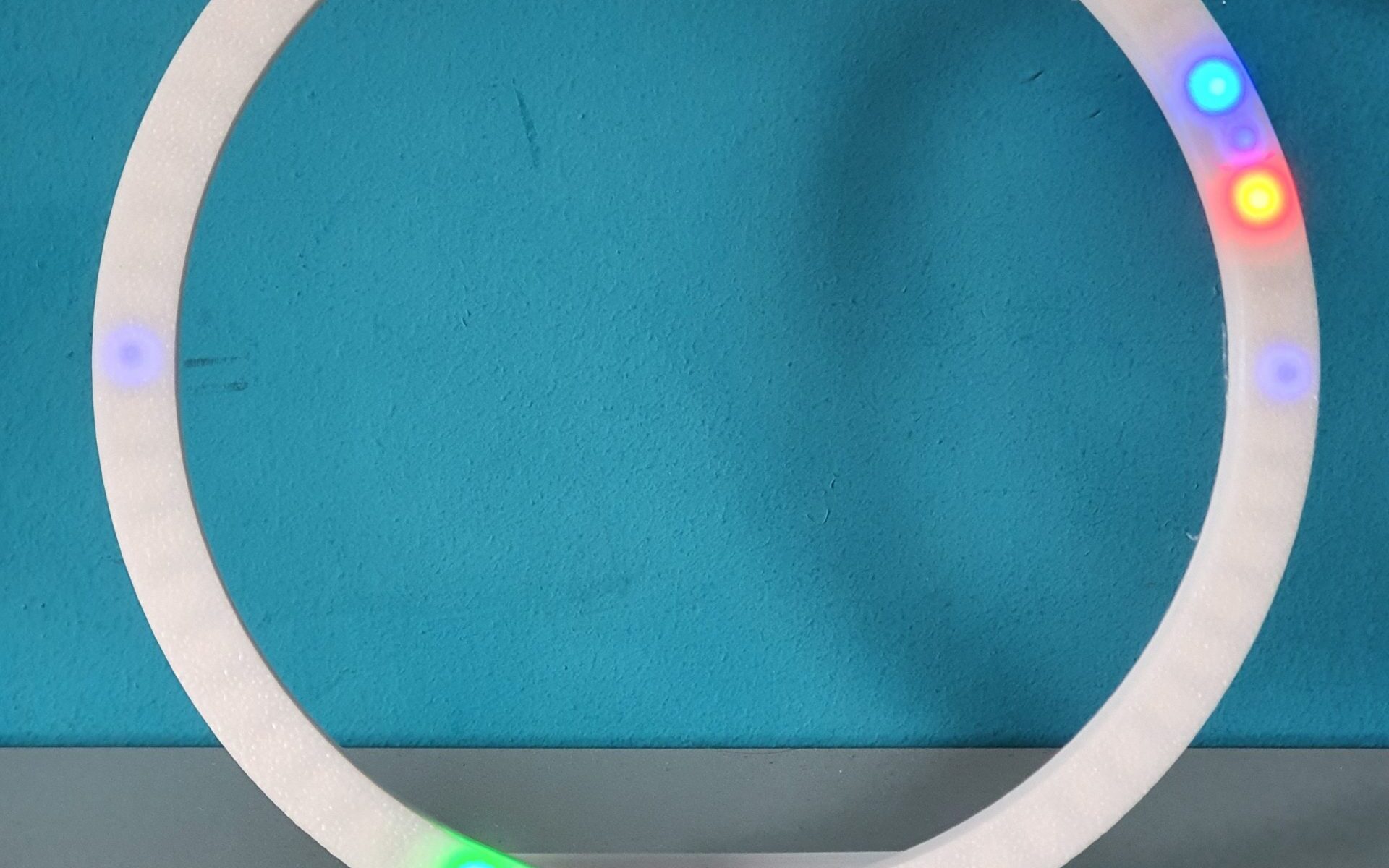
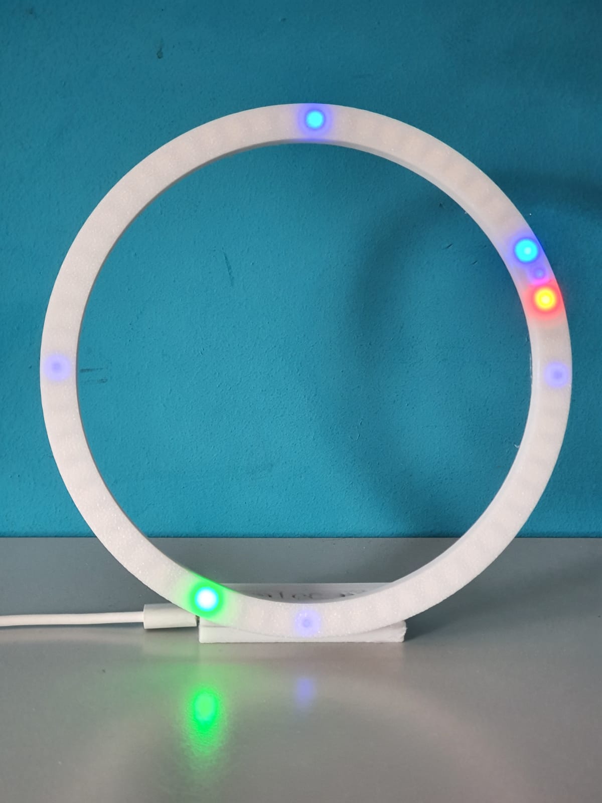
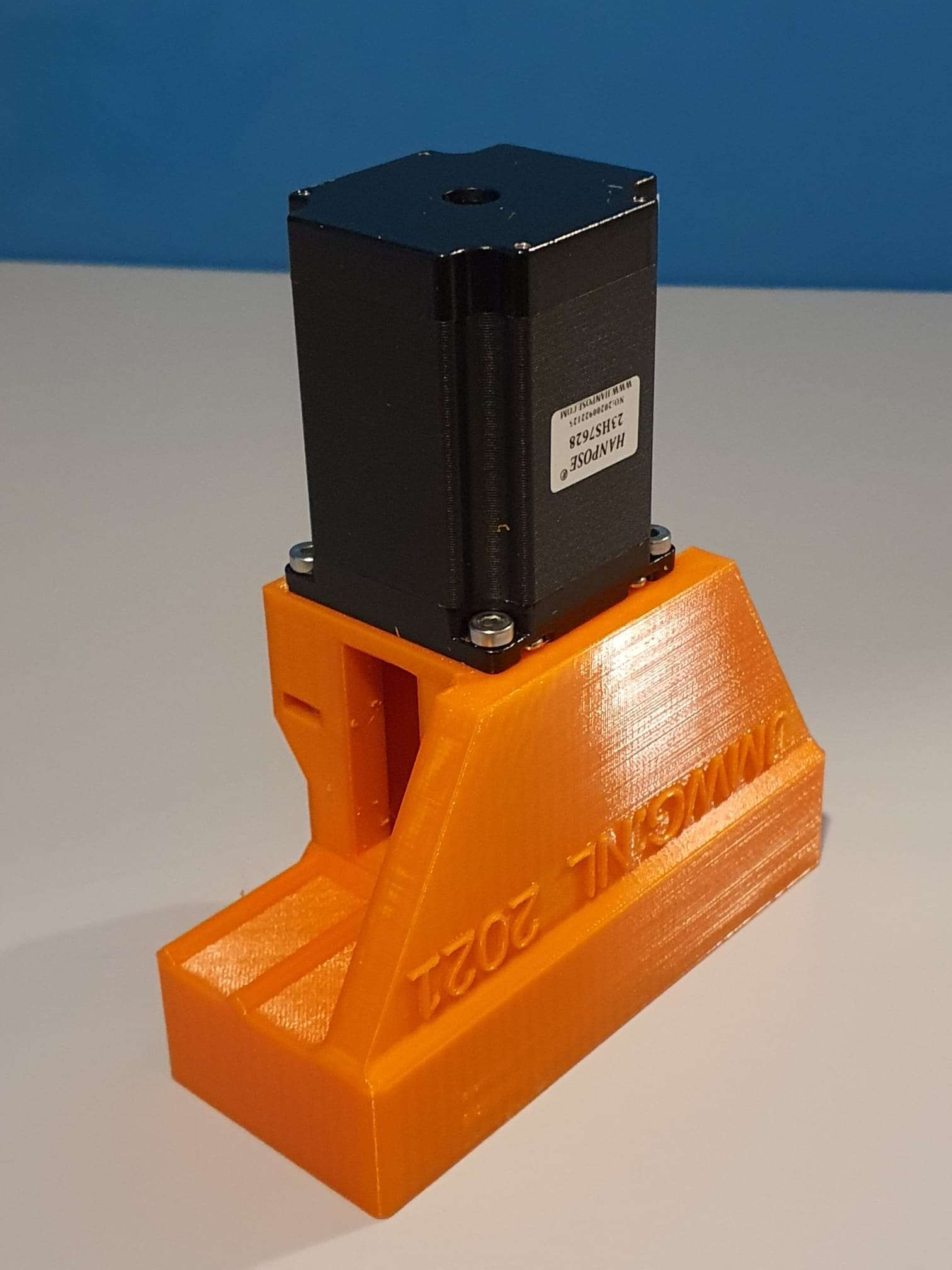
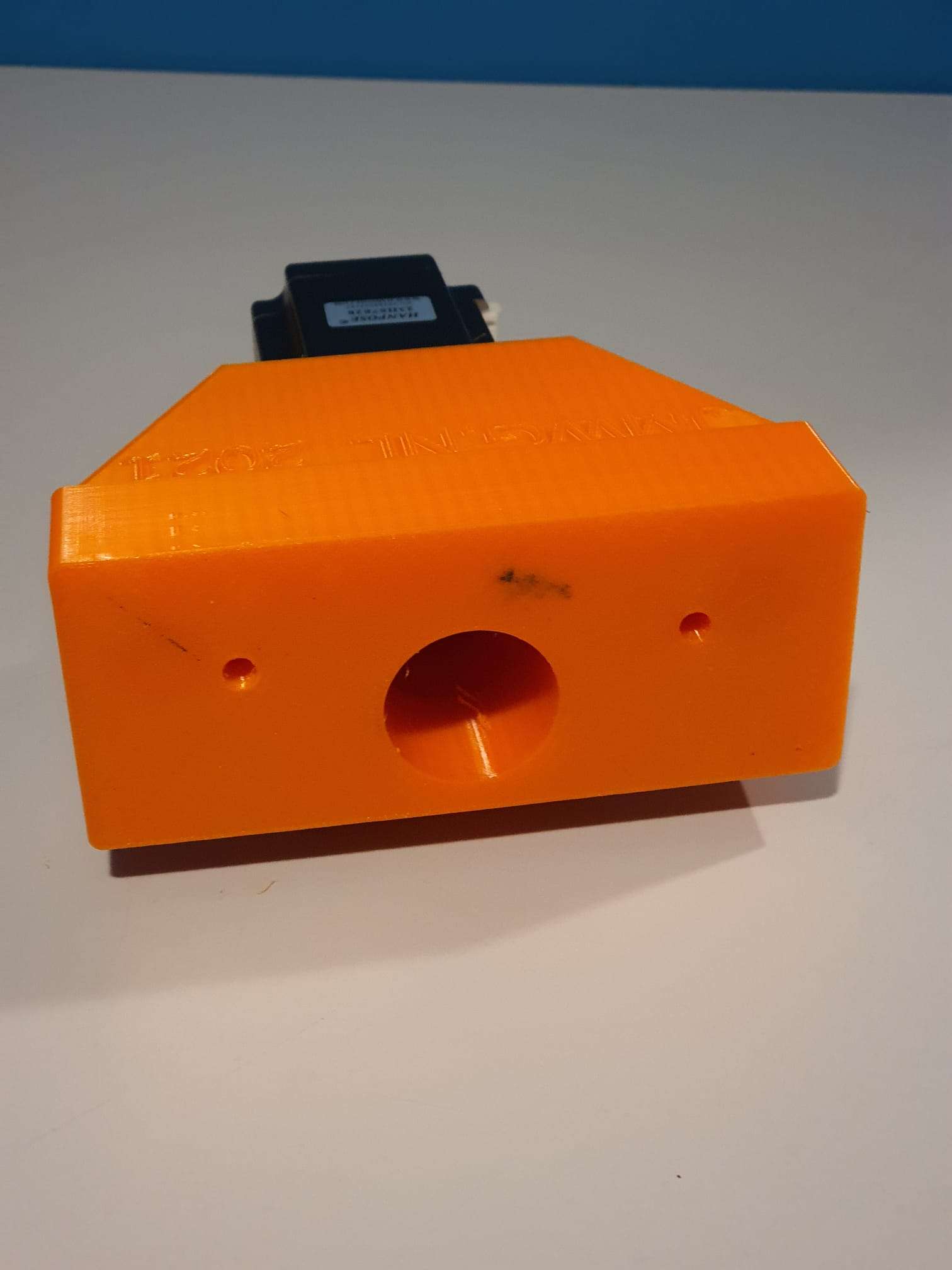
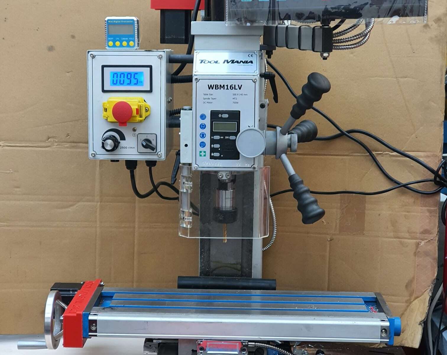
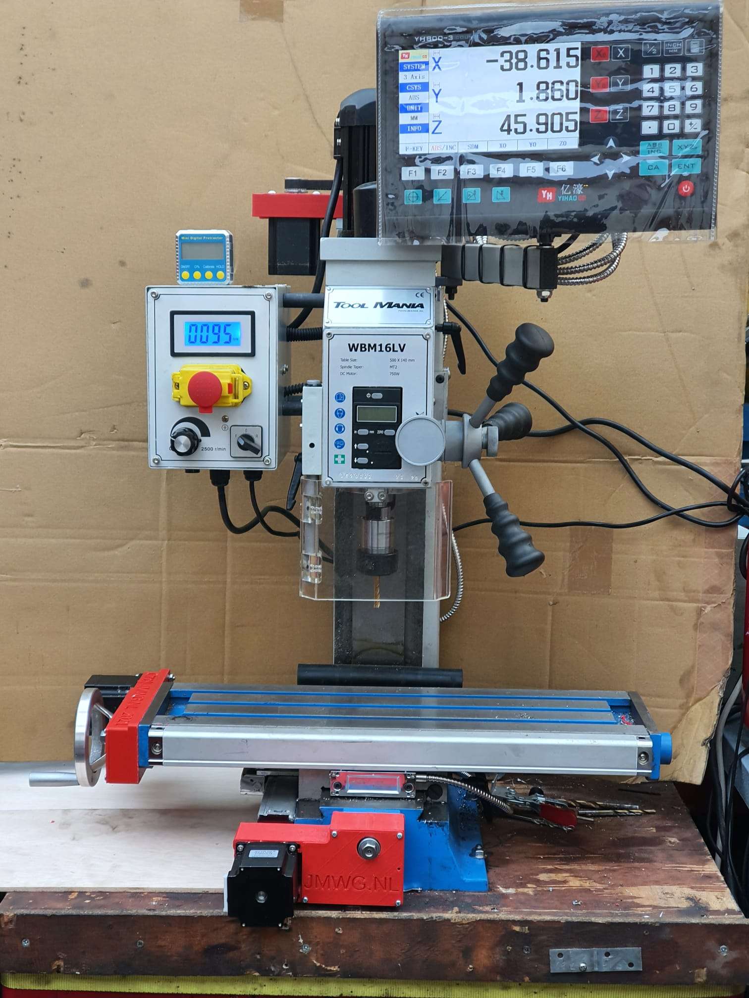
ABOVE: Circular clock, completed project, reading 05h:41m and crossing to 05h:42m. Red=hours, Green=minutes
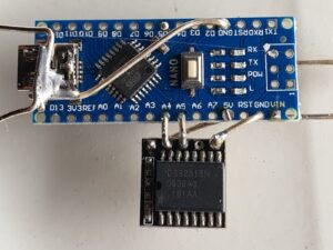
Above: Clock without case, with open components.
READ THIS ARTICLE IN ENGLISH
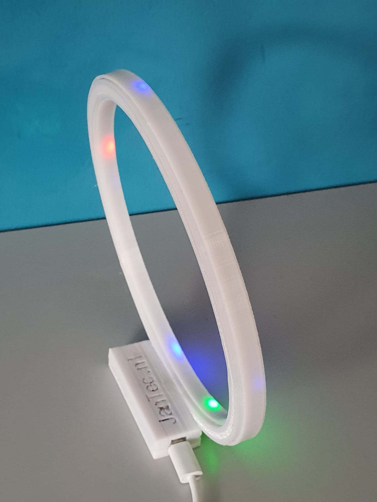
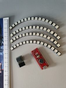
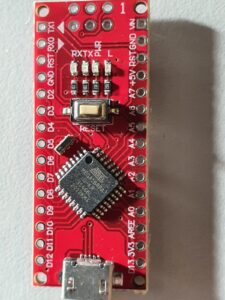
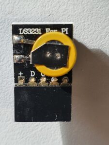
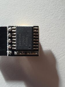
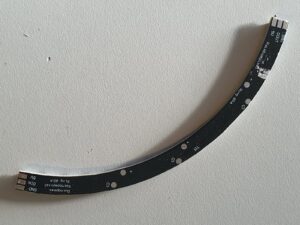
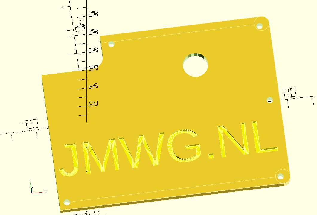
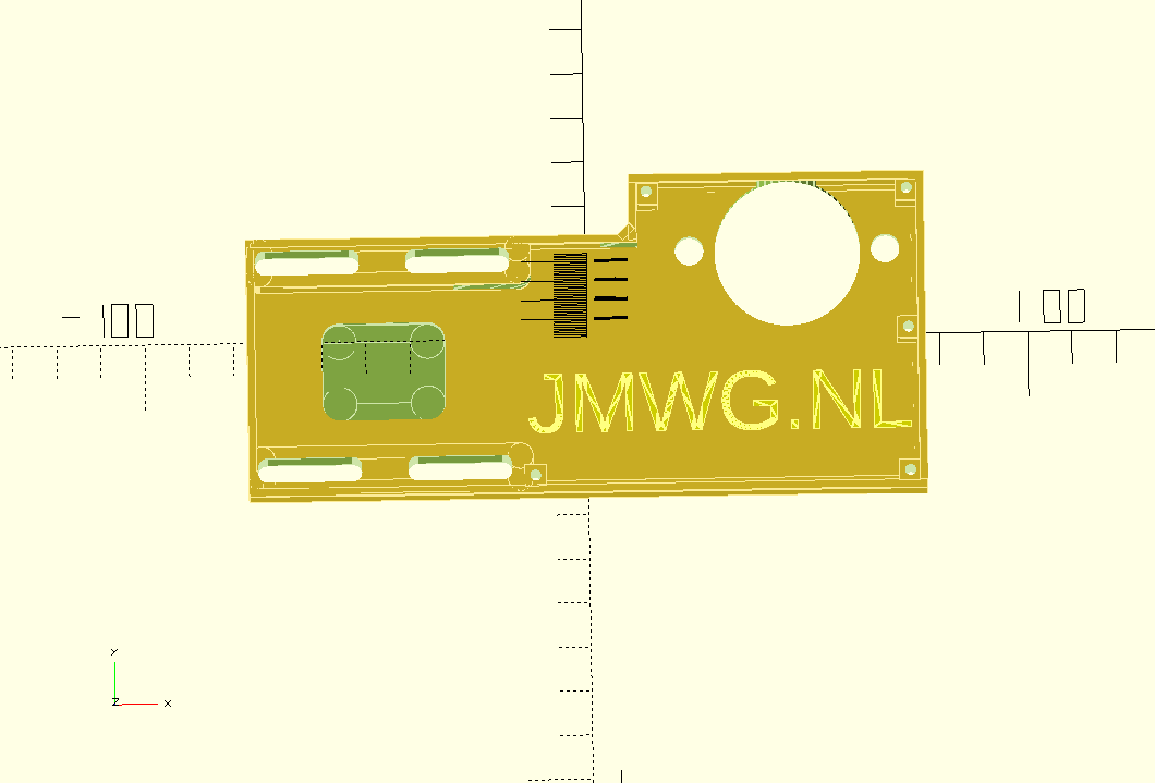
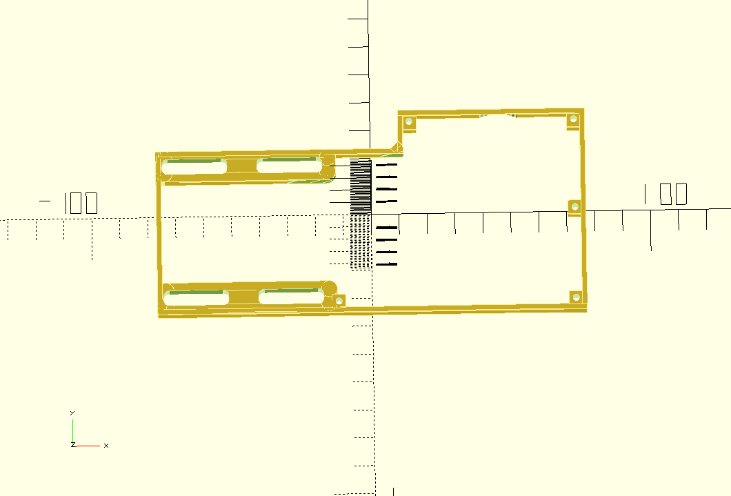
In de bovenstaande video zie je alle benodigde onderdelen voor de electronica. Een arduino Nano, een tijdmodule LS3231 met batterij back-up en een 4-delige ring met elk 15 stuks WS2812 LED’s die zorgen voor een 160mm 60 LED units klok. Je kunt hem bouwen als een open gebouwde unit zoals hierboven afgebeeld met draad of in een 3d printbare slanke behuizing die ik heb ontwikkeld. Zie de foto’s hieronder.
Voor het bouwen van deze mooie nauwkeurige klok, kun je mijn ontwerp files voor de behuizing gebruiken op elke 3d printer met een horizontale bed maat van minimaal 165x165mm.
Download de beide print STL’s OF van de Prusa gedeelde site waar ik deze ontwerpen heb geupload (zoek op de prusa site naar ws2812 circulaire arduino klok).
OF haal het STL bestand voor de VOORKANT van de klok van mijn website HIER
EN haal het STL bestand voor de ACHTERKANT van de klok van mijn website HIER
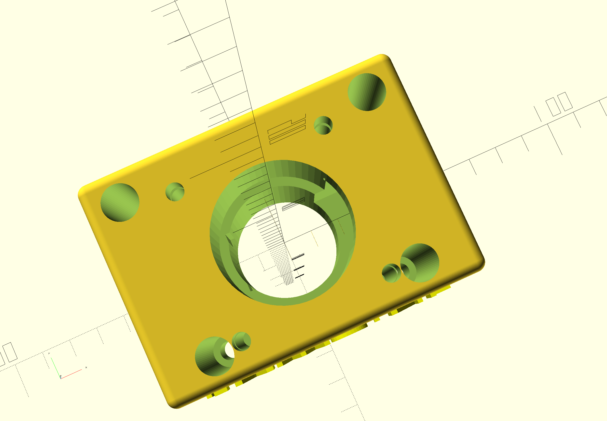
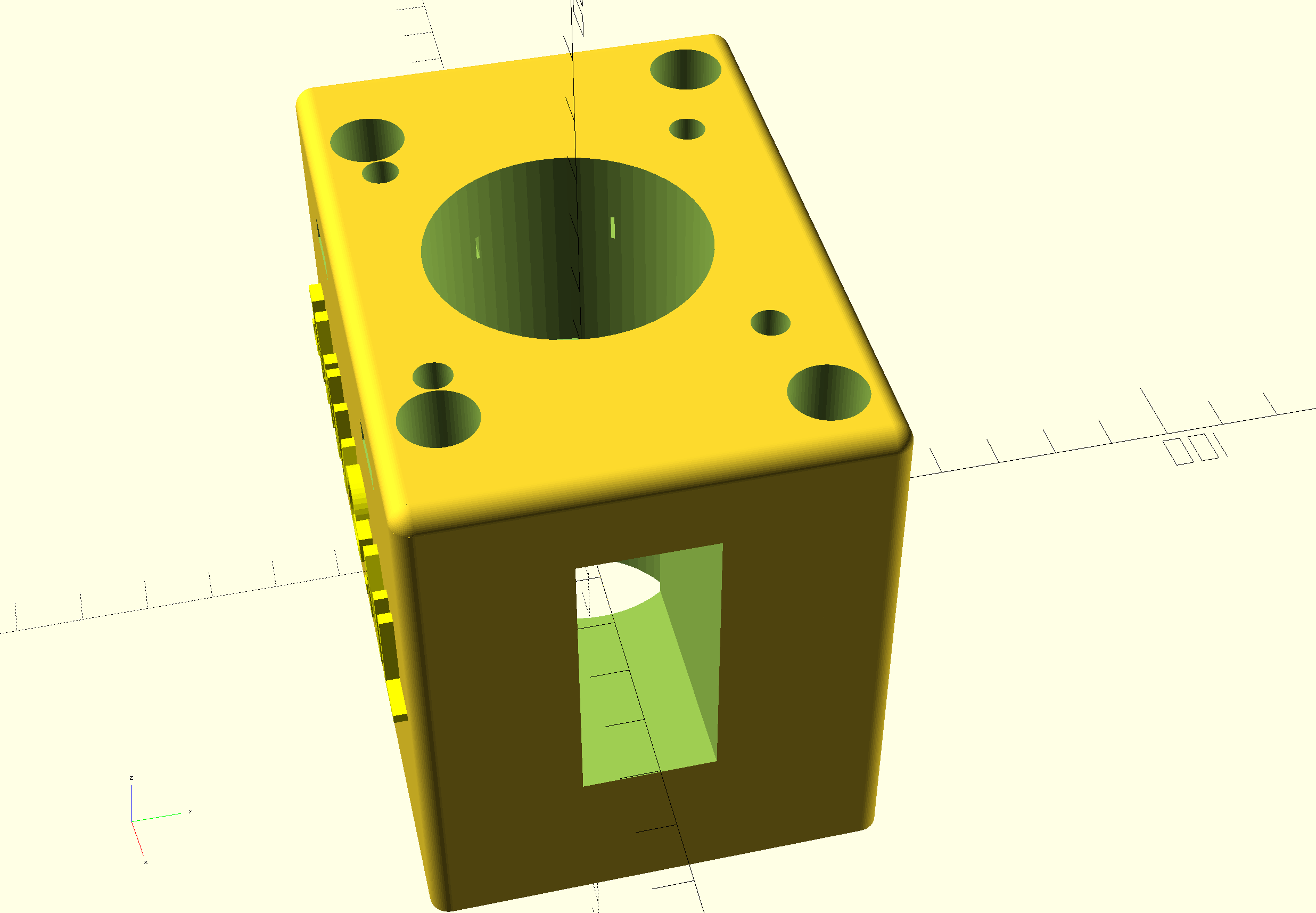
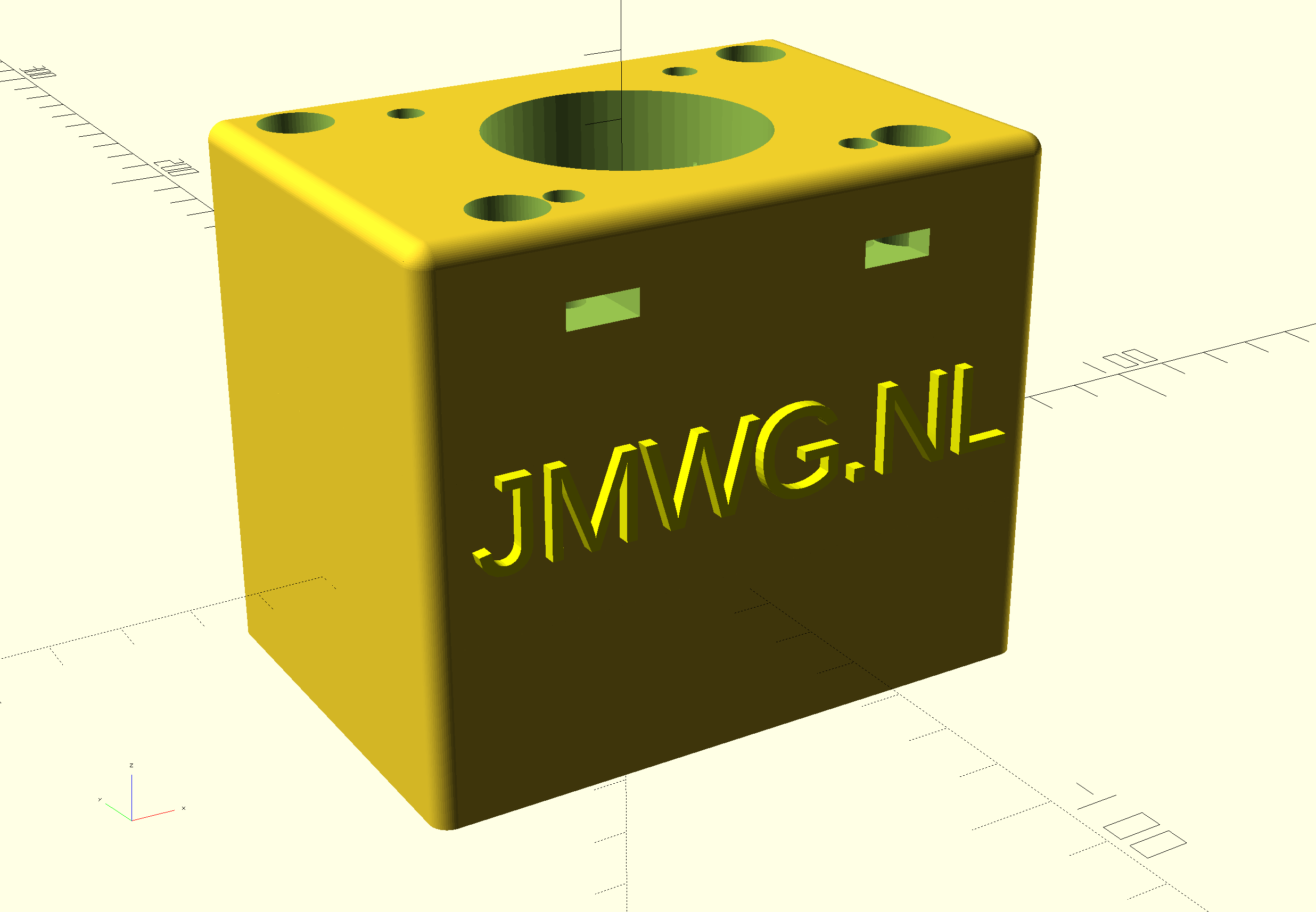
Eén STL is voor de achterkant en bevat de Nano box, de andere is voor de voorkant van de klok. Positioneer de achterste STL 180 graden (dus omhoog gaat omlaag) in uw slicer, zodat zowel de doos als de LED-behuizing op Z-0 niveau zijn, d.w.z. naar beneden gericht op hetzelfde horizontale niveau. De voorkant kan het best geprint worden met de platte kant naar beneden. ABS is niet aan te raden omdat het minder stijf is, maar zal waarschijnlijk ook werken. Voor mij werkt PETG of PLA het beste.
Gebruik wit filament voor het voorste deel, de achterkant kan elke kleur zijn die je wilt.
In de cirkel worden de 4 WS2812 LED segmenten in 1 volledige cirkel van ongeveer 160mm geplaatst.
Als je de elektronica aan de achterkant hebt aangesloten, schuift de voorkant er zo overheen. Geen lijm nodig. Maar de LED ring kan best op 4 plaatsen met een druppel hotglue aan de basis van de achterste behuizing gelijmd worden. Dit kun je het beste doen als je zeker weet dat alles goed werkt.
De LED onderdelen zijn verkrijgbaar op o.a. banggood , aliexpress en zo, zoek naar 60LED circle WS2812 die de 160 mm buitendiameter heeft.
Elke LED vertegenwoordigt een punt voor seconden, minuten of als uur indicator.
De kleuren bepalen de functie. Blauw wordt ook gebruikt als kwartier indicator met minder intensiteit, om een gevoel van positionering te hebben voor de andere LEDS als het donker is.
Kijk naar de video hierboven van het ‘open’ demonstratiemodel om te begrijpen hoe het werkt.
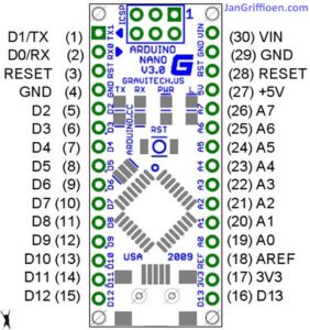
Hieronder vindt je de Arduino code voor de gebruikte Nano3, as-is. het werkt voor mij, en in de code vindt u ook alle benodigde elektrische aansluitingen en de specificaties van de gebruikte Time module.
Haal de Arduino code HIER
Wanneer aangesloten op je PC, kun je de Arduino programmeren en via de seriële interface kun je naderhand speciale instellingen van de klok wijzigen, zoals helderheid, speciale kwartierverlichtingsindicatoren, enzovoort. het staat allemaal in de code hieronder.
De aansturing kan via een seriële interface met de usb ingang van de Arduino, via een terminalprogramma zoals YAT of met de interface van het Arduino IDE programma.
De commando’s zijn:
f; fader UIT
F; fader AAN
m (getal); dim de 4 blauwe marker LED’s met waarde (getal)
S; synchroniseren met RTC tijd
s; synchroniseren met systeemtijd (computer)
t (tijd); systeemtijd veranderen in:
b; helderheid van alle niet-marker LED’s
Doneer a.j.b. $1 aan mijn paypal account als je (delen van) mijn ontwikkelde materialen gebruikt, zodat ik kan doorgaan met het delen van leuke dingen voor jou om te downloaden
Ik hoop dat alles goed gaat lukken!
Succes,
Jan


De Arduino code, te gebruiken voor het programmeren van de Arduino Nano3 is beschikbaar onderaan dit bericht als platte tekst om te importeren in een leeg arduino bestand (met kopiëren en plakken).
Zorg ervoor dat je alleen de bibliotheken en tijdmodule gebruikt die in de code zijn aangegeven! De gebruikte tijdmodule is van de betere generatie die de tijd zeer goed vasthoudt, ook in stand-by.
Gebruik voor het verbinden van de draden tussen de neopixel segmenten, de arduino en de tijdmodule een temperatuurgeregelde soldeerbout. Gebruik een ventilator als je aan het solderen bent en adem geen giftige gassen in tijdens het solderen.


De Arduino code is hieronder weergegeven, te importeren in Arduino IDE in een .ino bestand. Met de Arduino IDE moet je vervolgens de code compileren om de Arduino Nano geflasht te krijgen met het programma.
/**
* NeoClock
*
* Clock using 60 WS2812B/Neopixel LEDs and DS3231 RTC
* Small changes and updates made by jan Griffioen, Amsterdam Europe 2018-2021
* Libraries needed:
* * Adafruit NeoPixel (Library Manager) – Phil Burgess / Paint Your Dragon for Adafruit Industries – LGPL3
* *
* * Arduino Timezone Library (https://github.com/JChristensen/Timezone) – Jack Christensen – CC-BY-SA
* * Time Library (https://github.com/PaulStoffregen/Time) – Paul Stoffregen, Michael Margolis – LGPL2.1
*/
#include <Adafruit_NeoPixel.h>
#ifdef __AVR__
#include <avr/power.h>
#endif
#if defined(ESP8266)
#include <pgmspace.h>
#else
#include <avr/pgmspace.h>
#endif
/* for software wire use below
#include <SoftwareWire.h> // must be included here so that Arduino library object file references work
#include <RtcDS3231.h>
SoftwareWire myWire(SDA, SCL);
RtcDS3231<SoftwareWire> Rtc(myWire);
for software wire use above */
/* for normal hardware wire use below */
#include <Wire.h> // must be included here so that Arduino library object file references work
#include <RtcDS3231.h>
RtcDS3231<TwoWire> Rtc(Wire);
/* for normal hardware wire use above */
#include <TimeLib.h> //http://www.arduino.cc/playground/Code/Time
#include <Timezone.h> //https://github.com/JChristensen/Timezone
#include <EEPROM.h>
//Central European Time (Frankfurt, Paris)
TimeChangeRule CEST = {“CEST”, Last, Sun, Mar, 2, 120}; //Central European Summer Time
TimeChangeRule CET = {“CET “, Last, Sun, Oct, 3, 60}; //Central European Standard Time
Timezone CE(CEST, CET);
TimeChangeRule *tcr; //pointer to the time change rule, use to get the TZ abbrev
time_t utc;
#define PIN 5
unsigned long lastMillis = millis();
byte dimmer = 0x88;
byte hmark = 0;
byte ohour=0;
byte ominute=0;
byte osecond=0;
boolean fader=true;
Adafruit_NeoPixel strip = Adafruit_NeoPixel(60, PIN, NEO_GRB + NEO_KHZ800);
void setup() {
Serial.begin(57600);
strip.begin();
strip.setBrightness(50);
// Some example procedures showing how to display to the pixels:
// colorWipe(strip.Color(255, 0, 0), 50); // Red
//colorWipe(strip.Color(0, 255, 0), 50); // Green
//colorWipe(strip.Color(0, 0, 255), 50); // Blue
//colorWipe(strip.Color(0, 0, 0, 255), 50); // White RGBW
// Send a theater pixel chase in…
//theaterChase(strip.Color(127, 127, 127), 50); // White
theaterChase(strip.Color(127, 0, 0), 50); // Red
//theaterChase(strip.Color(0, 0, 127), 50); // Blue
//rainbow(20);
rainbowCycle(2);
//theaterChaseRainbow(50);
strip.clear();
strip.show(); // Initialize all pixels to ‘off’
Rtc.Begin();
Rtc.Enable32kHzPin(false);
Rtc.SetSquareWavePin(DS3231SquareWavePin_ModeNone);
if (!Rtc.GetIsRunning())
{
Serial.println(“Rtc was not actively running, starting now”);
Rtc.SetIsRunning(true);
}
if (!Rtc.IsDateTimeValid())
{
// Common Cuases:
// 1) the battery on the device is low or even missing and the power line was disconnected
Serial.println(“Rtc lost confidence in the DateTime!”);
}
byte eechk = EEPROM.read(0);
if(eechk == 0xAA) { //Assume this is our config and not a fresh chip
dimmer = EEPROM.read(1);
hmark = EEPROM.read(2);
fader = EEPROM.read(3);
}
timeSync();
}
void calcTime(void) {
utc = now();
CE.toLocal(utc, &tcr);
ohour = hour(utc);
ominute = minute(utc);
if(osecond != second(utc)) {
osecond = second(utc);
lastMillis = millis();
if(ominute == 0 && osecond == 0) {
//Every hour
timeSync();
}
}
}
void addPixelColor(byte pixel, byte color, byte brightness) {
color *= 8;
uint32_t acolor = brightness;
acolor <<= color;
uint32_t ocolor = strip.getPixelColor(pixel);
ocolor |= acolor;
strip.setPixelColor(pixel, ocolor);
}
void drawClock(byte h, byte m, byte s) {
strip.clear();
addPixelColor(m, 1, dimmer);
if(hmark > 0) {
for(byte i = 0; i<12; i++) {
addPixelColor((5*i), 2, hmark);
}
}
h %= 12;
h *= 5;
h += (m/12);
addPixelColor(h, 2, dimmer);
// 0x RR GG BB
if(fader) {
byte dim_s1 = dimmer;
byte dim_s2 = 0;
byte px_s2 = s+1;
if(px_s2 >= 60) px_s2 = 0;
unsigned long curMillis = millis()-lastMillis;
if(curMillis < 250) {
dim_s2 = 0;
dim_s1 = dimmer;
}else{
dim_s2 = map(curMillis, 250, 1000, 0, dimmer);
dim_s1 = dimmer – map(curMillis, 250, 1000, 0, dimmer);
}
// Add blue low intensity dots for 12(0),3, 6 and 9 O’çlock to verify where the clock is positioned..
addPixelColor(15, 128, 10);
addPixelColor(30, 128, 10);
addPixelColor(45, 128, 10);
addPixelColor(0, 128, 40);
addPixelColor(s, 0, dim_s1);
addPixelColor(px_s2, 0, dim_s2);
}else{
addPixelColor(s, 0, dimmer);
}
// add a background color
// setBrightness(Serial.parseInt());
// uint16_t j;
// for(j=0; j<60; j++) { // 1 cycles of colors on wheel
// strip.setPixelColor(j, Wheel(((j * 256 / strip.numPixels()) + j) & 255));
// }
strip.show();
}
byte rounds = 0;
void loop() {
calcTime();
if(rounds++ > 100) {
Serial.print(ohour);
Serial.print(“:”);
Serial.print(ominute);
Serial.print(“:”);
Serial.print(osecond);
Serial.println(“(C)JG-2020”);
rounds = 0;
}
//rainbow(21);
if (osecond == 59){theaterChase(strip.Color(0, 0, 127), 40); }// Blue; }
//if (ominute == 59 AND osecond == 59){theaterChase(strip.Color(0, 127, 0), 50); }// Green}
//if (ohour == 11 AND ominute == 59 AND osecond == 59){theaterChase(strip.Color(127, 127, 0), 50); }// Green}
else {drawClock(ohour,ominute,osecond);}
delay(10);
chkSer();
}
void timeSync(void) {
RtcDateTime dt = Rtc.GetDateTime();
setTime(dt.Hour(),dt.Minute(),dt.Second(),dt.Day(),dt.Month(),dt.Year());
Serial.print(“Synced to: “);
Serial.print(dt.Year());
Serial.print(“-“);
Serial.print(dt.Month());
Serial.print(“-“);
Serial.print(dt.Day());
Serial.print(“-“);
Serial.print(dt.Hour());
Serial.print(“-“);
Serial.print(dt.Minute());
Serial.print(“-“);
Serial.println(dt.Second());
}
void timeSave(void) {
utc = now();
RtcDateTime store = RtcDateTime(year(utc), month(utc), day(utc), hour(utc), minute(utc), second(utc));
Rtc.SetDateTime(store);
Serial.print(“Synced to: “);
Serial.print(year(utc));
Serial.print(“-“);
Serial.print(month(utc));
Serial.print(“-“);
Serial.print(day(utc));
Serial.print(“-“);
Serial.print(hour(utc));
Serial.print(“-“);
Serial.print(minute(utc));
Serial.print(“-“);
Serial.println(second(utc));
}
void setBrightness(byte brightness) {
dimmer = brightness;
}
void chkSer(void) {
unsigned int iy;
byte im,id,iH,iM,iS;
if(!Serial.available()) return;
switch(Serial.read()) {
case ‘b’:
setBrightness(Serial.parseInt());
Serial.print(F(“Brightness changed to: “));
Serial.println(dimmer);
EEPROM.put(0, 0xAA);
EEPROM.put(1, dimmer);
break;
case ‘t’:
iy = Serial.parseInt();
im = Serial.parseInt();
id = Serial.parseInt();
iH = Serial.parseInt();
iM = Serial.parseInt();
iS = Serial.parseInt();
setTime(iH,iM,iS,id,im,iy);
Serial.println(F(“System time changed”));
break;
case ‘f’:
fader = false;
EEPROM.put(0, 0xAA);
EEPROM.put(3, 0);
Serial.println(F(“Fader off”));
break;
case ‘F’:
fader = true;
EEPROM.put(0, 0xAA);
EEPROM.put(3, 1);
Serial.println(F(“Fader on”));
break;
case ‘m’:
hmark = Serial.parseInt();
EEPROM.put(0, 0xAA);
EEPROM.put(2, hmark);
Serial.println(F(“HMark changed”));
break;
case ‘s’:
timeSync();
Serial.println(F(“Synced RTC to System”));
break;
case ‘S’:
timeSave();
Serial.println(F(“Synced System to RTC”));
break;
default:
Serial.println(‘?’);
}
}
// Fill the dots one after the other with a color
void colorWipe(uint32_t c, uint8_t wait) {
for(uint16_t i=0; i<strip.numPixels(); i++) {
strip.setPixelColor(i, c);
strip.show();
delay(wait);
}
}
void rainbow(uint8_t wait) {
uint16_t i, j;
for(j=0; j<256; j++) {
for(i=0; i<strip.numPixels(); i++) {
strip.setPixelColor(i, Wheel((i+j) & 25));//255
}
strip.show();
delay(wait);
}
}
// Slightly different, this makes the rainbow equally distributed throughout
void rainbowCycle(uint8_t wait) {
uint16_t i, j;
for(j=0; j<256*5; j++) { // 5 cycles of all colors on wheel
for(i=0; i< strip.numPixels(); i++) {
strip.setPixelColor(i, Wheel(((i * 256 / strip.numPixels()) + j) & 255));
}
strip.show();
delay(wait);
}
}
//Theatre-style crawling lights.
void theaterChase(uint32_t c, uint8_t wait) {
for (int j=0; j<4; j++) { //do 4 cycles of chasing
for (int q=0; q < 3; q++) {
for (uint16_t i=0; i < strip.numPixels(); i=i+3) {
strip.setPixelColor(i+q, c); //turn every third pixel on
}
strip.show();
delay(wait);
for (uint16_t i=0; i < strip.numPixels(); i=i+3) {
strip.setPixelColor(i+q, 0); //turn every third pixel off
}
}
}
}
//Theatre-style crawling lights with rainbow effect
void theaterChaseRainbow(uint8_t wait) {
for (int j=0; j < 256; j++) { // cycle all 256 colors in the wheel
for (int q=0; q < 3; q++) {
for (uint16_t i=0; i < strip.numPixels(); i=i+3) {
strip.setPixelColor(i+q, Wheel( (i+j) % 255)); //turn every third pixel on
}
strip.show();
delay(wait);
for (uint16_t i=0; i < strip.numPixels(); i=i+3) {
strip.setPixelColor(i+q, 0); //turn every third pixel off
}
}
}
}
// Input a value 0 to 255 to get a color value.
// The colours are a transition r – g – b – back to r.
uint32_t Wheel(byte WheelPos) {
WheelPos = 255 – WheelPos;
if(WheelPos < 85) {
return strip.Color(255 – WheelPos * 3, 0, WheelPos * 3);
}
if(WheelPos < 170) {
WheelPos -= 85;
return strip.Color(0, WheelPos * 3, 255 – WheelPos * 3);
}
WheelPos -= 170;
return strip.Color(WheelPos * 3, 255 – WheelPos * 3, 0);
}

