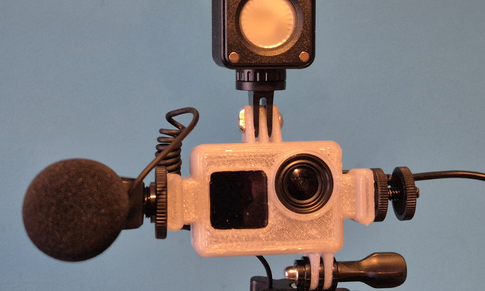
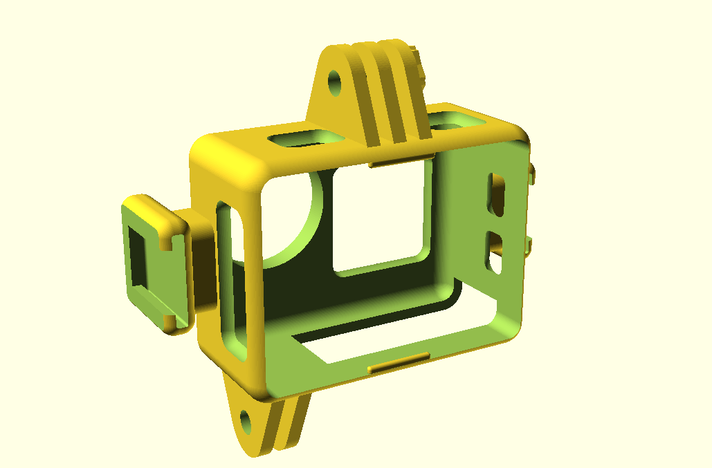
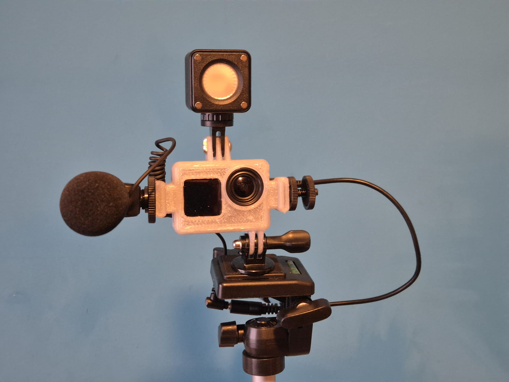
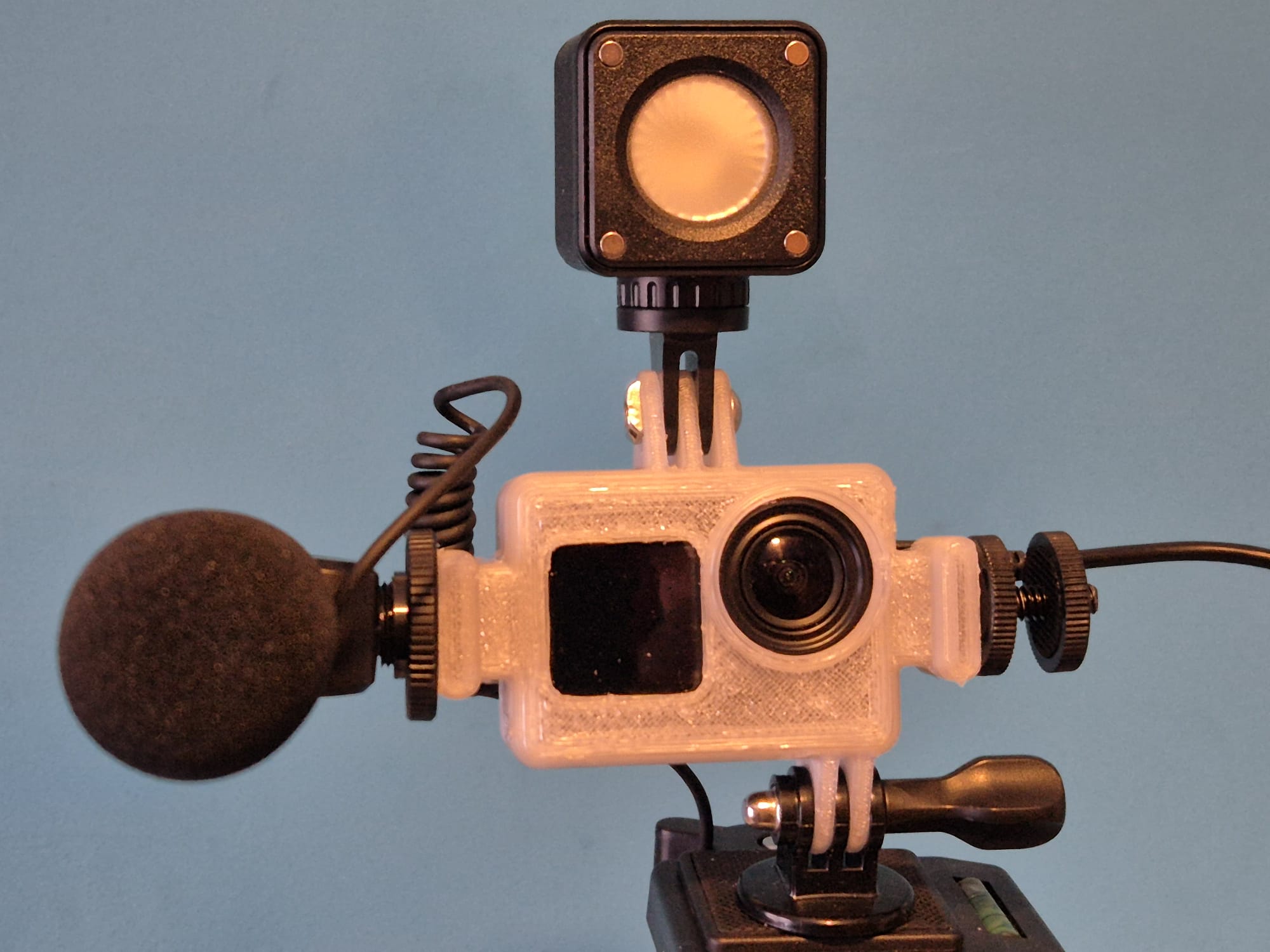
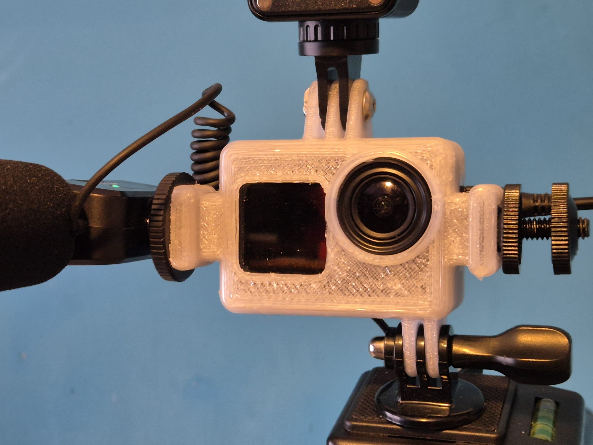
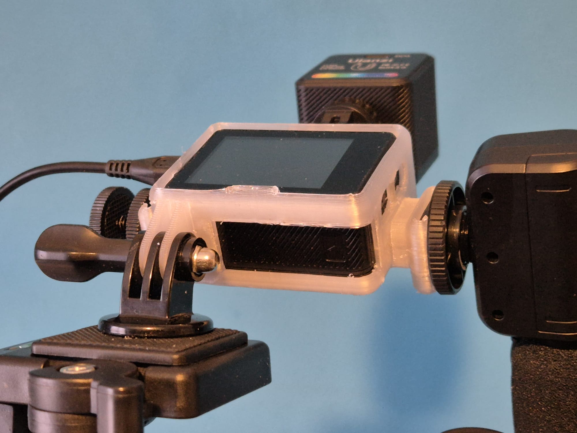
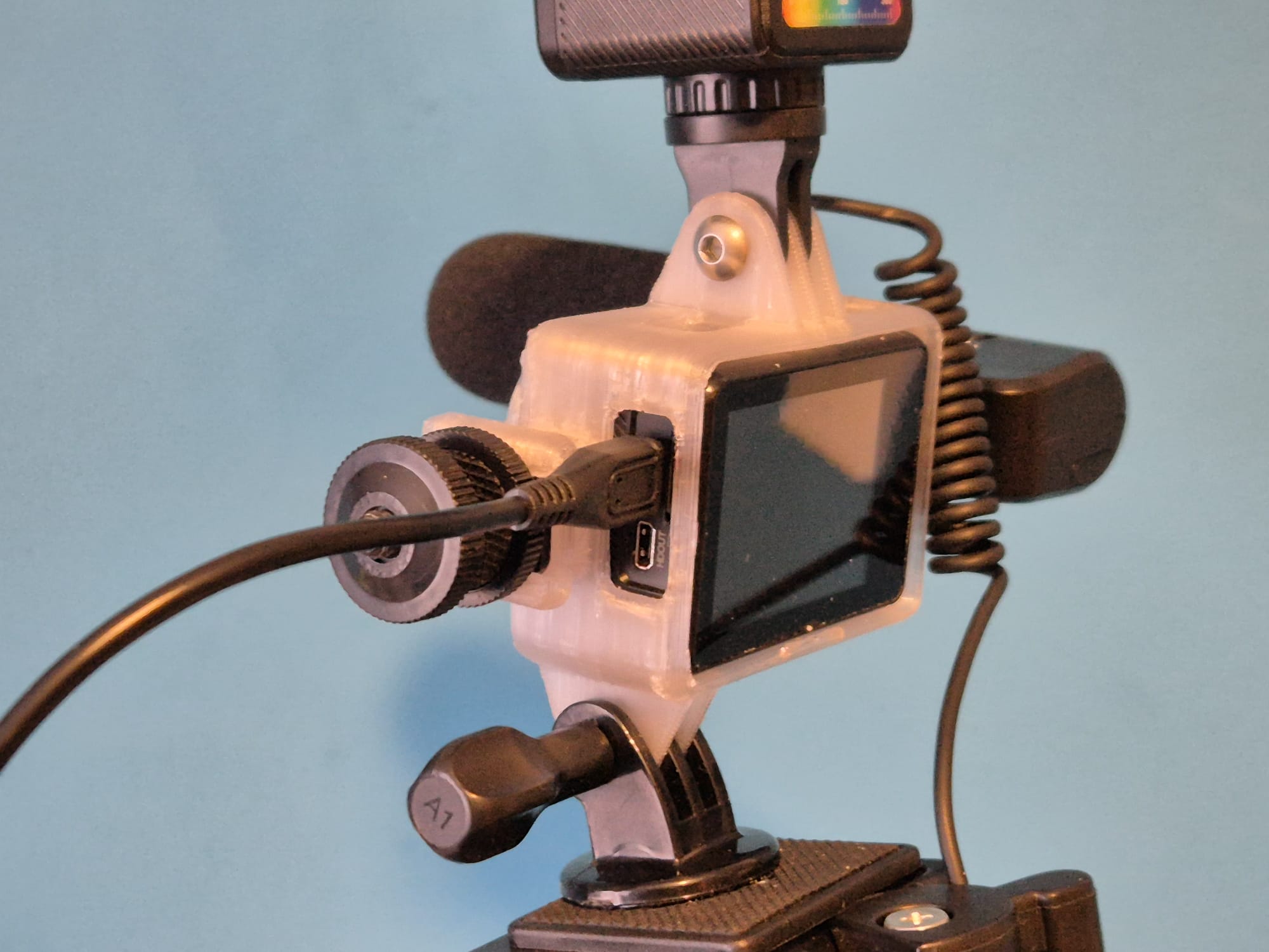
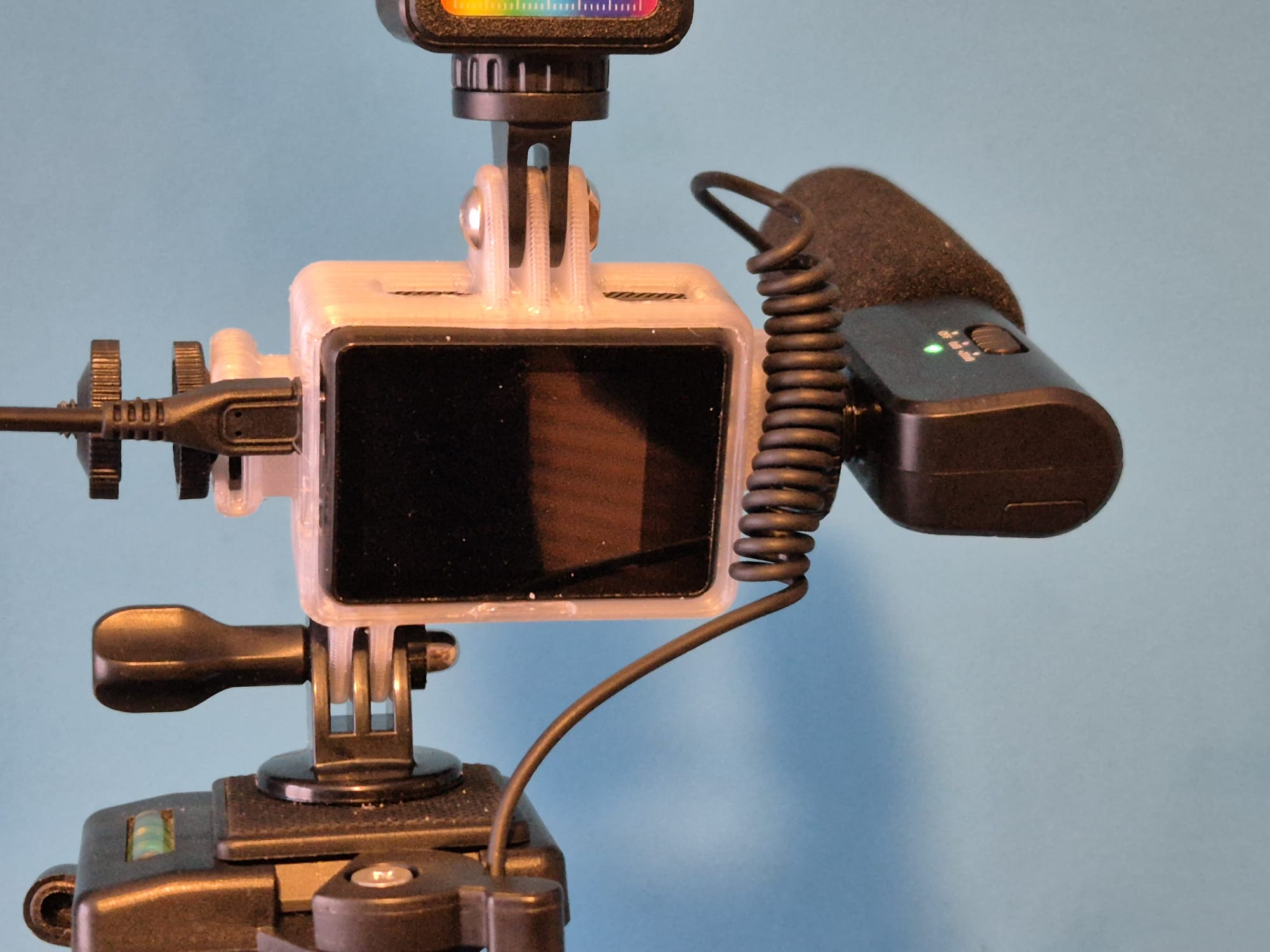
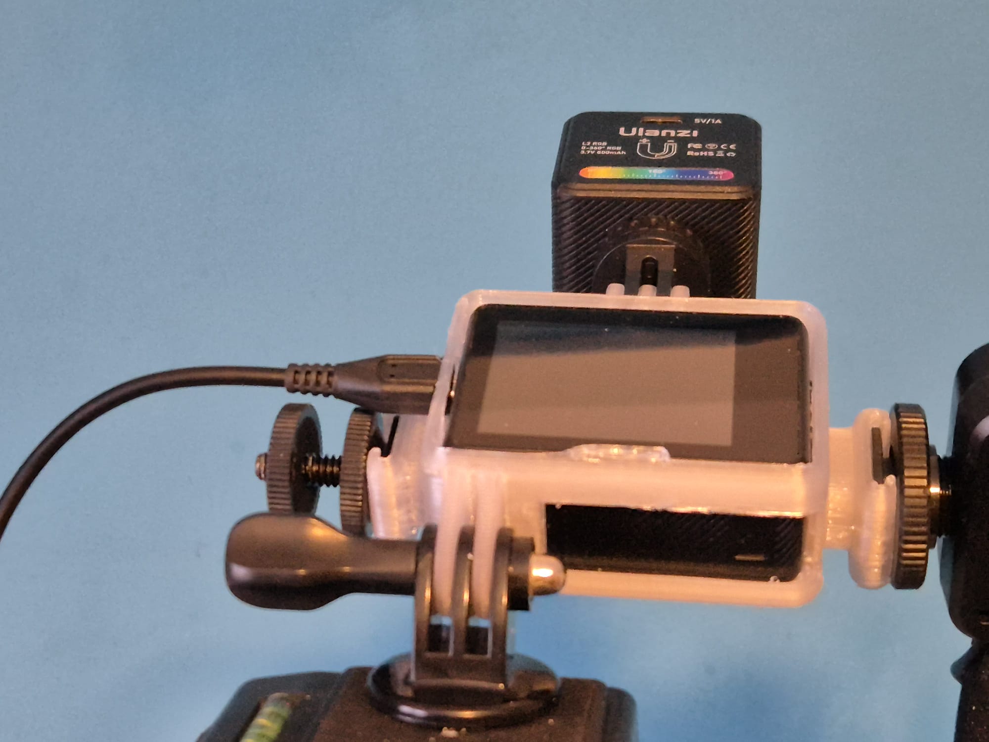
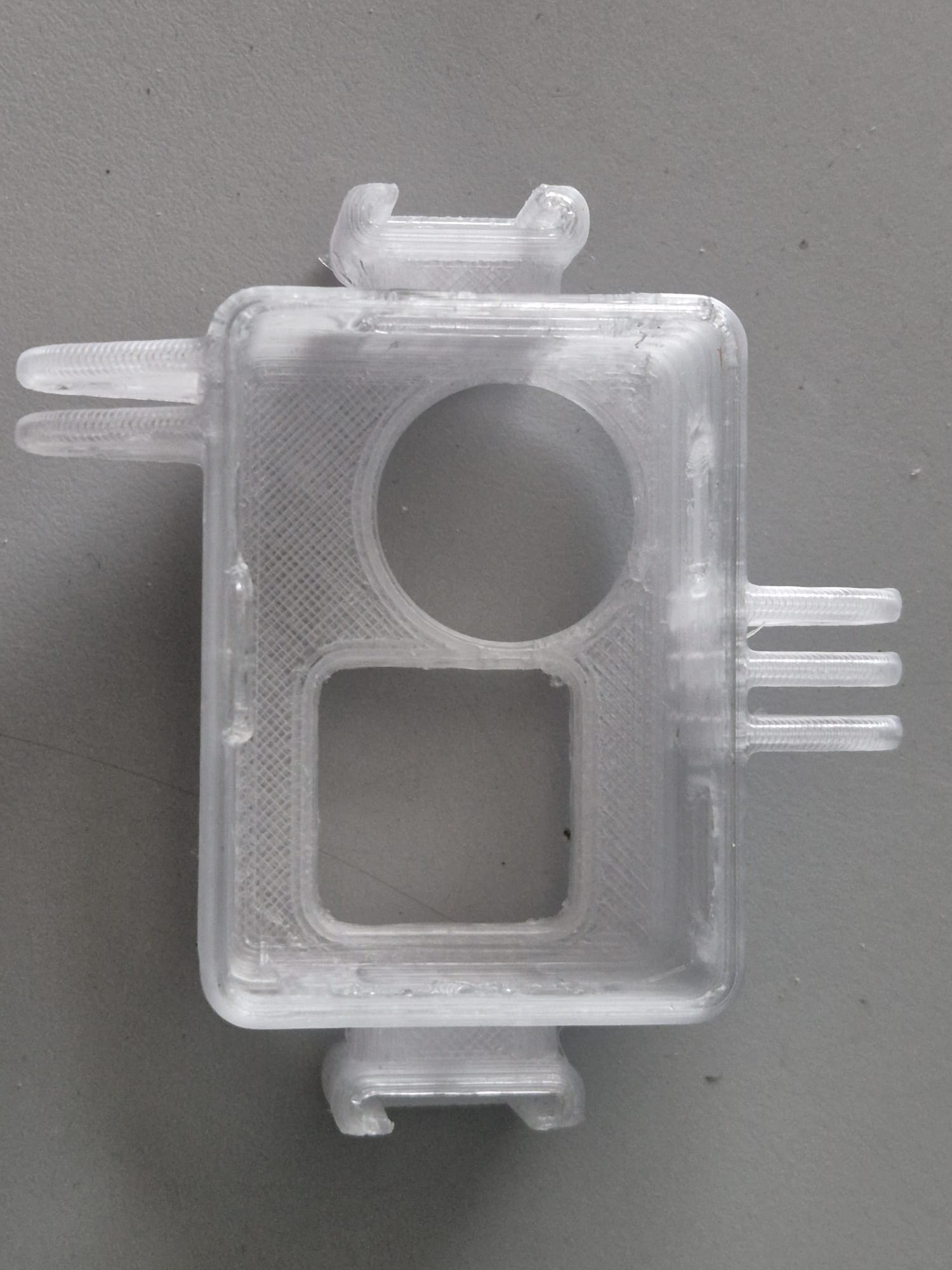
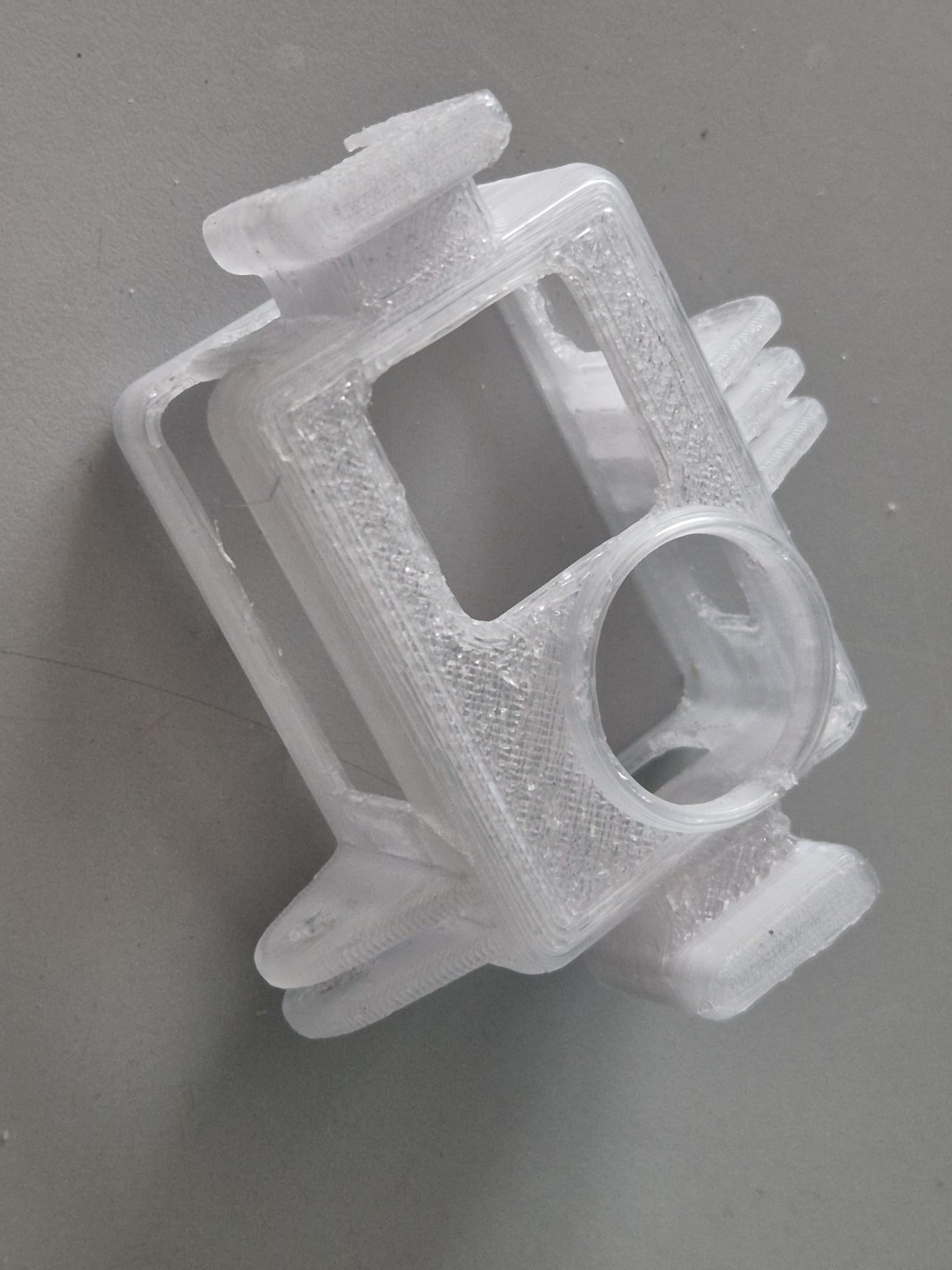
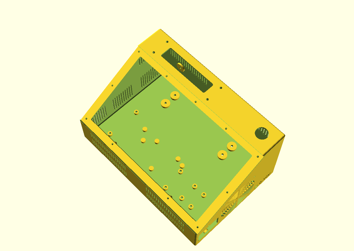
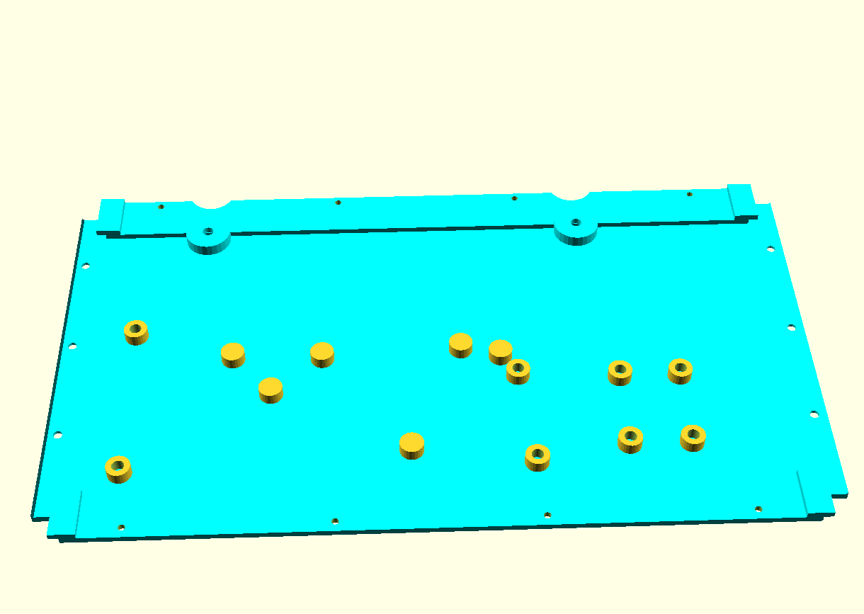
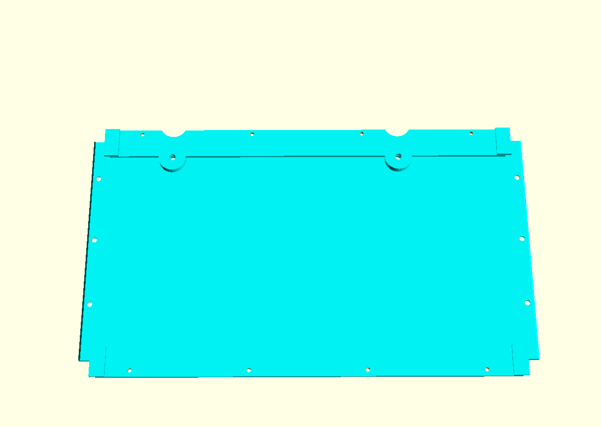
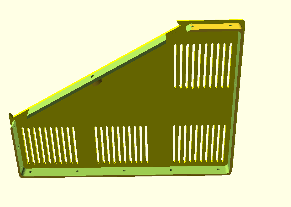
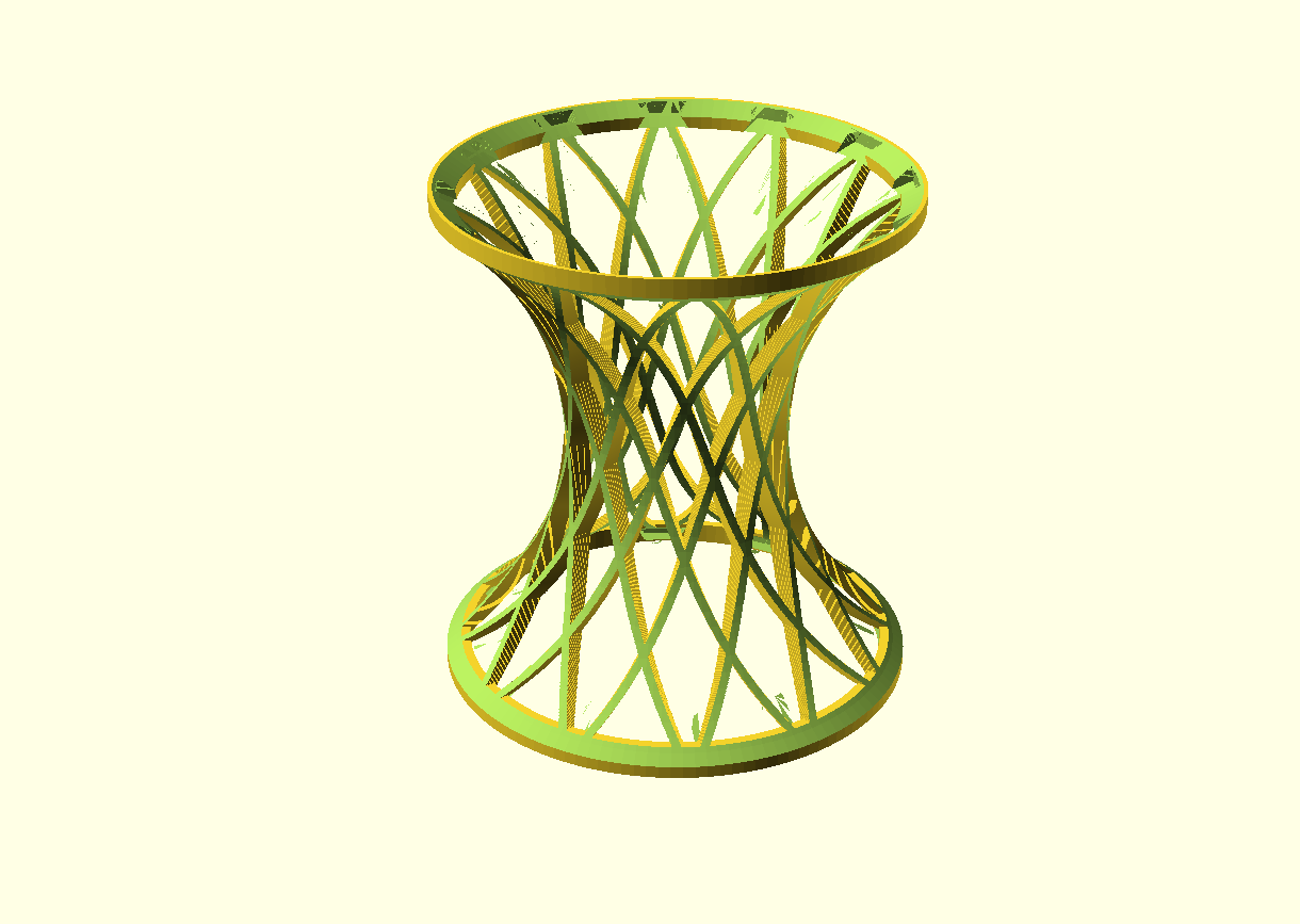
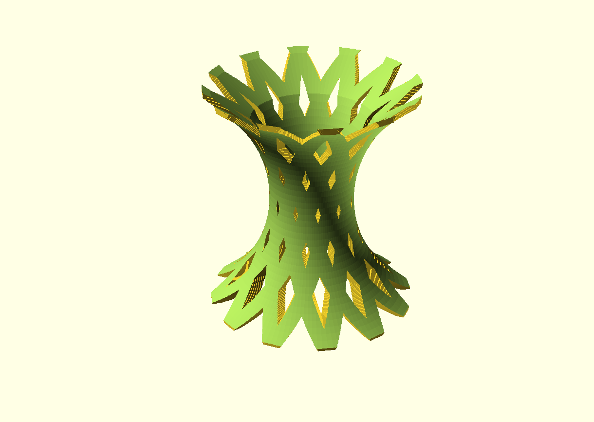
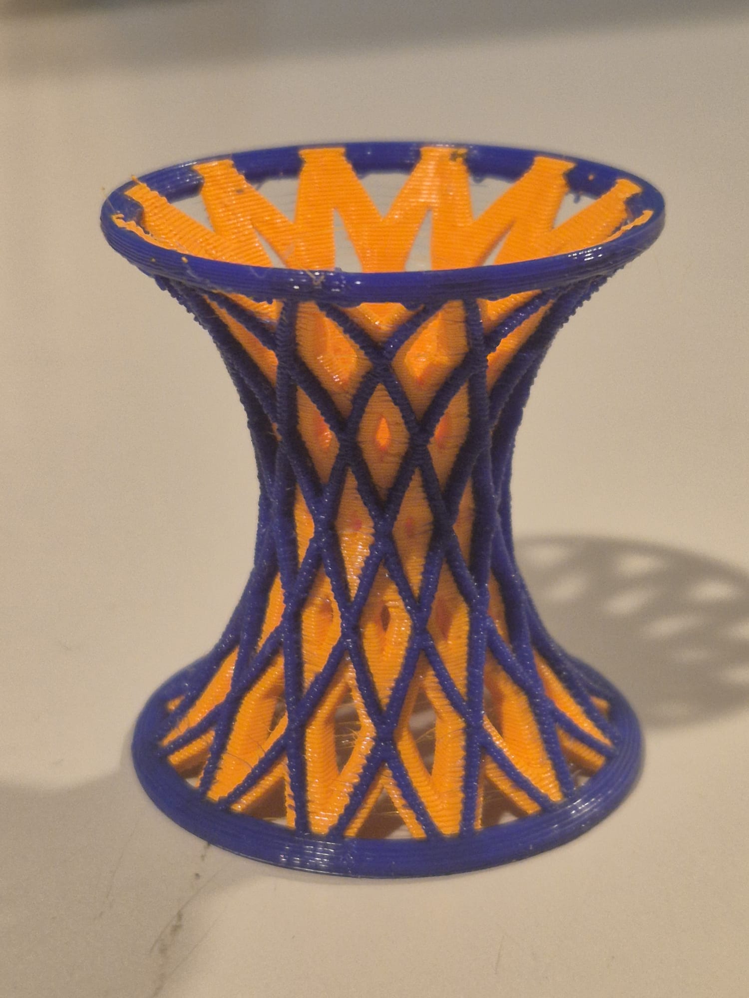
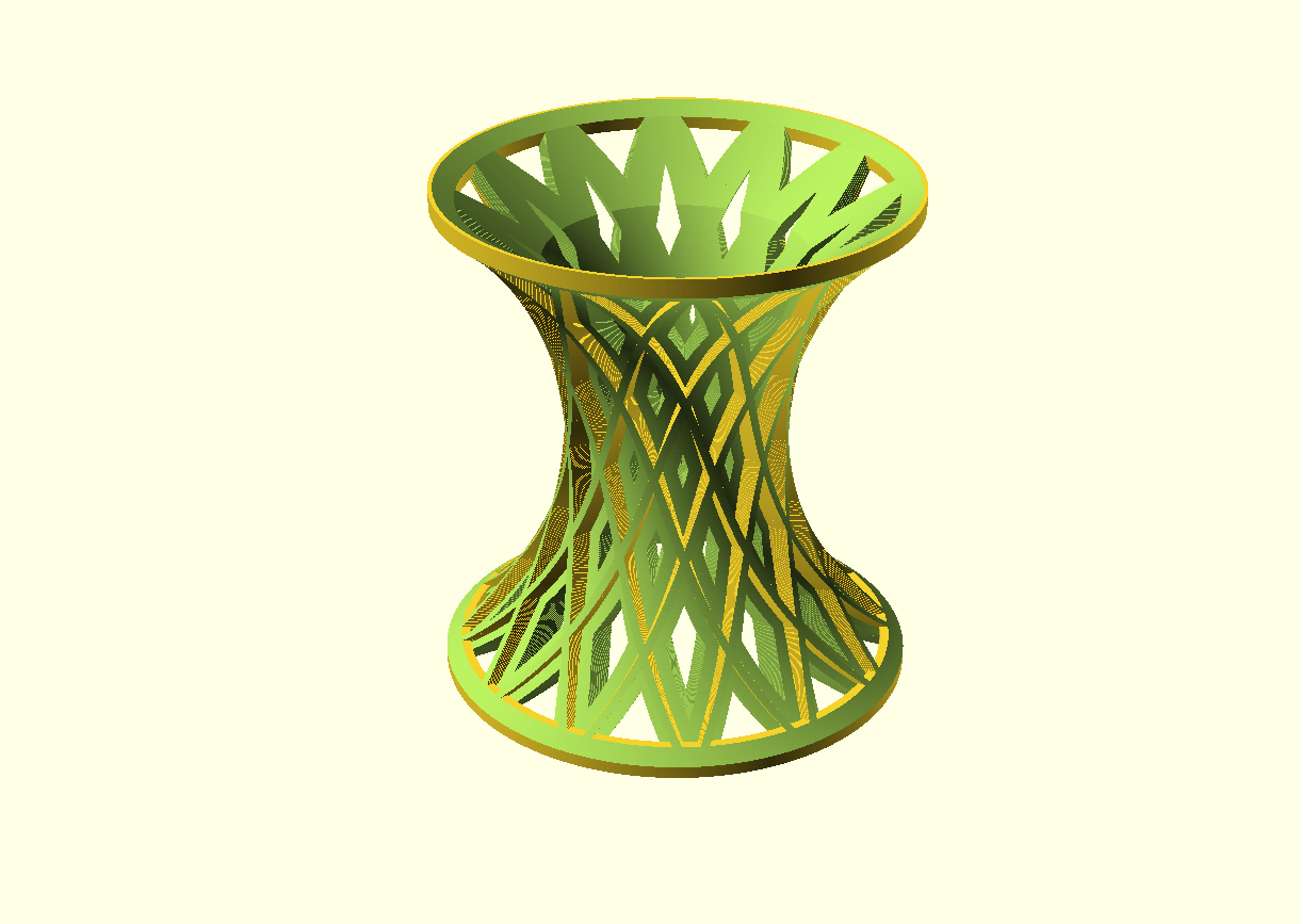
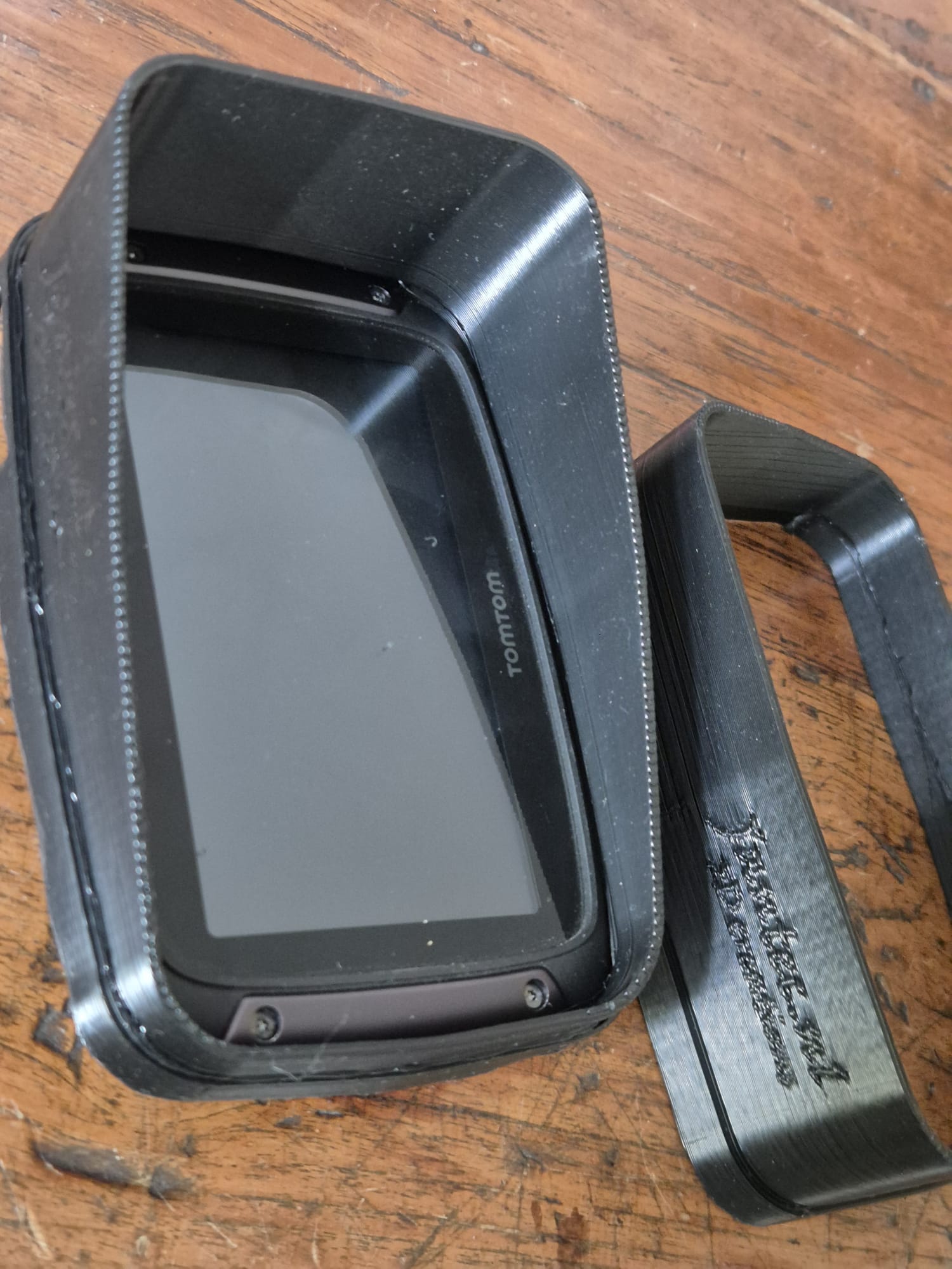
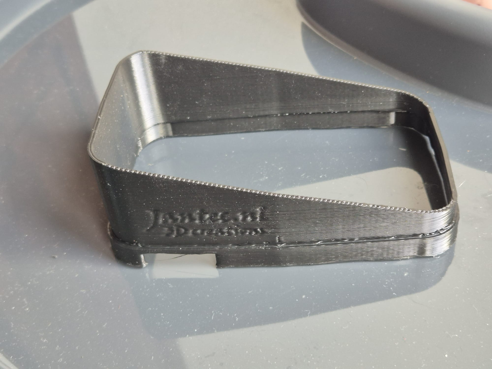
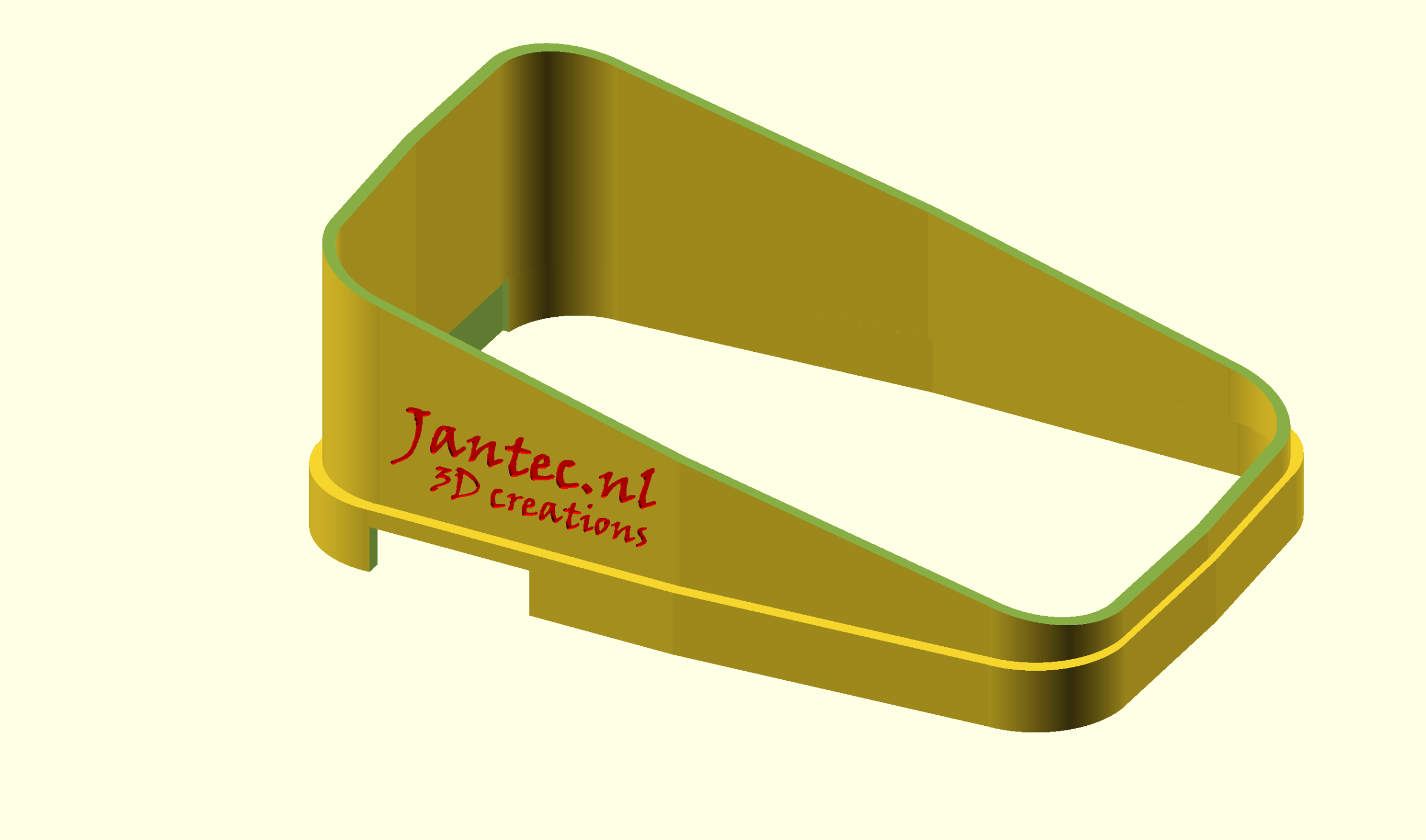
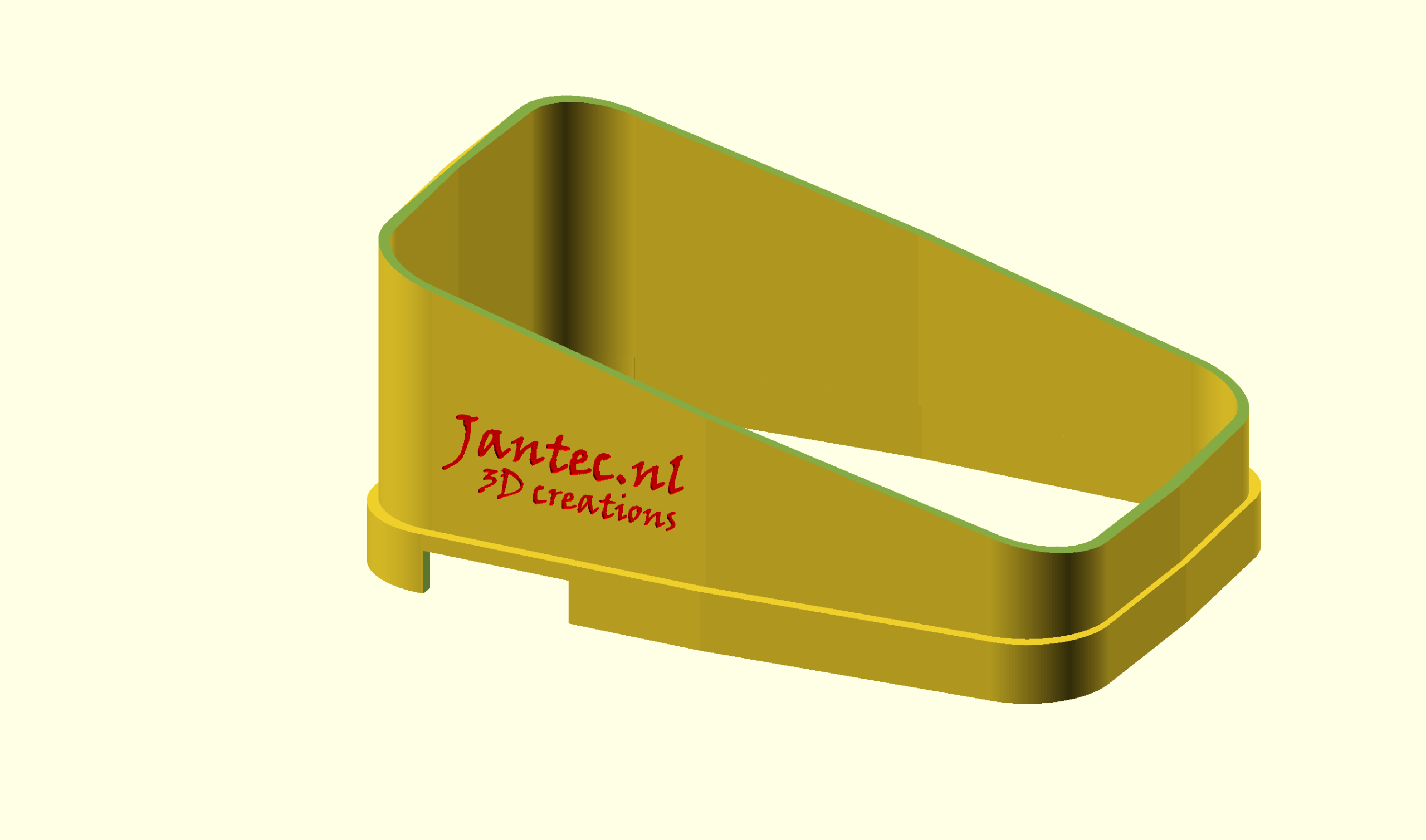
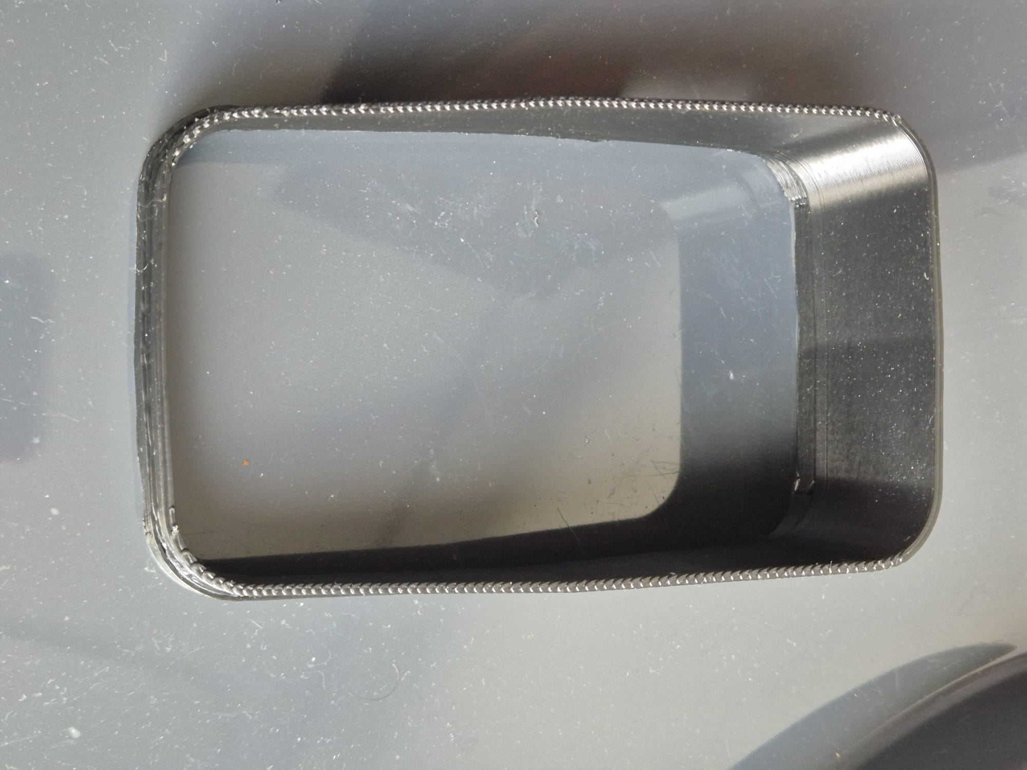
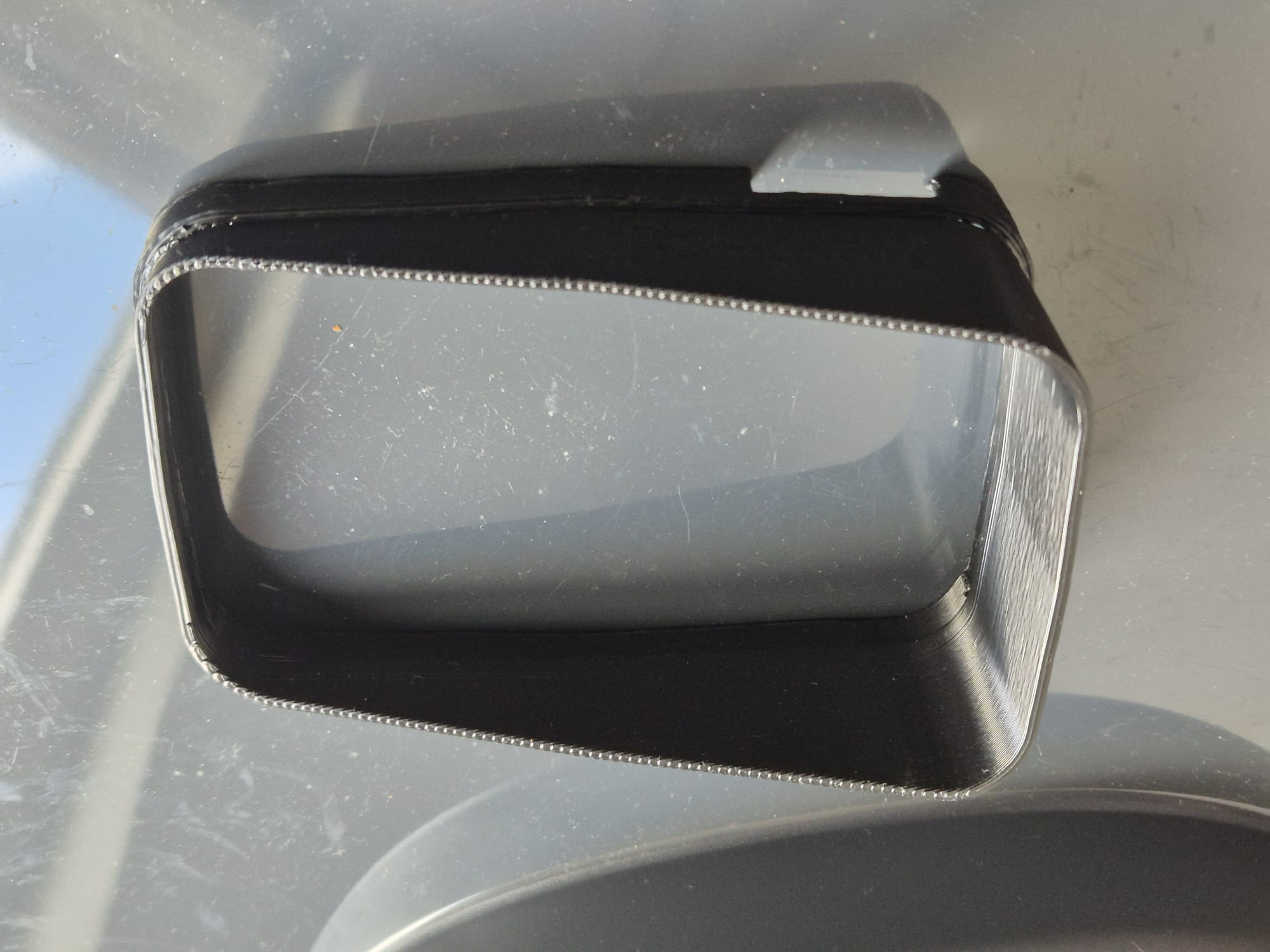
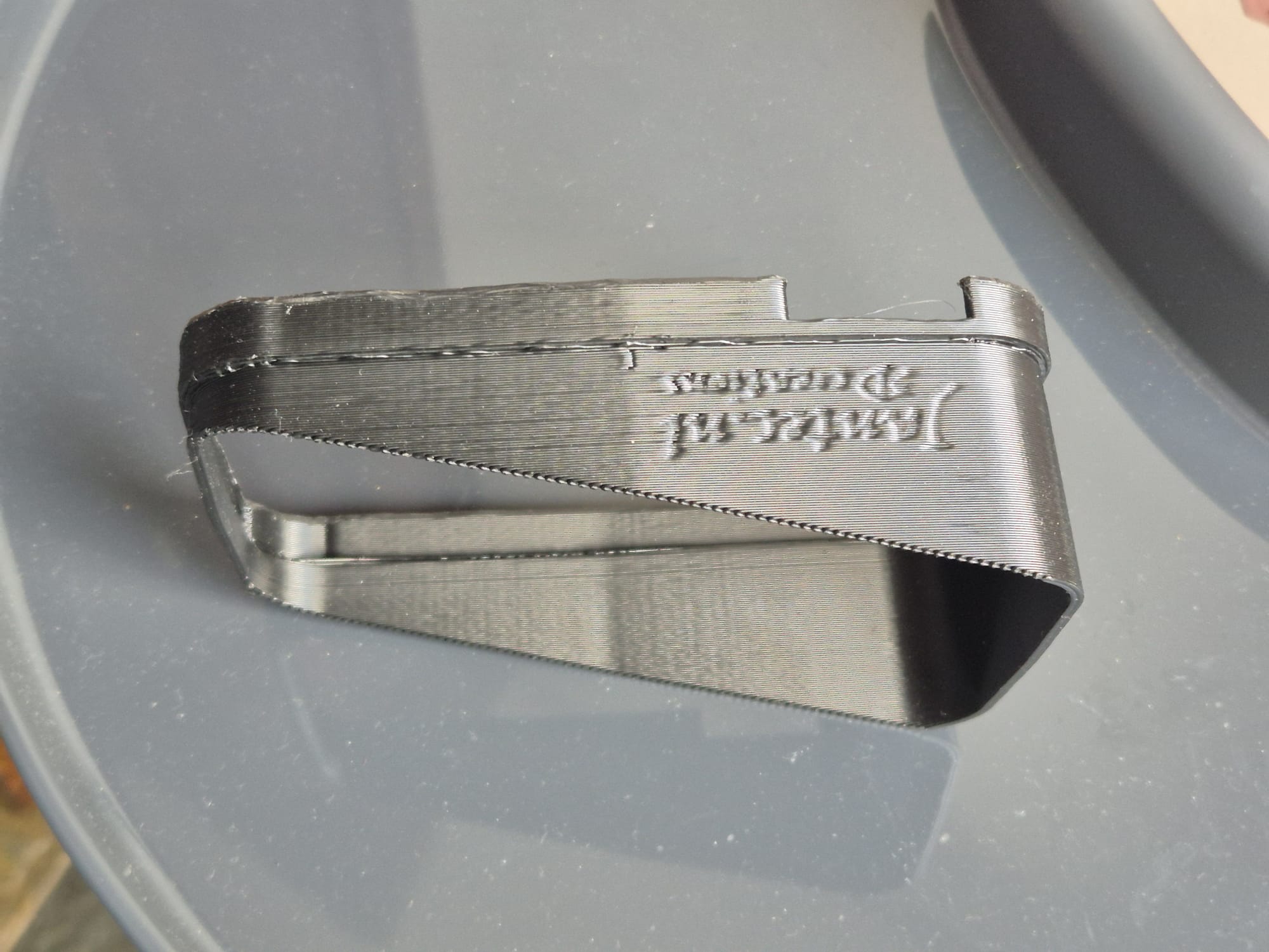
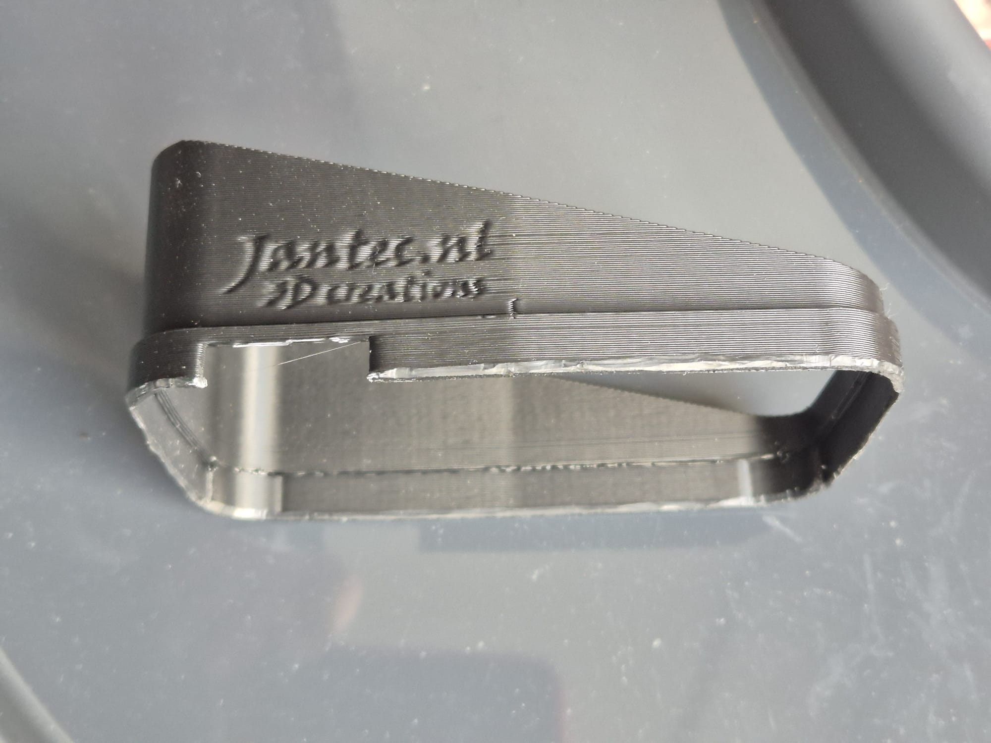
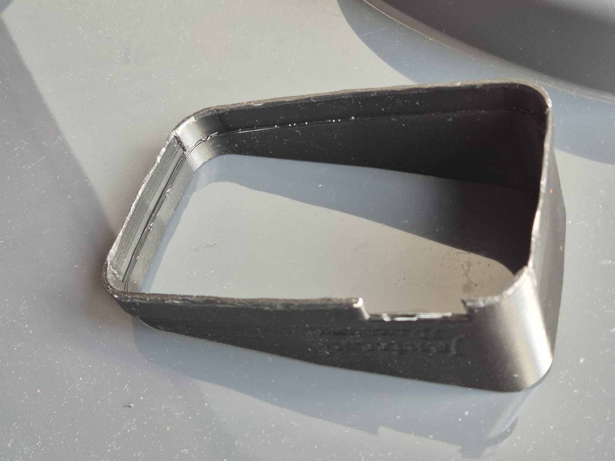
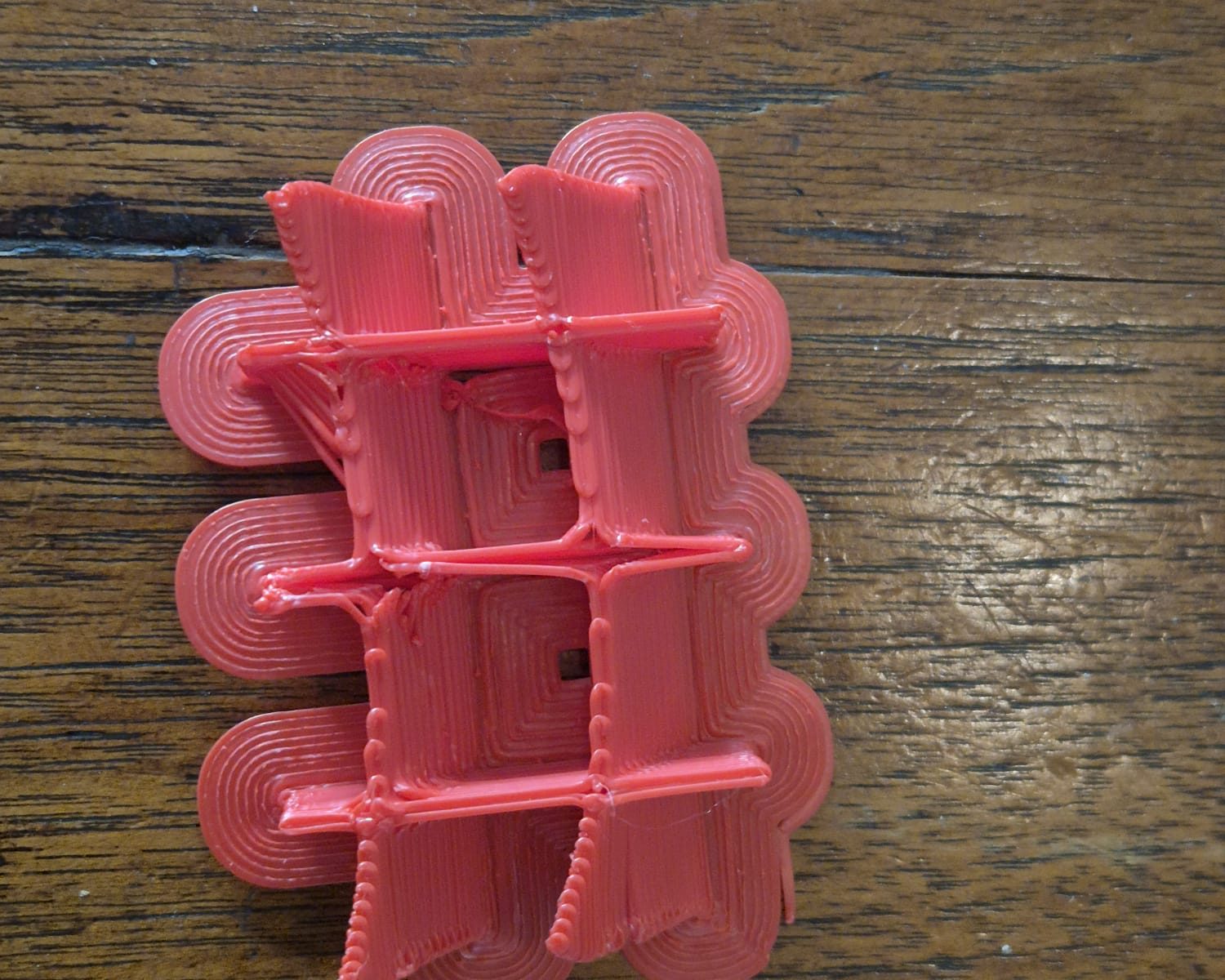
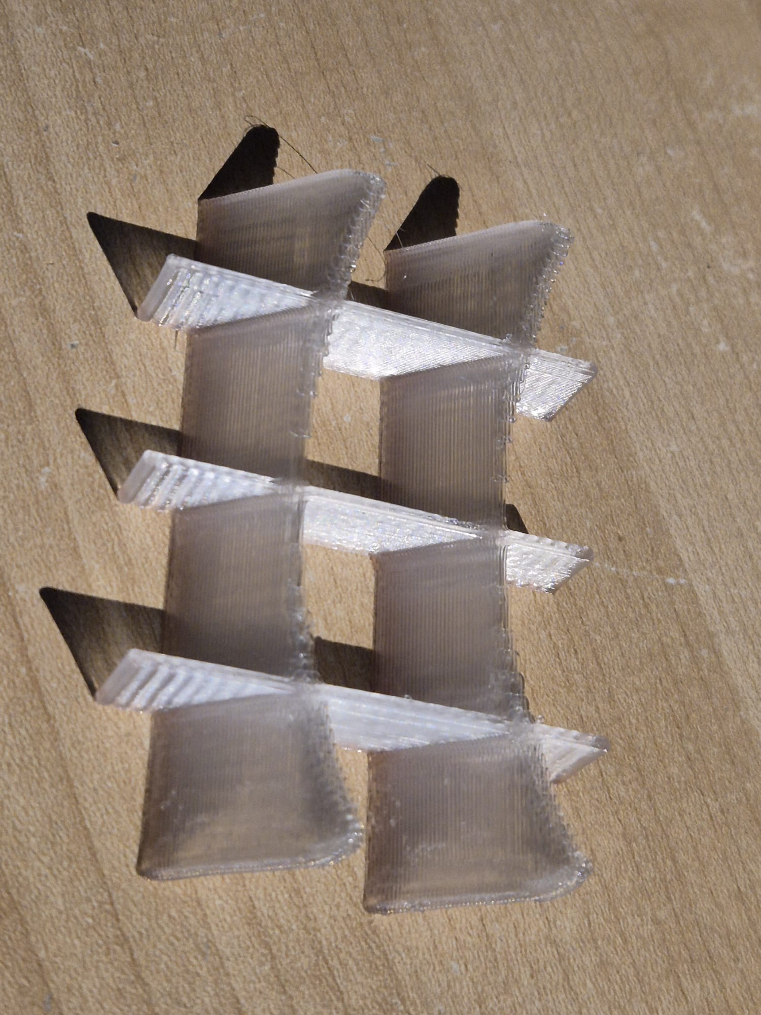
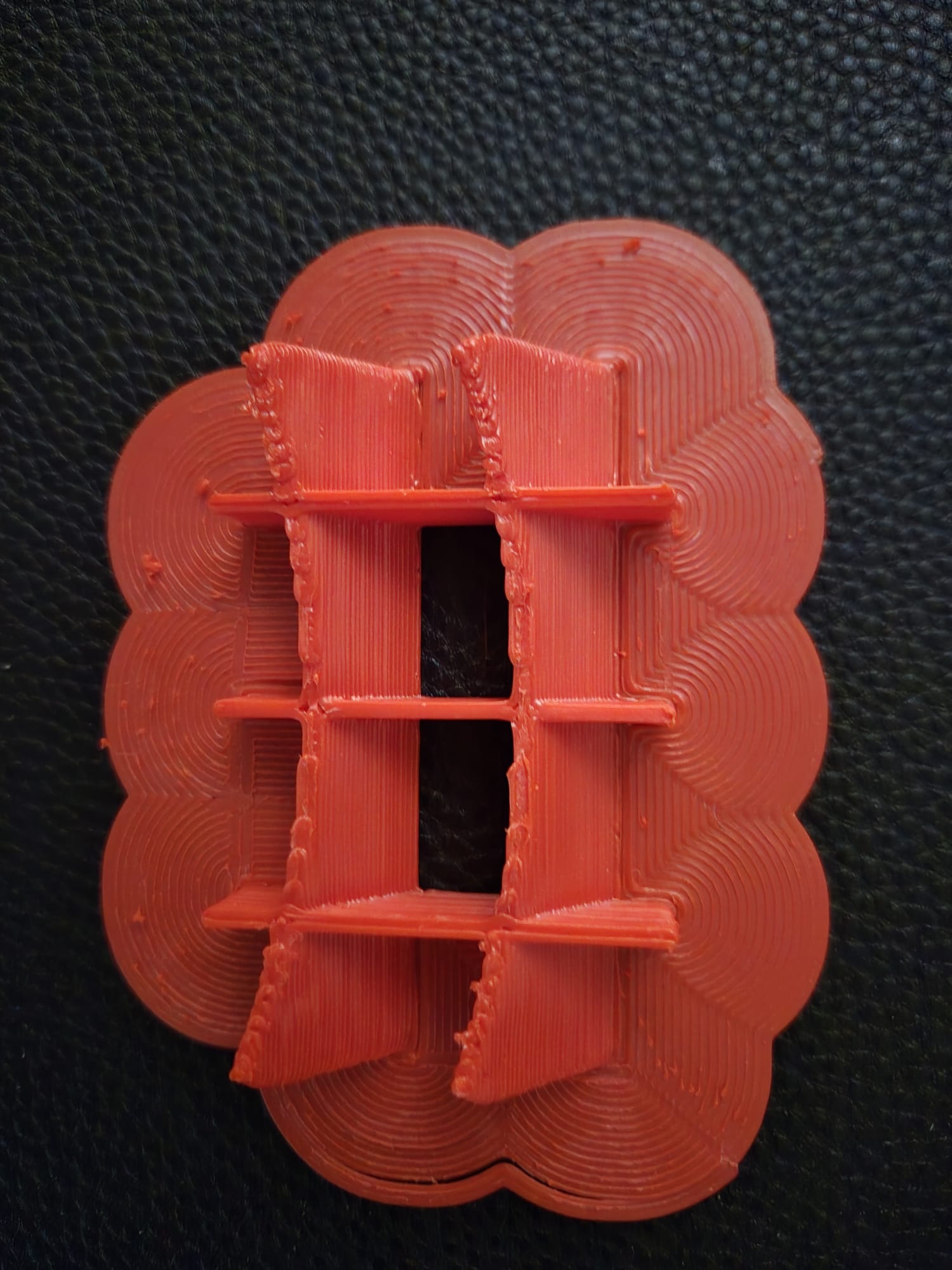
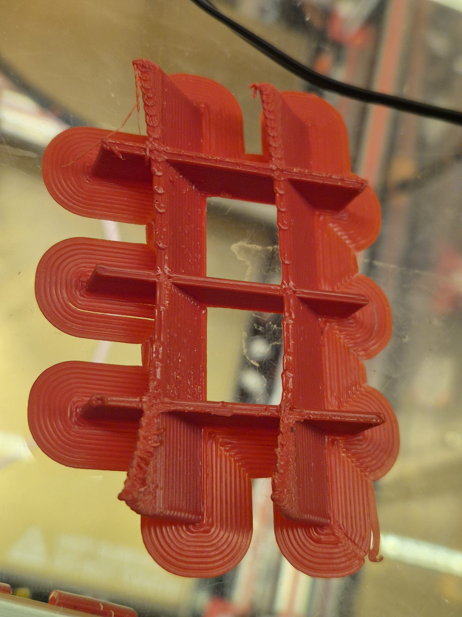
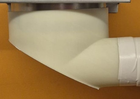
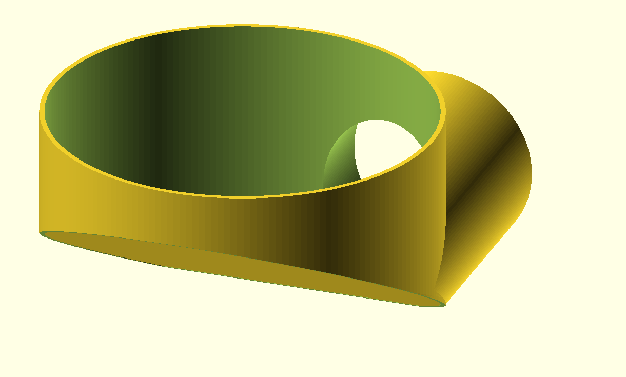
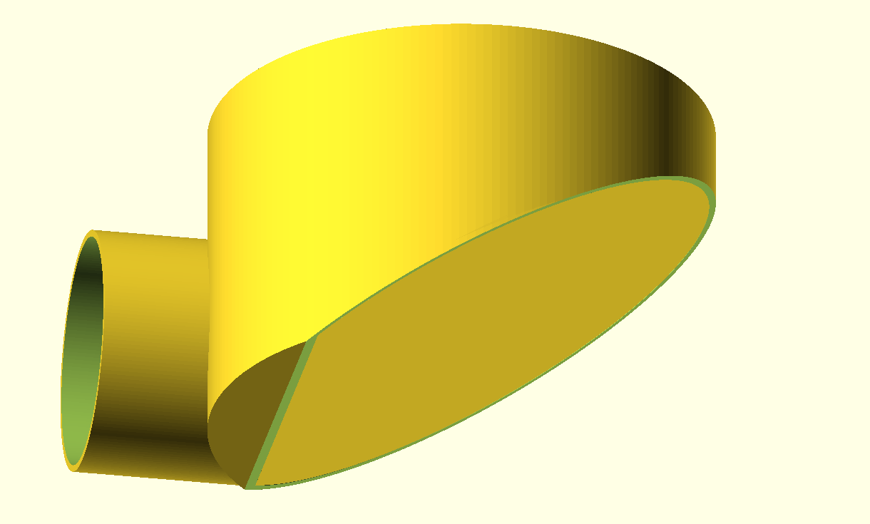
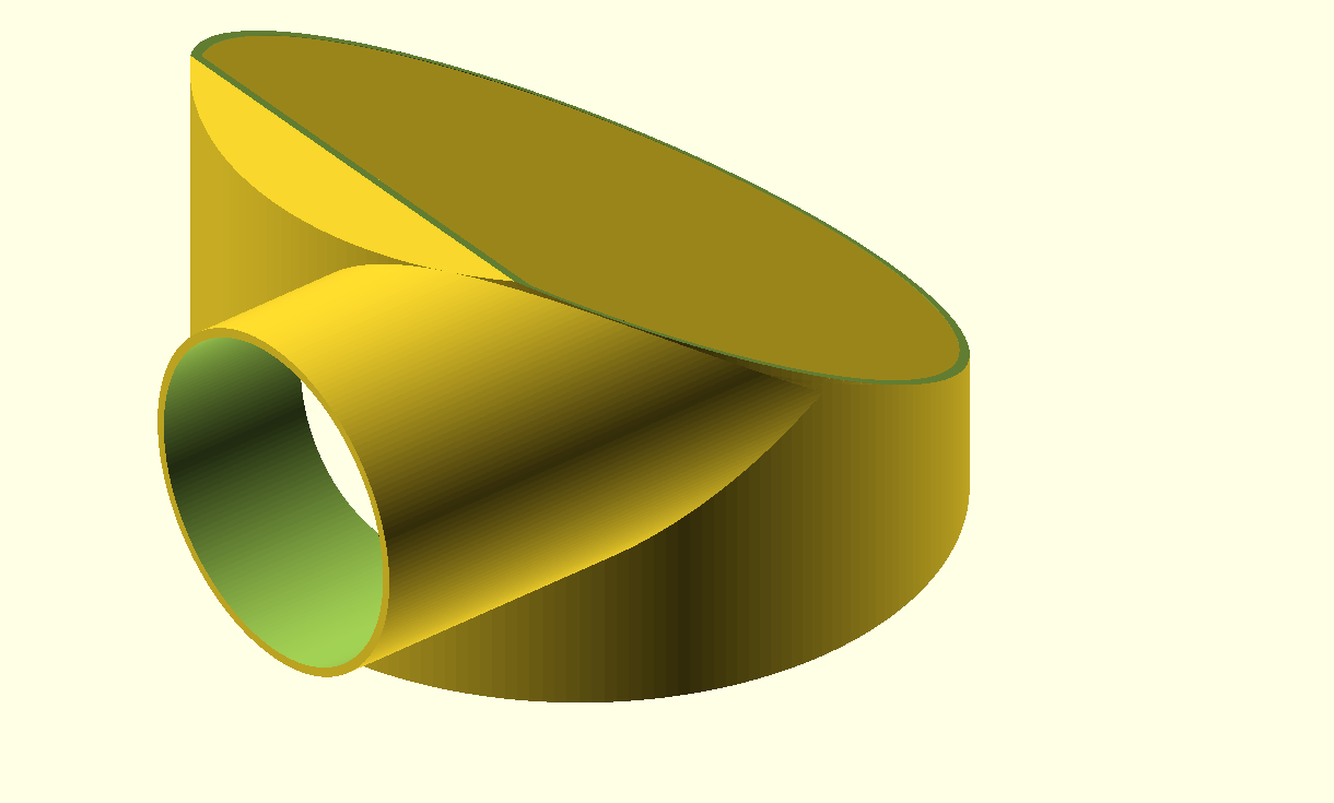
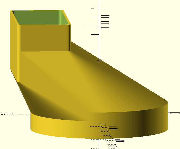
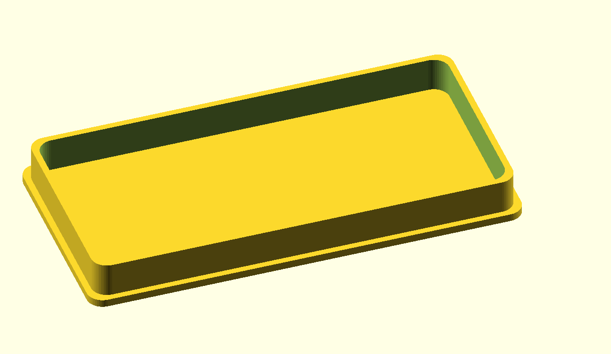
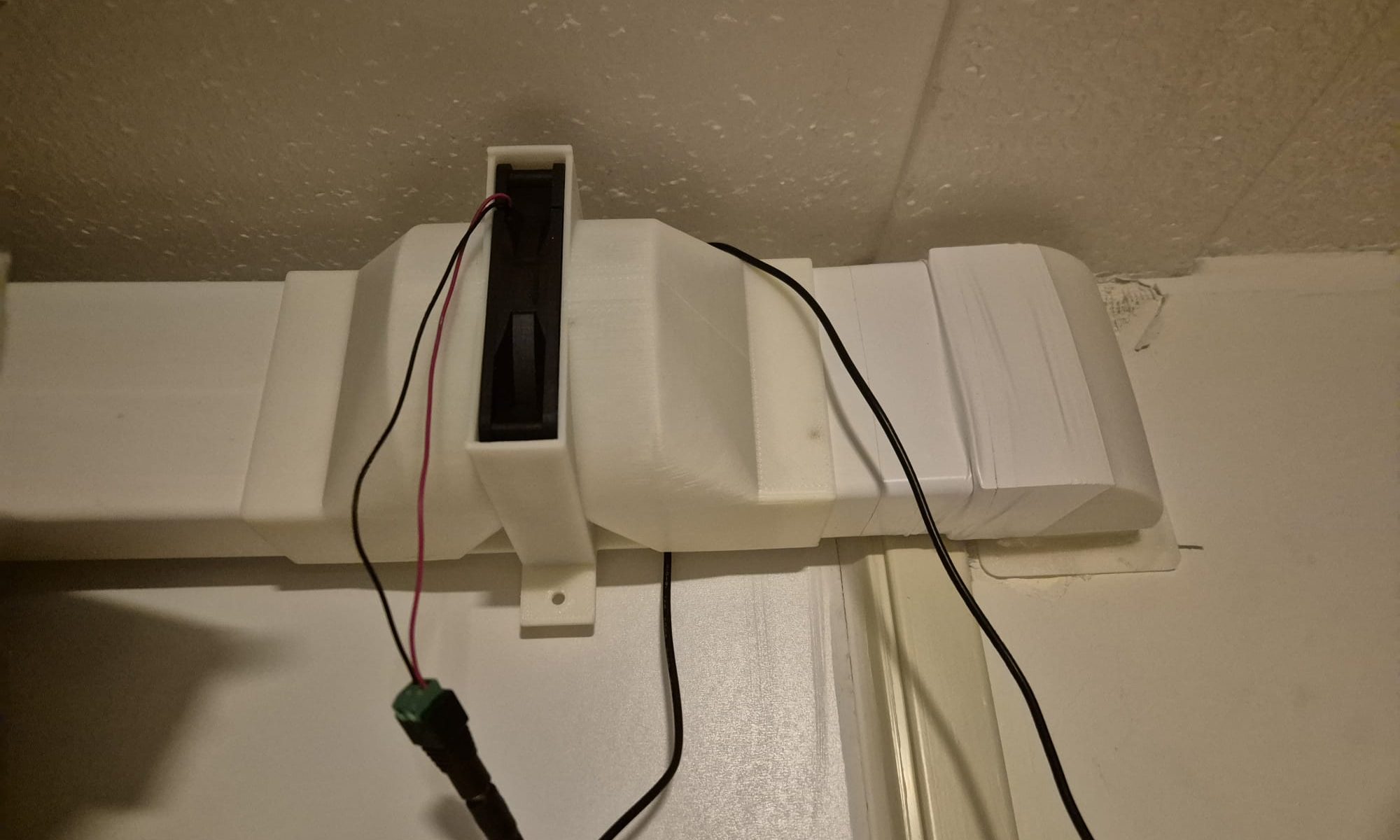
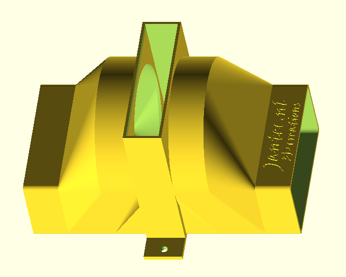
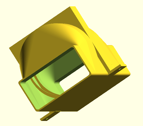
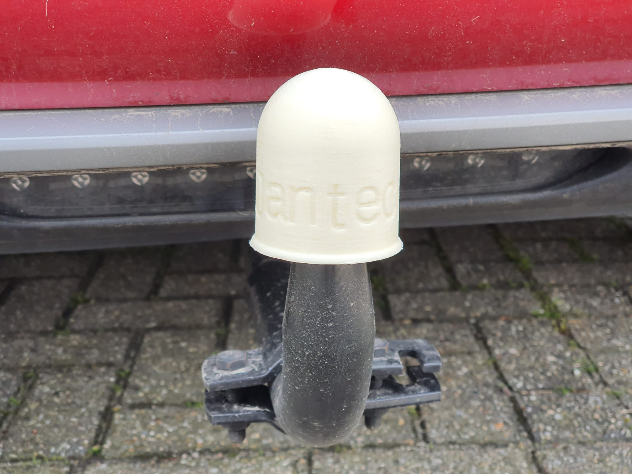
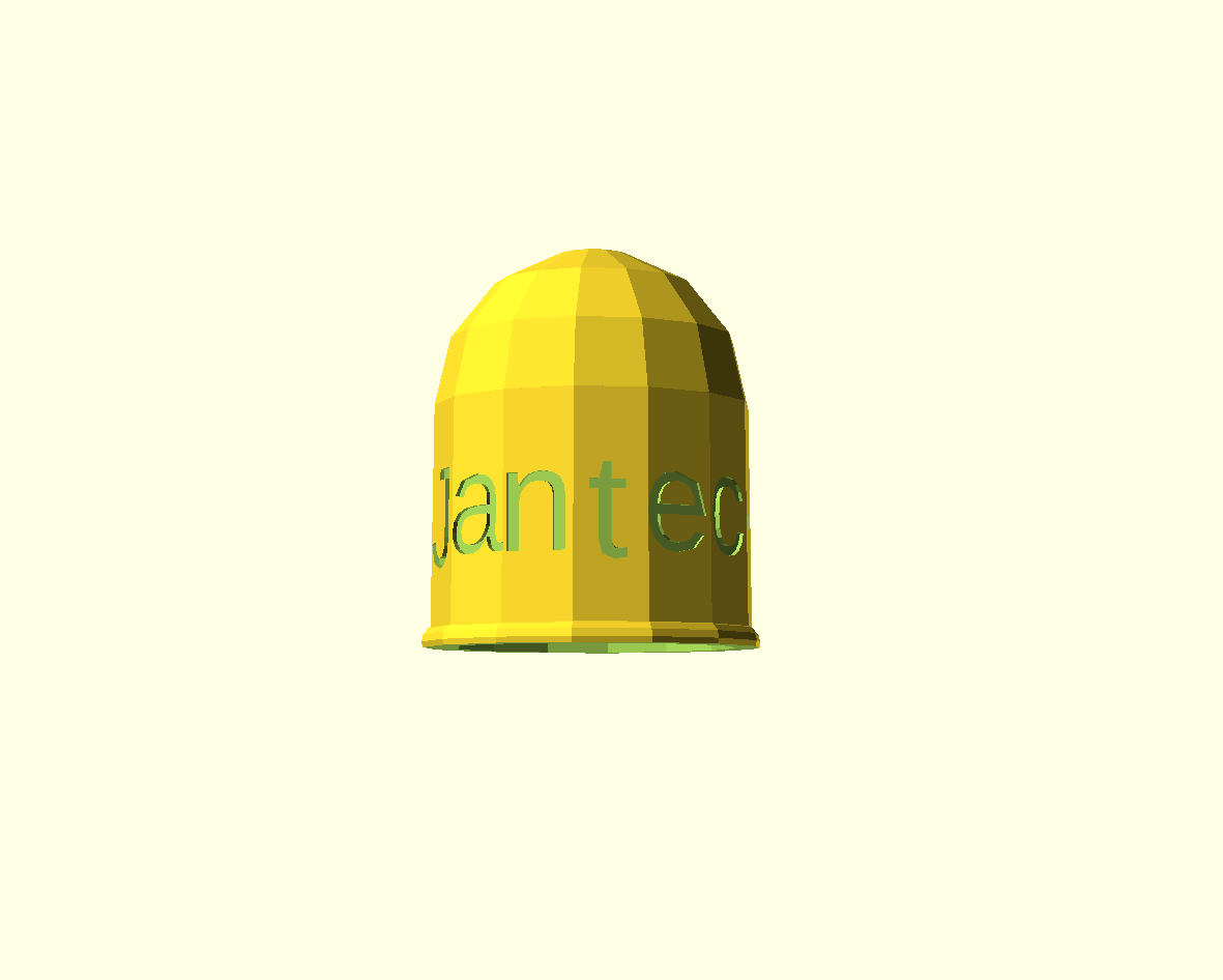
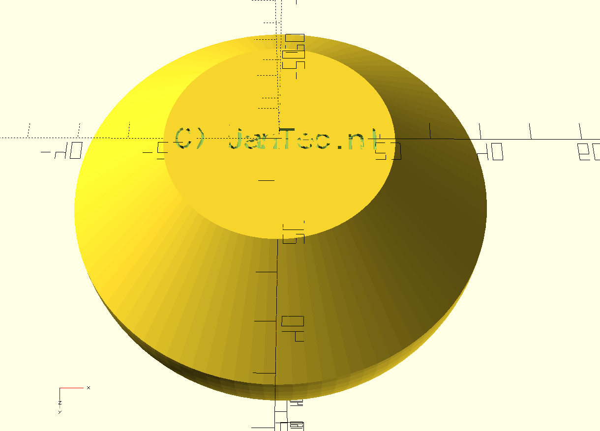
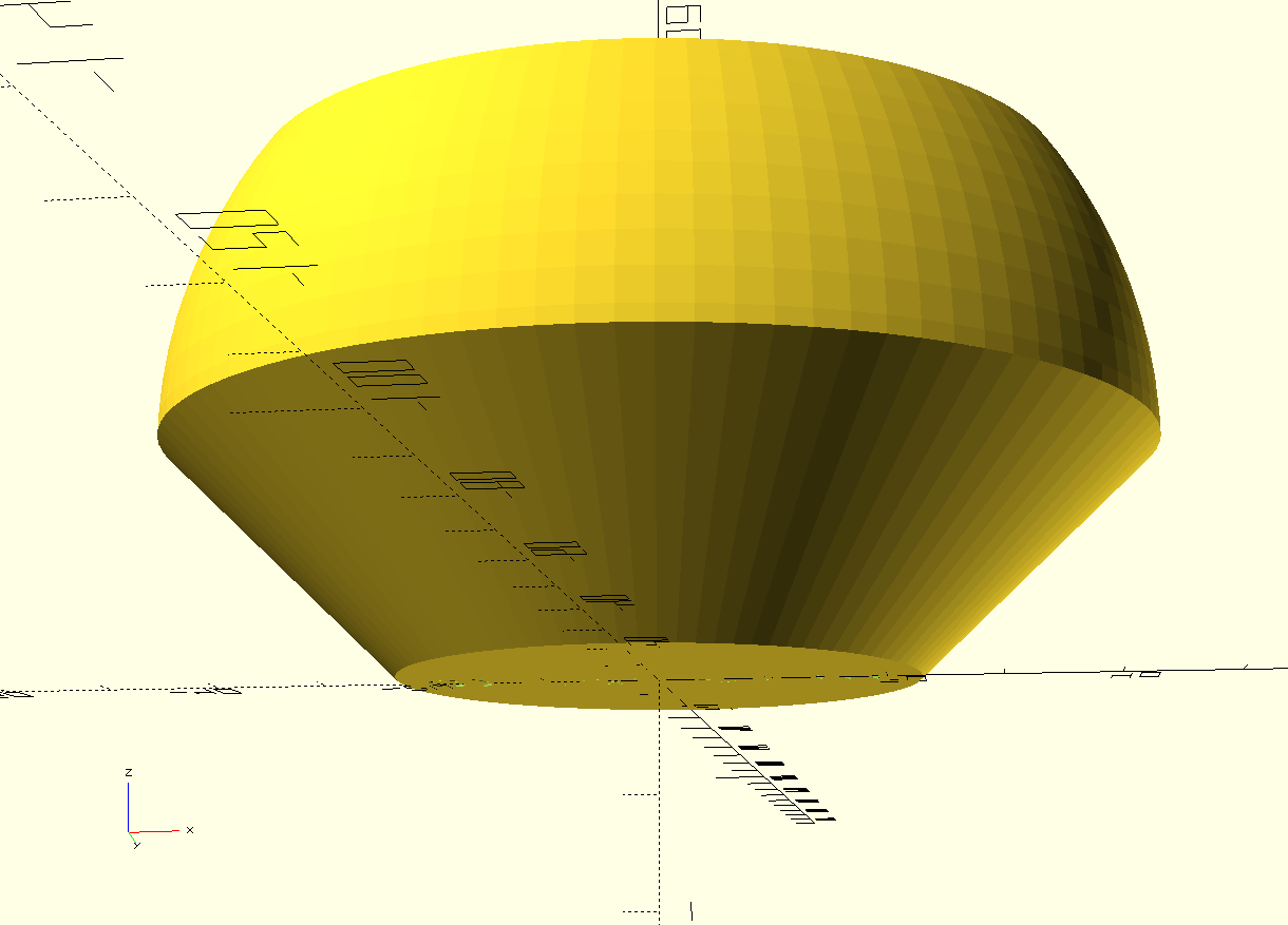
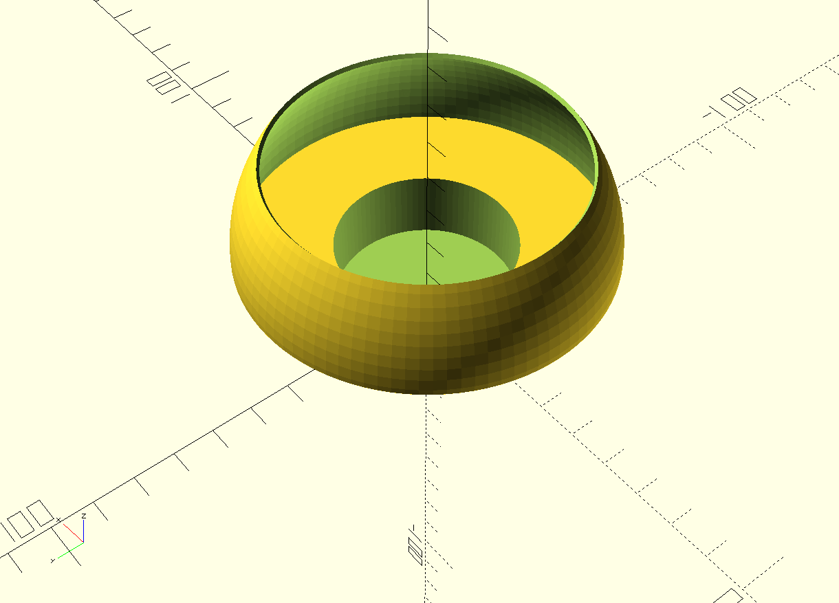
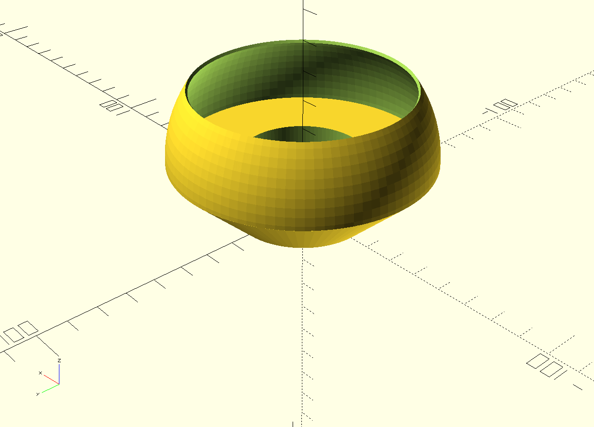
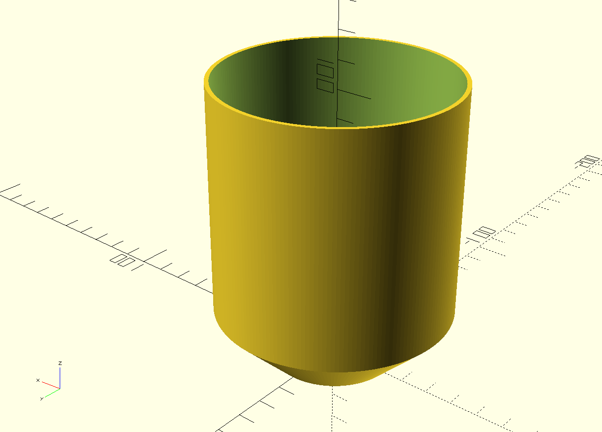
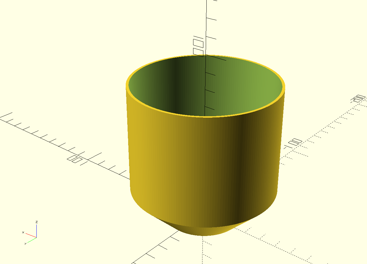
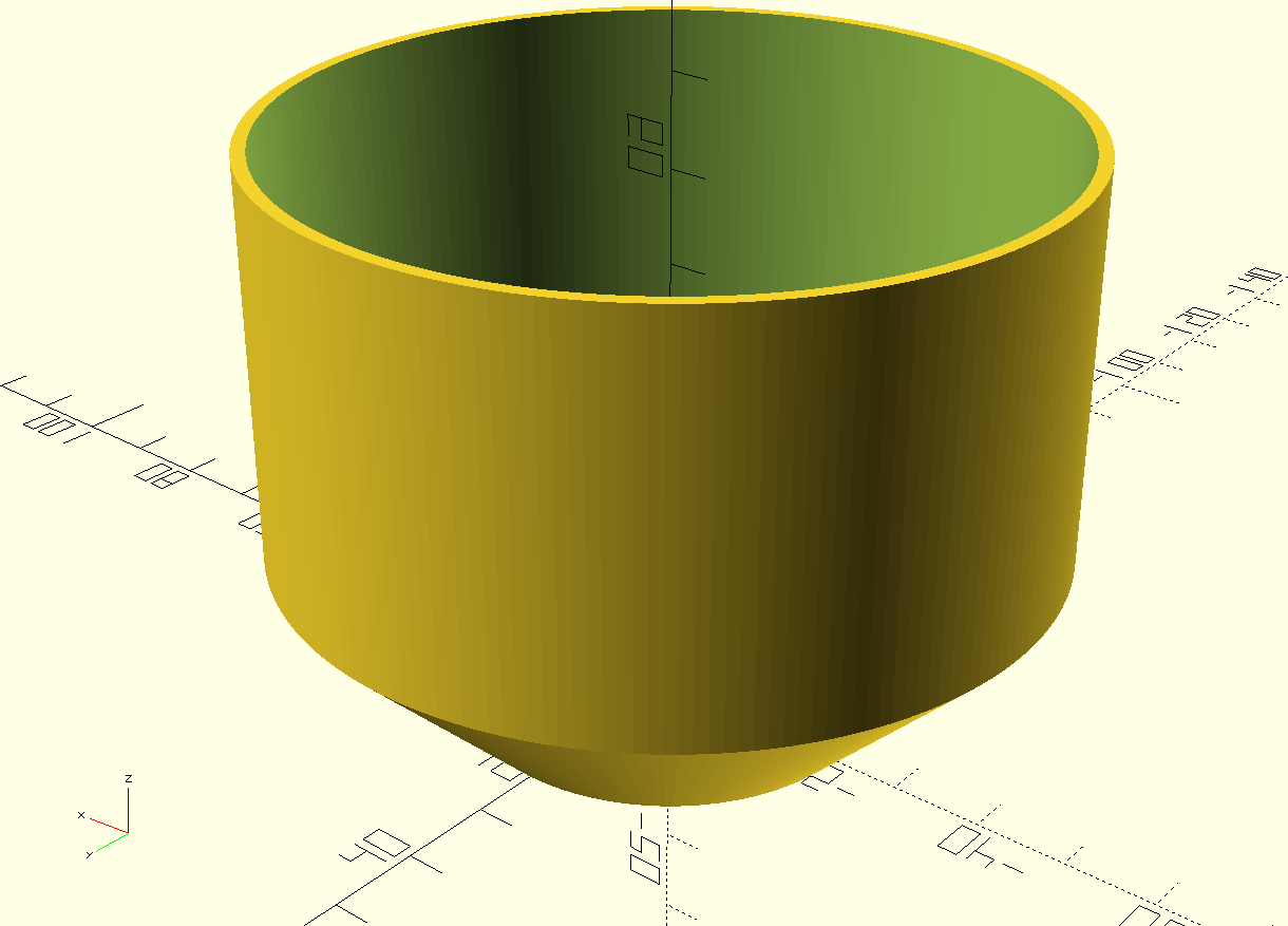
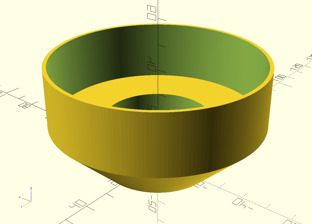
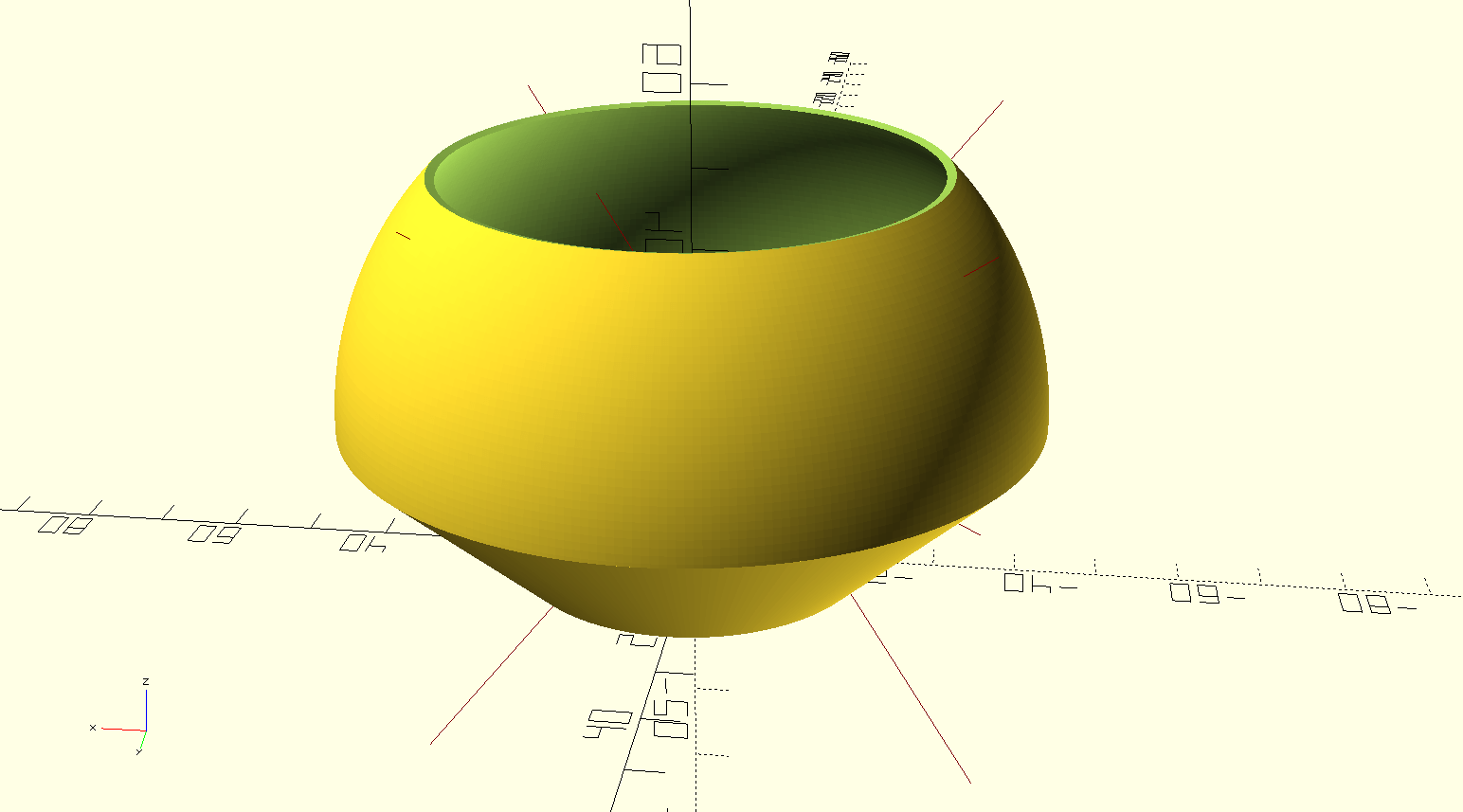
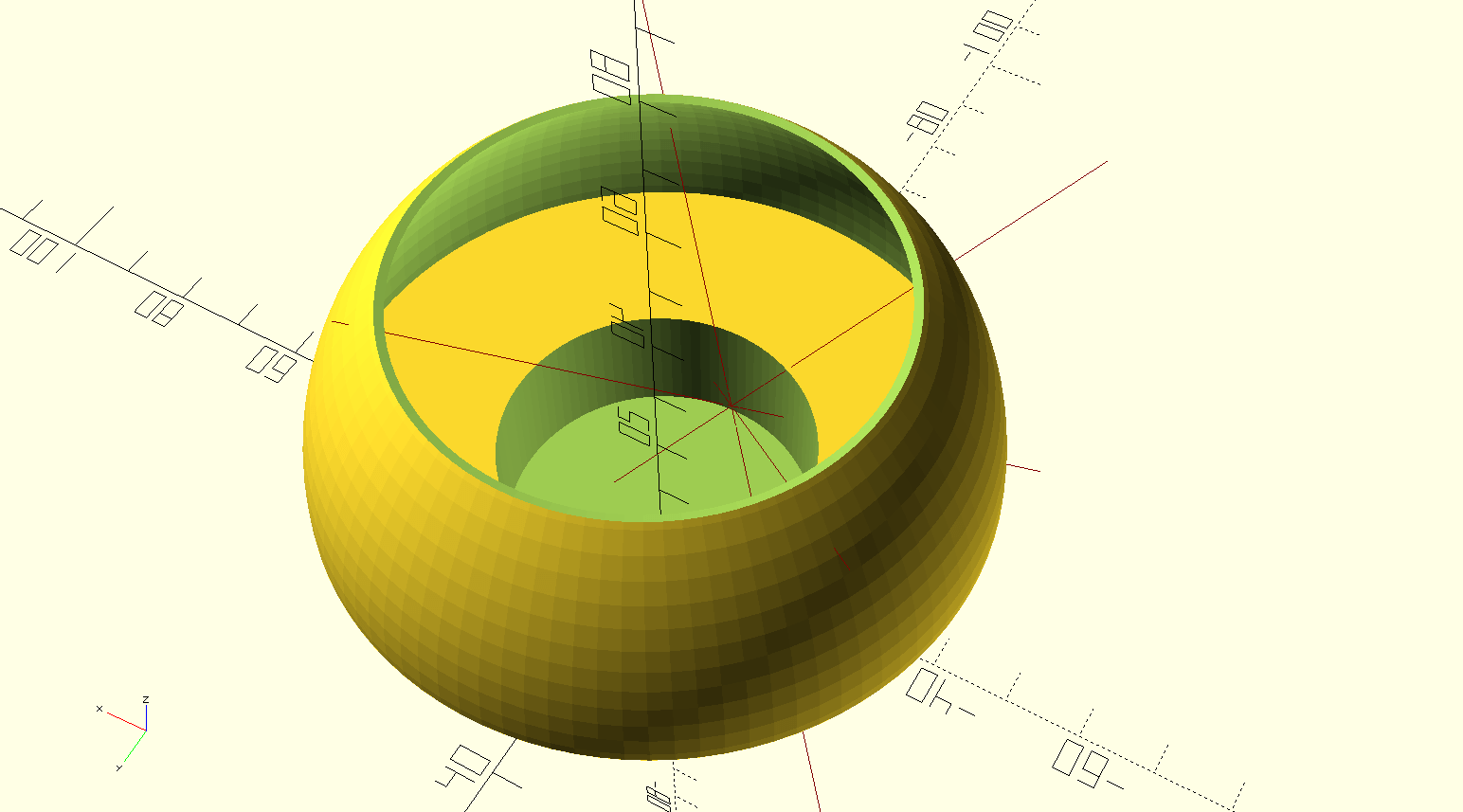
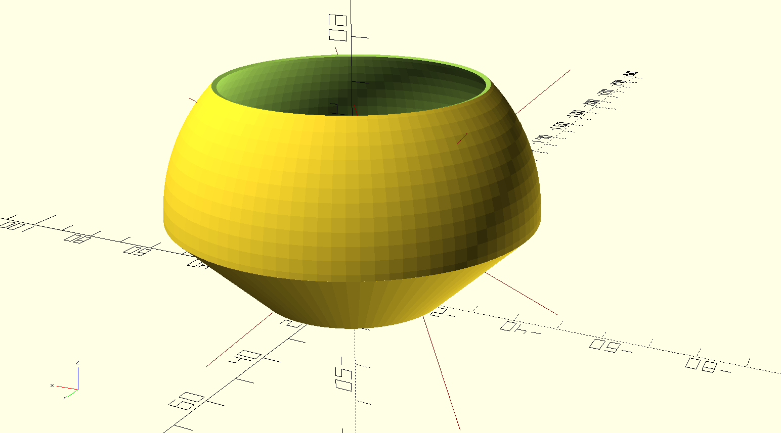
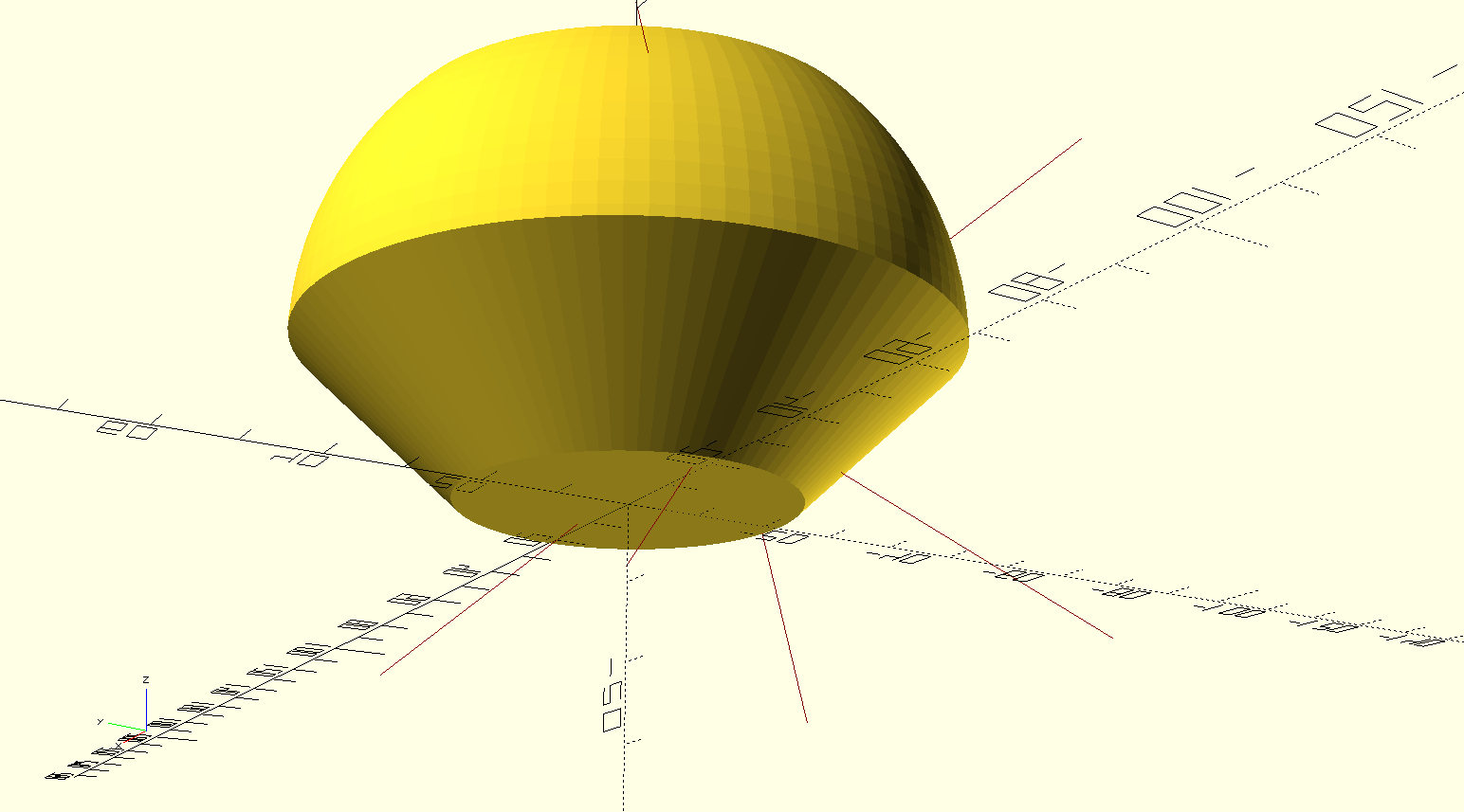
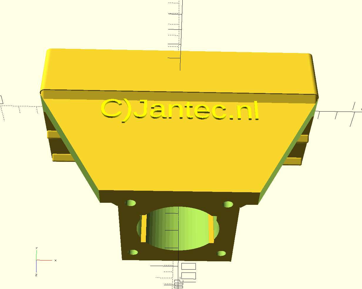
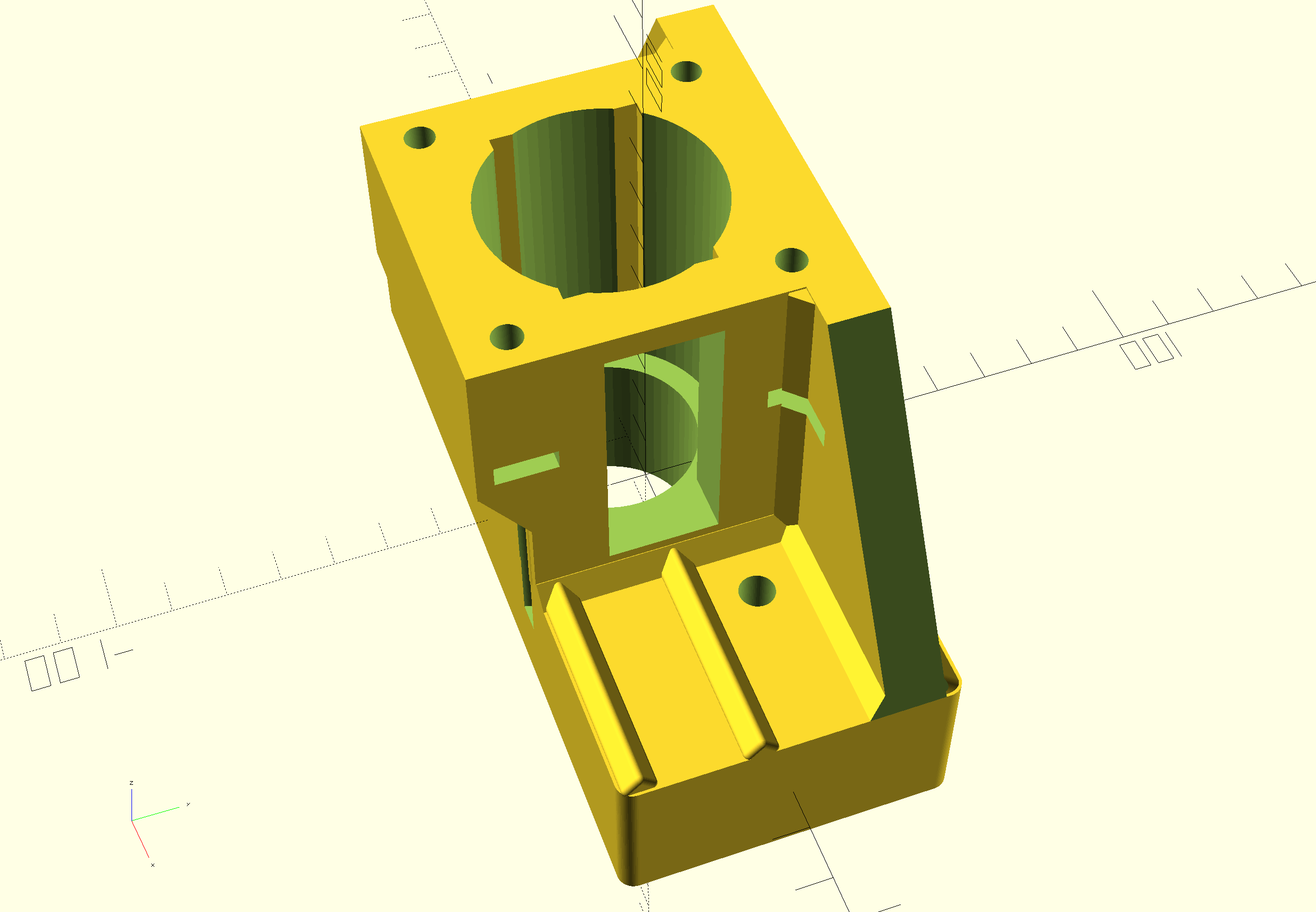
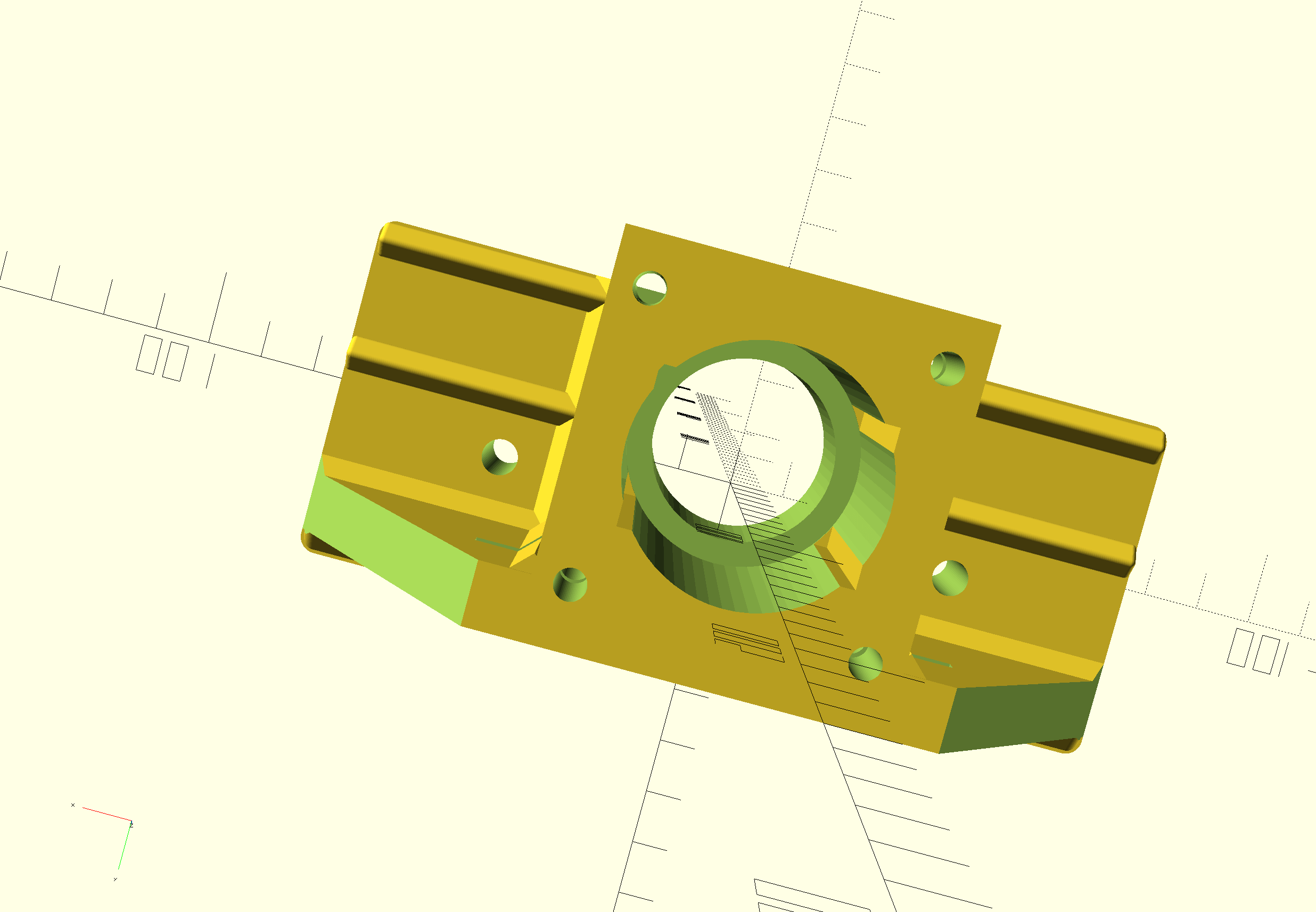
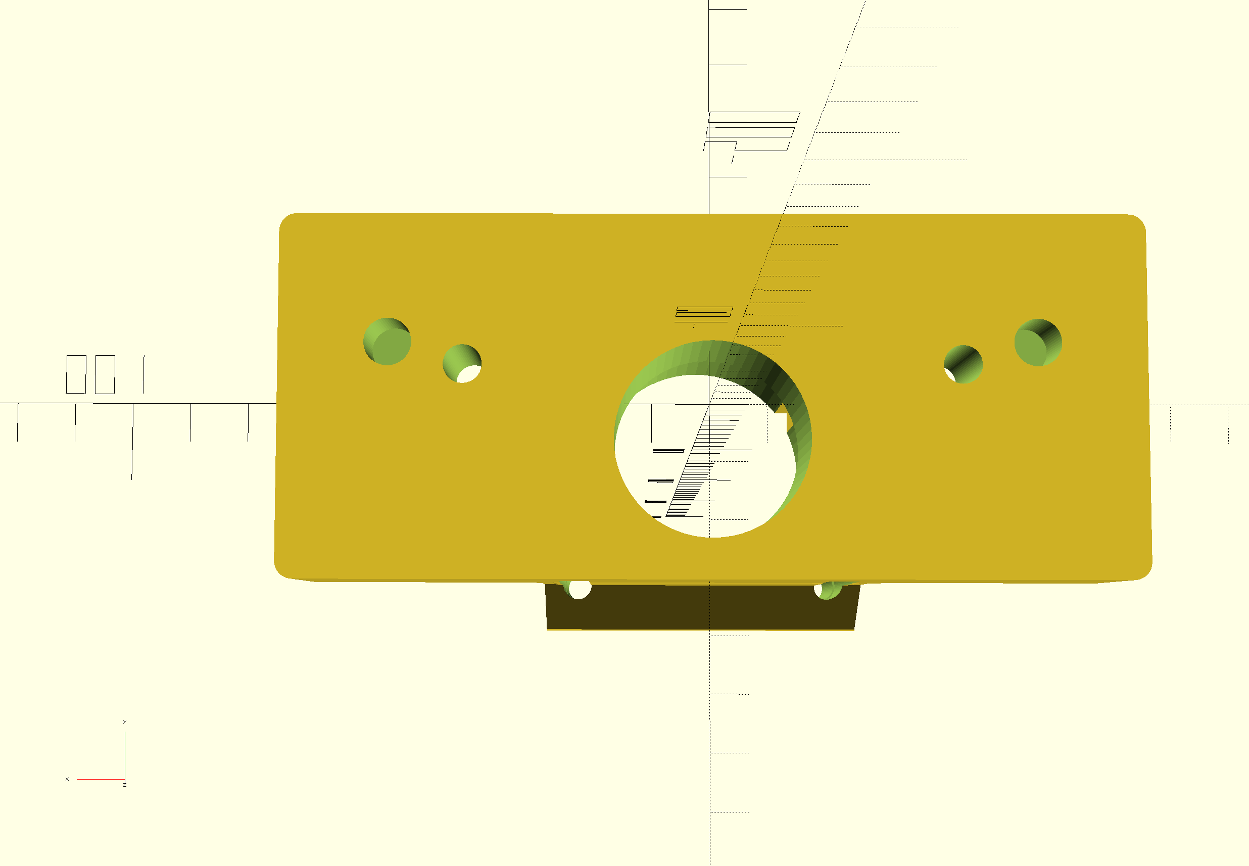
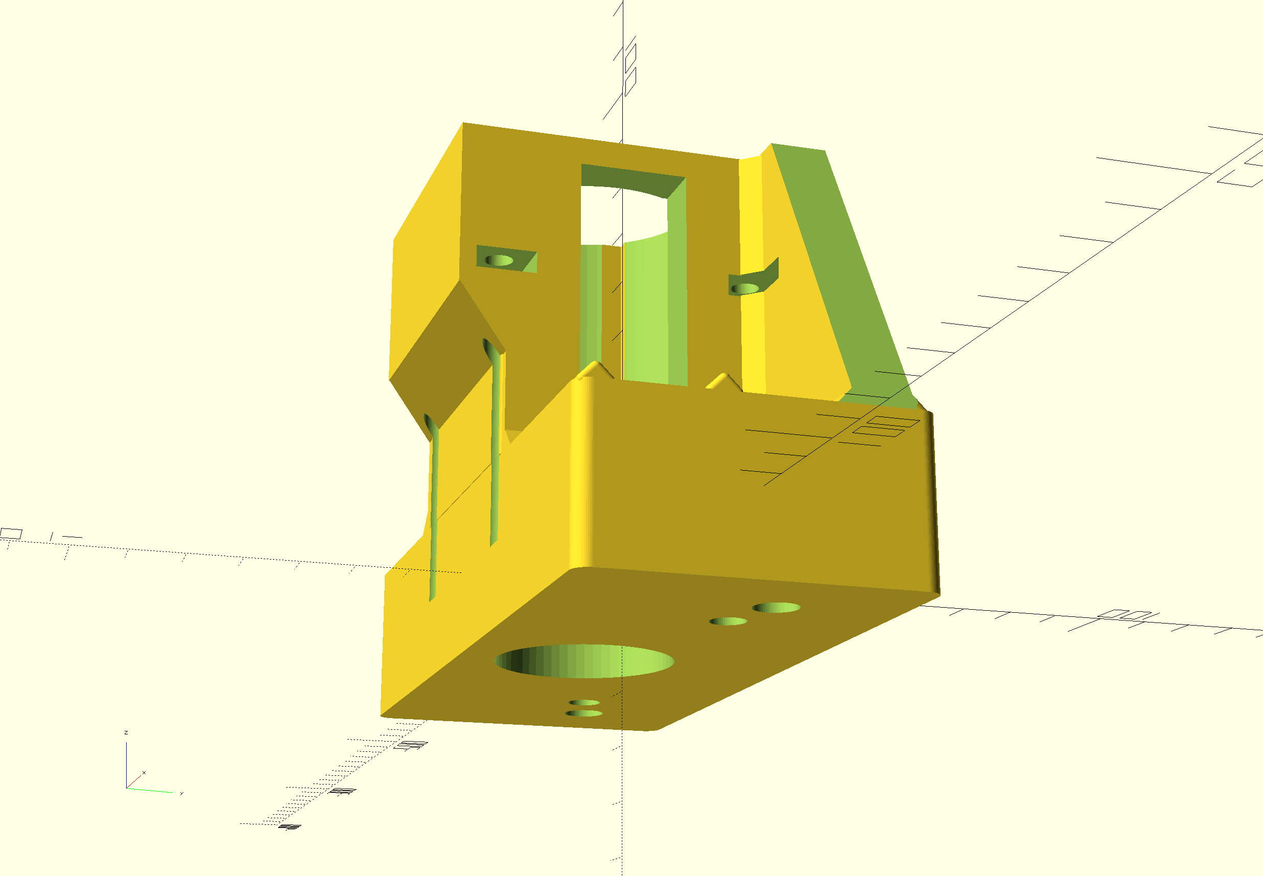
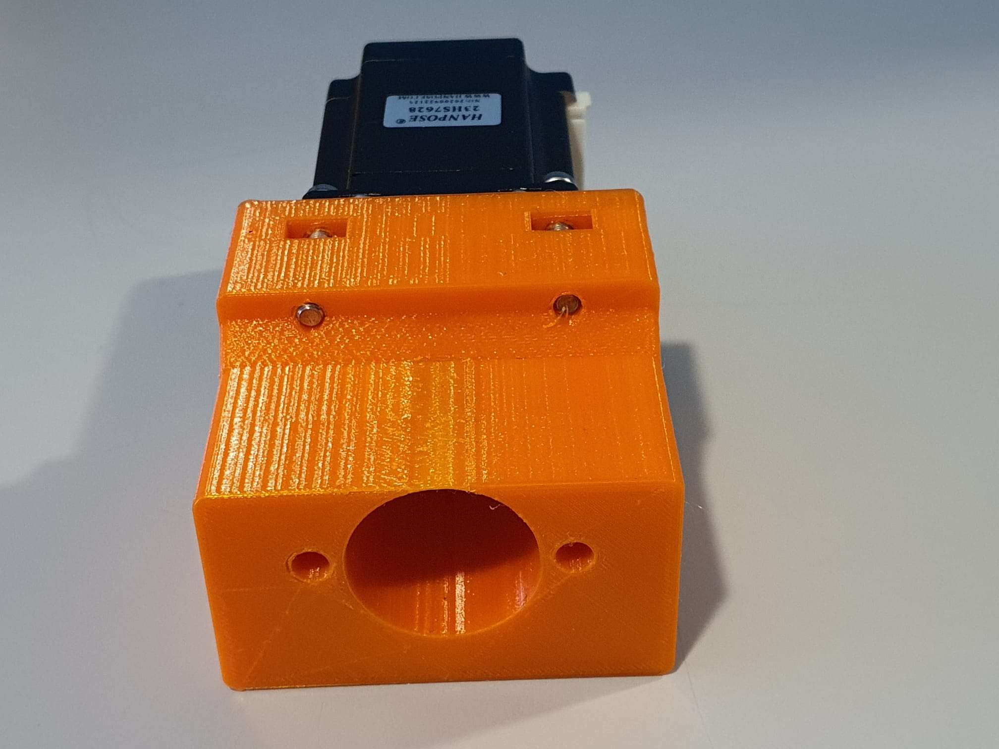
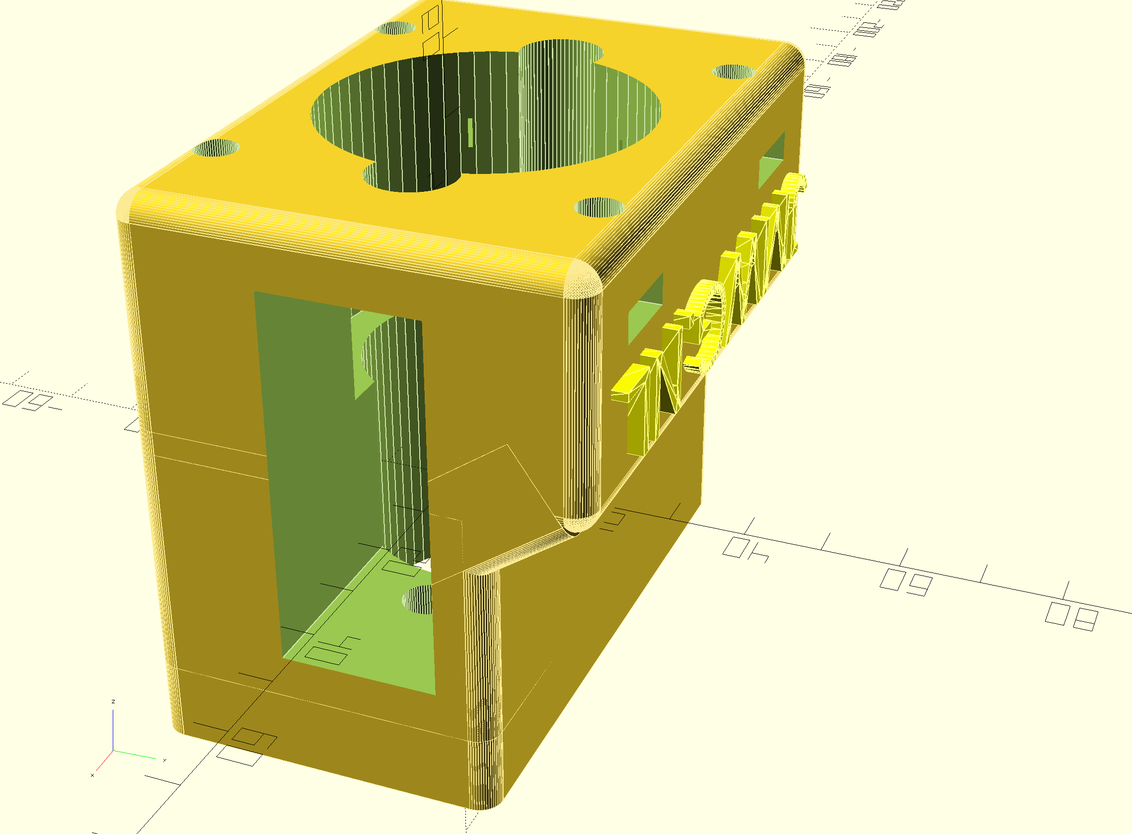
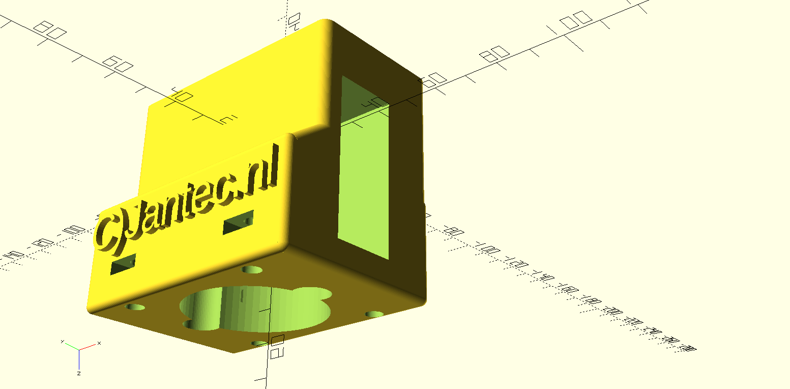
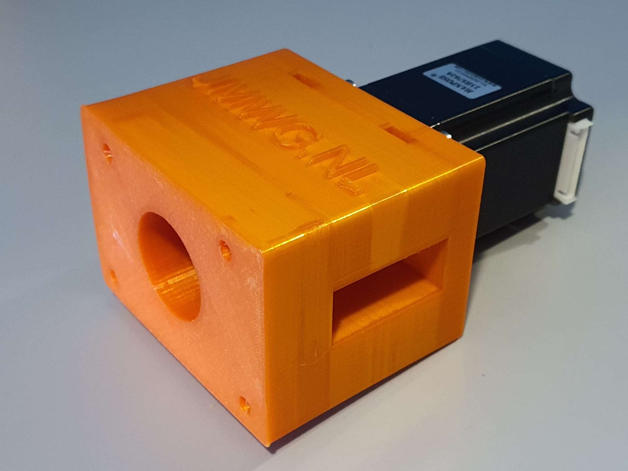
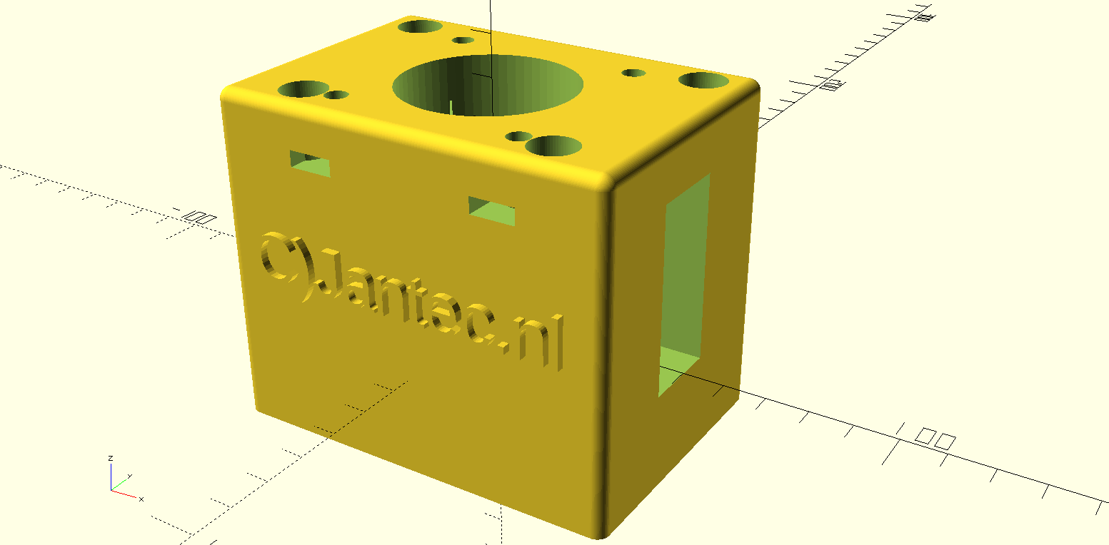
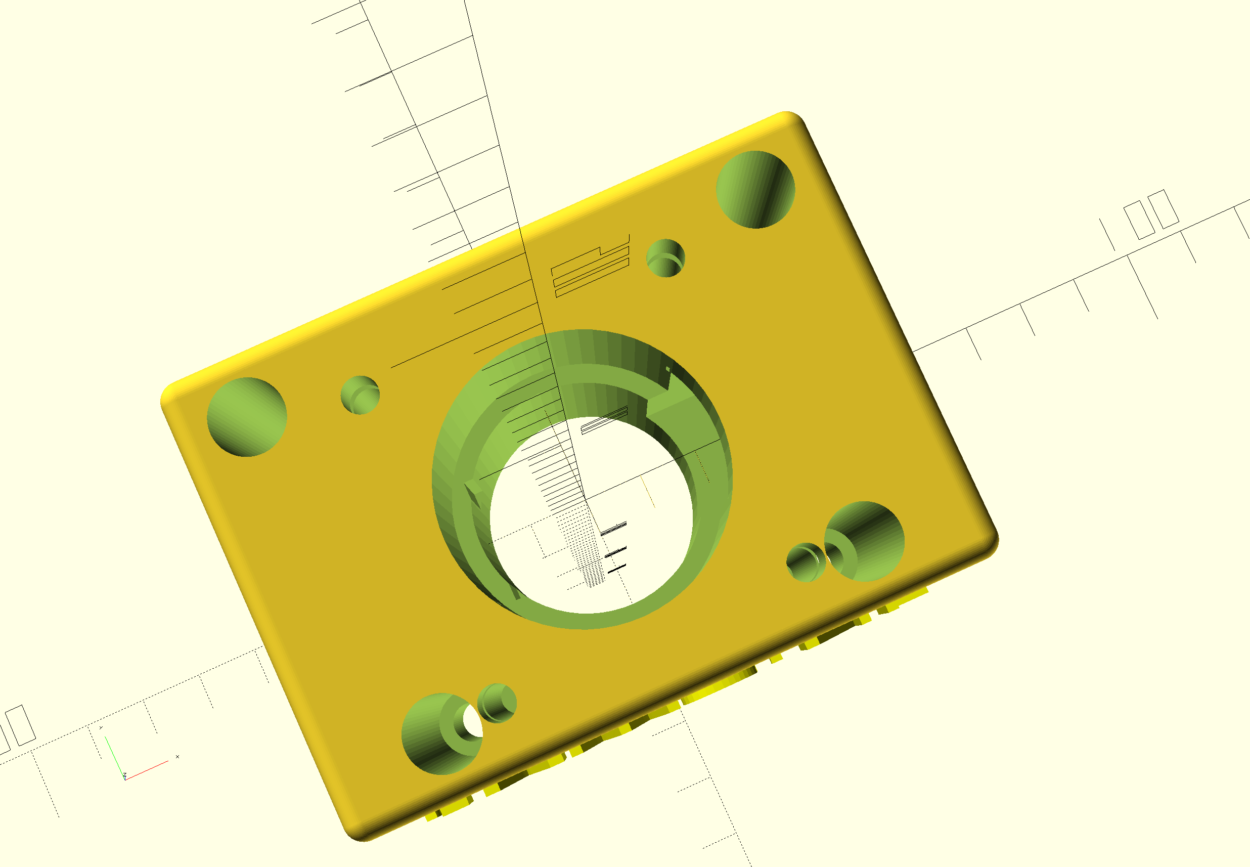
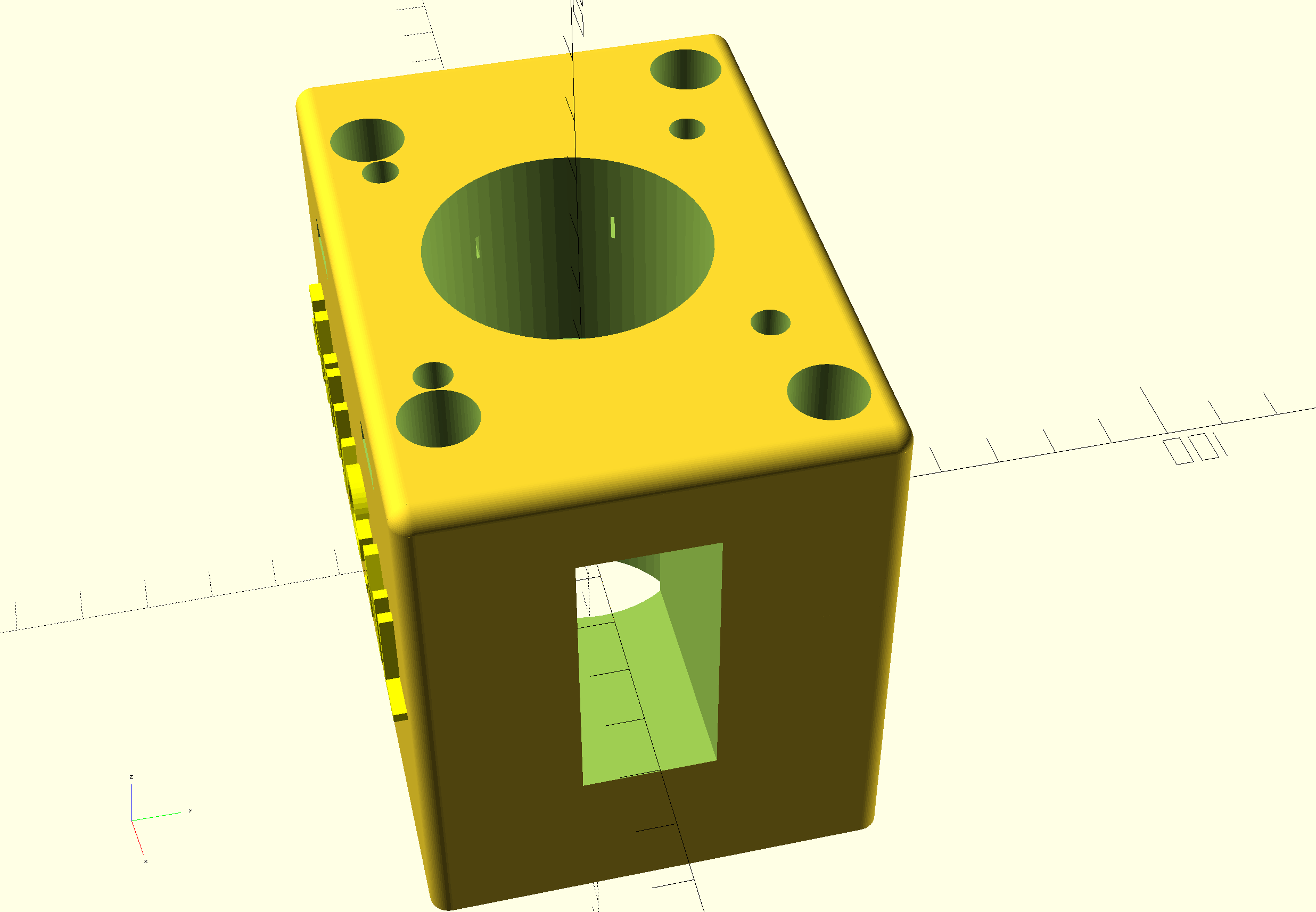
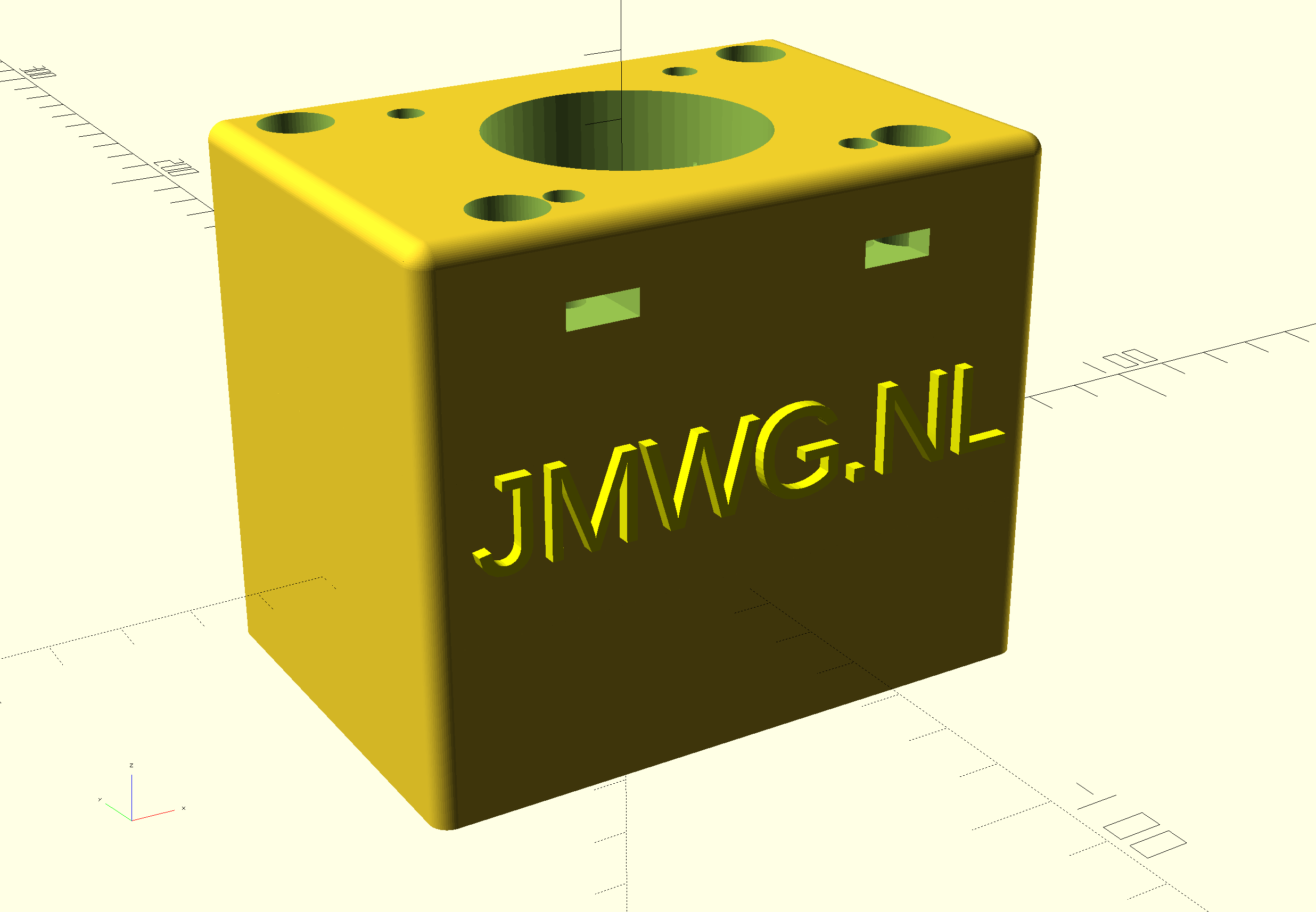
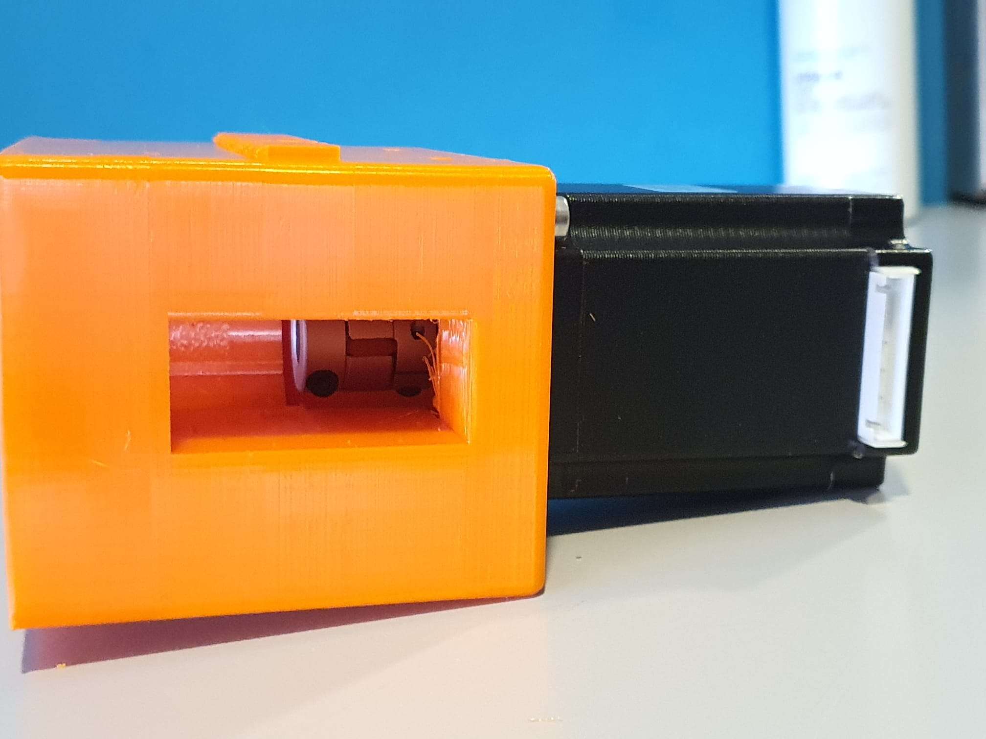
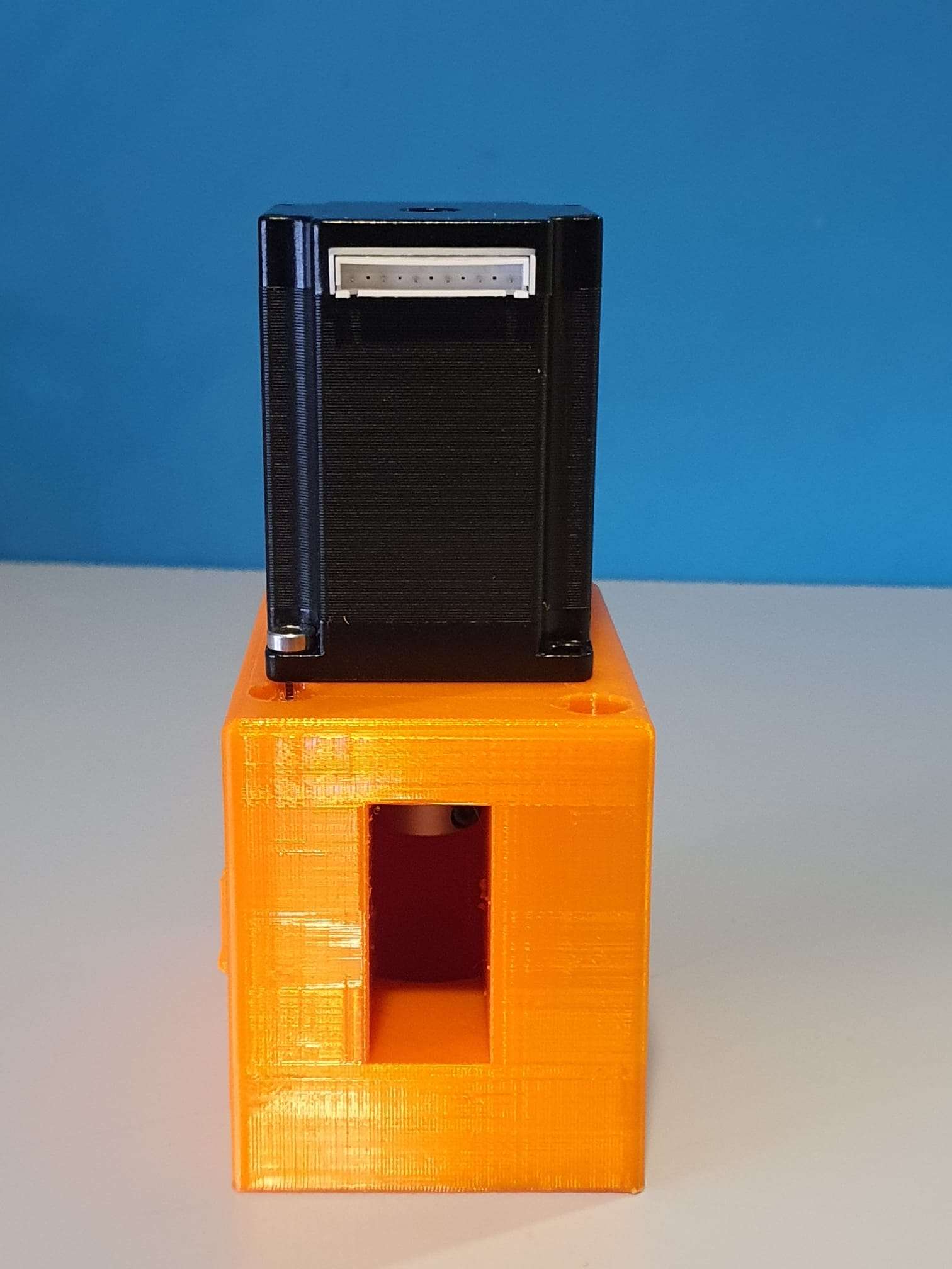
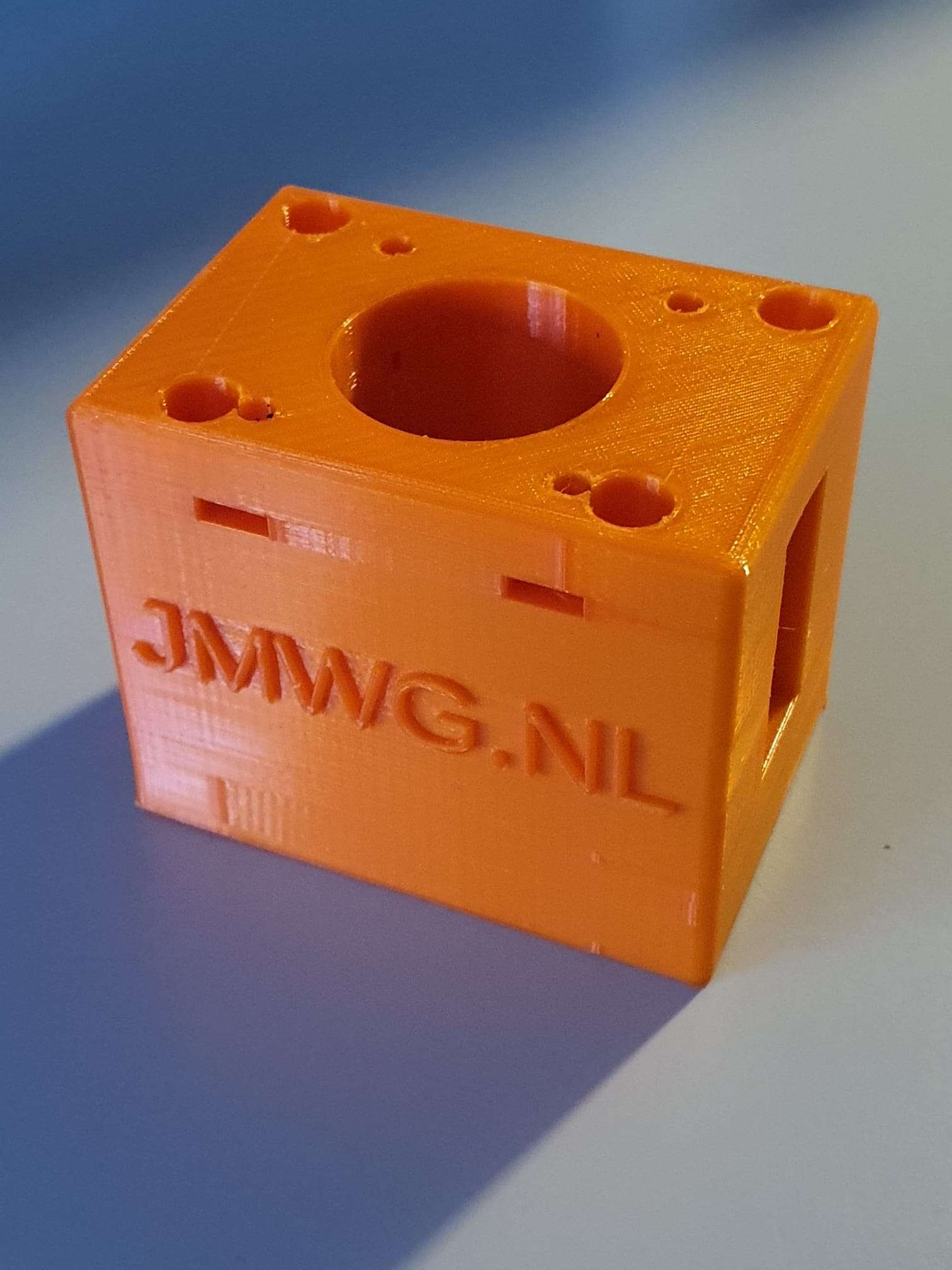
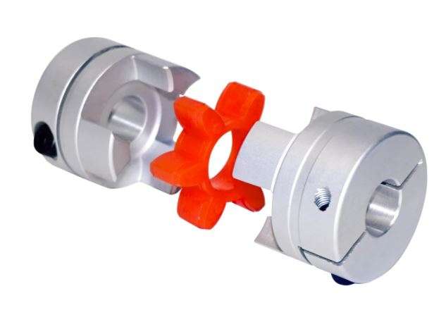
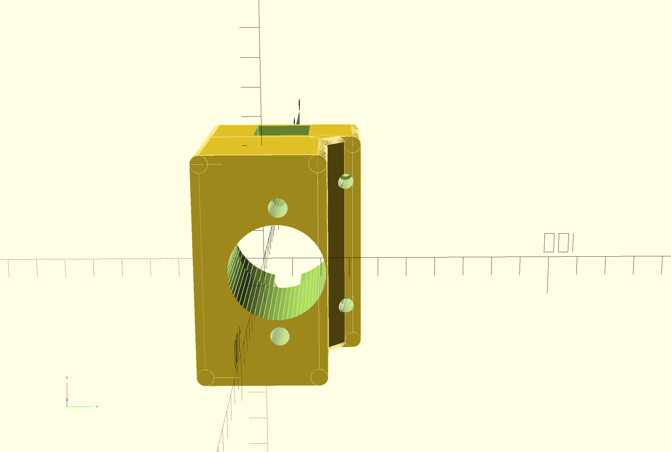
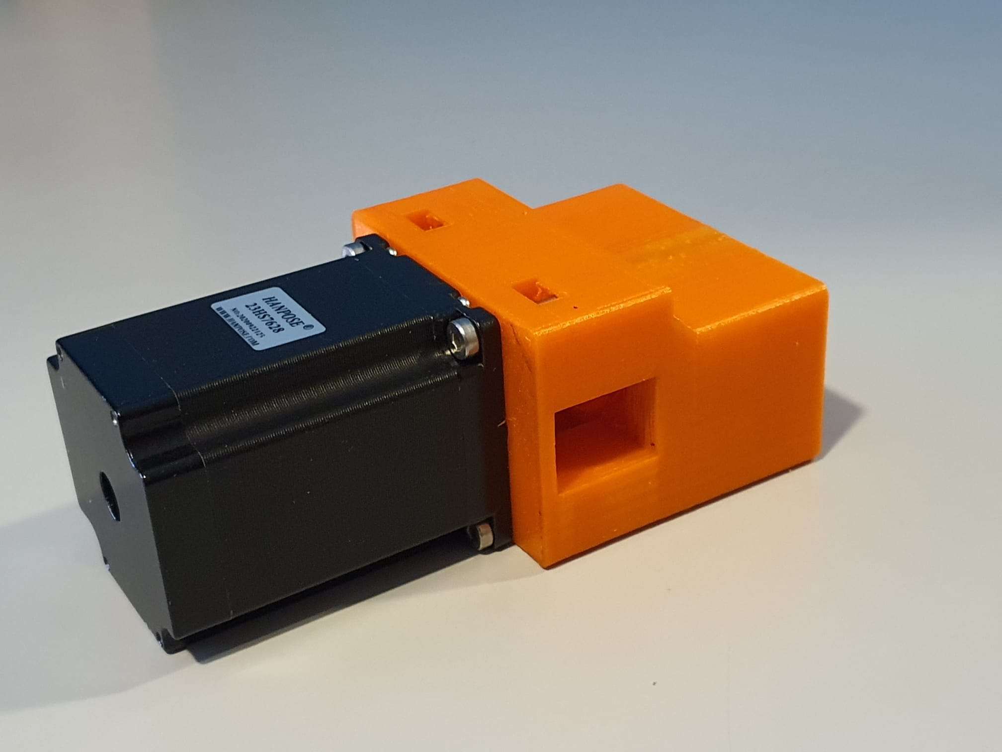
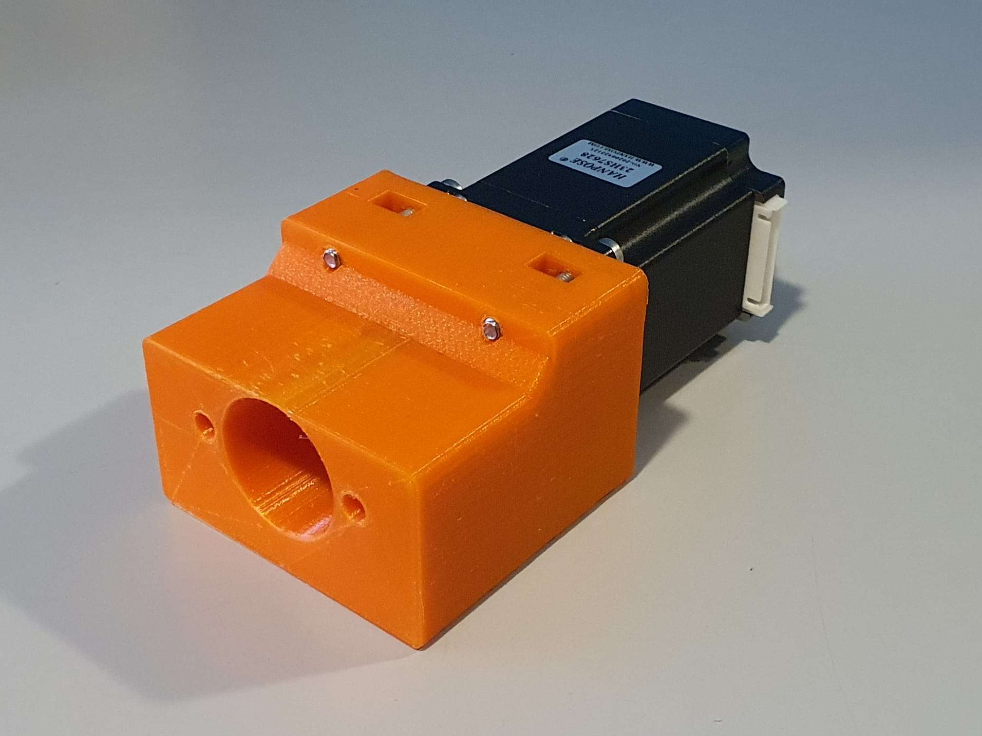
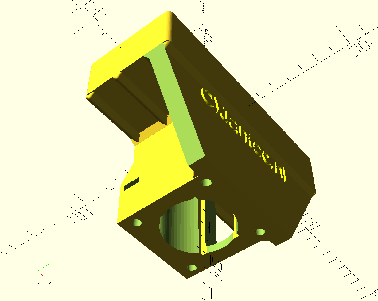
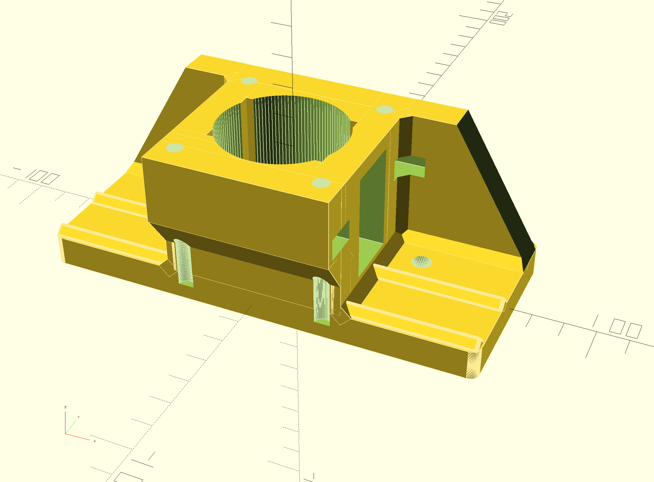
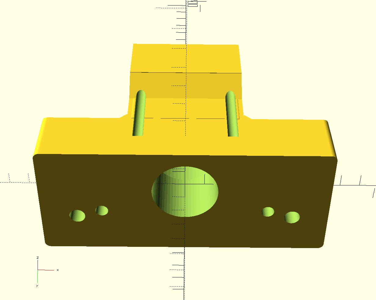
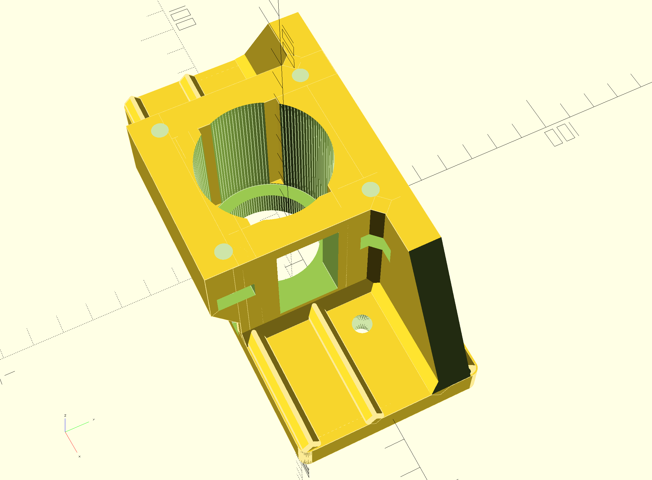
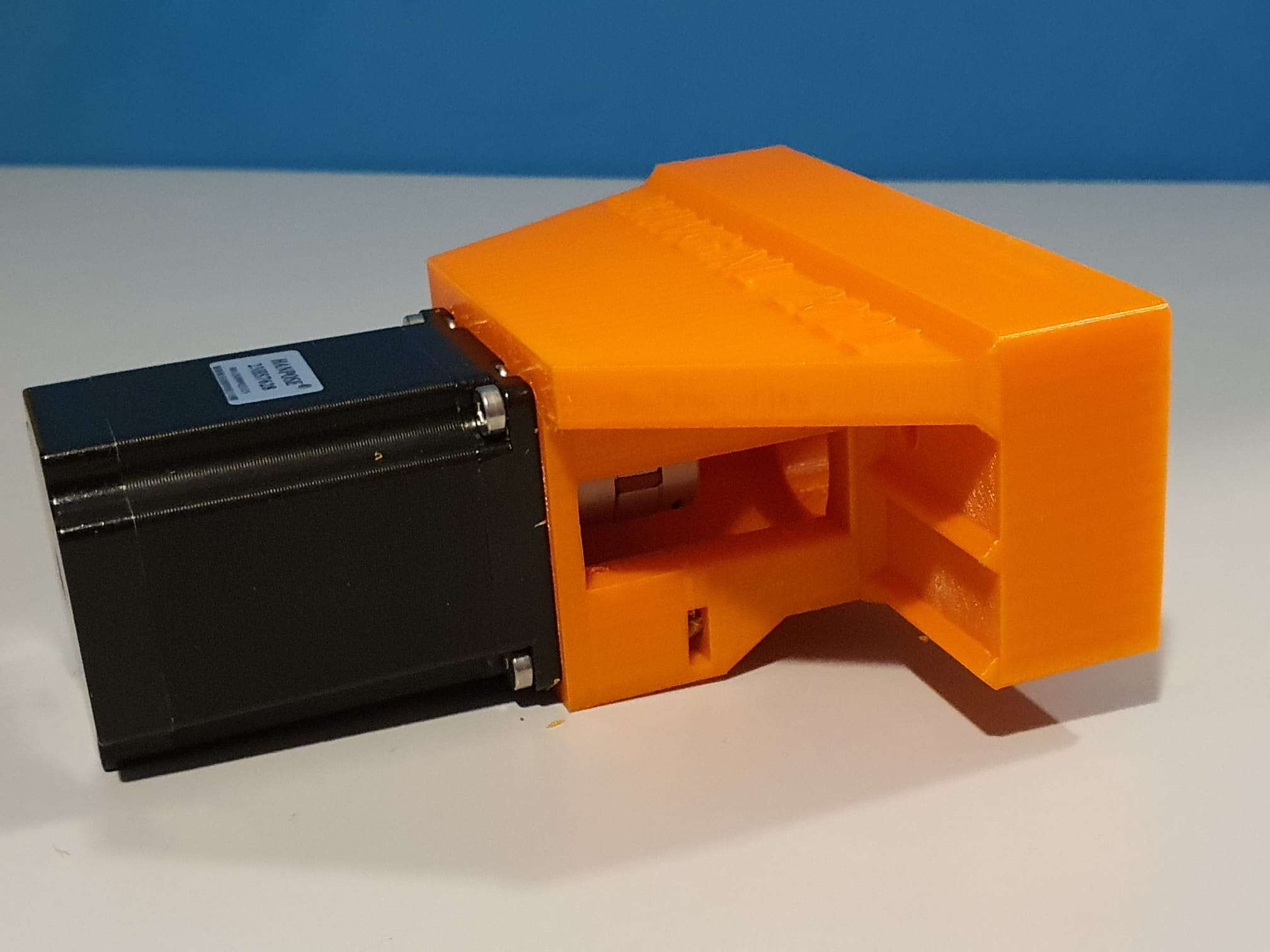
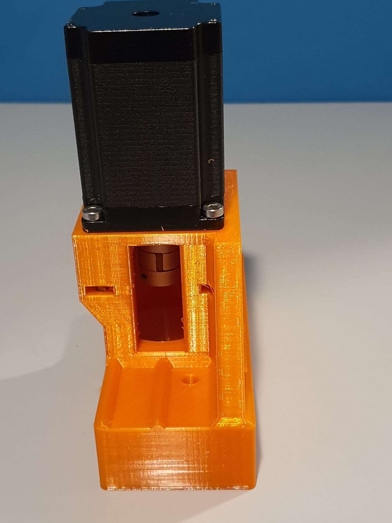
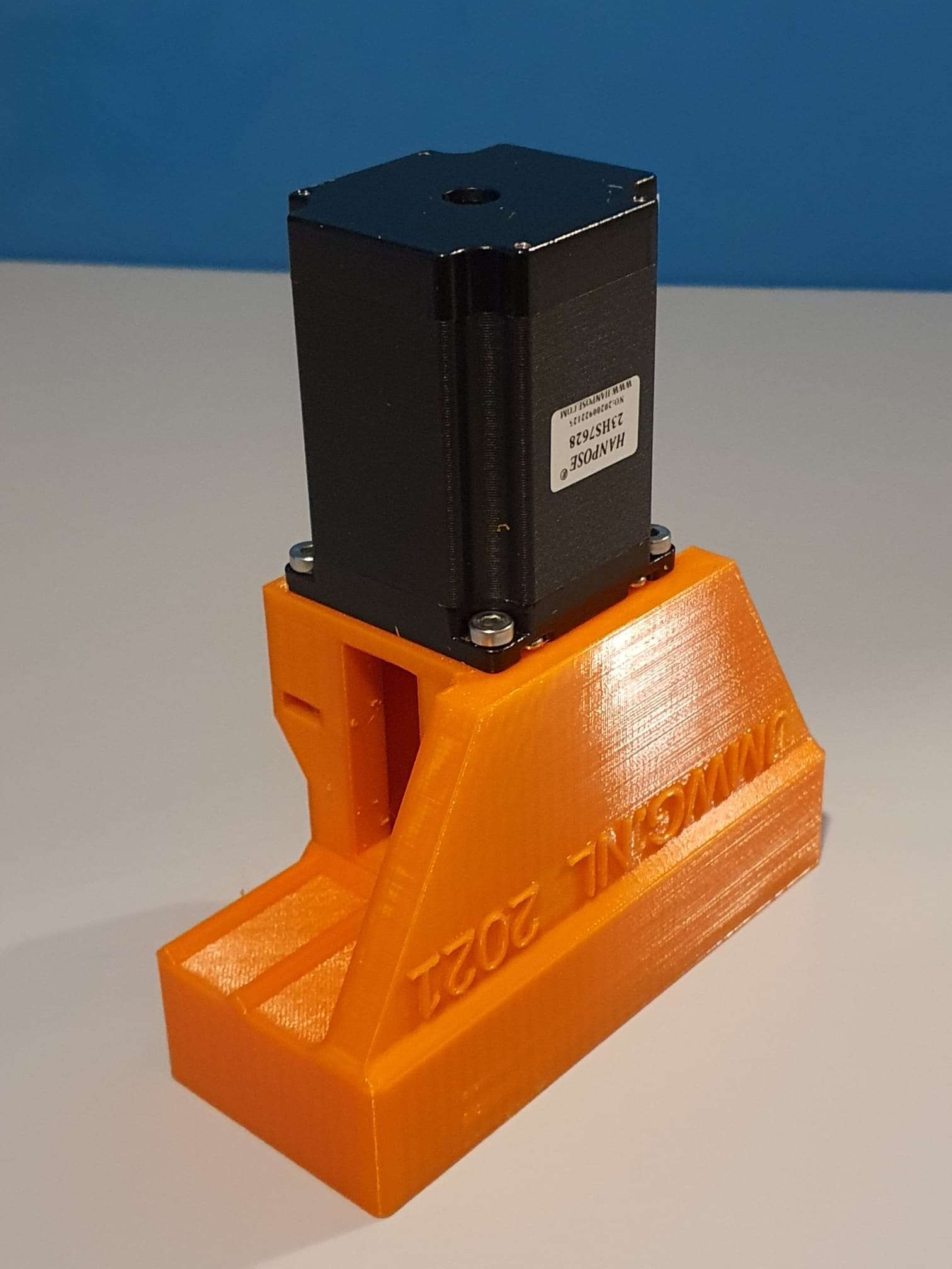
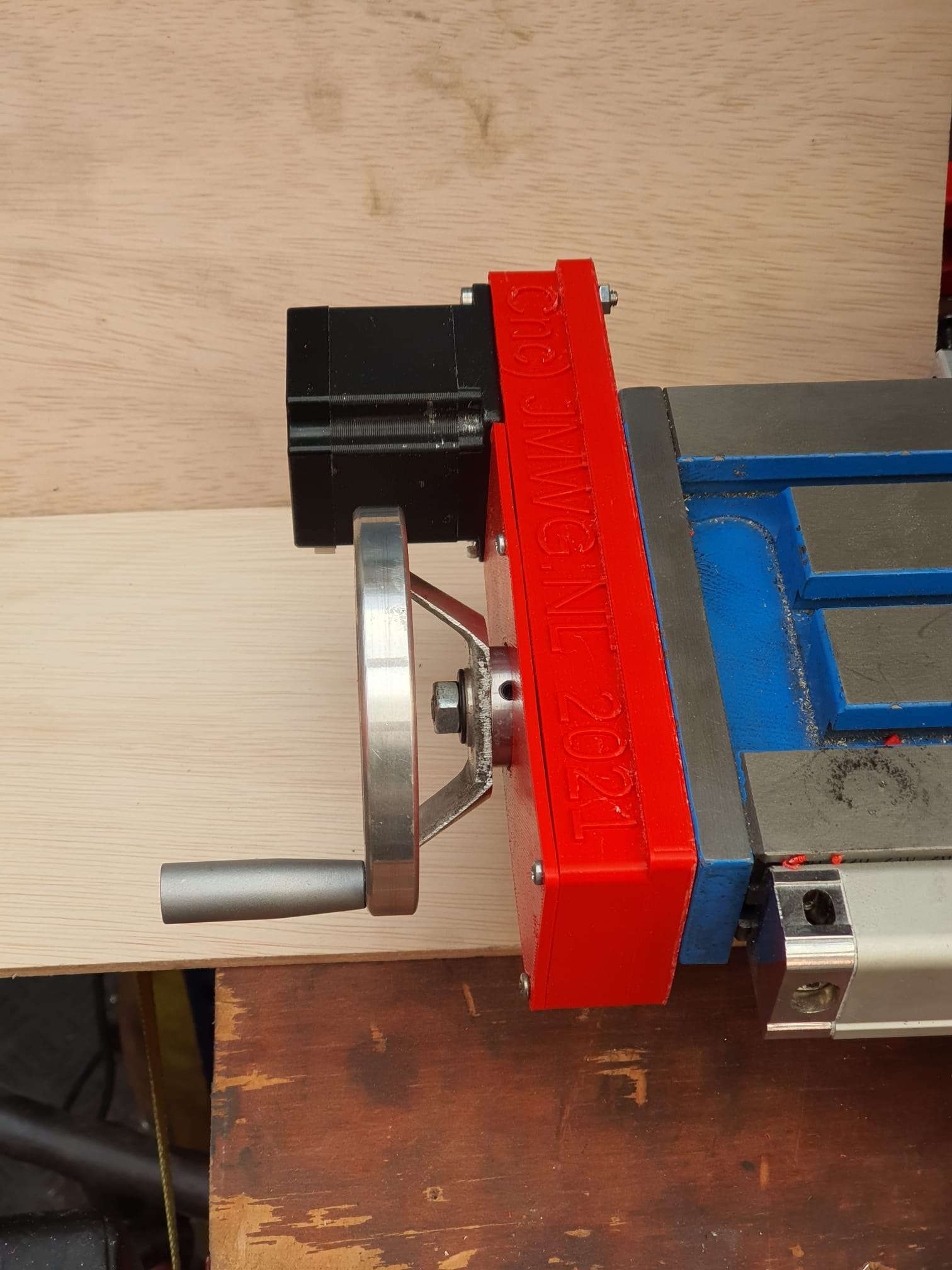
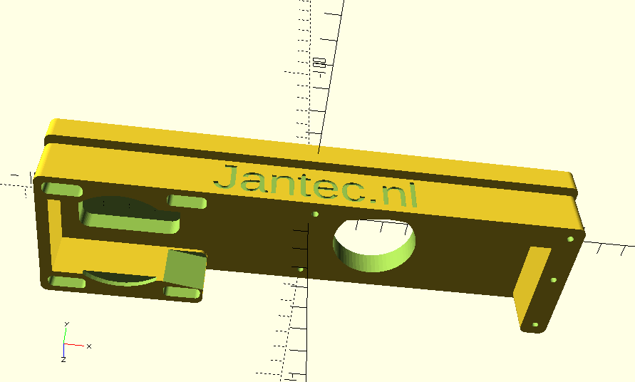
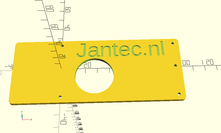
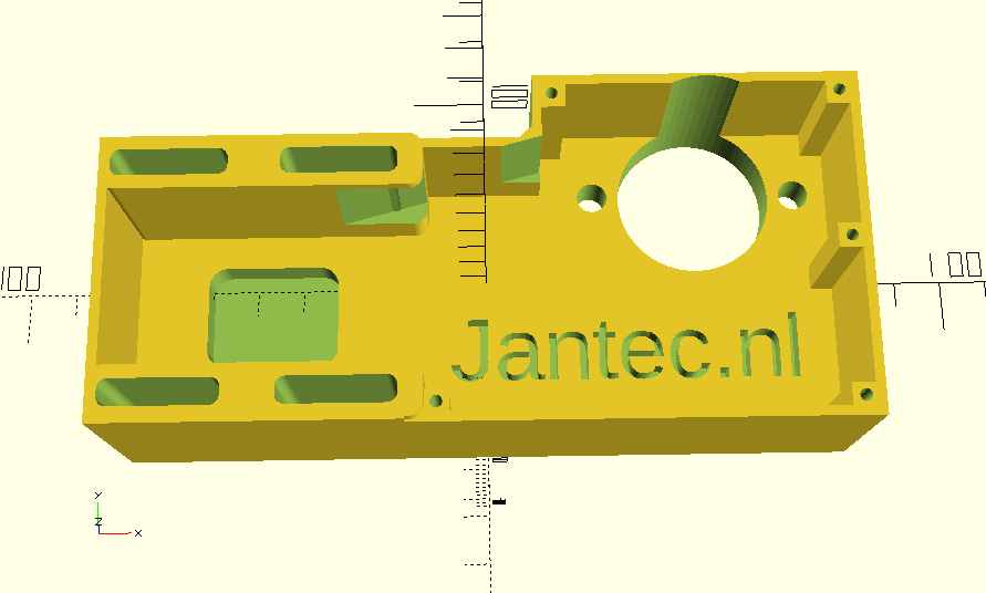
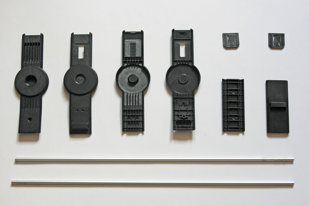
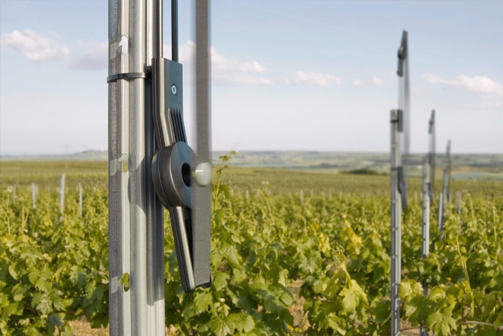
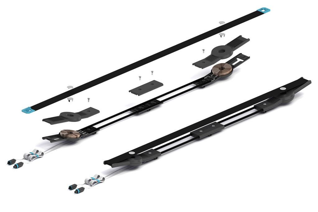
Wolfang GA200 4k videocam smallrig STL download

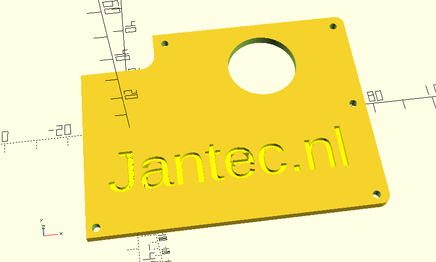
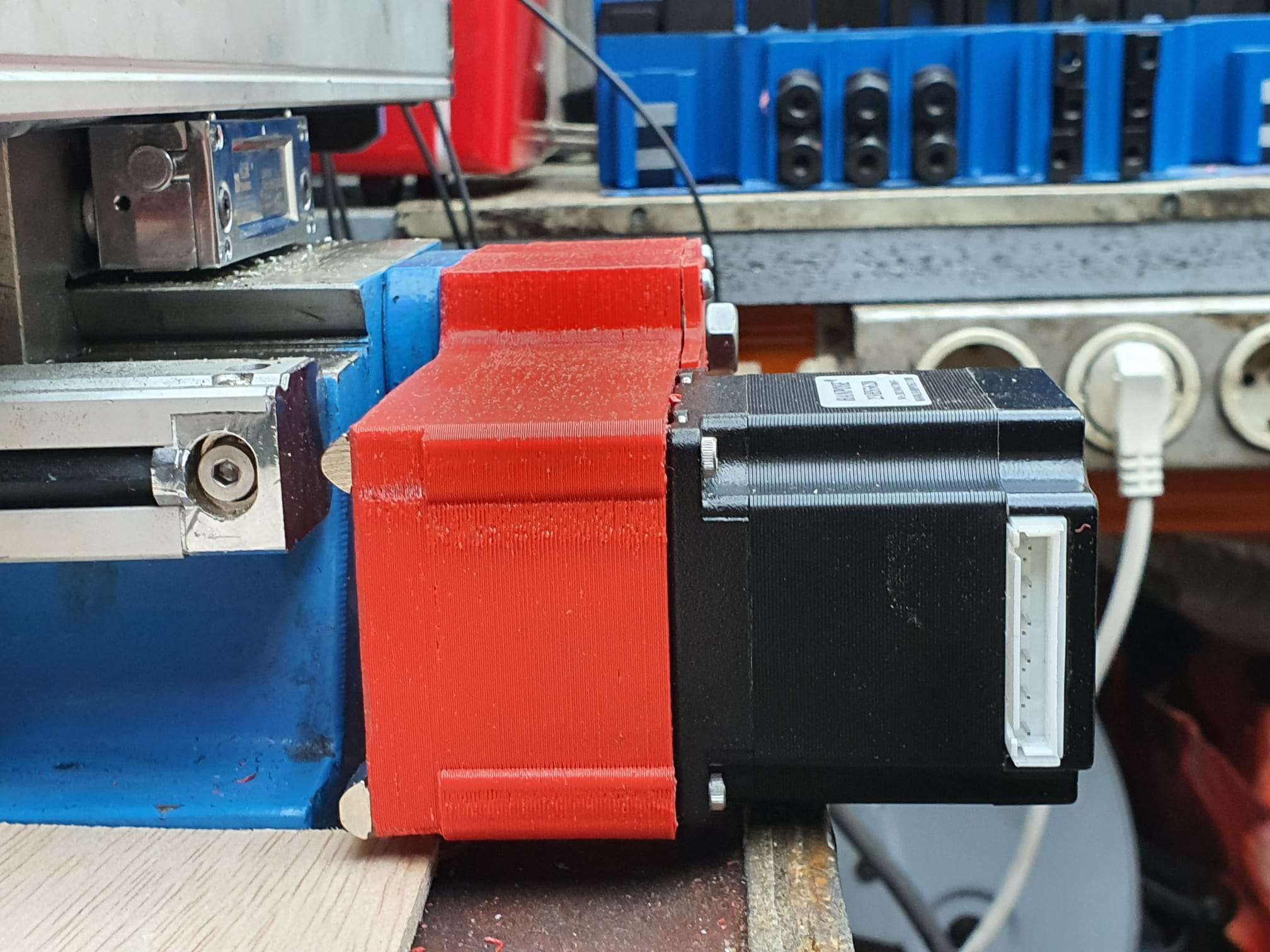
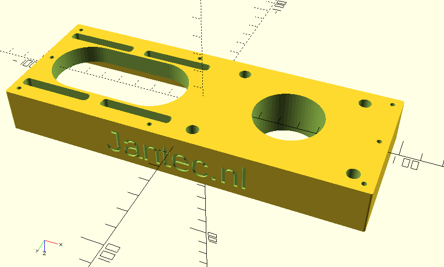
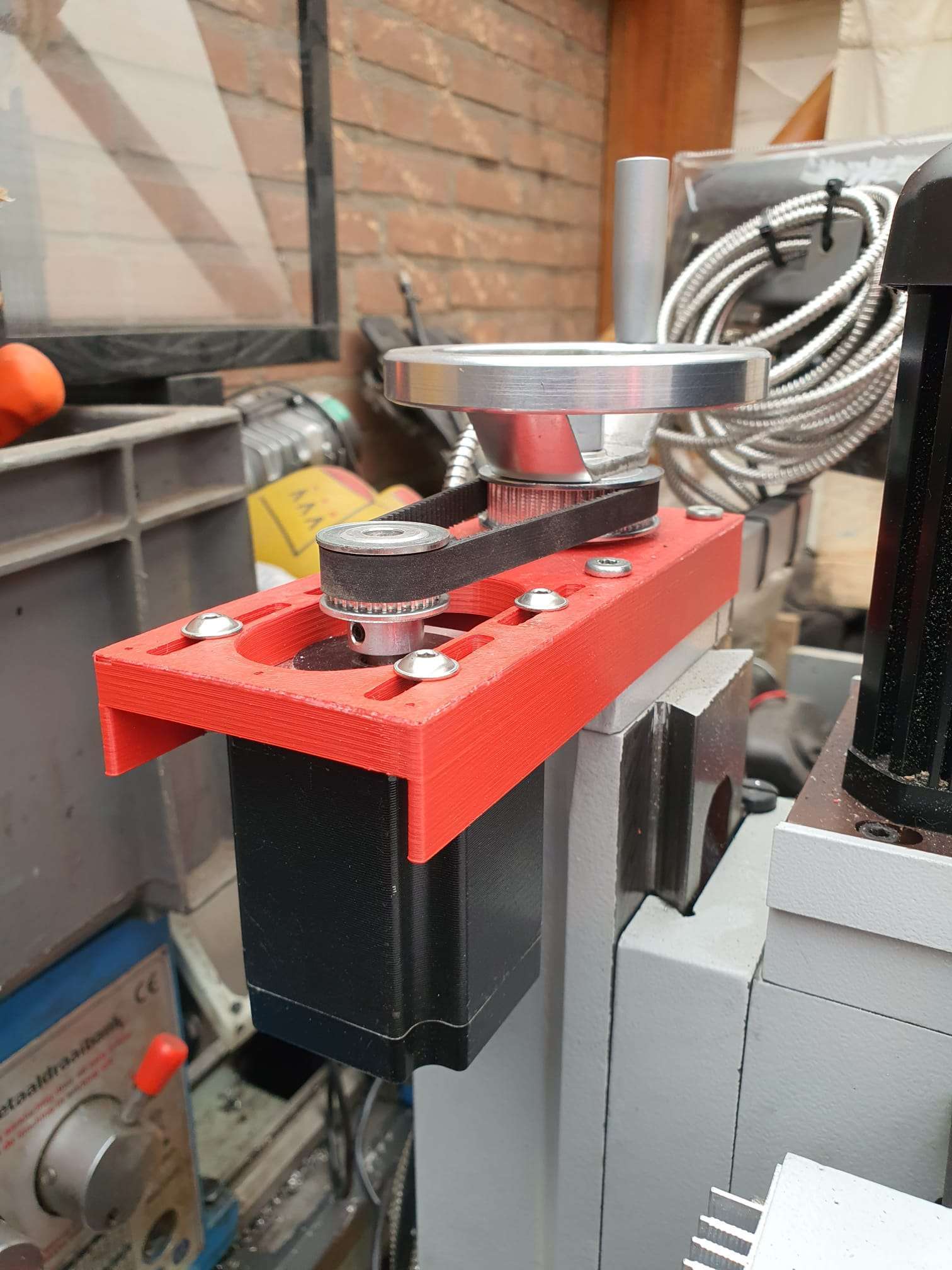
Wolfang_GA200_4k_videocam_smallrig_20260318_V11G_jantec.nl


Please donate $1 to my paypal account if you use this original jantec.nl design  -)


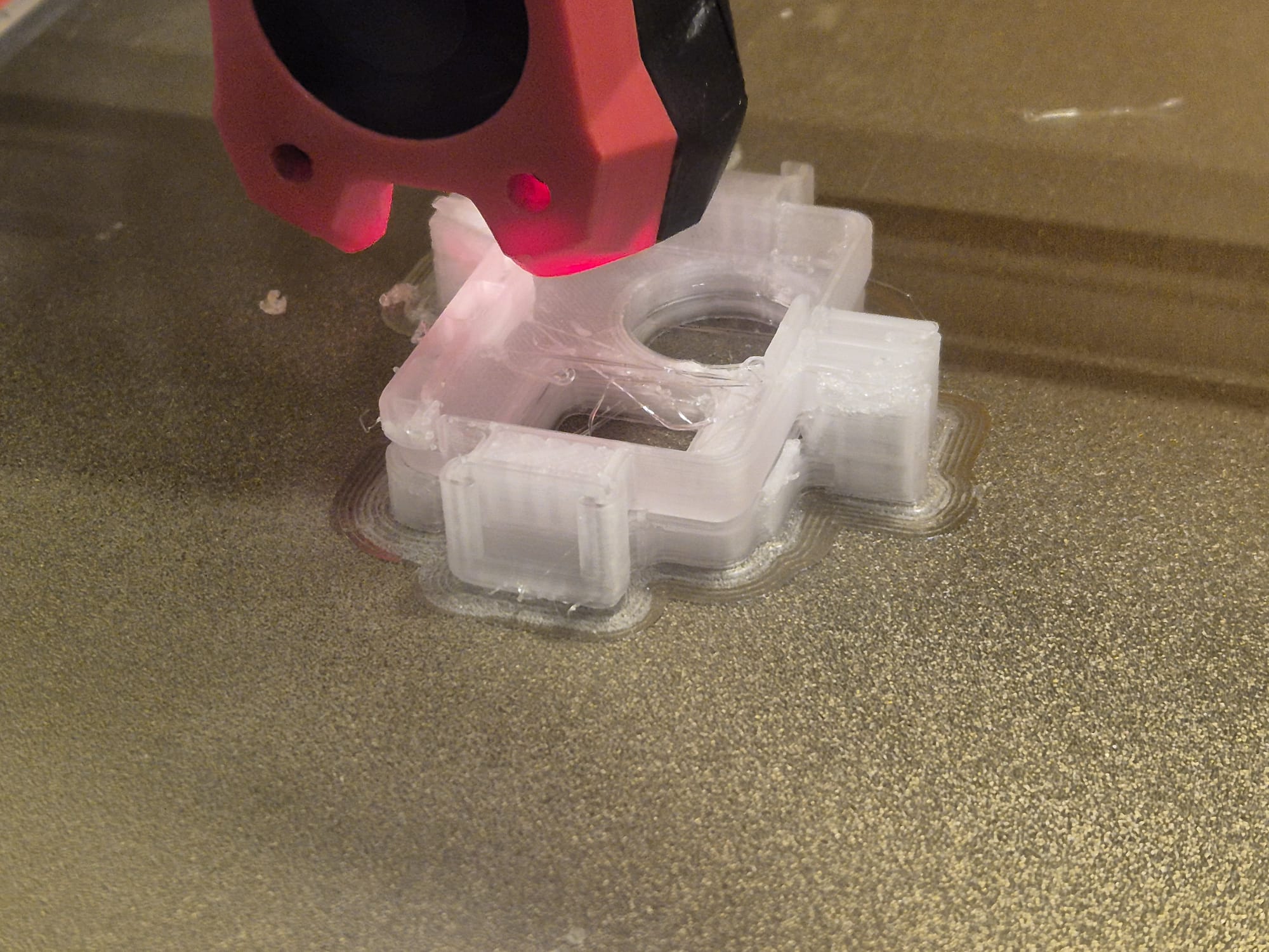
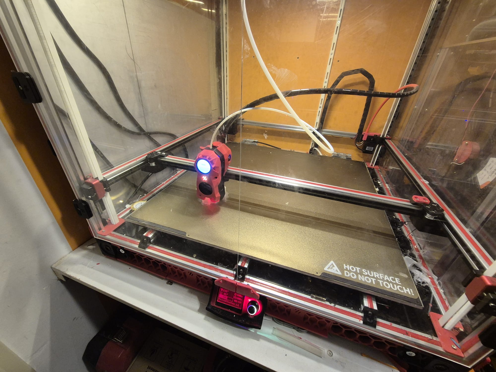
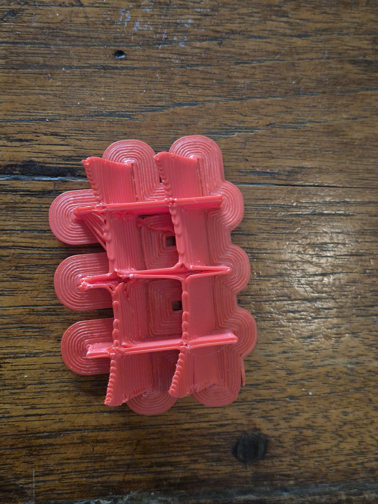
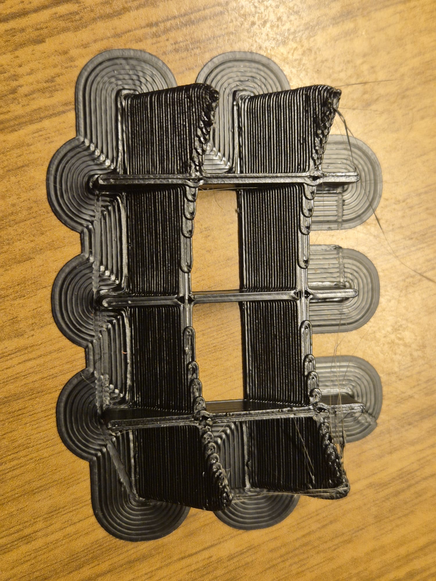
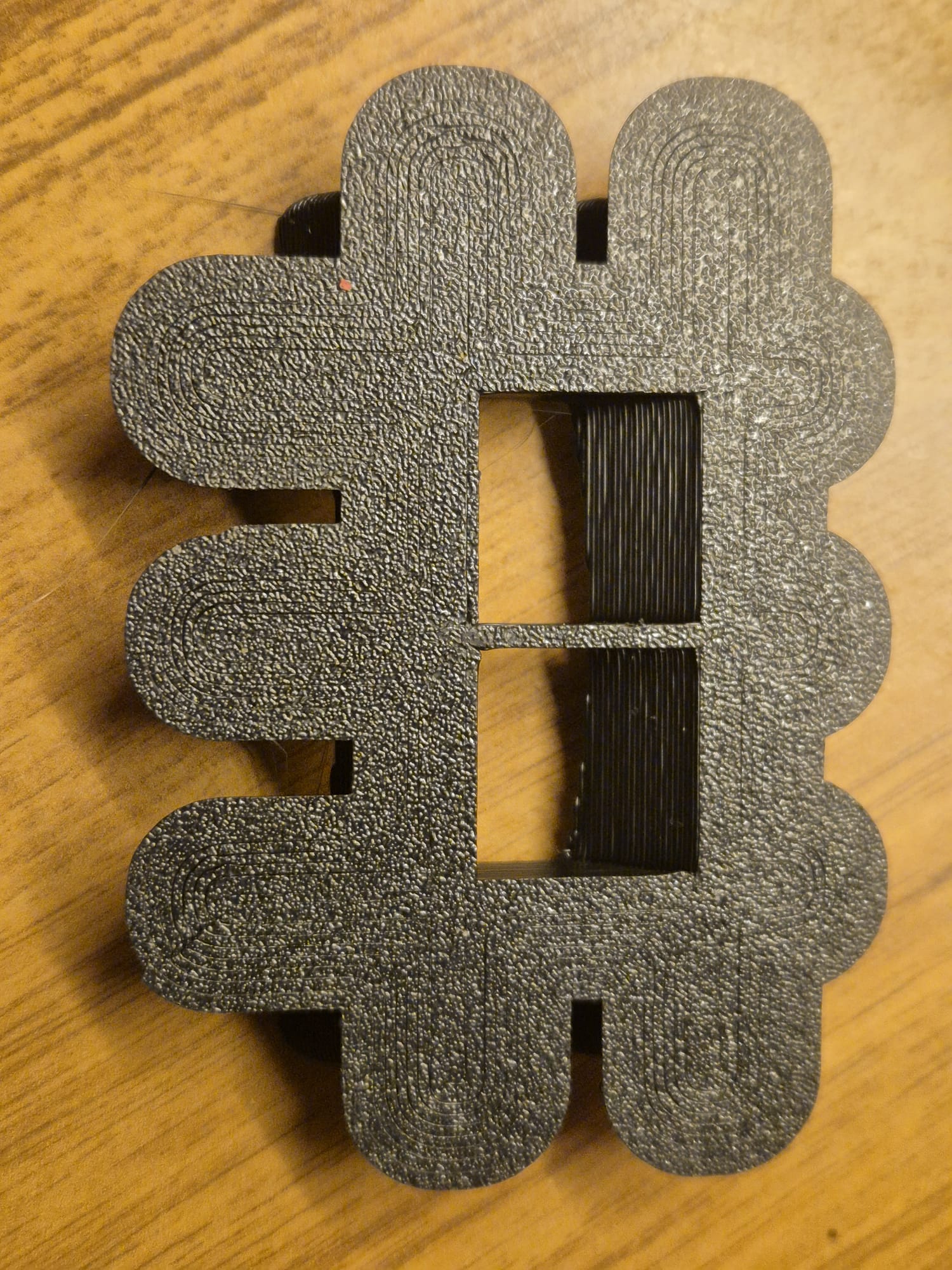
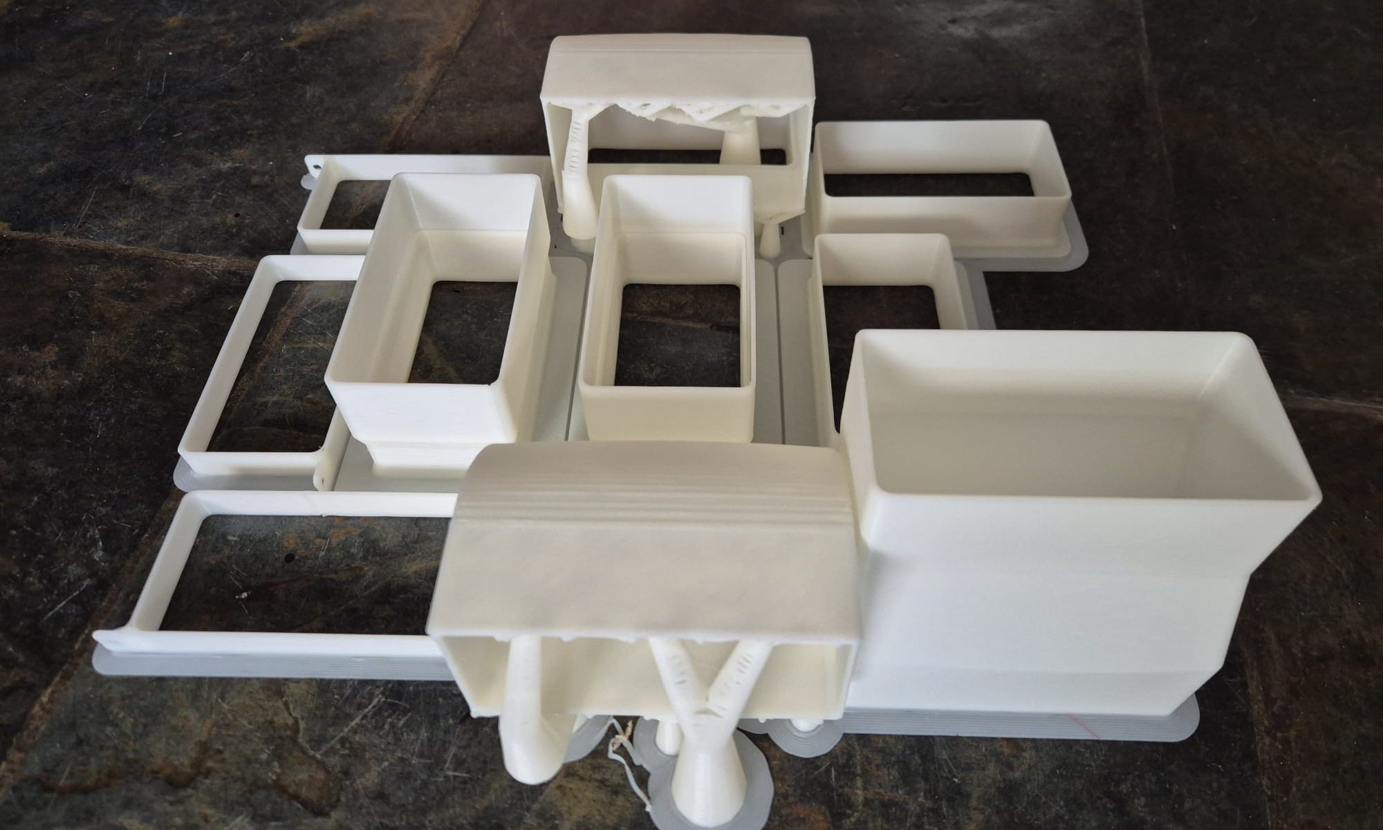
Printed on Voron 600 @ 0.3 mm LH and 0,8mm nozzle, transparant PETG. Hispeed in 1 hour at 100% infill, front down, brim 0.2 mm thick, 10mm wide. Supports everywhere in matrix mode @ 10mm wide, big gap 0.5mm top of Z and 1.2 mm on X/Y spacing. Temp 235 deg nozzle, 85 deg bed. 100% fan except for 1st 3 layers.

STL download 3-D printbare plastic vervangingshulzen voor ‘old school’ akoestische gitaartuners

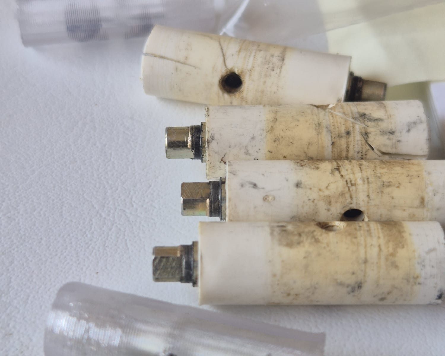
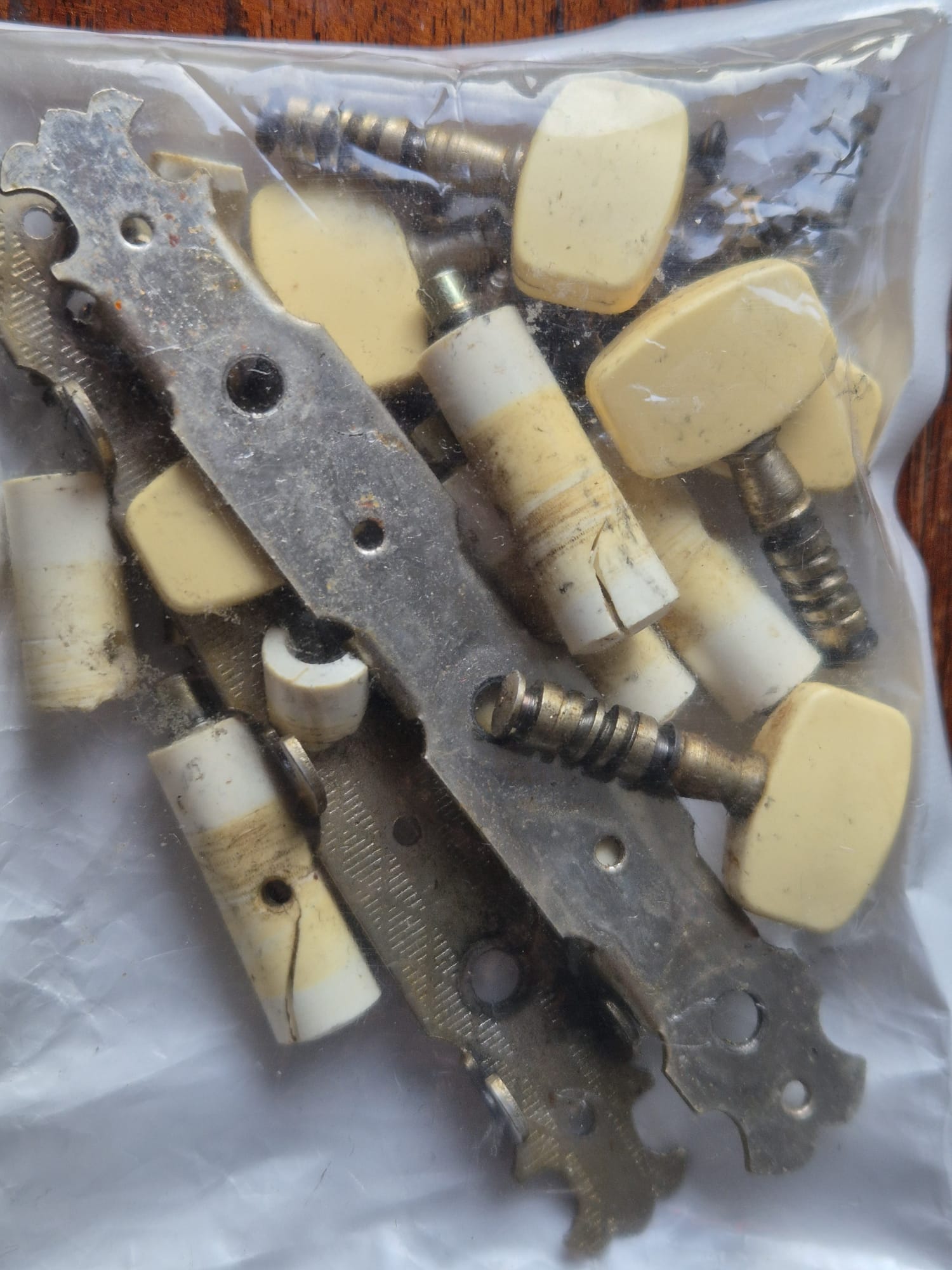
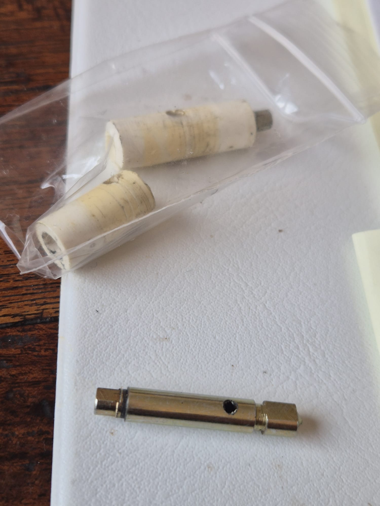
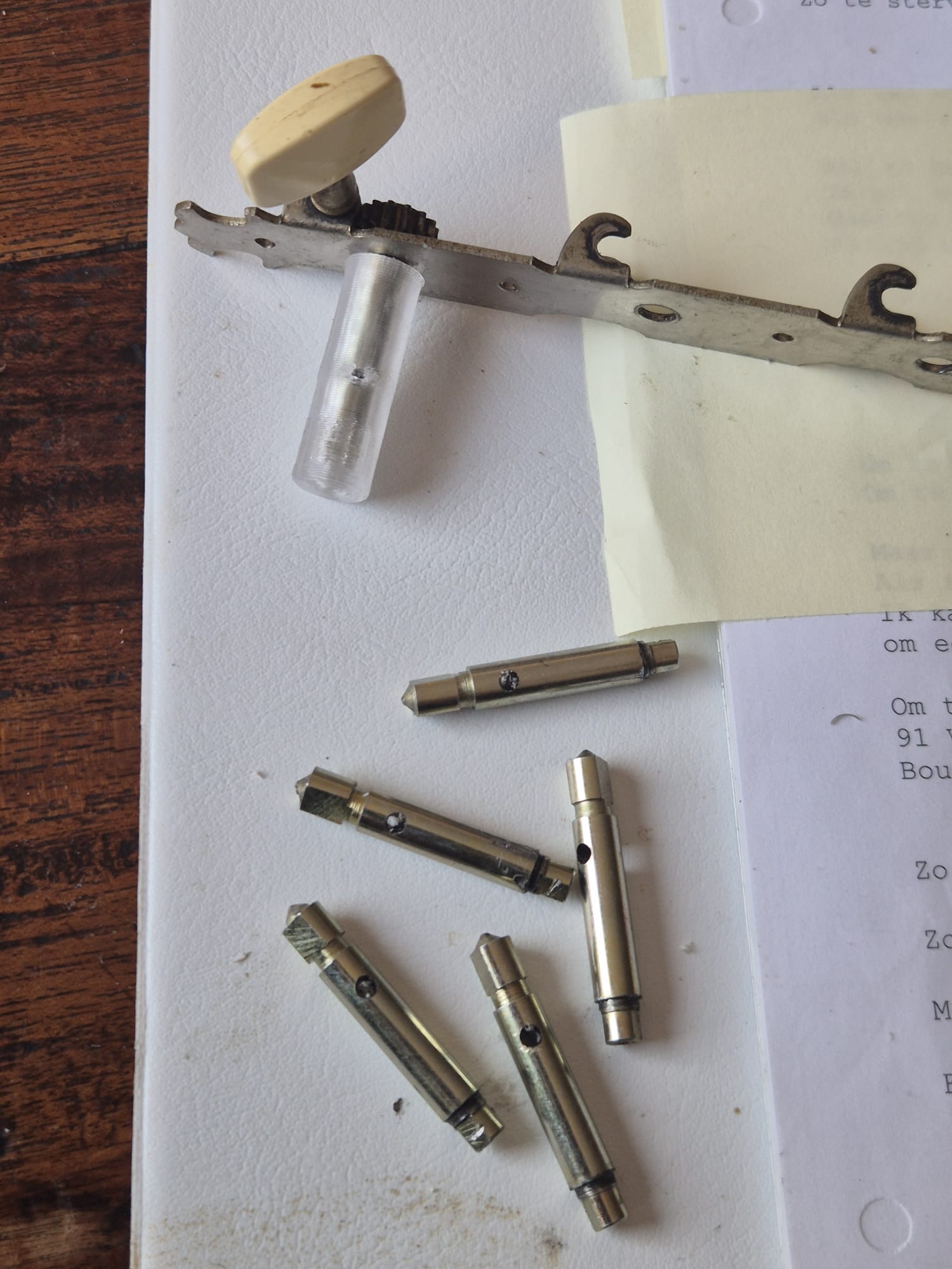
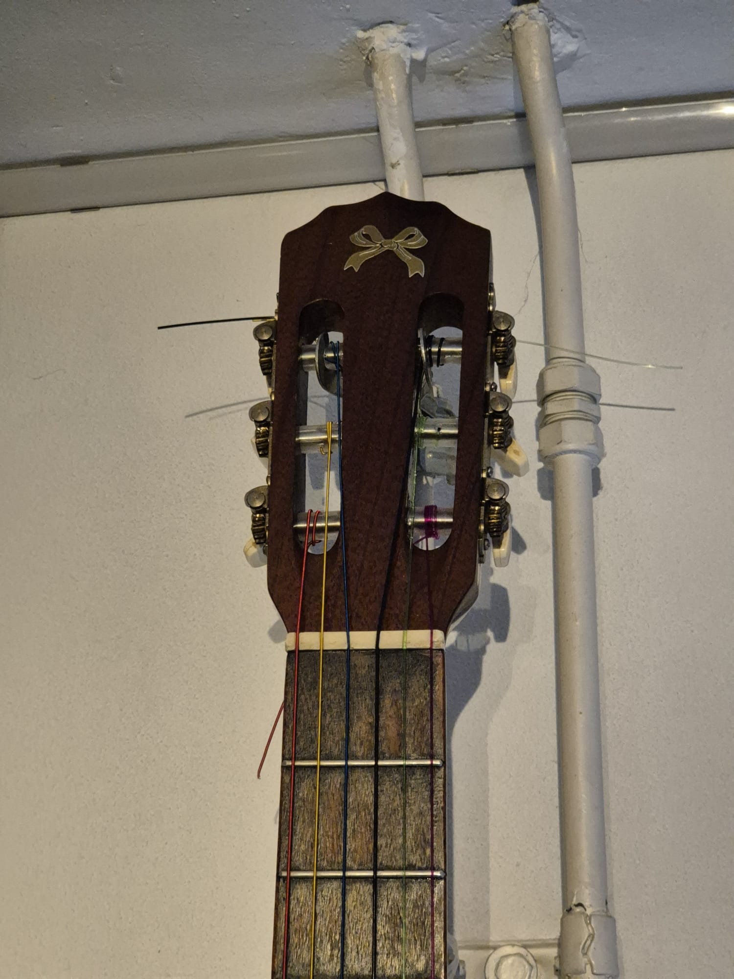
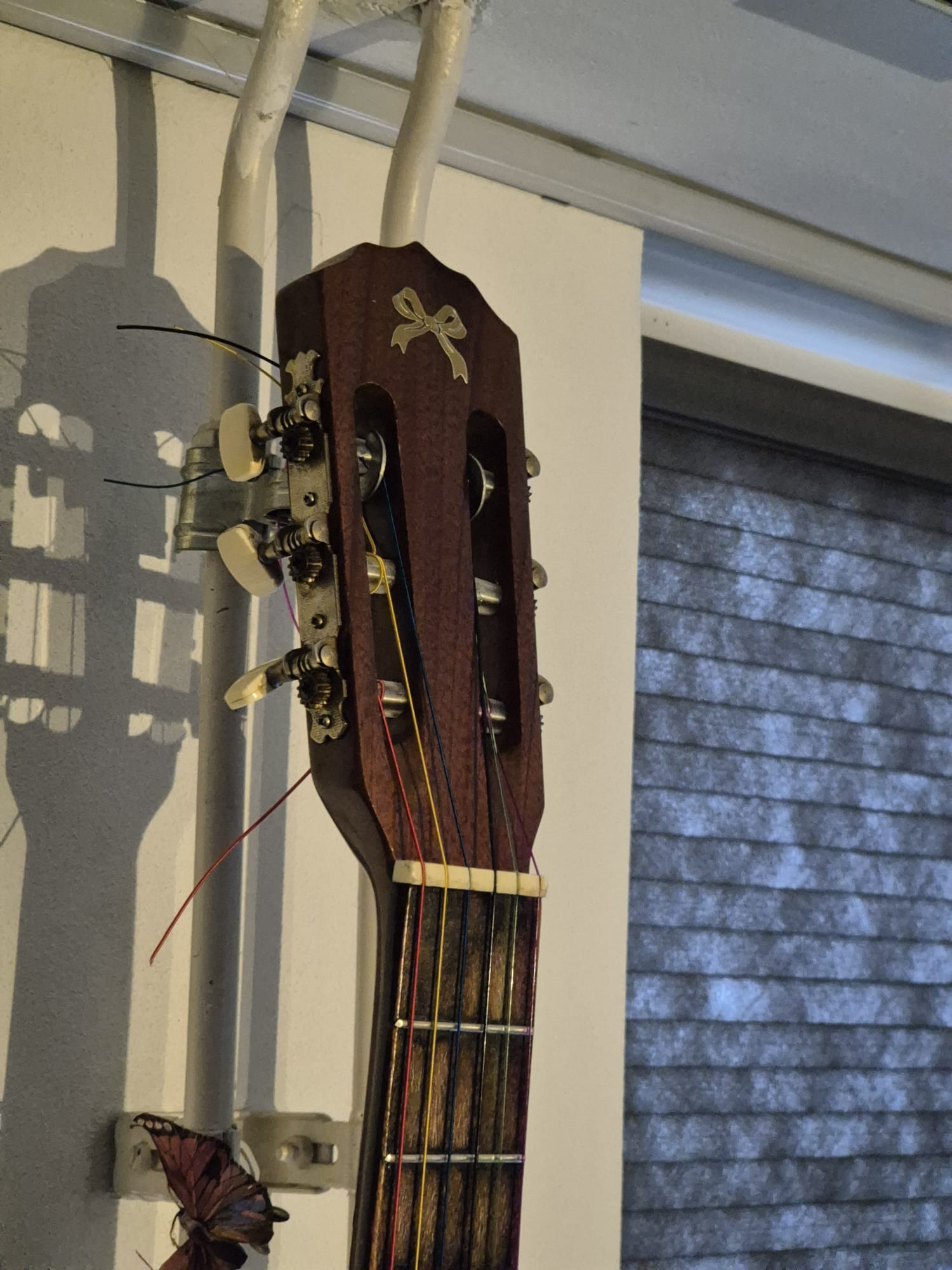
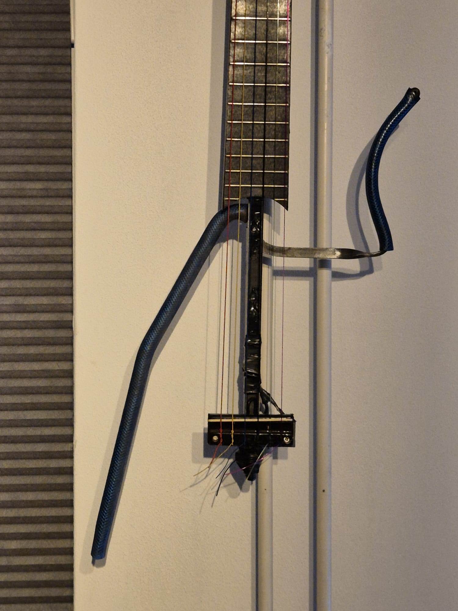
Een van mijn zeer oude zelfgemaakte elektro-akoestische gitaren had kapotte stemmechanieken. Ik wilde geen nieuwe bestellen, omdat de mechanica nog in orde was, alleen de plastic hulzen om de tunerassen waren kapot.

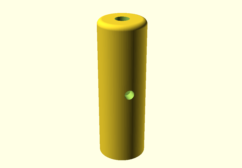
In Openscad ontwierp ik 3D-geprinte hulzen die om de metalen stemmechanieken passen.

acoustic_old_guitar_tuner_plastic _replacement_part_5.9mmID_10mmOD_30mmL_V3_20260305

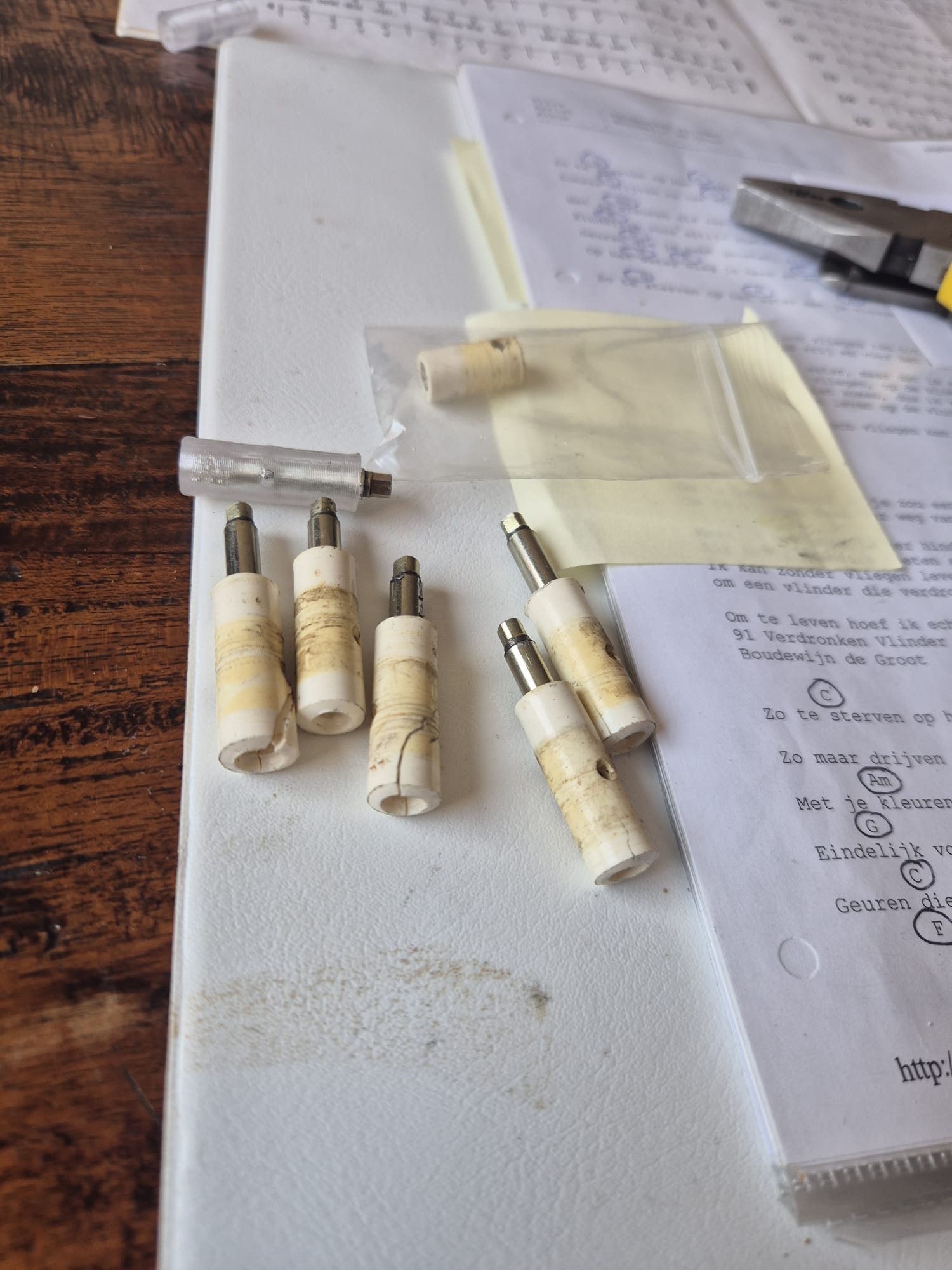
Ik heb 6 hulzen in transparant PETG geprint op de Voron 600 (0,8 mm spuitmond, 0,3 mm LH, 235 graden spuitmond//85 graden bed).

Geen steunen, hoewel ik wel een stevige rand rond de as heb gebruikt. Ik heb de hulzen één voor één geprint, elk in 7 minuten.

De oude assen zijn uit de metalen assen getikt. Ik heb mijn bankschroef gebruikt en de bek van de bankschroef net genoeg geopend om de assen uit de hulzen te tikken.

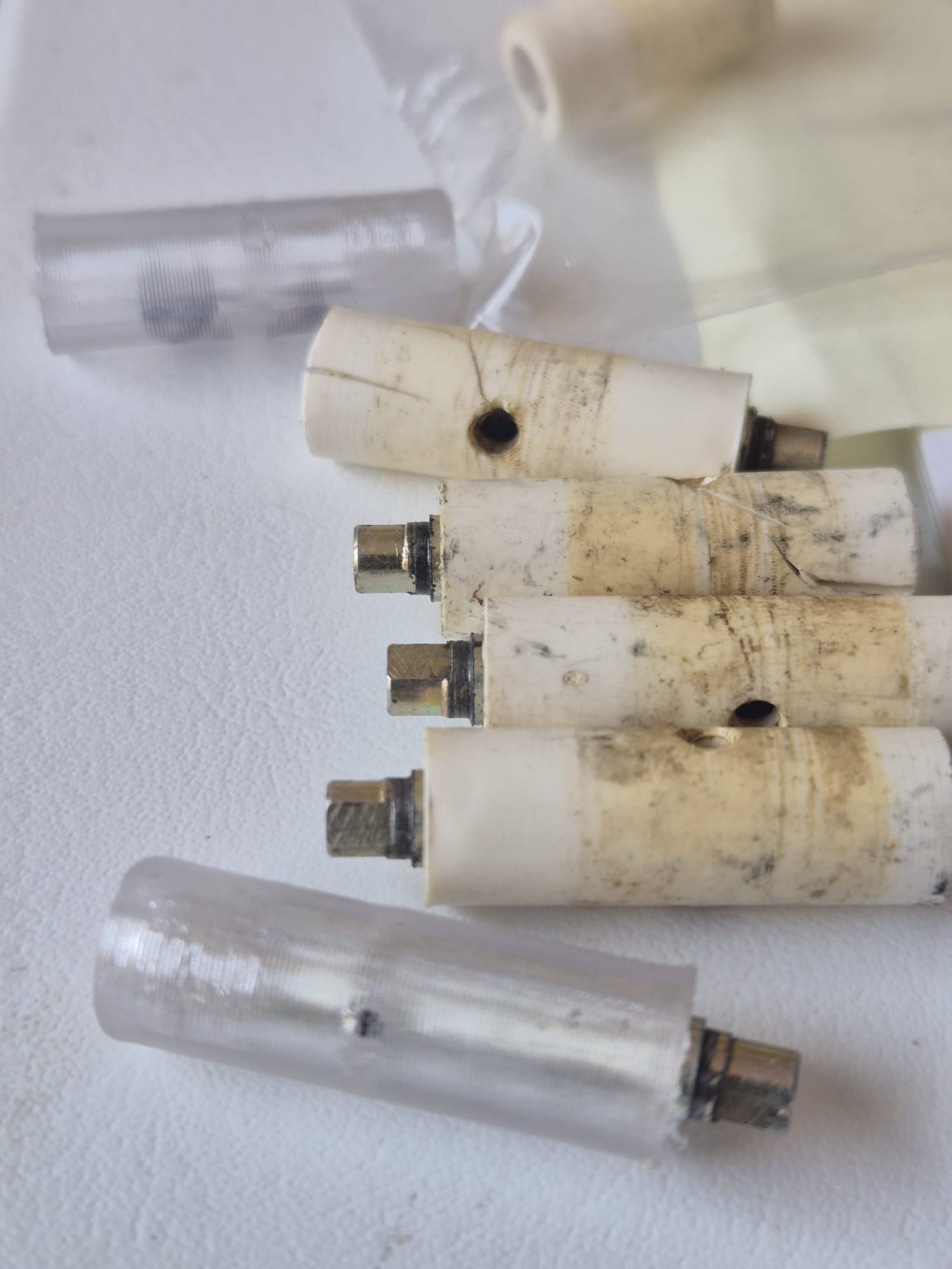
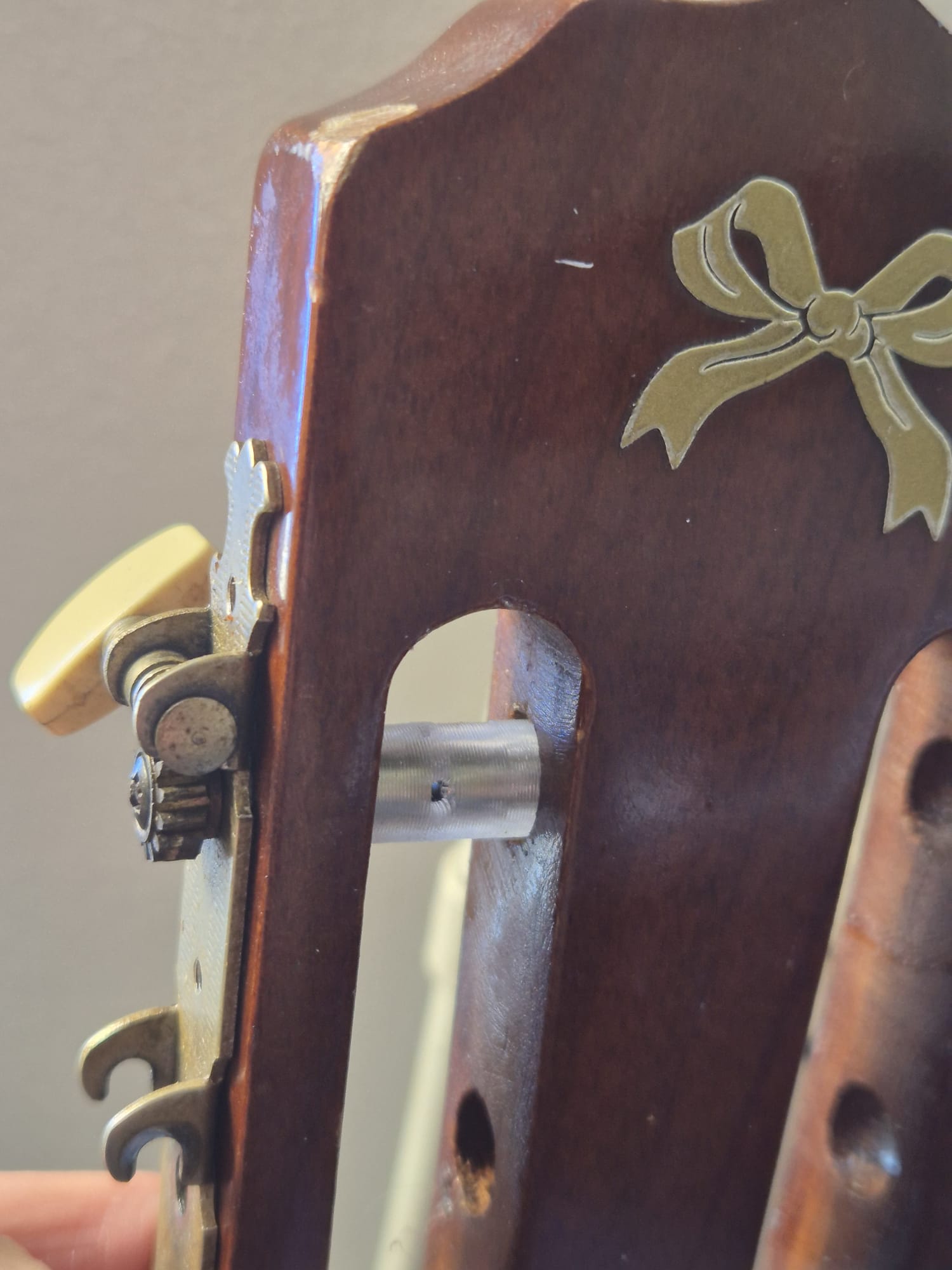
Het monteren van de hulzen rond de assen is vrij eenvoudig, omdat het gat in de assen en hulzen op elkaar kan worden uitgelijnd dankzij de transparantie van het PETG-materiaal.

De assen passen gemakkelijk in de hulzen, hoewel ik de bankschroef heb gebruikt om de as de laatste 1-2 cm erin te duwen, vanwege de strakke pasvorm van de as in de uitsparing van de binnenkant van de huls, waardoor de huls de cirkelvormige beweging van de assen volgt bij het stemmen van de snaren.

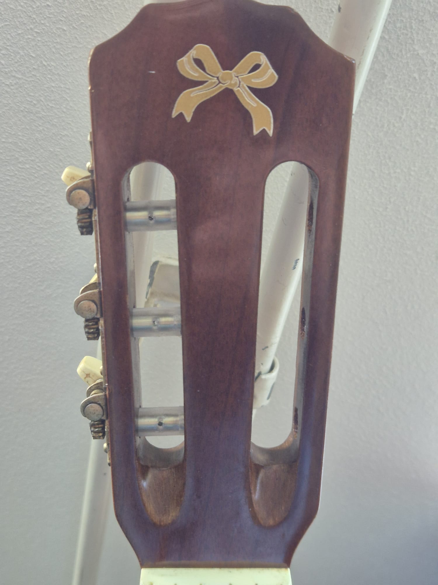
Bij het installeren van de stemmechanieken heb ik wat vaseline aangebracht rond de plastic hulzen waar ze in contact komen met de gaten in het hout van de losse kop, zodat de hulzen niet vast komen te zitten.

Het proces van het demonteren en monteren van de hulzen en de stemmechanieken spreekt voor zich. Bekijk de onderstaande foto’s!

Ik heb trouwens 2 versies van de hulzen gemaakt.

De versie die ik op mijn snelle Voron600 heb gebruikt, is aan de binnenkant iets breder (asdiameter +0,4 mm).

Dit is nodig omdat kleine gaatjes op mijn Voron600 met het 0,8 mm-mondstuk altijd kleiner worden geprint dan ontworpen.

Als je de hulzen met een nauwkeurige 3D-printer wilt printen, vind je HIER het exact passende ontwerp: acoustic_old_guitar_tuner_plastic _replacement_part_5.6mmID_10mmOD_30mmL_V3_20260305

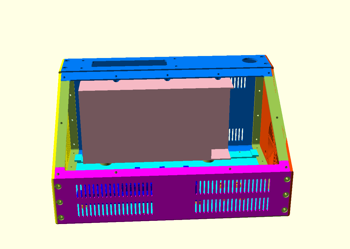
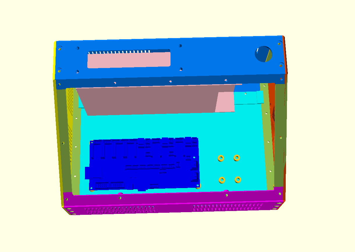
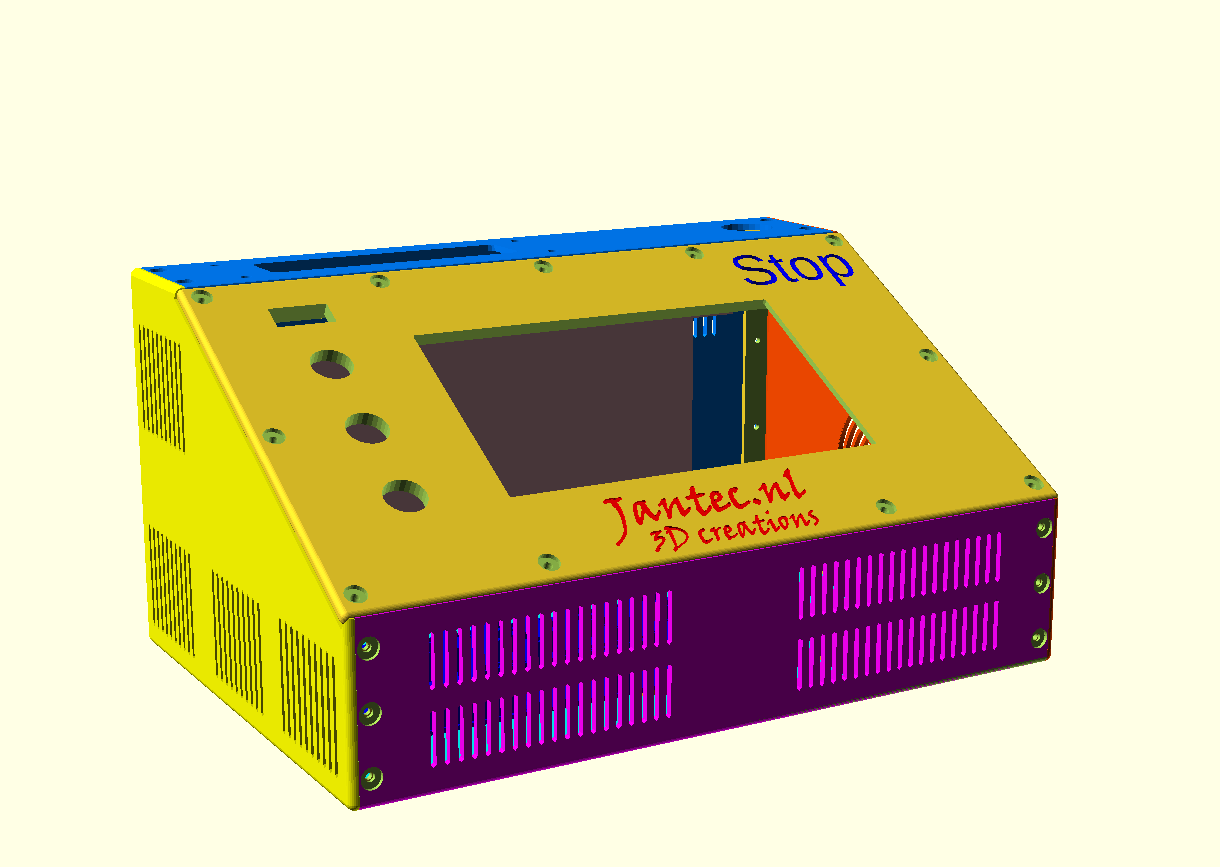
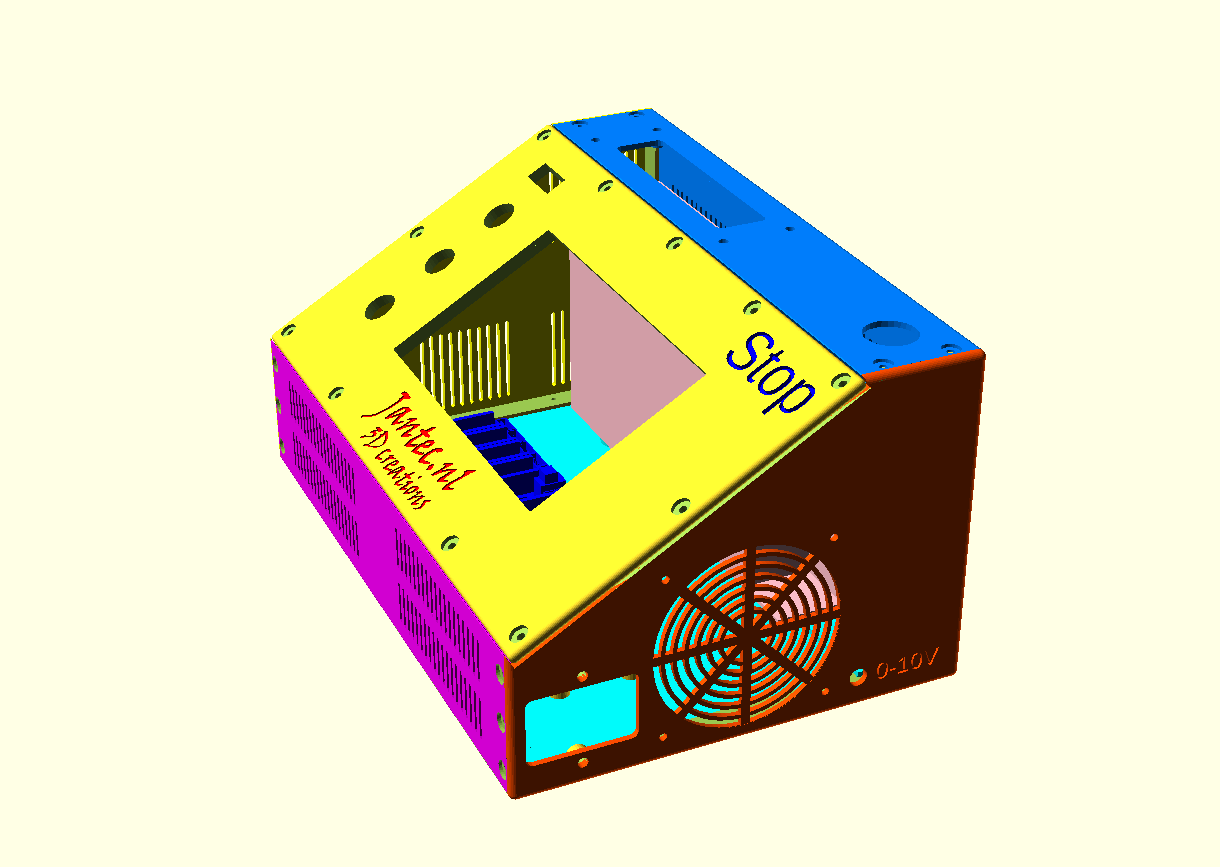
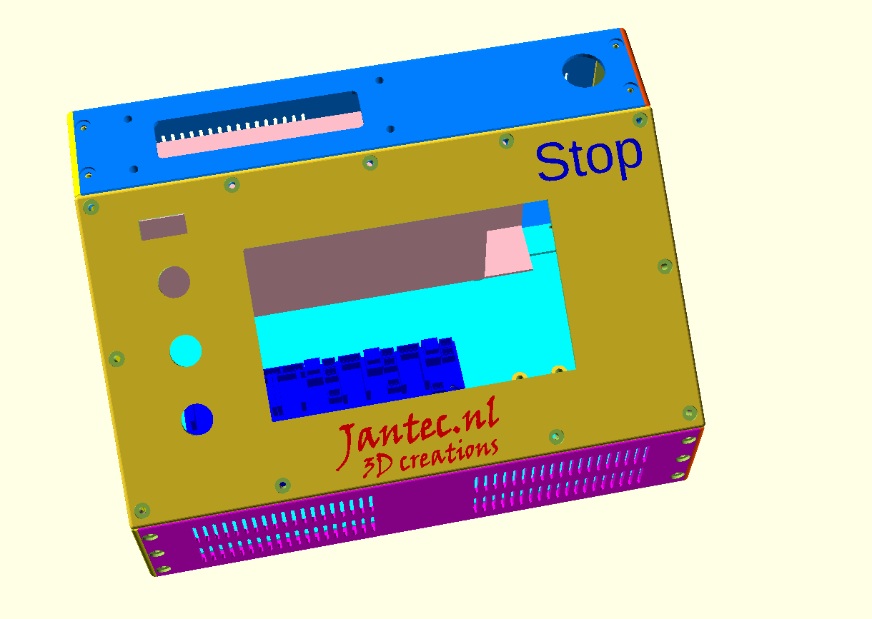
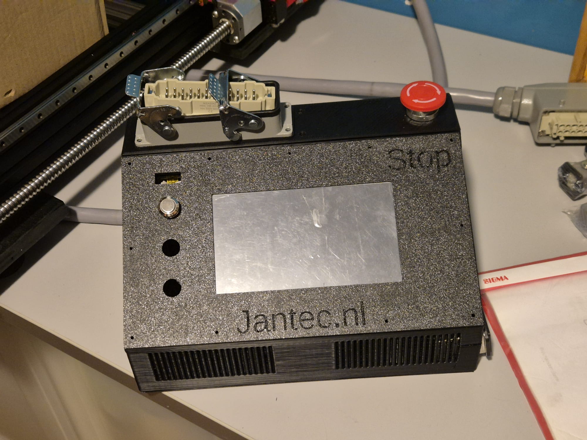
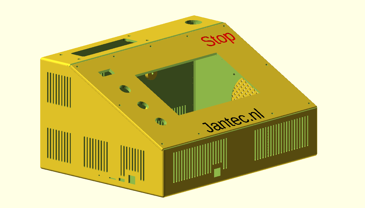
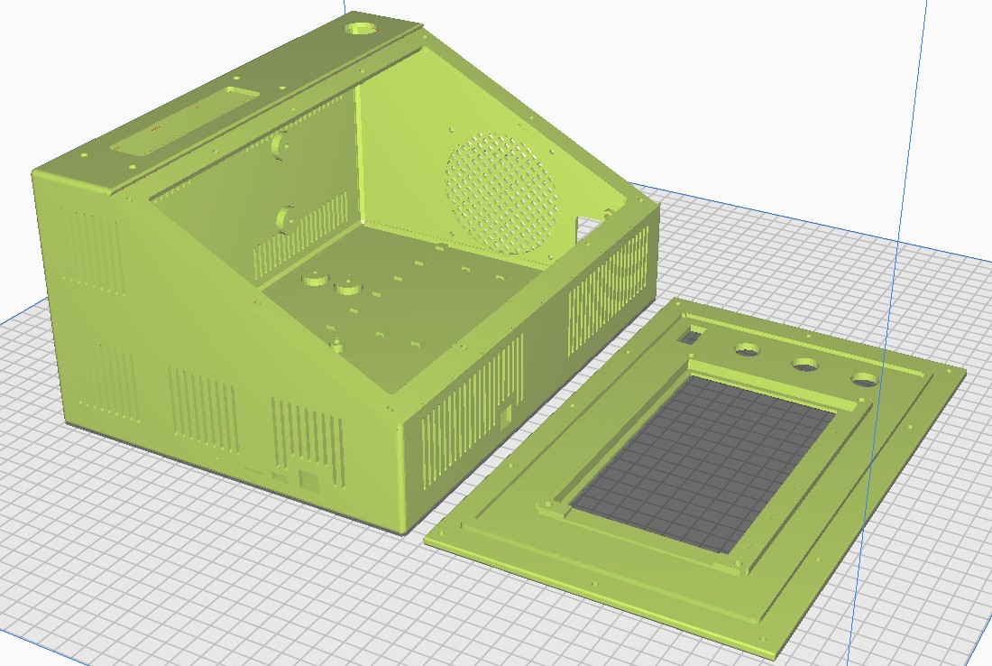
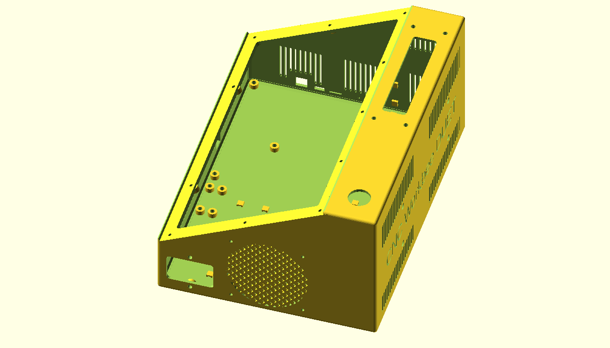
CNC besturingskast gratis STL download Duet workbee Mellow FLY CDY met voeding, paniekknop, multiconnector en Fysetc 7 inch Duepanel touch-LCD

DOWNLOAD CNC_controller_box_6_parts_V2_C)JANTEC.NL_20251102

Please donate $1 to my paypal account if you use my original designs  -)

DE CNC CONTROL BOX

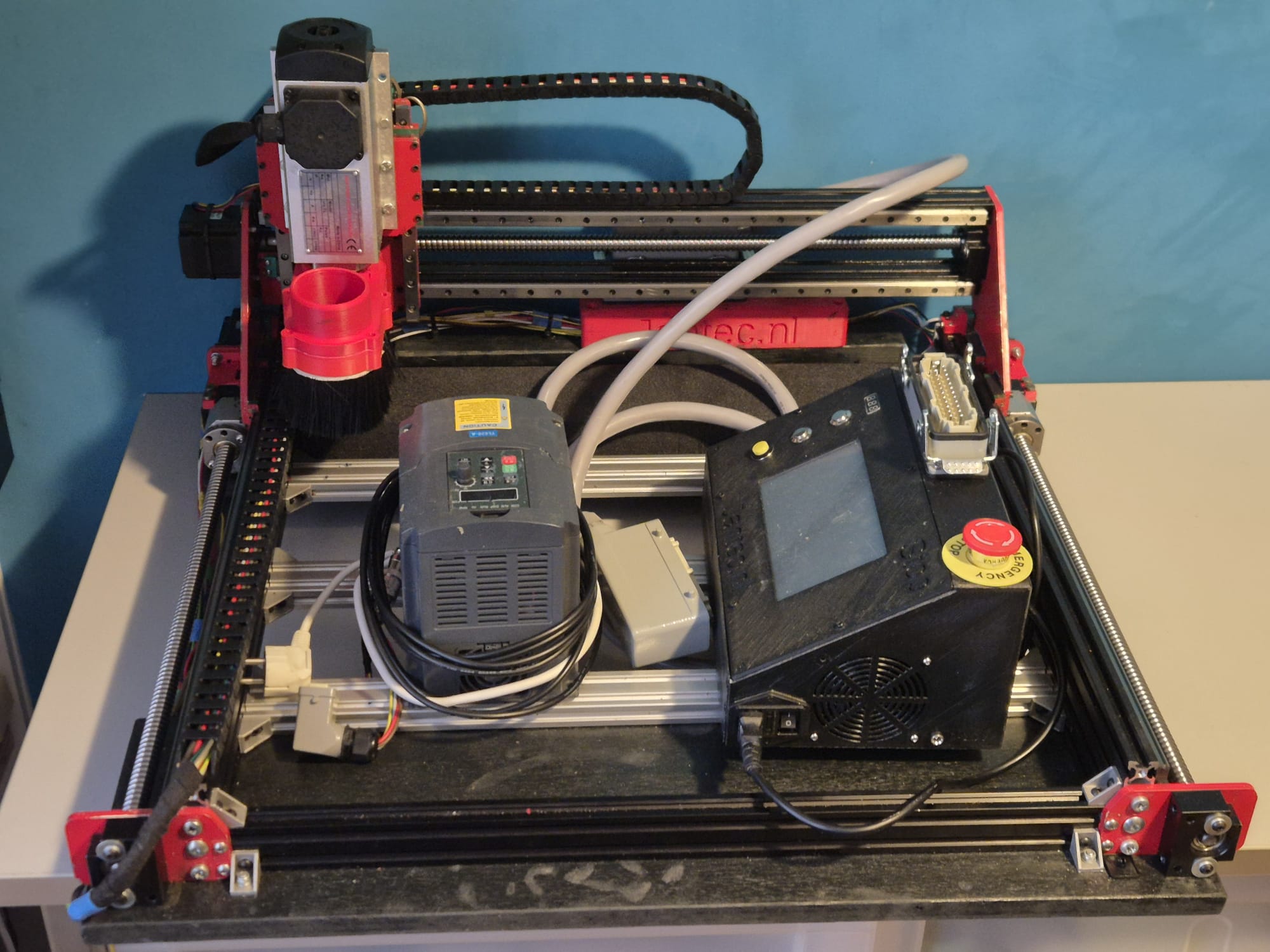
DE Indymill CNC machine met erop de frequentieregelaar links en de CNC controller rechts

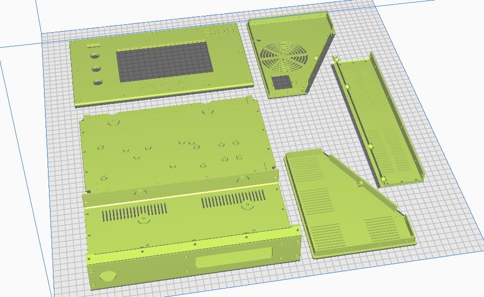
Download het ontwerp van de CNC controller box via de zip-download link bovenaan deze post. Het duurt ongeveer een dag of meer om de 6 delen te printen.

Doneer alsjeblieft $1 aan mijn paypal account als je (delen van) mijn ontwerpen gebruikt zodat ik dit kan blijven doen

De box is ook beschikbaar voor DUET3.

COMPLETE CNC CONTROLLER BOX ALS 1 STL FILE:

COMPLETE CNC CDY CONTROLLER BOX ALS 1 STL FILE: 

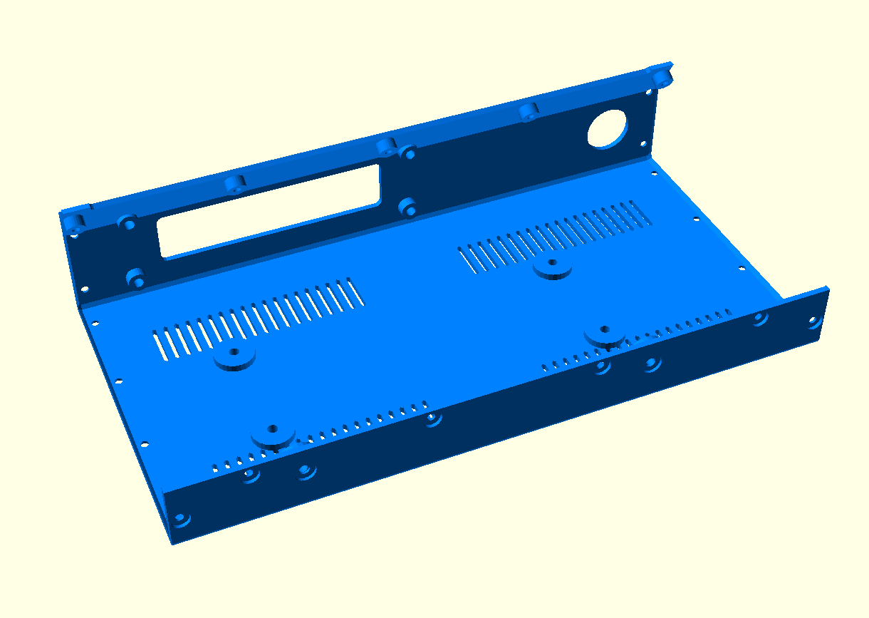
CDY BODEMPANEEL:

LEEG BODEMPANEEL: 

LINKER PANEEL:

RECHTER PANEEL:

VOORPANEEL:

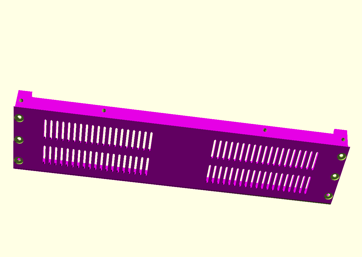
ACHTER/BOVEN PANEEL:

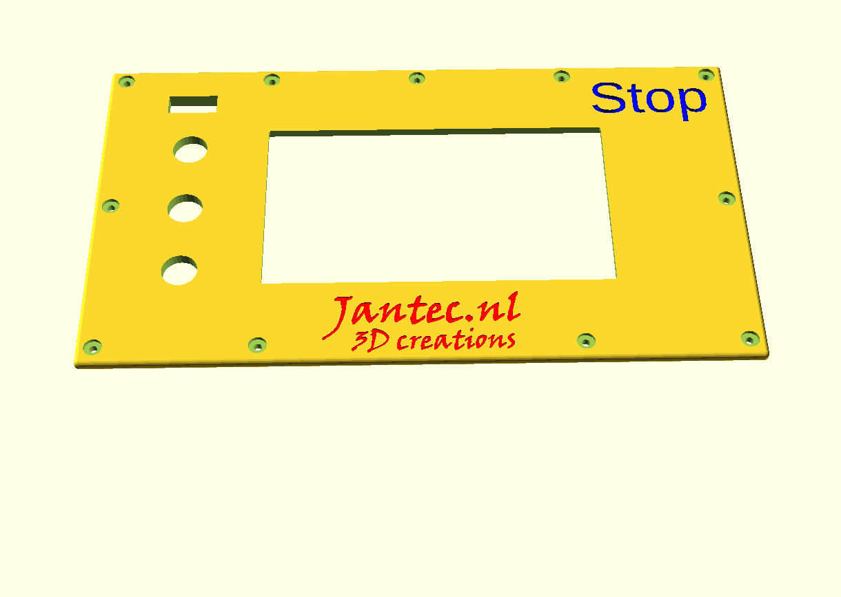
LCD PANEEL:

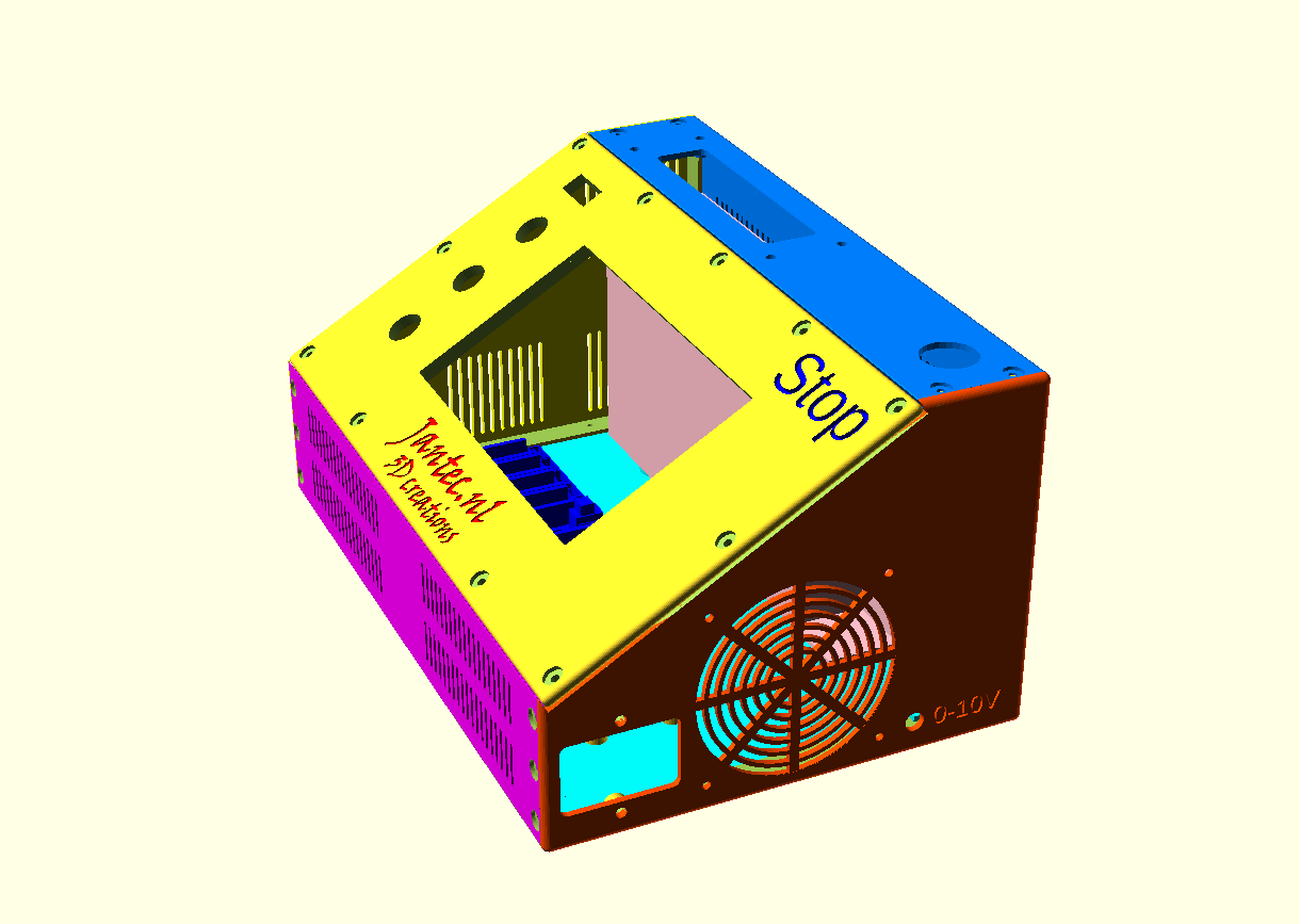
REAR TOP PANEL PART CNC FLYCDY CONTROLBOX BY JANTEC.NL


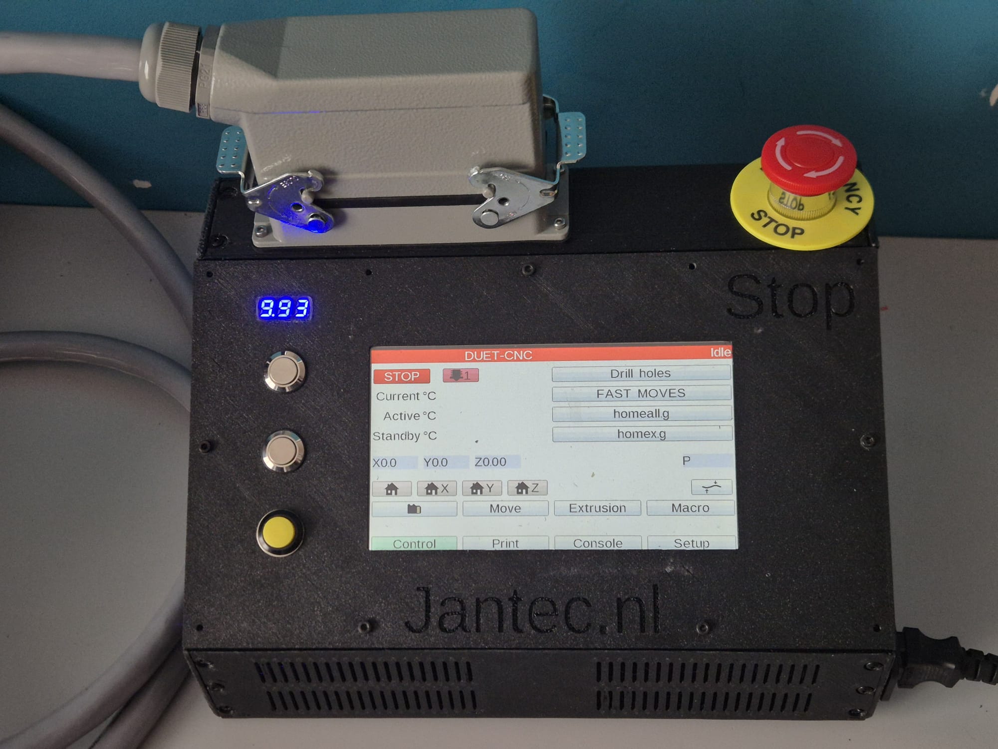
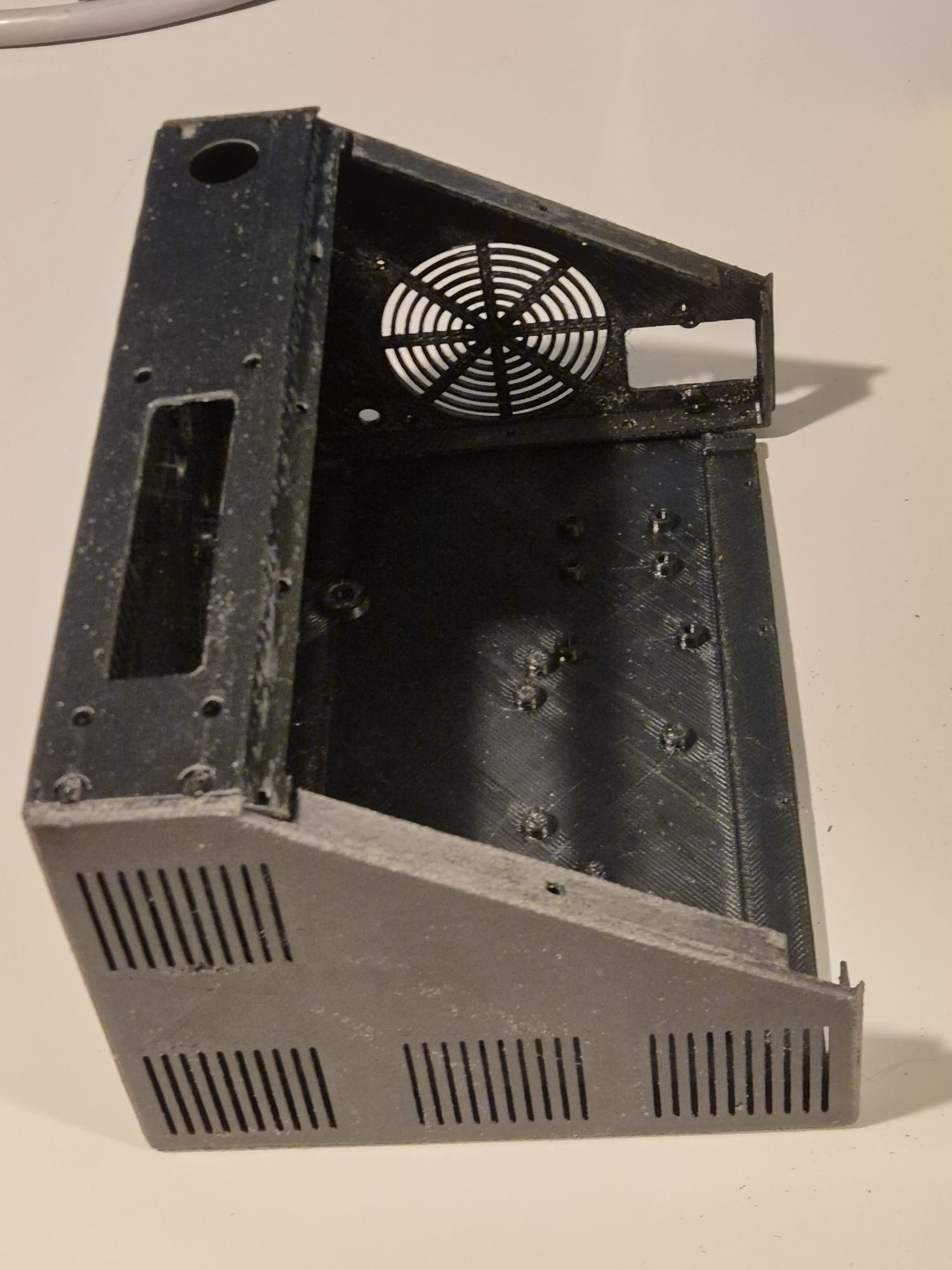
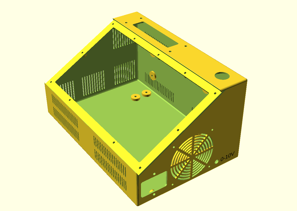
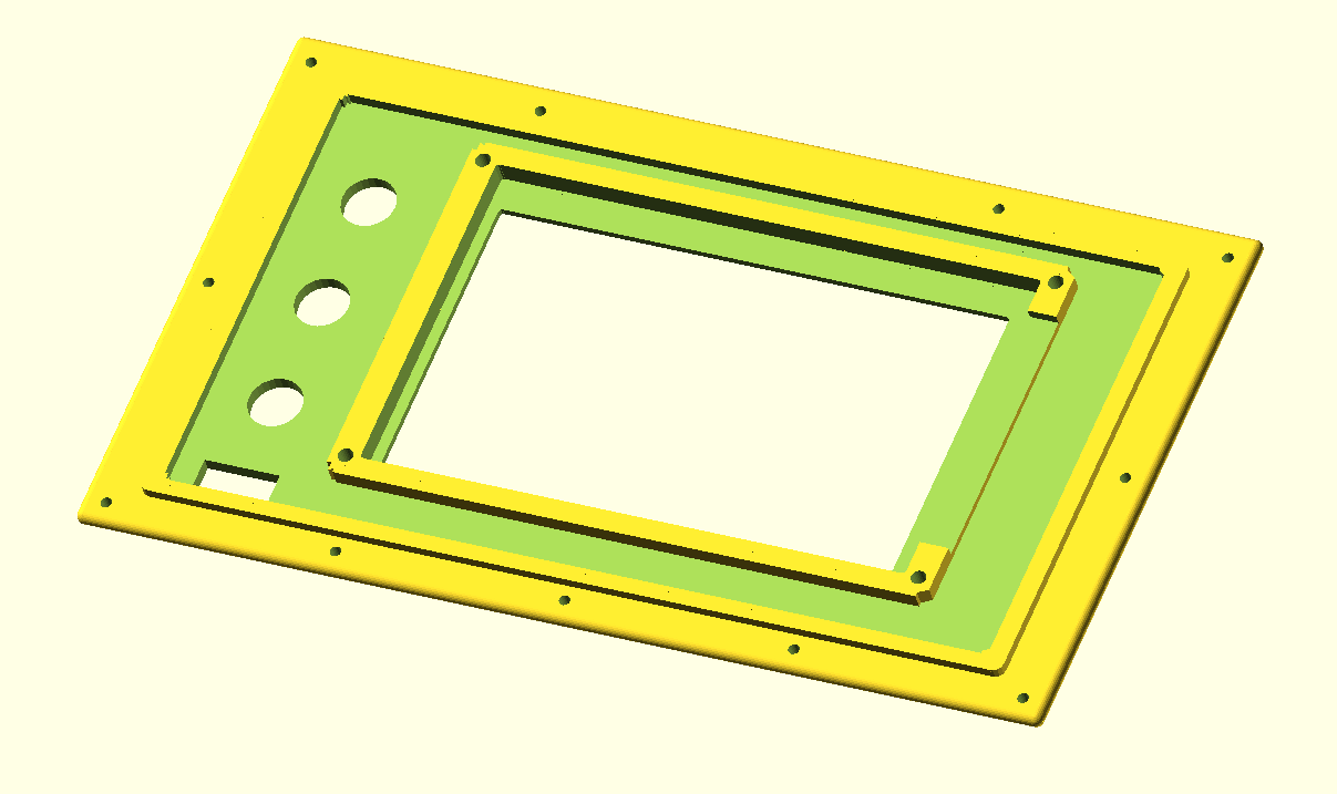
Het gekantelde LCD-bovenpaneel  bevat een FysetC Duepanel 7 inch LCD-module welke kan worden aangesloten op de FlyCDY2 of 3 (en natuurlijk ook op een standaard Duet 2- of 3 board ).

De box en het LCD-paneel bevatten ook:

  • gaten voor een forse 24-pins multiconnector aan de linker bovenkant,
  • een paniekknop aan de rechter bovenkant,
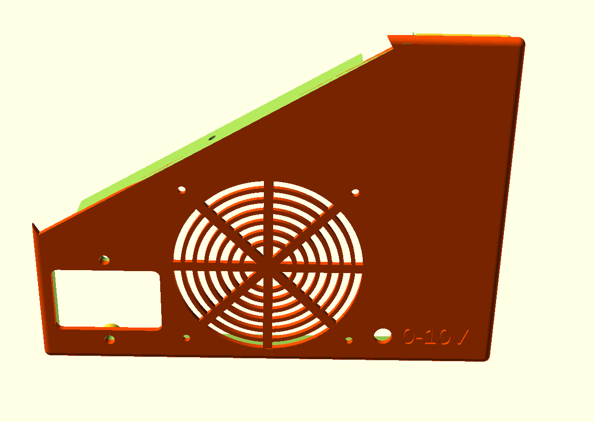
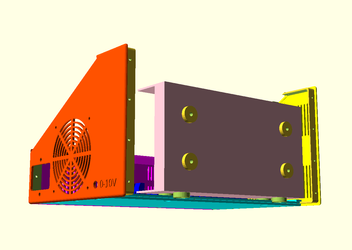
  • een 80mm ventilatoreenheid aan de zijkant,
  • een gefilterde voedingsingang (in mijn geval voor 230V Europa standaard)
  • een DC 0-10 Volt output bus rechts voor de aansluiting naar de spindle besturingskast voor de frequentiesturing,
  • 3 knopgaten op het gekantelde paneel,
  • een klein gat voor een spanning uitleesunit 0-10V voor de spindle

Eventuele andere benodigde gaten kunnen het beste na het printen worden aangebracht. Gewoon met normaal gereedschap, en eerst met schilderstape om de behuizing zo min mogelijk te beschadigen.

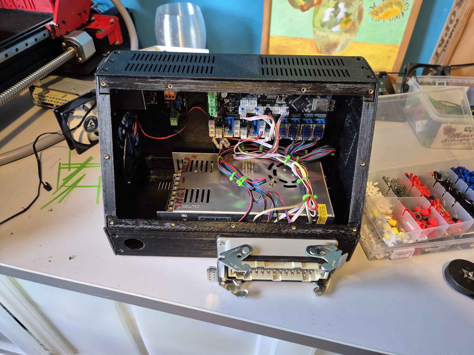
Alle onderdelen die erop of erin geschroefd worden, kunnen gebruik maken van M3 schroefdraadinserts op de montagepunten binnenin. De gaten ondersteunen deze.

Dit is niet gedaan voor de voedingseenheid (PSU), hier komen korte M4 schroeven door de behuizing in de PSU

De ventilator wordt gemonteerd met M3-schroeven van buitenaf door de behuizing en wordt vastgezet met moeren tegen het frame van de ventilator.

DOWNLOAD CNC_controller_box_6_parts_V2_C)JANTEC.NL_20251102

Doneer alsjeblieft $1 aan mijn paypal account als je (delen van) mijn ontwerpen gebruikt zodat ik dit kan blijven doen

HOE HET BEST TE PRINTEN

Ik print gereedschap en behuizingen altijd in ABS op 260-270 graden, 100% fan en 100% infill. Het voorpaneel heb ik ook geprint met 100% infill. Gebruik minimale support voor deze onderdelen, maar altijd maximale hechting! Ik heb ook ironing aan staan, zodat alles netjes past en er goed uitziet.

Stel Cura ook in op een krimpcorrectie van 100,7%, vanwege het feit dat de behuizing een krimp had van 2,2 mm aan de lange zijde. (De xSize moet 295mm zijn en gemeten bleek dit 292,9 mm te zijn na het printen.)

Om de behuizing te monteren met 6 afzonderlijk geprinte onderdelen, verbindt je eerst de bodemplaat aan de voorkant en achterkant en verbindt je daarna deze onderdelen met schroeven zonder lijm aan de zijkanten.

Schroef de delen met button head M3 schroeven van max. 8mm lang vast.

Waar nodig vijl of schuur je de pasdelen ietsje dunner zodat alles goed past.  Let op dat je de slicer instelt op ‘ironing, in ieder geval voor het voorpaneel en het achterpaneel zodat de pasvlakken goed worden geprint.

Je kan er voor kiezen alle delen extra stevig aan elkaar te verbinden door een klein beetje superglue in de naden te laten lopen.

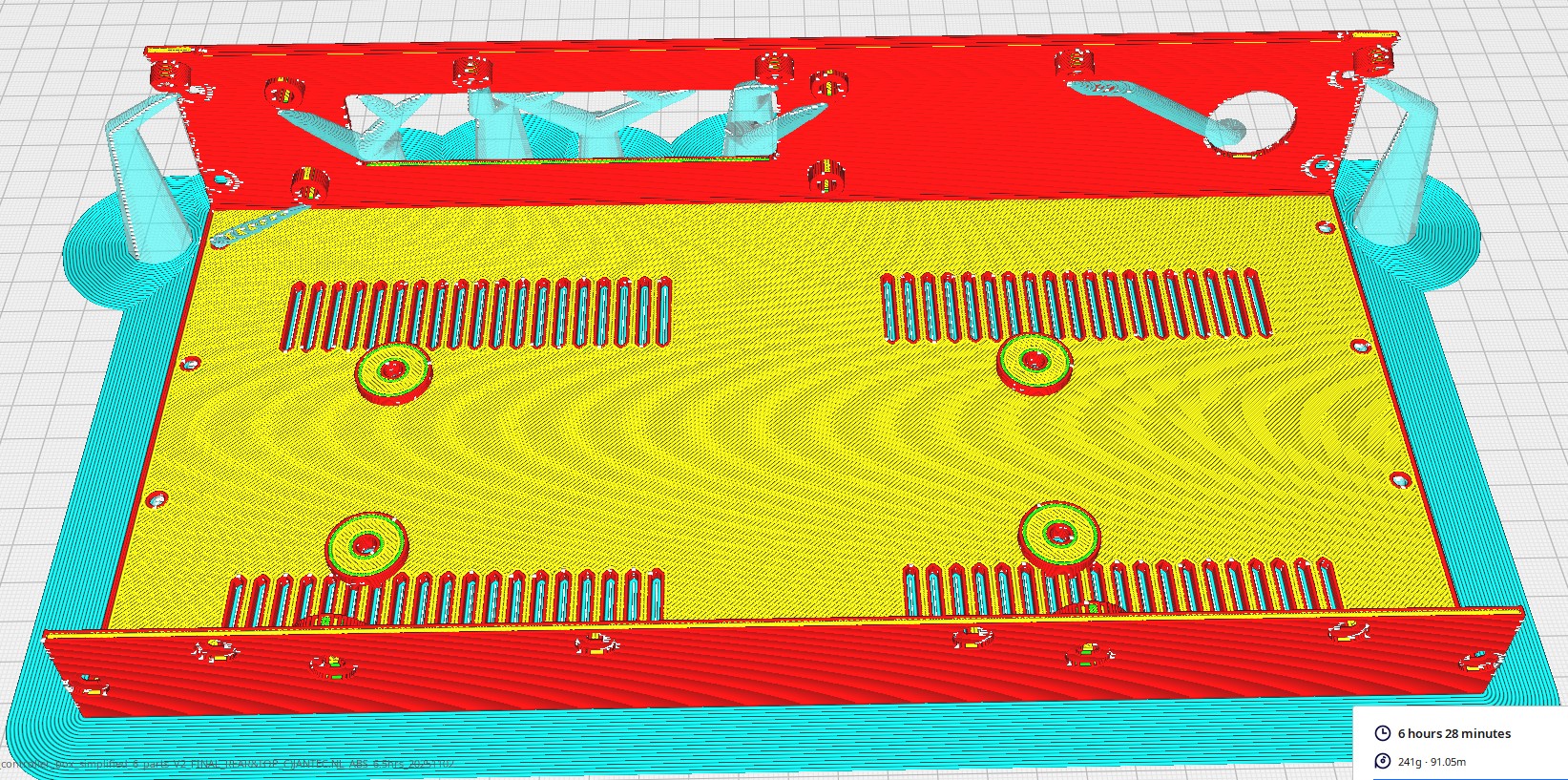
Let op dat je de alle delen print met de rasters naar beneden op de bodemplaat van de printer.

Alle onderdelen worden het beste geprint met 85% ondersteuning EN alleen hechting aan de buitenzijde van het object.

Printsupport in tree mode zet je aan op een hoek vanaf 85 graden zodat de M3-bus supports vanaf de onderkant goed worden ondersteund bij het printen.

PRINTORIËNTATIE VOORBEELD (Cura, VORON 2.4-600)

Houd er rekening mee dat het 6-delige ontwerp is ontwikkeld met het oog op 3d printen, dus in de afdrukstand zoals hierboven is getoond.

Dit is de enige manier om ‘overhang’ bij de in elkaar grijpende richels te voorkomen.

Dat gaat ook op ook voor het individueel printen van elk deel.

Succes!!

DOWNLOAD CNC_controller_box_6_parts_V2_C)JANTEC.NL_20251102

Doneer alsjeblieft $1 aan mijn paypal account als je (delen van) mijn ontwerpen gebruikt zodat ik dit kan blijven doen

VOORBEELDEN MET PLACEBO PSU en CDY board

box met placebo’s voor check op juiste positie en maatvoering

Voorbeeld eerdere release, box is hier geprint als 1 geheel


STL download 2-kleuren of standaard 1-kleur eierdop V26

COLOR1
COLOR2

Please donate $1 to my paypal account if you use my original designs !


gecombinerde kleuren voor mijn E3D toolchanger
Snel geprint op de E3D toolchanger met 0.3mm LH in PLA
Colors combined in 1 STL
     
Geprint op de originele Prusa mini+, in zwart ASA en met 0.2 mm LH (snel)

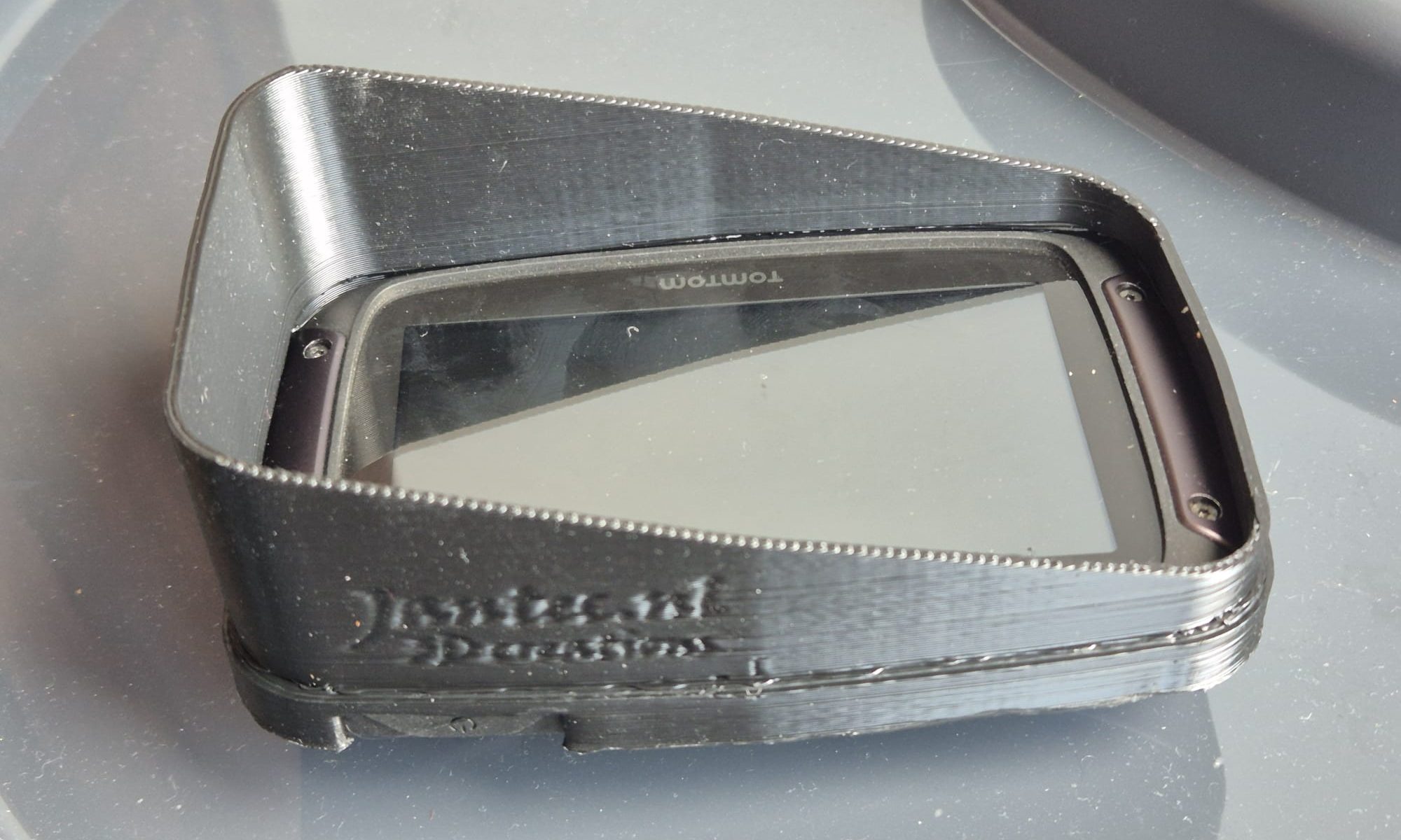
Download verticale zonnekap STL file voor Tomtom Rider 410-550

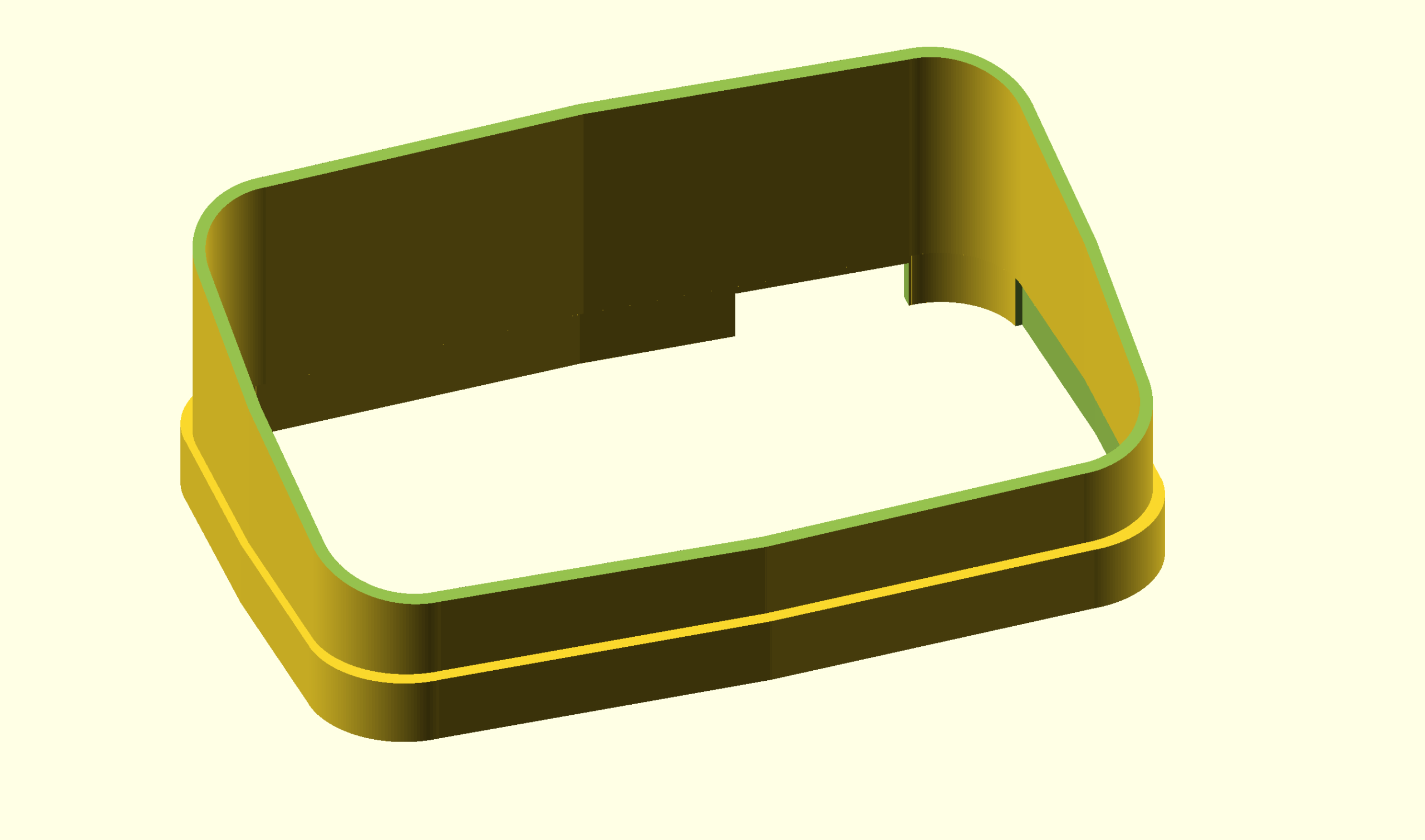
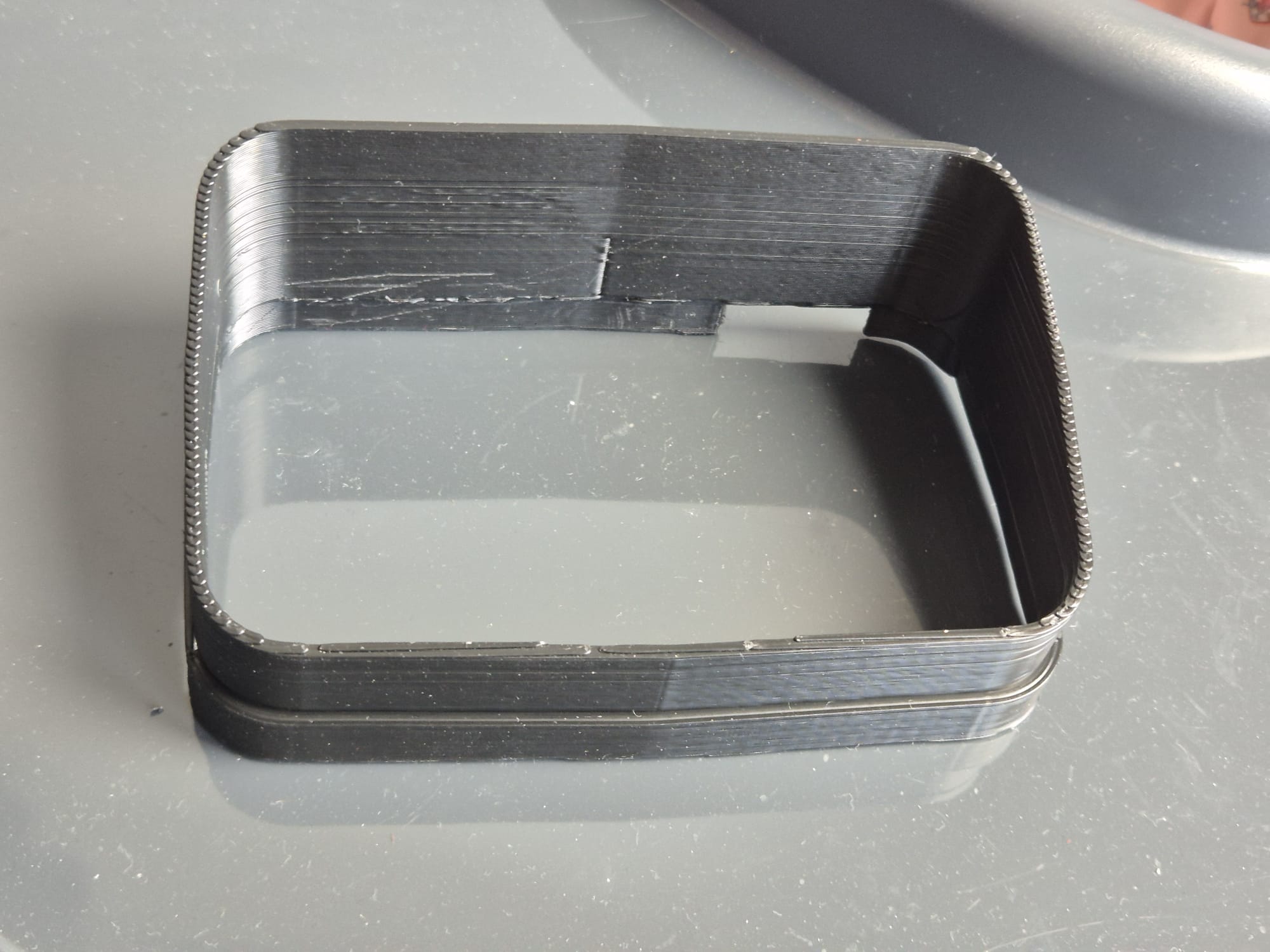
Ik heb dit ontworpen in Openscad en het kostte me 2 dagen (met tussenpozen) om het perfect te krijgen. Ik ben begonnen met een horizontale zonnekap die ik ooit een keer gedeeltelijk had ontworpen.

Please donate $1 to my paypal account if you use my original designs !

Tomtomrider550_sunshade_horizontal,_M_20251011V10

Maar ik wilde per sé een verticale kap maken omdat ik mijn tomtom rider altijd in die stand gebruik op mijn motorfiets.

Dus veranderde ik de horizontale zonnekap die ik eerder had gemaakt in een verticale, wat heel eenvoudig was toen ik de horizontale versie eenmaal perfect had. Het kostte me een paar pasbeurten voordat ik hem goed genoeg had.

Ik heb dit allemaal geprint op mijn Voron600, met zwart ABS op 275 graden, een nozzle van 0,8 mm en een laagdikte van 0,4 mm. Het duurde 32 minuten om de complete zonneklep voor mijn Tomtom Rider 550 te printen. Ik zet de object fan altijd op 60%, behalve voor de eerste 3 lagen en ik print op 120 mms behalve de eerste laag, die 20 mms is.

Ik gebruik een vrij hoge instelling voor de Z-hop-hoogte bij laagwisselingen, omdat dit specifieke ABS-filament bij deze temperatuur een kleine blob kan geven aan het einde van de printlijnen en ik niet wil dat de nozzle hierin vastloopt bij laagwisselingen. Ik wil ook niet meer dan 0,2 mm retracten, omdat ik niet wil dat er filament vast komt te zitten in mijn cold-end.

De zonnekap past goed om de Rider 550, maar als je vindt dat hij niet strak genoeg zit, print de zonnekap dan op 99 % voor de X- en Y-vermenigvuldigingsfactoren van je slicer.

En ja, je zou dit STL-bestand op elke 3D-printer met elk filament moeten kunnen afdrukken en je eigen voorkeursinstellingen voor de printer moeten kunnen gebruiken.

Je krijgt veel mooiere afdrukken als je een 0,4-nozzle in je hotend gebruikt en deze instelt op een laagdikte van 0,2 mm. Het afdrukken duurt dan ongeveer 2 +- uur. Veel succes!

Please donate $1 to my paypal account if you use my original designs !

UPDATED (nightly version)

Tomtomrider550_sunshade_vertical_L_20251011V10


Tomtomrider550_sunshade_vertical_XL_20251011V10

ABS beste snelheid- , ventilator- en temperatuur 3dprint instellingen

STANDAARD ABS start instellingen

Nozzle: 265 °C,   Bed: 110 °C

Objectventilator: 25% max vanaf 5e laag, daaronder 0%

MIJN GEBRUIK VAN ABS

Ik gebruik bijna uitsluitend ABS voor mijn professionele prints met een 0,6 of 0,8 nozzle.
Dat komt omdat het goedkoop is, zeer stevige prints oplevert en bestand is tegen vrij hoge temperaturen.
Ik gebruik ABS voornamelijk voor auto-interieuronderdelen, tuinartikelen enzovoort.
Voor alles wat in contact komt met voedsel, kinderen enzovoort gebruik ik PETG.

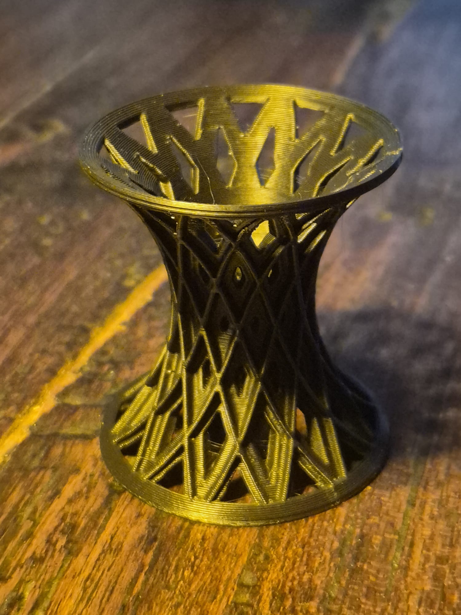
PETG transparant testprint

Voor alle andere prints en alle meerkleurige prints gebruik ik PLA.
Omdat ik voor elk type filament een speciale printer gebruik, heb ik bijna nooit last van verstoppingen of mislukte prints.

ABS – mijn ervaringen

Er is eigenlijk geen standaard voor ABS-instellingen. Dat komt doordat niet alle ABS op de markt echt van hetzelfde type is.

Ik kan wel enkele tips geven voor verschillende soorten ABS-filament van 1,75 mm, op basis van mijn ervaring met die specifieke soorten filament.

AANBEVELING: PRINT MIJN TESTOBJECT VOORDAT JE EEN OBJECT PRINT en controleer de rand, de stevigheid van de wandhechting en de laaghechting.

Gewoon ABS: nozzletemperatuur 270 °C (15 °C te laag), bed 120 °C, objectventilator 30% (moet 0% zijn), 0,8 nozzle bij 0,4 mm laagdikte, printsnelheid ingesteld op 120 mm/s, overal GROTE BRIM, brim ook bij LH 0,4 mm, lijnbreedte precies ingesteld op 0,8, alles gesneden in Cura

DOWNLOAD JANTEC.NL’s TESTPRINT_tilted_raster_20250902V1_STL

Als de print uit elkaar valt wanneer u deze met weinig kracht probeert te breken, zoals op de bovenstaande afbeelding, is de printtemperatuur te laag. Hetzelfde geldt voor de vleugels van het teststuk als voor de hechting van de lagen.

Als u een bubbelachtig oppervlak ziet, is uw ABS nat. Het zal waarschijnlijk niet meer te redden zijn. U kunt proberen het te drogen in een oven of in een voedseldehydrator bij 80 °C, gedurende ten minste 10 uur. Mijn ervaring is dat dit een verspilling van tijd en energie is. Gooi het gewoon weg in de plastic recyclingbak.

ALGEMENE ABS-OMGEVINGSVOORWAARDEN

Voor alle ABS-materialen heb je een hotbed nodig van minimaal 90 °C, maar 120 °C is beter;

U hebt ook een hotbed topplaat nodig met een laag glad PEI erop, OF een hotbed topplaat met gestructureerd PEI, die ik vooral gebruik voor mijn prints met een spuitmond van 0,8 mm;

Gebruik in het algemeen nooit een toolfan. Tenzij u ABS met een lage temperatuur gebruikt, zoals EASY ABS, met de vereiste lagere bed- en spuitmondtemperatuurinstellingen;

Gebruik altijd een volledig afsluitende behuizing voor je printer;

Maak altijd een bedmesh dat echt werkt voordat u ABS afdrukt en zorg ervoor dat dit wordt gedaan bij bedrijfstemperaturen van zowel het bed als de spuitmond;

Print overal met een echt grote rand (BRIM) om het te printen object, minimaal 10 lijnen breed, ook voor uw ondersteuningsstructuur;

Print de eerste laag met minimaal uw normale printtemperatuur, NOOIT lager;

GEEN objectventilator op de eerste 4 lagen!

SUNLU ABS (WIT EN ZWART)

Sunlu heeft ABS-filament dat glanzend is op de spoel en bij de juiste temperatuur glanzend kan worden geprint. Dit filament is niet erg gevoelig voor kromtrekken. Het is mijn favoriete versie ABS.

Slagvast en zonder problemen in de zak houdbaar, vrijwel ongevoelig voor vocht.

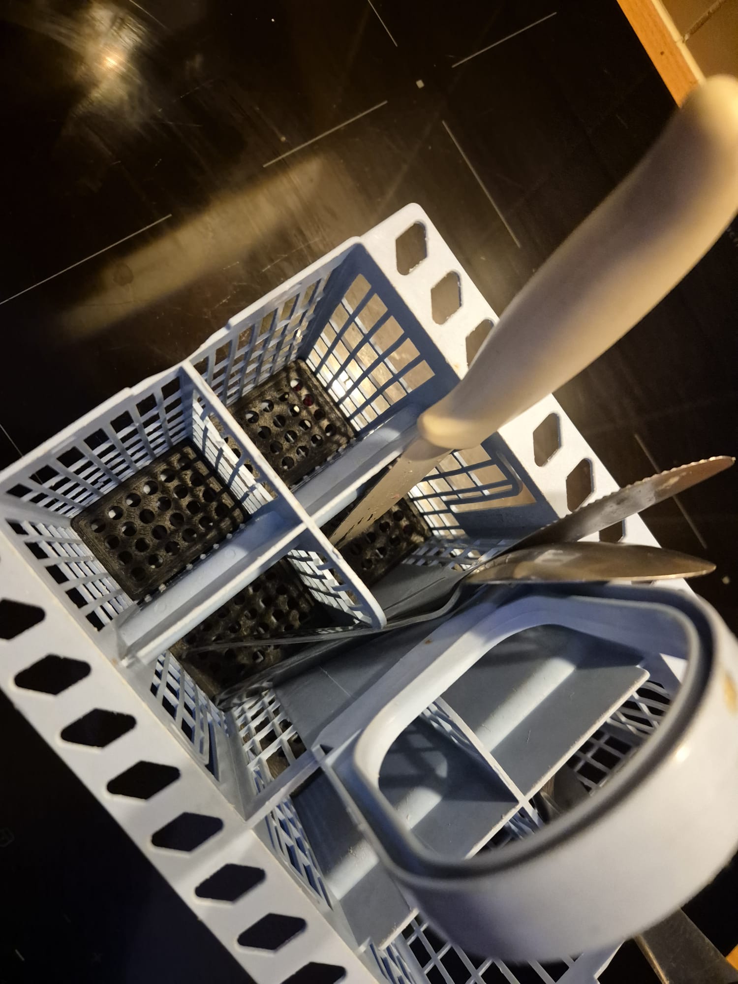
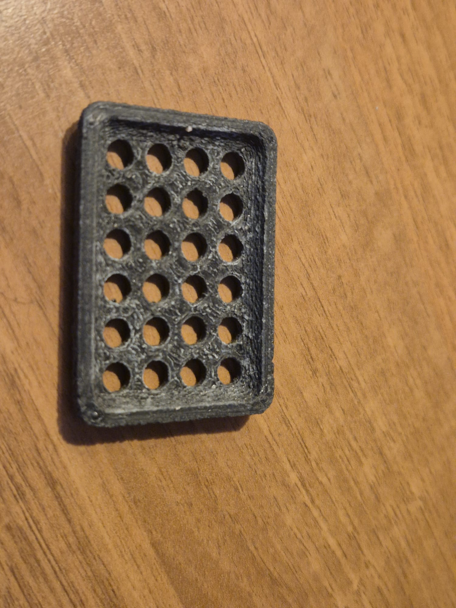
Ik heb hiermee vulplaatjes gemaakt voor mijn kapotte onderkant van de bestekbak van de Indesit vaatwasser, dat gaat al jaren mee zonder problemen:

click on the picture to download my original STL file

Nozzle: 265 °C-280 °C

Bed: 120 °C

Objectventilator: 30% -50% max = normaal, geen objectventilator op de eerste 4 lagen

Sunlu black abs @275 deg, 50% fan, Voron 600 bed 120deg, 0.8 nozzle at 0.75LW _0.4LH 20251105
bed adhesion Sunlu black abs @275 deg, 50% fan, Voron 600 bed 120deg, 0.8 nozzle at 0.75LW _0.4LH 20251105

EASY ABS (ROOD)

Dit ABS is ook glanzend, zorgt voor zeer stevige prints en heeft een lagere temperatuur nodig dan algemeen ABS. En het vereist een behoorlijk beetje objectventilatorsnelheid. De prints komen glanzend uit de printer. Voor zover ik heb ervaren, is dit type ABS helemaal niet gevoelig voor kromtrekken.

MAAR- dit is het enige type ABS of ASA dat ik ben tegenkomen tot nu toe, dat NIET tegen de vaatwasser kan.  Het komt er flexibel uit, als je na het ‘gereed’ piepje de vaatwasser opent.

Nozzle: 235 °C -245 °C

Bed: 70 °C -90 °C

Objectventilator: 60% -100% max = normaal, geen objectventilator op de eerste 2 lagen

MICROZEY RED ABS

Microzey ABS, 285deg nozzle, 130 deg bed, no fan. Printed on Voron 300, 0.8 nozzle, 0.75Layer Width and 0.4Layer Height

GENERIEK ABS (ROOD, mat)

Dit is het moeilijkst te printen matte rode ABS (op de spoel) en vereist een zeer hoge printtemperatuur. Het kan geen enkel percentage objectventilator aan. De prints komen er mat uit wanneer ze onder 270 graden worden geprint en bij 285 graden zijn ze glanzend. Dit type ABS is zeer gevoelig voor kromtrekken. Dit is waarschijnlijk een type ABS zonder toevoegingen.

Nozzle: 285 °C

Bed: 120 °C

Objectventilator: 0% max=normaal, geen objectventilator op de eerste 4 lagen

Supersterke print met dit filament en bovenstaande settings!

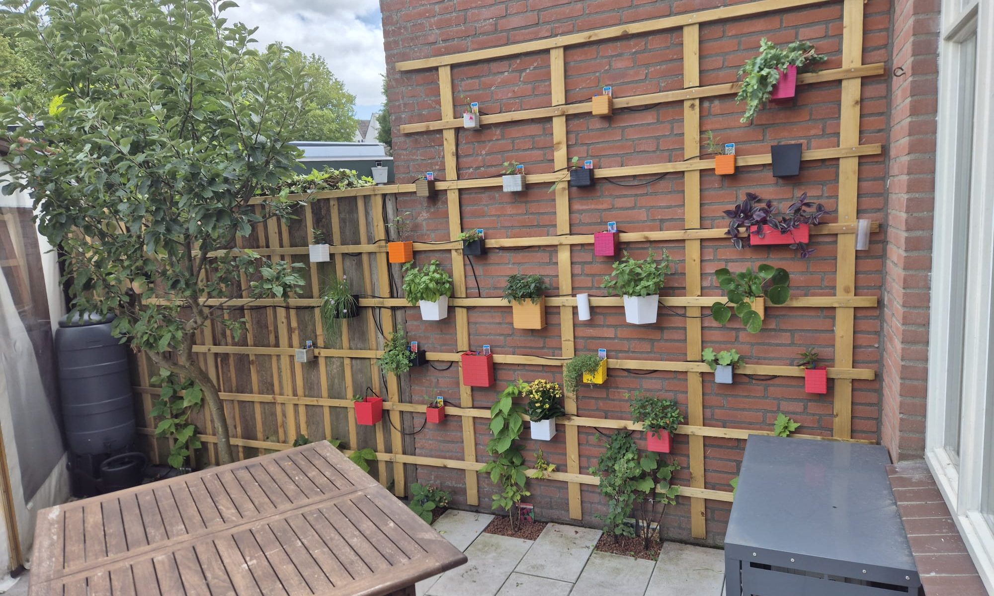
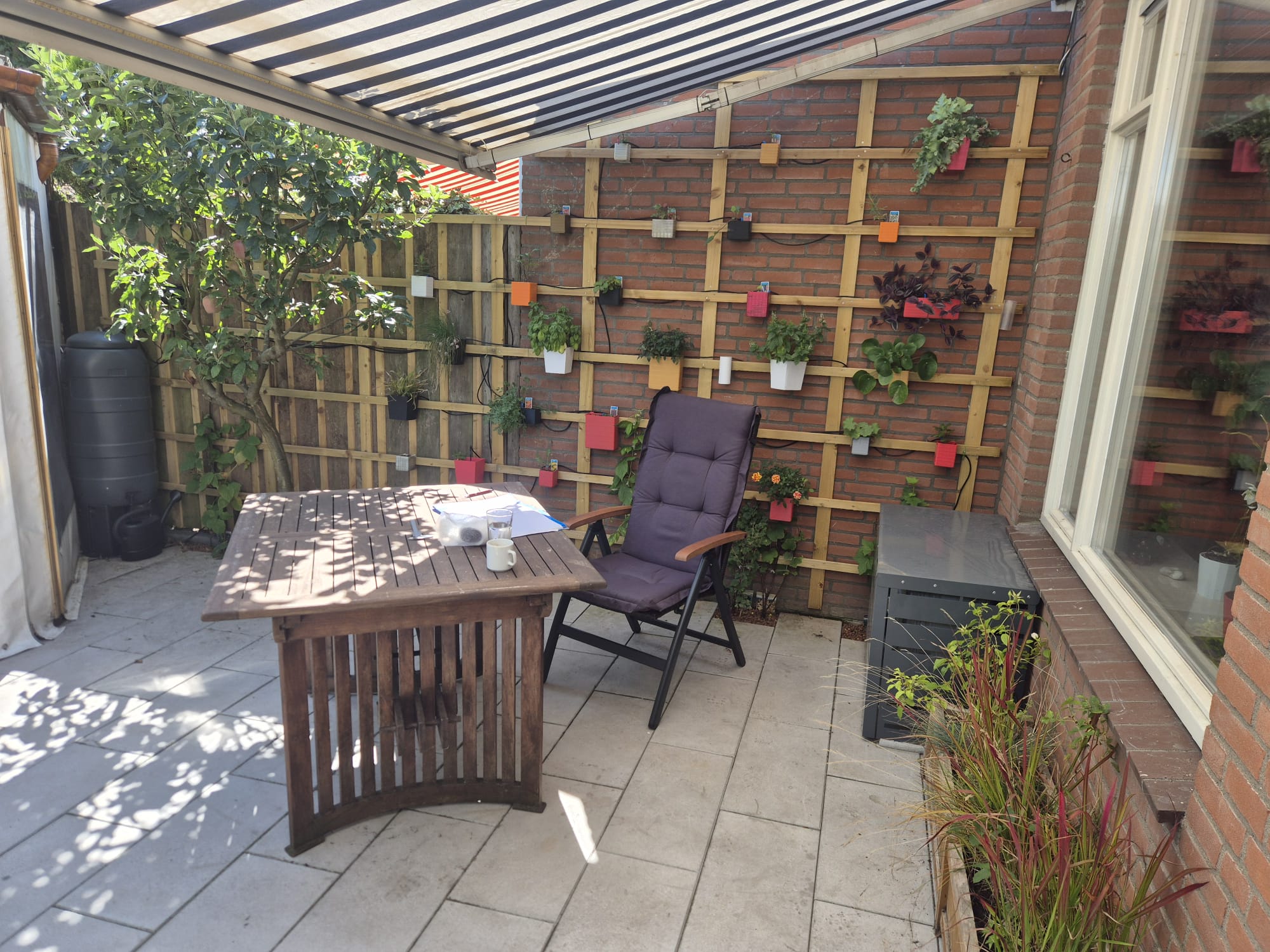
Tuinmuur met 3D-geprinte hangende bloempotten – download gratis STL-bestanden

In mijn kleine tuin staat een muur van de aanbouw van mijn buurman naar mijn gevoel altijd nogal  zichtbaar in de weg. Ik heb lang nagedacht over hoe ik deze muur wat aantrekkelijker kon maken terwijl ik in mijn tuin zit, en kwam tot het volgende idee:

Ik heb een opstelling gemaakt met geïmpregneerde houten tuinplanken, die ik in de lengte heb gezaagd met mijn kleine draagbare zaagmachine. Het hout draagt ongeveer 30 kleine 3D-geprinte bloempotten in allerlei kleuren en vormen.

In de bloempotten heb ik verschillende kleine plantjes gezet waarvan de meeste de Nederlandse winter kunnen doorstaan, zodat ik de planten volgend jaar niet allemaal hoef te vervangen.

Daarnaast heb ik een automatisch bewateringssysteem op zonne-energie geïnstalleerd dat gebruikmaakt van de 2 kleine regentonnen.

Ik ben erg blij met het resultaat!

Hieronder heb ik mijn bloempotontwerpen voor deze muur verzameld.

Als je op de link klikt, wordt het STL-bestand automatisch naar je apparaat gedownload.

Succes! Jan, 08-2025


square_plant_hanger_b100xd100xh110_V12_REVd_20250702 square_plant_hanger_b220xd80xh80_V12_REVd_20250701 square_plant_hanger_b80xd80xh100_V12_REVc_20250701 Diagonal_plant_hanger_T110_B90_H125_V2_20250701 Square_diagonally_placed_plant_hanger_TOP110_BOTT90_HEIGHT225_V1_20250630 Facets_semi_round_plant_hanger_TOP260_BOTT170_HEIGHT220_V15_20250628c


Doneer alsjeblieft $1 aan mijn paypal account als je (delen van) mijn ontwikkelde materialen gebruikt zodat ik leuke dingen kan blijven delen

GRATIS STL-DOWNLOADS verloopstukken, bochten, verzetstukken, montagebeugel en wanddoorvoeren voor 55×110 mm luchtkanaalbuis

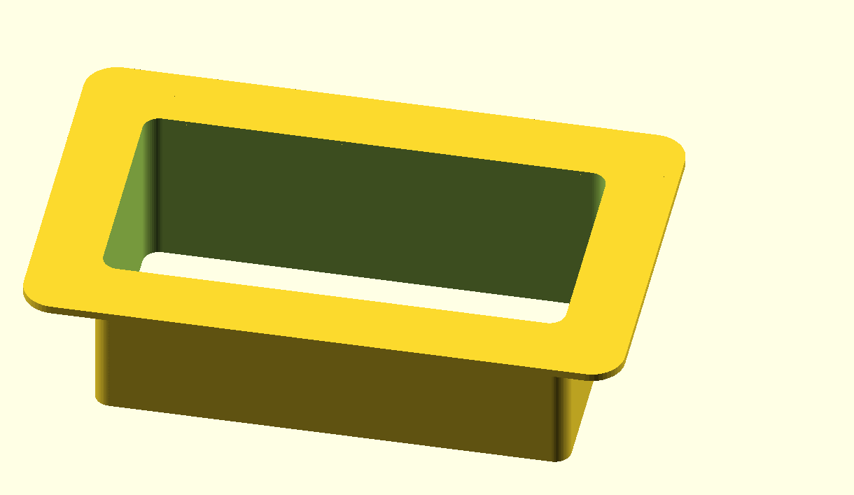
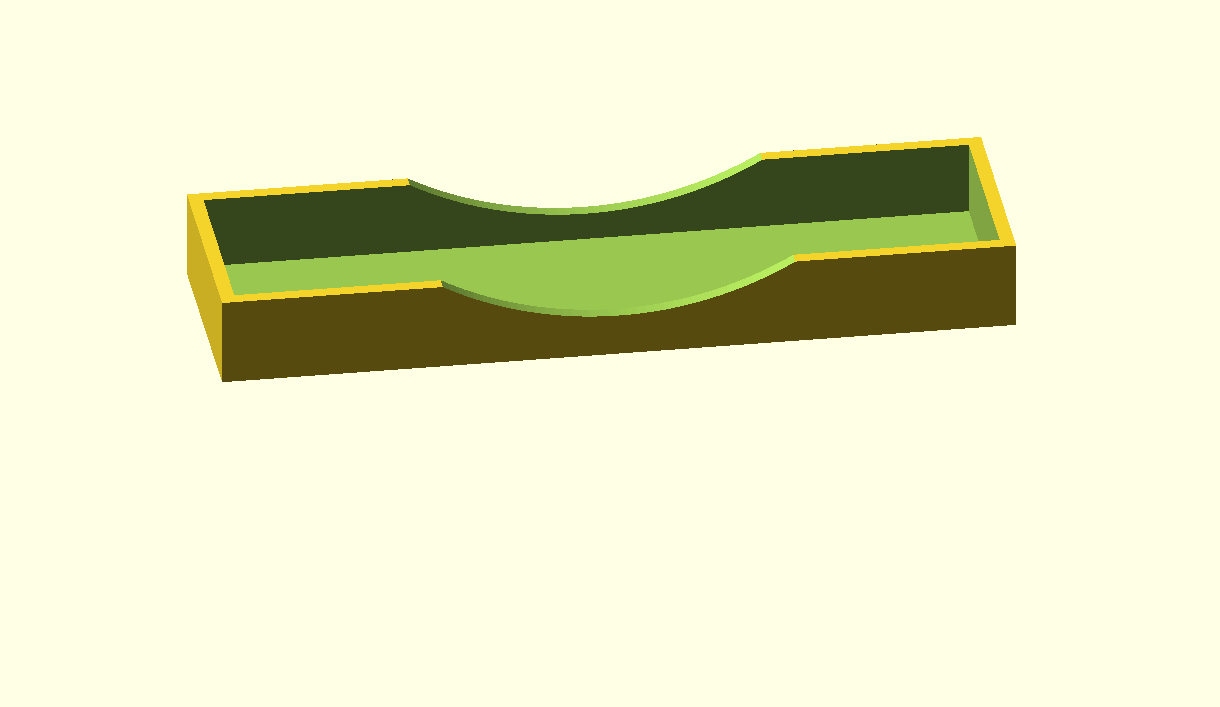
10mm wall plate for 55x110mm air duct. The wall plates are glued in place in the wall and are also used for  covering the sides of the through-hole in the wall. The 55×110 air duct will then pass through the glued-in wall plates on either side of the wall.

40mm wall plate for 55x110mm air duct.
wall_plate, extended to 60mm for 55x110mm air duct. This piece connects through the wall  and fits in one of the above wall plate-pieces
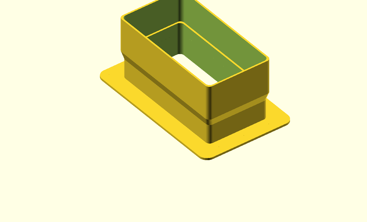
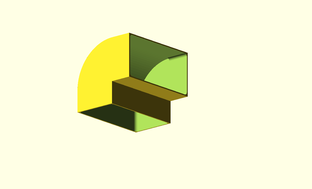
wall plate with short 90 degrees angled bend. Both sides connect to a 55x110mm air duct


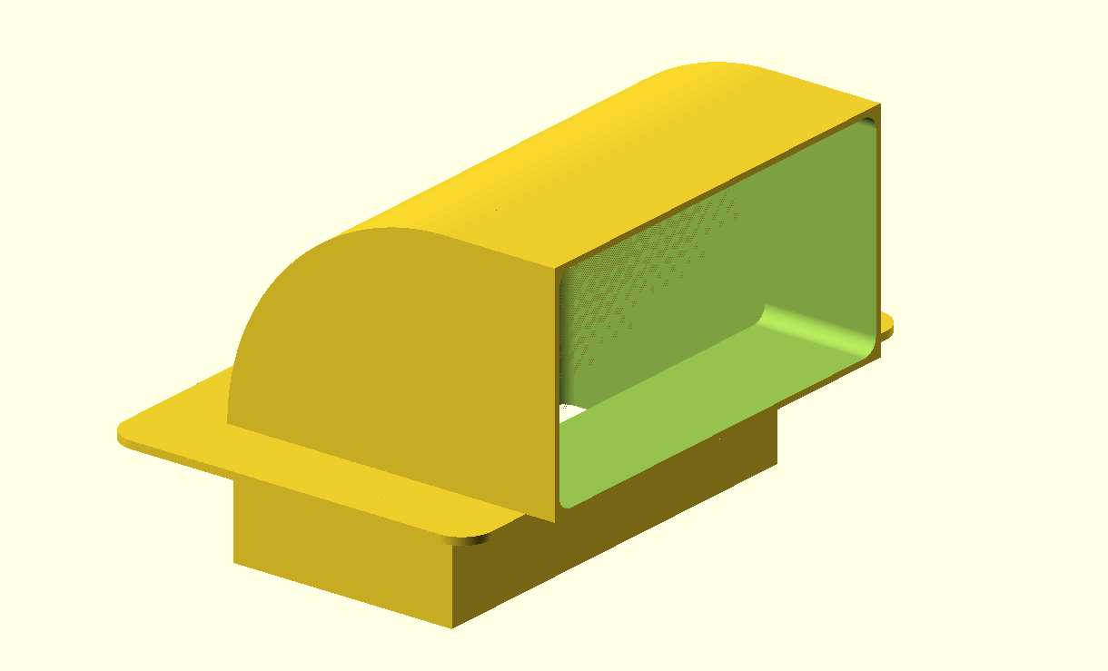
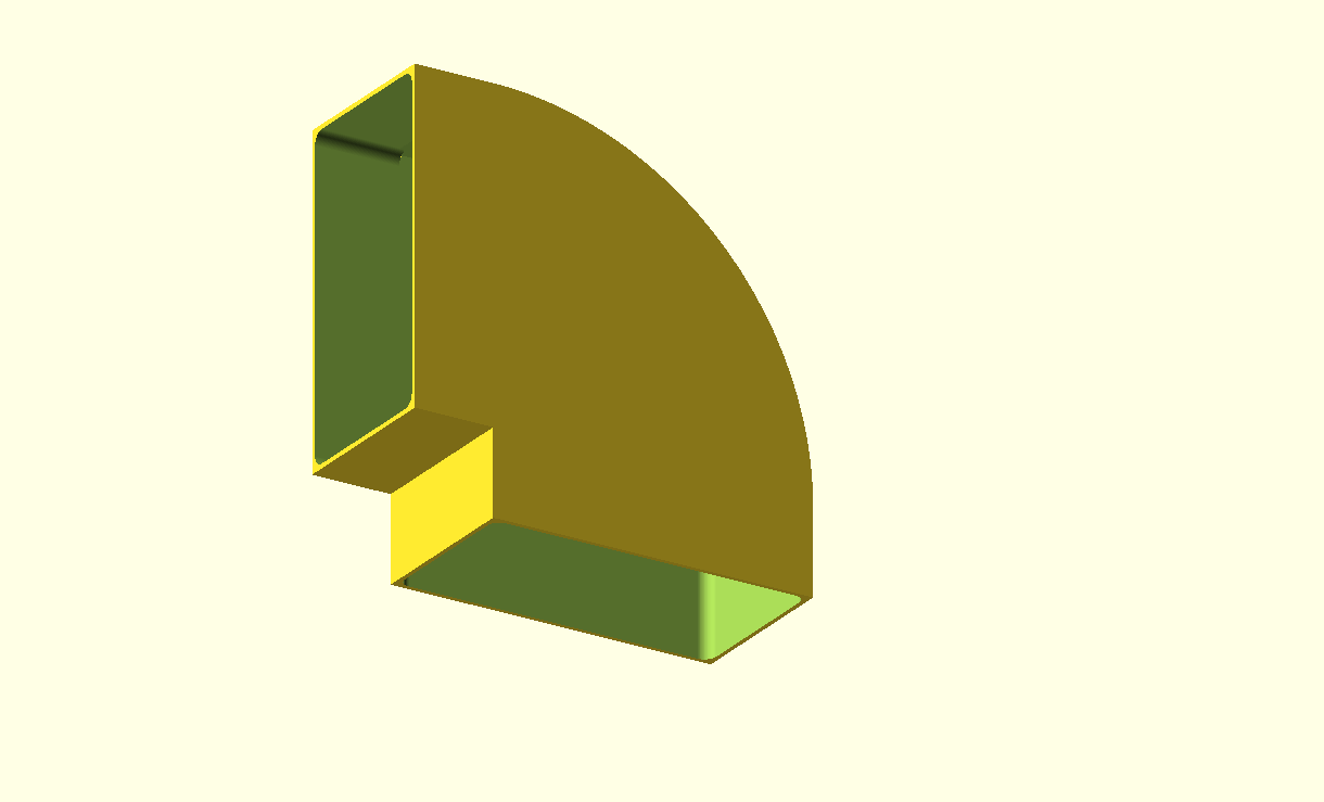
90 degrees bend for 55x110mm air duct
90 degrees bend for 110x55mm air duct
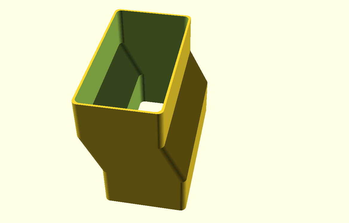
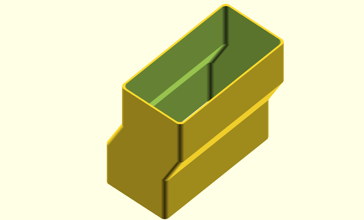
pipe connector piece with 15mm offset, both sides connect to a 55x110mm air duct
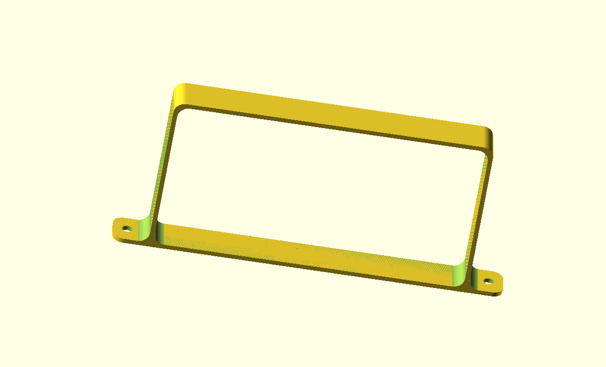
slim mounting bracket for 55x110mm air ducts


transition piece from round 150mm air filter box output to 55x110mm air duct, wall_mounted
endcap for 55x110mm air duct


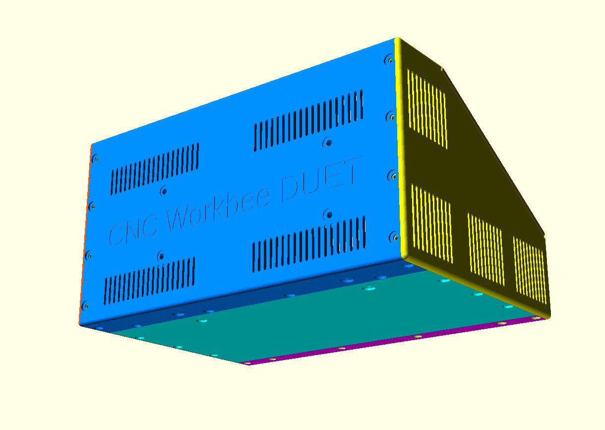
CNC workbee besturingskast gratis OBJ download met plek voor DUET3, voeding, paniekknop, 24pens multiconnector en Fysetc 7 inch Duepanel touch-LCD

Omdat het DUET3 besturingsboard qua formaat niet in de eerder ontwikkelde CNC behuizing voor een FLY_CDY board  past moest er veel worden aangepast.

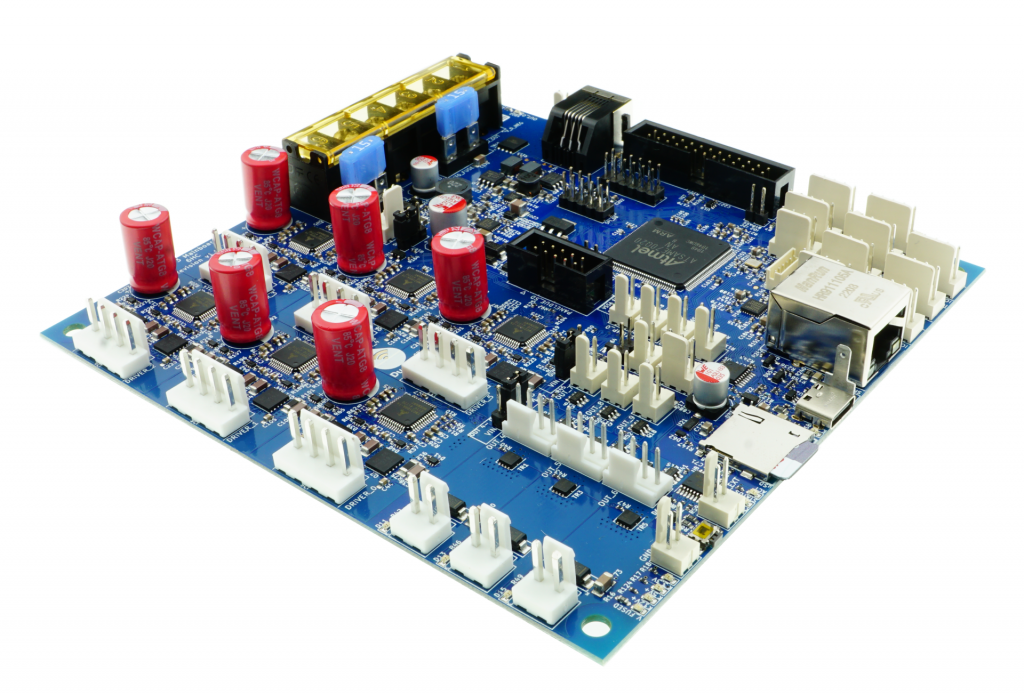
DUET3 motherboard

De box en het frontpaneel voor DUET3 is als voorlopig (V13) OBJ ontwerp HIER beschikbaar.

Doneer alsjeblieft $1 aan mijn paypal account als je (delen van) mijn ontwerpen gebruikt zodat ik dit kan blijven doen

Verdere ontwikkeling loopt nog op deze CNC behuizing voor DUET3.


TOP aanzicht van de CNC workbee DUET3 behuizing, met de uitsparingen en bevestigingspunten voor de threaded inserts zichtbaar links boven
Zij- aanzicht van de CNC workbee DUET3 behuizing, met de uitsparingen voor de reset, microsdCard, USB en Ethernet aansluiting zichtbaar onder, links van het midden. De canbus aansluiting zie je aan de voorkant van de behuizing, onderaan.


TOP aanzicht van de CNC workbee DUET3 behuizing, met de uitsparingen en bevestigingspunten voor de threaded inserts zichtbaar links boven

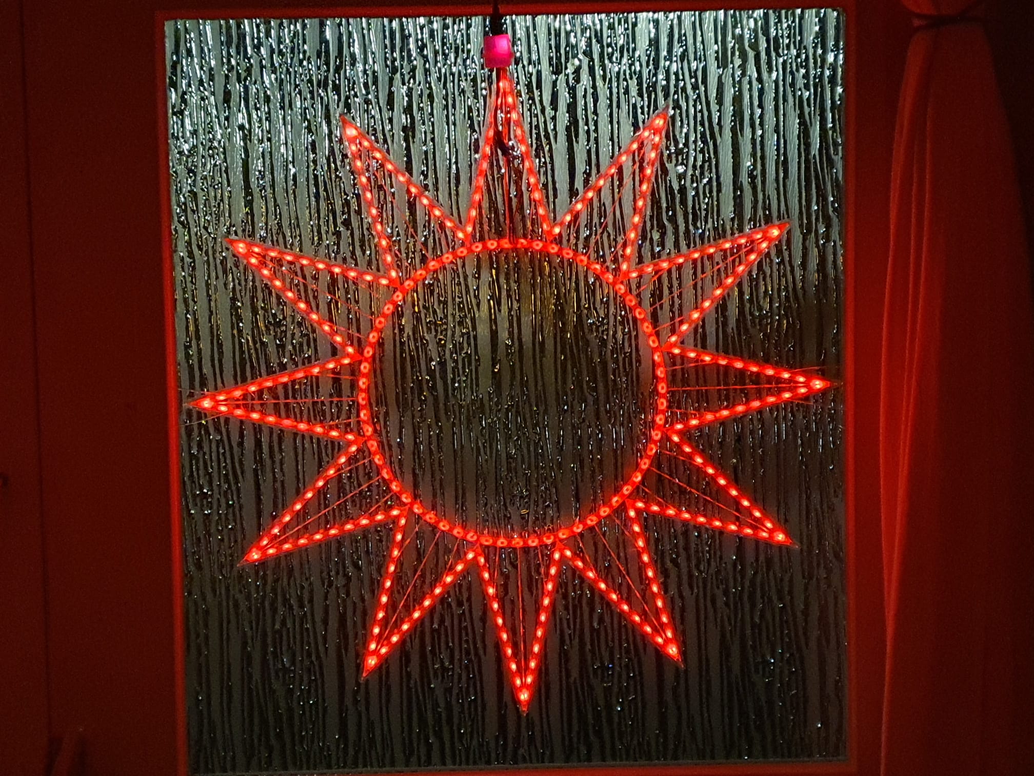
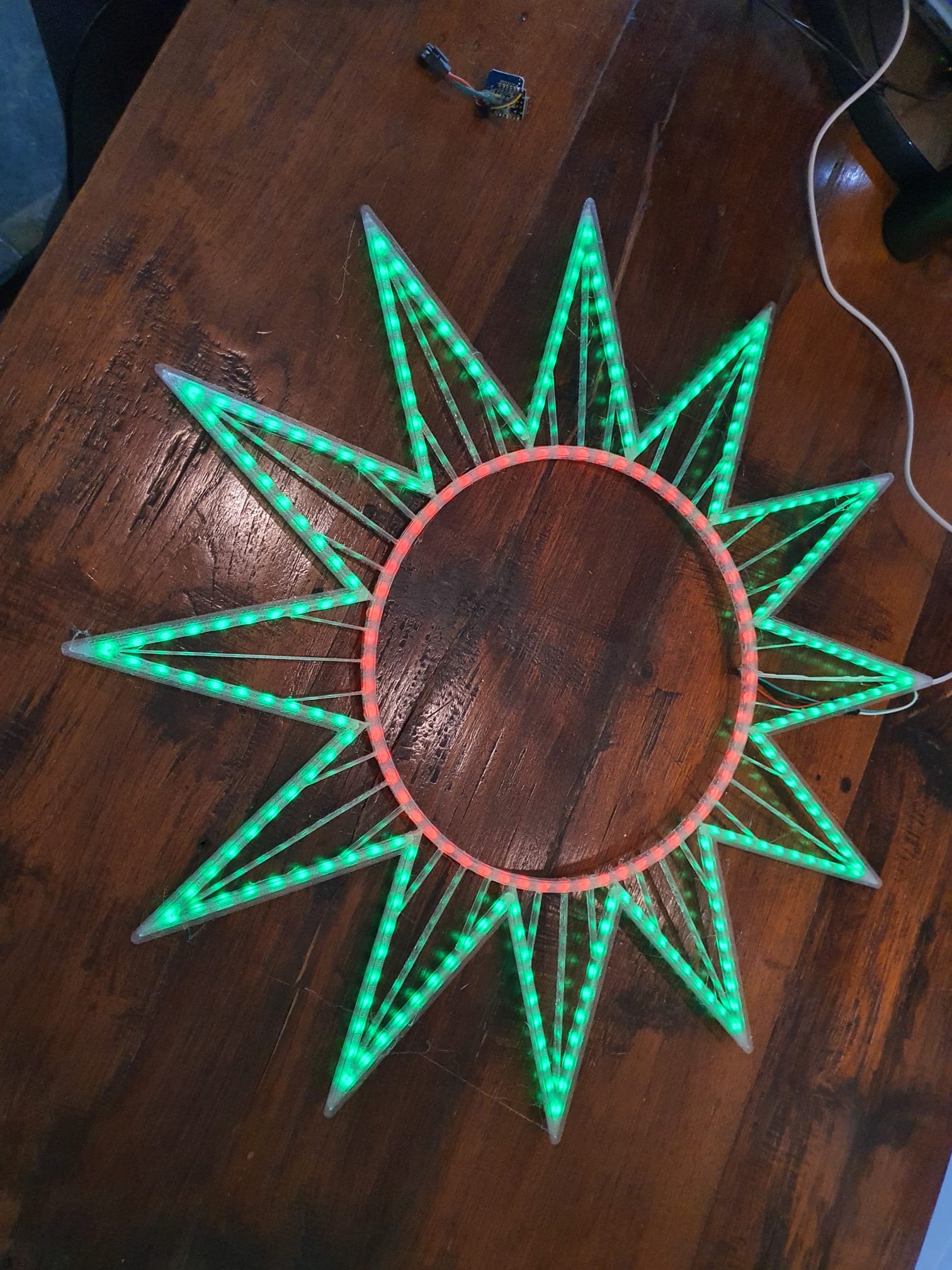
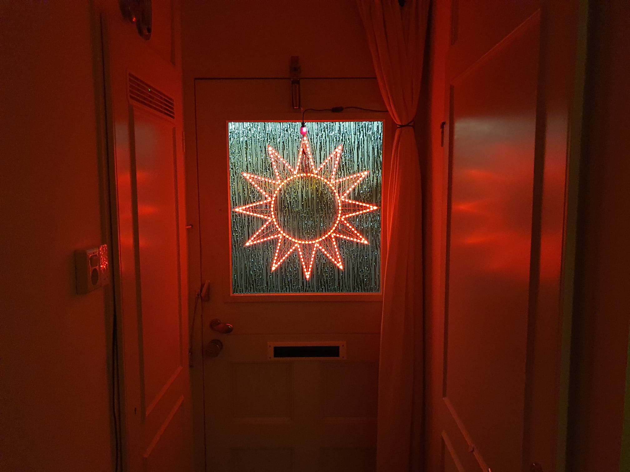
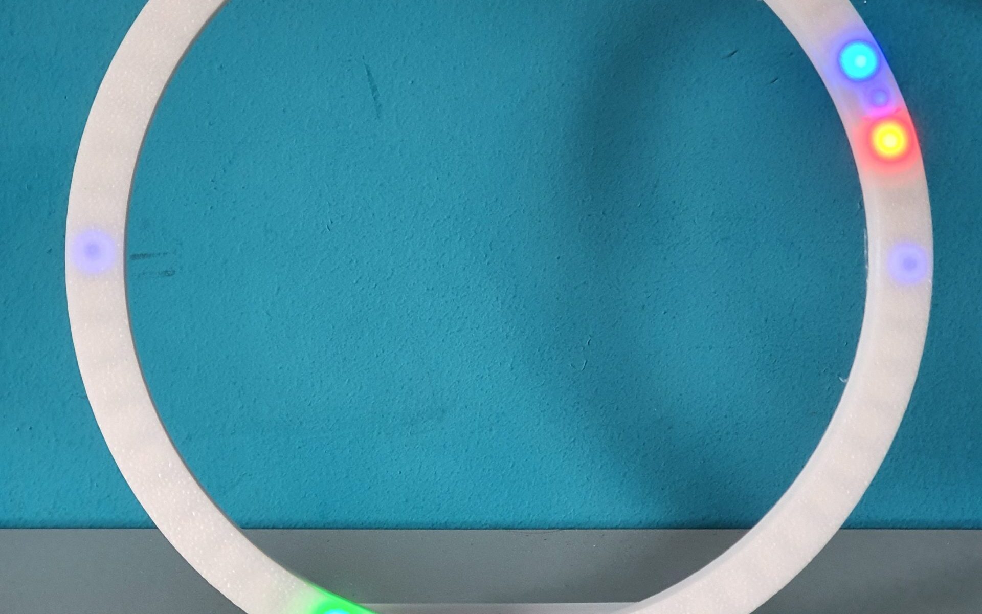
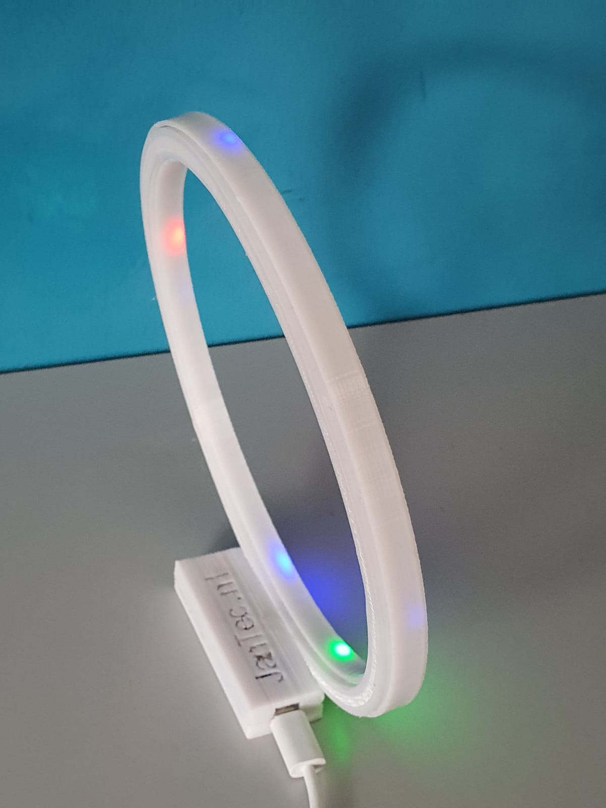
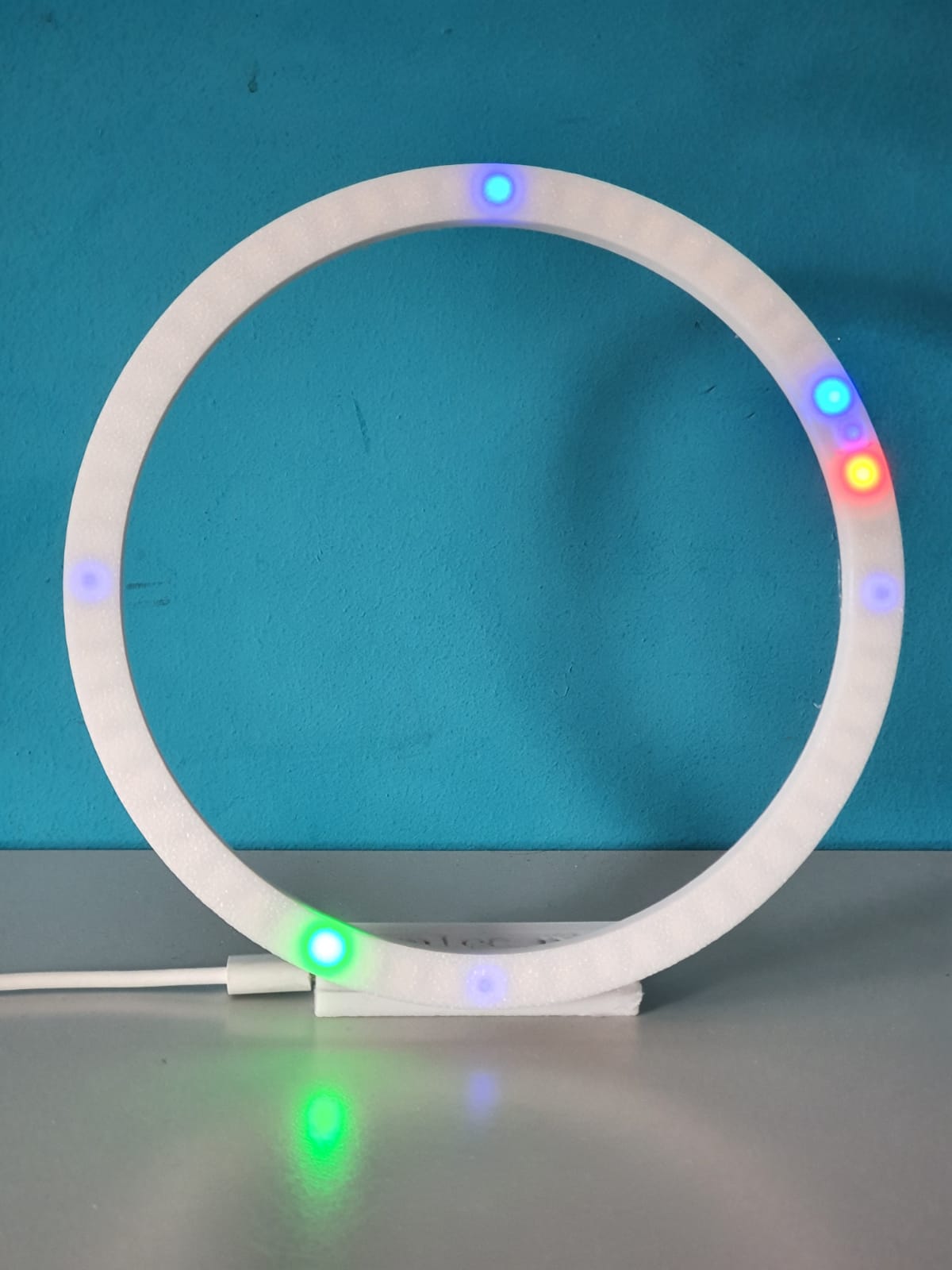
printbaar STL ontwerp 60 of 30 cm verlichte kerst zonnebloem met 300, 240 of 180 WS2811 RGB LEDS

Deze week een nieuw ontwerp gemaakt voor onze kerstverlichting!

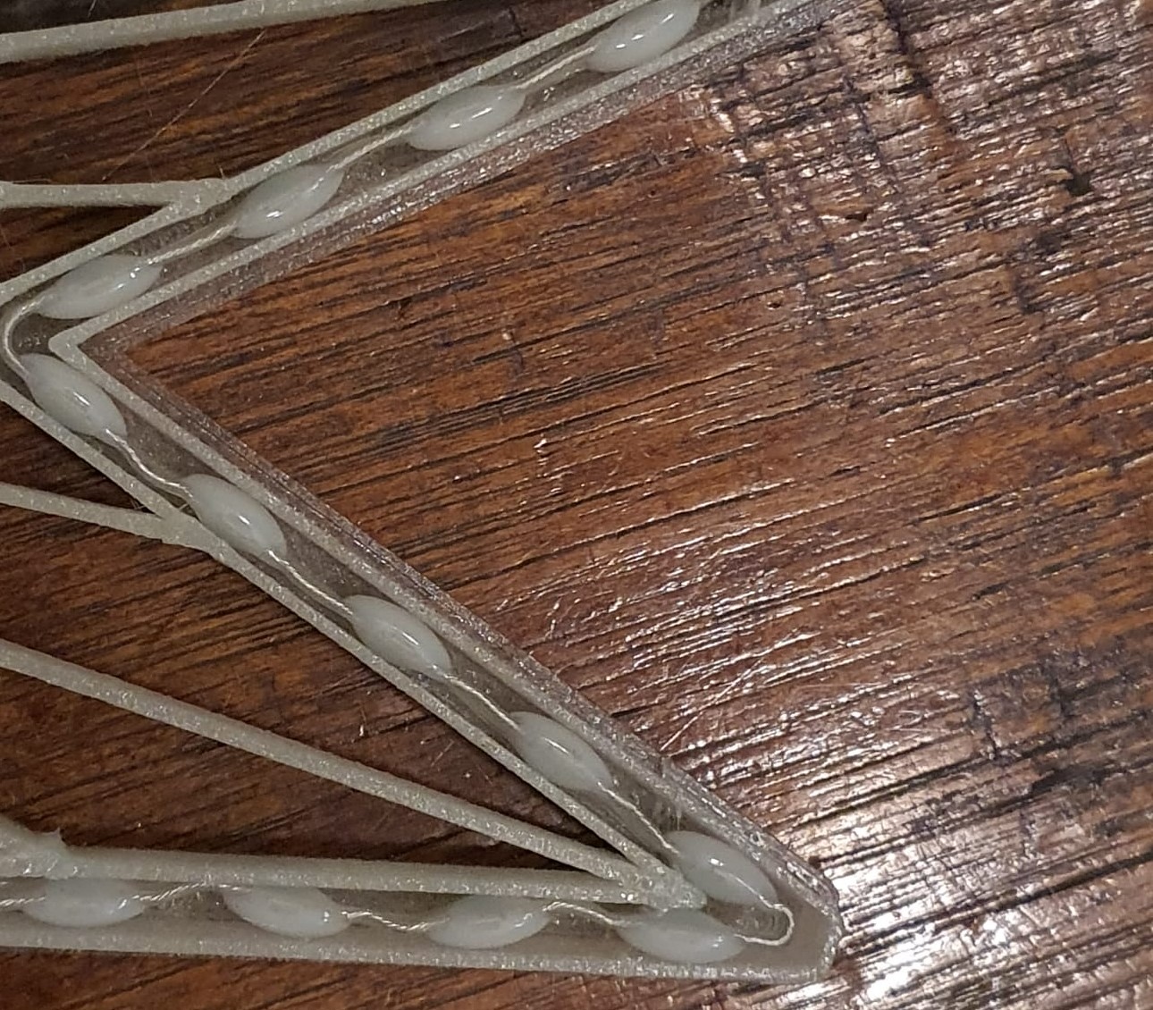
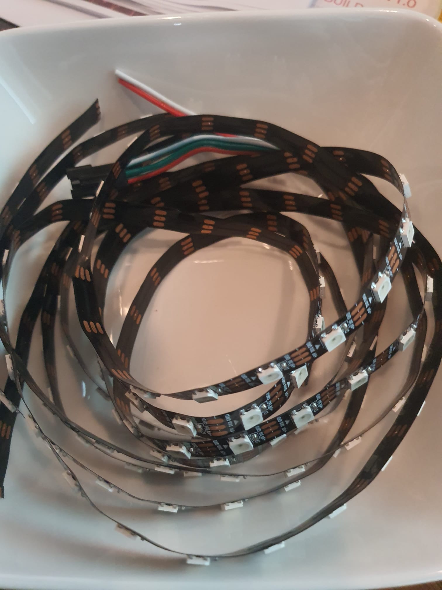
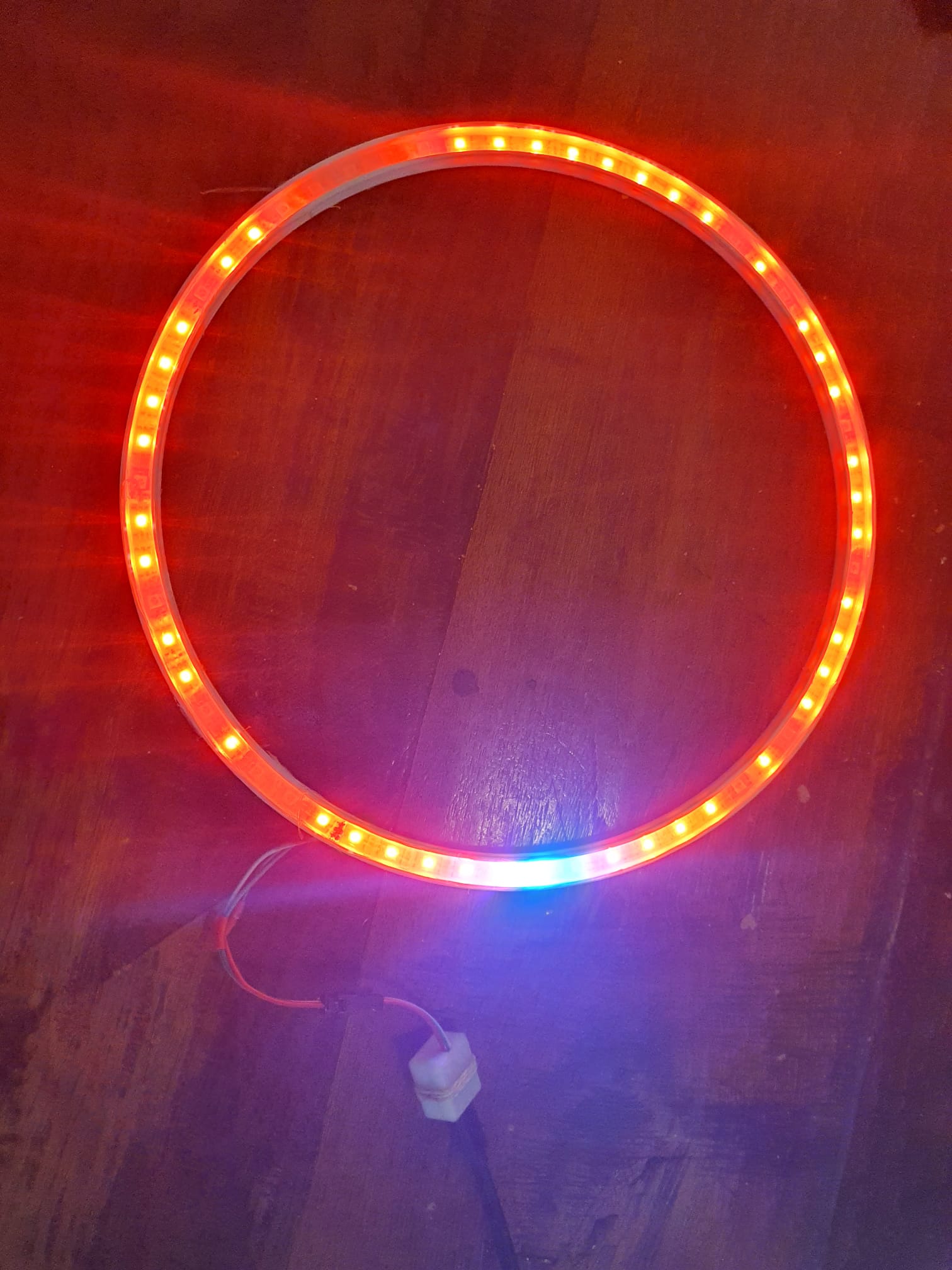
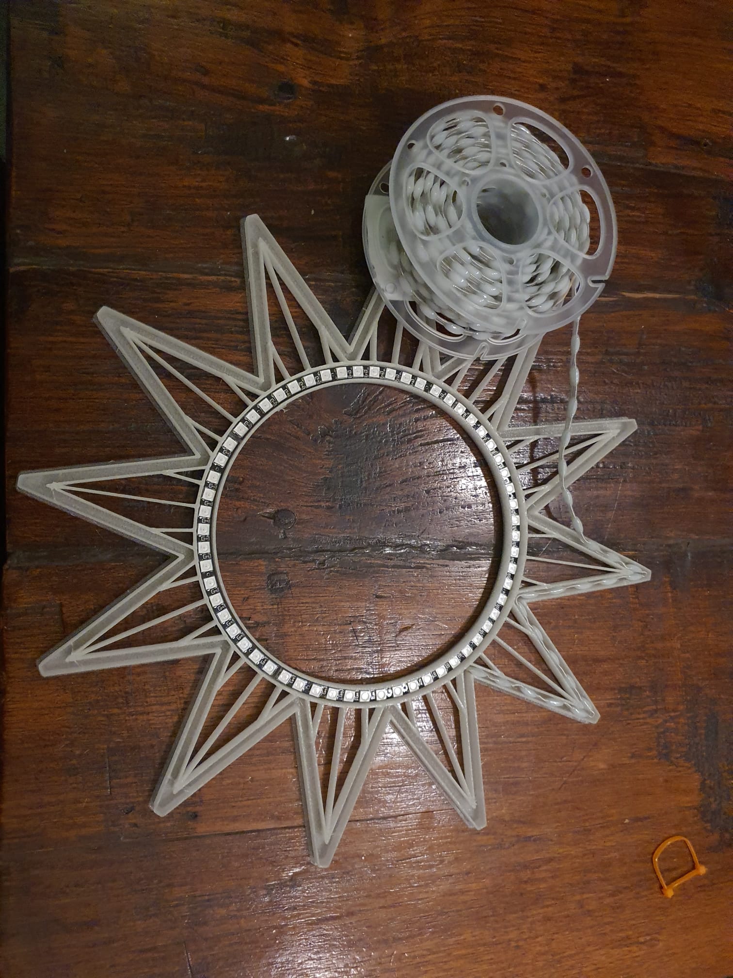
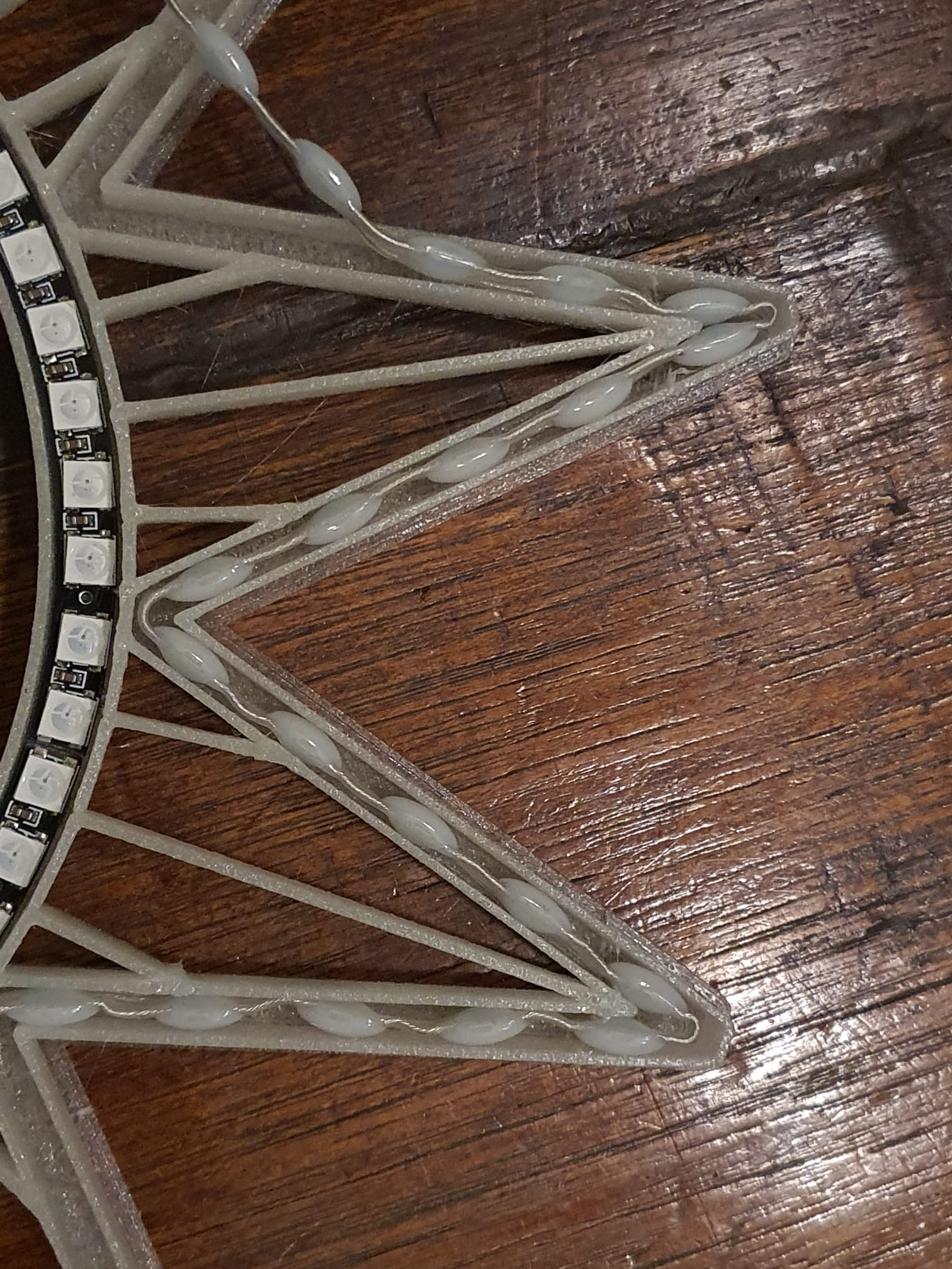
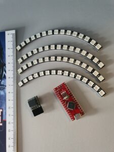
Versie 1: 60 cm kerst zonnebloem met 300 LEDS: Of deze natuurlijk, met een snoerstrip in zowel de binnenring als de bloembladen, samen met 300 stuks WS2811 ‘druppels’ elke 15 mm: (60 in de binnenring en 240 in de ster).

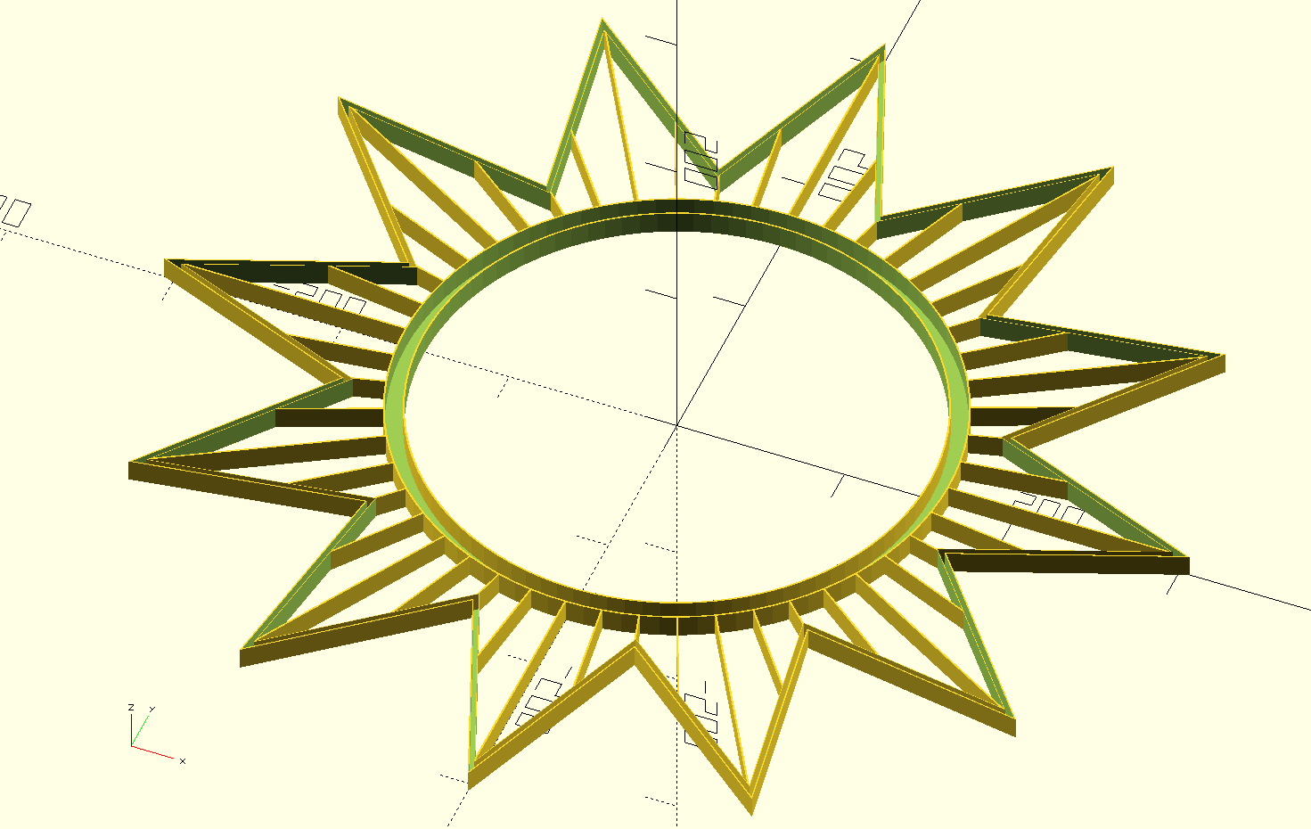
CLOCK_DOWNLOAD_600mm_12points-star_240LEDS_and_ring_60_LEDS_cable_2812_15mmLEDdistance_V12_2024_11_24

Doneer alsjeblieft $1 aan mijn paypal account als je (delen van) mijn ontwerpen gebruikt zodat ik dit kan blijven doen

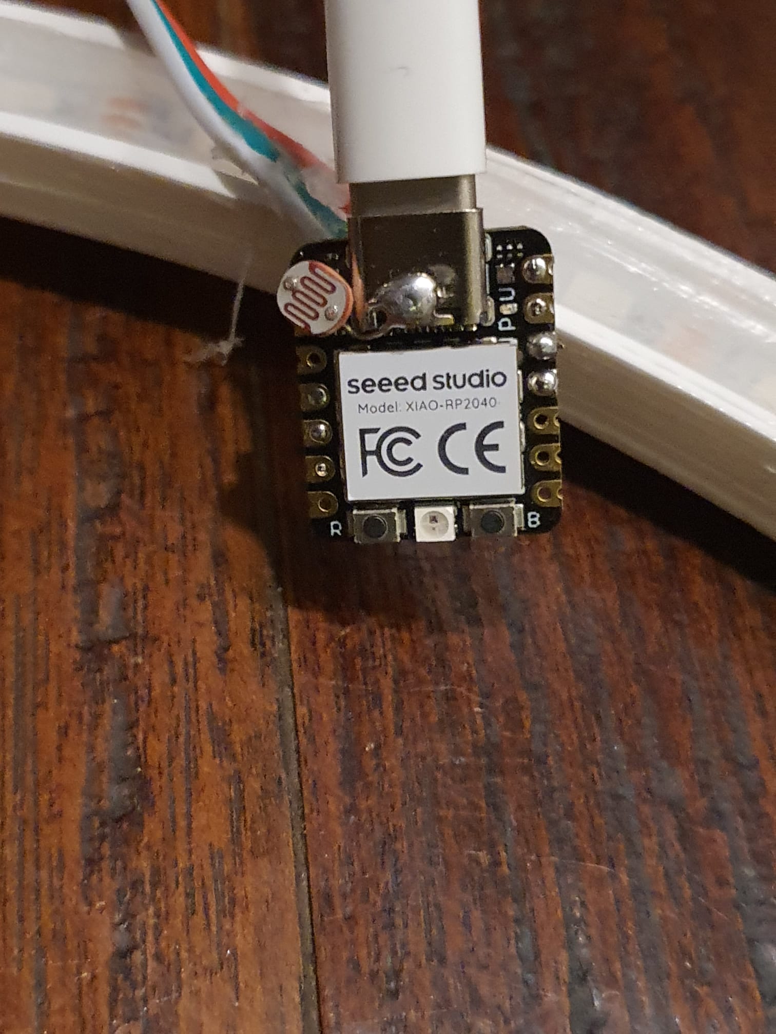
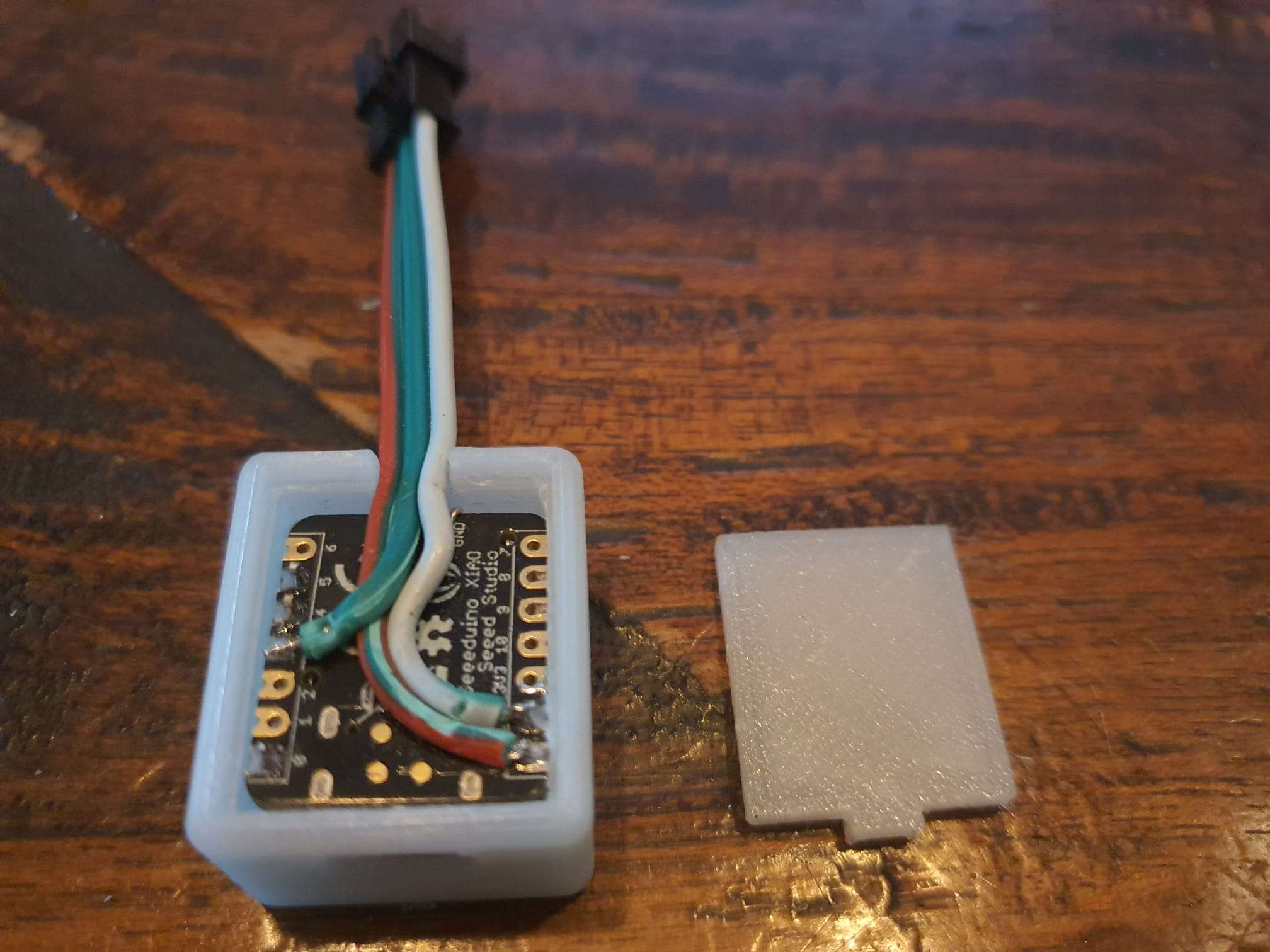
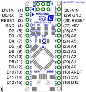
De besturing doen we voor alle versies met een Seeeduino XIAO RP2040 microcontroller en de voeding is een gewone USB-C 3 Ampère snellader. De LEDS worden geregeld op basis van het omgevingslicht zodat de LEDS overdag ook zichtbaar zijn.

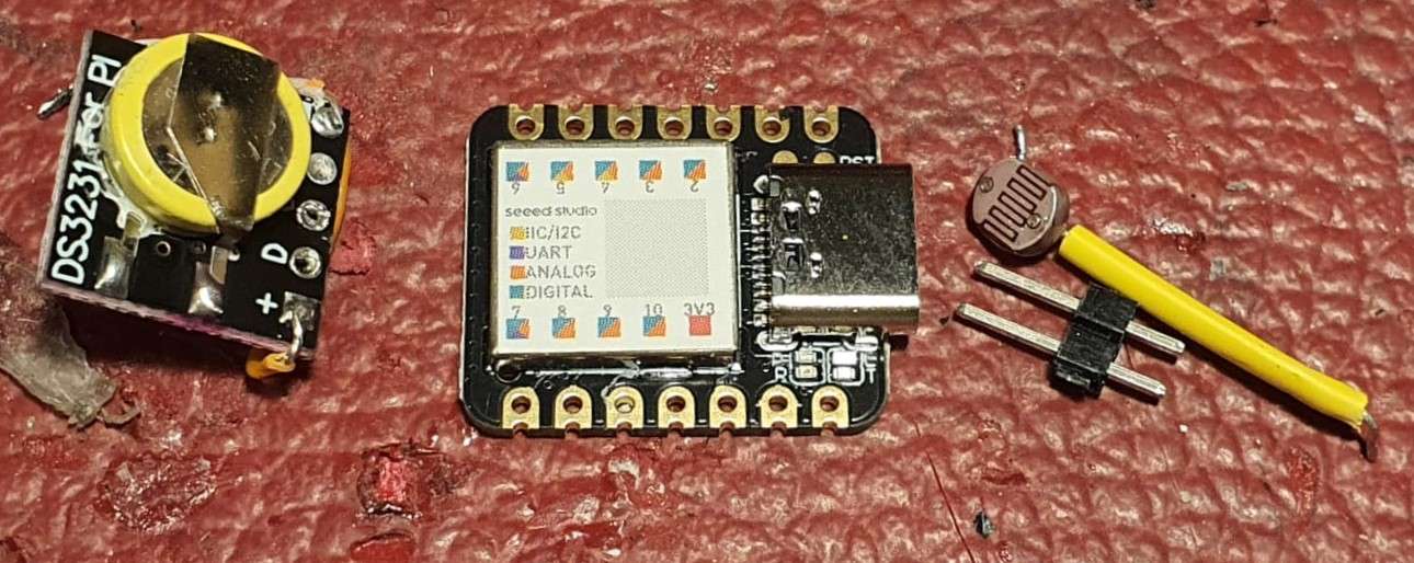
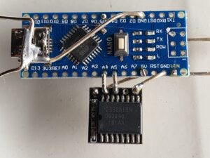
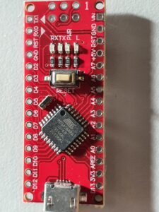
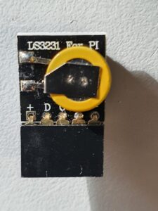
Boven zie je links de clock module, midden een XIAO-SAMD processor en rechts de LDR en de header tussen processorboard en de klokmodule’s data verbindingen
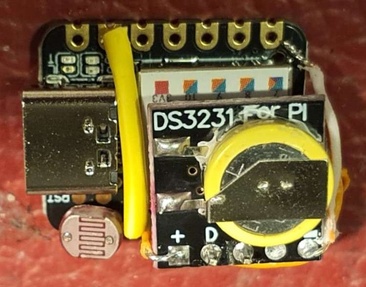
Weer een SAMD maar nu bijna alles gesoldeerd, alleen de GND aansluiting hangt hier rechtsboven nog los.

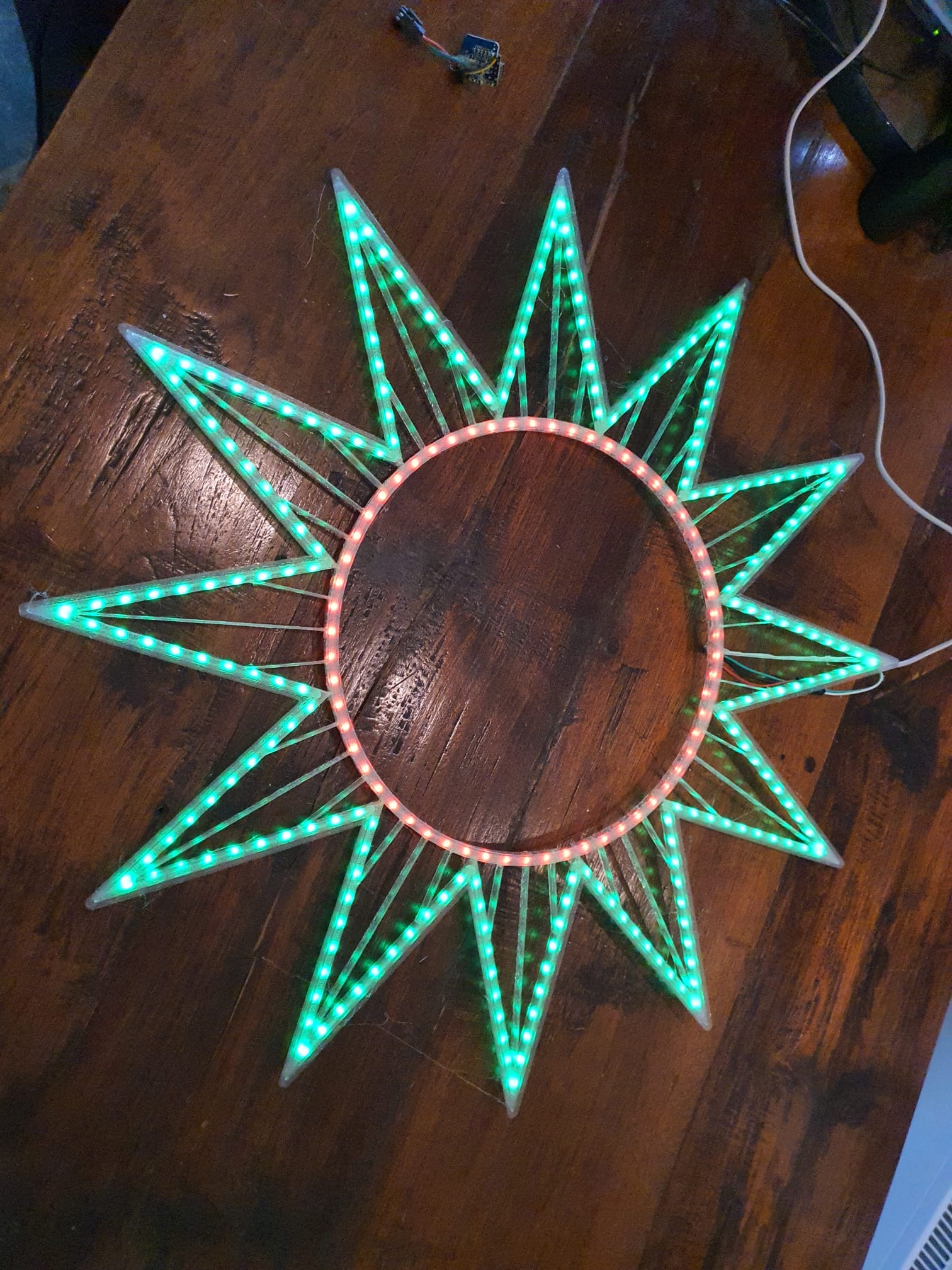
Versie 2: 60 cm kerst zonnebloem met 240 LEDS: Er gaan bij deze versie van de kerst zonnebloem ‘gewone’ LEDSTRIPS in met veel LEDs met een repeteerafstand van 1,65 cm .

In deze tweede versie gaat er in de binnenring een strip plat met 60 RGB LEDs: (KLIK voor de downloads van ‘how to make’ en de programmatuur) . Het vergt wel wat uitzoeken om de klok en alle LED’s een beetje leuk aan te sturen. Succes!

In de bloembladen ven de tweede versie gaat een strip erin op z’n zijkant met 180 LED’s.  Per bloemblad zitten er dan 15 LEDs (180/12) in.

Om dit ontwerp te printen heb je een printbed nodig van minimaal 60×60 cm bruikbaar oppervlak.  Ik print dit op mijn Voron600.

Dit is het STL-ontwerp: (click to download STL file)

Doneer alsjeblieft $1 aan mijn paypal account als je (delen van) mijn ontwerpen gebruikt zodat ik dit kan blijven doen

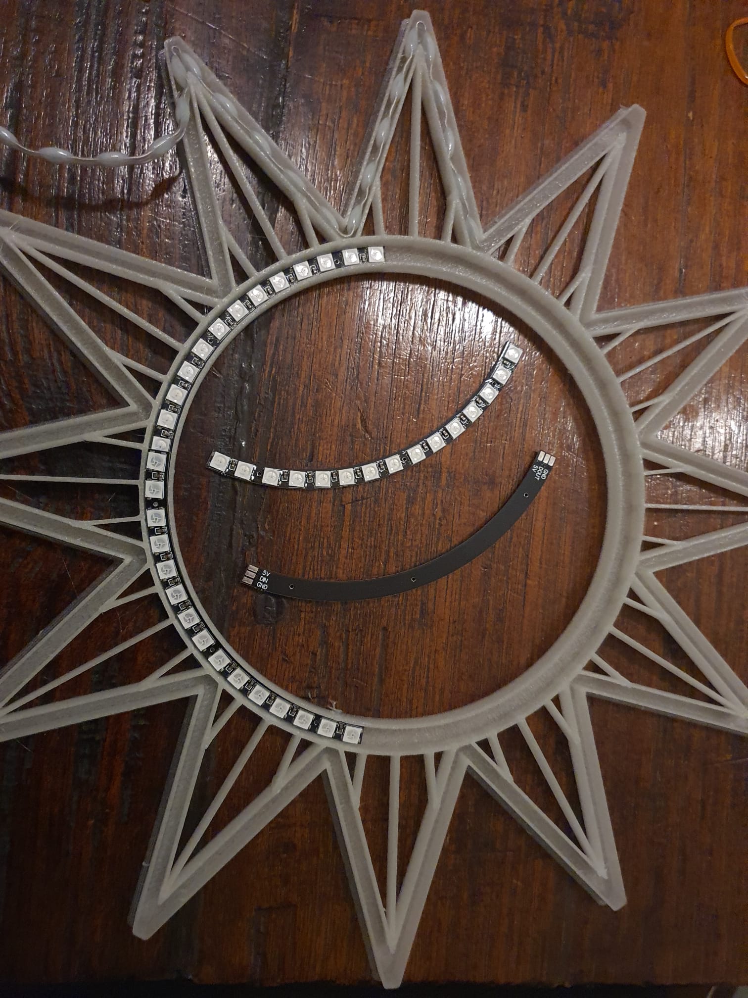
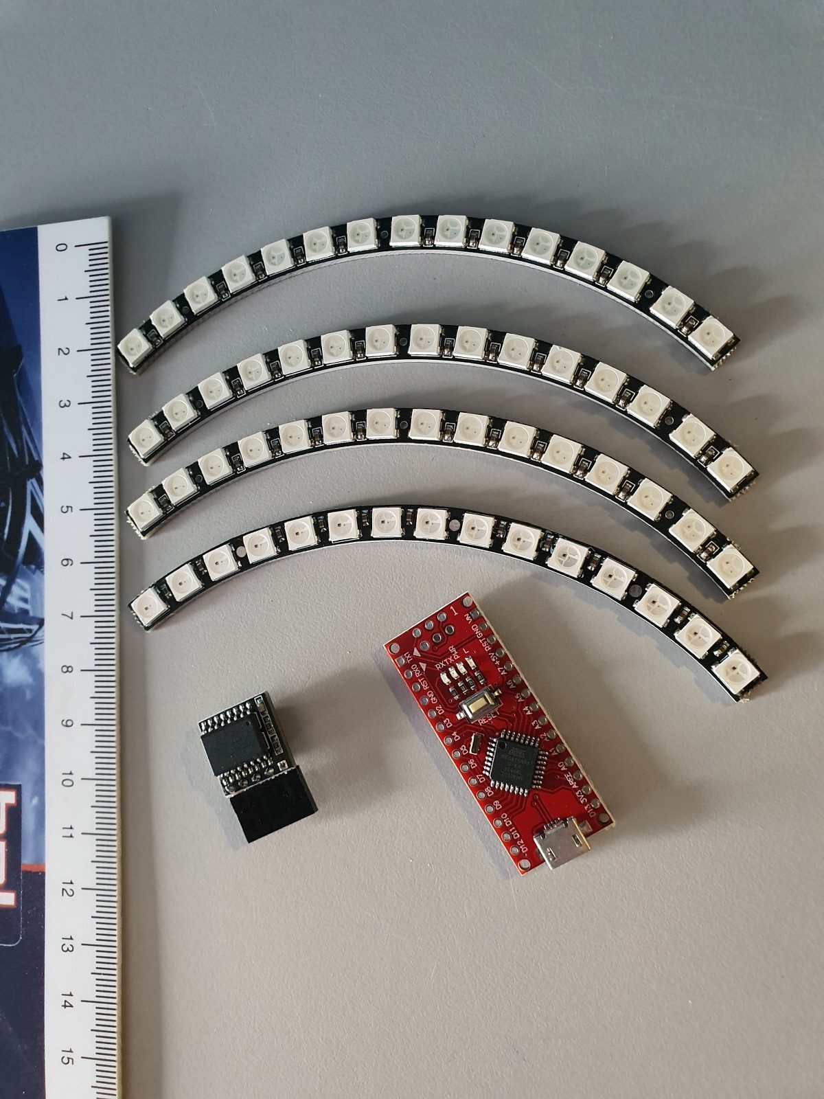
Versie 3: 30 cm kerst zonnebloem met 180 LEDS: En er is ook een versie voor een printer met een 300x300mm printbed gemaakt, de binnenring is hier gemaakt met een setje van 4 kwart ronde delen van elk 15 leds die met z’n vieren een 60 LEDs ring met een diameter van ca 160mm maken.  De bladen zijn hier weer gemaakt met een snoerlint van WS2812 LEDs om de 15mm, samen zijn dat er 120 in 12 bladen, dus 10 WS2812 LEDS per blad:

SMALL_CLOCK_12_points-star_and_mini_ring_60_LEDS_V15_FINALVERSION_20241127

 Doneer alsjeblieft $1 aan mijn paypal account als je (delen van) mijn ontwerpen gebruikt zodat ik dit kan blijven doen


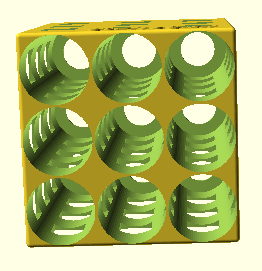
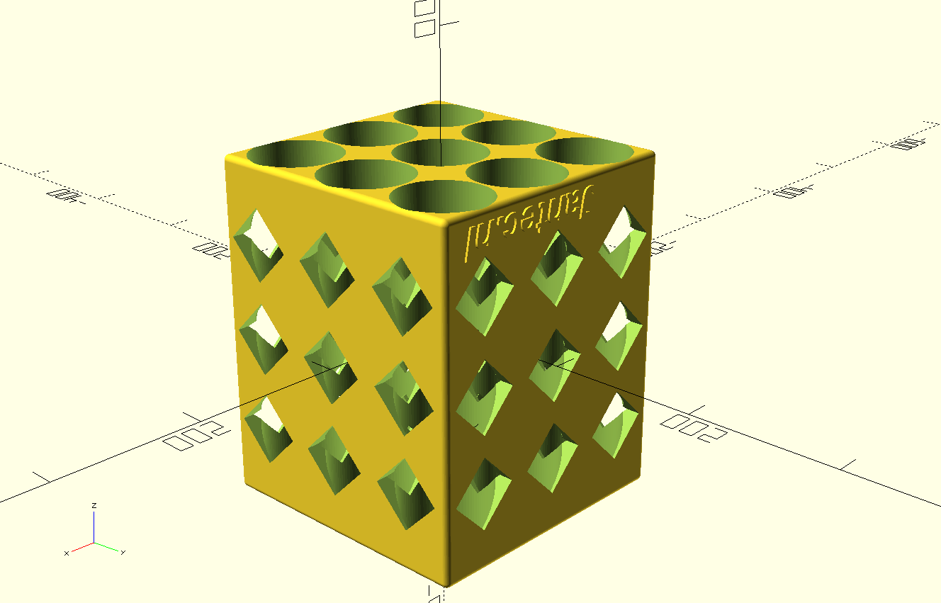
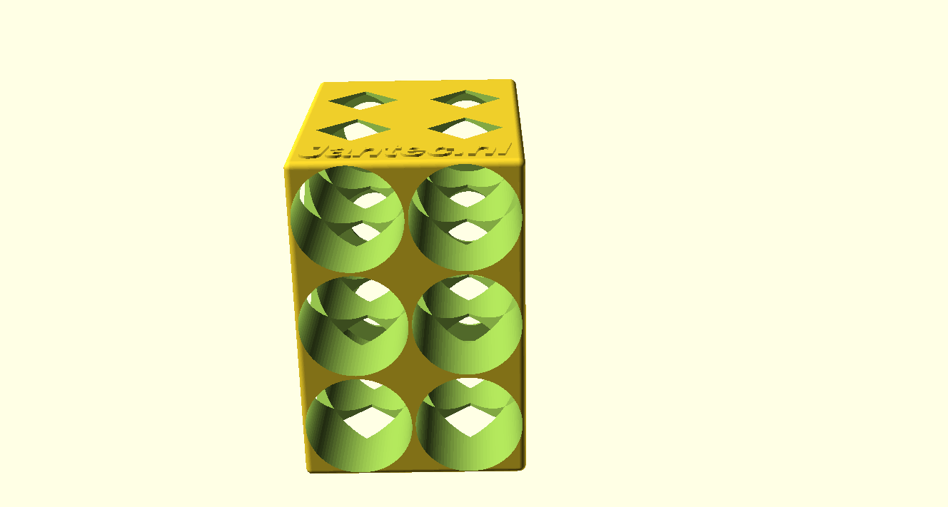
STL download bierflesjes organizer voor in de koelkast C) Jantec.nl


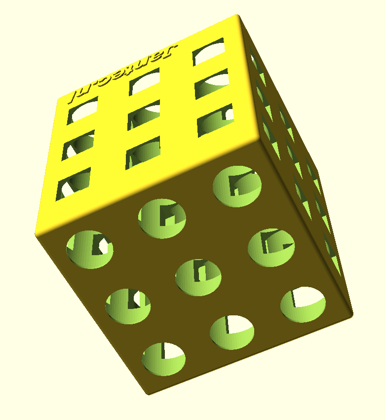
Achterkant

En zo staat ie in de koelkast!

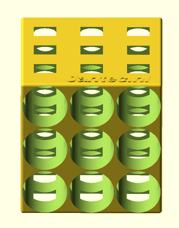
Voorkant en doorkijkje naar achter

Voor gewone 330cl bierflesjes

De box in 3×3 flesjes uitvoering is 238 mm diep en 197mm hoog & breed.

Printen gaat het best met de achterkant van de flessenbox op het bed, dat is het deel waar de ronde gaten aan de achterkant van de flessen het kleinst zijn.

Als je printer max 200x200x200 mm aan kan, print dan de Z op 80%.

De flesjes steken er dan aan de voorkant  4 cm uit, dat kan ook prima!

Print meer boxen en zet ze naast elkaar, op elkaar etc.

beer bottles 3×3 fridge rack 2023 04 20


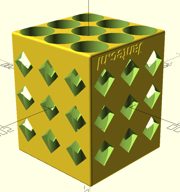
En een aangepaste versie om te printen zonder support:

beer bottles fridge rack with 45deg squared side holes 2023 04 20


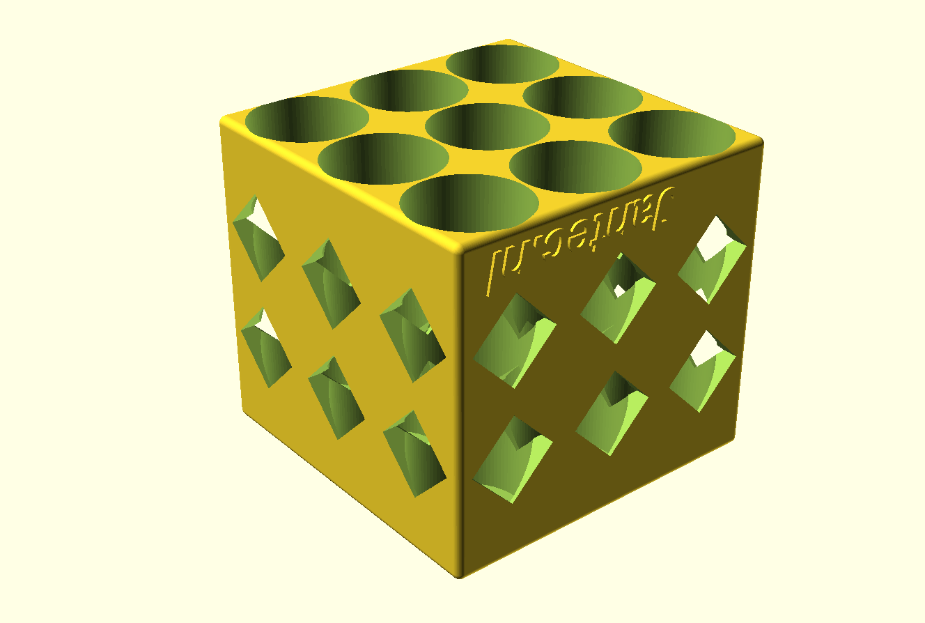
En een korte versie::

beer bottles SHORT fridge rack with 45deg squared side holes 2023 04 20


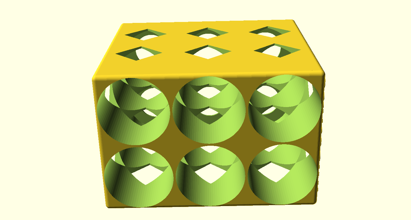
Kort en kleiner in 2×3 uitvoering:

beer bottles 2×3 SHORT fridge rack 2023 04 21


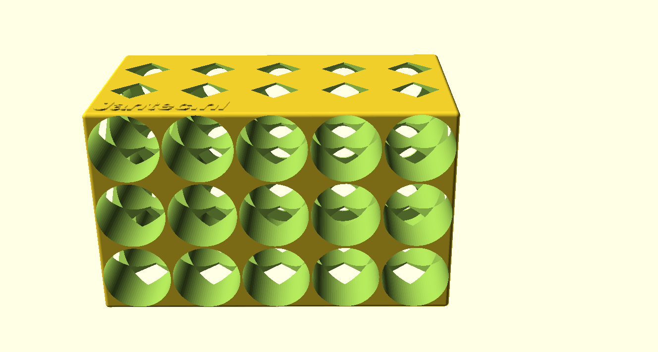
En nog een hele grote wanneer je een 350mm brede 3d printer hebt:

beer bottles 5×3 fridge rack V2d 2023 04 21

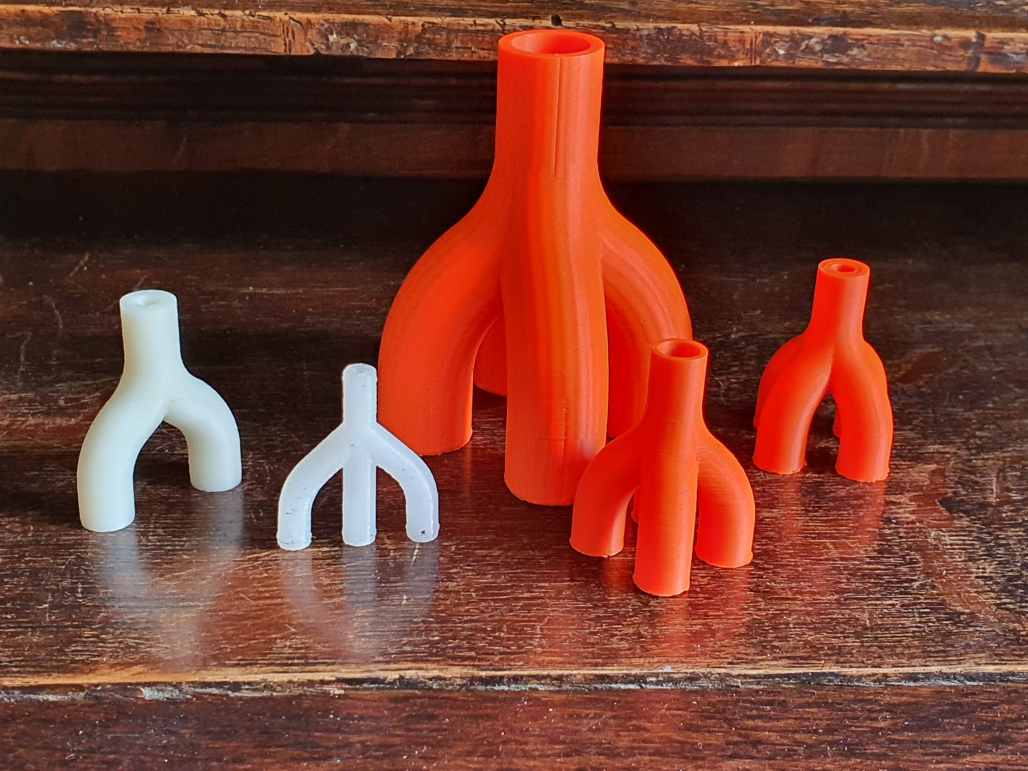
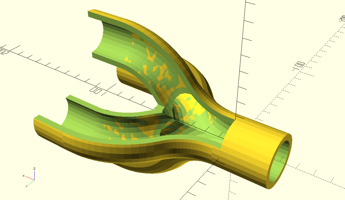
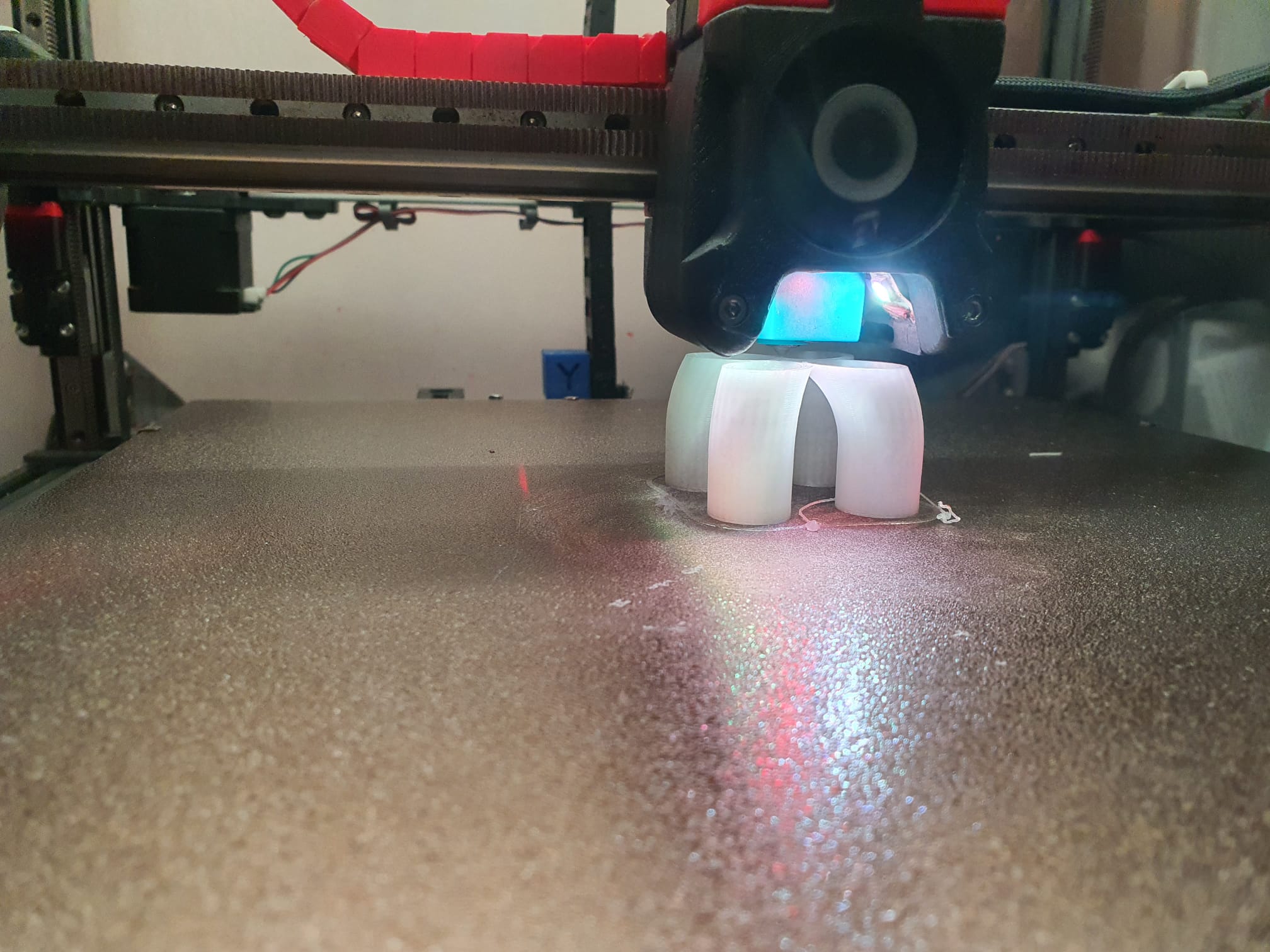
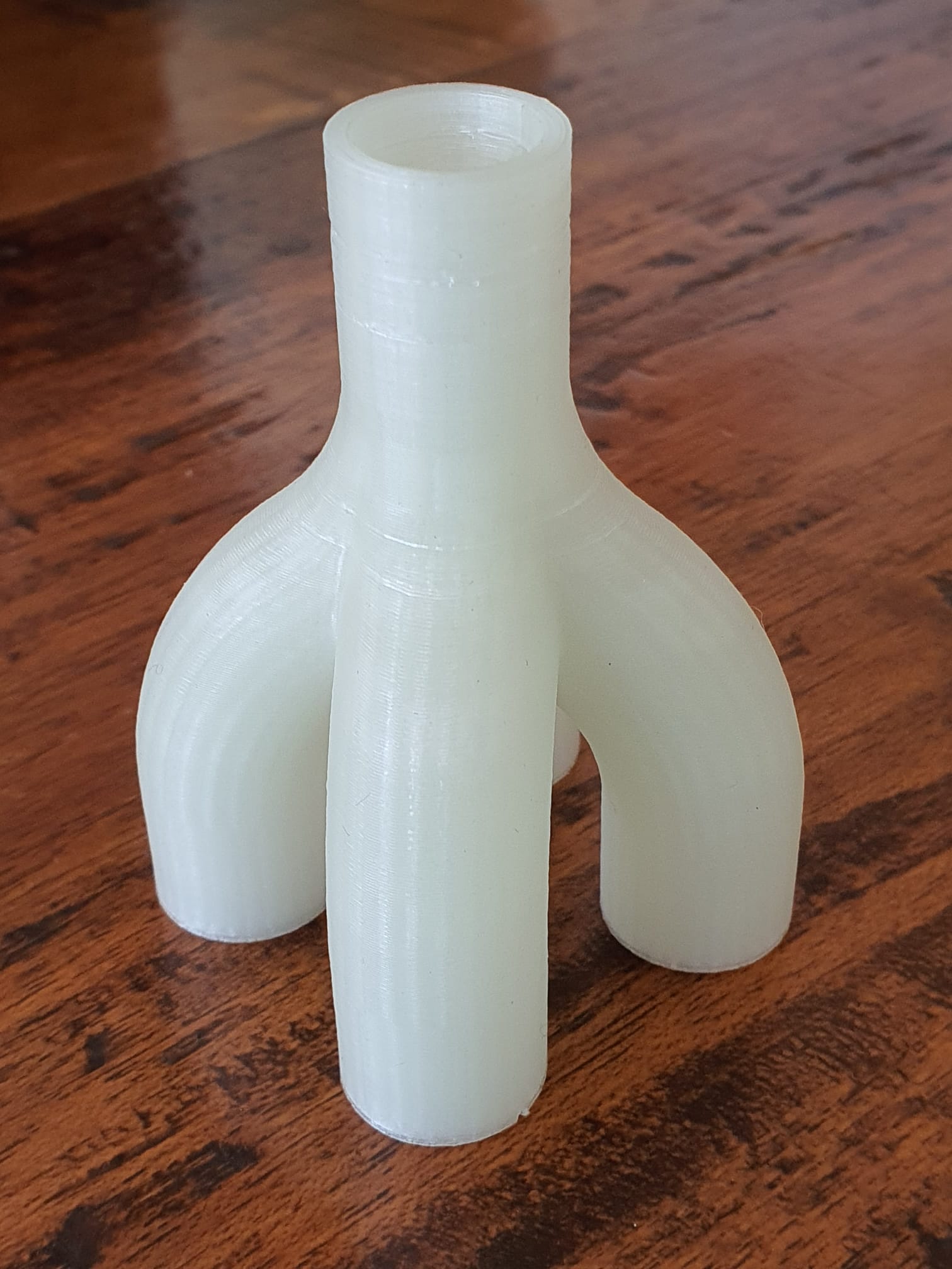
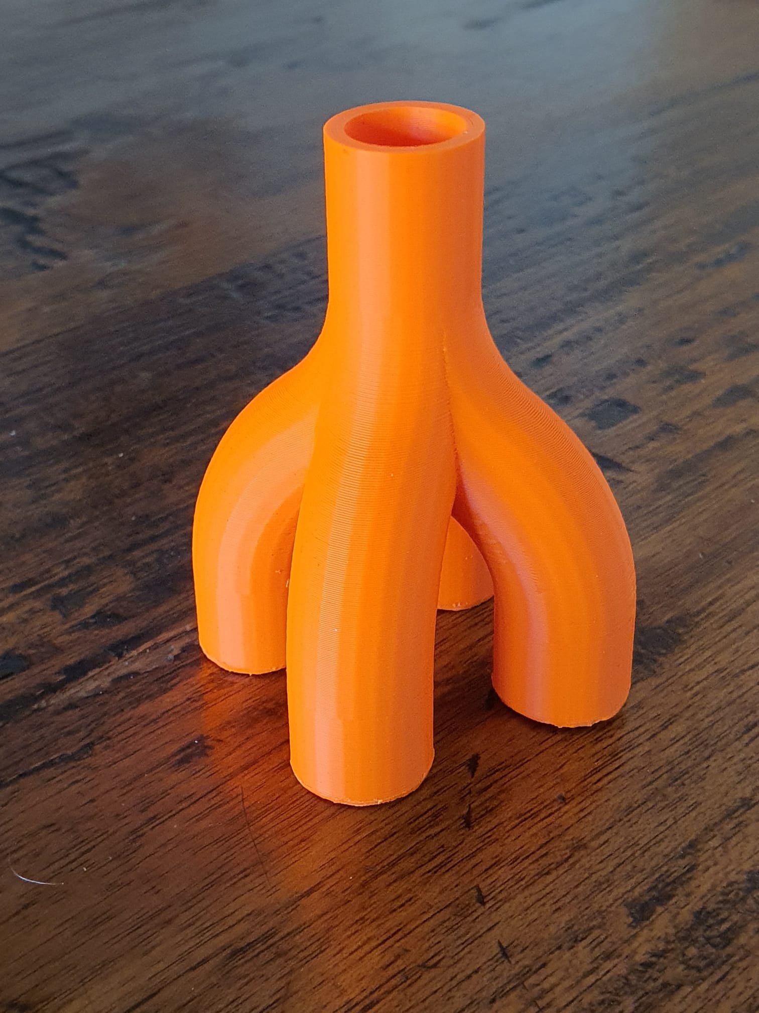
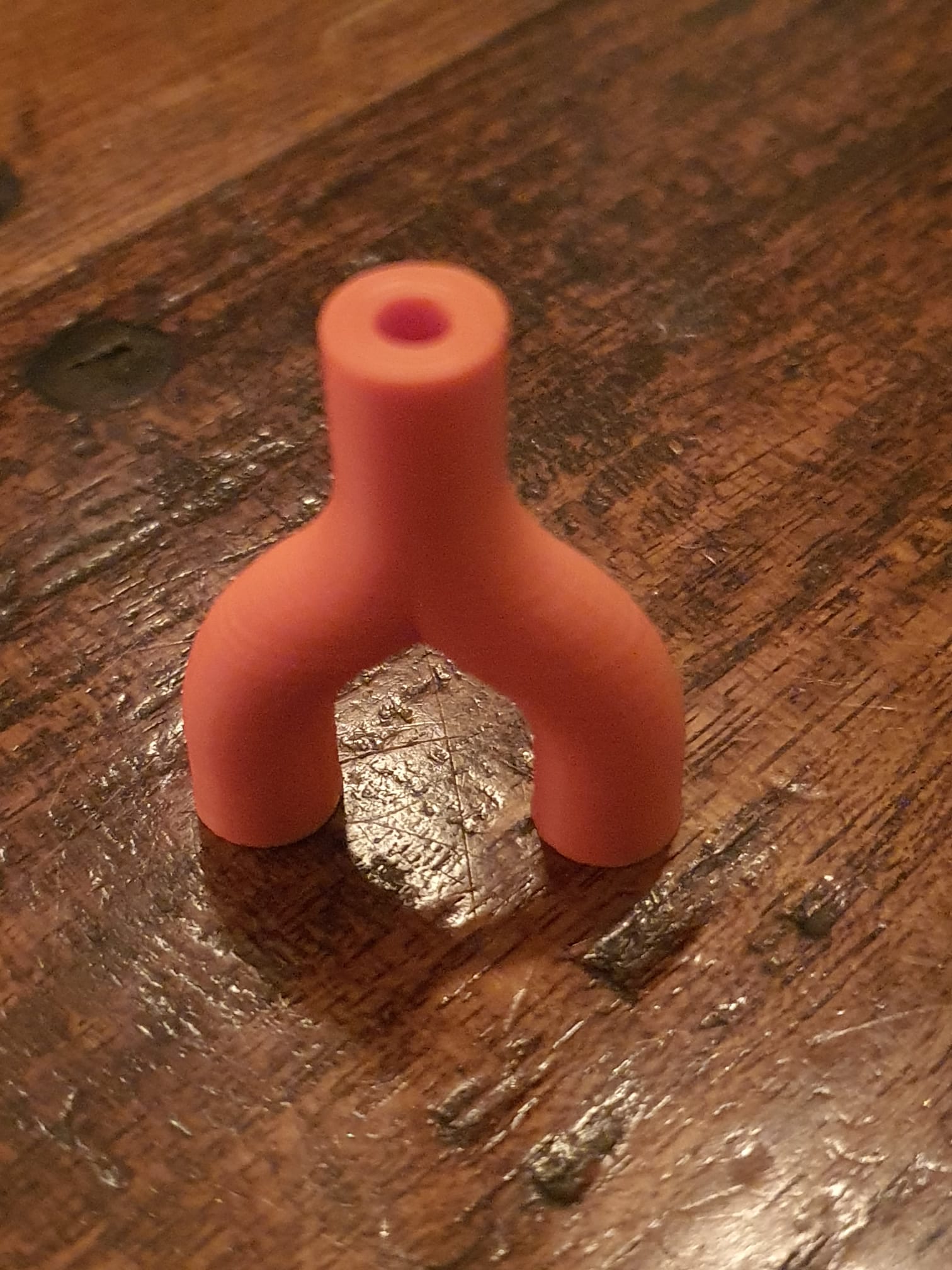
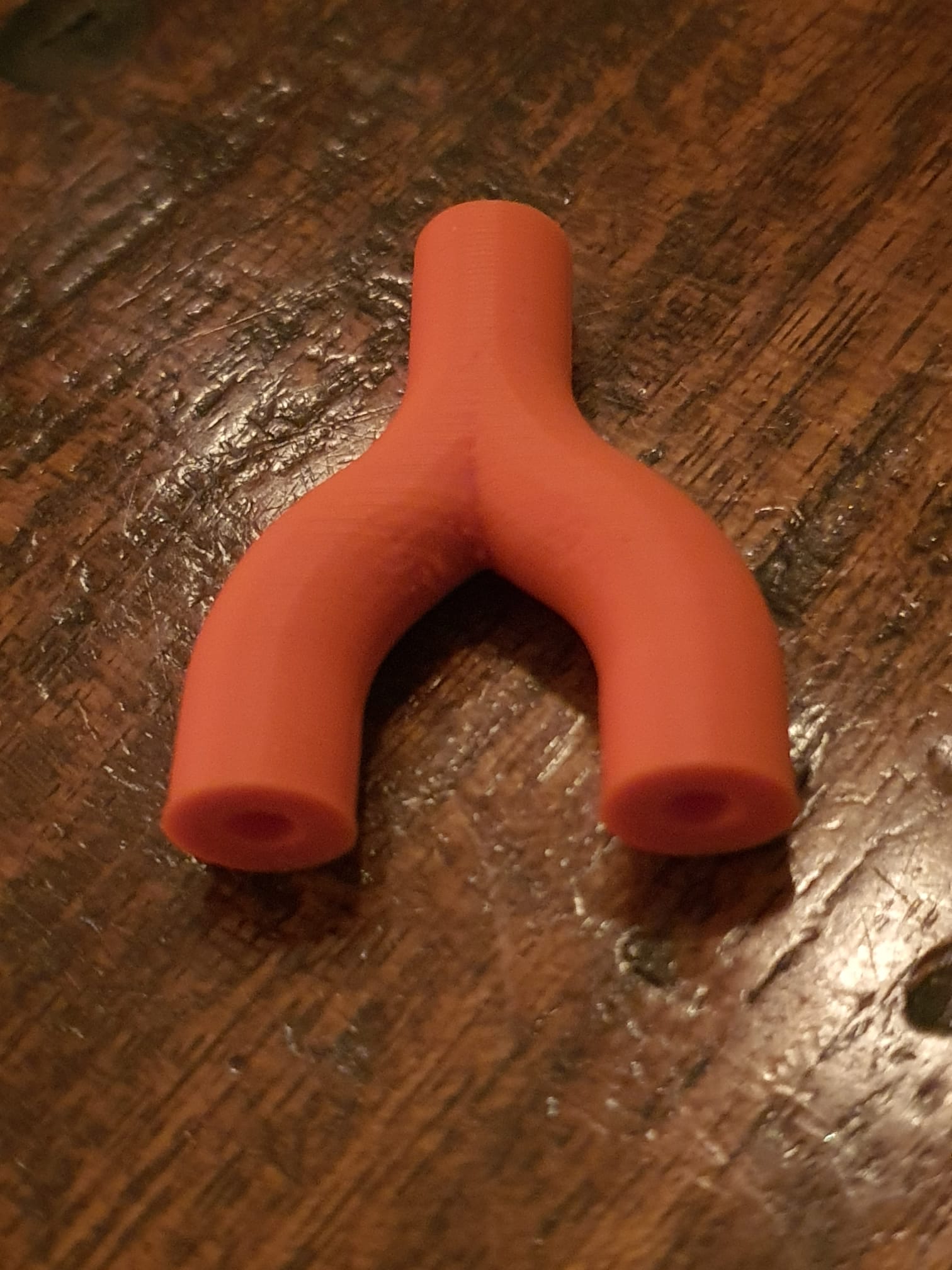
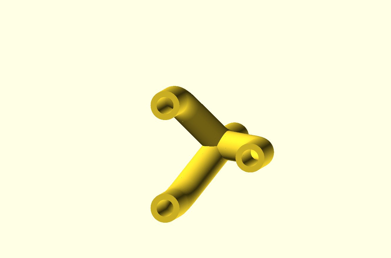
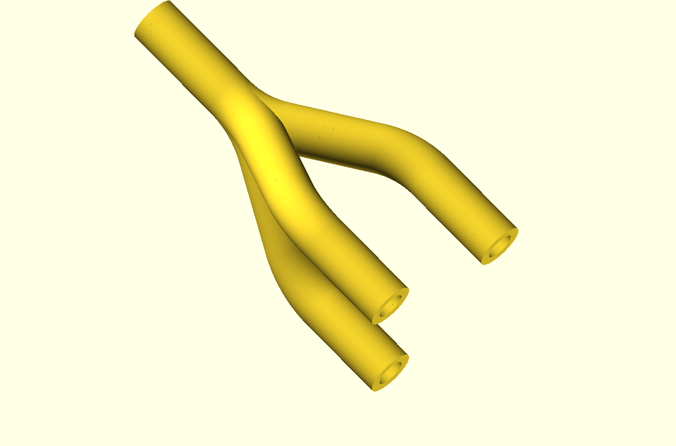
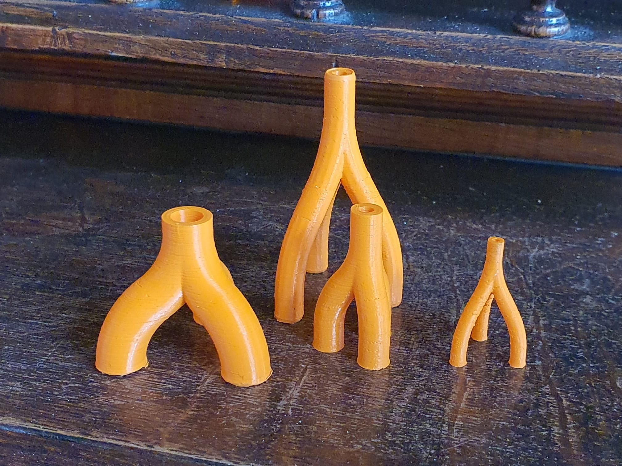
Meerdere holle samengestelde buizen samenvoegen met Openscad curvedPipe libs

OPEN curvedPipe for pipeconnector 4 into 1 FLAT 2023 05 01 V4 dev a.SCAD

OPEN curvedPipe for pipeconnector 4 into 1 FLAT 2023 05 01 V4 dev a.STL


Kijkje in de binnenkant.  De instellingen van Openscad moeten behoorlijk omhoog v.w.b. de CSG limiet om de cutouts aan te kunnen qua renderen.

Video van WhatsApp op 2023-05-02 om 23.08.14

snelle draft met 0.3mm LH en 220mms/ geprint op de Voron 2.4 50% scaled

in oranje ASA op de Voron 2.4 op 50% scaling

2 in 1 met dikke wanden 25% scaled, ASA op Voron 2.4. en 8.5 mm buiten diameter

Pipeconnector 2 into 1 all tight_hollow 2023 05 03 V4 dev b STL download

NB: Ik heb er voor gekozen om de 3 libs in de main code op te nemen zodat ik waar nodig nog makkelijk kan wijzigen zoals alles omzetten van child naar children.


Pipeconnector 3 into 1 all hollow 2023 05 26 V5 dev d 


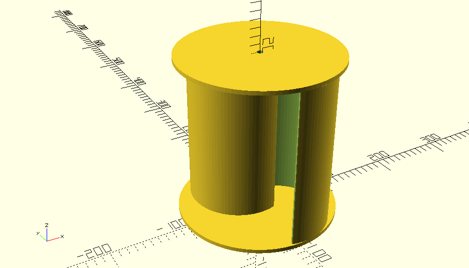
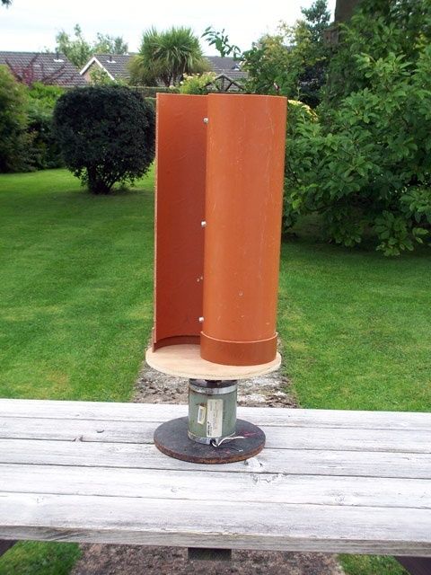
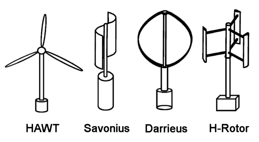
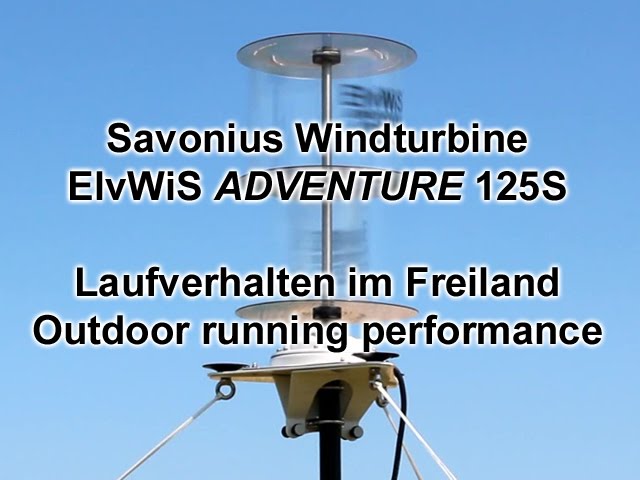
STL file download voor windturbine, genereer zelf stroom op je dak

Vertical wind turbine Jantec.nl 2023 04 22 V2 DEVb

STL file om met je 3d printer uit te printen, ca 20 cm breed en ca 20cm hoog!

Er kan een 8mm bout of draadeind van boven naar onder door om vast te maken op bijvoorbeeld een oude dynamo uit een auto, of op een DC generator., of op een stappenmotor.

Plaats het op je dak en je kan (wanneer het waait) een accu opladen of binnen je licht gebruiken!

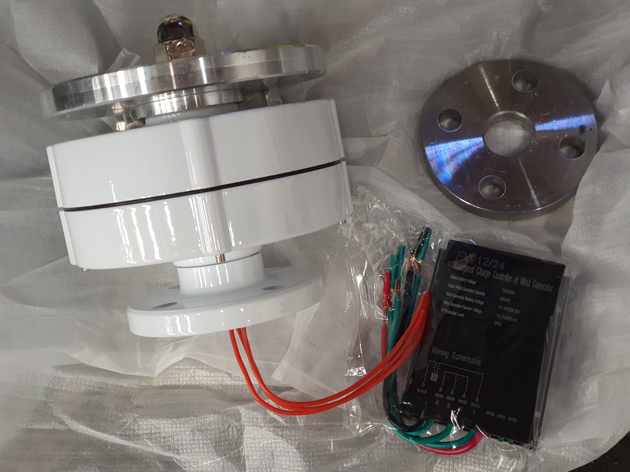
De 24V DC- & 230 Volt AC mini-windgenerator installatie:

En dit is waar de turbine op komt met 2x12V = 24V accu’s en een 24V naar 230 V inverter.

De 3-fase generator wordt met de regelaar (rechtsonder) geremd wanneer er te veel stroom wordt opgewekt…. . De montageplaat (rechtsboven) past op een 28mm buis en wordt aan de buis gelast.

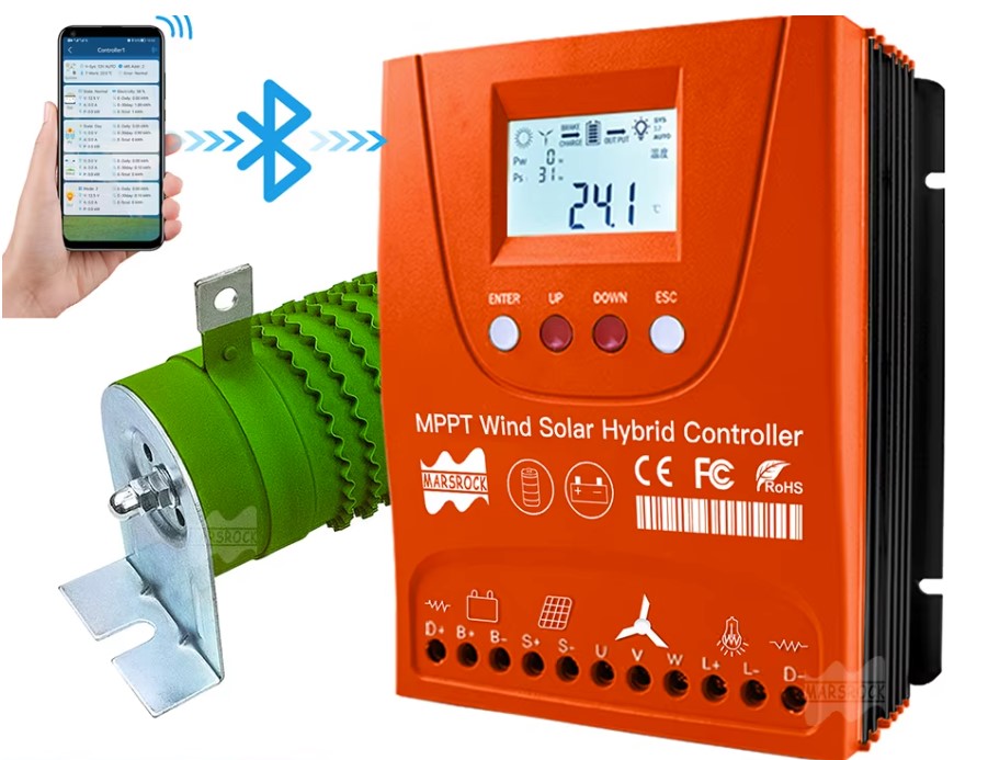
En deze “Wind1500W Solar1500W, Auto 12V 24V, External Wind-Solar Hybrid” controller heb ik ervoor aangeschaft, omdat deze zowel de zonnepanelen als de windmolen bedient (als er voldoende wind is schakelt de controller over op wind, anders gebruikt hij de zonnepanelen):

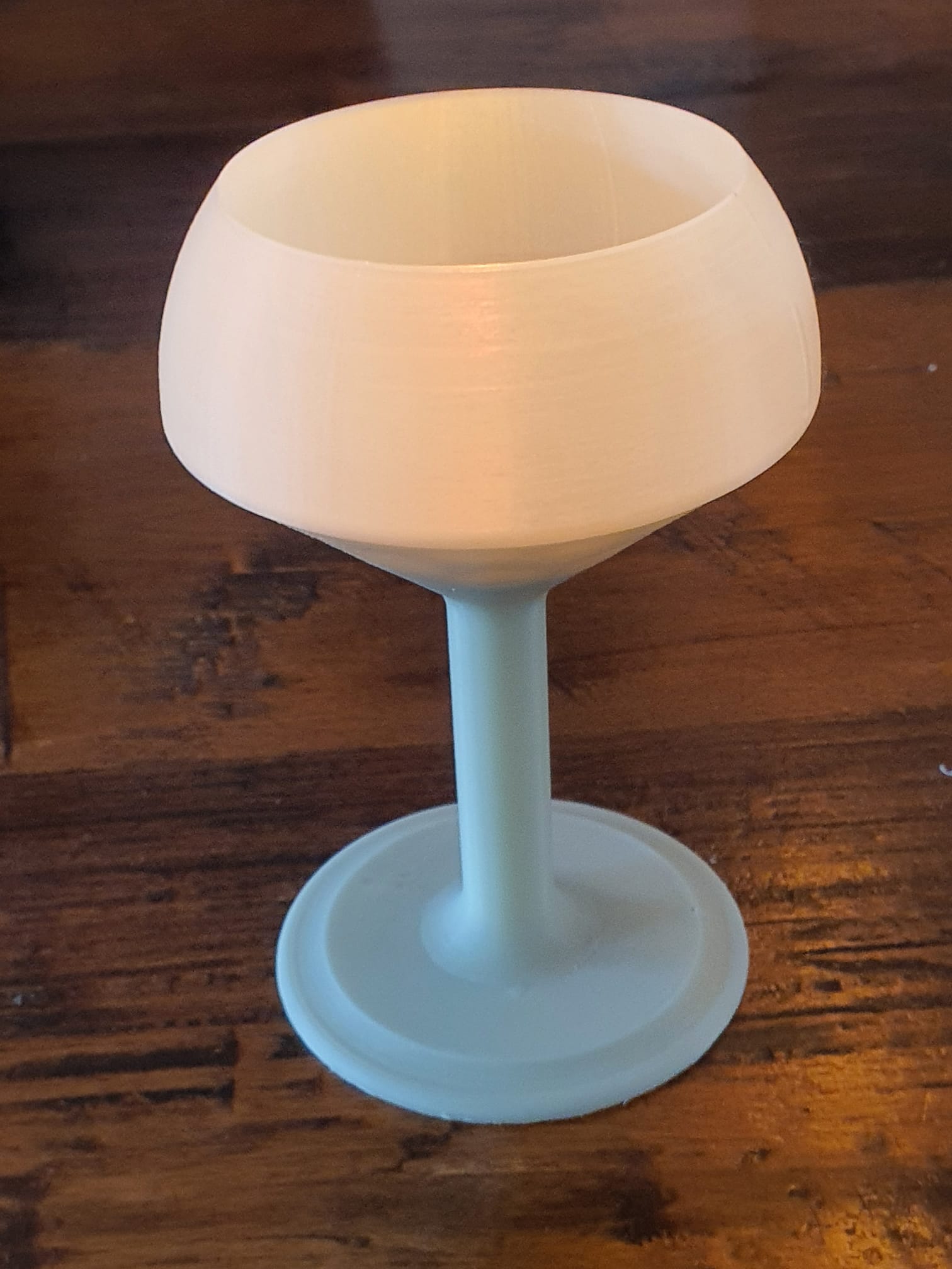
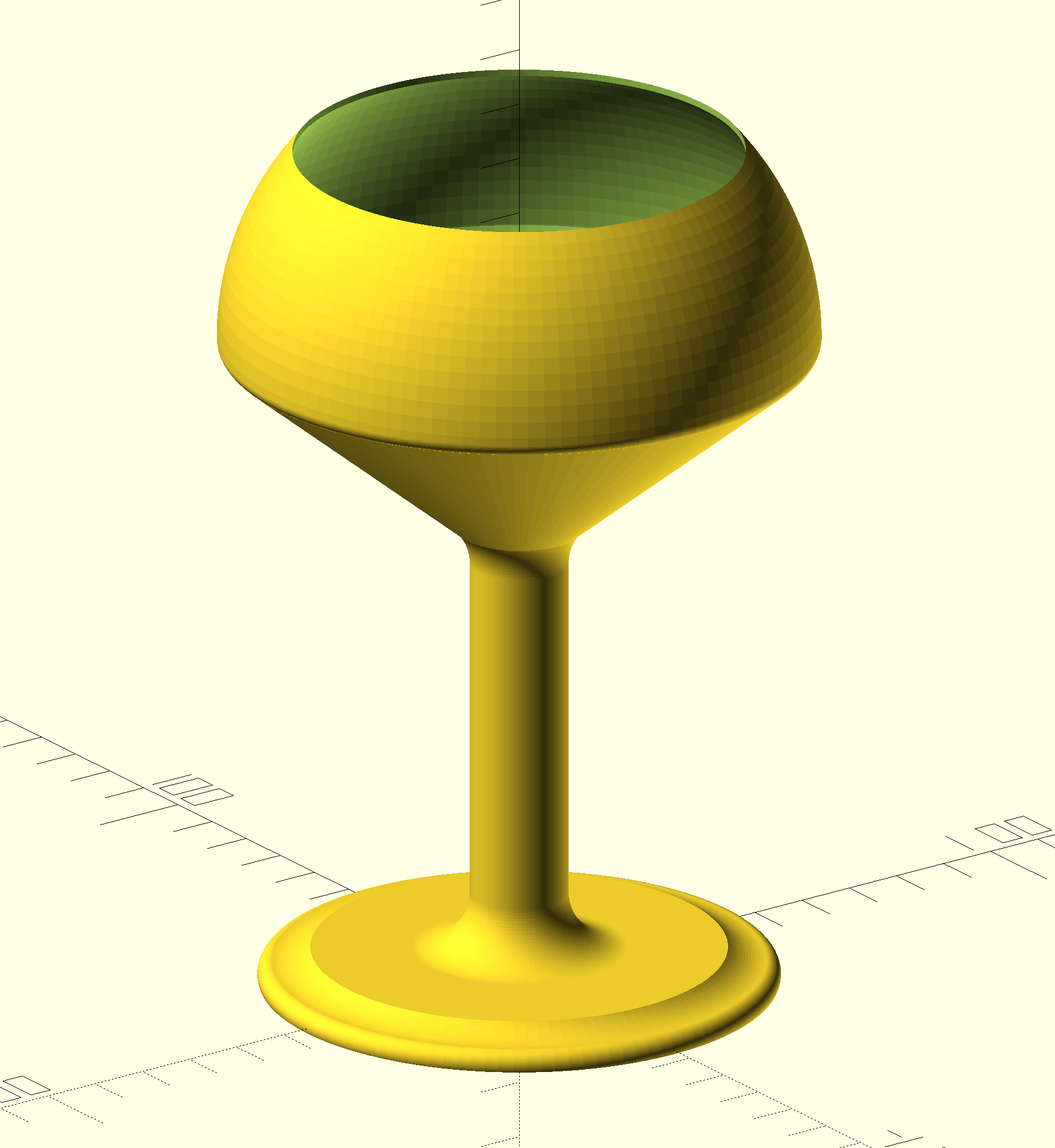
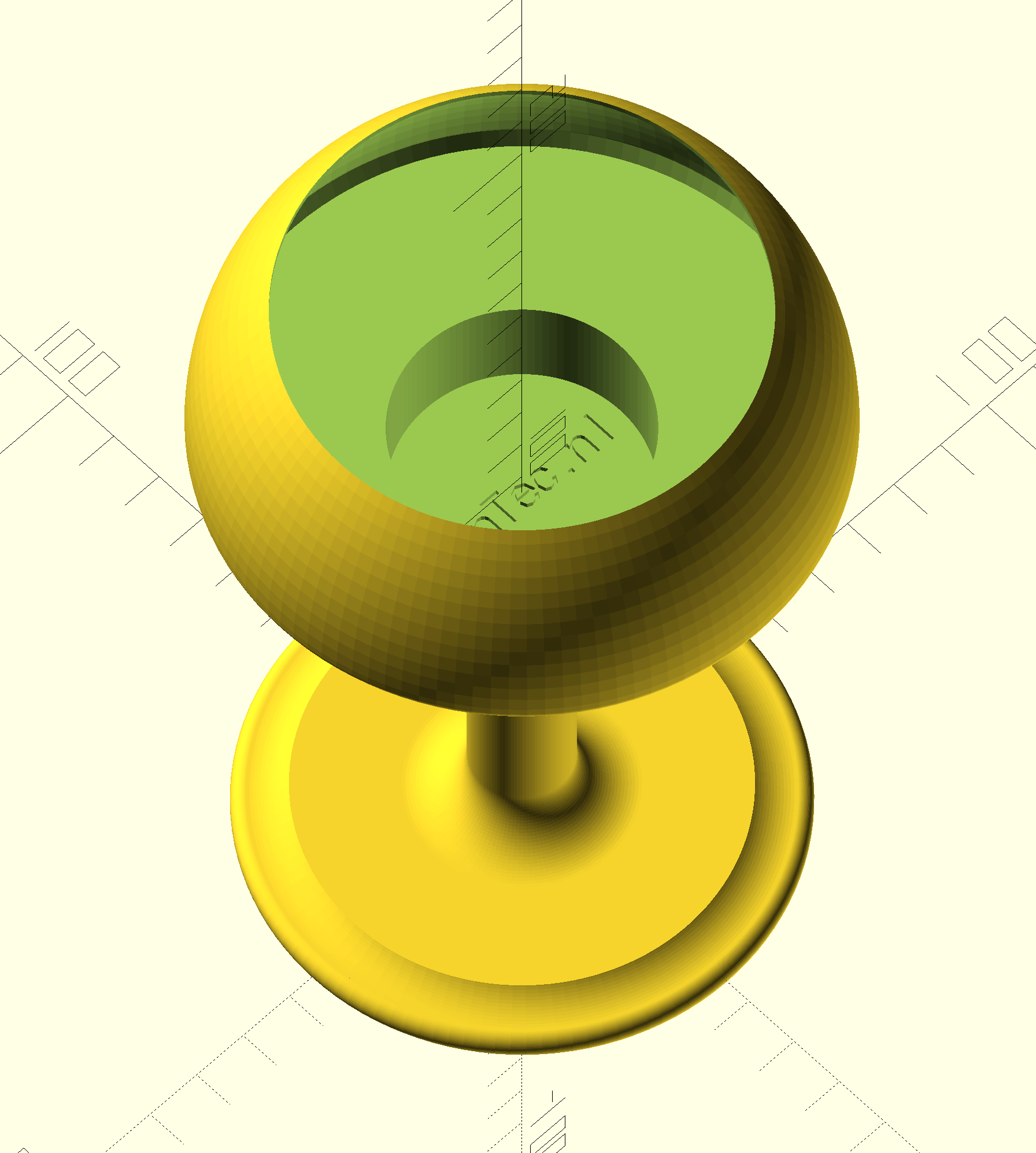
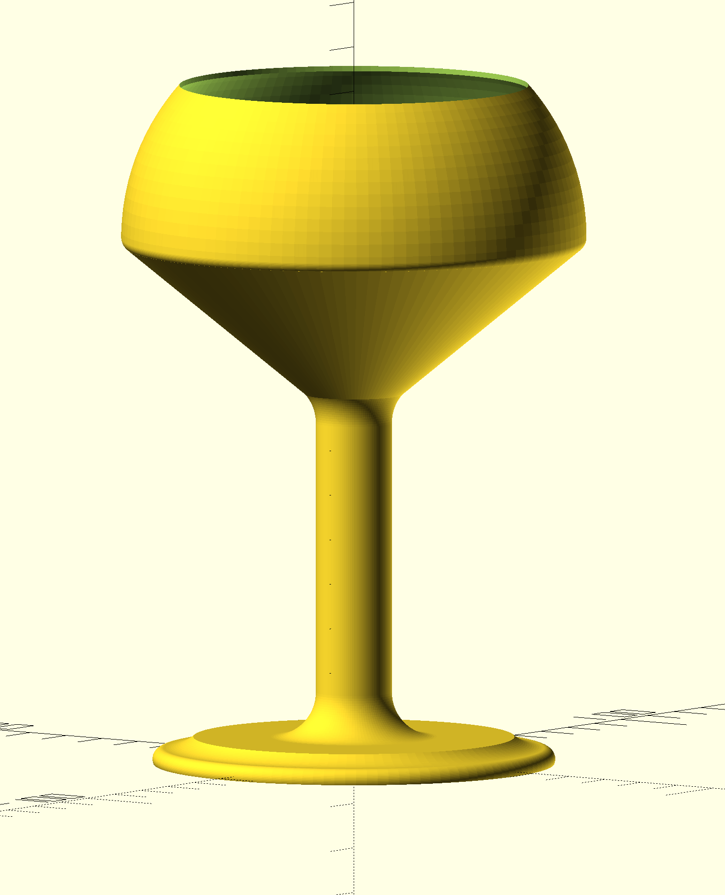
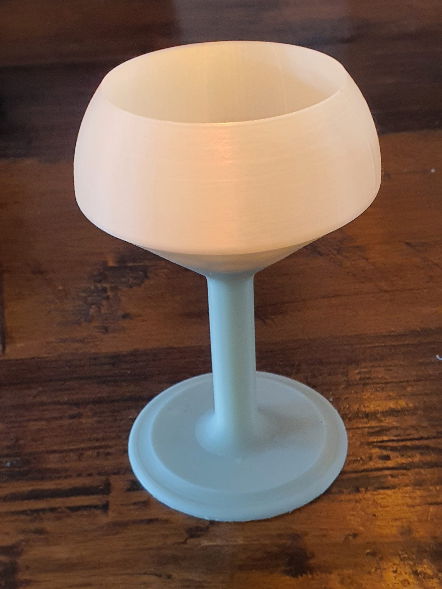
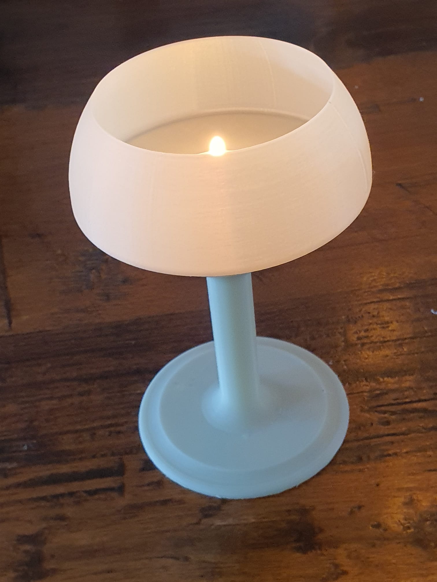
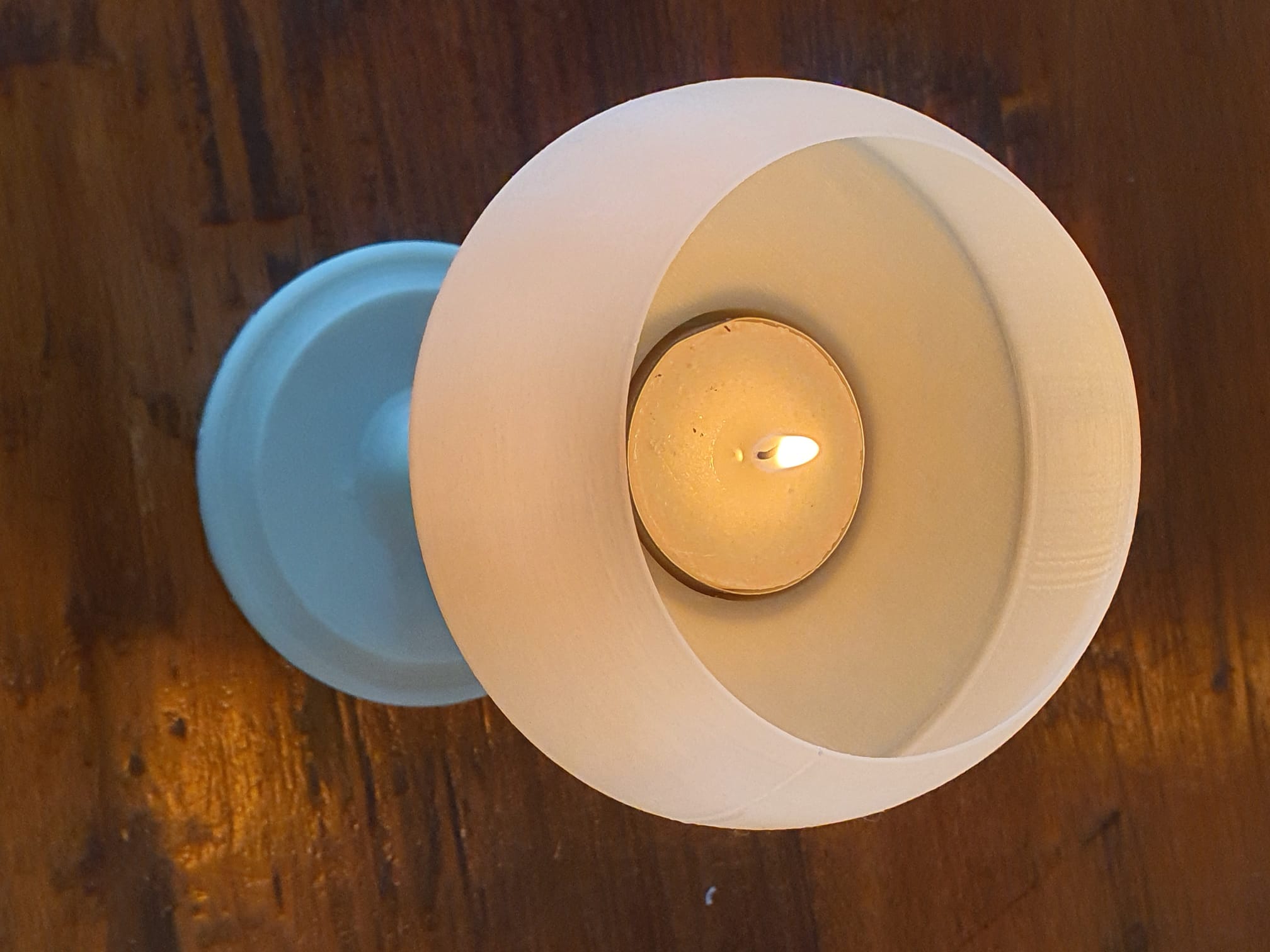
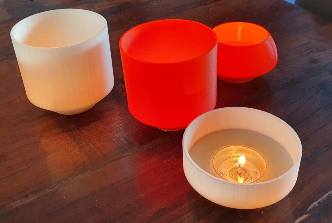
5 Printbare STL files voor een tafellampje met waxinelicht

In deze versie heeft de waxinelichthouder een lagere open bolvorm, zodat hij kan worden gebruikt met een waxinelichtje.

Verderop staan de 4 versies van de recht uitlopende theelichthouder die ook goed geschikt zijn voor gebruik met een waxinelichtje.

Een elektrisch waxinelichtje is natuurlijk ook heel geschikt.

Een houder voor een elektrisch waxinelichtje met een hogere naar binnen lopende rand staat in het andere artikel.  Die versie is niet geschikt voor een waxinelichtje met een vlam, want een vlam kan de hogere, meer naar binnen staande rand vervormen.

Tea light chandelear convex and sphere Jantec.nl 2023 04 18 V9 STL DOWNLOAD

Versie 1;  Cylinder waxinelichthouder extra hoog

Tea light chandelear straight very high size Jantec.nl 2023 04 20 V2b STL DOWNLOAD 


Versie : Hoog

Tea light chandelear straight high size Jantec.nl 2023 04 20 V2b STL DOWNLOAD 


Versie 3: Middel

Tea light chandelear straight medium size Jantec.nl 2023 04 20 V2b STL DOWNLOAD 


Versie 4: Kort

Tea light chandelear straight low size Jantec.nl 2023 04 20 V2b STL DOWNLOAD 


VID-20230418-WA0001

Houder voor elektrisch waxinelicht STL printbare file voor 3d printer

Tea light chandelear simple convex and less shaved top of thinned sphere Jantec.nl 2023 04 16 V8 STL DOWNLOAD


Deze houder voor een elektrisch waxinelichtje met een hogere naar binnen lopende rand is niet geschikt voor een waxinelichtje met een vlam want een vlam kan de hogere, meer naar binnen staande rand vervormen.

STL ontwerpen die beter geschikt zijn voor originele waxinelichtjes met een vlam staan in het artikel:  5 Printbare STL files voor een tafellampje met waxinelicht


Dubbele magnetische parkerende extruders I3 Bear Duet2wifi bouw en Config files

Mijn dual carriage I3-bear gebaseerde 3d printer werkt erg goed.

Op deze pagina deel ik mijn laatste configuratiebestanden, mijn bouwervaringen zoals de gebruikte STL’s , schema’s enzovoort.

Veel plezier ermee!

Wees je ervan bewust dat de TOOL-instellingen voor de carriages in config.g zijn ingesteld inclusief relatieve X, Y, Z waarden voor deze build, dus zet dit NIET in je slicer!

En- je hebt minstens RRF3.3.1 nodig voor reprap FW en voor DWC.

De sensorloze homing vereist ook kennis van configuratie instellingen en het goede nieuws is dat de Duet2wifi dit allemaal beheerd via de reprap firmware.

Geen schakelaars nodig of complexe jumper instellingen!

Tip voor het printen van de onderdelen: Ik heb ABS gebruikt voor alle onderdelen. Gebruik minstens een printer met gekalibreerde XYZ waarden voor je specifieke filament. Ik heb alles op mijn Voron 2.4 geprint.

Print eerst een testcube en pas eventueel de instellingen van je slicer aan, zoals voorkrimpen van het eindresultaat enz.

Doe je dit niet, begin dan niet aan deze bouw.

Het is een voorwaarde om de 3 carriages soepel te kunnen laten bewegen op beide horizontale assen.

Daarom moet de beweging vrij zijn van onnodige wrijving.

En – als je sensorloze homing gebruikt, kan elke extra wrijving op elke sensorloze homing-as leiden tot onbedoelde stilstand.

Ik heb een ‘druppel’stop toegevoegd aan de linker en rechter X-carriage, gemaakt van een dunne vertinde plaatje blik. Het is zo geplaatst dat er een beetje spanning op de spuitmondtip komt te staan in de parkeerstand.

Het werkt echt heel goed!

De config.g voor deze bouw en de Duet2wifi is HIER

De Sys directory voor de bouw met dubbele slede en Duet2wifi is HIER

De Macros directory voor de bouw met dubbele slede en Duet2wifi is HIER

Het bouwplan voor het 2040 extrusieframe is HIER

2.1 version Prusa i3 MK3/MK3S Bear Z Extended 459mm Black kit 2040  Extrusion Anodized After Cut Prusa i3 MK3 Bear Profile Frame|3D Printer  Parts & Accessories| - AliExpress

 De STL-bestanden voor de X-as carriages zijn HIER

Alle andere benodigde STL-bestanden voor de printer staan HIER

De behuizing van de Duet en de 4,3 inch Paneldue zijn HIER

De pagina van de werkende printer is HIER

De bouwplannen voor de elektronica en Duet2wifi bedradingsschema’s zijn HIER

Doneer alsjeblieft $1 aan mijn paypal account als je (delen van) mijn ontwikkelde materialen gebruikt zodat ik leuke dingen kan blijven delen om te downloadennate $1 to my paypal account

GRA-AFCH NixieClockShield_NCS318_V1_94_TZ.ino met Time zone en zomer/wintertijd add-on met voorbeeld

Ik heb de timzone.lib plus arduino-additionele code toegevoegd aan de open-source code zoals GRA-AFCH die heeft gemaakt voor hun IN-18 nixie klok met Arduino Mega : NixieClockShield_NCS318_V1_94_TZ.

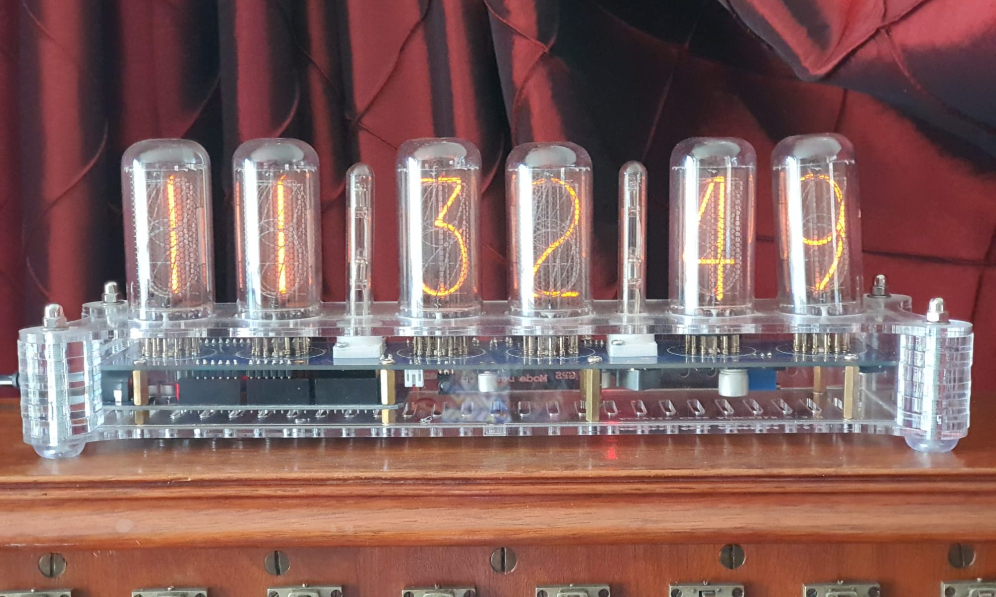
Hiermee synchroniseert de NIXIE klok via een aan te sluiten standaard GPS module met UTC (stond al in de code) en vervolgens met de juiste tijdzone, inclusief automatische verschuiving voor zomer- en wintertijd! (wat geheel nieuw is!)

Zie de werkende versie onder:

Het is nu gecodeerd voor West-Europa en een voorbeeld staat in de code voor een US tijdzone, andere kunnen worden afgeleid uit de voorbeelden die bij de nieuw toegevoegde timezone.lib zitten! #include <Timezone.h>//https://github.com/JChristensen/Timezone

Beschikbare tijdzones:

// Australia Eastern Time Zone (Sydney, Melbourne)
TimeChangeRule aEDT = {“AEDT”, First, Sun, Oct, 2, 660}; // UTC + 11 hours
TimeChangeRule aEST = {“AEST”, First, Sun, Apr, 3, 600}; // UTC + 10 hours
Timezone ausET(aEDT, aEST);

// Moscow Standard Time (MSK, does not observe DST)
TimeChangeRule msk = {“MSK”, Last, Sun, Mar, 1, 180};
Timezone tzMSK(msk);

// Central European Time (Frankfurt, Paris)
TimeChangeRule CEST = {“CEST”, Last, Sun, Mar, 2, 120}; // Central European Summer Time
TimeChangeRule CET = {“CET “, Last, Sun, Oct, 3, 60}; // Central European Standard Time
Timezone CE(CEST, CET);

// United Kingdom (London, Belfast)
TimeChangeRule BST = {“BST”, Last, Sun, Mar, 1, 60}; // British Summer Time
TimeChangeRule GMT = {“GMT”, Last, Sun, Oct, 2, 0}; // Standard Time
Timezone UK(BST, GMT);

// UTC
TimeChangeRule utcRule = {“UTC”, Last, Sun, Mar, 1, 0}; // UTC
Timezone UTC(utcRule);

// US Eastern Time Zone (New York, Detroit)
TimeChangeRule usEDT = {“EDT”, Second, Sun, Mar, 2, -240}; // Eastern Daylight Time = UTC – 4 hours
TimeChangeRule usEST = {“EST”, First, Sun, Nov, 2, -300}; // Eastern Standard Time = UTC – 5 hours
Timezone usET(usEDT, usEST);

// US Central Time Zone (Chicago, Houston)
TimeChangeRule usCDT = {“CDT”, Second, Sun, Mar, 2, -300};
TimeChangeRule usCST = {“CST”, First, Sun, Nov, 2, -360};
Timezone usCT(usCDT, usCST);

// US Mountain Time Zone (Denver, Salt Lake City)
TimeChangeRule usMDT = {“MDT”, Second, Sun, Mar, 2, -360};
TimeChangeRule usMST = {“MST”, First, Sun, Nov, 2, -420};
Timezone usMT(usMDT, usMST);

// Arizona is US Mountain Time Zone but does not use DST
Timezone usAZ(usMST);

// US Pacific Time Zone (Las Vegas, Los Angeles)
TimeChangeRule usPDT = {“PDT”, Second, Sun, Mar, 2, -420};
TimeChangeRule usPST = {“PST”, First, Sun, Nov, 2, -480};
Timezone usPT(usPDT, usPST);

De benodigde arduino libraries staan op de GRA-AFCH Github pagina’s hier:

https://github.com/afch/NixieClock

of download alleen de Libraries

Het werkt echt goed, zie het gezipte bestand hieronder of de arduino code verderop:

NixieClockShield_NCS318_V1_94_TZ.ino

NixieClockShield_NCS318_V1_94_TZ.ino:

const String FirmwareVersion = “0196TZ”;
const char HardwareVersion[] PROGMEM = {“NCS318/568 FW 1.94TZ 2021_04_04 Jantec.nl add-on for Timezones for HW 1.x HV5122 or HV5222”};

//// This ‘TZ’ firmware addition delivers automated Summer/Winter time changes based on your local time zone settings ////
//// Jantec.nl 2023-04-04 The Netherlands, Amsterdam. Please share and re-use! ////
//// This can and may be used in any CLOCK program, with possibly specific minor alteration, due to different libraries and do on ////
//// All of my add-ons are specified in the code! Cheers, Jantec.nl, NL ////
//// The approach here is to automatically change the EEPROM hours setting according to the SUMMER/WINTER timescheme ////
//// meaning: Put in the register: a) the time zone (=normal winter time) versus UTC and b) at the switching times the summer ‘+1’ change versus ‘normal’wintertime ///
//// If the user changes the hours setting, this will be overruled at every programmed time change related to summer/ winter time
//Format _X.XXX_
//NIXIE CLOCK SHIELD NCS318/568 for HW 1.x by GRA & AFCH (fominalec@gmail.com)
//1.94 26.02.2021
//Added: Сhecking the presence of a gps receiver when turned on.
//Return to the previous gps parser
//1.92 21.01.2021
//Added: defines for GPS receiver types
//1.91 29.07.2020
//The driver has been changed to support BOTH HV5122 and HV5222 registers (switching using resistor R5222 Arduino pin No. 8)
//1.90 08.06.2020
//Fixed: GPS timezone issue: added breakTime(now(), tm) to adjustTime function at Time.cpp
//1.89 03.04.2020
//Dots sync with seconds
//1.88 26.03.2020
//GPS synchronization algorithm has been changed (again)
//1.86 23.02.2020
//GPS synchronization algorithm changed
//1.85.3 23.02.2020
//Added: DS3231 internal temperature sensor self test: 5 beeps if fail.
//1.85.2 21.02.2020
//Fixed: Bug with time zones more than +-9
// GPS parser has been replaced by NEOGPS
//1.85.1 05.01.2020
//Value of “HardwareVersion” was changed to NCS318/568
//1.85 14.06.2019
//indication is working inside interrupt (only for Arduino Mega), driver v1.3 is required
//Added: support programmable leds ws2812b
//Some performance optimizations
//1.84 08.04.2018
//LEDs functions moved to external file
//LEDs freezing while music (or sound) played.
//SPI Setup moved driver’s file
//1.83 02.08.2018 (Driver v 1.1 is required)
//Fixed: Temp. reading speed fixed
//Fixed: Dots mixed up (driver was updated to v. 1.1)
//Fixed: RGB LEDs reading from EEPROM
//Fixed: Check for entering data from GPS in range
//1.82 18.07.2018 Dual Date Format
//1.81 18.02.2018 Temp. sensor present analyze
//1.80 06.08.2017
//Added: Date and Time GPS synchronization
//1.70 30.07.2017
//Added IR remote control support (Sony RM-X151) (“MODE”, “UP”, “DOWN”)
//1.60 24_07_2017
//Added: Temperature reading mode in menu and slot machine transaction
//1.0.31 27_04_2017
//Added: antipoisoning effect – slot machine
//1.021 31.01.2017
//Added: time synchronizing each 10 seconds
//Fixed: not correct time reading from RTC while start up
//1.02 17.10.2016
//Fixed: RGB color controls
//Update to Arduino IDE 1.6.12 (Time.h replaced to TimeLib.h)
//1.01
//Added RGB LEDs lock(by UP and Down Buttons)
//Added Down and Up buttons pause and resume self testing
//25.09.2016 update to HW ver 1.1
//25.05.2016

//#define tubes8
#define tubes6
//#define tubes4

#include <SPI.h>
#include <Wire.h>
#include <ClickButton.h>
#include <TimeLib.h>
#ifndef GRA_AND_AFCH_TIME_LIB_MOD
#error The “Time (TimeLib)” library modified by GRA and AFCH must be used!
#endif

//// THIS IS NEW, related to TIMEZONE add-on:
#include <Timezone.h>//https://github.com/JChristensen/Timezone
//Central European Time (Frankfurt, Paris)
TimeChangeRule myDST = {“CEST”, Last, Sun, Mar, 26, 120}; //Central European Summer Time//Daylight time = UTC +2 hours
TimeChangeRule mySTD = {“CET “, Last, Sun, Oct, 3, 60}; //Central European Standard Time (Winter)//Daylight time = UTC +1 hour
Timezone myTZ(myDST, mySTD);
//ADD AND REPLACE THE ABOVE FOR ANY OTHER REQUIRED TIMEZONE FROM THE EXAMPLES IN JChistensen’s exaples folders
// US Eastern Time Zone (New York, Detroit)
//TimeChangeRule myDST = {“EDT”, Second, Sun, Mar, 2, -240}; //Daylight time = UTC – 4 hours
//TimeChangeRule mySTD = {“EST”, First, Sun, Nov, 2, -300}; //Daylight time = UTC – 4 hours
//Timezone myTZ(myDST, mySTD);
TimeChangeRule *tcr; //pointer to the time change rule, use to get the TZ abbrev
time_t utc;
//// end of this add-on for TIMEZONE

#include <Tone.h>
#include <EEPROM.h>
#include “doIndication318_HW1.x.h”
#include <OneWire.h>
//IR remote control /////////// START /////////////////////////////
#if defined(__AVR_ATmega1280__) || defined(__AVR_ATmega2560__)

#define GPS_SYNC_INTERVAL 1800000 // in milliseconds
//#define GPS_SYNC_INTERVAL 180000 //3 minutes
unsigned long Last_Time_GPS_Sync = 0;
//bool GPS_Sync_Flag = false;
//uint32_t GPS_Sync_Interval=120000; // 2 minutes
uint32_t GPS_Sync_Interval = 60000; // first try = 1 minute
uint32_t MillsNow=0;
#define TIME_TO_TRY 60000 //1 minute
bool AttMsgWasShowed=false;

#define GPS_BUFFER_LENGTH 83

char GPS_Package[GPS_BUFFER_LENGTH];
byte GPS_position = 0;

struct GPS_DATE_TIME
{
byte GPS_hours;
byte GPS_minutes;
byte GPS_seconds;
byte GPS_day;
byte GPS_mounth;
int GPS_year;
bool GPS_Valid_Data = false;
unsigned long GPS_Data_Parsed_time;
};

GPS_DATE_TIME GPS_Date_Time;

#define PreZero(digit) ((abs(digit)<10)?”0″+String(abs(digit)):String(abs(digit)))
#include <IRremote.h>
int RECV_PIN = 4;
IRrecv irrecv(RECV_PIN);
decode_results IRresults;
// buttons codes for remote controller Sony RM-X151
#define IR_BUTTON_UP_CODE 0x6621
#define IR_BUTTON_DOWN_CODE 0x2621
#define IR_BUTTON_MODE_CODE 0x7121

class IRButtonState
{
public:
int PAUSE_BETWEEN_PACKETS = 50;
int PACKETS_QTY_IN_LONG_PRESS = 18;

private:
bool Flag = 0;
byte CNT_packets = 0;
unsigned long lastPacketTime = 0;
bool START_TIMER = false;
int _buttonCode;

public: IRButtonState::IRButtonState(int buttonCode)
{
_buttonCode = buttonCode;
}

public: int IRButtonState::checkButtonState(int receivedCode)
{
if (((millis() – lastPacketTime) > PAUSE_BETWEEN_PACKETS) && (START_TIMER == true))
{
START_TIMER = false;
if (CNT_packets >= 2) {
Flag = 0;
CNT_packets = 0;
START_TIMER = false;
return 1;
}
else {
Flag = 0;
CNT_packets = 0;
return 0;
}
}
else
{
if (receivedCode == _buttonCode) { Flag = 1;}
else
{
if (!(Flag == 1)) {return 0;}
else
{
if (!(receivedCode == 0xFFFFFFFF)) {return 0;}
}
}
CNT_packets++;
lastPacketTime = millis();
START_TIMER = true;
if (CNT_packets >= PACKETS_QTY_IN_LONG_PRESS) {
Flag = 0;
CNT_packets = 0;
START_TIMER = false;
return -1;
}
else {return 0;}
}
}
};

IRButtonState IRModeButton(IR_BUTTON_MODE_CODE);
IRButtonState IRUpButton(IR_BUTTON_UP_CODE);
IRButtonState IRDownButton(IR_BUTTON_DOWN_CODE);
#endif

int ModeButtonState = 0;
int UpButtonState = 0;
int DownButtonState = 0;

//IR remote control /////////// START /////////////////////////////

/*#define GPS_BUFFER_LENGTH 83

char GPS_Package[GPS_BUFFER_LENGTH];
byte GPS_position=0;

struct GPS_DATE_TIME
{
byte GPS_hours;
byte GPS_minutes;
byte GPS_seconds;
byte GPS_day;
byte GPS_mounth;
int GPS_year;
bool GPS_Valid_Data=false;
unsigned long GPS_Data_Parsed_time;
};
*/
//GPS_DATE_TIME GPS_Date_Time;

unsigned long GPS_Data_Parsed_time;

boolean UD, LD; // DOTS control;

byte data[12];
byte addr[8];
int celsius, fahrenheit;

#define RedLedPin 9 //MCU WDM output for red LEDs 9-g
#define GreenLedPin 6 //MCU WDM output for green LEDs 6-b
#define BlueLedPin 3 //MCU WDM output for blue LEDs 3-r
#define pinSet A0
#define pinUp A2
#define pinDown A1
//#define pinBuzzer 2
const byte pinBuzzer = 2; // pomenyal
#define pinUpperDots 12 //HIGH value light a dots
#define pinLowerDots 8 //HIGH value light a dots
#define pinTemp 7
bool RTC_present;
#define US_DateFormat 1
#define EU_DateFormat 0
//bool DateFormat=EU_DateFormat;

OneWire ds(pinTemp);
bool TempPresent = false;
#define CELSIUS 0
#define FAHRENHEIT 1

String stringToDisplay = “000000”; // Content of this string will be displayed on tubes (must be 6 chars length)
int menuPosition = 0;
// 0 – time
// 1 – date
// 2 – alarm
// 3 – 12/24 hours mode
// 4 – Temperature
// 5 – TimeZone* (Only for Ardiono Mega)

byte blinkMask = B00000000; //bit mask for blinkin digits (1 – blink, 0 – constant light)
int blankMask = B00000000; //bit mask for digits (1 – off, 0 – on)

byte dotPattern = B00000000; //bit mask for separeting dots (1 – on, 0 – off)
//B10000000 – upper dots
//B01000000 – lower dots

#define DS1307_ADDRESS 0x68
byte zero = 0x00; //workaround for issue #527
int RTC_hours, RTC_minutes, RTC_seconds, RTC_day, RTC_month, RTC_year, RTC_day_of_week;

#define TimeIndex 0
#define DateIndex 1
#define AlarmIndex 2
#define hModeIndex 3
#define TemperatureIndex 4
#define TimeZoneIndex 5
#define TimeHoursIndex 6
#define TimeMintuesIndex 7
#define TimeSecondsIndex 8
#define DateFormatIndex 9
#define DateDayIndex 10
#define DateMonthIndex 11
#define DateYearIndex 12
#define AlarmHourIndex 13
#define AlarmMinuteIndex 14
#define AlarmSecondIndex 15
#define Alarm01 16
#define hModeValueIndex 17
#define DegreesFormatIndex 18
#define HoursOffsetIndex 19

#define FirstParent TimeIndex
#define LastParent TimeZoneIndex
#define SettingsCount (HoursOffsetIndex+1)
#define NoParent 0
#define NoChild 0

//——————————-0——–1——–2——-3——–4——–5——–6——–7——–8——–9———-10——-11———12———13——-14——-15———16———17——–18———-19
// names: Time, Date, Alarm, 12/24, Temperature,TimeZone,hours, mintues, seconds, DateFormat, day, month, year, hour, minute, second alarm01 hour_format Deg.FormIndex HoursOffset
// 1 1 1 1 1 1 1 1 1 1 1 1 1 1 1 1 1 1 1 1
int parent[SettingsCount] = {NoParent, NoParent, NoParent, NoParent,NoParent,NoParent,1, 1, 1, 2, 2, 2, 2, 3, 3, 3, 3, 4, 5, 6};
int firstChild[SettingsCount] = {6, 9, 13, 17, 18, 19, 0, 0, 0, NoChild, 0, 0, 0, 0, 0, 0, 0, 0, 0, 0};
int lastChild[SettingsCount] = { 8, 12, 16, 17, 18, 19, 0, 0, 0, NoChild, 0, 0, 0, 0, 0, 0, 0, 0, 0, 0};
int value[SettingsCount] = { 0, 0, 0, 0, 0, 0, 0, 0, 0, EU_DateFormat, 0, 0, 0, 0, 0, 0, 0, 24, 0, 2};
int maxValue[SettingsCount] = { 0, 0, 0, 0, 0, 0, 23, 59, 59, US_DateFormat, 31, 12, 99, 23, 59, 59, 1, 24, FAHRENHEIT, 14};
int minValue[SettingsCount] = { 0, 0, 0, 12, 0, 0, 00, 00, 00, EU_DateFormat, 1, 1, 00, 00, 00, 00, 0, 12, CELSIUS, -12};
int blinkPattern[SettingsCount] = {
B00000000, //0
B00000000, //1
B00000000, //2
B00000000, //3
B00000000, //4
B00000000, //5
B00000011, //6
B00001100, //7
B00110000, //8
B00111111, //9
B00000011, //10
B00001100, //11
B00110000, //12
B00000011, //13
B00001100, //14
B00110000, //15
B11000000, //16
B00001100, //17
B00111111, //18
B00000011, //19
};

bool editMode = false;

long downTime = 0;
long upTime = 0;
const long settingDelay = 150;
bool BlinkUp = false;
bool BlinkDown = false;
unsigned long enteringEditModeTime = 0;
bool RGBLedsOn = true;
#define RGBLEDsEEPROMAddress 0
#define HourFormatEEPROMAddress 1
#define AlarmTimeEEPROMAddress 2 //3,4,5
#define AlarmArmedEEPROMAddress 6
#define LEDsLockEEPROMAddress 7
#define LEDsRedValueEEPROMAddress 8
#define LEDsGreenValueEEPROMAddress 9
#define LEDsBlueValueEEPROMAddress 10
#define DegreesFormatEEPROMAddress 11
#define HoursOffsetEEPROMAddress 12
#define DateFormatEEPROMAddress 13

//buttons pins declarations
ClickButton setButton(pinSet, LOW, CLICKBTN_PULLUP);
ClickButton upButton(pinUp, LOW, CLICKBTN_PULLUP);
ClickButton downButton(pinDown, LOW, CLICKBTN_PULLUP);
///////////////////

Tone tone1;
#define isdigit(n) (n >= ‘0’ && n <= ‘9’)
//char *song = “MissionImp:d=16,o=6,b=95:32d,32d#,32d,32d#,32d,32d#,32d,32d#,32d,32d,32d#,32e,32f,32f#,32g,g,8p,g,8p,a#,p,c7,p,g,8p,g,8p,f,p,f#,p,g,8p,g,8p,a#,p,c7,p,g,8p,g,8p,f,p,f#,p,a#,g,2d,32p,a#,g,2c#,32p,a#,g,2c,a#5,8c,2p,32p,a#5,g5,2f#,32p,a#5,g5,2f,32p,a#5,g5,2e,d#,8d”;
char *song = “PinkPanther:d=4,o=5,b=160:8d#,8e,2p,8f#,8g,2p,8d#,8e,16p,8f#,8g,16p,8c6,8b,16p,8d#,8e,16p,8b,2a#,2p,16a,16g,16e,16d,2e”;
//char *song=”VanessaMae:d=4,o=6,b=70:32c7,32b,16c7,32g,32p,32g,32p,32d#,32p,32d#,32p,32c,32p,32c,32p,32c7,32b,16c7,32g#,32p,32g#,32p,32f,32p,16f,32c,32p,32c,32p,32c7,32b,16c7,32g,32p,32g,32p,32d#,32p,32d#,32p,32c,32p,32c,32p,32g,32f,32d#,32d,32c,32d,32d#,32c,32d#,32f,16g,8p,16d7,32c7,32d7,32a#,32d7,32a,32d7,32g,32d7,32d7,32p,32d7,32p,32d7,32p,16d7,32c7,32d7,32a#,32d7,32a,32d7,32g,32d7,32d7,32p,32d7,32p,32d7,32p,32g,32f,32d#,32d,32c,32d,32d#,32c,32d#,32f,16c”;
//char *song=”DasBoot:d=4,o=5,b=100:d#.4,8d4,8c4,8d4,8d#4,8g4,a#.4,8a4,8g4,8a4,8a#4,8d,2f.,p,f.4,8e4,8d4,8e4,8f4,8a4,c.,8b4,8a4,8b4,8c,8e,2g.,2p”;
//char *song=”Scatman:d=4,o=5,b=200:8b,16b,32p,8b,16b,32p,8b,2d6,16p,16c#.6,16p.,8d6,16p,16c#6,8b,16p,8f#,2p.,16c#6,8p,16d.6,16p.,16c#6,16b,8p,8f#,2p,32p,2d6,16p,16c#6,8p,16d.6,16p.,16c#6,16a.,16p.,8e,2p.,16c#6,8p,16d.6,16p.,16c#6,16b,8p,8b,16b,32p,8b,16b,32p,8b,2d6,16p,16c#.6,16p.,8d6,16p,16c#6,8b,16p,8f#,2p.,16c#6,8p,16d.6,16p.,16c#6,16b,8p,8f#,2p,32p,2d6,16p,16c#6,8p,16d.6,16p.,16c#6,16a.,16p.,8e,2p.,16c#6,8p,16d.6,16p.,16c#6,16a,8p,8e,2p,32p,16f#.6,16p.,16b.,16p.”;
//char *song=”Popcorn:d=4,o=5,b=160:8c6,8a#,8c6,8g,8d#,8g,c,8c6,8a#,8c6,8g,8d#,8g,c,8c6,8d6,8d#6,16c6,8d#6,16c6,8d#6,8d6,16a#,8d6,16a#,8d6,8c6,8a#,8g,8a#,c6″;
//char *song=”WeWishYou:d=4,o=5,b=200:d,g,8g,8a,8g,8f#,e,e,e,a,8a,8b,8a,8g,f#,d,d,b,8b,8c6,8b,8a,g,e,d,e,a,f#,2g,d,g,8g,8a,8g,8f#,e,e,e,a,8a,8b,8a,8g,f#,d,d,b,8b,8c6,8b,8a,g,e,d,e,a,f#,1g,d,g,g,g,2f#,f#,g,f#,e,2d,a,b,8a,8a,8g,8g,d6,d,d,e,a,f#,2g”;
#define OCTAVE_OFFSET 0
char *p;

int notes[] = { 0,
NOTE_C4, NOTE_CS4, NOTE_D4, NOTE_DS4, NOTE_E4, NOTE_F4, NOTE_FS4, NOTE_G4, NOTE_GS4, NOTE_A4, NOTE_AS4, NOTE_B4,
NOTE_C5, NOTE_CS5, NOTE_D5, NOTE_DS5, NOTE_E5, NOTE_F5, NOTE_FS5, NOTE_G5, NOTE_GS5, NOTE_A5, NOTE_AS5, NOTE_B5,
NOTE_C6, NOTE_CS6, NOTE_D6, NOTE_DS6, NOTE_E6, NOTE_F6, NOTE_FS6, NOTE_G6, NOTE_GS6, NOTE_A6, NOTE_AS6, NOTE_B6,
NOTE_C7, NOTE_CS7, NOTE_D7, NOTE_DS7, NOTE_E7, NOTE_F7, NOTE_FS7, NOTE_G7, NOTE_GS7, NOTE_A7, NOTE_AS7, NOTE_B7
};

int fireforks[] = {0, 0, 1, //1
-1, 0, 0, //2
0, 1, 0, //3
0, 0, -1, //4
1, 0, 0, //5
0, -1, 0
}; //array with RGB rules (0 – do nothing, -1 – decrese, +1 – increse

void setRTCDateTime(byte h, byte m, byte s, byte d, byte mon, byte y, byte w = 1);

int functionDownButton = 0;
int functionUpButton = 0;
bool LEDsLock = false;

//antipoisoning transaction
bool modeChangedByUser = false;
bool transactionInProgress = false; //antipoisoning transaction
#define timeModePeriod 60000
#define dateModePeriod 5000
long modesChangePeriod = timeModePeriod;
//end of antipoisoning transaction

bool GPS_sync_flag=false;

extern const int LEDsDelay;

/*******************************************************************************************************
Init Programm
*******************************************************************************************************/
void setup()
{
Wire.begin();
//setRTCDateTime(23,40,00,25,7,15,1);

Serial.begin(115200);
#if defined(__AVR_ATmega1280__) || defined(__AVR_ATmega2560__)
Serial1.begin(9600);
digitalWrite(19, HIGH);
#endif


if (EEPROM.read(HourFormatEEPROMAddress) != 12) value[hModeValueIndex] = 24; else value[hModeValueIndex] = 12;
if (EEPROM.read(RGBLEDsEEPROMAddress) != 0) RGBLedsOn = true; else RGBLedsOn = false;
if (EEPROM.read(AlarmTimeEEPROMAddress) == 255) value[AlarmHourIndex] = 0; else value[AlarmHourIndex] = EEPROM.read(AlarmTimeEEPROMAddress);
if (EEPROM.read(AlarmTimeEEPROMAddress + 1) == 255) value[AlarmMinuteIndex] = 0; else value[AlarmMinuteIndex] = EEPROM.read(AlarmTimeEEPROMAddress + 1);
if (EEPROM.read(AlarmTimeEEPROMAddress + 2) == 255) value[AlarmSecondIndex] = 0; else value[AlarmSecondIndex] = EEPROM.read(AlarmTimeEEPROMAddress + 2);
if (EEPROM.read(AlarmArmedEEPROMAddress) == 255) value[Alarm01] = 0; else value[Alarm01] = EEPROM.read(AlarmArmedEEPROMAddress);
if (EEPROM.read(LEDsLockEEPROMAddress) == 255) LEDsLock = false; else LEDsLock = EEPROM.read(LEDsLockEEPROMAddress);
if (EEPROM.read(DegreesFormatEEPROMAddress) == 255) value[DegreesFormatIndex] = CELSIUS; else value[DegreesFormatIndex] = EEPROM.read(DegreesFormatEEPROMAddress);
if (EEPROM.read(HoursOffsetEEPROMAddress) == 255) value[HoursOffsetIndex] = value[HoursOffsetIndex]; else value[HoursOffsetIndex] = EEPROM.read(HoursOffsetEEPROMAddress) + minValue[HoursOffsetIndex];

//// needed to set this HoursOffsetIndex variable to 0 since we will use the timezone lib (local timezone and summer/winter time add-ons by Jantec.nl)
value[HoursOffsetIndex] = 0;
EEPROM.write(HoursOffsetEEPROMAddress, 0);

if (EEPROM.read(DateFormatEEPROMAddress) == 255) value[DateFormatIndex] = value[DateFormatIndex]; else value[DateFormatIndex] = EEPROM.read(DateFormatEEPROMAddress);

//Serial.print(F(“led lock=”));
//Serial.println(LEDsLock);

pinMode(RedLedPin, OUTPUT);
pinMode(GreenLedPin, OUTPUT);
pinMode(BlueLedPin, OUTPUT);

tone1.begin(pinBuzzer);
song = parseSong(song);

pinMode(LEpin, OUTPUT);

// SPI setup
SPISetup();
LEDsSetup();
//buttons pins inits
pinMode(pinSet, INPUT_PULLUP);
pinMode(pinUp, INPUT_PULLUP);
pinMode(pinDown, INPUT_PULLUP);
////////////////////////////
pinMode(pinBuzzer, OUTPUT);

//buttons objects inits
setButton.debounceTime = 20; // Debounce timer in ms
setButton.multiclickTime = 30; // Time limit for multi clicks
setButton.longClickTime = 2000; // time until “held-down clicks” register

upButton.debounceTime = 20; // Debounce timer in ms
upButton.multiclickTime = 30; // Time limit for multi clicks
upButton.longClickTime = 2000; // time until “held-down clicks” register

downButton.debounceTime = 20; // Debounce timer in ms
downButton.multiclickTime = 30; // Time limit for multi clicks
downButton.longClickTime = 2000; // time until “held-down clicks” register

#if defined(__AVR_ATmega1280__) || defined(__AVR_ATmega2560__)
timerSetup();
#endif
//!!!!!!!!!!!!!!!!!!!!!!!!!!!!!!!!!!!!!!!!!!!!!!!!
doTest();
//!!!!!!!!!!!!!!!!!!!!!!!!!!!!!!!!!!!!!!!!!!!!!!!
if (LEDsLock == 1)
{
setLEDsFromEEPROM();
}
getRTCTime();
byte prevSeconds = RTC_seconds;
unsigned long RTC_ReadingStartTime = millis();
RTC_present = true;
while (prevSeconds == RTC_seconds)
{
getRTCTime();
//Serial.println(RTC_seconds);
if ((millis() – RTC_ReadingStartTime) > 3000)
{
#ifdef DEBUG
Serial.println(F(“Warning! RTC DON’T RESPOND!”));
#endif
RTC_present = false;
break;
}
}
setTime(RTC_hours, RTC_minutes, RTC_seconds, RTC_day, RTC_month, RTC_year);

#if defined(__AVR_ATmega1280__) || defined(__AVR_ATmega2560__)
irrecv.blink13(false);
irrecv.enableIRIn(); // Start the receiver
#endif

//// add-ons for TIMEZONE
time_t utc = now();
time_t local = myTZ.toLocal(utc, &tcr);
Serial.println();
printDateTime(utc, “UTC”);
printDateTime(local, tcr -> abbrev);
delay(1000);//was 10000
//// end of add-ons for TIMEZONE

}

int rotator = 0; //index in array with RGB “rules” (increse by one on each 255 cycles)
int cycle = 0; //cycles counter
int RedLight = 255;
int GreenLight = 0;
int BlueLight = 0;
unsigned long prevTime = 0; // time of lase tube was lit
unsigned long prevTime4FireWorks = 0; //time of last RGB changed
//int minuteL=0; //младшая цифра минут

/***************************************************************************************************************
MAIN Programm
***************************************************************************************************************/
void loop() {

if (((millis() % 10000) == 0) && (RTC_present)) //synchronize with RTC every 10 seconds
{
getRTCTime();

setTime(RTC_hours, RTC_minutes, RTC_seconds, RTC_day, RTC_month, RTC_year);
// 4 lines of time zone & winter/summer time additions by Jantec.nl 2023 0404
time_t utc = now();
time_t local = myTZ.toLocal(utc, &tcr);
setTime(myTZ.toLocal(utc, &tcr));
EEPROM.write(DateFormatEEPROMAddress, value[myTZ.toLocal(utc, &tcr)]);

//Serial.println(F(“Sync”));
}

#if defined(__AVR_ATmega1280__) || defined(__AVR_ATmega2560__)

MillsNow=millis();
if ((MillsNow – Last_Time_GPS_Sync) > GPS_Sync_Interval)
{
//GPS_Sync_Interval = GPS_SYNC_INTERVAL; // <—-!
//GPS_Sync_Flag = 0;
if (AttMsgWasShowed==false)
{
Serial.println(F(“Attempt to sync with GPS.”));
AttMsgWasShowed=true;
}
GetDataFromSerial1();
//SyncWithGPS();
}
if ((MillsNow – Last_Time_GPS_Sync) > GPS_Sync_Interval + TIME_TO_TRY)
{
Last_Time_GPS_Sync=MillsNow; //if it is not possible to synchronize within the allotted time TIME_TO_TRY, then we postpone attempts to the next time interval.
//GPS_Sync_Flag = 1;
//GPS_Sync_Interval = GPS_SYNC_INTERVAL;
Serial.println(F(“All attempts were unsuccessful.”));
AttMsgWasShowed=false;
}

IRresults.value = 0;
if (irrecv.decode(&IRresults)) {
Serial.println(IRresults.value, HEX);
irrecv.resume(); // Receive the next value
}

ModeButtonState = IRModeButton.checkButtonState(IRresults.value);
if (ModeButtonState == 1) Serial.println(F(“Mode short”));
if (ModeButtonState == -1) Serial.println(F(“Mode long….”));

UpButtonState = IRUpButton.checkButtonState(IRresults.value);
if (UpButtonState == 1) Serial.println(F(“Up short”));
if (UpButtonState == -1) Serial.println(F(“Up long….”));

DownButtonState = IRDownButton.checkButtonState(IRresults.value);
if (DownButtonState == 1) Serial.println(F(“Down short”));
if (DownButtonState == -1) Serial.println(F(“Down long….”));

#else
ModeButtonState=0;
UpButtonState=0;
DownButtonState=0;
#endif

p = playmusic(p);

if ((millis() – prevTime4FireWorks) > LEDsDelay)
{
rotateFireWorks(); //change color (by 1 step)
prevTime4FireWorks = millis();
}

if ((menuPosition == TimeIndex) || (modeChangedByUser == false) ) modesChanger();
#if defined (__AVR_ATmega328P__)
doIndication();
#endif

setButton.Update();
upButton.Update();
downButton.Update();
if (editMode == false)
{
blinkMask = B00000000;

} else if ((millis() – enteringEditModeTime) > 60000)
{
editMode = false;
menuPosition = firstChild[menuPosition];
blinkMask = blinkPattern[menuPosition];
}
if ((setButton.clicks > 0) || (ModeButtonState == 1)) //short click
{
modeChangedByUser = true;
p = 0; //shut off music )))
tone1.play(1000, 100);
enteringEditModeTime = millis();
/*if (value[DateFormatIndex] == US_DateFormat)
{
//if (menuPosition == )
} else */
menuPosition = menuPosition + 1;
#if defined (__AVR_ATmega328P__)
if (menuPosition == TimeZoneIndex) menuPosition++;// skip TimeZone for Arduino Uno
#endif
if (menuPosition == LastParent + 1) menuPosition = TimeIndex;
/*Serial.print(F(“menuPosition=”));
Serial.println(menuPosition);
Serial.print(F(“value=”));
Serial.println(value[menuPosition]);*/

blinkMask = blinkPattern[menuPosition];
if ((parent[menuPosition – 1] != 0) and (lastChild[parent[menuPosition – 1] – 1] == (menuPosition – 1))) //exit from edit mode
{
if ((parent[menuPosition – 1] – 1 == 1) && (!isValidDate()))
{
menuPosition = DateDayIndex;
return;
}
editMode = false;
menuPosition = parent[menuPosition – 1] – 1;
if (menuPosition == TimeIndex) setTime(value[TimeHoursIndex], value[TimeMintuesIndex], value[TimeSecondsIndex], day(), month(), year());
if (menuPosition == DateIndex)
{
#ifdef DEBUG
Serial.print(F(“Day:”));
Serial.println(value[DateDayIndex]);
Serial.print(F(“Month:”));
Serial.println(value[DateMonthIndex]);
#endif
setTime(hour(), minute(), second(), value[DateDayIndex], value[DateMonthIndex], 2000 + value[DateYearIndex]);
EEPROM.write(DateFormatEEPROMAddress, value[DateFormatIndex]);
}
if (menuPosition == AlarmIndex) {
EEPROM.write(AlarmTimeEEPROMAddress, value[AlarmHourIndex]);
EEPROM.write(AlarmTimeEEPROMAddress + 1, value[AlarmMinuteIndex]);
EEPROM.write(AlarmTimeEEPROMAddress + 2, value[AlarmSecondIndex]);
EEPROM.write(AlarmArmedEEPROMAddress, value[Alarm01]);
};
if (menuPosition == hModeIndex) EEPROM.write(HourFormatEEPROMAddress, value[hModeValueIndex]);
if (menuPosition == TemperatureIndex)
{
EEPROM.write(DegreesFormatEEPROMAddress, value[DegreesFormatIndex]);
}
if (menuPosition == TimeZoneIndex) EEPROM.write(HoursOffsetEEPROMAddress, value[HoursOffsetIndex] – minValue[HoursOffsetIndex]);
//if (menuPosition == hModeIndex) EEPROM.write(HourFormatEEPROMAddress, value[hModeValueIndex]);
setRTCDateTime(hour(), minute(), second(), day(), month(), year() % 1000, 1);
return;
} //end exit from edit mode
/*Serial.print(“menu pos=”);
Serial.println(menuPosition);
Serial.print(“DateFormat”);
Serial.println(value[DateFormatIndex]);*/
if ((menuPosition != HoursOffsetIndex) &&
(menuPosition != DateFormatIndex) &&
(menuPosition != DateDayIndex)) value[menuPosition] = extractDigits(blinkMask);
}
if ((setButton.clicks < 0) || (ModeButtonState == -1)) //long click
{
tone1.play(1000, 100);
if (!editMode)
{
enteringEditModeTime = millis();
if (menuPosition == TimeIndex) stringToDisplay = PreZero(hour()) + PreZero(minute()) + PreZero(second()); //temporary enabled 24 hour format while settings
}
if (menuPosition == DateIndex)
{
// Serial.println(“DateEdit”);
value[DateDayIndex] = day();
value[DateMonthIndex] = month();
value[DateYearIndex] = year() % 1000;
if (value[DateFormatIndex] == EU_DateFormat) stringToDisplay=PreZero(value[DateDayIndex])+PreZero(value[DateMonthIndex])+PreZero(value[DateYearIndex]);
else stringToDisplay=PreZero(value[DateMonthIndex])+PreZero(value[DateDayIndex])+PreZero(value[DateYearIndex]);
//Serial.print(“str=”);
// Serial.println(stringToDisplay);
}
menuPosition = firstChild[menuPosition];
if (menuPosition == AlarmHourIndex) {
value[Alarm01] = 1; /*digitalWrite(pinUpperDots, HIGH);*/dotPattern = B10000000;
}
editMode = !editMode;
blinkMask = blinkPattern[menuPosition];
if ((menuPosition != DegreesFormatIndex) &&
(menuPosition != HoursOffsetIndex) &&
(menuPosition != DateFormatIndex))
value[menuPosition] = extractDigits(blinkMask);
/*Serial.print(F(“menuPosition=”));
Serial.println(menuPosition);
Serial.print(F(“value=”));
Serial.println(value[menuPosition]); */
}

if (upButton.clicks != 0) functionUpButton = upButton.clicks;

if ((upButton.clicks > 0) || (UpButtonState == 1))
{
modeChangedByUser = true;
p = 0; //shut off music )))
tone1.play(1000, 100);
incrementValue();
if (!editMode)
{
LEDsLock = false;
EEPROM.write(LEDsLockEEPROMAddress, 0);
}
}

if (functionUpButton == -1 && upButton.depressed == true)
{
BlinkUp = false;
if (editMode == true)
{
if ( (millis() – upTime) > settingDelay)
{
upTime = millis();// + settingDelay;
incrementValue();
}
}
} else BlinkUp = true;

if (downButton.clicks != 0) functionDownButton = downButton.clicks;

if ((downButton.clicks > 0) || (DownButtonState == 1))
{
modeChangedByUser = true;
p = 0; //shut off music )))
tone1.play(1000, 100);
dicrementValue();
if (!editMode)
{
LEDsLock = true;
EEPROM.write(LEDsLockEEPROMAddress, 1);
EEPROM.write(LEDsRedValueEEPROMAddress, RedLight);
EEPROM.write(LEDsGreenValueEEPROMAddress, GreenLight);
EEPROM.write(LEDsBlueValueEEPROMAddress, BlueLight);
/*Serial.println(F(“Store to EEPROM:”));
Serial.print(F(“RED=”));
Serial.println(RedLight);
Serial.print(F(“GREEN=”));
Serial.println(GreenLight);
Serial.print(F(“Blue=”));
Serial.println(BlueLight);*/
}
}

if (functionDownButton == -1 && downButton.depressed == true)
{
BlinkDown = false;
if (editMode == true)
{
if ( (millis() – downTime) > settingDelay)
{
downTime = millis();// + settingDelay;
dicrementValue();
}
}
} else BlinkDown = true;

if (!editMode)
{
if ((upButton.clicks < 0) || (UpButtonState == -1))
{
tone1.play(1000, 100);
RGBLedsOn = true;
EEPROM.write(RGBLEDsEEPROMAddress, 1);
#ifdef DEBUG
Serial.println(F(“RGB=on”));
#endif
setLEDsFromEEPROM();
}
if ((downButton.clicks < 0) || (DownButtonState == -1))
{
tone1.play(1000, 100);
RGBLedsOn = false;
EEPROM.write(RGBLEDsEEPROMAddress, 0);
#ifdef DEBUG
Serial.println(F(“RGB=off”));
#endif
}
}

static bool updateDateTime = false;
float curTemp=0;
switch (menuPosition)
{
case TimeIndex: //time mode
if (!transactionInProgress) stringToDisplay = updateDisplayString();
doDotBlink();
checkAlarmTime();
blankMask = B00000000;
break;
case DateIndex: //date mode
if (!transactionInProgress) stringToDisplay = updateDateString();
dotPattern = B01000000; //turn on lower dots
checkAlarmTime();
blankMask = B00000000;
break;
case AlarmIndex: //alarm mode
//stringToDisplay=”000000″;
//unsigned long execTime;
//execTime=micros();
stringToDisplay = PreZero(value[AlarmHourIndex]) + PreZero(value[AlarmMinuteIndex]) + PreZero(value[AlarmSecondIndex]);
blankMask = B00000000;
if (value[Alarm01] == 1) dotPattern = B10000000; //turn on upper dots
else
{
dotPattern = B00000000; //turn off upper dots
}
//execTime=micros()-execTime;
//Serial.println(execTime);
checkAlarmTime();
break;
case hModeIndex: //12/24 hours mode
stringToDisplay = “00” + String(value[hModeValueIndex]) + “00”;
blankMask = B00110011;
dotPattern = B00000000; //turn off all dots
checkAlarmTime();
break;
case TemperatureIndex: //missed break
case DegreesFormatIndex:

if (!transactionInProgress)
{
curTemp=getTemperature(value[DegreesFormatIndex]);
stringToDisplay = updateTemperatureString(curTemp);
if (value[DegreesFormatIndex] == CELSIUS)
{
blankMask = B00110001;
dotPattern = B01000000;
}
else
{
blankMask = B00100011;
dotPattern = B00000000;
}
}

if (curTemp < 0) dotPattern |= B10000000;
else dotPattern &= B01111111;
break;
case TimeZoneIndex:
case HoursOffsetIndex:
stringToDisplay = String(PreZero(value[HoursOffsetIndex])) + “0000”;
blankMask = B00001111;
if (value[HoursOffsetIndex]>=0) dotPattern = B00000000; //turn off all dots
else dotPattern = B10000000; //turn on upper dots
break;
case DateFormatIndex:
if (value[DateFormatIndex] == EU_DateFormat)
{
stringToDisplay=”311299″;
blinkPattern[DateDayIndex]=B00000011;
blinkPattern[DateMonthIndex]=B00001100;
}
else
{
stringToDisplay=”123199″;
blinkPattern[DateDayIndex]=B00001100;
blinkPattern[DateMonthIndex]=B00000011;
}
break;
case DateDayIndex:
case DateMonthIndex:
case DateYearIndex:
if (value[DateFormatIndex] == EU_DateFormat) stringToDisplay=PreZero(value[DateDayIndex])+PreZero(value[DateMonthIndex])+PreZero(value[DateYearIndex]);
else stringToDisplay=PreZero(value[DateMonthIndex])+PreZero(value[DateDayIndex])+PreZero(value[DateYearIndex]);
break;
}
// IRresults.value=0;
}
#if defined (__AVR_ATmega328P__)
String PreZero(int digit)
{
digit=abs(digit);
if (digit < 10) return String(“0”) + String(digit);
//if (digit < 10) return “0” + String(digit);
else return String(digit);
}
#endif

String updateDisplayString()
{
static int prevS=-1;

if (second()!=prevS)
{
prevS=second();
return getTimeNow();
} else return stringToDisplay;
}

String getTimeNow()
{
if (value[hModeValueIndex] == 24) return PreZero(hour()) + PreZero(minute()) + PreZero(second());
else return PreZero(hourFormat12()) + PreZero(minute()) + PreZero(second());
}
//// add-on void for TIMEZONE ////////////////////////////////////////////////////////////
// format and print a time_t value, with a time zone appended.
void printDateTime(time_t t, const char *tz)
{
char buf[32];
char m[4]; // temporary storage for month string (DateStrings.cpp uses shared buffer)
strcpy(m, monthShortStr(month(t)));
sprintf(buf, “%.2d:%.2d:%.2d %s %.2d %s %d %s”,
hour(t), minute(t), second(t), dayShortStr(weekday(t)), day(t), m, year(t), tz);
Serial.println(buf);
}
/////// Jantec.nl 2023-04-04 The Netherlands, Amsterdam. Please share and re-use! ////////
void doTest()
{
Serial.print(F(“Firmware version: “));
Serial.println(FirmwareVersion.substring(1,2)+”.”+FirmwareVersion.substring(2,5));
for (byte k = 0; k < strlen_P(HardwareVersion); k++) {
Serial.print((char)pgm_read_byte_near(HardwareVersion + k));
}
Serial.println();
#ifdef DEBUG
Serial.println(F(“Start Test”));
#endif

p=song;
parseSong(p);
//p=0; //need to be deleted

LEDsTest();
#if defined(__AVR_ATmega1280__) || defined(__AVR_ATmega2560__)
if (Serial1.available() > 20) Serial.println(F(“GPS detected”));
else Serial.println(F(“GPS NOT detected!”));
#endif

#ifdef tubes8
String testStringArray[11]={“00000000″,”11111111″,”22222222″,”33333333″,”44444444″,”55555555″,”66666666″,”77777777″,”88888888″,”99999999″,””};
testStringArray[10]=FirmwareVersion+”00″;
#endif
#ifdef tubes6
String testStringArray[11]={“000000″,”111111″,”222222″,”333333″,”444444″,”555555″,”666666″,”777777″,”888888″,”999999″,””};
testStringArray[10]=FirmwareVersion;
#endif

int dlay=500;
bool test=1;
byte strIndex=-1;
unsigned long startOfTest=millis()+1000; //disable delaying in first iteration
bool digitsLock=false;
while (test)
{
if (digitalRead(pinDown)==0) digitsLock=true;
if (digitalRead(pinUp)==0) digitsLock=false;

if ((millis()-startOfTest)>dlay)
{
startOfTest=millis();
if (!digitsLock) strIndex=strIndex+1;
if (strIndex==10) dlay=2000;
if (strIndex>10) { test=false; strIndex=10;}

stringToDisplay=testStringArray[strIndex];
#ifdef DEBUG
Serial.println(stringToDisplay);
#endif
}
#if defined (__AVR_ATmega328P__)
doIndication();
#endif
}

if ( !ds.search(addr))
{
#ifdef DEBUG
Serial.println(F(“Temp. sensor not found.”));
#endif
} else TempPresent=true;

testDS3231TempSensor();

#ifdef DEBUG
Serial.println(F(“Stop Test”));
#endif
// while(1);
}

void doDotBlink()
{
if (second()%2 == 0) dotPattern = B11000000;
else dotPattern = B00000000;
}

void setRTCDateTime(byte h, byte m, byte s, byte d, byte mon, byte y, byte w)
{
Wire.beginTransmission(DS1307_ADDRESS);
Wire.write(zero); //stop Oscillator

Wire.write(decToBcd(s));
Wire.write(decToBcd(m));
Wire.write(decToBcd(h));
Wire.write(decToBcd(w));
Wire.write(decToBcd(d));
Wire.write(decToBcd(mon));
Wire.write(decToBcd(y));

Wire.write(zero); //start

Wire.endTransmission();

}

byte decToBcd(byte val) {
// Convert normal decimal numbers to binary coded decimal
return ( (val / 10 * 16) + (val % 10) );
}

byte bcdToDec(byte val) {
// Convert binary coded decimal to normal decimal numbers
return ( (val / 16 * 10) + (val % 16) );
}

void getRTCTime()
{
Wire.beginTransmission(DS1307_ADDRESS);
Wire.write(zero);
Wire.endTransmission();

Wire.requestFrom(DS1307_ADDRESS, 7);

RTC_seconds = bcdToDec(Wire.read());
RTC_minutes = bcdToDec(Wire.read());
RTC_hours = bcdToDec(Wire.read() & 0b111111); //24 hour time
RTC_day_of_week = bcdToDec(Wire.read()); //0-6 -> sunday – Saturday
RTC_day = bcdToDec(Wire.read());
RTC_month = bcdToDec(Wire.read());
RTC_year = bcdToDec(Wire.read());
}

int extractDigits(byte b)
{
String tmp = “1”;

if (b == B00000011)
{
tmp = stringToDisplay.substring(0, 2);
}
if (b == B00001100)
{
tmp = stringToDisplay.substring(2, 4);
}
if (b == B00110000)
{
tmp = stringToDisplay.substring(4);
}
return tmp.toInt();
}

void injectDigits(byte b, int value)
{
if (b == B00000011) stringToDisplay = PreZero(value) + stringToDisplay.substring(2);
if (b == B00001100) stringToDisplay = stringToDisplay.substring(0, 2) + PreZero(value) + stringToDisplay.substring(4);
if (b == B00110000) stringToDisplay = stringToDisplay.substring(0, 4) + PreZero(value);
}

bool isValidDate()
{
int days[12] = {31, 28, 31, 30, 31, 30, 31, 31, 30, 31, 30, 31};
if (value[DateYearIndex] % 4 == 0) days[1] = 29;
if (value[DateDayIndex] > days[value[DateMonthIndex] – 1]) return false;
else return true;

}

byte default_dur = 4;
byte default_oct = 6;
int bpm = 63;
int num;
long wholenote;
long duration;
byte note;
byte scale;
char* parseSong(char *p)
{
// Absolutely no error checking in here
// format: d=N,o=N,b=NNN:
// find the start (skip name, etc)

while (*p != ‘:’) p++; // ignore name
p++; // skip ‘:’

// get default duration
if (*p == ‘d’)
{
p++; p++; // skip “d=”
num = 0;
while (isdigit(*p))
{
num = (num * 10) + (*p++ – ‘0’);
}
if (num > 0) default_dur = num;
p++; // skip comma
}

// get default octave
if (*p == ‘o’)
{
p++; p++; // skip “o=”
num = *p++ – ‘0’;
if (num >= 3 && num <= 7) default_oct = num;
p++; // skip comma
}

// get BPM
if (*p == ‘b’)
{
p++; p++; // skip “b=”
num = 0;
while (isdigit(*p))
{
num = (num * 10) + (*p++ – ‘0’);
}
bpm = num;
p++; // skip colon
}

// BPM usually expresses the number of quarter notes per minute
wholenote = (60 * 1000L / bpm) * 4; // this is the time for whole note (in milliseconds)
return p;
}

// now begin note loop
static unsigned long lastTimeNotePlaying = 0;
char* playmusic(char *p)
{
if (*p == 0)
{
return p;
}
if (millis() – lastTimeNotePlaying > duration)
lastTimeNotePlaying = millis();
else return p;
// first, get note duration, if available
num = 0;
while (isdigit(*p))
{
num = (num * 10) + (*p++ – ‘0’);
}

if (num) duration = wholenote / num;
else duration = wholenote / default_dur; // we will need to check if we are a dotted note after

// now get the note
note = 0;

switch (*p)
{
case ‘c’:
note = 1;
break;
case ‘d’:
note = 3;
break;
case ‘e’:
note = 5;
break;
case ‘f’:
note = 6;
break;
case ‘g’:
note = 8;
break;
case ‘a’:
note = 10;
break;
case ‘b’:
note = 12;
break;
case ‘p’:
default:
note = 0;
}
p++;

// now, get optional ‘#’ sharp
if (*p == ‘#’)
{
note++;
p++;
}

// now, get optional ‘.’ dotted note
if (*p == ‘.’)
{
duration += duration / 2;
p++;
}

// now, get scale
if (isdigit(*p))
{
scale = *p – ‘0’;
p++;
}
else
{
scale = default_oct;
}

scale += OCTAVE_OFFSET;

if (*p == ‘,’)
p++; // skip comma for next note (or we may be at the end)

// now play the note

if (note)
{
tone1.play(notes[(scale – 4) * 12 + note], duration);
if (millis() – lastTimeNotePlaying > duration)
lastTimeNotePlaying = millis();
else return p;
tone1.stop();
}
else
{
return p;
}
#ifdef DEBUG
Serial.println(F(“Incorrect Song Format!”));
#endif
return 0; //error
}

void incrementValue()
{
enteringEditModeTime = millis();
if (editMode == true)
{
if (menuPosition != hModeValueIndex) // 12/24 hour mode menu position
value[menuPosition] = value[menuPosition] + 1; else value[menuPosition] = value[menuPosition] + 12;
if (value[menuPosition] > maxValue[menuPosition]) value[menuPosition] = minValue[menuPosition];
if (menuPosition == Alarm01)
{
if (value[menuPosition] == 1) /*digitalWrite(pinUpperDots, HIGH);*/dotPattern = B10000000; //turn on upper dots
/*else digitalWrite(pinUpperDots, LOW); */ dotPattern = B00000000; //turn off all dots
}
if (menuPosition!=DateFormatIndex) injectDigits(blinkMask, value[menuPosition]);
/*Serial.print(“value=”);
Serial.println(value[menuPosition]);*/
}
}

void dicrementValue()
{
enteringEditModeTime = millis();
if (editMode == true)
{
if (menuPosition != hModeValueIndex) value[menuPosition] = value[menuPosition] – 1; else value[menuPosition] = value[menuPosition] – 12;
if (value[menuPosition] < minValue[menuPosition]) value[menuPosition] = maxValue[menuPosition];
if (menuPosition == Alarm01)
{
if (value[menuPosition] == 1) /*digitalWrite(pinUpperDots, HIGH);*/ dotPattern = B10000000; //turn on upper dots
else /*digitalWrite(pinUpperDots, LOW);*/ dotPattern = B00000000; //turn off all dots
}
if (menuPosition!=DateFormatIndex) injectDigits(blinkMask, value[menuPosition]);
/*Serial.print(“value=”);
Serial.println(value[menuPosition]);*/
}
}

bool Alarm1SecondBlock = false;
unsigned long lastTimeAlarmTriggired = 0;
void checkAlarmTime()
{
if (value[Alarm01] == 0) return;
if ((Alarm1SecondBlock == true) && ((millis() – lastTimeAlarmTriggired) > 1000)) Alarm1SecondBlock = false;
if (Alarm1SecondBlock == true) return;
if ((hour() == value[AlarmHourIndex]) && (minute() == value[AlarmMinuteIndex]) && (second() == value[AlarmSecondIndex]))
{
lastTimeAlarmTriggired = millis();
Alarm1SecondBlock = true;
#ifdef DEBUG
Serial.println(F(“Wake up, Neo!”));
#endif
p = song;
}
}

void modesChanger()
{
if (editMode == true) return;
static unsigned long lastTimeModeChanged = millis();
static unsigned long lastTimeAntiPoisoningIterate = millis();
static int transnumber = 0;
if ((millis() – lastTimeModeChanged) > modesChangePeriod)
{
lastTimeModeChanged = millis();
if (transnumber == 0) {
menuPosition = DateIndex;
modesChangePeriod = dateModePeriod;
}
if (transnumber == 1) {
menuPosition = TemperatureIndex;
modesChangePeriod = dateModePeriod;
if (!TempPresent) transnumber = 2;
}
if (transnumber == 2) {
menuPosition = TimeIndex;
modesChangePeriod = timeModePeriod;
}
transnumber++;
if (transnumber > 2) transnumber = 0;

if (modeChangedByUser == true)
{
menuPosition = TimeIndex;
}
modeChangedByUser = false;
}
if ((millis() – lastTimeModeChanged) < 2000)
{
if ((millis() – lastTimeAntiPoisoningIterate) > 100)
{
lastTimeAntiPoisoningIterate = millis();
if (TempPresent)
{
if (menuPosition == TimeIndex) stringToDisplay = antiPoisoning2(updateTemperatureString(getTemperature(value[DegreesFormatIndex])), getTimeNow());
if (menuPosition == DateIndex) stringToDisplay = antiPoisoning2(getTimeNow(), PreZero(day()) + PreZero(month()) + PreZero(year() % 1000) );
if (menuPosition == TemperatureIndex) stringToDisplay = antiPoisoning2(PreZero(day()) + PreZero(month()) + PreZero(year() % 1000), updateTemperatureString(getTemperature(value[DegreesFormatIndex])));
} else
{
if (menuPosition == TimeIndex) stringToDisplay = antiPoisoning2(PreZero(day()) + PreZero(month()) + PreZero(year() % 1000), getTimeNow());
if (menuPosition == DateIndex) stringToDisplay = antiPoisoning2(getTimeNow(), PreZero(day()) + PreZero(month()) + PreZero(year() % 1000) );
}
// Serial.println(“StrTDInToModeChng=”+stringToDisplay);
}
} else
{
transactionInProgress = false;
}
}

String antiPoisoning2(String fromStr, String toStr)
{
//static bool transactionInProgress=false;
//byte fromDigits[6];
static byte toDigits[6];
static byte currentDigits[6];
static byte iterationCounter = 0;
if (!transactionInProgress)
{
transactionInProgress = true;
blankMask = B00000000;
for (int i = 0; i < 6; i++)
{
currentDigits[i] = fromStr.substring(i, i + 1).toInt();
toDigits[i] = toStr.substring(i, i + 1).toInt();
}
}
for (int i = 0; i < 6; i++)
{
if (iterationCounter < 10) currentDigits[i]++;
else if (currentDigits[i] != toDigits[i]) currentDigits[i]++;
if (currentDigits[i] == 10) currentDigits[i] = 0;
}
iterationCounter++;
if (iterationCounter == 20)
{
iterationCounter = 0;
transactionInProgress = false;
}
String tmpStr;
for (int i = 0; i < 6; i++)
tmpStr += currentDigits[i];
return tmpStr;
}

String updateDateString()
{
static unsigned long lastTimeDateUpdate = millis()+1001;
static String DateString = PreZero(day()) + PreZero(month()) + PreZero(year() % 1000);
static byte prevoiusDateFormatWas=value[DateFormatIndex];
if (((millis() – lastTimeDateUpdate) > 1000) || (prevoiusDateFormatWas != value[DateFormatIndex]))
{
lastTimeDateUpdate = millis();
if (value[DateFormatIndex]==EU_DateFormat) DateString = PreZero(day()) + PreZero(month()) + PreZero(year() % 1000);
else DateString = PreZero(month()) + PreZero(day()) + PreZero(year() % 1000);
}
return DateString;
}

#if defined(__AVR_ATmega1280__) || defined(__AVR_ATmega2560__)

void SyncWithGPS()
{
if ((millis() – GPS_Date_Time.GPS_Data_Parsed_time) > 3000) {
Serial.println(F(“Parsed data to old”));
return;
}
Serial.println(F(“Updating time from GPS…”));
Serial.println(GPS_Date_Time.GPS_hours);
Serial.println(GPS_Date_Time.GPS_minutes);
Serial.println(GPS_Date_Time.GPS_seconds);

setTime(GPS_Date_Time.GPS_hours, GPS_Date_Time.GPS_minutes, GPS_Date_Time.GPS_seconds, GPS_Date_Time.GPS_day, GPS_Date_Time.GPS_mounth, GPS_Date_Time.GPS_year % 1000);
adjustTime((long)value[HoursOffsetIndex] * 3600);
setRTCDateTime(hour(), minute(), second(), day(), month(), year() % 1000, 1);
Last_Time_GPS_Sync = MillsNow;
GPS_Sync_Interval = GPS_SYNC_INTERVAL;
AttMsgWasShowed=false;

//// TIMEZONE add-ons
while (!Serial) ; // wait until Arduino Serial Monitor opens
//setSyncProvider(RTC.get); // the function to get the time from the RTC
//if(timeStatus()!= timeSet)
// Serial.println(“Unable to sync with the RTC”);
//else
// Serial.println(“RTC has set the system time”);

time_t utc = now();
time_t local = myTZ.toLocal(utc, &tcr);
Serial.println();
printDateTime(utc, “UTC”);
printDateTime(local, tcr -> abbrev);

setTime(myTZ.toLocal(utc, &tcr));
EEPROM.write(DateFormatEEPROMAddress, value[myTZ.toLocal(utc, &tcr)]);
//Serial.println(EEPROM.read(HourFormatEEPROMAddress));// check whether the new timezon’s winter /summer time is put in memory
//setTime(hour(), minute(), second(), value[DateDayIndex], value[DateMonthIndex], 2000 + value[DateYearIndex]);
//EEPROM.write(DateFormatEEPROMAddress, value[DateFormatIndex]);

//// End of TIMEZONE add-ons


}

void GetDataFromSerial1()
{
if (Serial1.available()) { // If anything comes in Serial1 (pin 19)
byte GPS_incoming_byte;
GPS_incoming_byte = Serial1.read();
//Serial.write(GPS_incoming_byte);
GPS_Package[GPS_position] = GPS_incoming_byte;
GPS_position++;
if (GPS_position == GPS_BUFFER_LENGTH – 1)
{
GPS_position = 0;
// Serial.println(“more then BUFFER_LENGTH!!!!”);
}
if (GPS_incoming_byte == 0x0A)
{
GPS_Package[GPS_position] = 0;
GPS_position = 0;
if (ControlCheckSum()) {
if (GPS_Parse_DateTime()) SyncWithGPS();
}

}
}
}

bool GPS_Parse_DateTime()
{
bool GPSsignal = false;
if (!((GPS_Package[0] == ‘$’)
&& (GPS_Package[3] == ‘R’)
&& (GPS_Package[4] == ‘M’)
&& (GPS_Package[5] == ‘C’))) {
return false;
}
else
{
// Serial.println(“RMC!!!”);
}
//Serial.print(“hh: “);
int hh = (GPS_Package[7] – 48) * 10 + GPS_Package[8] – 48;
//Serial.println(hh);
int mm = (GPS_Package[9] – 48) * 10 + GPS_Package[10] – 48;
//Serial.print(“mm: “);
//Serial.println(mm);
int ss = (GPS_Package[11] – 48) * 10 + GPS_Package[12] – 48;
//Serial.print(“ss: “);
//Serial.println(ss);

byte GPSDatePos = 0;
int CommasCounter = 0;
for (int i = 12; i < GPS_BUFFER_LENGTH ; i++)
{
if (GPS_Package[i] == ‘,’)
{
CommasCounter++;
if (CommasCounter == 8)
{
GPSDatePos = i + 1;
break;
}
}
}
//Serial.print(“dd: “);
int dd = (GPS_Package[GPSDatePos] – 48) * 10 + GPS_Package[GPSDatePos + 1] – 48;
//Serial.println(dd);
int MM = (GPS_Package[GPSDatePos + 2] – 48) * 10 + GPS_Package[GPSDatePos + 3] – 48;
//Serial.print(“MM: “);
//Serial.println(MM);
int yyyy = 2000 + (GPS_Package[GPSDatePos + 4] – 48) * 10 + GPS_Package[GPSDatePos + 5] – 48;
//Serial.print(“yyyy: “);
//Serial.println(yyyy);
//if ((hh<0) || (mm<0) || (ss<0) || (dd<0) || (MM<0) || (yyyy<0)) return false;
if ( !inRange( yyyy, 2018, 2038 ) ||
!inRange( MM, 1, 12 ) ||
!inRange( dd, 1, 31 ) ||
!inRange( hh, 0, 23 ) ||
!inRange( mm, 0, 59 ) ||
!inRange( ss, 0, 59 ) ) return false;
else
{
GPS_Date_Time.GPS_hours = hh;
GPS_Date_Time.GPS_minutes = mm;
GPS_Date_Time.GPS_seconds = ss;
GPS_Date_Time.GPS_day = dd;
GPS_Date_Time.GPS_mounth = MM;
GPS_Date_Time.GPS_year = yyyy;
GPS_Date_Time.GPS_Data_Parsed_time = millis();
//Serial.println(“Precision TIME HAS BEEN ACCURED!!!!!!!!!”);
//GPS_Package[0]=0x0A;
return 1;
}
}

uint8_t ControlCheckSum()
{
uint8_t CheckSum = 0, MessageCheckSum = 0; // check sum
uint16_t i = 1; // 1 sybol left from ‘$’

while (GPS_Package[i] != ‘*’)
{
CheckSum ^= GPS_Package[i];
if (++i == GPS_BUFFER_LENGTH) {
//Serial.println(F(“End of the line not found”)); // end of line not found
return 0;
}
}

if (GPS_Package[++i] > 0x40) MessageCheckSum = (GPS_Package[i] – 0x37) << 4; // ASCII codes to DEC convertation
else MessageCheckSum = (GPS_Package[i] – 0x30) << 4;
if (GPS_Package[++i] > 0x40) MessageCheckSum += (GPS_Package[i] – 0x37);
else MessageCheckSum += (GPS_Package[i] – 0x30);

if (MessageCheckSum != CheckSum) {
//Serial.println(F(“wrong checksum”)); // wrong checksum
return 0;
}
//Serial.println(“Checksum is ok”);
return 1; // all ok!
}

boolean inRange( int no, int low, int high )
{
if ( no < low || no > high )
{
Serial.println(F(“Date or Time not in range”));
//Serial.println(String(no) + “:” + String (low) + “-” + String(high));
return false;
}
return true;
}

#endif

String updateTemperatureString(float fDegrees)
{
static unsigned long lastTimeTemperatureString=millis()+1100;
static String strTemp =”000000″;
if ((millis() – lastTimeTemperatureString) > 1000)
{
//Serial.println(F(“Updating temp. str.”));
lastTimeTemperatureString = millis();
int iDegrees = round(fDegrees);
if (value[DegreesFormatIndex] == CELSIUS)
{
strTemp = “0” + String(abs(iDegrees)) + “0”;
if (abs(iDegrees) < 1000) strTemp = “00” + String(abs(iDegrees)) + “0”;
if (abs(iDegrees) < 100) strTemp = “000” + String(abs(iDegrees)) + “0”;
if (abs(iDegrees) < 10) strTemp = “0000” + String(abs(iDegrees)) + “0”;
}else
{
strTemp = “0” + String(abs(iDegrees)) + “0”;
if (abs(iDegrees) < 1000) strTemp = “00” + String(abs(iDegrees)/10) + “00”;
if (abs(iDegrees) < 100) strTemp = “000” + String(abs(iDegrees)/10) + “00”;
if (abs(iDegrees) < 10) strTemp = “0000” + String(abs(iDegrees)/10) + “00”;
}

#ifdef tubes8
strTemp= “”+strTemp+”00”;
#endif
return strTemp;
}
return strTemp;
}

float getTemperature (boolean bTempFormat)
{
static float fDegrees;
static int iterator=0;
static byte TempRawData[2];
/*unsigned long execTime=0;
execTime=micros();*/
switch (iterator)
{
case 0: ds.reset(); break;
case 1: ds.write(0xCC, 0); break; //skip ROM command
case 2: ds.write(0x44, 0); break; //send make convert to all devices
case 3: ds.reset(); break;
case 4: ds.write(0xCC, 0); break; //skip ROM command
case 5: ds.write(0xBE, 0); break; //send request to all devices
case 6: TempRawData[0] = ds.read(); break;
case 7: TempRawData[1] = ds.read(); break;
default: break;
}

if (iterator == 7)
{
int16_t raw = (TempRawData[1] << 8) | TempRawData[0];
if (raw == -1) raw = 0;
float celsius = (float)raw / 16.0;
//celsius = celsius + (float)value[TempAdjustIndex]/10;//users adjustment

if (!bTempFormat) fDegrees = celsius * 10;
else fDegrees = (celsius * 1.8 + 32.0) * 10;
}
/*execTime=micros()-execTime;
Serial.print(iterator);
Serial.println(execTime);*/
iterator++;
if (iterator==8) iterator=0;
return fDegrees;
}

#if defined(__AVR_ATmega1280__) || defined(__AVR_ATmega2560__)
ISR(TIMER4_COMPA_vect)
{
sei();
doIndication();
}

void timerSetup()
{
//timer3 setup for calling doIndication function
TCCR4A = 0; //control registers reset (WGM21, WGM20)
TCCR4B = 0; //control registers reset
TCCR4B = (1 << CS12)|(1 << CS10)|(1 << WGM12); //prescaler 1024 and CTC mode
//OCR5A = 31; //2 mS
TCNT4=0; //reset counter to 0
OCR4A = 46; //3mS
//OCR4A = 92; //6mS
TIMSK4 = (1 << OCIE1A);//TIMER3_COMPA_vect interrupt enable
sei();
}
#endif

void testDS3231TempSensor()
{
int8_t DS3231InternalTemperature=0;
Wire.beginTransmission(DS1307_ADDRESS);
Wire.write(0x11);
Wire.endTransmission();

Wire.requestFrom(DS1307_ADDRESS, 2);
DS3231InternalTemperature=Wire.read();
Serial.print(F(“DS3231_T=”));
Serial.println(DS3231InternalTemperature);
if ((DS3231InternalTemperature<5) || (DS3231InternalTemperature>60))
{
Serial.println(F(“Faulty DS3231!”));
for (int i=0; i<5; i++)
{
tone1.play(1000, 1000);
delay(2000);
}
}
}
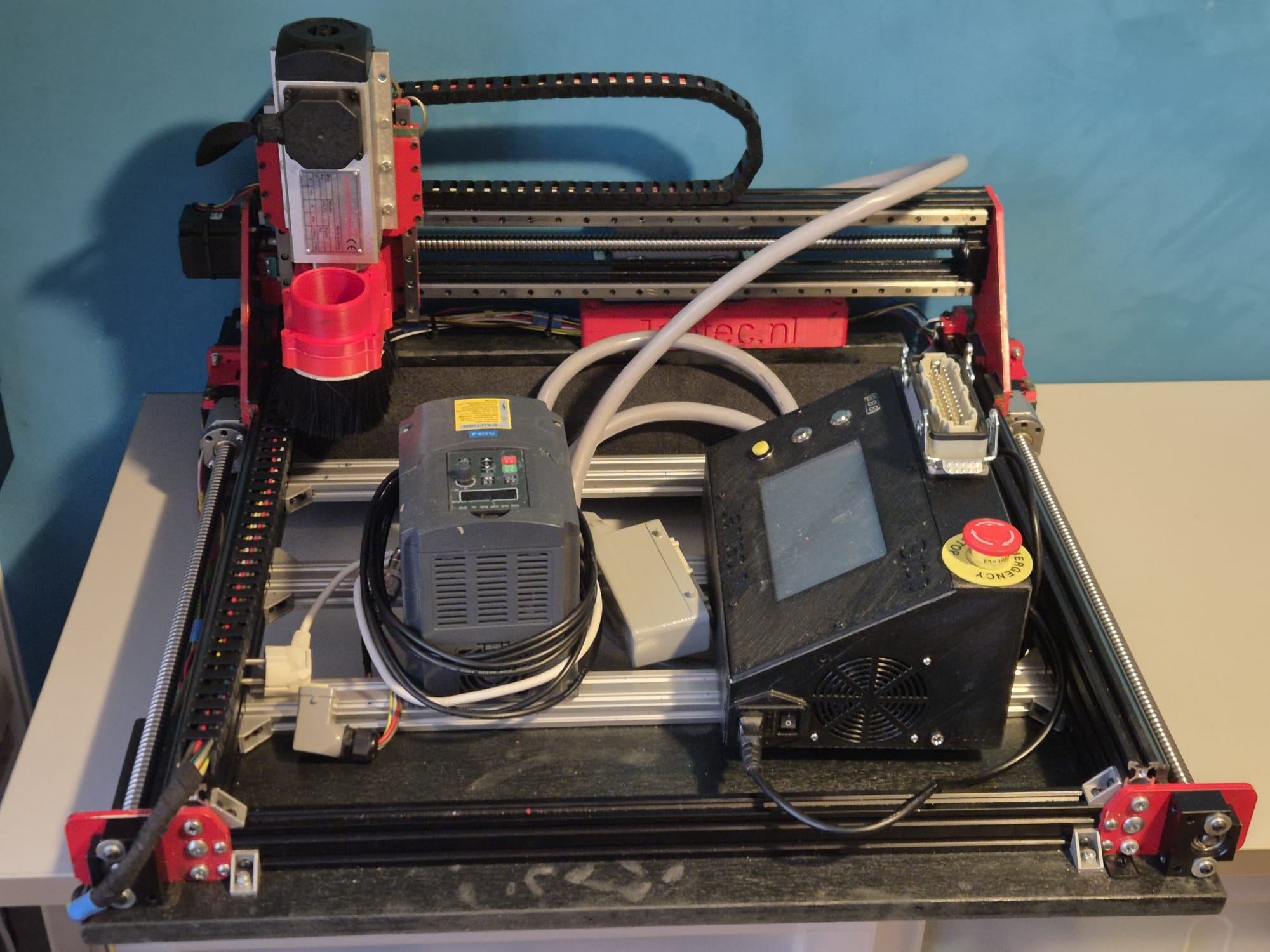
Kerstster deur/raamhanger Arduino nano en WS2812 LEDS en LDR

Geprint op de Voron2.4-300 met wit PETG filament.

De ster bestaat uit 5 gelijke delen. Je moet de 5 delen printen, de LED’s er doorheen voeren en daarna de draden er ergens uit laten komen.  De punten kun je na het monteren en testen aan elkaar lijmen met hotglue of superglue.

De 3 draden van de WS2812 LED string soldeer je aan de Arduino Nano (5V aan 5V, Gnd aan Gnd en de Data IN van de LED string soldeer je aan D3 of D5 van de Arduino Nano.  That’s it!   Daarna kun je de Arduino aan je PC koppelen met een data USB kabel en kun je de code downloaden van mijn website.

undefined

IK houd het meestal gemakkelijk en gebruik een telefoonlader met een USB kabel, die past in de Arduino nano.  Dan soldeer je de 3 draden van je WS2812 leds aan VIN (+), GND (-) en D5 (data).  Optioneel kun je een LDR (lichtgevoelige weerstand) aansluiten op A0 en Gnd.

In mijn latere ontwerpen heb ik dus een LDR toegevoegd tussen A0 en Gnd.  Met een stukje extra code is de intensiteit van de ster nu automatisch afgestemd op het omgevingslicht.  Daarnaast heb ik een aantal extra lichteffecten gemaakt.


Als je de Arduino IDE nog niet hebt, download dan de app van de Microsoft website (Arduino IDE).

Zorg dat je mijn Arduino code download en open dit met de Arduino IDE APP> Waarschijnlijk moet de APP de arduino INO file nog herplaatsen in een nieuwe directory maar dat hoort vanzelf te gaan. Zo niet, doe dat dan zelf even.

Selecteer in de Arduino IDE de juiste microprocessor (Arduino Nano)..  Vervolgens de juiste versie processor (groot of klein geheugen) en de oude of nieuwe bootloader.  Deze keuzes zijn afhankelijk van het soort Nano dat je hebt gekocht of nog had liggen.  Daarna kies je de juiste poort (USB) voor je Nano.

Om te testen of je verbinding hebt tussen IDE en Nano , kun je opvragen of de Arduino IDE je Nano kan lezen.  Pas hierna kun je de Nano gaan laden met het gecomplieerde programma.

Succes!

De Arduino code zonder LDR staat HIER.

De arduino code MET LDR staat HIER:

De STL file voor de 76cm ster staat HIER.  Deze moet je 5x printen en in elkaar lijmen.  De LEDS kun je binnen door elk segment voeren.  Dat is een beetje puzzelen maar echt mogelijk.  Zie het voorbeeld:

Ronde klok WS2812 & Arduino nano

ABOVE: Circular clock, completed project, reading 05h:41m and crossing to 05h:42m.  Red=hours, Green=minutes

Above: Clock without case, with open components.

READ THIS ARTICLE IN ENGLISH

In de bovenstaande video zie je alle benodigde onderdelen voor de electronica.  Een arduino Nano, een tijdmodule LS3231 met batterij back-up en een 4-delige ring met elk 15 stuks WS2812 LED’s die zorgen voor een 160mm 60 LED units klok.  Je kunt hem bouwen als een open gebouwde unit zoals hierboven afgebeeld met draad of in een 3d printbare slanke behuizing die ik heb ontwikkeld.  Zie de foto’s hieronder.

Voor het bouwen van deze mooie nauwkeurige klok, kun je mijn ontwerp files voor de behuizing gebruiken op elke 3d printer met een horizontale bed maat van minimaal 165x165mm.

Download de beide print STL’s OF van de Prusa gedeelde site waar ik deze ontwerpen heb geupload (zoek op de prusa site naar ws2812 circulaire arduino klok).

OF haal het STL bestand voor de VOORKANT van de klok van mijn website HIER

EN haal het STL bestand voor de ACHTERKANT van de klok van mijn website HIER

Eén STL is voor de achterkant en bevat de Nano box, de andere is voor de voorkant van de klok.  Positioneer de achterste STL 180 graden (dus omhoog gaat omlaag) in uw slicer, zodat zowel de doos als de LED-behuizing op Z-0 niveau zijn, d.w.z. naar beneden gericht op hetzelfde horizontale niveau.   De voorkant kan het best geprint worden met de platte kant naar beneden.  ABS is niet aan te raden omdat het minder stijf is, maar zal waarschijnlijk ook werken.  Voor mij werkt PETG of PLA het beste.

Gebruik wit filament voor het voorste deel, de achterkant kan elke kleur zijn die je wilt.

In de cirkel worden de 4 WS2812 LED segmenten in 1 volledige cirkel van ongeveer 160mm geplaatst.

Als je de elektronica aan de achterkant hebt aangesloten, schuift de voorkant er zo overheen. Geen lijm nodig.  Maar de LED ring kan best op 4 plaatsen met een druppel hotglue aan de basis van de achterste behuizing gelijmd worden.  Dit kun je het beste doen als je zeker weet dat alles goed werkt.

De LED onderdelen zijn verkrijgbaar op o.a. banggood , aliexpress en zo, zoek naar 60LED circle WS2812 die de 160 mm buitendiameter heeft.

Elke LED vertegenwoordigt een punt voor seconden, minuten of als uur indicator.

De kleuren bepalen de functie.  Blauw wordt ook gebruikt als kwartier indicator met minder intensiteit, om een gevoel van positionering te hebben voor de andere LEDS als het donker is.

Kijk naar de video hierboven van het ‘open’ demonstratiemodel om te begrijpen hoe het werkt.

Hieronder vindt je de Arduino code voor de gebruikte Nano3, as-is. het werkt voor mij, en in de code vindt u ook alle benodigde elektrische aansluitingen en de specificaties van de gebruikte Time module.

Haal de Arduino code HIER

Wanneer aangesloten op je PC, kun je de Arduino programmeren en via de seriële interface kun je naderhand speciale instellingen van de klok wijzigen, zoals helderheid, speciale kwartierverlichtingsindicatoren, enzovoort. het staat allemaal in de code hieronder.

De aansturing kan via een seriële interface met de usb ingang van de Arduino, via een terminalprogramma zoals YAT of met de interface van het Arduino IDE programma.

De commando’s zijn:

f; fader UIT
F; fader AAN
m (getal); dim de 4 blauwe marker LED’s met waarde (getal)
S; synchroniseren met RTC tijd
s; synchroniseren met systeemtijd (computer)
t (tijd); systeemtijd veranderen in:
b; helderheid van alle niet-marker LED’s

Doneer a.j.b. $1 aan mijn paypal account als je (delen van) mijn ontwikkelde materialen gebruikt, zodat ik kan doorgaan met het delen van leuke dingen voor jou om te downloaden

Ik hoop dat alles goed gaat lukken!

Succes,

Jan

De Arduino code, te gebruiken voor het programmeren van de Arduino Nano3 is beschikbaar onderaan dit bericht als platte tekst om te importeren in een leeg arduino bestand (met kopiëren en plakken).

Zorg ervoor dat je alleen de bibliotheken en tijdmodule gebruikt die in de code zijn aangegeven!  De gebruikte tijdmodule is van de betere generatie die de tijd zeer goed vasthoudt, ook in stand-by.

Gebruik voor het verbinden van de draden tussen de neopixel segmenten, de arduino en de tijdmodule een temperatuurgeregelde soldeerbout.  Gebruik een ventilator als je aan het solderen bent en adem geen giftige gassen in tijdens het solderen.

De Arduino code is hieronder weergegeven, te importeren in Arduino IDE in een .ino bestand.  Met de Arduino IDE moet je vervolgens de code compileren om de Arduino Nano geflasht te krijgen met het programma.


/**
* NeoClock
*
* Clock using 60 WS2812B/Neopixel LEDs and DS3231 RTC
* Small changes and updates made by jan Griffioen, Amsterdam Europe 2018-2021
* Libraries needed:
* * Adafruit NeoPixel (Library Manager) – Phil Burgess / Paint Your Dragon for Adafruit Industries – LGPL3
* *
* * Arduino Timezone Library (https://github.com/JChristensen/Timezone) – Jack Christensen – CC-BY-SA
* * Time Library (https://github.com/PaulStoffregen/Time) – Paul Stoffregen, Michael Margolis – LGPL2.1
*/

#include <Adafruit_NeoPixel.h>
#ifdef __AVR__
#include <avr/power.h>
#endif

#if defined(ESP8266)
#include <pgmspace.h>
#else
#include <avr/pgmspace.h>
#endif

/* for software wire use below
#include <SoftwareWire.h> // must be included here so that Arduino library object file references work
#include <RtcDS3231.h>

SoftwareWire myWire(SDA, SCL);
RtcDS3231<SoftwareWire> Rtc(myWire);
for software wire use above */

/* for normal hardware wire use below */
#include <Wire.h> // must be included here so that Arduino library object file references work
#include <RtcDS3231.h>
RtcDS3231<TwoWire> Rtc(Wire);
/* for normal hardware wire use above */

#include <TimeLib.h> //http://www.arduino.cc/playground/Code/Time
#include <Timezone.h> //https://github.com/JChristensen/Timezone

#include <EEPROM.h>

//Central European Time (Frankfurt, Paris)
TimeChangeRule CEST = {“CEST”, Last, Sun, Mar, 2, 120}; //Central European Summer Time
TimeChangeRule CET = {“CET “, Last, Sun, Oct, 3, 60}; //Central European Standard Time
Timezone CE(CEST, CET);

TimeChangeRule *tcr; //pointer to the time change rule, use to get the TZ abbrev
time_t utc;

#define PIN 5

unsigned long lastMillis = millis();
byte dimmer = 0x88;
byte hmark = 0;

byte ohour=0;
byte ominute=0;
byte osecond=0;

boolean fader=true;

Adafruit_NeoPixel strip = Adafruit_NeoPixel(60, PIN, NEO_GRB + NEO_KHZ800);

void setup() {

Serial.begin(57600);

strip.begin();
strip.setBrightness(50);

// Some example procedures showing how to display to the pixels:
// colorWipe(strip.Color(255, 0, 0), 50); // Red
//colorWipe(strip.Color(0, 255, 0), 50); // Green
//colorWipe(strip.Color(0, 0, 255), 50); // Blue
//colorWipe(strip.Color(0, 0, 0, 255), 50); // White RGBW
// Send a theater pixel chase in…
//theaterChase(strip.Color(127, 127, 127), 50); // White
theaterChase(strip.Color(127, 0, 0), 50); // Red
//theaterChase(strip.Color(0, 0, 127), 50); // Blue

//rainbow(20);
rainbowCycle(2);
//theaterChaseRainbow(50);

strip.clear();
strip.show(); // Initialize all pixels to ‘off’

Rtc.Begin();

Rtc.Enable32kHzPin(false);
Rtc.SetSquareWavePin(DS3231SquareWavePin_ModeNone);

if (!Rtc.GetIsRunning())
{
Serial.println(“Rtc was not actively running, starting now”);
Rtc.SetIsRunning(true);
}

if (!Rtc.IsDateTimeValid())
{
// Common Cuases:
// 1) the battery on the device is low or even missing and the power line was disconnected
Serial.println(“Rtc lost confidence in the DateTime!”);
}

byte eechk = EEPROM.read(0);
if(eechk == 0xAA) { //Assume this is our config and not a fresh chip
dimmer = EEPROM.read(1);
hmark = EEPROM.read(2);
fader = EEPROM.read(3);
}

timeSync();
}

void calcTime(void) {
utc = now();
CE.toLocal(utc, &tcr);
ohour = hour(utc);
ominute = minute(utc);
if(osecond != second(utc)) {
osecond = second(utc);
lastMillis = millis();

if(ominute == 0 && osecond == 0) {
//Every hour
timeSync();
}
}
}

void addPixelColor(byte pixel, byte color, byte brightness) {
color *= 8;
uint32_t acolor = brightness;
acolor <<= color;
uint32_t ocolor = strip.getPixelColor(pixel);
ocolor |= acolor;
strip.setPixelColor(pixel, ocolor);
}

void drawClock(byte h, byte m, byte s) {
strip.clear();

addPixelColor(m, 1, dimmer);

if(hmark > 0) {
for(byte i = 0; i<12; i++) {
addPixelColor((5*i), 2, hmark);
}
}

h %= 12;
h *= 5;
h += (m/12);
addPixelColor(h, 2, dimmer);
// 0x RR GG BB

if(fader) {
byte dim_s1 = dimmer;
byte dim_s2 = 0;
byte px_s2 = s+1;
if(px_s2 >= 60) px_s2 = 0;
unsigned long curMillis = millis()-lastMillis;
if(curMillis < 250) {
dim_s2 = 0;
dim_s1 = dimmer;
}else{
dim_s2 = map(curMillis, 250, 1000, 0, dimmer);
dim_s1 = dimmer – map(curMillis, 250, 1000, 0, dimmer);
}

// Add blue low intensity dots for 12(0),3, 6 and 9 O’çlock to verify where the clock is positioned..
addPixelColor(15, 128, 10);
addPixelColor(30, 128, 10);
addPixelColor(45, 128, 10);
addPixelColor(0, 128, 40);

addPixelColor(s, 0, dim_s1);
addPixelColor(px_s2, 0, dim_s2);
}else{
addPixelColor(s, 0, dimmer);
}

// add a background color
// setBrightness(Serial.parseInt());
// uint16_t j;
// for(j=0; j<60; j++) { // 1 cycles of colors on wheel
// strip.setPixelColor(j, Wheel(((j * 256 / strip.numPixels()) + j) & 255));
// }

strip.show();
}

byte rounds = 0;

void loop() {
calcTime();

if(rounds++ > 100) {
Serial.print(ohour);
Serial.print(“:”);
Serial.print(ominute);
Serial.print(“:”);
Serial.print(osecond);
Serial.println(“(C)JG-2020”);
rounds = 0;

}
//rainbow(21);
if (osecond == 59){theaterChase(strip.Color(0, 0, 127), 40); }// Blue; }
//if (ominute == 59 AND osecond == 59){theaterChase(strip.Color(0, 127, 0), 50); }// Green}
//if (ohour == 11 AND ominute == 59 AND osecond == 59){theaterChase(strip.Color(127, 127, 0), 50); }// Green}
else {drawClock(ohour,ominute,osecond);}

delay(10);

chkSer();
}

void timeSync(void) {
RtcDateTime dt = Rtc.GetDateTime();
setTime(dt.Hour(),dt.Minute(),dt.Second(),dt.Day(),dt.Month(),dt.Year());

Serial.print(“Synced to: “);
Serial.print(dt.Year());
Serial.print(“-“);
Serial.print(dt.Month());
Serial.print(“-“);
Serial.print(dt.Day());
Serial.print(“-“);
Serial.print(dt.Hour());
Serial.print(“-“);
Serial.print(dt.Minute());
Serial.print(“-“);
Serial.println(dt.Second());
}

void timeSave(void) {
utc = now();

RtcDateTime store = RtcDateTime(year(utc), month(utc), day(utc), hour(utc), minute(utc), second(utc));
Rtc.SetDateTime(store);

Serial.print(“Synced to: “);
Serial.print(year(utc));
Serial.print(“-“);
Serial.print(month(utc));
Serial.print(“-“);
Serial.print(day(utc));
Serial.print(“-“);
Serial.print(hour(utc));
Serial.print(“-“);
Serial.print(minute(utc));
Serial.print(“-“);
Serial.println(second(utc));

}

void setBrightness(byte brightness) {
dimmer = brightness;
}

void chkSer(void) {
unsigned int iy;
byte im,id,iH,iM,iS;

if(!Serial.available()) return;

switch(Serial.read()) {
case ‘b’:
setBrightness(Serial.parseInt());
Serial.print(F(“Brightness changed to: “));
Serial.println(dimmer);
EEPROM.put(0, 0xAA);
EEPROM.put(1, dimmer);
break;
case ‘t’:
iy = Serial.parseInt();
im = Serial.parseInt();
id = Serial.parseInt();
iH = Serial.parseInt();
iM = Serial.parseInt();
iS = Serial.parseInt();
setTime(iH,iM,iS,id,im,iy);
Serial.println(F(“System time changed”));
break;
case ‘f’:
fader = false;
EEPROM.put(0, 0xAA);
EEPROM.put(3, 0);
Serial.println(F(“Fader off”));
break;
case ‘F’:
fader = true;
EEPROM.put(0, 0xAA);
EEPROM.put(3, 1);
Serial.println(F(“Fader on”));
break;
case ‘m’:
hmark = Serial.parseInt();
EEPROM.put(0, 0xAA);
EEPROM.put(2, hmark);
Serial.println(F(“HMark changed”));
break;
case ‘s’:
timeSync();
Serial.println(F(“Synced RTC to System”));
break;
case ‘S’:
timeSave();
Serial.println(F(“Synced System to RTC”));
break;
default:
Serial.println(‘?’);
}
}

// Fill the dots one after the other with a color
void colorWipe(uint32_t c, uint8_t wait) {
for(uint16_t i=0; i<strip.numPixels(); i++) {
strip.setPixelColor(i, c);
strip.show();
delay(wait);
}
}

void rainbow(uint8_t wait) {
uint16_t i, j;

for(j=0; j<256; j++) {
for(i=0; i<strip.numPixels(); i++) {
strip.setPixelColor(i, Wheel((i+j) & 25));//255
}
strip.show();
delay(wait);
}
}

// Slightly different, this makes the rainbow equally distributed throughout
void rainbowCycle(uint8_t wait) {
uint16_t i, j;

for(j=0; j<256*5; j++) { // 5 cycles of all colors on wheel
for(i=0; i< strip.numPixels(); i++) {
strip.setPixelColor(i, Wheel(((i * 256 / strip.numPixels()) + j) & 255));
}
strip.show();
delay(wait);
}
}

//Theatre-style crawling lights.
void theaterChase(uint32_t c, uint8_t wait) {
for (int j=0; j<4; j++) { //do 4 cycles of chasing
for (int q=0; q < 3; q++) {
for (uint16_t i=0; i < strip.numPixels(); i=i+3) {
strip.setPixelColor(i+q, c); //turn every third pixel on
}
strip.show();

delay(wait);

for (uint16_t i=0; i < strip.numPixels(); i=i+3) {
strip.setPixelColor(i+q, 0); //turn every third pixel off
}
}
}
}

//Theatre-style crawling lights with rainbow effect
void theaterChaseRainbow(uint8_t wait) {
for (int j=0; j < 256; j++) { // cycle all 256 colors in the wheel
for (int q=0; q < 3; q++) {
for (uint16_t i=0; i < strip.numPixels(); i=i+3) {
strip.setPixelColor(i+q, Wheel( (i+j) % 255)); //turn every third pixel on
}
strip.show();

delay(wait);

for (uint16_t i=0; i < strip.numPixels(); i=i+3) {
strip.setPixelColor(i+q, 0); //turn every third pixel off
}
}
}
}

// Input a value 0 to 255 to get a color value.
// The colours are a transition r – g – b – back to r.
uint32_t Wheel(byte WheelPos) {
WheelPos = 255 – WheelPos;
if(WheelPos < 85) {
return strip.Color(255 – WheelPos * 3, 0, WheelPos * 3);
}
if(WheelPos < 170) {
WheelPos -= 85;
return strip.Color(0, WheelPos * 3, 255 – WheelPos * 3);
}
WheelPos -= 170;
return strip.Color(WheelPos * 3, 255 – WheelPos * 3, 0);
}

STL files voor Minimill WMD16LV CNC conversie direct drive adapters downloads met NEMA23 stappenmotoren

Doneer alsjeblieft $1 naar mijn paypal account als je (delen van) mijn ontwikkelde materialen gebruikt, zodat ik leuke dingen kan blijven delen die je kunt downloaden en -gebruiken

KLIK op de URL om het downloaden van het bijbehorende STL-bestand te starten

MINIMILL_BF16L CNC_Y_adapter direct 2022_07_25_V1_5-jantec.nl


MINIMILL_BF16L CNC_X_adapter direct drive 2022_07_25_V1_5-jantec.nl


STL download voor de TOP direct drive adapter van de WMD16LV minifrees en Nema23 stappenmotor

MINIMILL_BF16L CNC_Z_adapter direct drive 2022_07_25_V1_5-jantec.nl


Kolomfrees CNC conversie WMD16LV Z-as 3d geprint adapterblok voor NEMA23 direct drive

Terwijl ik mijn CNC adapterplaten met tandwielen en riemen aan het maken was, ontdekte ik dat er niet veel kant-en-klaar bestaat voor deze conversies.

Daarom ben ik ook adapteronderdelen voor direct drive aan het maken, om dit uit te proberen.  Ik heb er sterkere NEMA23 motoren voor aangeschaft.

DOWNLOAD:

MINIMILL_BF16L CNC_Z_adapter direct drive 2022_07_25_V1_5-jantec.nl


Dit is het derde deel dat ik maak, voor de Z-as.

Dit onderdeel is vrij eenvoudig: Eerst moet de adapter goed passen op de bovenkant van de Z-kolom, en de gaten voor de 4 bouten moeten precies goed zijn.  Hetzelfde geldt voor het gat van de geleidingsschroef van de lagerhouder.

Daarbovenop wordt de Nema23 houder/montage geprojecteerd.  Inclusief alle benodigde boutgaten, moergaten en een zijgat voor het aandraaien van de koppeling.

De lead schroef heeft een buitendeel voor het handwiel dat we gaan gebruiken voor CNC dat 10mm is, en wat schroefdraad 10mm voor Z. De schroefdraad is nodig om de hoeklagers (niet bedoeld voor zijdelingse torsie) met wat torsie aan de lagerhouder te kunnen vastschroeven.

Als je directe aandrijving doet, heb je een speciaal koppelstuk nodig dat in 2 kan worden gesplitst. Dan monteer je eerst één deel op de loodspil met wat ringen tussen de molen en het koppelstuk zodat de moer in het koppelstuk kan worden geplaatst.  Als de schroefdraad te lang is, slijp je er wat af.

Plaats vervolgens het rubber (met middengat) terug in het gemonteerde deel van de koppeling en duw het andere deel in het rubber, zodat de koppeling compleet is.

Monteer vervolgens de geprinte adapter met reeds gemonteerde Nema23 motor op de Y-as en duw de Nema as in de koppeling.  Gebruik het rechter werkvenster van de adapter om het koppelstuk op de Nema-as aan te draaien en klaar is kees!

Mocht je ook een handwiel willen hebben dan kan dat, maar dan moet je een stepper kopen met een as die zowel aan de voor- als aan de achterzijde zit (dit heet ‘dubbele as’ maar is eigenlijk een langere as, uiteraard).

GA NAAR de X-as Direct Drive adapter

GA NAAR de Y-as Direct Drive adapter

DOWNLOAD DE LAATSTE STL VERSIE VAN DIT ONDERDEEL

Please donate $1 to my paypal account if you use (parts of) my developed materials so I can continue to share nice stuff for you to download

Kolomfrees CNC conversie WMD16LV X-as adapterblok 3d geprint voor NEMA23 direct drive

Terwijl ik mijn CNC adapterplaten met tandwielen en riemen aan het maken was, ontdekte ik dat er niet veel kant-en-klaar bestaat voor deze conversies.

Daarom ben ik ook adapteronderdelen voor directe aandrijving aan het maken, om dit uit te proberen.

DOWNLOAD:

MINIMILL_BF16L CNC_X_adapter direct drive 2022_07_25_V1_5-jantec.nl


Dit is het tweede adapter onderdeel dat ik heb gemaakt, voor de X-as.

De lead schroef heeft een buitendeel voor het handwiel dat we gaan gebruiken voor CNC dat 10mm is, en wat schroefdraad 8mm.  De schroefdraad is nodig om de hoeklagers (niet bedoeld voor zijdelingse torsie) met wat torsie aan de lagerhouder te bouten.

Als je direct drive doet, heb je een speciaal koppelstuk nodig dat in 2 kan worden gesplitst. Dan monteer je eerst één deel op de loodspil met wat ringen tussen de molen en het koppelstuk zodat de moer in het koppelstuk kan worden geplaatst.  Als de schroefdraad te lang is, slijp je er wat af.

Plaats vervolgens het rubber (met middengat) terug in het gemonteerde deel van de koppeling en duw het andere deel in het rubber, zodat de koppeling compleet is.

Monteer vervolgens de geprinte adapter met reeds gemonteerde Nema23 motor op de Y-as en duw de Nema as in de koppeling.  Gebruik het rechter werkvenster van de adapter om het koppelstuk op de Nema-as aan te draaien en klaar is kees!

Er kan ook een handwiel op maar dan moet je een stepper kopen met een as die zowel aan de voor- als aan de achterzijde zit (dit heet ‘dubbele as’ maar is eigenlijk gewoon een langere as.

GA NAAR de Direct Drive Y-as adapter

GA naar de Direct Drive Z-as adapter

DOWNLOAD DE LAATSTE VERSIE 

Please donate $1 to my paypal account if you use (parts of) my developed materials so I can continue to share nice stuff for you to download

Kolomfrees CNC conversie WMD16LV Y-as adapterblok 3d geprint voor NEMA23 direct drive

Terwijl ik mijn CNC adapterplaten met tandwielen en riemen aan het maken was, ontdekte ik dat er niet veel kant-en-klaar bestaat voor deze conversies.

Daarom ben ik ook adapteronderdelen voor directe aandrijving aan het maken, om dit uit te proberen.

Dit is de eerste, te beginnen met de moeilijkste.  De rest zal spoedig worden toegevoegd.

DOWNLOAD:

MINIMILL_BF16L CNC_Y_adapter direct 2022_07_25_V1_5-jantec.nl

Versie 1.2 die 15 mm korter is en veel robuuster:

De lead schroef heeft een buitendeel voor het handwiel dat we gaan gebruiken voor CNC dat 10mm is, en wat schroefdraad 8mm.  De schroefdraad is nodig om de hoeklagers (niet bedoeld voor zijdelingse torsie) met wat torsie aan de lagerhouder te bouten.

Als je directe aandrijving doet, heb je een speciaal koppelstuk nodig dat in 2 kan worden gesplitst. Dan monteer je eerst een deel op de loodspil met wat ringen tussen de molen en het koppelstuk zodat de moer in het koppelstuk kan worden geplaatst.  Als de schroefdraad te lang is, slijp je er wat af.

Plaats vervolgens het rubber (met middengat) terug in het gemonteerde deel van de koppeling en duw het andere deel in het rubber, zodat de koppeling compleet is.

Monteer vervolgens de geprinte adapter met reeds gemonteerde Nema23 motor op de Y-as en duw de Nema as in de koppeling.  Gebruik het rechter werkvenster van de adapter om het koppelstuk op de Nema-as aan te draaien en klaar is kees!

Mocht je ook een handwiel willen hebben, dan zul je een stepper moeten kopen met een as die zowel voor als achter zit. (dit heet ‘dubbele as’ maar is eigenlijk een langere as, uiteraard.

OF- mijn laatste ontwerp werkt een beetje anders: zet eerst een paar 10mm ringen op de 10mm as van de leadcrew, en schroef dan een RVS buis met schroefdraad met een buitendiameter van 12mm, 25 mm lang en inwendige 8mm schroefdraad op de as.  Dit gaat in een 12 naar 8mm coupler en deze coupler wordt aangesloten op een NEMA23 stappenmotor met een 8 mm as.  Het wordt wel een beetje langdradig maar het werkt heel goed.  Gewoon de RVS schroefdraadbuis aan het 8mm draadeind van de leadcrew vastschroeven en het loopt prima!

Dit is de laatste versie, gebaseerd op de bovenstaande opstelling:

GA NAAR de Direct Drive X-adapter

GA NAAR de Direct Drive Z-adapter

DOWNLOAD DE LAATSTE VERSIE STL FILE

Please donate $1 to my paypal account if you use (parts of) my developed materials so I can continue to share nice stuff for you to download

CNC-ombouw van mijn Toolmania WBM16LV (TM BF 16) kolomfrees

GO TO THE ENGLISH VERSION

Al voordat ik mijn Toolmania WBM16LV kolomfrees had aangeschaft, had ik plannen voor de ombouw naar volledige CNC bediening.

Omdat ik al wat ervaring heb met 3d printers en al 2 CNC routers in bedrijf heb, is de ombouw van de kolomfrees naar CNC technisch niet ingewikkeld.

Wat het wel lastig maakt is de te maken keuze: Ga ik gelijk de spindels vervangen met ball bearing spindels of niet?  Voorlopig nog maar even niet, eerst alles maar eens op CNC maken en dan zie ik daarna wel hoe verder.

De kolomfrees is wel alvast voorzien van glaslinealen met digitale uitlezing.  Verder wordt er nog een gasveer gemonteerd op de Z-kolom zodat niet steeds al het gewicht als het ware in de weg zit bij heen en weer bewegen.  Ook een automatisch smeersysteem voor de glij-sledes van X- Y en Z-as wordt nog gemonteerd.

Ga naar de X-as CNC adapter

Ga naar de Y-as CNC adapter

Finale montage

Ga naar de Z-as CNC adapter

Finale montage

Voor de electronica heb ik OpenCNC spullen besteld, en vooralsnog ga ik werken met de Mach3 hard-en software die ik nog heb liggen.

GOTO the X axis CNC adapter

GOTO the Y axis CNC adapter

GOTO the Z axis CNC adapter


CNC conversie WMD16LV kolomfrees Z-as 3d geprinte adapter voor NEMA23 en M3 tandriem en tandwielen

Nieuwe versie V3 na de tweede paspoging:

De bevestiging op de Z-kolom moest OMHOOG zodat het NEMA23 tandwiel op dezelfde hoogte komt als het wiel dat op de draadspil is gemonteerd.

Benodigde hardware:

3d geprinte Z-as adapter
Nema23 stepper 76 mm lengte met voldoende koppel, 8mm as diameter
48 tanden M3 tandwiel van 11mm breed, 10mm gat met kraag voor de draadspil
24 tanden M3 tandwiel van 11mm breedte, 8mm gat met kraag voor de Nema23 stappenmotor
nieuwe M6 bouten 40mm lengte flathead voor de top verbinding met de Z kolom
4 bouten en moeren M5 voor montage van de Nema 23 stappenmotor
tandriem 300mm M3 (100 tanden) 9 of 10mm

OF, gebruik het 72 tandwiel op de aandrijfschroef en verkrijg een grotere lengte riem van (ik schat) 330-350 mm

OF… een andere manier om de Nema23stepper te monteren is aan de achterkant van de Z-kolom, MAAR ik wil niet dat hij aan de achterkant uitsteekt, daarom heb ik besloten de stepper links van de Z-kolom te monteren…

Dit is het 72 tanden 11 mm brede tandwiel dat ik waarschijnlijk zal gebruiken voor de uiteindelijke bevestiging op de Z-assen. Maar niet met deze beugel aan de achterkant. Helaas past deze beugel niet gemakkelijk aan de linker- of rechterkant van de Z-kolom. Misschien maak ik wel een passtuk om hem aan de linkerkant te monteren. We zullen zien hoe goed de 3D geprinte onderdelen zullen presteren en als het nodig is zal de Z-as het gemakkelijkst te gebruiken zijn met een standaard beugel om de stappenmotor te monteren zoals hierboven getoond.

GA NAAR de X as tandriem adapter

GA NAAR de Y as tandriem adapter

DOWNLOAD THE CNC ADAPTER DESIGNS 

Please donate $1 to my paypal account if you use (parts of) my developed materials so I can continue to share nice stuff for you to download

STL download  voor de riem-aangedreven adapters van de WMD16LV mini-tafelfrees en Nema23 

Please donate $1 to my paypal account if you use (parts of) my developed materials so I can continue to share nice stuff for you to download

CLICK op de download URL om de betreffende STL file te laden

DOWNLOADS Y-adapter (LEFT SIDE):

MINIMILL_BF16L CNC_Y_adapter belt driven 2023_04_23_V1 Jantec.nl MINIMILL_BF16L CNC_Y_adapter LID belt driven 2023_04_23_V1 Jantec.nl


DOWNLOADS X-adapter (FRONT SIDE):

MINIMILL_BF16L CNC_X_adapter belt driven 2023_04_23_V1 Jantec.nl MINIMILL_BF16L CNC_X_adapter LID belt driven 2023_04_23_V1 Jantec.nl


DOWNLOAD Z-adapter (TOP):

MINIMILL_BF16L CNC_Z_adapter belt driven 2023_04_23_V1 Jantec.nl


GOANAAR DE MINIFREES PAGINA

CNC conversie WMD16LV kolomfrees X-as 3d geprinte adapter voor NEMA23 en M3 tandriem en tandwielen

Nieuwe versie met beschermkap:

Je kunt de hele bodem en de beschermkap met de bevestigingskolommen voor de stappenmotor in één keer 3dprinten, zoals ik heb gedaan in rood ABS bij 270 graden C

Voor deze opstelling heb je nodig

1 stuks Nema23 stappenmotor met 56 lengte en 6.35 mm as
1 wiel met 12 tandjes M3 met kraag, gat-ø 6.35 mm, 11 mm breed
1 wiel met 24 tandjes M3 met GEEN kraag, gat-ø 10 mm, 11 mm breed
Getande M3 riem, 9 mm breed en lengte 255 of 275 mm (moet dit controleren)
3D geprinte onderdelen
M8 ringen en moer

Hier wordt de verbinding getoond op de X-as / loodspil lagerhouder met 2 M6 schroeven

Deksel:

En het freesontwerp voor de bodemplaat voor CNC-bewerking in aluminium mocht je dit liever hebben.

Het 3D-printbestand voor het deksel en de profielen voor de stappenmotor, te plaatsen op de aluminium gefreesde grondplaat:

GA NAAR de Y as tandriem adapter

GA NAAR de Z as tandriem adapter

DOWNLOAD THE CNC ADAPTER DESIGNS  as STL

Please donate $1 to my paypal account if you use (parts of) my developed materials so I can continue to share nice stuff for you to download


CNC conversie WMD16LV kolomfrees Y-as 3d geprinte adapter voor NEMA23 en M3 tandriem en tandwielen

Het ontwerp voor de Y-as montageplaat voor de Nema23 stepper is hieronder te zien en kan 3dprinted worden of, zoals ik ga doen nadat het geprinte deel goed blijkt te passen, CNC in aluminium op mijn CNC Indymill router.

De Y-as adapter bleek het moeilijkste ontwerp te zijn.  Het kostte me 15 proefprints voordat ik alles volledig geoptimaliseerd had.  En ik wilde ook een debree scherm hebben met een verwijderbaar deksel, wat wat energie kostte om dit te testen.  Ook moet de riem een schone route hebben waar hij tussen het wiel zit.

De fysieke gegevens voor deze opstelling:

  • Nema23 stappenmotor
  • 3D geprinte onderdelen:
    • a: Baseplate inclusief stijgprofielen voor de motorbevestiging en afscherming;
    • b: deksel
  • Tandwiel voor de Nema23 8mm as: 10mm breed, 24 tanden M3 met borst
  • Tandwiel voor de loodspil 10mm as: 10mm breed: 48 tanden M3 met borst, gefreesd op de getande binnenkant 9mm diepte met een breedte van 33 mm diameter om te passen in de borst van de loodspil lagerhouder
  • De tandriem is 9mm breed, 300 mm lang en heeft 100 tanden (M3)

Uiteindelijke ONTWERP:

Het binnenste deel op de draaibank gefreesd zodat het ongeveer 9 mm over de lagerhouder van de Y-as kan schuiven

En nu kan het wiel over de lagerhouder naar rechts

Dit bespaart 9 mm inbouwruimte en nu kan het bewerkte handwiel worden vervangen, indien gewenst.  Maar het handwiel moet eerst worden bewerkt, om de aanduidingsring eraf te krijgen.

de kleine gaatjes kunnen worden gebruikt om het deksel op het spatscherm te plaatsen met kleine schroeven van 2,5 mm dia Of, je kunt het deksel eraf laten en er een wiel op zetten zoals ik heb gedaan op de Z-as.  Je moet de draaiknop van het wiel affrezen zodat hij dun genoeg wordt om op het overgebleven M8 draadeind te monteren.  Een klein stukje van de 10mm as zal bij mijn methode uitsteken om het handwiel gecentreerd te houden.

GA NAAR de X as tandriem adapter

GA NAAR de Z as tandriem adapter

DOWNLOAD THE CNC ADAPTER DESIGNS   as STL!

Please donate $1 to my paypal account if you use (parts of) my developed materials so I can continue to share nice stuff for you to download


Windbelt door Shawn Frayne

Met de windbelt van Shawn Frayne kun je op elk plekje waar de wind waait energie opwekken.

Ook al is het maar weinig, je kan er je telefoon (langzaam) mee opladen..

Shawn Frayne patenteerde zijn uitvinding en maakte het gratis voor persoonlijk gebruik!

Na een paar jaar ging Shawn over op andere ontwikkelingen.

Het gebruik en de toepassingen van riemaangedreven generatoren voor elektrische energie zijn zeldzaam en worden zelden gebruikt.

De uitdaging ligt in de levensduur van de riem, die moet oscilleren om stroom op te wekken.

Voor eenvoudige toepassingen wordt meestal een oude VHS-band als riem gebruikt.

Als je een grotere lengte riem wilt gebruiken, kun je een dikkere riem gebruiken, maar dan moet hij wel gemakkelijk kunnen oscilleren in de wind.

Lees mijn artikel over hoe dit werkt:

DHZ Windbelt

Wind Power Revolution _ Eco Wanderer

Micro Humdinger by Shawn Frayne, first prototype

Citroën ID/DS downloads NL

Achteruitrijlamp

afhangen plaatwerk id-ds

ALG-4-12 ALG-13-17 ALG-18-26 ALG-27-30 ALG-32-35 ALG-42-51 ALG-52-58

Banden Michelin ID-DS

banden-omtrek

Citroen

Conservering-instructies

Conservering-kofferbak

Conservering-restauratie

Dakrand reparatie ID-DS

Doorsmeren 5000km

DS handboek DI volgnummer 01 Pagina DI 0 Voorblad

DS handboek DI volgnummer 02 Handelingen 000-001 Pagina DI 1-8

DS handboek DI volgnummer 03 Handelingen 002-100 Pagina DI 9-26

DS handboek DI volgnummer 04 Handelingen 100-142 Pagina DI 26-61

DS handboek DI volgnummer 05 Handelingen 142-144 Pagina DI 63-74

DS handboek DI volgnummer 06 Handelingen 144-144 Pagina DI 75-76

DS handboek DI volgnummer 07 Handelingen 144-144 Pagina DI 77-95

DS handboek DI volgnummer 08 Handelingen 144-144 Pagina DI 96-98

DS handboek DI volgnummer 09 Handelingen 144-144 Pagina DI 99-100

DS handboek DI volgnummer 10 Handelingen 144-144 Pagina DI 101-117

DS handboek DI volgnummer 11 Handelingen 144-144 Pagina DI 102

DS handboek DI volgnummer 12 Handelingen 144-144 Pagina DI 119-124

DS handboek DI volgnummer 13 Handelingen 144-144 Pagina DI 125-126

DS handboek DI volgnummer 14 Handelingen 173-210 Pagina DI 127-138

DS handboek DI volgnummer 15 Handelingen 210-210 Pagina DI 139-140

DS handboek DI volgnummer 16 Handelingen 210-220 Pagina DI 143-154

DS handboek DI volgnummer 17 Handelingen 230-314 Pagina DI 155-171

DS handboek DI volgnummer 18 Handelingen 142-144 Pagina DI 173-178

DS handboek DI volgnummer 19 Handelingen 142-144 Pagina DI 179-204

DS handboek DI volgnummer 20 Handelingen 142-144 Pagina DI 205-224

DS handboek DI volgnummer 21 Handelingen 390-430 Pagina DI 225-242

DS handboek DI volgnummer 22 Handelingen 142-144 Pagina DI 243-278

DS handboek DI volgnummer 23 Handelingen 142-144 Pagina DI 279-280-eind

DS handboek DII volgnummer 24 Handelingen 142-144 Pagina DII Voorblad

DS handboek DII volgnummer 25 Handelingen 142-144 Pagina DII 3-33

DS handboek DII volgnummer 26 Handelingen 100-100 Pagina DII 35-50

DS handboek DII volgnummer 27 Handelingen 100-100 Pagina DII 51-58

DS handboek DII volgnummer 28 Handelingen 142-144 Pagina DII 59-62

DS handboek DII volgnummer 29 Handelingen 142-144 Pagina DII 62-66

DS handboek DII volgnummer 30 Handelingen 112-112 Pagina DII 67-84

DS handboek DII volgnummer 31 Handelingen 112-122 Pagina DII 85-92

DS handboek DII volgnummer 32 Handelingen 142-144 Pagina DII 93-115

DS handboek DII volgnummer 33 Handelingen 142-144 Pagina DII 115-141

DS handboek DII volgnummer 34 Handelingen 142-144 Pagina DII 142-143

DS handboek DII volgnummer 35 Handelingen 142-144 Pagina DII 145-147

DS handboek DII volgnummer 36 Handelingen 330-334 Pagina DII 149-160

DS handboek DII volgnummer 37 Handelingen 334-334 Pagina DII 161-176

DS handboek DII volgnummer 38 Handelingen 334-350 Pagina DII 177-188

DS handboek DII volgnummer 39 Handelingen 142-144 Pagina DII 214-238

Dubbel:  BII 0097_001 BII 0098_001 BII 142-143 BII 239-260 BII 261-276 BII 277-292 BII 293-306 BII 307-316 BII 317-326 BII 326-eind

Dubbel: DI 1-8 DI 9-26 DI 26-61 DI 63-76 vouwpagina eerste deel DI 75-76 DI 77-95 DI 96-98 DI 99-100 DI 101-102 DI 101-117 DI 119-124 DI 125 fout vouwpagina mist 2 delen A4 DI 125-126 DI 127-138 DI 139-140 DI 173-178 DI 179-204 DI 243-278 DI 279-280-eind DI Voorblad DII 3-33 DII 59-62 DII 62-65 DII 93-115 DII 115-141 DII 145-147 DII 214-238 DII Voorblad

Elektra-schema uitleg

GereedschapMededelingen

Goot-schelp reparatie ID-DS

Hogedrukregelaar-werking

hydrauliek werking deel 1

hydrauliek werking deel 2

Hydrauliekolie vervangen

Hydrauliek-uitleg

instructieboekje-DS-3e-neus-NL

Koplamp demping revisie

koplamp facelift

koplampen afstellen

lekzak achter ID-DS

lekzak voor ID-DS

LPG in DS

Luchtfilter reinigen

plaatwerk afhangen

Remaccu-voorraadbol-werking

revisiehoogtregelaards

S1-2 S1-8 S3-7 S7-15 S9-15 S16-20 S16-22 S22-32 S33 S34-36 SB-135D-140D SB-141D-148D SB-149D-153D SB-154D-159D SB-161D-164D SB-165D-166D SB-167D-175D SB-176D-185D SB-186D-194D SB-195D-200D SB-201D-202D SB-203D-206D SB-208D-212D

Schokbreker-werking

ServiceBulletins

stuurhuis afstellen lek rondsel

stuurhuis afstellen

stuurhuis controleren op speling

Stuurhuis lek

stuurhuishoes vervangen

stuurwiel vervangen

technischeMededelingD55

technischeMededelingen

Temperatuurmeter inbouw

TM-1-4 TM-4(4D) TM-6-17 TM-19-28 TM-29-32 TM-37-43 TM-44-45 TM-46-52 TM-53-58 TM-59-68 TM-69-78

Ventilator-regelbaar

vetnippels op draagarmen


Engelstalige manuals:

Camshaft characteristics and valve settings Citroën DS21 DX2 types, 1974

Repair manual Citroën for all D types volume 1, December 1974

Repair manual Citroën for all D types volume 2, December 1974

PART 3 manual ID/DS English // Electrical System

PART 4 manual ID/DS English // Bodywork

Wiring Diagram, Cabling, Bulbs and wiring colors Citroën DX DJ DY DT DV from September 1969 onwards

Wiring Diagram only – Citroën DX DJ DY DT DV from September 1969 onwards

Ronde klok WS2812 & Arduino nano

READ THIS ARTICLE IN ENGLISH

In de bovenstaande video zie je alle benodigde onderdelen voor de electronica.  Een arduino Nano, een tijdmodule LS3231 met batterij back-up en een 4-delige ring met elk 15 stuks WS2812 LED’s die zorgen voor een 160mm 60 LED units klok.  Je kunt hem bouwen als een open gebouwde unit zoals hierboven afgebeeld met draad of in een 3d printbare slanke behuizing die ik heb ontwikkeld.  Zie de foto’s hieronder.

Voor het bouwen van deze mooie nauwkeurige klok, kun je mijn ontwerp files voor de behuizing gebruiken op elke 3d printer die een horizontale bed size heeft van minimaal 165x165mm.

Pak de beide print STL’s . HIER. van de Prusa gedeelde site waar ik deze ontwerpen heb geupload. (Als de link breekt, zoek op de prusa site naar ws2812 circulaire arduino klok).

OF haal het STL bestand voor de VOORKANT van de klok van mijn website HIER

EN haal het STL bestand voor de achterkant van de klok van mijn website HIER

Eén STL is voor de achterkant en bevat de Nano box, de andere is voor de voorkant van de klok.  Positioneer de achterste STL 180 graden (dus omhoog gaat omlaag) in uw slicer, zodat zowel de doos als de LED-behuizing op Z-0 niveau zijn, d.w.z. naar beneden gericht op hetzelfde horizontale niveau.   De voorkant kan het best geprint worden met de platte kant naar beneden.  ABS is niet aan te raden omdat het minder stijf is, maar zal waarschijnlijk ook werken.  Voor mij werkt PETG of PLA het beste.

Gebruik wit filament voor het voorste deel, de achterkant kan elke kleur zijn die je wilt.

In de cirkel worden de 4 WS2812 LED segmenten in 1 volledige cirkel van ongeveer 160mm geplaatst.

Als je de elektronica aan de achterkant hebt aangesloten, schuift de voorkant er zo overheen. Geen lijm nodig.  Maar de LED ring kan best op 4 plaatsen met een druppel hotglue aan de basis van de achterste behuizing gelijmd worden.  Dit kun je het beste doen als je zeker weet dat alles goed werkt.

De LED onderdelen zijn verkrijgbaar op o.a. banggood , aliexpress en zo, zoek naar 60LED circle WS2812 die de 160 mm buitendiameter heeft.

Elke LED vertegenwoordigt een punt voor seconden, minuten of als uur indicator.

De kleuren detemine de functie.  Blauw wordt ook gebruikt als kwartier indicator met minder intensiteit, om een gevoel van positionering te hebben voor de andere LEDS als het donker is.

Kijk naar de video hierboven van het ‘open’ demonstratiemodel om te begrijpen hoe het werkt.

Hieronder vindt u de Arduino code voor de gebruikte Nano3, as-is. het werkt voor mij, en in de code vindt u ook alle benodigde elektrische aansluitingen en de specificaties van de gebruikte Time module.

Wanneer aangesloten op je PC, kun je de Arduino programmeren en via de seriële interface kun je naderhand speciale instellingen van de klok wijzigen, zoals helderheid, speciale kwartierverlichtingsindicatoren, enzovoort. het staat allemaal in de code hieronder.

De aansturing kan via een seriële interface met de usb ingang van de Arduino, via een terminalprogramma zoals YAT of met de interface van het Arduino IDE programma.

De commando’s zijn:

f; fader UIT
F; fader AAN
m (getal); dim de 4 blauwe marker LED’s met waarde (getal)
S; synchroniseren met RTC tijd
s; synchroniseren met systeemtijd (computer)
t (tijd); systeemtijd veranderen in:
b; helderheid van alle niet-marker LED’s

Doneer a.j.b. $1 aan mijn paypal account als je (delen van) mijn ontwikkelde materialen gebruikt, zodat ik kan doorgaan met het delen van leuke dingen voor jou om te downloaden

Ik hoop dat alles goed gaat lukken!

Succes,

Jan

De Arduino code, te gebruiken voor het programmeren van de Arduino Nano3 is beschikbaar onderaan dit bericht als platte tekst om te importeren in een leeg arduino bestand (met kopiëren en plakken).

Zorg ervoor dat je alleen de bibliotheken en tijdmodule gebruikt die in de code zijn aangegeven!  De gebruikte tijdmodule is van de betere generatie die de tijd zeer goed vasthoudt, ook in stand-by.

Gebruik voor het verbinden van de draden tussen de neopixel segmenten, de arduino en de tijdmodule een temperatuurgeregelde soldeerbout.  Gebruik een ventilator als je aan het solderen bent en adem geen giftige gassen in tijdens het solderen.

De Arduino code is hieronder weergegeven, te importeren in Arduino IDE in een .ino bestand.  Met de Arduino IDE moet je vervolgens de code compileren om de Arduino Nano geflasht te krijgen met het programma.


/**
* NeoClock
*
* Clock using 60 WS2812B/Neopixel LEDs and DS3231 RTC
* Small changes and updates made by jan Griffioen, Amsterdam Europe 2018-2021
* Libraries needed:
* * Adafruit NeoPixel (Library Manager) – Phil Burgess / Paint Your Dragon for Adafruit Industries – LGPL3
* *
* * Arduino Timezone Library (https://github.com/JChristensen/Timezone) – Jack Christensen – CC-BY-SA
* * Time Library (https://github.com/PaulStoffregen/Time) – Paul Stoffregen, Michael Margolis – LGPL2.1
*/

#include <Adafruit_NeoPixel.h>
#ifdef __AVR__
#include <avr/power.h>
#endif

#if defined(ESP8266)
#include <pgmspace.h>
#else
#include <avr/pgmspace.h>
#endif

/* for software wire use below
#include <SoftwareWire.h> // must be included here so that Arduino library object file references work
#include <RtcDS3231.h>

SoftwareWire myWire(SDA, SCL);
RtcDS3231<SoftwareWire> Rtc(myWire);
for software wire use above */

/* for normal hardware wire use below */
#include <Wire.h> // must be included here so that Arduino library object file references work
#include <RtcDS3231.h>
RtcDS3231<TwoWire> Rtc(Wire);
/* for normal hardware wire use above */

#include <TimeLib.h> //http://www.arduino.cc/playground/Code/Time
#include <Timezone.h> //https://github.com/JChristensen/Timezone

#include <EEPROM.h>

//Central European Time (Frankfurt, Paris)
TimeChangeRule CEST = {“CEST”, Last, Sun, Mar, 2, 120}; //Central European Summer Time
TimeChangeRule CET = {“CET “, Last, Sun, Oct, 3, 60}; //Central European Standard Time
Timezone CE(CEST, CET);

TimeChangeRule *tcr; //pointer to the time change rule, use to get the TZ abbrev
time_t utc;

#define PIN 5

unsigned long lastMillis = millis();
byte dimmer = 0x88;
byte hmark = 0;

byte ohour=0;
byte ominute=0;
byte osecond=0;

boolean fader=true;

Adafruit_NeoPixel strip = Adafruit_NeoPixel(60, PIN, NEO_GRB + NEO_KHZ800);

void setup() {

Serial.begin(57600);

strip.begin();
strip.setBrightness(50);

// Some example procedures showing how to display to the pixels:
// colorWipe(strip.Color(255, 0, 0), 50); // Red
//colorWipe(strip.Color(0, 255, 0), 50); // Green
//colorWipe(strip.Color(0, 0, 255), 50); // Blue
//colorWipe(strip.Color(0, 0, 0, 255), 50); // White RGBW
// Send a theater pixel chase in…
//theaterChase(strip.Color(127, 127, 127), 50); // White
theaterChase(strip.Color(127, 0, 0), 50); // Red
//theaterChase(strip.Color(0, 0, 127), 50); // Blue

//rainbow(20);
rainbowCycle(2);
//theaterChaseRainbow(50);

strip.clear();
strip.show(); // Initialize all pixels to ‘off’

Rtc.Begin();

Rtc.Enable32kHzPin(false);
Rtc.SetSquareWavePin(DS3231SquareWavePin_ModeNone);

if (!Rtc.GetIsRunning())
{
Serial.println(“Rtc was not actively running, starting now”);
Rtc.SetIsRunning(true);
}

if (!Rtc.IsDateTimeValid())
{
// Common Cuases:
// 1) the battery on the device is low or even missing and the power line was disconnected
Serial.println(“Rtc lost confidence in the DateTime!”);
}

byte eechk = EEPROM.read(0);
if(eechk == 0xAA) { //Assume this is our config and not a fresh chip
dimmer = EEPROM.read(1);
hmark = EEPROM.read(2);
fader = EEPROM.read(3);
}

timeSync();
}

void calcTime(void) {
utc = now();
CE.toLocal(utc, &tcr);
ohour = hour(utc);
ominute = minute(utc);
if(osecond != second(utc)) {
osecond = second(utc);
lastMillis = millis();

if(ominute == 0 && osecond == 0) {
//Every hour
timeSync();
}
}
}

void addPixelColor(byte pixel, byte color, byte brightness) {
color *= 8;
uint32_t acolor = brightness;
acolor <<= color;
uint32_t ocolor = strip.getPixelColor(pixel);
ocolor |= acolor;
strip.setPixelColor(pixel, ocolor);
}

void drawClock(byte h, byte m, byte s) {
strip.clear();

addPixelColor(m, 1, dimmer);

if(hmark > 0) {
for(byte i = 0; i<12; i++) {
addPixelColor((5*i), 2, hmark);
}
}

h %= 12;
h *= 5;
h += (m/12);
addPixelColor(h, 2, dimmer);
// 0x RR GG BB

if(fader) {
byte dim_s1 = dimmer;
byte dim_s2 = 0;
byte px_s2 = s+1;
if(px_s2 >= 60) px_s2 = 0;
unsigned long curMillis = millis()-lastMillis;
if(curMillis < 250) {
dim_s2 = 0;
dim_s1 = dimmer;
}else{
dim_s2 = map(curMillis, 250, 1000, 0, dimmer);
dim_s1 = dimmer – map(curMillis, 250, 1000, 0, dimmer);
}

// Add blue low intensity dots for 12(0),3, 6 and 9 O’çlock to verify where the clock is positioned..
addPixelColor(15, 128, 10);
addPixelColor(30, 128, 10);
addPixelColor(45, 128, 10);
addPixelColor(0, 128, 40);

addPixelColor(s, 0, dim_s1);
addPixelColor(px_s2, 0, dim_s2);
}else{
addPixelColor(s, 0, dimmer);
}

// add a background color
// setBrightness(Serial.parseInt());
// uint16_t j;
// for(j=0; j<60; j++) { // 1 cycles of colors on wheel
// strip.setPixelColor(j, Wheel(((j * 256 / strip.numPixels()) + j) & 255));
// }

strip.show();
}

byte rounds = 0;

void loop() {
calcTime();

if(rounds++ > 100) {
Serial.print(ohour);
Serial.print(“:”);
Serial.print(ominute);
Serial.print(“:”);
Serial.print(osecond);
Serial.println(“(C)JG-2020”);
rounds = 0;

}
//rainbow(21);
if (osecond == 59){theaterChase(strip.Color(0, 0, 127), 40); }// Blue; }
//if (ominute == 59 AND osecond == 59){theaterChase(strip.Color(0, 127, 0), 50); }// Green}
//if (ohour == 11 AND ominute == 59 AND osecond == 59){theaterChase(strip.Color(127, 127, 0), 50); }// Green}
else {drawClock(ohour,ominute,osecond);}

delay(10);

chkSer();
}

void timeSync(void) {
RtcDateTime dt = Rtc.GetDateTime();
setTime(dt.Hour(),dt.Minute(),dt.Second(),dt.Day(),dt.Month(),dt.Year());

Serial.print(“Synced to: “);
Serial.print(dt.Year());
Serial.print(“-“);
Serial.print(dt.Month());
Serial.print(“-“);
Serial.print(dt.Day());
Serial.print(“-“);
Serial.print(dt.Hour());
Serial.print(“-“);
Serial.print(dt.Minute());
Serial.print(“-“);
Serial.println(dt.Second());
}

void timeSave(void) {
utc = now();

RtcDateTime store = RtcDateTime(year(utc), month(utc), day(utc), hour(utc), minute(utc), second(utc));
Rtc.SetDateTime(store);

Serial.print(“Synced to: “);
Serial.print(year(utc));
Serial.print(“-“);
Serial.print(month(utc));
Serial.print(“-“);
Serial.print(day(utc));
Serial.print(“-“);
Serial.print(hour(utc));
Serial.print(“-“);
Serial.print(minute(utc));
Serial.print(“-“);
Serial.println(second(utc));

}

void setBrightness(byte brightness) {
dimmer = brightness;
}

void chkSer(void) {
unsigned int iy;
byte im,id,iH,iM,iS;

if(!Serial.available()) return;

switch(Serial.read()) {
case ‘b’:
setBrightness(Serial.parseInt());
Serial.print(F(“Brightness changed to: “));
Serial.println(dimmer);
EEPROM.put(0, 0xAA);
EEPROM.put(1, dimmer);
break;
case ‘t’:
iy = Serial.parseInt();
im = Serial.parseInt();
id = Serial.parseInt();
iH = Serial.parseInt();
iM = Serial.parseInt();
iS = Serial.parseInt();
setTime(iH,iM,iS,id,im,iy);
Serial.println(F(“System time changed”));
break;
case ‘f’:
fader = false;
EEPROM.put(0, 0xAA);
EEPROM.put(3, 0);
Serial.println(F(“Fader off”));
break;
case ‘F’:
fader = true;
EEPROM.put(0, 0xAA);
EEPROM.put(3, 1);
Serial.println(F(“Fader on”));
break;
case ‘m’:
hmark = Serial.parseInt();
EEPROM.put(0, 0xAA);
EEPROM.put(2, hmark);
Serial.println(F(“HMark changed”));
break;
case ‘s’:
timeSync();
Serial.println(F(“Synced RTC to System”));
break;
case ‘S’:
timeSave();
Serial.println(F(“Synced System to RTC”));
break;
default:
Serial.println(‘?’);
}
}

// Fill the dots one after the other with a color
void colorWipe(uint32_t c, uint8_t wait) {
for(uint16_t i=0; i<strip.numPixels(); i++) {
strip.setPixelColor(i, c);
strip.show();
delay(wait);
}
}

void rainbow(uint8_t wait) {
uint16_t i, j;

for(j=0; j<256; j++) {
for(i=0; i<strip.numPixels(); i++) {
strip.setPixelColor(i, Wheel((i+j) & 25));//255
}
strip.show();
delay(wait);
}
}

// Slightly different, this makes the rainbow equally distributed throughout
void rainbowCycle(uint8_t wait) {
uint16_t i, j;

for(j=0; j<256*5; j++) { // 5 cycles of all colors on wheel
for(i=0; i< strip.numPixels(); i++) {
strip.setPixelColor(i, Wheel(((i * 256 / strip.numPixels()) + j) & 255));
}
strip.show();
delay(wait);
}
}

//Theatre-style crawling lights.
void theaterChase(uint32_t c, uint8_t wait) {
for (int j=0; j<4; j++) { //do 4 cycles of chasing
for (int q=0; q < 3; q++) {
for (uint16_t i=0; i < strip.numPixels(); i=i+3) {
strip.setPixelColor(i+q, c); //turn every third pixel on
}
strip.show();

delay(wait);

for (uint16_t i=0; i < strip.numPixels(); i=i+3) {
strip.setPixelColor(i+q, 0); //turn every third pixel off
}
}
}
}

//Theatre-style crawling lights with rainbow effect
void theaterChaseRainbow(uint8_t wait) {
for (int j=0; j < 256; j++) { // cycle all 256 colors in the wheel
for (int q=0; q < 3; q++) {
for (uint16_t i=0; i < strip.numPixels(); i=i+3) {
strip.setPixelColor(i+q, Wheel( (i+j) % 255)); //turn every third pixel on
}
strip.show();

delay(wait);

for (uint16_t i=0; i < strip.numPixels(); i=i+3) {
strip.setPixelColor(i+q, 0); //turn every third pixel off
}
}
}
}

// Input a value 0 to 255 to get a color value.
// The colours are a transition r – g – b – back to r.
uint32_t Wheel(byte WheelPos) {
WheelPos = 255 – WheelPos;
if(WheelPos < 85) {
return strip.Color(255 – WheelPos * 3, 0, WheelPos * 3);
}
if(WheelPos < 170) {
WheelPos -= 85;
return strip.Color(0, WheelPos * 3, 255 – WheelPos * 3);
}
WheelPos -= 170;
return strip.Color(WheelPos * 3, 255 – WheelPos * 3, 0);
}

FLY CDY V2 SDcard content download

Since the FLY_CDY_V2 STM32 board comes without any firmware installed, I made a simple link for you to download and extract everything you need to a 2-16GB microSDcard. 

Just download, extract, burn as-is to SD and plug it in the board, fire the board up and all works!

Make sure you follow the guideline HERE for getting attached to the board via wifi by using a USB cable and YAT terminal on your PC to get the home wifi SSID and Password programmed to ROM into the board, AFTER you installed firmware by putting in the SDcard and firing it up.

The settings in config.g at the SDcard are made for a Cartesian XYZ machine with triple extruder.  This can all be changed to fit your build in config.g. 

For a delta, use THIS DUET2wifi DELTA config.g and change the pin_name of bed heater  according to the FLY_CDY_V2 name convention (thus: use bed instead of bed_heater).  

For more info about the board and connecting to the electronics, steppers, endstops, filament sensors, BLTouch, Neopixels etcetera go HERE

Please donate $1 to my paypal account if you use (parts of) my developed materials so I can continue to share nice stuff for you to download


Cheers,


Jan Griffioen

Arduino led bar demo & programma voor 64×16 Canton electronics LED matrix

Module No.:  TB275

//#include <AT24Cxx.h>//no lib needed since we will only use basic functions in 1 page at first

// Author: Phil Kaziewicz 19th July 2014,
// Jan Griffioen did quite some ADDITIONS july-nov 2014 such as RTC, temp, humidity, barmetric pressure, stringtext in time, funny roll-ups etc and voidstructuring
// 64×16 LED display matrix test code
// based upon original code from canton-electonics
// Arduino 1.0.6 NANO V4.0 (with the 2008 Windows drivers; these work with W8.1;

// add buttons or wire bridges for intensity (if possible), speed, language, time up and time down (both last buttons work more agressively when kept pushing…)
// will also try to adapt rotary switches for settings…
// D9& D?? are free for this
// A1 and A3, A6 and higher are free for this, preferrably with a resistor network like on the LCD shields, that should only consume 1 A-pin…
// Add a device for proximity and connect to a ‘button’ input for something like speed or intensity// crash,…
// The development is done with a Nano, after all is OK the pro mini will be glued to the rear of the board and one time programmed via a USB to TTL converter.
// Re-programming only on request!

#include <dht.h>

// Example testing sketch for various DHT humidity/temperature sensors
// Written by ladyada, public domain

#define DHTPIN 16 // what pin we’re connected to; A2=D16

// Uncomment whatever type you’re using!
#define DHTTYPE DHT11 // DHT 11
//#define DHTTYPE DHT22 // DHT 22 (AM2302)
//#define DHTTYPE DHT21 // DHT 21 (AM2301)

// Connect pin 1 (on the left) of the sensor to +5V
// NOTE: If using a board with 3.3V logic like an Arduino Due connect pin 1
// to 3.3V instead of 5V! with shield 5V is OK
// Connect pin 2 of the sensor to whatever your DHTPIN is
// Connect pin 4 (on the right) of the sensor to GROUND
// Connect a 10K resistor from pin 2 (data) to pin 1 (power) of the sensor

// Initialize DHT sensor for normal 16mhz Arduino
DHT dht(DHTPIN, DHTTYPE, 10);
// NOTE: For working with a faster chip, like an Arduino Due or Teensy, you
// might need to increase the threshold for cycle counts considered a 1 or 0.
// You can do this by passing a 3rd parameter for this threshold. It’s a bit
// of fiddling to find the right value, but in general the faster the CPU the
// higher the value. The default for a 16mhz AVR is a value of 6. For an
// Arduino Due that runs at 84mhz a value of 30 works.
// Example to initialize DHT sensor for Arduino Due:
//DHT dht(DHTPIN, DHTTYPE, 30);

//inputs for the select switches are: A1= Select, D9= Up and D7= Down

#define SelectPIN 15 //(=A1 when used digital) // what pin we’re connected to input for the select switch: A1= Select
#define UpPIN 9 // what pin we’re connected to input for the select switch: D9= Up
#define DownPIN 7 // what pin we’re connected to input for the select switch: D7= Down

#include <avr/pgmspace.h>
#include <Wire.h>
byte high = 0x00, low=0x00;//used for the AT24C32 chip addressing, no lib needed here
#include “RTClib.h”

RTC_DS1307 rtc; // this time module 1307 is connected to SCL (A5 on Nano) and SDA (A4 on Nano)
//#define AT24C32 0x50 //no lib needed here , address is correct though

boolean (Select)=false;
boolean (Up)=false;
boolean (Down)=false;
boolean (DEBUG)=true;

#define BMP085_ADDRESS 0x77 // I2C address of barometer BMP085 for barometer/temp/hight; this is also connected to SCL (A5 on Nano) and SDA (A4 on Nano)

const unsigned char OSS = 0; // Oversampling Setting

// Calibration values
int ac1;
int ac2;
int ac3;
unsigned int ac4;
unsigned int ac5;
unsigned int ac6;
int b1;
int b2;
int mb;
int mc;
int md;

//int wait; //, integer between 7 and 18, memory chip position low 1 and 2
int typeofclock; //, small clock or big clock 0 or 1 position low 3
int fun; //, with fun or just readouts 0 or 1 position low 3
int minormax; //, minimum screen or all of it 0 or 1 position low 4
int matrixwidth = 64;
int matrixheight = 16;

// b5 is calculated in bmp085GetTemperature(…), this variable is also used in bmp085GetPressure(…)
// so …Temperature(…) must be called before …Pressure(…).
long b5;

// Connections to board
const byte latchPin = 8;
const byte clockPin = 12;
const byte data_R1 = 10;
const byte data_R2 = 11;
const byte en_74138 = 2;
const byte la_74138 = 3;
const byte lb_74138 = 4;
const byte lc_74138 = 5;
const byte ld_74138 = 6;
byte ScanRow = 0;
unsigned long counter;
const int pinRandom = A0; // better to get this than use the standard C randomizer.. A0 can be freed if needed for anything else….

//const int wait = 100; // In milliseconds
const int length = 8;
int x[length], y[length];
int ptr, nextPtr;
int wait = 12; // In milliseconds (15 is nice), must be between 8 and 18
//int inc = -1;
int resetcounter=1;
//int waittemp = 15;

// declare the strings:
//String Shour,Shour1,Sminute,SdayOfWeek,Sday,Smonth,Sdate,Syear,ENtijd,Sminutesingle,Stotal;

/* #######################################
# RTC_DS1307 Datatypes (KEYWORD1)
#######################################

DateTime KEYWORD1
RTC_DS1307 KEYWORD1
RTC_Millis KEYWORD1

#######################################
# Methods and Functions (KEYWORD2)
#######################################

year KEYWORD2
month KEYWORD2
day KEYWORD2
hour KEYWORD2
minute KEYWORD2
second KEYWORD2
dayOfWeek KEYWORD2
secondstime KEYWORD2
unixtime KEYWORD2
begin KEYWORD2
adjust KEYWORD2
isrunning KEYWORD2
now KEYWORD2

#######################################
# Constants (LITERAL1)
#######################################
*/

char* dayNameEN[] = {
“g “, “Monday”, “Tuesday”, “Wednesday”, “Thursday”, “Friday”, “Saturday”, “Sunday”};
char* hourNameEN[] = {“twelve”, “one”, “two”, “three”, “four”, “five”, “six”, “seven”, “eight”, “nine”, “ten”, “eleven”, “twelve”, “one”};
// “two”, “three”, “four”, “five”, “six”, “seven”, “eight”, “nine”, “ten”, “eleven”, “twelve”};
char* monthNameEN[] = {“G “, ” January”, “February”, “March”, “April”, “May”, “June”, “July”, “August”, “September”, “October”, “November”, “December”};

byte buffer[256] = { // Display buffer (which is scanned by the interrupt timer) of 8×32 bytes
0x00, 0x00, 0x00, 0x00, 0x00, 0x00, 0x00, 0x00, 0x00, 0x00, 0x00, 0x00, 0x00, 0x00, 0x00, 0x00,
};

#include <fontsBIGREDLED.h>

// xxxxxxxxxxxxxxxxxxxxxxxxxxxxxxxxxxxxxxxxxxxxxxxxxxxxxxxxxxxxxxxxxxxxxxxxxxxxxxxxxxxxxxxxxxxxxxxxxxxxxxxxxxxxxxxxxxxxxxx
// Routine to print a single character in one of 8 columns
// Inputs:
// x is one of (0,16,24,32,40,48,56), for shifting purposes 64 should als be available….
// y (0 to 16 or 24 depending upon font size),
// n is either (0 to 9) or an ascii value, ascii as ([“”])??
// font=0 for big font, 2 for small font,
// inverse is true for an inverted character
void drawChar(uint16_t x, uint16_t y, byte n, byte font, boolean inverse) {
byte charbytes[16], fontrows, xover8 = x >> 3;
int index;
if (0 != (x % 8)) return; // x not a multiple of 8
if ((n > 9) && (n < 32)) return; // invalid character
if (font == 2) fontrows = 16; else fontrows = 8;
if ((n >= 0) && (n <= 9)) index = (n + 16) * fontrows; else index = (n – 32) * fontrows; // go to the right code for this character

// addressing start at buffer and add y (rows) * (WIDTH is 64 so WIDTH/8) is 8 plus (x / 8) is 0 to 7
byte *pDst = buffer + (y << 3) + xover8;
for (byte i = 0; i < fontrows; i++) { // fill up the charbytes array with the right bits
if (font == 0) charbytes[i] = pgm_read_byte(&(font8x8_basic[index + i]));
// if (font==1) charbytes[i] = pgm_read_byte(&(font8x8_extended[index+i]));
if (font == 2) charbytes[i] = pgm_read_byte(&(font8x16_basic[index + i]));
// reverse bit order for fonts 0 and 1
if (font != 2) {
charbytes[i] = (charbytes[i] & 0xF0) >> 4 | (charbytes[i] & 0x0F) << 4;
charbytes[i] = (charbytes[i] & 0xCC) >> 2 | (charbytes[i] & 0x33) << 2;
charbytes[i] = (charbytes[i] & 0xAA) >> 1 | (charbytes[i] & 0x55) << 1;
};
if (inverse) charbytes[i] = ~charbytes[i];
};
const byte *pSrc = charbytes; // point at the first set of 8 pixels
for (byte i = 0; i < fontrows; i++) {
*pDst = *pSrc; // populate the destination byte
pDst += 8; // go to next row on buffer
pSrc++; // go to next set of 8 pixels in character
}
};
// xxxxxxxxxxxxxxxxxxxxxxxxxxxxxxxxxxxxxxxxxxxxxxxxxxxxxxxxxxxxxxxxxxxxxxxxxxxxxxxxxxxxxxxxxxxxxxxxxxxxxxxxxxxxxxxxxxxxxxx
void moveLeft(byte pixels, byte rowstart, byte rowstop) { // routine to move certain rows on the screen “pixels” pixels to the left
byte row, column;
short unsigned int address;
for (column = 0; column < 8; column++) {
for (row = rowstart; row < rowstop; row++) {
address = (row << 3) + column; /// right here!
if (column == 7)
buffer[address] = buffer[address] << pixels; // shuffle pixels left on last column and fill with a blank
else { // shuffle pixels left and add leftmost pixels from next column
byte incomingchar = buffer[address + 1];
buffer[address] = buffer[address] << pixels;
for (byte x = 0; x < pixels; x++) {
buffer[address] += ((incomingchar & (128 >> x)) >> (7 – x)) << (pixels – x – 1);
};
}
}
}
};
// xxxxxxxxxxxxxxxxxxxxxxxxxxxxxxxxxxxxxxxxxxxxxxxxxxxxxxxxxxxxxxxxxxxxxxxxxxxxxxxxxxxxxxxxxxxxxxxxxxxxxxxxxxxxxxxxxxxxxxx
// set a single pixel on or off
void setPixel(byte x, byte y, byte colour) {
bitWrite(buffer[(y << 3) + (x >> 3)], 7 – (x & 7), colour);
};
// xxxxxxxxxxxxxxxxxxxxxxxxxxxxxxxxxxxxxxxxxxxxxxxxxxxxxxxxxxxxxxxxxxxxxxxxxxxxxxxxxxxxxxxxxxxxxxxxxxxxxxxxxxxxxxxxxxxxxxx
void drawRect(byte x1, byte y1, byte x2, byte y2, byte colour) {
for (byte x = x1; x <= x2; x++) {
setPixel(x, y1, colour);
setPixel(x, y2, colour);
};
for (byte y = y1; y <= y2; y++) {
setPixel(x1, y, colour);
setPixel(x2, y, colour);
};
};

//start VOID =====================================================================================
void drawLine(byte x1, byte y1, byte x2, byte y2, byte colour) {

//Draws a line, between the points (x1, y1) and (x2, y2) in this graphics context’s coordinate system.
//Parameters:
// x1 – the first point’s x coordinate.
// y1 – the first point’s y coordinate.
// x2 – the second point’s x coordinate.
// y2 – the second point’s y coordinate.

for (byte x = x1; x <= x2; x++) {
setPixel(x, y1, colour);
setPixel(x, y2, colour);
};
for (byte y = y1; y <= y2; y++) {
setPixel(x1, y, colour);
setPixel(x2, y, colour);
};
};

// xxxxxxxxxxxxxxxxxxxxxxxxxxxxxxxxxxxxxxxxxxxxxxxxxxxxxxxxxxxxxxxxxxxxxxxxxxxxxxxxxxxxxxxxxxxxxxxxxxxxxxxxxxxxxxxxxxxxxxx
void shiftOut(byte row) { // fast routine to shove out 8 columns into two rows via board’s shift registers
for (byte column = 0; column < 8; column++) {
byte index = column + (row << 3);
for (byte i = 0; i < 8; i++) {
PORTB &= ~(3 << (data_R1 – 8)); // data_R2 is LOW; data_R1 is LOW;
PORTB &= ~(1 << (clockPin – 8)); // digitalWrite(clockPin,LOW);
PORTB |= !((buffer[index] >> (7 – i)) & 0x01) << (data_R1 – 8); // top set of rows
PORTB |= !((buffer[index + 128] >> (7 – i)) & 0x01) << (data_R2 – 8); // bottom set of rows
PORTB |= 1 << (clockPin – 8); // digitalWrite(clockPin,HIGH);
};
};
};

// Scan a pair of rows on to the display from “buffer” via the interrupt
ISR(TIMER2_COMPA_vect) {
cli();
digitalWrite(en_74138, HIGH); // Turn off display
shiftOut(ScanRow); // Shift out 8 columns
digitalWrite(latchPin, LOW);
digitalWrite(latchPin, HIGH);
PORTD = (ScanRow << 3) | (PORTD & 0X87); // Highlight row: pins 3 4 5 6 (la_74138 lb_74138 lc_74138 ld_74138)
digitalWrite(en_74138, LOW); // Turn on display
ScanRow++; // Do the next pair of rows next time this routine is called
if (ScanRow == 16) ScanRow = 0;
sei();
};

//start VOID =====================================================================================
void wacht(int wachttijd)
{
for (int a = 0; a < wachttijd; a++ )
{
int val = digitalRead(SelectPIN); // must be Select read the input pin

if (val==LOW) // if key Select is pressed
{
Select=true; // set a binary state high here , then
return; //return to loop;
}

delay(1);
}
}

//======================================================================================================================================================
//void(* resetFunc) (void) = 0;//declare reset function at address 0

//======================================================================================================================================================
void runscreen(String Stotal)
{
int stringlength= (Stotal.length()+1);//+1
char timestring[stringlength];
Stotal.toCharArray(timestring,(stringlength));
static int count = 0;

for (int count = 0; count <= sizeof(timestring) -2; count++)//was timestring-1 but then there is 1 blank space in front of each roll
{
drawChar(56, 0, timestring[count % (sizeof(timestring)-1 )], 2, false);//timestring-1
// drawChar(56, 8, timestring[count % (sizeof(timestring)-1 )], 0, false);//timestring-1
for (byte i = 0; i < 9; i++)// move the text 9 pixels (not 8 because it looks better) to the left
{
moveLeft(1, 2, 32);
wacht(wait);
}
}
}
//XXXXXXXXXXXXXXXXXXXXXXXXXXXXXXXXXXXXXXXXXXXXXXXXXXXXXXXXXXXXXXXXXXXXXXXXXXXXXXXXXXXXXXXXXXXXXXXXXXXXXXXXXXXXXXXXXXXXXXXXXXXXXXXXXXXXXXXXXXXXX
void writescreensmall(String above, String under, int height)
{
char letter;
int aa;
int a;
for (a = 0; a < 8; a++ )
{letter = above.charAt(a);
aa=8*a;
drawChar(aa, height, (letter), 0, false);
}
for (a = 0; a < 8; a++ )
{letter = under.charAt(a);
aa=8*a;
drawChar(aa, 8, (letter), 0, false);
}
}

//XXXXXXXXXXXXXXXXXXXXXXXXXXXXXXXXXXXXXXXXXXXXXXXXXXXXXXXXXXXXXXXXXXXXXXXXXXXXXXXXXXXXXXXXXXXXXXXXXXXXXXXXXXXXXXXXXXXXXXXXXXXXXXXXXXXXXXXXXXXXX
void writescreenbig(String above, int height)
{
char letter;
int aa;
int a;
for (a = 0; a < 8; a++ )
{letter = above.charAt(a);
aa=8*a;
drawChar(aa, height, (letter), 2, false);
}
}
//XXXXXXXXXXXXXXXXXXXXXXXXXXXXXXXXXXXXXXXXXXXXXXXXXXXXXXXXXXXXXXXXXXXXXXXXXXXXXXXXXXXXXXXXXXXXXXXXXXXXXXXXXXXXXXXXXXXXXXXXXXXXXXXXXXXXXXXXXXXXXXXX
void setup() {
if (Select)switches() ; // if key select is pressed it is detected in void wait and returned to loop; from there to void switches…
pinMode(SelectPIN, INPUT); // N.O. push button switch
pinMode(UpPIN, INPUT); // N.O. push button switch
pinMode(DownPIN, INPUT); // N.O. push button switch

digitalWrite(SelectPIN, HIGH); // pull-ups on
digitalWrite(UpPIN, HIGH);// pull-ups on
digitalWrite(DownPIN, HIGH); // pull-ups on

Serial.begin(9600);
// InitDHT();//Does what’s necessary to prepare for reading DHT
dht.begin();
//delay(1300); // needed for DHT11

#ifdef AVR
Wire.begin();
#else
Wire1.begin(); // Shield I2C pins connect to alt I2C bus on Arduino Due
#endif
rtc.begin();

if (! rtc.isrunning()) {
//Serial.println(“RTC is NOT running!”);
// following line sets the RTC to the date & time this sketch was compiled
rtc.adjust(DateTime(__DATE__, __TIME__));
}
// rtc.adjust(DateTime(__DATE__, __TIME__)); // Q&D way to set the time anyway but take it off the program afterwards!

for ( int ptr = 0; ptr < length; ptr++ ) {
x[ptr] = 16 ; //numberOfHorizontal8bitsDisplays * 8 / 2
y[ptr] = 16 ; //numberOfVertical8bitsDisplays * 8 / 2
}
nextPtr = 0;
// Serial.println(“Humidity and temperature\n\n”);

bmp085Calibration();

// Set up Timer2 as the scanning interrupt timer
cli(); // clear interrupts
TCCR2A = 0; TCCR2B = 0; TCNT2 = 0;
TCCR2B |= (1 << CS12) | (1 << CS10); // Set 1024 prescaler
// 160Hz scan rate = 10 frames/second (16 pairs of rows)
OCR2A = 97; // 97 = (16,000,000 / (1024*160)) – 1
TCCR2A |= (1 << WGM21); TIMSK2 |= (1 << OCIE2A);

pinMode(latchPin, OUTPUT); pinMode(clockPin, OUTPUT);
pinMode(data_R1, OUTPUT); pinMode(data_R2, OUTPUT);

pinMode(en_74138, OUTPUT);
pinMode(la_74138, OUTPUT); pinMode(lb_74138, OUTPUT);
pinMode(lc_74138, OUTPUT); pinMode(ld_74138, OUTPUT);

digitalWrite(en_74138, LOW);
digitalWrite(data_R1, HIGH); digitalWrite(data_R2, HIGH);
counter = millis();
sei(); //allow interrupts

//READ the memory of the AT24C32 (and write te settings he
low=0x00;
// Serial.println();
// Serial.print(“DATA SETUP VOID READ: “);
for (int i=0;i<=20;i++)
{
Wire.beginTransmission(0x50);
Wire.write(high);
Wire.write(low);
Wire.endTransmission();
Wire.requestFrom(0x50 ,1);
int data=Wire.read();//char or int, can both be done?
delay(5);

// Serial.print (data)-48;
// Serial.print(“,”);
// Serial.println(low);
// delay(10);
if (low==1) wait=int(data)-48+8;
if (low==2) typeofclock=int(data)-48;
if (low==3) fun=int(data)-48;
if (low==4) minormax=int(data)-48;

low++;
}

// the values of the settings will be written in AT24C32 register and will be read in Setup void, every time the device (re)starts
// the values are:
// wait, integer between 0 and 9==> 8 to 18 position low 1
// typeofclock, small clock or big clock 0 or 1 position low 2
// fun, with fun or just readouts 0 or 1 position low 3
// minormax, minimum screen or all of it 0 or 1 position low 4
// Serial.println();
// Serial.print(” Transferred to program: wait= “);
// Serial.print(wait);
// Serial.print(“, typeofclock= “);
// Serial.print(typeofclock);
// Serial.print(“, fun= “);
// Serial.print(fun);
// Serial.print(“, minormax= “);
// Serial.print(minormax);

// Serial.println();

}

// Note that there’s no need to do anything with the screen in the main loop.
// Whatever’s in “buffer” is constantly scanned out.

//======================================================================================================================================================
void loop() {
// bmp085Calibration();
//delay(2000);
if (Select)switches() ; // if key select is pressed it is detected in void wait and returned to loop; from there to void switches…

// Reading temperature or humidity takes about 250 milliseconds!
// Sensor readings may also be up to 2 seconds ‘old’ (its a very slow sensor)
//float h = dht.readHumidity();
// Read temperature as Celsius
// float t = dht.readTemperature();
// Read temperature as Fahrenheit
// float f = dht.readTemperature(true);

// Check if any reads failed and exit early (to try again).
// if (isnan(h) || isnan(t) || isnan(f)) {
// Serial.println(“Failed to read from DHT sensor!”);
// return;
// }

// Compute heat index
// Must send in temp in Fahrenheit!
// float hi = dht.computeHeatIndex(f, h);
// float temperature = bmp085GetTemperature(bmp085ReadUT()); //MUST be called first
// float pressure = bmp085GetPressure(bmp085ReadUP());
// float atm = pressure / 101325; // “standard atmosphere”
// float altitude = calcAltitude(pressure); //Uncompensated caculation – in Meters

// Serial.print(“Humidity: “);
// Serial.print(h);
// Serial.print(” %\t”);
// Serial.print(“Temperature: “);
// Serial.print(t);
// Serial.print(” *C “);
// Serial.print(f);
// Serial.print(” *F\t”);
// Serial.print(“Heat index: “);
// Serial.print(hi);
// Serial.println(” *F”);

// Serial.println();//line break
// Serial.print(“Temperature: “);
// Serial.print(temperature, 2); //display 2 decimal places
// Serial.println(“deg C”);

// Serial.print(“Pressure: “);
// Serial.print(pressure, 0); //whole number only.
// Serial.println(” Pa (100 Pa = 1 millibar)”);

// Serial.print(“Standard Atmosphere: “);
// Serial.println(atm, 4); //display 4 decimal places

// Serial.print(“Altitude: “);
// Serial.print(altitude, 2); //display 2 decimal places
// Serial.println(” M”);

// Serial.println();//line break
// clearscreen();

// if (resetcounter == 4)resetFunc(); //call reset
// resetcounter=resetcounter+1;

clearscreen();
rollingtimeEN();
if (Select)switches() ; // if key select is pressed it is detected in void wait and returned to loop; from there to void switches…
rollingdateEN();
if (Select)switches() ; // if key select is pressed it is detected in void wait and returned to loop; from there to void switches…
runscreen(” “); //shiftout the display with blanks
clearscreen();
JMWG();

clearscreen();

if (typeofclock==0) return;
if (Select)switches() ; // if key select is pressed it is detected in void wait and returned to loop; from there to void switches…
if (typeofclock==0) return;
// clearscreen();
// writescreensmall (” Plaats “, ” je “,0);
// wacht(wait*140);
// if (Select)switches() ; // if key select is pressed it is detected in void wait and returned to loop; from there to void switches…
// writescreenbig (” Eigen “, 0);
// wacht(wait*140);
// if (Select)switches() ; // if key select is pressed it is detected in void wait and returned to loop; from there to void switches…
// writescreensmall (” tekst “, ” hier! “,0);
// wacht(wait*140);
// if (Select)switches() ; // if key select is pressed it is detected in void wait and returned to loop; from there to void switches…
clearscreen();
rollinghumidEN();
if (Select)switches() ; // if key select is pressed it is detected in void wait and returned to loop; from there to void switches…
rollingTempENF();
if (Select)switches() ; // if key select is pressed it is detected in void wait and returned to loop; from there to void switches…
rollingTempENC();
if (Select)switches() ; // if key select is pressed it is detected in void wait and returned to loop; from there to void switches…
rollingPressureEN();
if (Select)switches() ; // if key select is pressed it is detected in void wait and returned to loop; from there to void switches…
rollingHeightEN();
if (Select)switches() ; // if key select is pressed it is detected in void wait and returned to loop; from there to void switches…

clearscreen();
bigclock();
if (Select)switches() ; // if key select is pressed it is detected in void wait and returned to loop; from there to void switches…
clearscreen();
JMWG();
if (Select)switches() ; // if key select is pressed it is detected in void wait and returned to loop; from there to void switches…
clearscreen();
rollingtimeEN();
runscreen(” “); //shiftout the display with blanks
if (Select)switches() ; // if key select is pressed it is detected in void wait and returned to loop; from there to void switches…
clearscreen();
snake();
if (Select)switches() ; // if key select is pressed it is detected in void wait and returned to loop; from there to void switches…
clearscreen();
rollupclock();
if (Select)switches() ; // if key select is pressed it is detected in void wait and returned to loop; from there to void switches…
clearscreen();
JMWG();
if (Select)switches() ; // if key select is pressed it is detected in void wait and returned to loop; from there to void switches…

// wait = wait + inc;
// if ( wait < 8 ) inc = 1; //random(15,2);
// if ( wait > 15 ) inc = -1; //-random(15,2);
// wait=random (18,8);

};

//xxxxxxxxxxxxxxxxxxxxxxxxxxxxxxxxxxxxxxxxxxxxxxxxxxxxxxxxxxxxxxxxxxxxxxxxxxxxxxxxxxxxxxxxxxxxxxxxxxxxxxxxxxxxxxxxxxxx
void clearscreen()

// setPixel(x,y,colour) where if colour=0 pixel=off, if colour=1 pixel=on
{
int yy = 0;
int xx = 0;
for (yy = 0; yy <= 16; yy++)
{
for (xx = 0; xx <= 64; xx++)
{
setPixel(xx, yy, (0));
}
}
}

//======================================================================================================================================================
void rollingtimeEN()
{
DateTime now = rtc.now(); // Get data from the DS1307
int counthour;

if ( (int (now.hour())) > 11) {counthour = (int(now.hour())-12);}
else int counthour = int(now.hour());

String Shour = (hourNameEN[counthour]);
String Shour1 = (hourNameEN[(counthour+1)]);
int Sminutesingle = (now.minute());

String ENtijd = “Time ERROR”;

if ((Sminutesingle)==0) ENtijd = “exactly “+ Shour+ ” o’clock”;
else if ((Sminutesingle)==1) ENtijd = “1 minute past “+ Shour;
else if ((Sminutesingle)==15) ENtijd = “a quarter past “+ Shour;
// else if ((Sminutesingle)==29) ENtijd = “1 to half “+ Shour1;
else if ((Sminutesingle)==30) ENtijd = “half past “+ Shour;
// else if ((Sminutesingle)==31) ENtijd = “1 past half “+ Shour1;
else if ((Sminutesingle)==45) ENtijd = “a quarter to “+ Shour1;
else if ((Sminutesingle)==59) ENtijd = “1 minute to “+ Shour1;// + ” o’clock”;
else if (Sminutesingle > 1 && Sminutesingle < 29){ ENtijd = String(Sminutesingle)+ ” minutes past “+ Shour;}
else if (Sminutesingle > 31 && Sminutesingle < 59){ ENtijd = String(60-Sminutesingle)+ ” minutes to ” + Shour1;}
else if ((Sminutesingle)==60) ENtijd = “precisely “+ Shour1+ ” o’clock”;
else ENtijd =”Time ERROR”;

//define the timestring to be rolled here:

String Stotal = ” It is ” + ENtijd;

runscreen(Stotal);
}

//======================================================================================================================================================
void rollingdateEN()
{
DateTime now = rtc.now(); // Get data from the DS1307
String Sday = (dayNameEN[int(now.dayOfWeek())]);
String Sdate = String(now.day());
String Smonth = (monthNameEN[int(now.month())]);
String Syear = String(now.year()).substring(0,4);
String Stotal = “, ” + Sday + ‘ ‘ + Smonth + ‘ ‘ + Sdate + “, ” + Syear; //define the datestring to be rolled here
runscreen(Stotal);
clearscreen;
}

//start VOID =====================================================================================
void snake()
{
int matrixwidth = 64;
int matrixheight = 16;

for (int a = 0; a < (1000); a++) {
// Shift pointer to the next segment
ptr = nextPtr;
nextPtr = next(ptr);

setPixel(x[ptr], y[ptr], 1); // Draw the head of the snake

wacht(wait * 1);

if ( ! occupied(nextPtr) ) {
setPixel(x[nextPtr], y[nextPtr], 0); // Remove the tail of the snake

}

for ( int attempt = 0; attempt < 20; attempt++ ) {

// Jump at random one step up, down, left, or right
switch ( random(4) ) {
case 0: x[nextPtr] = constrain(x[ptr] + 1, 0, matrixwidth – 1); y[nextPtr] = y[ptr]; break;
case 1: x[nextPtr] = constrain(x[ptr] – 1, 0, matrixwidth – 1); y[nextPtr] = y[ptr]; break;
case 2: y[nextPtr] = constrain(y[ptr] + 1, 0, matrixheight – 1); x[nextPtr] = x[ptr]; break;
case 3: y[nextPtr] = constrain(y[ptr] – 1, 0, matrixheight – 1); x[nextPtr] = x[ptr]; break;
}

if ( ! occupied(nextPtr) ) {
break; // The spot is empty, break out the for loop
}
}
}
}

boolean occupied(int ptrA) {
for ( int ptrB = 0 ; ptrB < length; ptrB++ ) {
if ( ptrA != ptrB ) {
if ( equal(ptrA, ptrB) ) {
return true;
}
}
}

return false;
}

int next(int ptr) {
return (ptr + 1) % length;
}

boolean equal(int ptrA, int ptrB) {
return x[ptrA] == x[ptrB] && y[ptrA] == y[ptrB];
// wait=waittemp;
clearscreen();
}

//start VOID =====================================================================================
void bigclock()
{
clearscreen;
DateTime now = rtc.now(); // Date and time functions using a DS1307 RTC connected via I2C and Wire lib
// String Syear = String(now.year()).substring(2,4);

for (int aa = 0; aa <= 50; aa++)
{
DateTime now = rtc.now();
// writescreenbig ((String ((now.hour()/10) %10))+(String (now.hour()%10))+’:’+String((now.minute()/10) %10) + String(now.minute()%10)+’:’+ (String((now.second()/10)%10))+ String(now.second()%10),int((aa-25)/8));
writescreenbig ((String ((now.hour()/10) %10))+(String (now.hour()%10))+’:’+String((now.minute()/10) %10) + String(now.minute()%10)+’:’+ (String((now.second()/10)%10))+ String(now.second()%10),0);
wacht (wait*7);
writescreenbig ((String ((now.hour()/10) %10))+(String (now.hour()%10))+’ ‘+String((now.minute()/10) %10) + String(now.minute()%10)+’ ‘+ (String((now.second()/10)%10))+ String(now.second()%10),0);
// writescreenbig (String(now.hour()).substring(0,2)+’ ‘+ String(now.minute()).substring(0,2)+’ ‘+ String(now.second()).substring(0,2),int((aa-25)/8));
wacht (wait*7);
}
//clearscreen;
for (int aa = 0; aa <= 15; aa++)
{
DateTime now = rtc.now();
writescreenbig ((String ((now.day()/10) %10))+(String (now.day()%10))+’/’+String((now.month()/10) %10) + String(now.month()%10)+’/’+ String(now.year()).substring(2,4),0);
wacht (wait*5);
drawChar(16, -1, ‘-‘ , 2, false);
drawChar(40, -1, ‘-‘ , 2, false);
wacht (wait*5);
drawChar(16, -1, (92) , 2, false);
drawChar(40, -1, (92) , 2, false);
wacht (wait*5);
drawChar(16, -1, (124) , 2, false);
drawChar(40, -1, (124) , 2, false);
wacht (wait*5);
}
clearscreen;
}
//start VOID =====================================================================================
void rollupclock()
{
clearscreen();
DateTime now = rtc.now(); // Date and time functions using a DS1307 RTC connected via I2C and Wire lib

for (int aa = 17; aa >= 0; aa–)
{
DateTime now = rtc.now();
clearscreen();
writescreenbig ((String ((now.hour()/10) %10))+(String (now.hour()%10))+’:’+String((now.minute()/10) %10) + String(now.minute()%10)+’:’+ (String((now.second()/10)%10))+ String(now.second()%10),aa);
wacht (wait*2);
}
wacht(wait*100);
//for (int aa = 0; aa <= 17; aa++) //down and away
for (int aa = 0; aa >= -17; aa–) //up and away
{
clearscreen();
writescreenbig ((String ((now.hour()/10) %10))+(String (now.hour()%10))+’:’+String((now.minute()/10) %10) + String(now.minute()%10)+’:’+ (String((now.second()/10)%10))+ String(now.second()%10),aa);
wacht (wait*2);
}
clearscreen;
wacht(wait*30);
}
//start VOID =====================================================================================

void JMWG(){

int matrixwidth = 64;
int matrixheight = 16;

for (int a = 0; a < 1; a++ ) {
drawChar(16, 0, ‘J’, 2, false);
drawChar(24, 0, ‘M’, 2, false);
drawChar(32, 0, ‘W’, 2, false);
drawChar(40, 0, ‘G’, 2, false);

for ( int x = 0; x < matrixwidth – 1; x++ ) {
drawLine(x, 0, matrixwidth – 1 – x, matrixheight – 1, 1);
wacht(wait);
drawLine(x, 0, matrixwidth – 1 – x, matrixheight – 1, 0);
}

for ( int y = 0; y < matrixheight – 1; y++ ) {
drawLine(matrixwidth – 1, y, 0, matrixheight – 1 – y, 1);
wacht(wait);
drawLine(matrixwidth – 1, y, 0, matrixheight – 1 – y, 0);
}
}
}
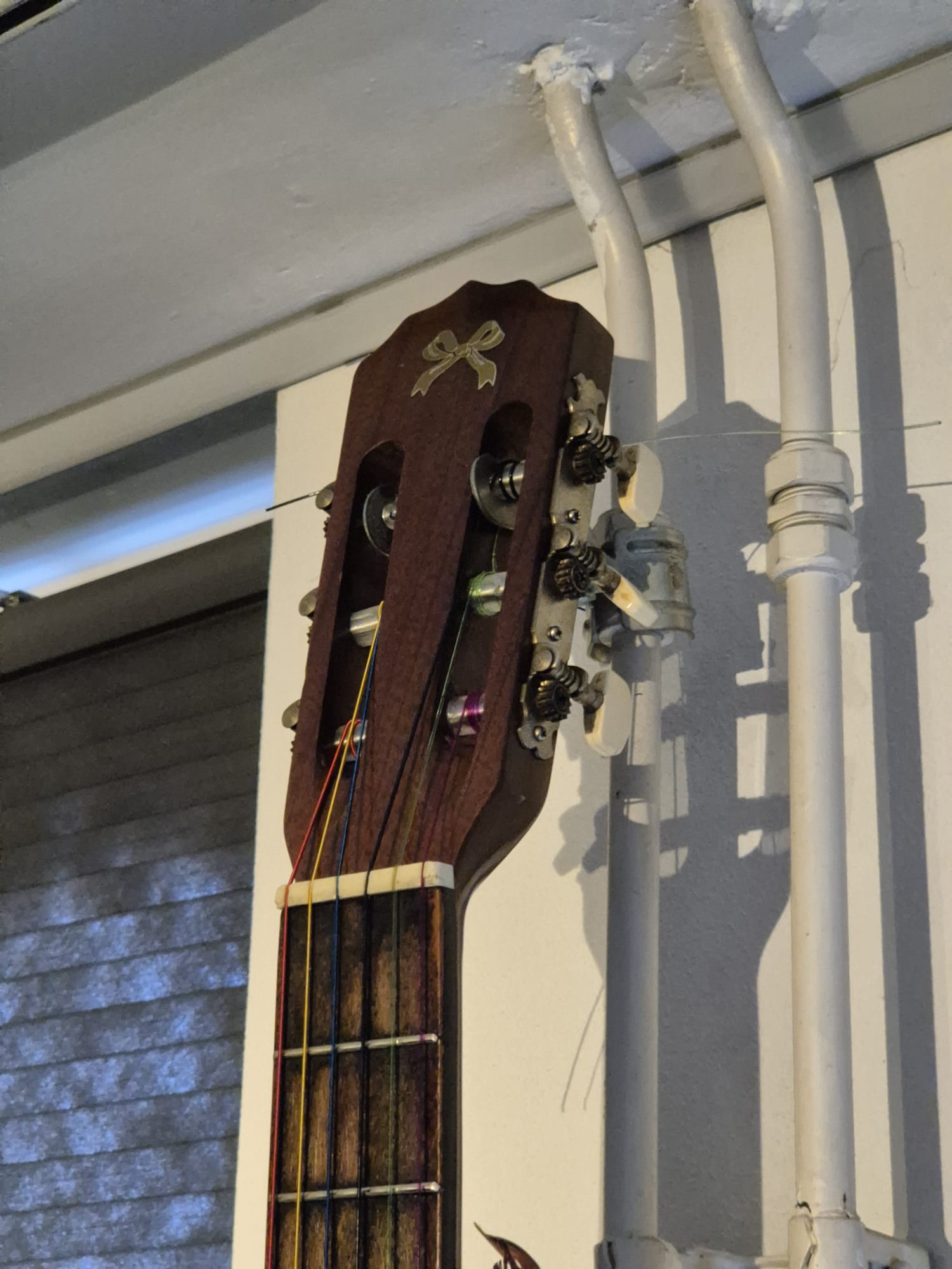
//======================================================================================================================================================
void rollinghumidEN()
{
int Stemp = dht.readHumidity();// Get data from the temp and humid sensor
String Stotal=” The relative humidity is “+String(Stemp)+” percent,”; //define the humid string to be rolled
runscreen(Stotal);
}
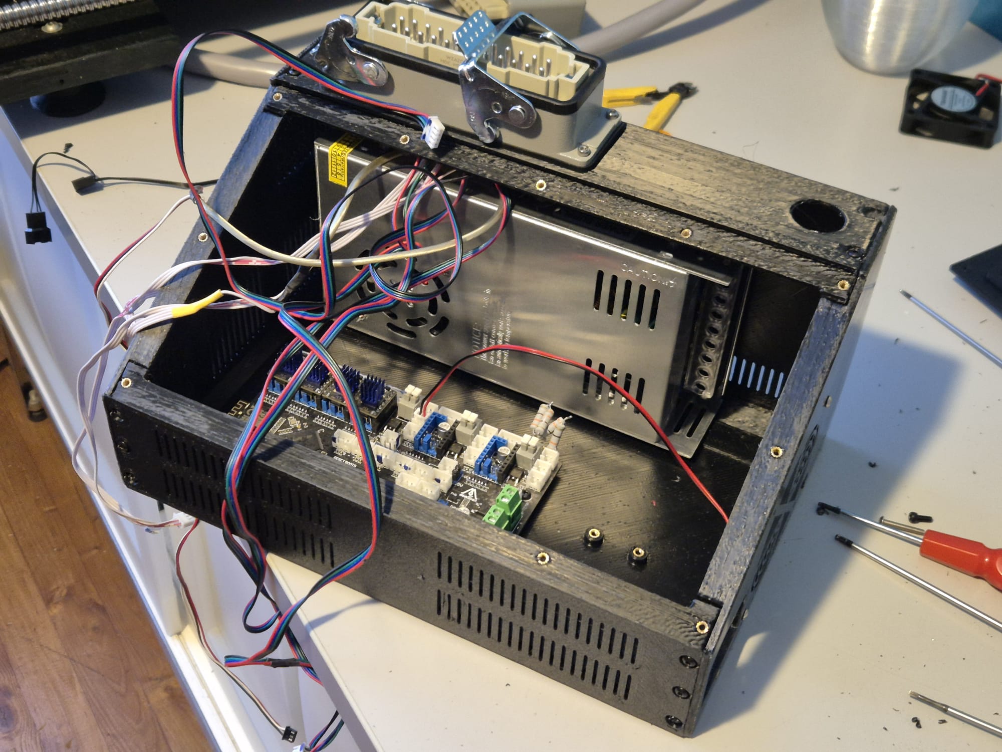
//======================================================================================================================================================
void rollingTempENF()
{
float temperature = 32+ (1.8*(bmp085GetTemperature(bmp085ReadUT()))); // calculate to Fahrenheit= ((Celsius x 1.8) + 32)

String Stotal= ” the temperature is ” + String(temperature,1)+ ” degrees Fahrenheit,” ; //define the string to be rolled
runscreen (Stotal);
}
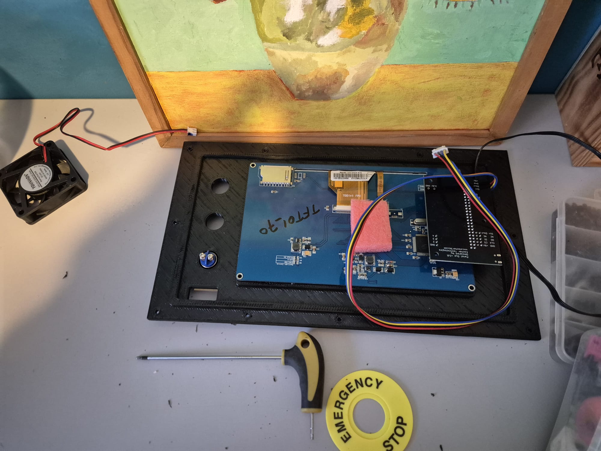
//======================================================================================================================================================
void rollingTempENC()
{
float temperature = bmp085GetTemperature(bmp085ReadUT()); // Celsius

String Stotal= ” (” + String(temperature,1)+ ” degrees Celsius),” ; //define the string to be rolled
runscreen (Stotal);
}
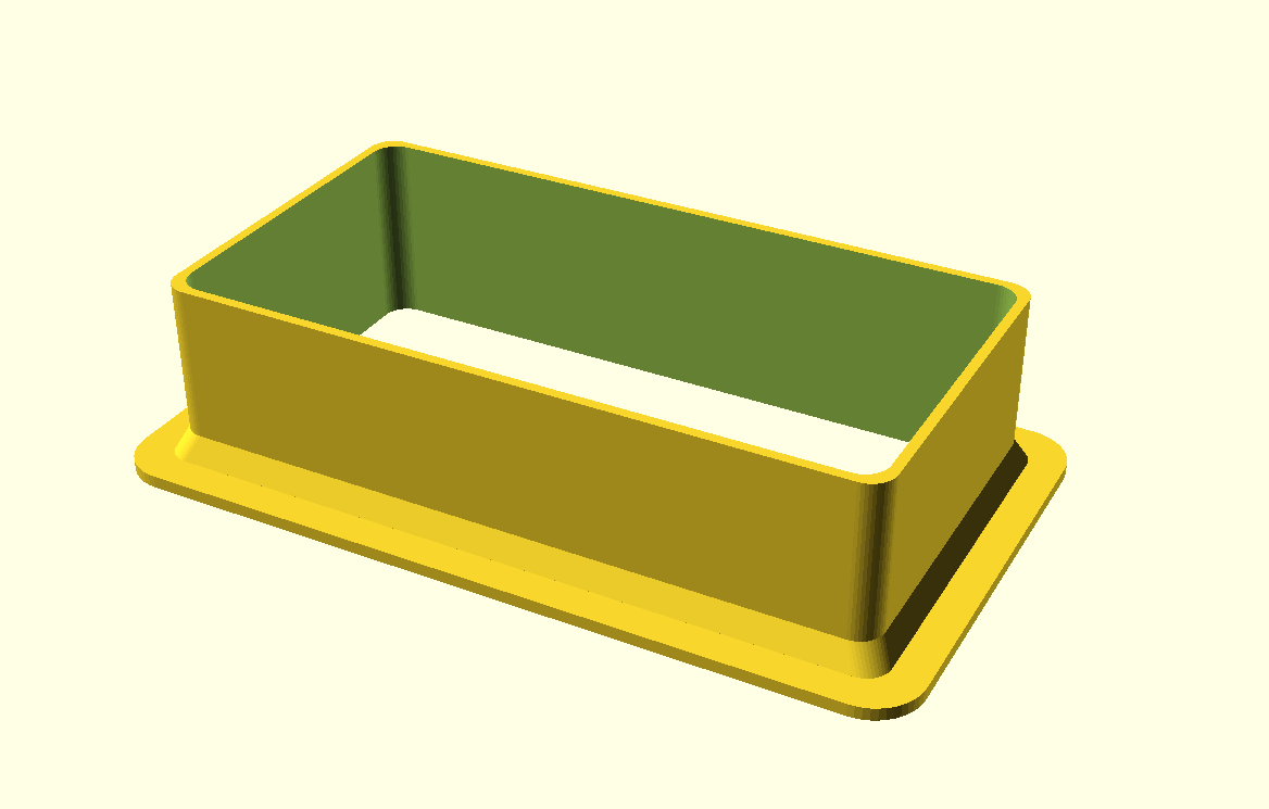
//======================================================================================================================================================
void rollingPressureEN()
{
float pressure = bmp085GetPressure(bmp085ReadUP()); // 100 pascal = 1 millibar
float pressure2 = float (pressure/100);
String Stotal= ” the airpressure is ” + String(pressure2) + ” hPa,”; //define the string to be rolled
runscreen (Stotal);
}
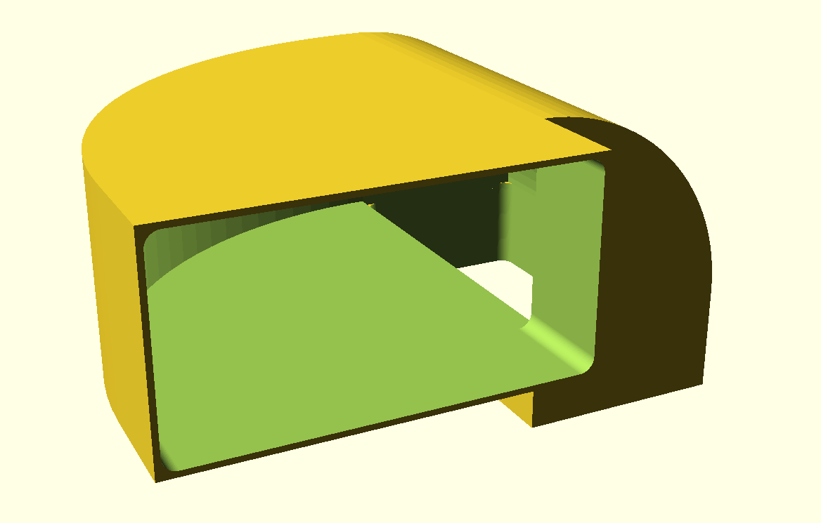
//======================================================================================================================================================
void rollingHeightEN()
{
float pressure = (bmp085GetPressure(bmp085ReadUP())/100); // 100 pascal = 1 millibar
int altitude = calcAltitude(pressure*100); //Uncompensated calculation – in Meters
String Stotal= ” the fictive height is ” + String (altitude) + ” meters “; //define the string to be rolled
runscreen (Stotal);
}

//======================================================================================================================================================
// Stores all of the bmp085’s calibration values into global variables
// Calibration values are required to calculate temp and pressure
// This function should be called at the beginning of the program
void bmp085Calibration()
{
ac1 = bmp085ReadInt(0xAA);
ac2 = bmp085ReadInt(0xAC);
ac3 = bmp085ReadInt(0xAE);
ac4 = bmp085ReadInt(0xB0);
ac5 = bmp085ReadInt(0xB2);
ac6 = bmp085ReadInt(0xB4);
b1 = bmp085ReadInt(0xB6);
b2 = bmp085ReadInt(0xB8);
mb = bmp085ReadInt(0xBA);
mc = bmp085ReadInt(0xBC);
md = bmp085ReadInt(0xBE);
}

// Calculate temperature in deg C
float bmp085GetTemperature(unsigned int ut){
long x1, x2;

x1 = (((long)ut – (long)ac6)*(long)ac5) >> 15;
x2 = ((long)mc << 11)/(x1 + md);
b5 = x1 + x2;

float temp = ((b5 + 8)>>4);
temp = temp /10;

return temp;
}

// Calculate pressure given up
// calibration values must be known
// b5 is also required so bmp085GetTemperature(…) must be called first.
// Value returned will be pressure in units of Pa.
long bmp085GetPressure(unsigned long up){
long x1, x2, x3, b3, b6, p;
unsigned long b4, b7;

b6 = b5 – 4000;
// Calculate B3
x1 = (b2 * (b6 * b6)>>12)>>11;
x2 = (ac2 * b6)>>11;
x3 = x1 + x2;
b3 = (((((long)ac1)*4 + x3)<<OSS) + 2)>>2;

// Calculate B4
x1 = (ac3 * b6)>>13;
x2 = (b1 * ((b6 * b6)>>12))>>16;
x3 = ((x1 + x2) + 2)>>2;
b4 = (ac4 * (unsigned long)(x3 + 32768))>>15;

b7 = ((unsigned long)(up – b3) * (50000>>OSS));
if (b7 < 0x80000000)
p = (b7<<1)/b4;
else
p = (b7/b4)<<1;

x1 = (p>>8) * (p>>8);
x1 = (x1 * 3038)>>16;
x2 = (-7357 * p)>>16;
p += (x1 + x2 + 3791)>>4;

long temp = p;
return temp;
}

// Read 1 byte from the BMP085 at ‘address’
char bmp085Read(unsigned char address)
{
unsigned char data;

Wire.beginTransmission(BMP085_ADDRESS);
Wire.write(address);
Wire.endTransmission();

Wire.requestFrom(BMP085_ADDRESS, 1);
while(!Wire.available())
;

return Wire.read();
}

// Read 2 bytes from the BMP085
// First byte will be from ‘address’
// Second byte will be from ‘address’+1
int bmp085ReadInt(unsigned char address)
{
unsigned char msb, lsb;

Wire.beginTransmission(BMP085_ADDRESS);
Wire.write(address);
Wire.endTransmission();

Wire.requestFrom(BMP085_ADDRESS, 2);
while(Wire.available()<2)
;
msb = Wire.read();
lsb = Wire.read();

return (int) msb<<8 | lsb;
}

// Read the uncompensated temperature value
unsigned int bmp085ReadUT(){
unsigned int ut;

// Write 0x2E into Register 0xF4
// This requests a temperature reading
Wire.beginTransmission(BMP085_ADDRESS);
Wire.write(0xF4);
Wire.write(0x2E);
Wire.endTransmission();

// Wait at least 4.5ms
delay(5);

// Read two bytes from registers 0xF6 and 0xF7
ut = bmp085ReadInt(0xF6);
return ut;
}

// Read the uncompensated pressure value
unsigned long bmp085ReadUP(){

unsigned char msb, lsb, xlsb;
unsigned long up = 0;

// Write 0x34+(OSS<<6) into register 0xF4
// Request a pressure reading w/ oversampling setting
Wire.beginTransmission(BMP085_ADDRESS);
Wire.write(0xF4);
Wire.write(0x34 + (OSS<<6));
Wire.endTransmission();

// Wait for conversion, delay time dependent on OSS
delay(2 + (3<<OSS));

// Read register 0xF6 (MSB), 0xF7 (LSB), and 0xF8 (XLSB)
msb = bmp085Read(0xF6);
lsb = bmp085Read(0xF7);
xlsb = bmp085Read(0xF8);

up = (((unsigned long) msb << 16) | ((unsigned long) lsb << 8) | (unsigned long) xlsb) >> (8-OSS);

return up;
}
// xxxxxxxxxxxxxxxxxxxxxxxxxxxxxxxxxxxxxxxxxxxxxxxxxxxxxxxxxxxxxxxxxxxxxxxxxxxxxxxxxxxxxxxxxxxxxxxxxxxxxxxxxxxxxxxxxxxxxxx
void writeRegister(int deviceAddress, byte address, byte val)
{
Wire.beginTransmission(deviceAddress); // start transmission to device
Wire.write(address); // send register address
Wire.write(val); // send value to write
Wire.endTransmission(); // end transmission
}

int readRegister(int deviceAddress, byte address){

int v;
Wire.beginTransmission(deviceAddress);
Wire.write(address); // register to read
Wire.endTransmission();

Wire.requestFrom(deviceAddress, 1); // read a byte

while(!Wire.available()) {
// waiting
}

v = Wire.read();
return v;
}

float calcAltitude(float pressure){

float A = pressure/101325;
float B = 1/5.25588;
float C = pow(A,B);
C = 1 – C;
C = C /0.0000225577;

return C;
}

//XXXXXXXXXXXXXXXXXXXXXXXXXXXXXXXXXXXXXXXXXXXXXXXXXXXXXXXXXXXXXXXXXXXXXXXXXXXXXXXXXXXXXXXXXXXXXXXXXXXXXXXXXXXXXXXXXXXXXXXXXXXXXXXXXXXXXXXXXXXXXXXXXXX
void switches()
/* the intent here is to use a couple of hardware switches to set all parameters of the system, so you don’t need to update it with the PC.
The systems becomes independent in this way and possibly it can be a sellable item then.

There will be 3 switches: Select , Up and Down. If there is enough room, I will connect them all three to available inputs:
A1= Select,
D9= Up and
D7= Down

The structure is for Select to halt the running programs through the interrupt that is built in the wait void!
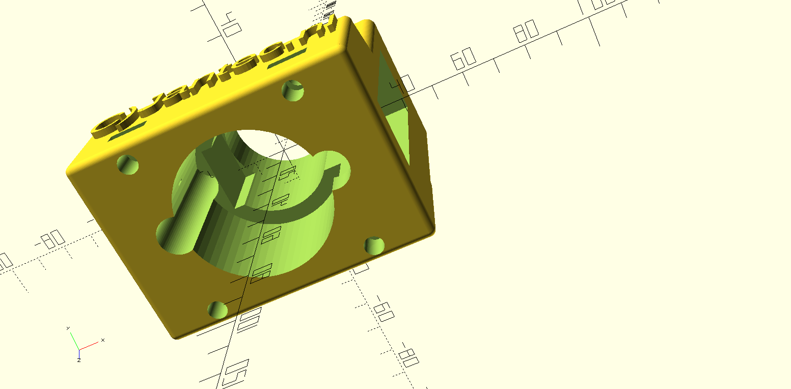
Once you are in the switches void the structure is to g through setup with Up and Down, choose the appropriate setting ans Select is, after which you
can again select a new option if available and so on.

I will try to make a function that allows you to press Up and Down at the same time to return immediately or to use is as a reset possibility…

Up and down could also be used as up/down time/date/others by pressing where long press fastens the speed of change…
*/

{

//main menu select main functions 1 clock set,2 date set,3 language,4 speed,5 appearance: short/long/playfull,6 priority : more time/ more weather/ more fun, 7 update
// this variable used to store these switches is integer: MainMenu (1-7)
// The choices will be stored in the available flash memory of the DS 1307 so that the system will always restart with the active last settings
// Only the first 8 bytes (0x00 – 0x07) are used by the clock itself while the other 56 bytes can be used as scratchpad RAM, BUT.. on this small board there
// is also 32K of memory available in a small AT24C32 separately addressable Eprom memory!
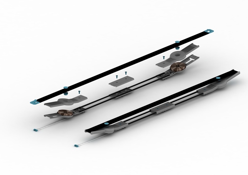
Select=false; // reset state of Reset button to start

// this is the 1st loop to input and setup
clearscreen();

writescreensmall(” press a”, ” button “, 0);

// delay(5000);

//wait for press on Up, Down or Select
while(1)
{
int valU = digitalRead(UpPIN); // read the input pin
if (valU==LOW) {Up=true; break;} // // if key Up is pressed set a binary state high here
int valD = digitalRead(DownPIN); // read the input pin
if (valD==LOW) {Down=true; break;} // if key Down is pressed set a binary state high here
// int valS = digitalRead(SelectPIN); // read the input pin
// if (valS==LOW) {Select=true; break;} // if key Select is pressed set a binary state high here
}
clearscreen();
//xxxxxxxxxxxxxxxxxxxxxxxxxxxxxxxxxxxxxx

if (Up==true){
Up=false;
// this is the 2nd loop to input and setup
clearscreen();
writescreensmall(” time “, “settings”,0);
delay(2000);

//wait for press on Up or Down
while(1)
{
int valU = digitalRead(UpPIN); // read the input pin
if (valU==LOW) {Up=true; break;} // // if key Up is pressed set a binary state high here
int valD = digitalRead(DownPIN); // read the input pin
if (valD==LOW) {Down=true; break;} // if key Up is pressed set a binary state high here
int valS = digitalRead(SelectPIN); // read the input pin
if (valS==LOW) {Select=true; break;} // if key Select is pressed set a binary state high here
}
clearscreen();
}

//xxxxxxxxxxxxxxxxxxxxxxxxxxxxxxxxxxxxx

if (Down==true){
Down=false;
// this is the 2nd loop to input and setup
clearscreen();
writescreensmall(” date “, “settings”,0);

delay(2000);

//wait for press on Up or Down
while(1)
{
int valU = digitalRead(UpPIN); // read the input pin
if (valU==LOW) {Up=true; break;} // // if key Up is pressed set a binary state high here
int valD = digitalRead(DownPIN); // read the input pin
if (valD==LOW) {Down=true; break;} // if key Up is pressed set a binary state high here
int valS = digitalRead(SelectPIN); // read the input pin
if (valS==LOW) {Select=true; break;} // if key Select is pressed set a binary state high here
}
clearscreen();
}

//xxxxxxxxxxxxxxxxxxxxxxxxxxxxxxxxxxxxx
if (Select=true) {Select=false; Up=false; Down=false; return;}
if (Up=true) {Up=false; switches();}
if (Down=true) {Down=false; switches();}
//else Select=true, this must be better structured!
//else break;

//xxxxxxxxxxxxxxxxxxxxxxxxxxxxxxxxxxxxx
// write the dataword in memory that will be used after this as settings for all variables, and when restarted read from mem for the same purpose…
// use the mem from the DS1307, extra chip on it with 32Kbit= 4kByte
low=0x00;
byte dataword[]={“05100000000testJMWG”};
//pos 1 (not 0) plus 48 is wait, etcetera…. IT IS an array of chars!
// can be written per character, is simpler than first build an array…

for (int i=0;i<=20;i++)
{
Wire.beginTransmission(0x50);
Wire.write(high);
Wire.write(low);
Wire.write(dataword[i]);
Wire.endTransmission();
delay(5);
low++;
}

//READ the memory of the AT24C32 (just used for debugging)
low=0x00;
// Serial.println();
for (int i=0;i<=20;i++)
{
Wire.beginTransmission(0x50);
Wire.write(high);
Wire.write(low);
Wire.endTransmission();
Wire.requestFrom(0x50 ,1);
char data=Wire.read();
delay(5);
// Serial.print(“DATA “);
// Serial.print(data);
// Serial.print(” LO ADD “);
// Serial.println(low);
// delay(10);
low++;
}

// Serial.println();
// Serial.print(“wait= “);
// Serial.print(wait);

// the values of the settings will be written in AT24C32 register and will be read in Setup void, every time the device (re)starts
// the values are minus 48 due to the caharcter set in memory, ascii table starts at 0 as int48!
// wait, integer between 0 and 9==>8 to 18 (+8) position low 1
// typeofclock, small clock or big clock 0 or 1 position low 2
// fun, with fun or just readouts 0 or 1 position low 3
// minormax, minimum screen or all of it 0 or 1 position low 4

Select=false; // reset state of 3 buttons to start
Up=false; // reset state of 3 buttons to start
Down=false; // reset state of 3 buttons to start

}