LEES DIT ARTIKEL IN HET NEDERLANDS
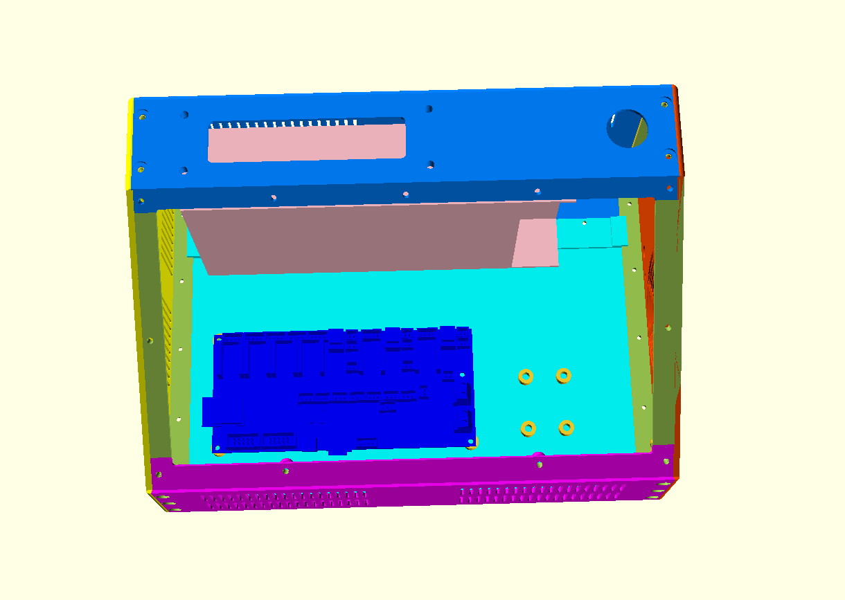
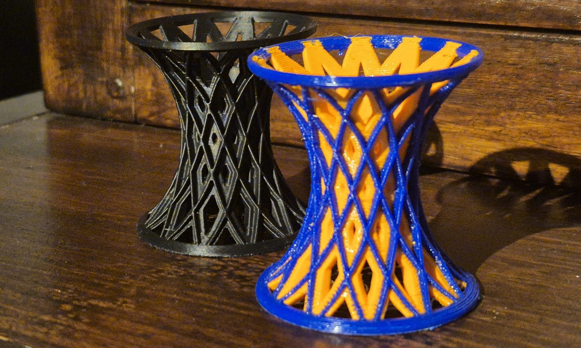
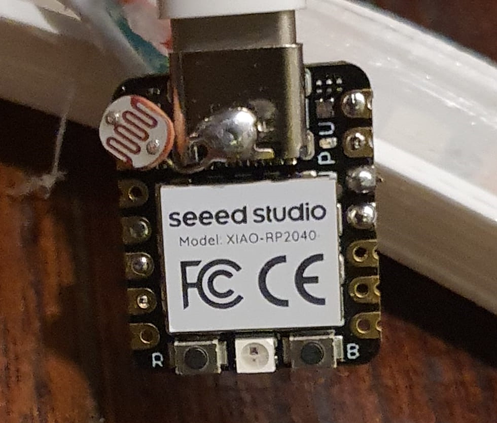
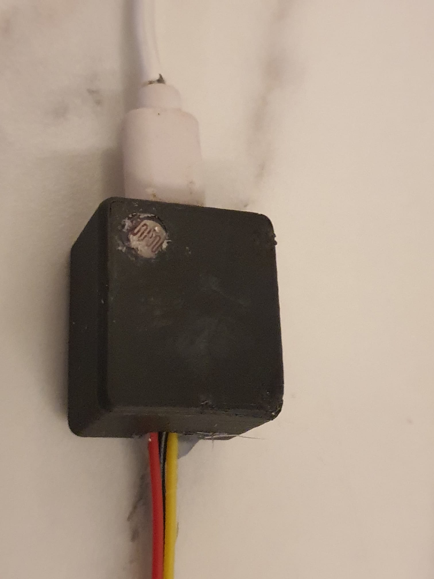
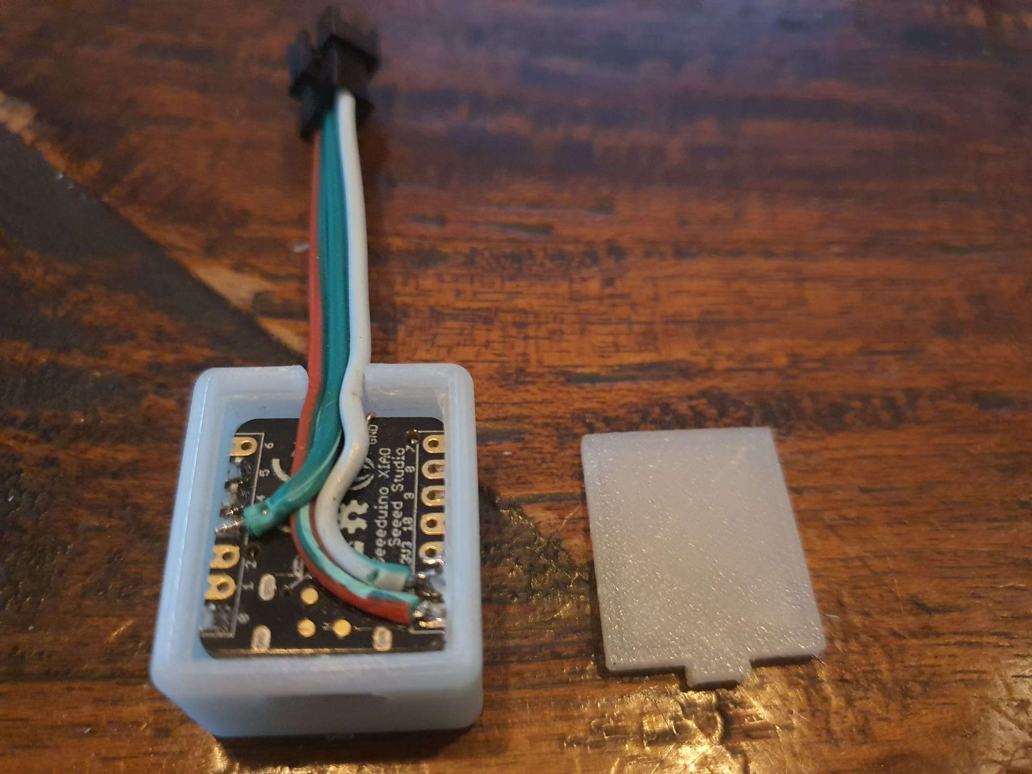
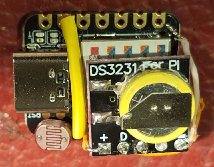
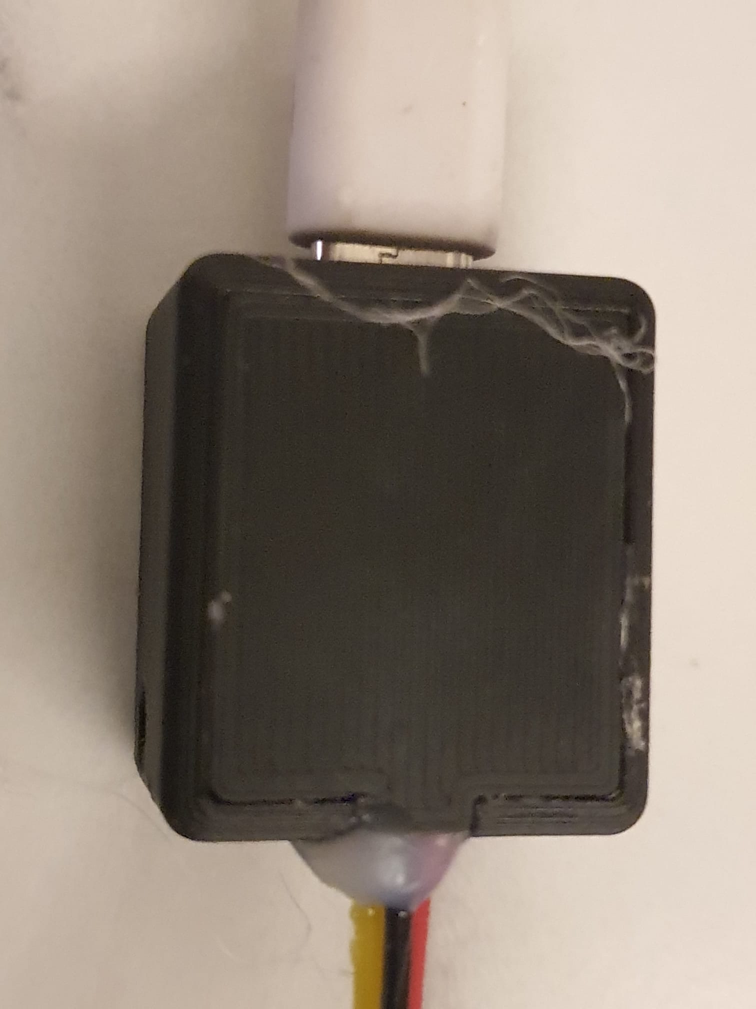
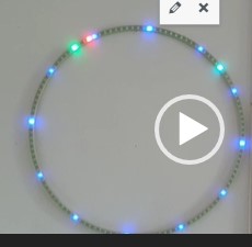
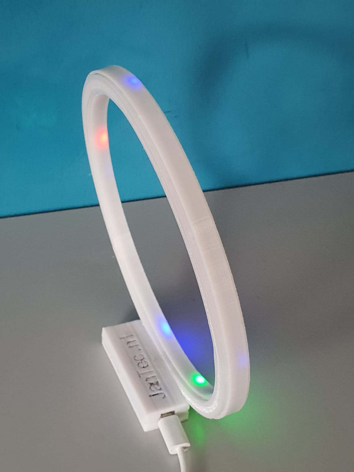
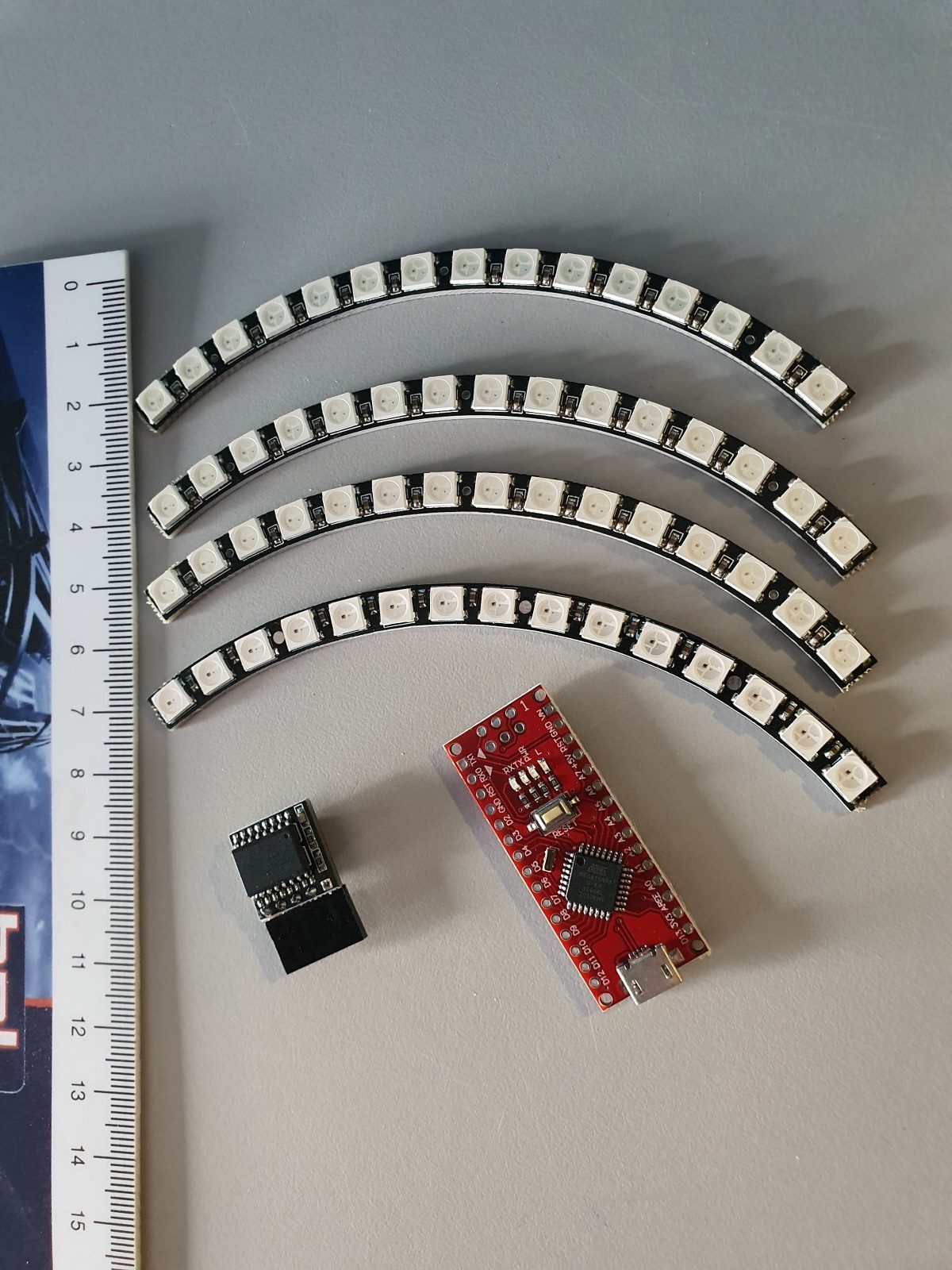
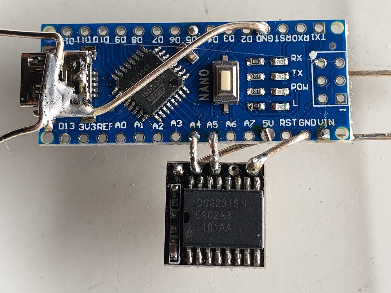
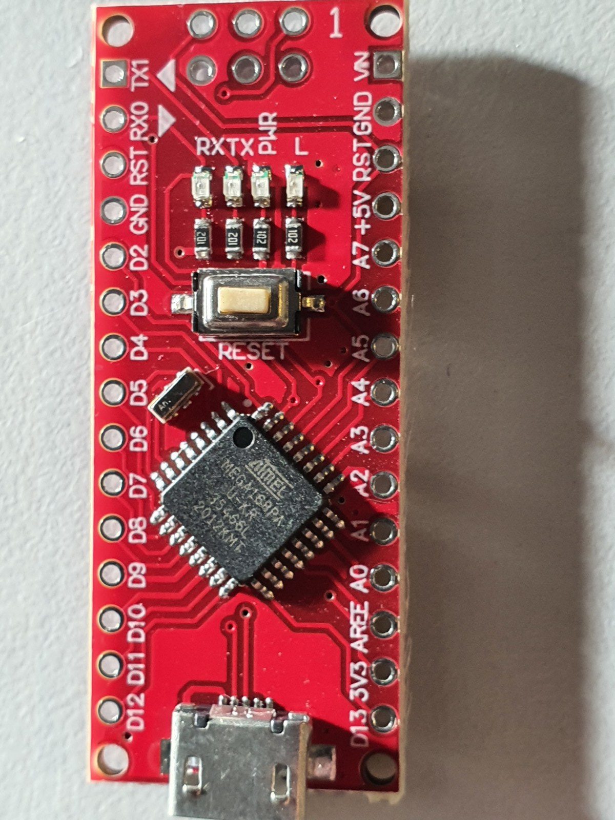
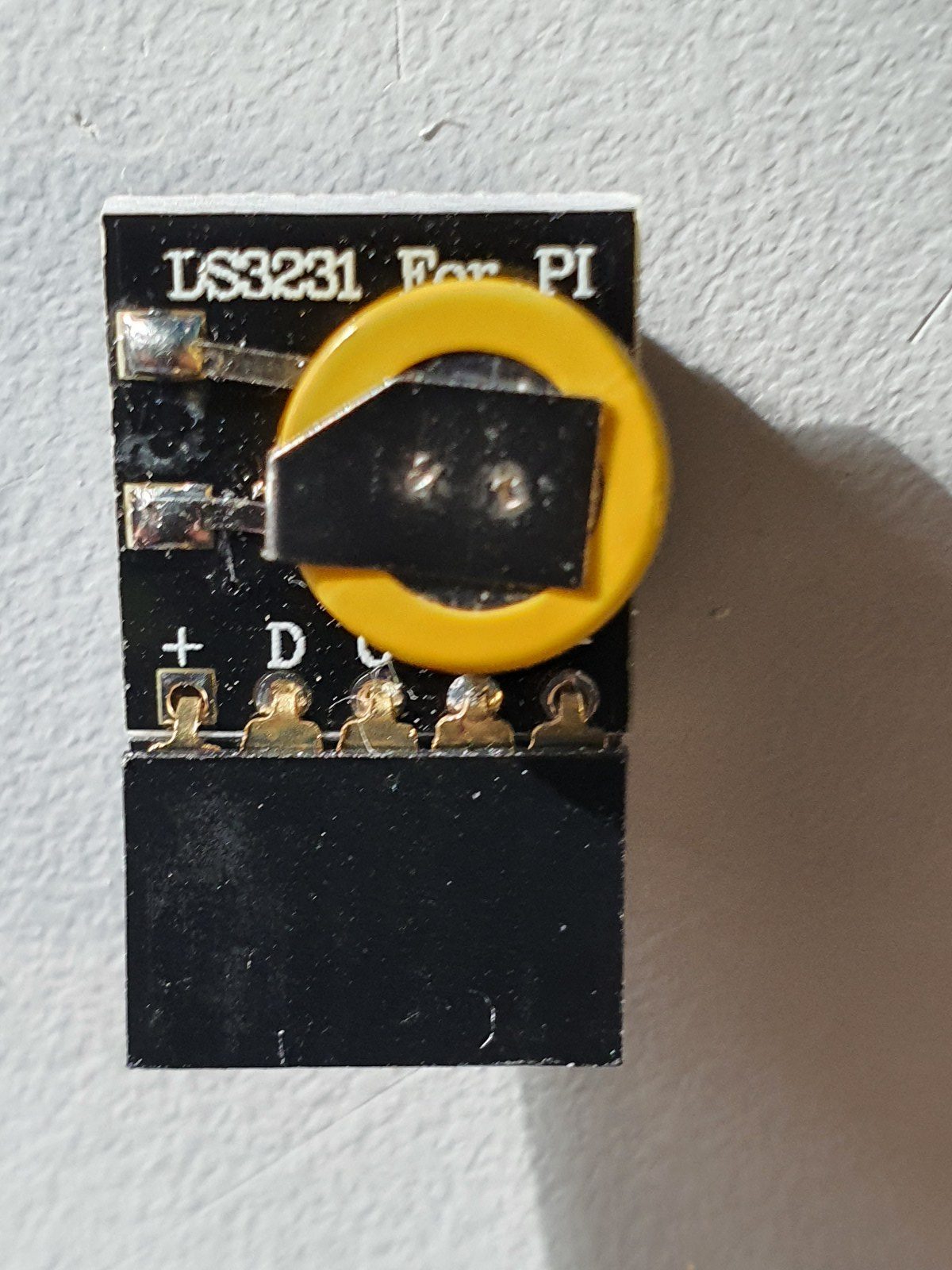
In the above video you see all required parts for the elctronics. An arduino Nano, a time module LS3231 with battery back-up and a 4-parts ring each with 15 WS2812 LED’s that provide a 160mm 60 LED units clock. You can build it as an open built unit as shown above with wire strings or in a 3d printable slim case that I developed. See the pictures below.
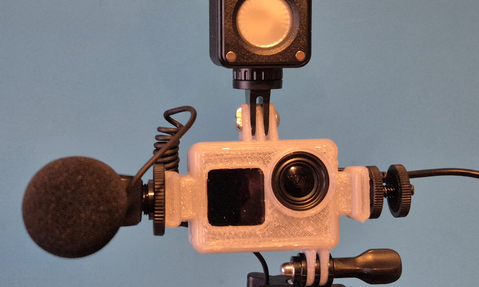
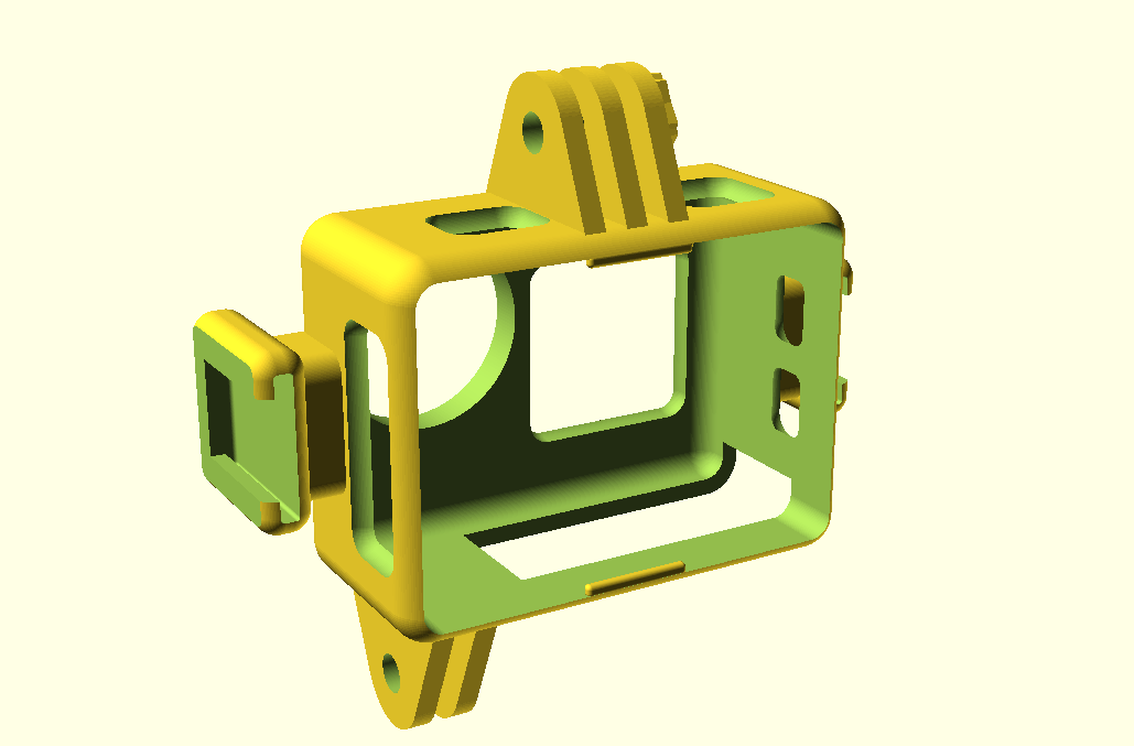
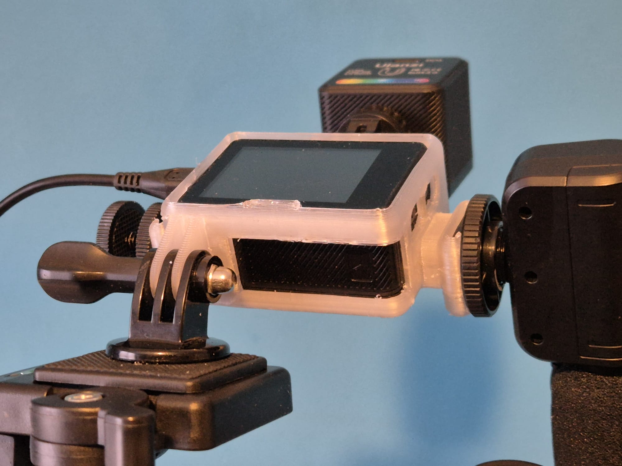
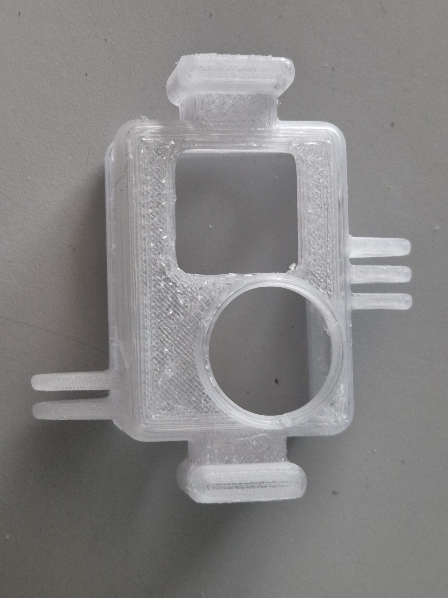
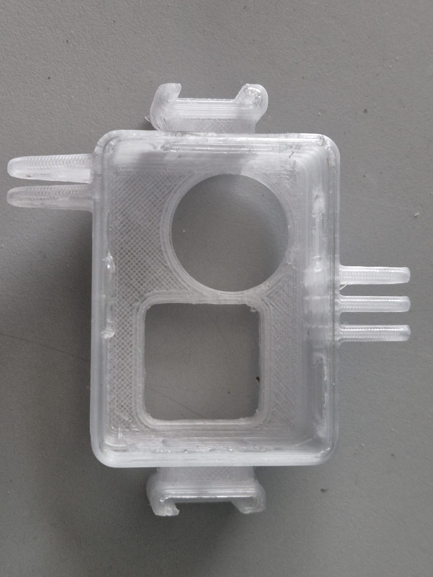
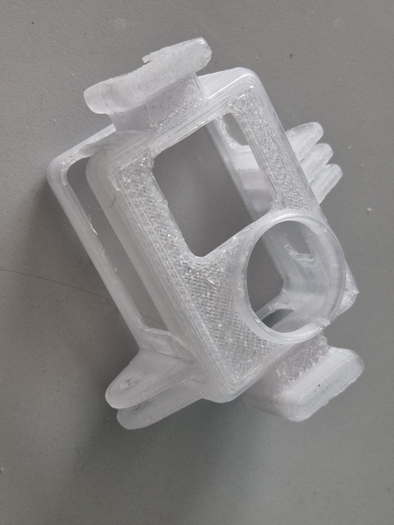
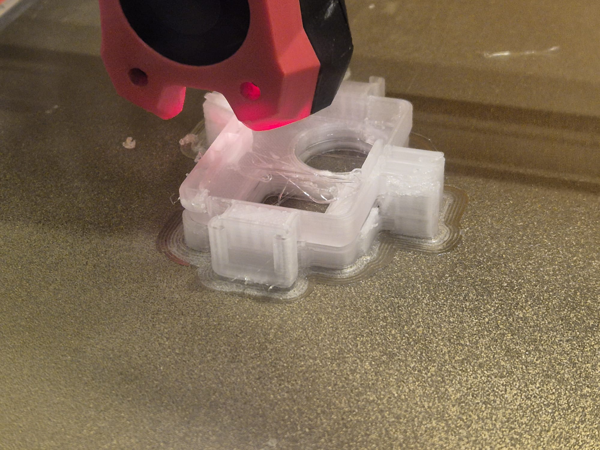
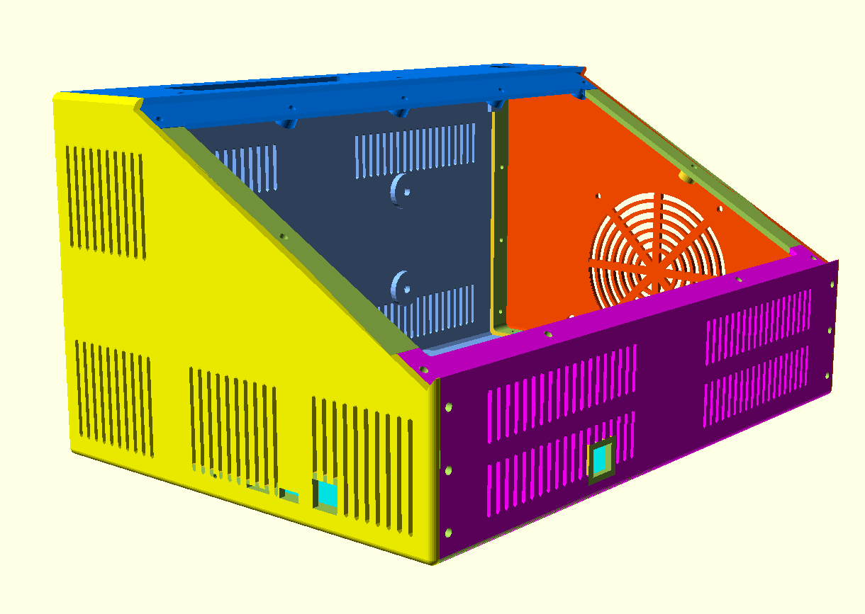
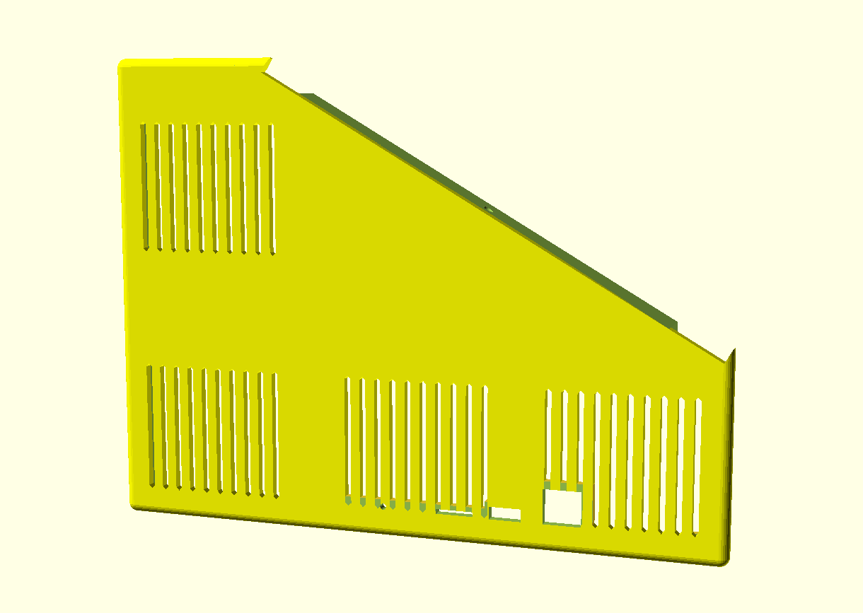
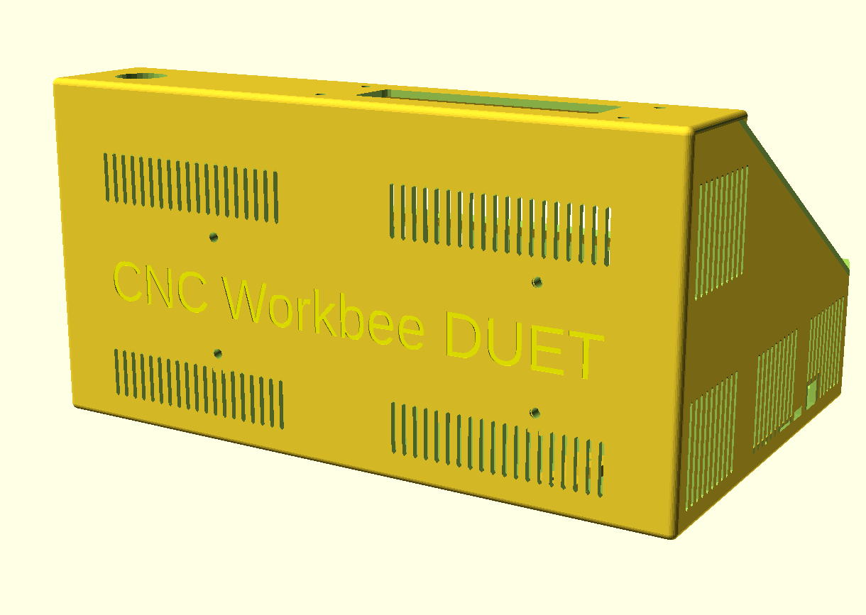
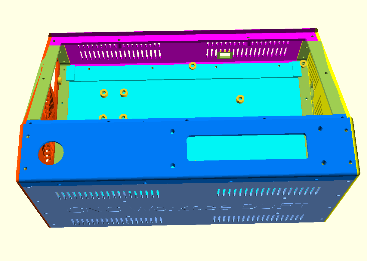
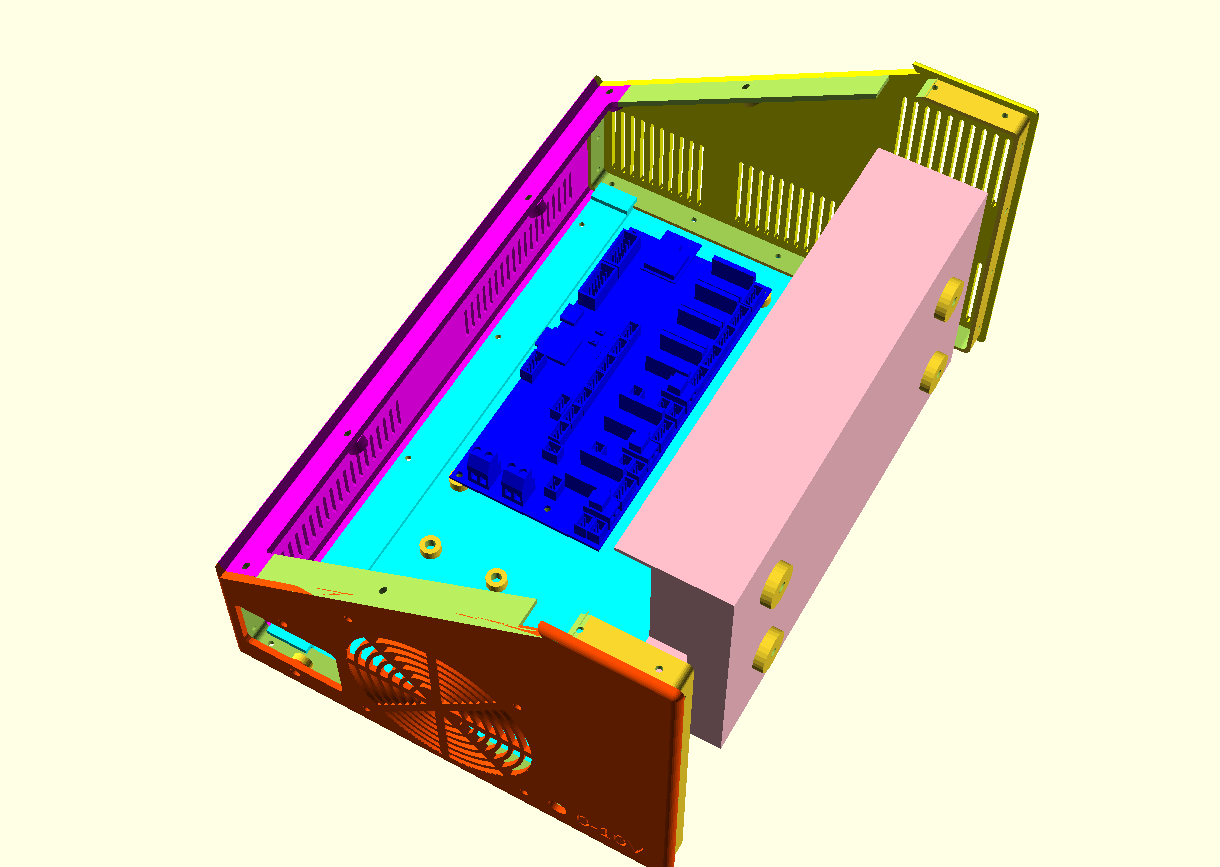
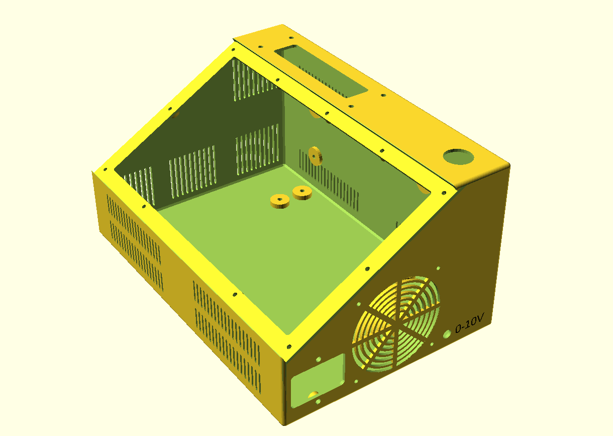
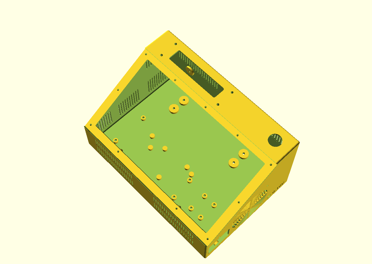
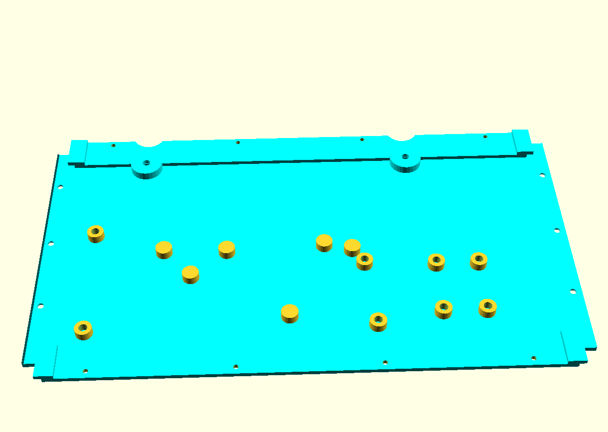
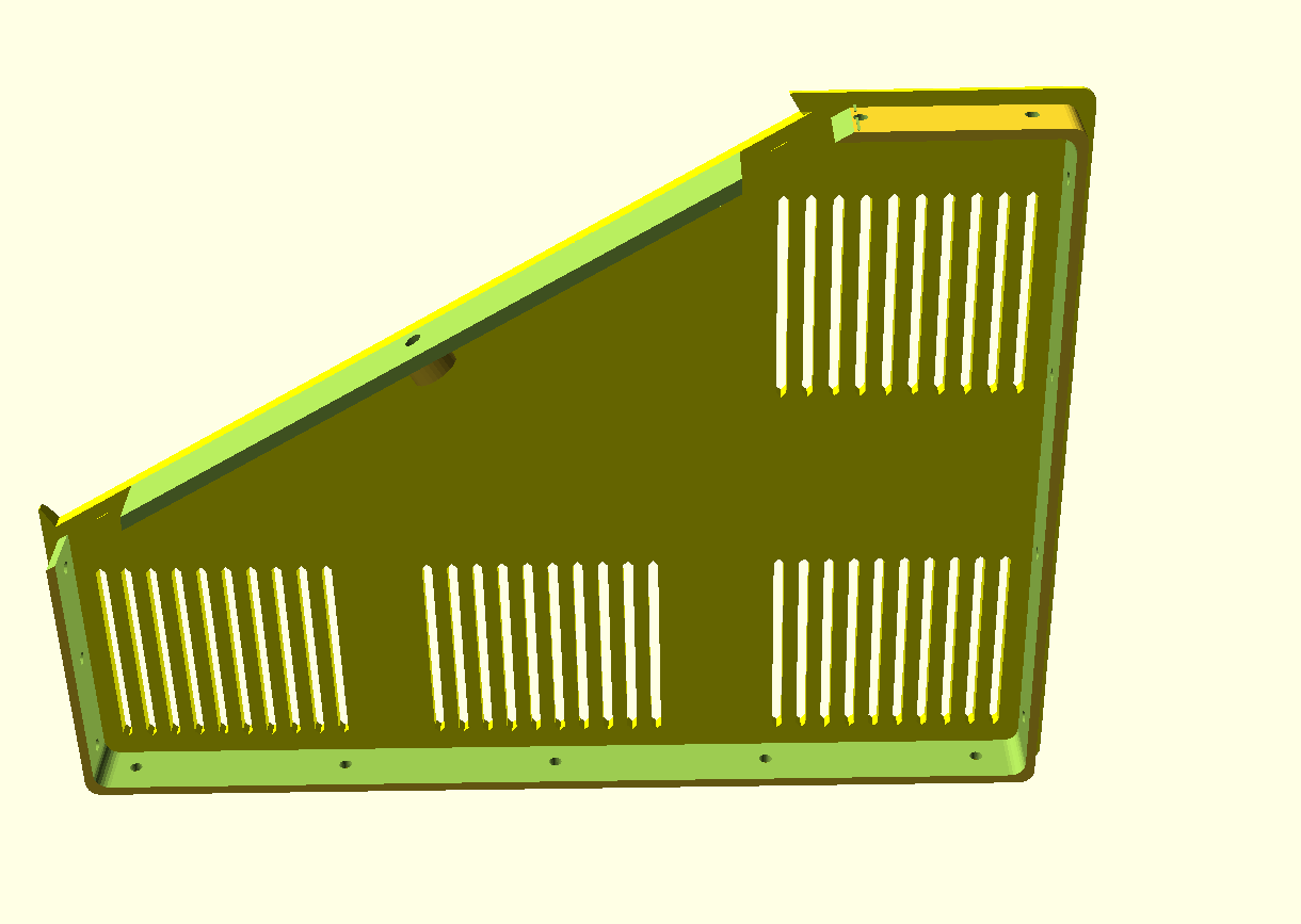
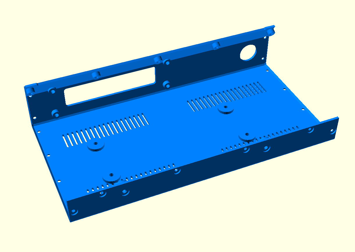
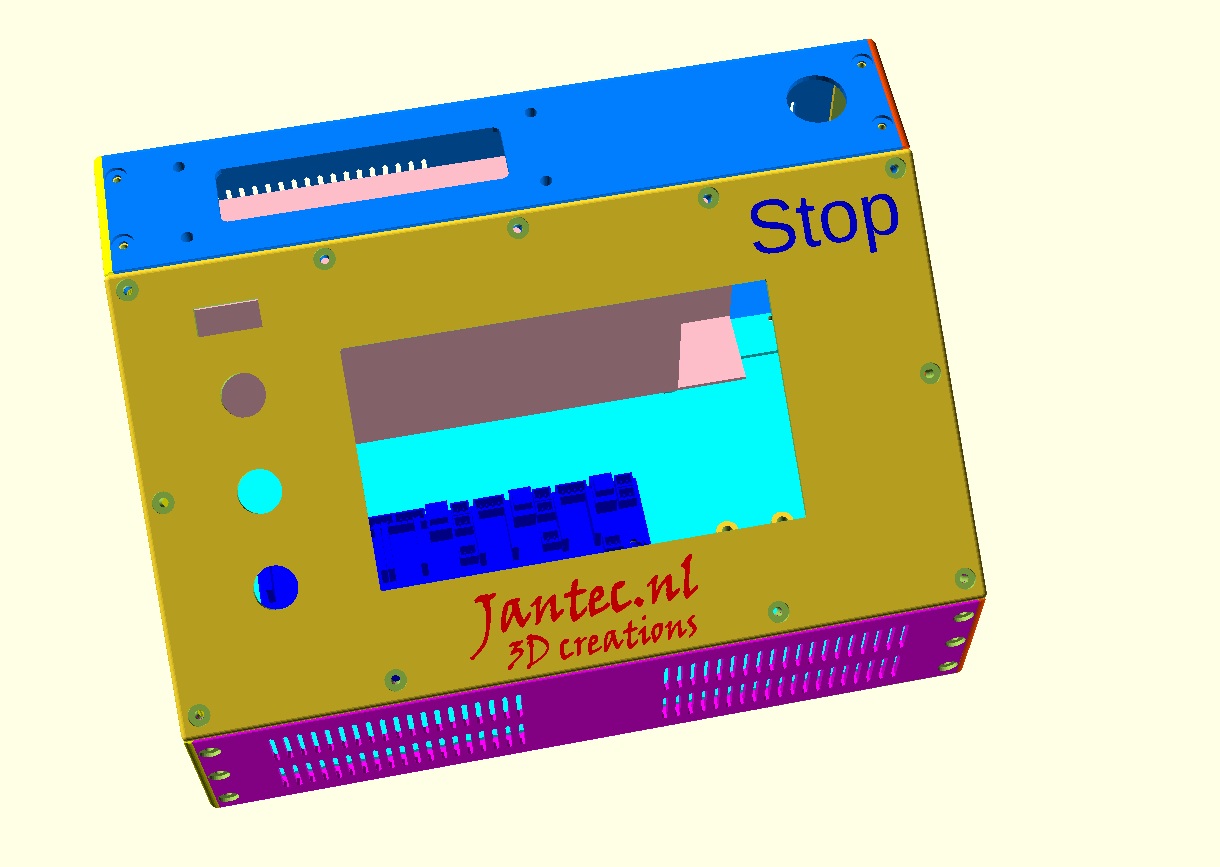
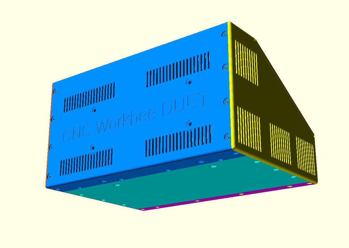
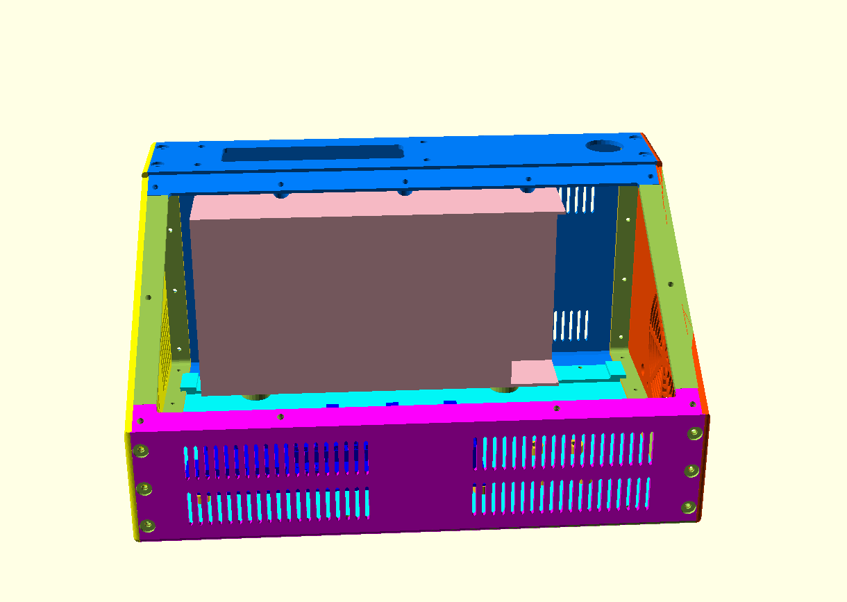
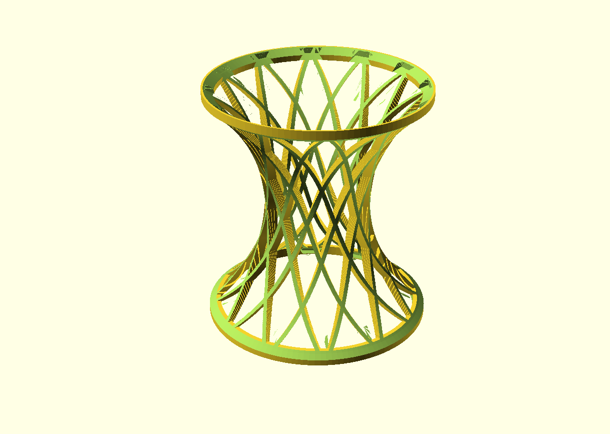
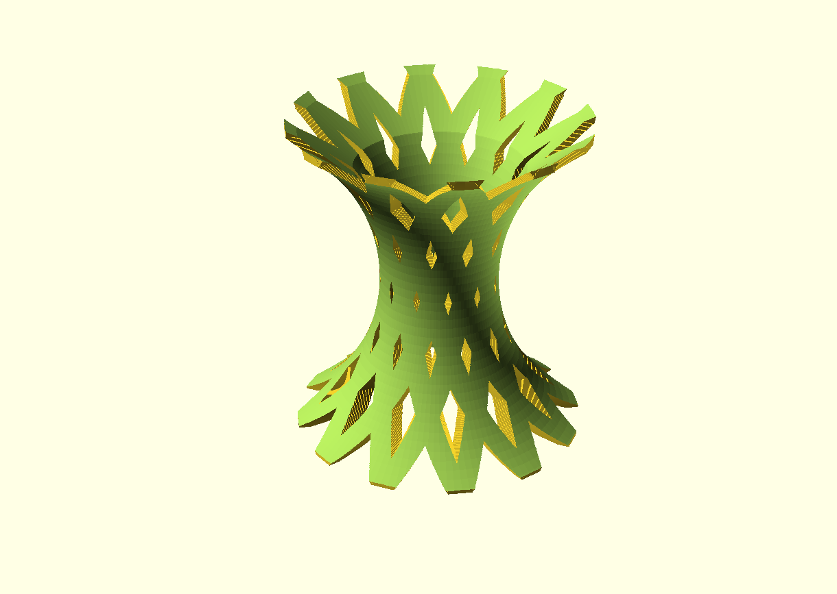
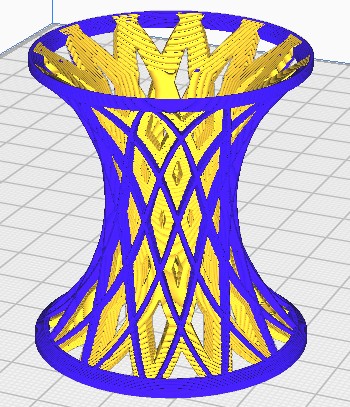
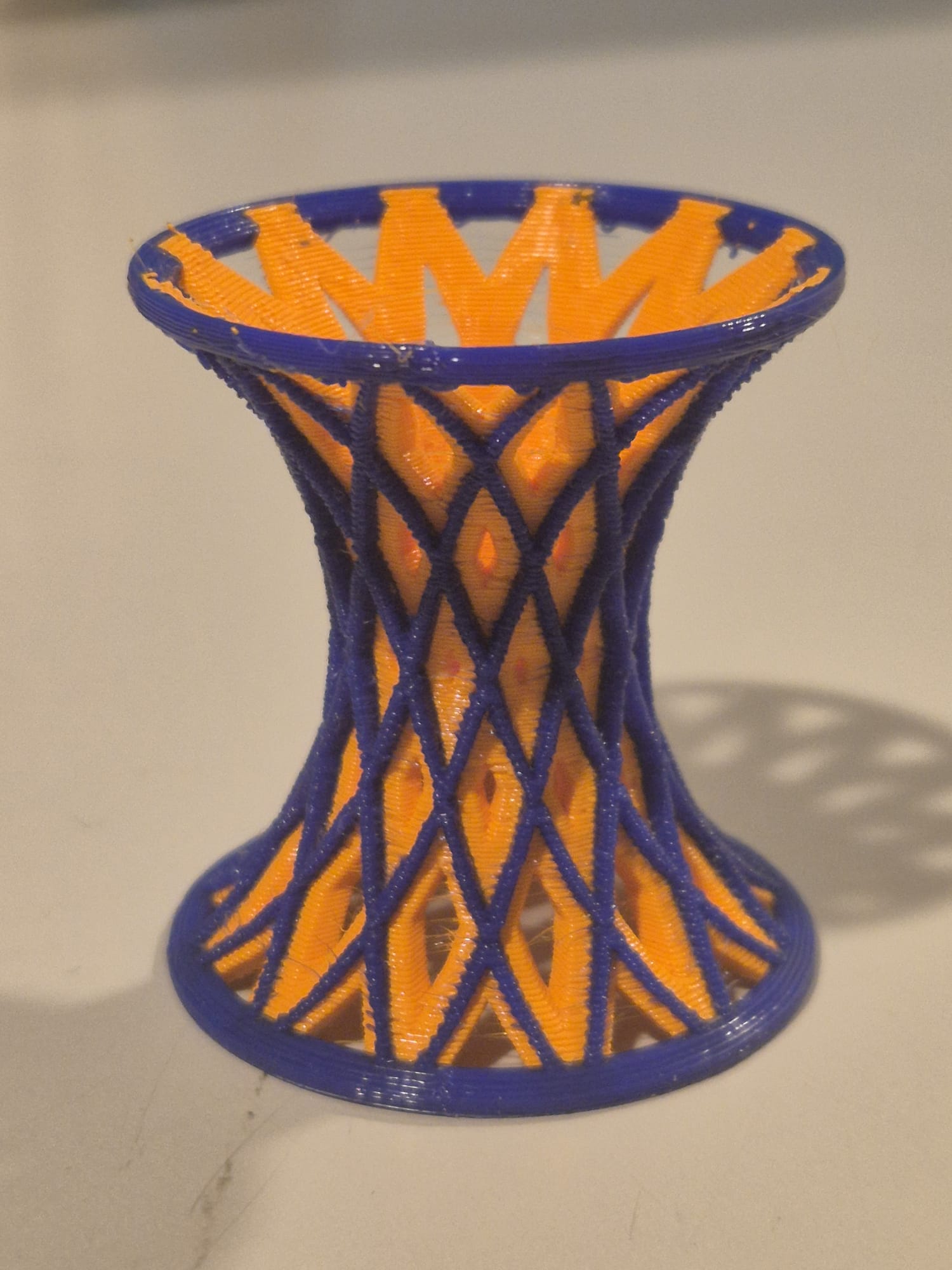
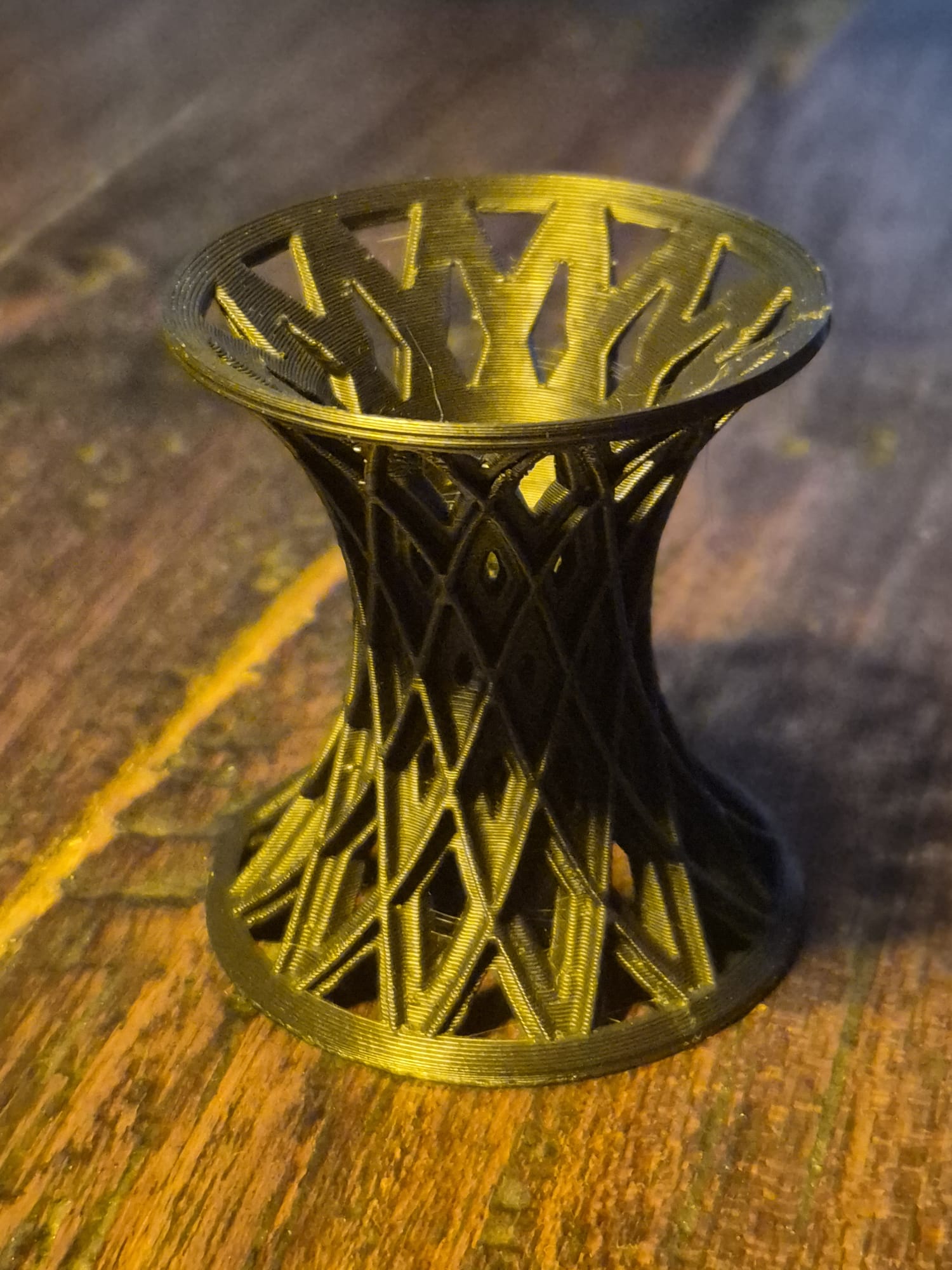
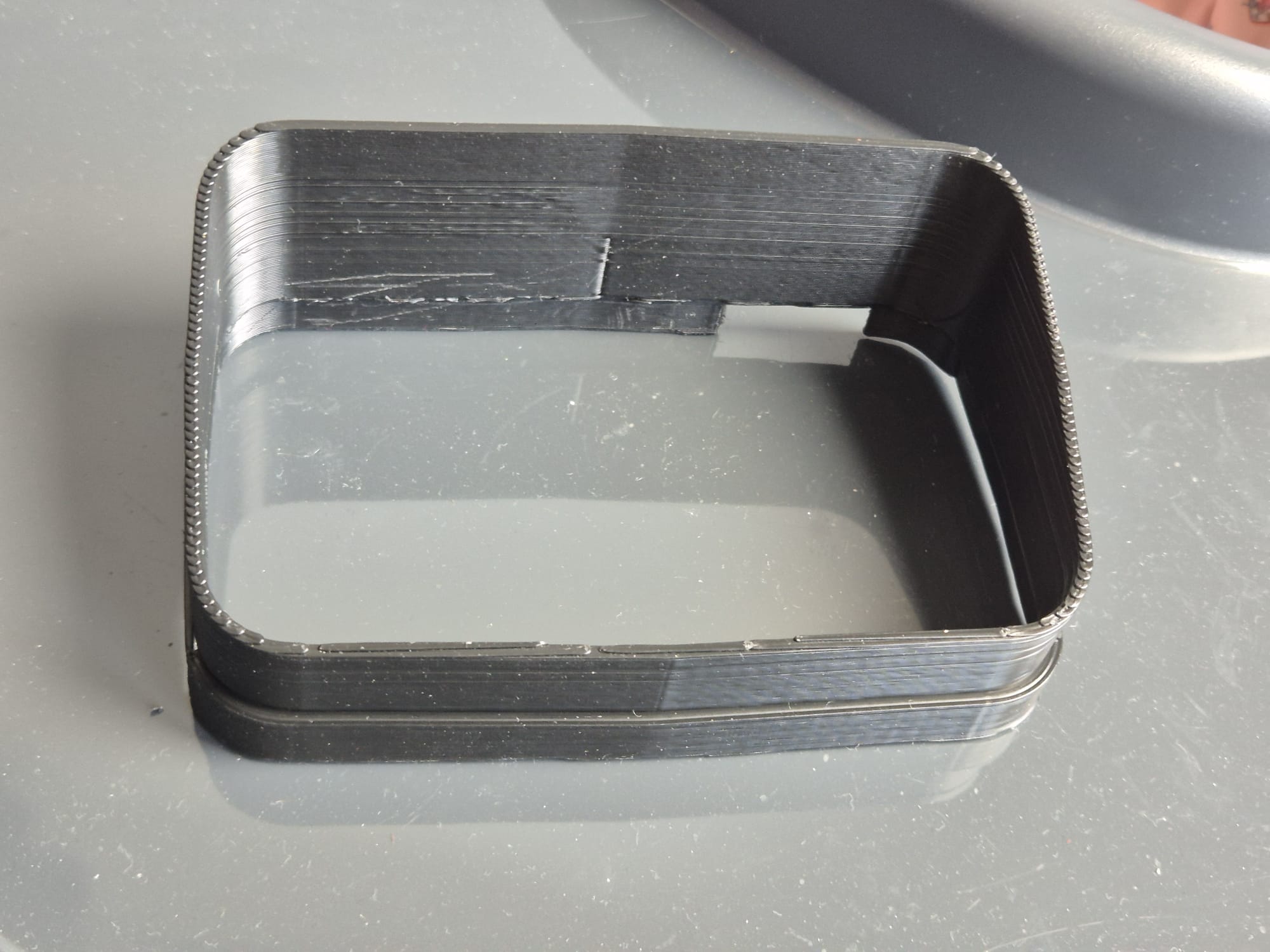
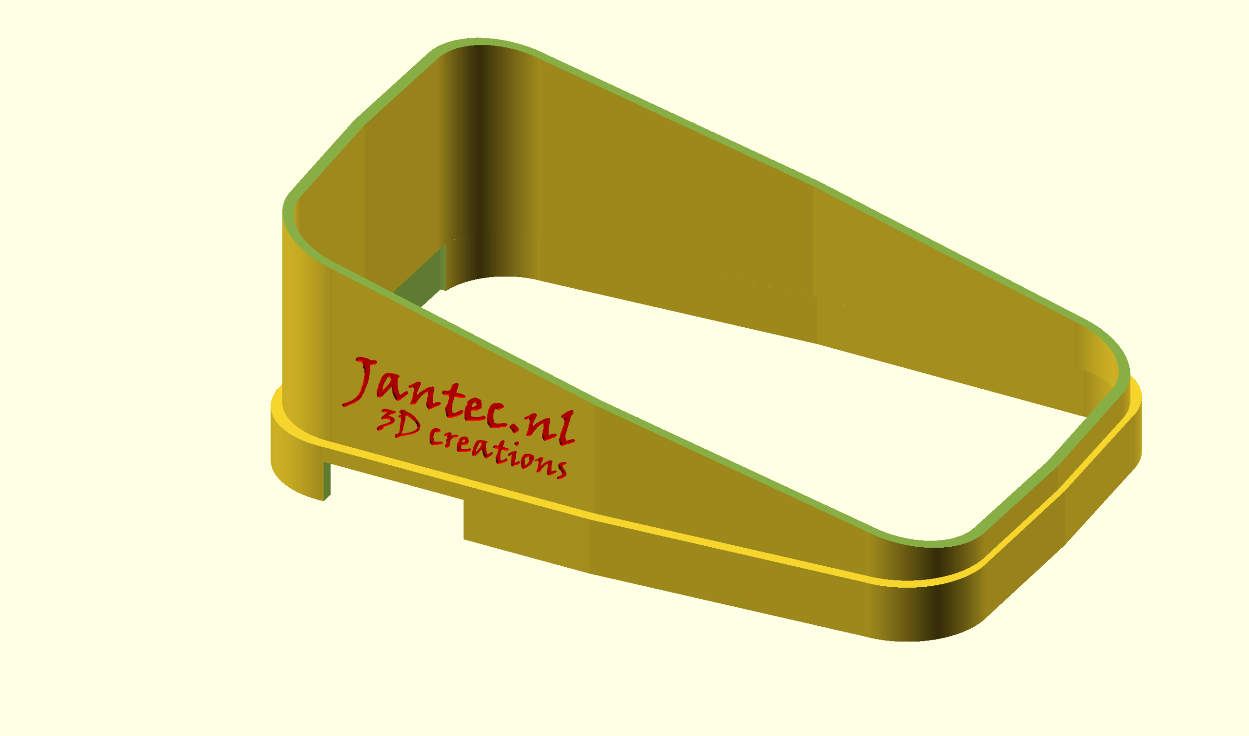
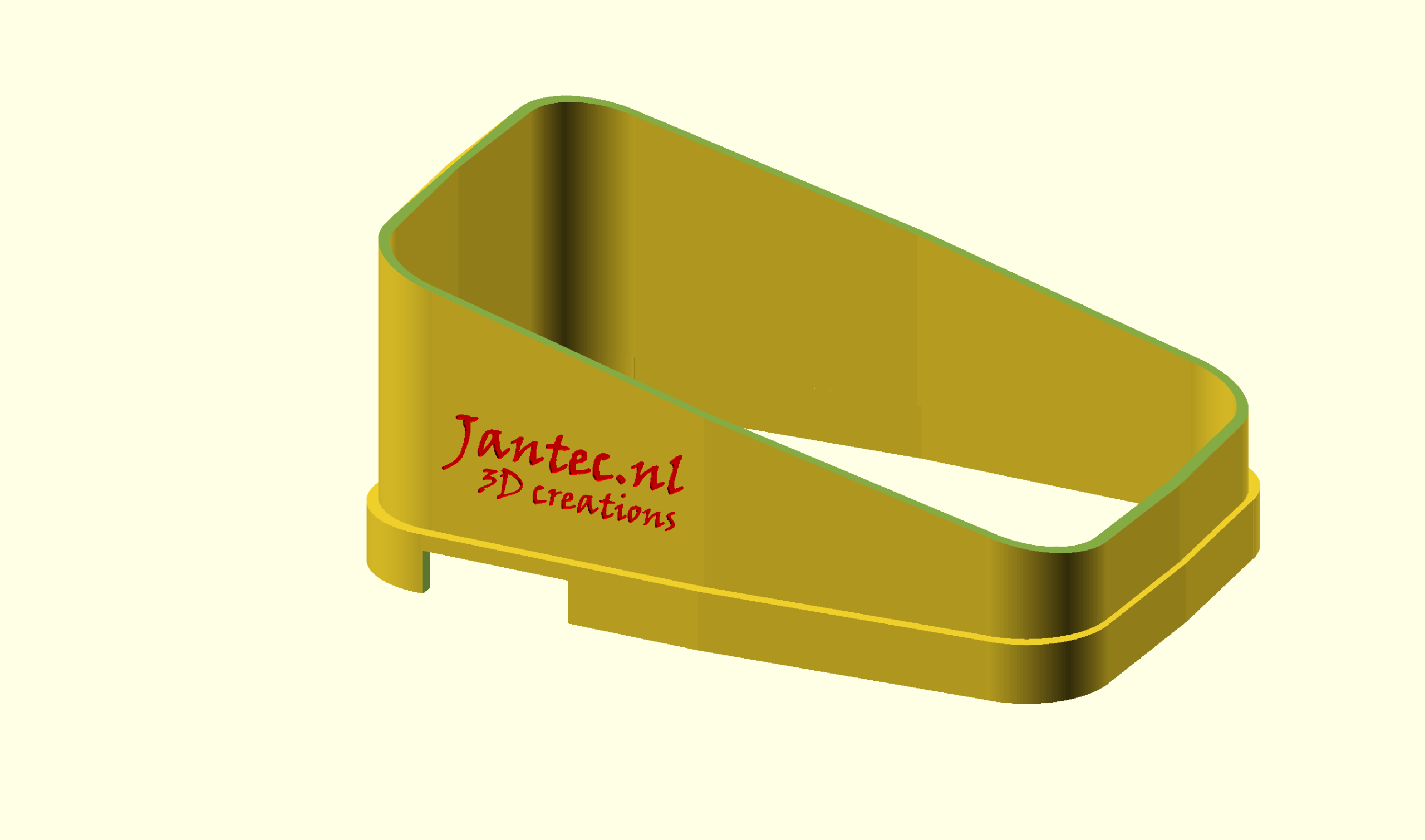
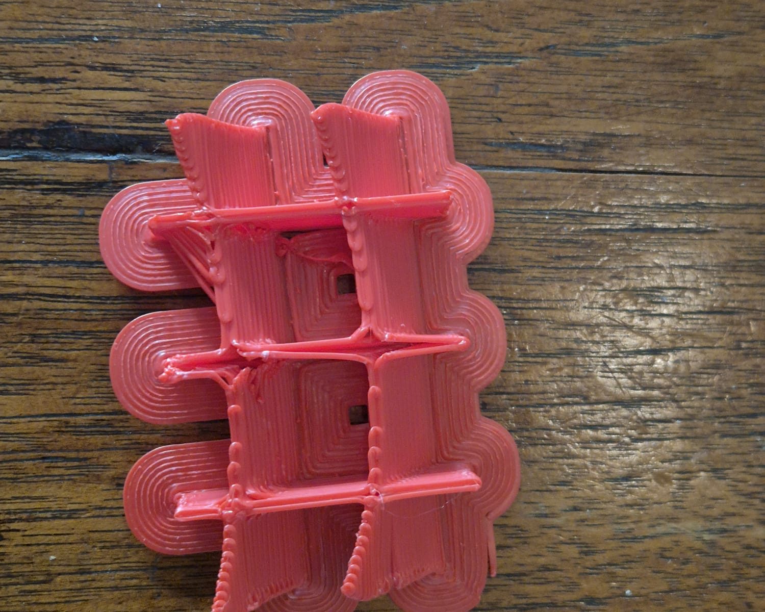
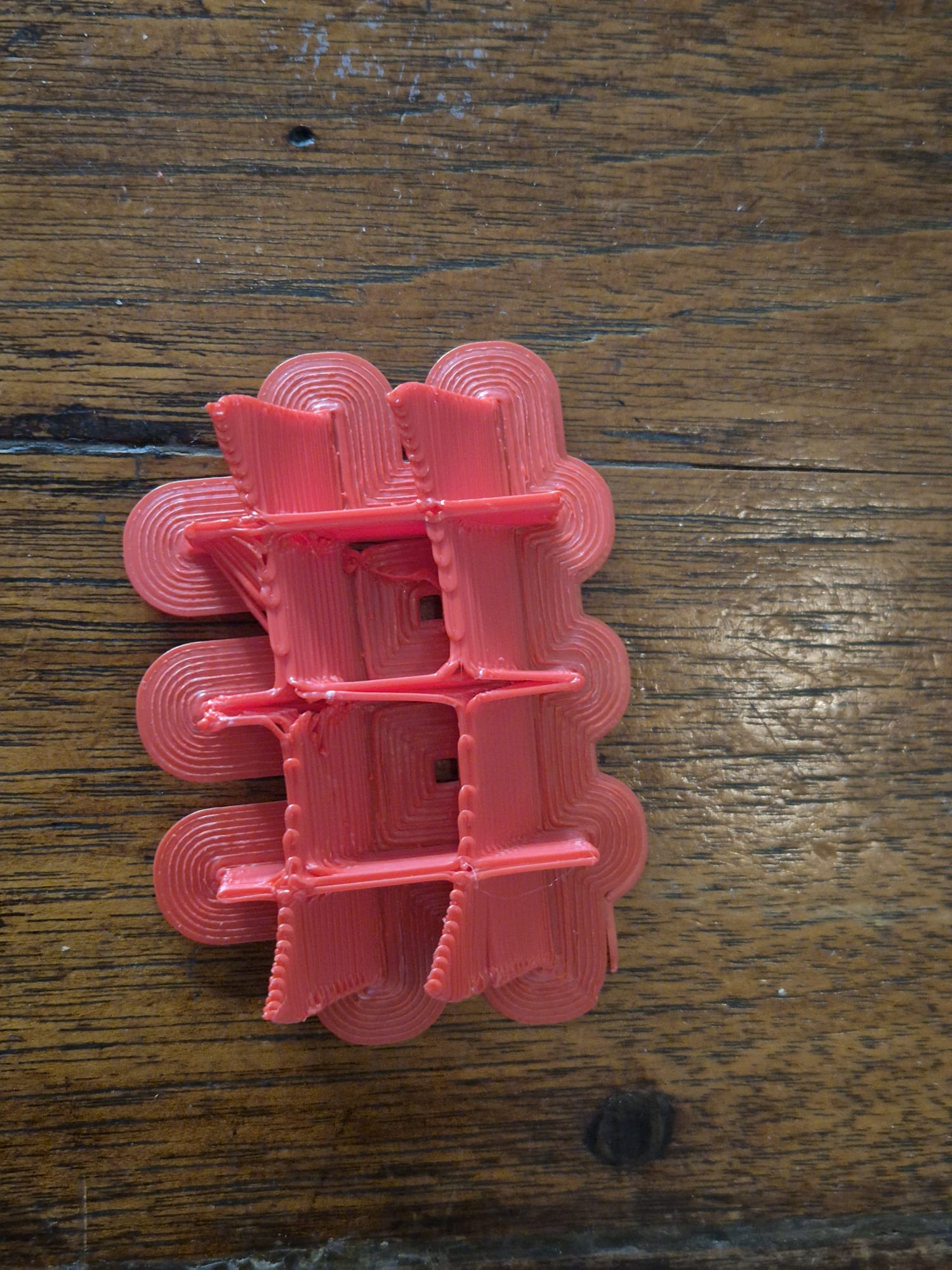
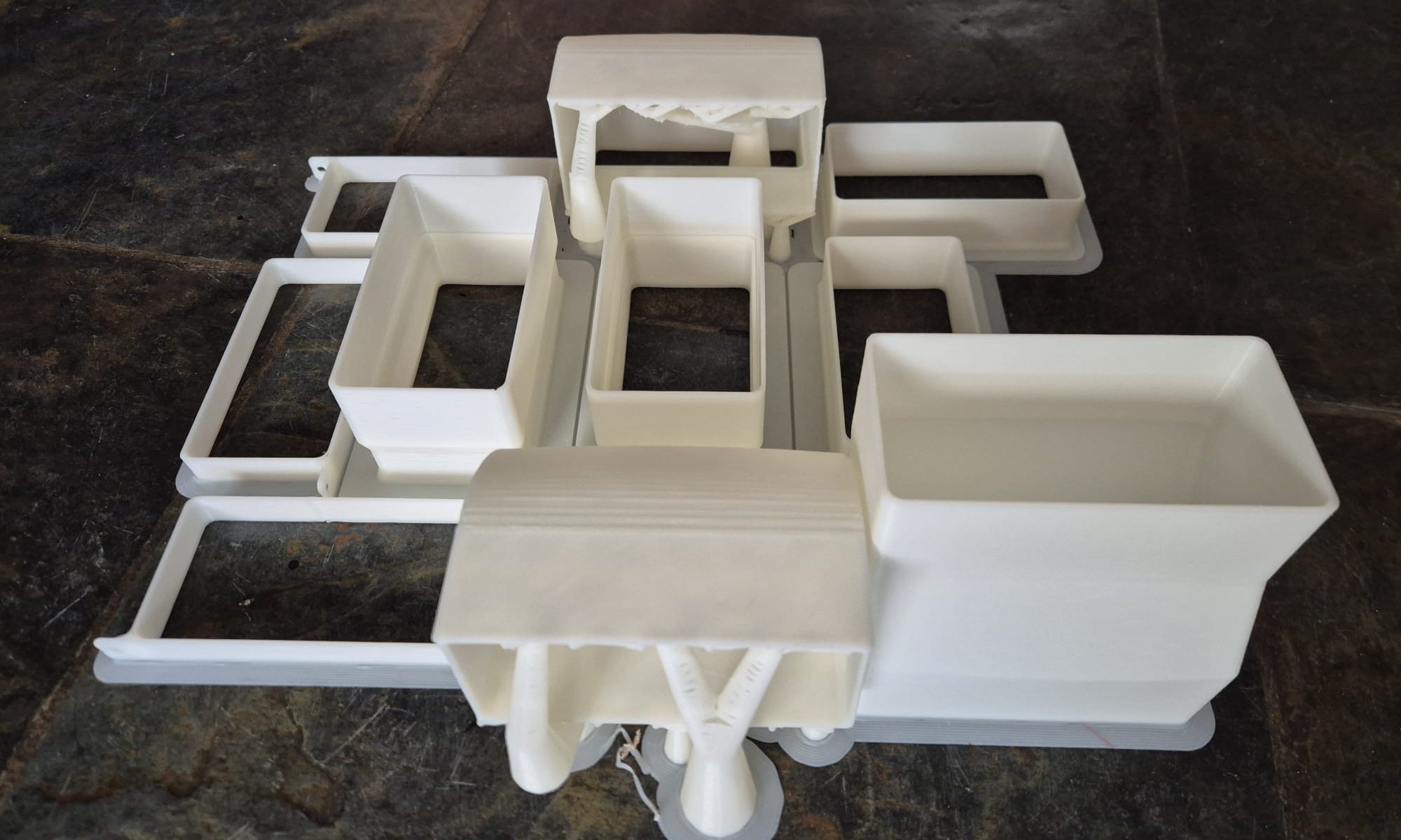
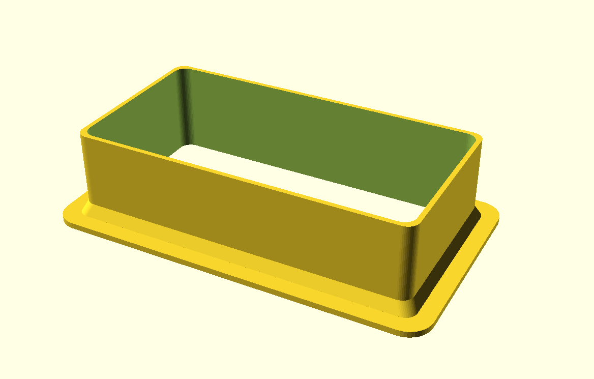
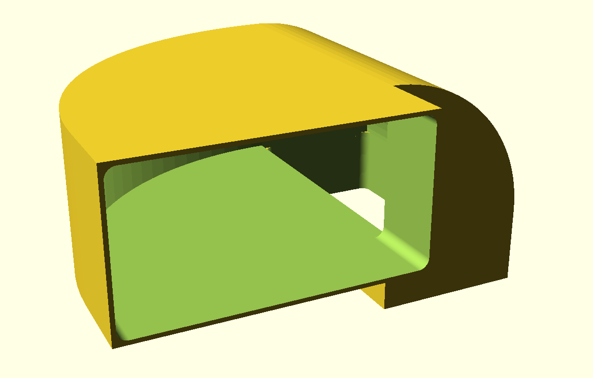
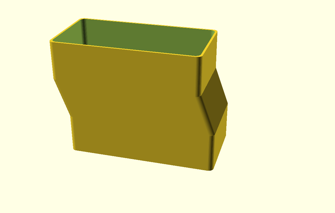
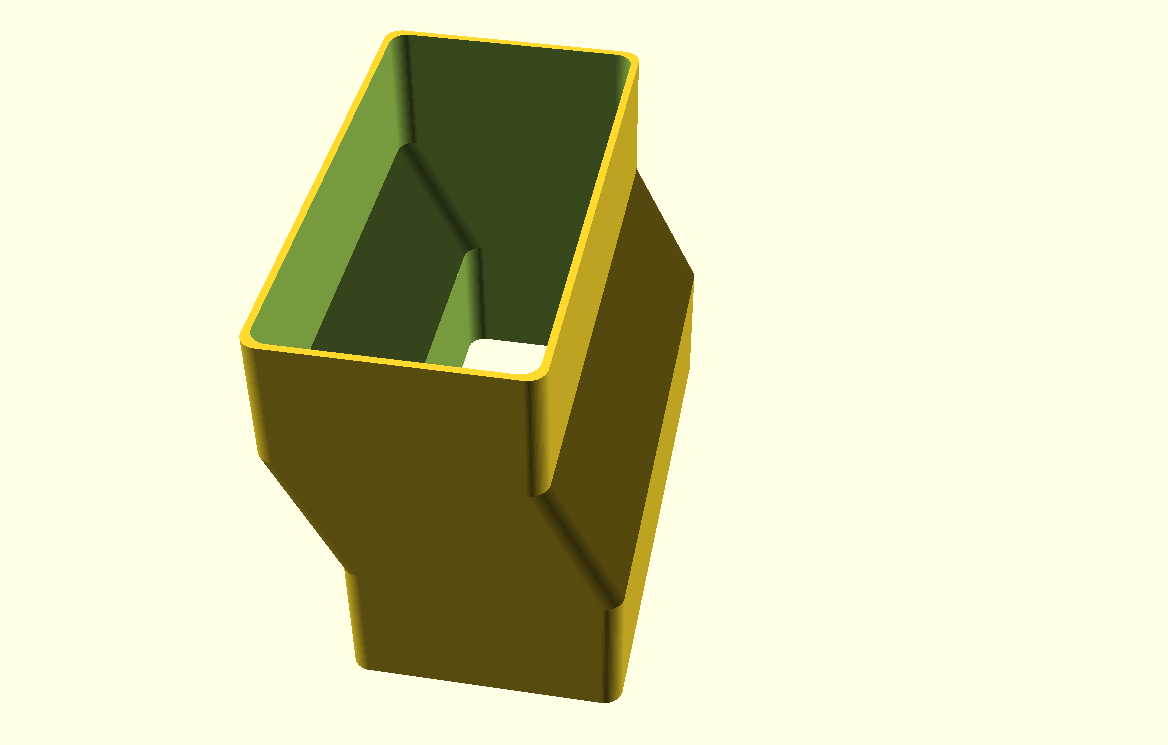
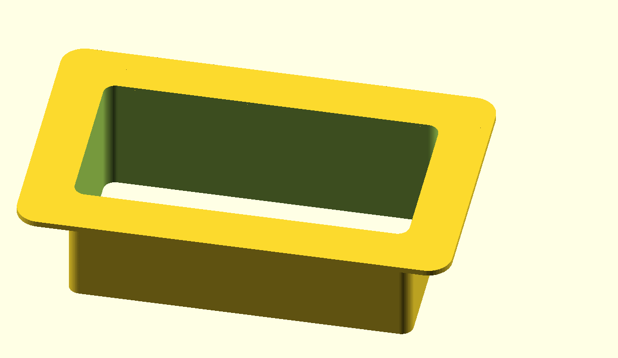
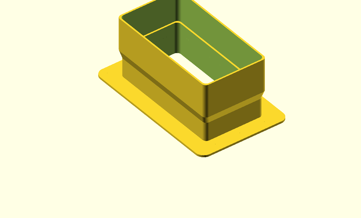
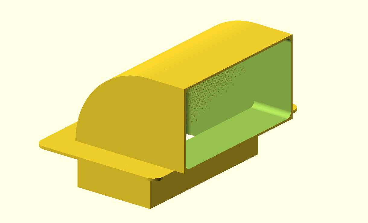
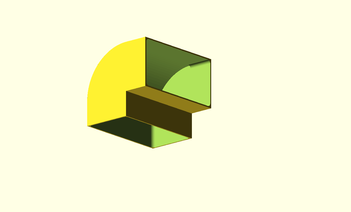
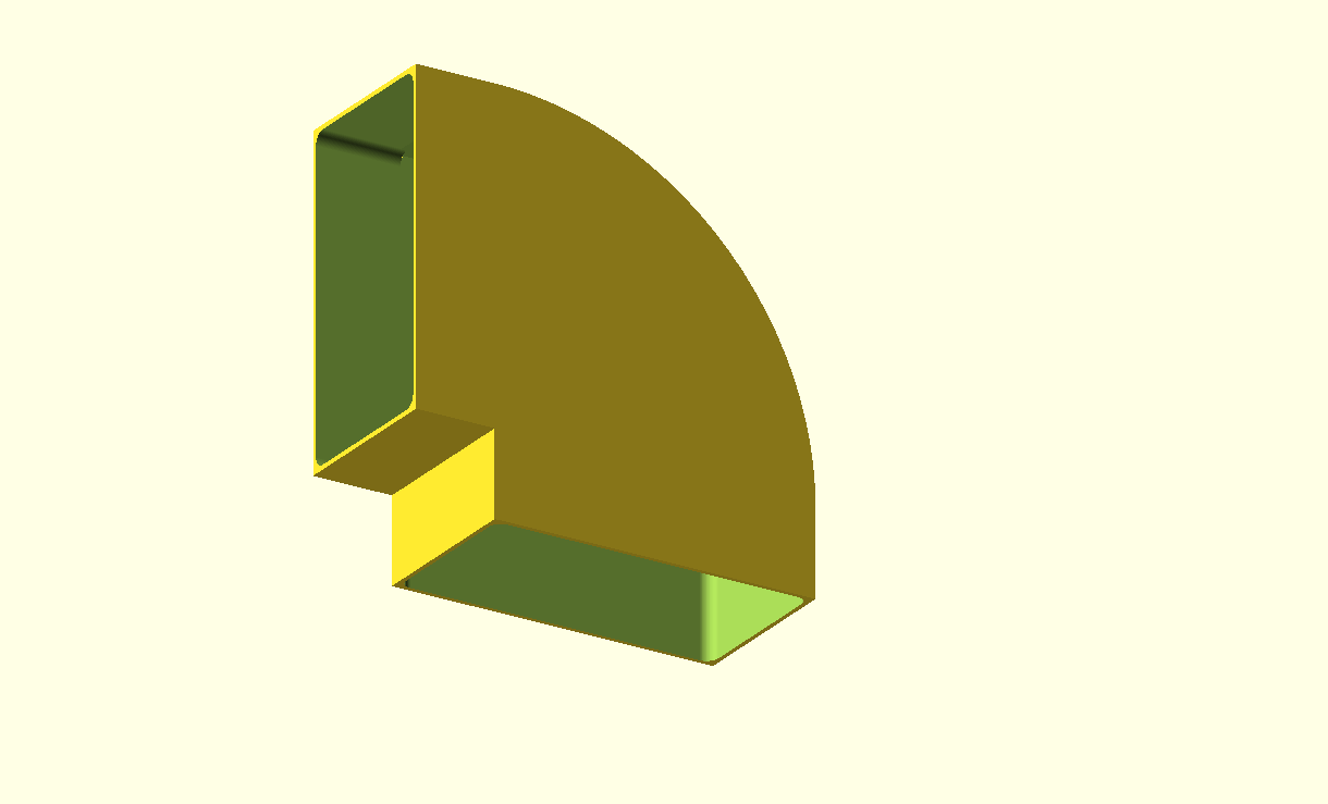
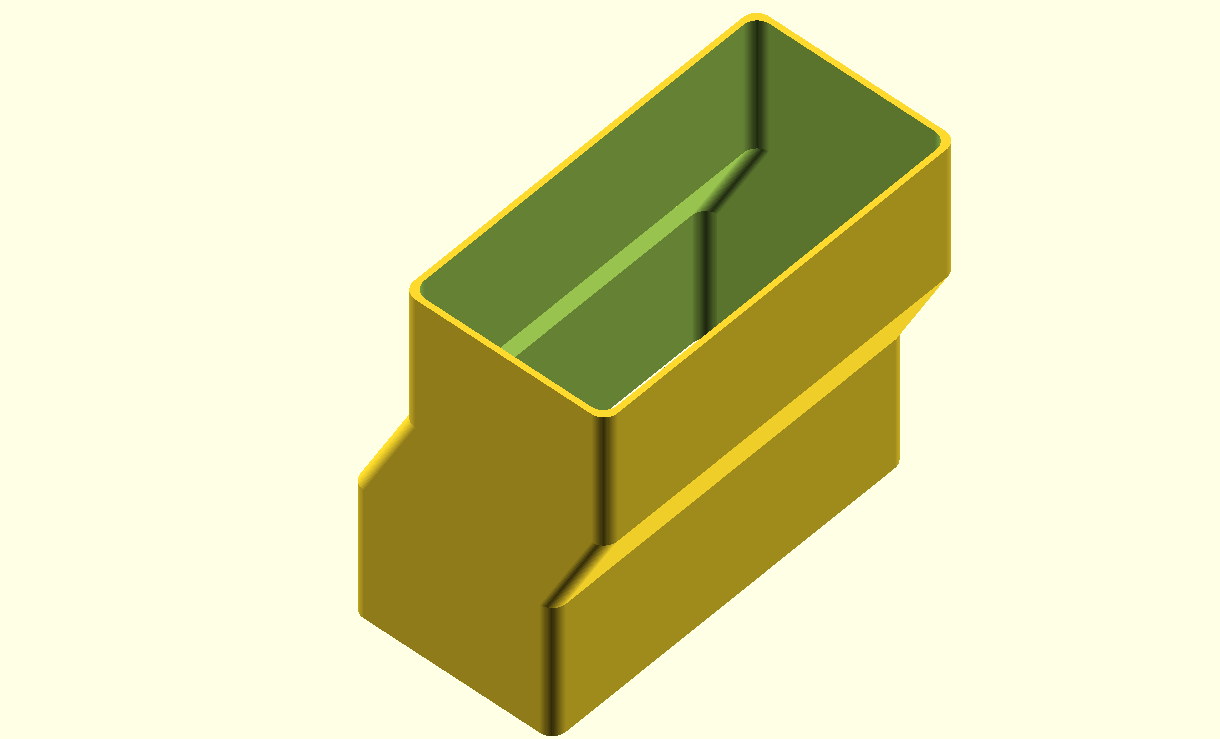
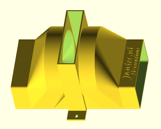
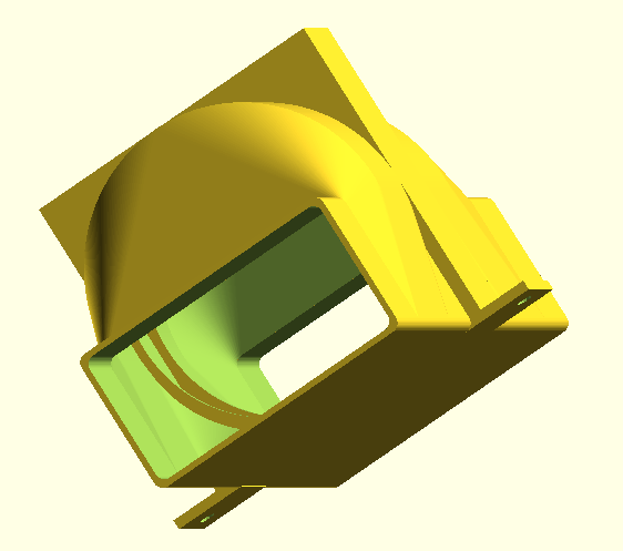
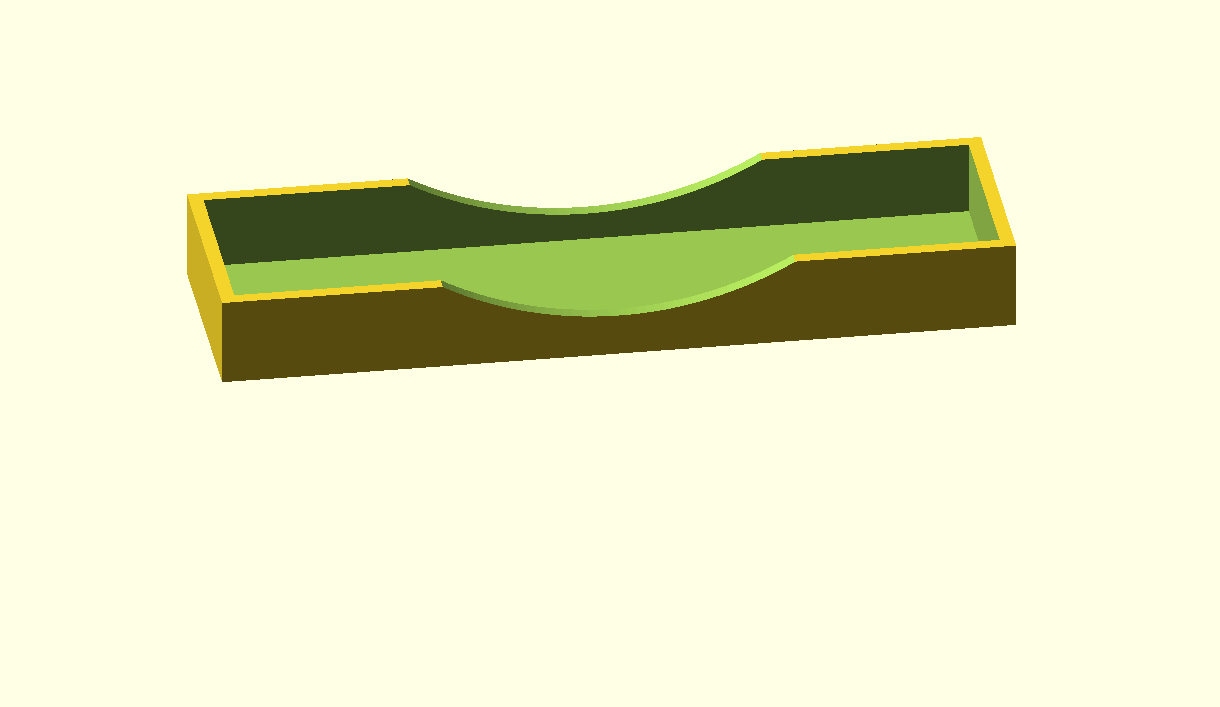
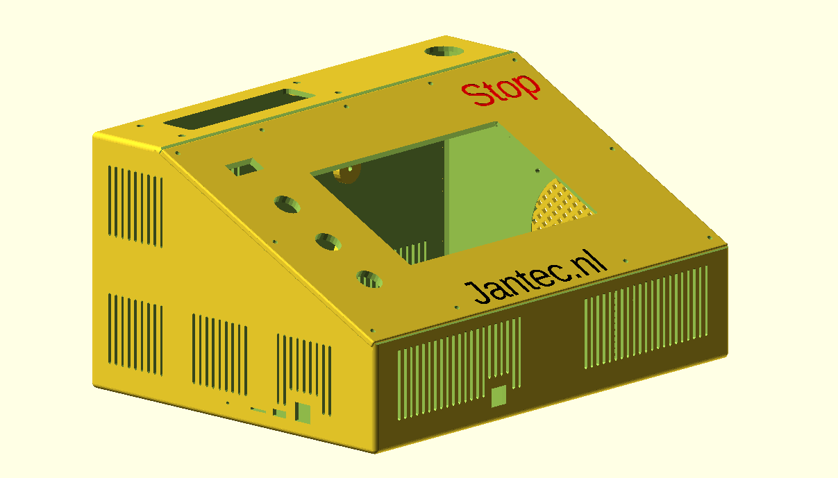
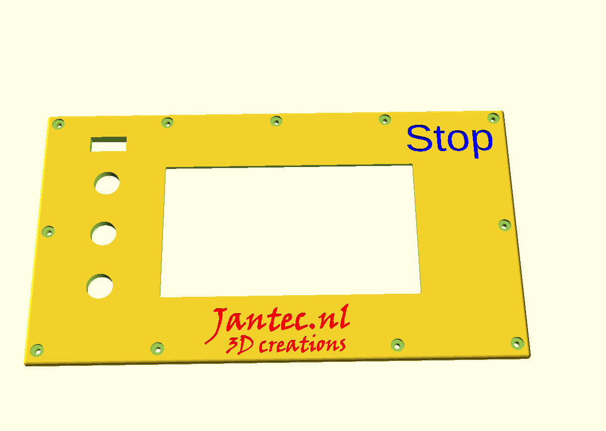
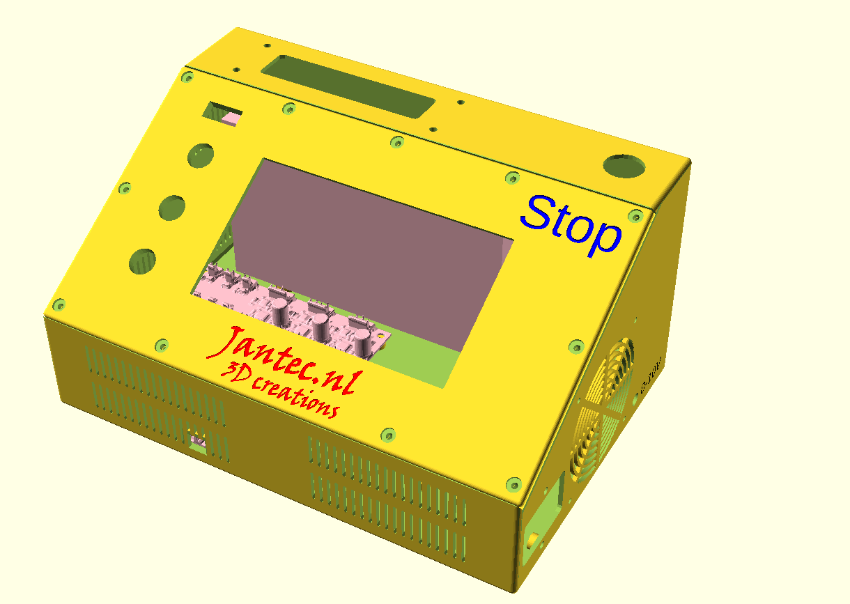
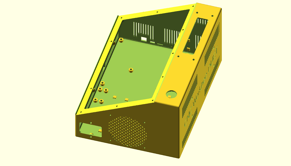
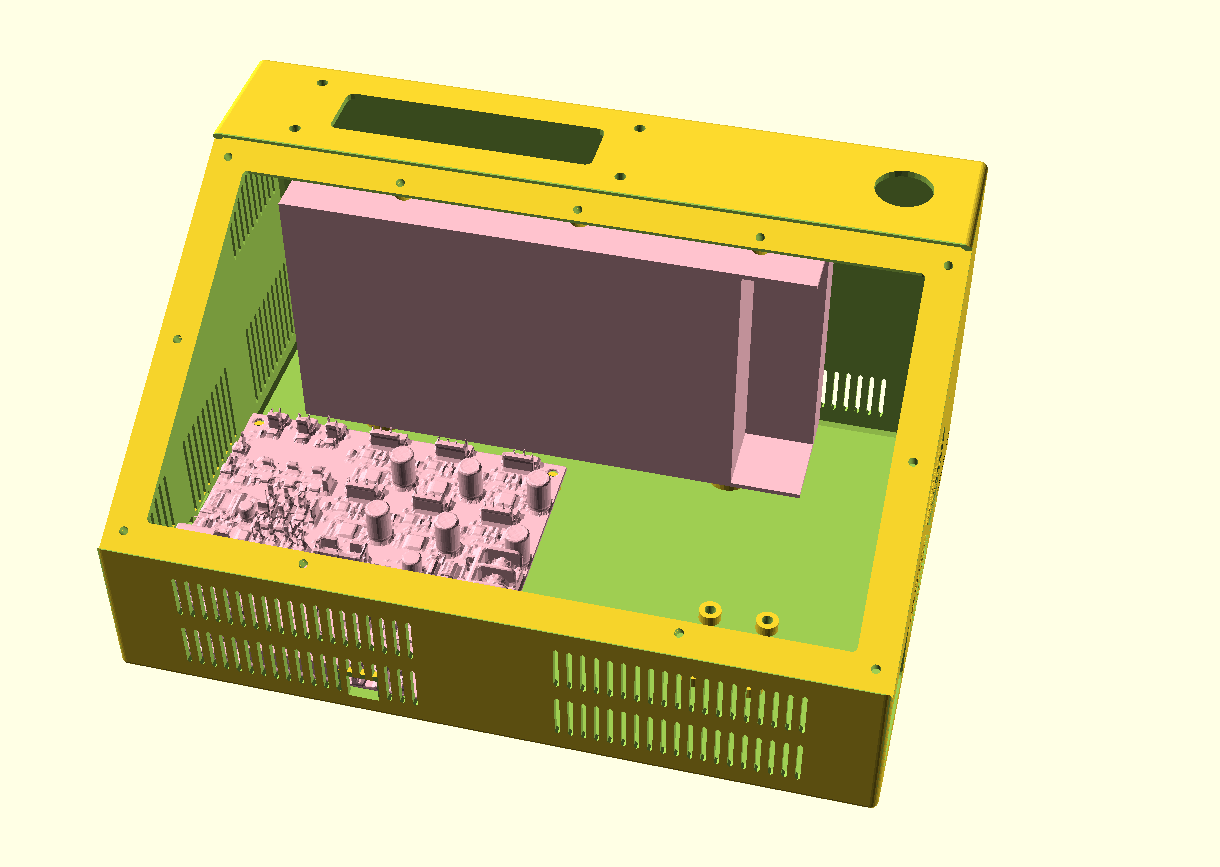
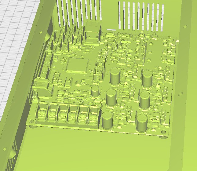
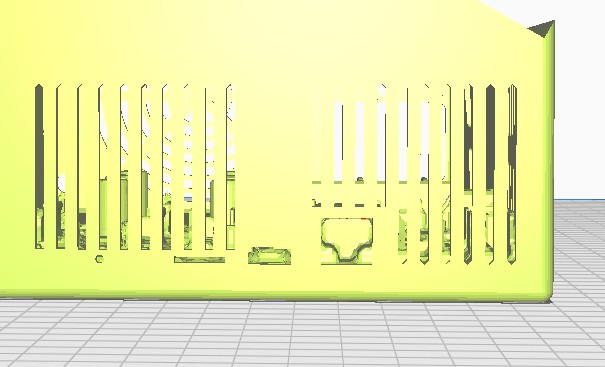
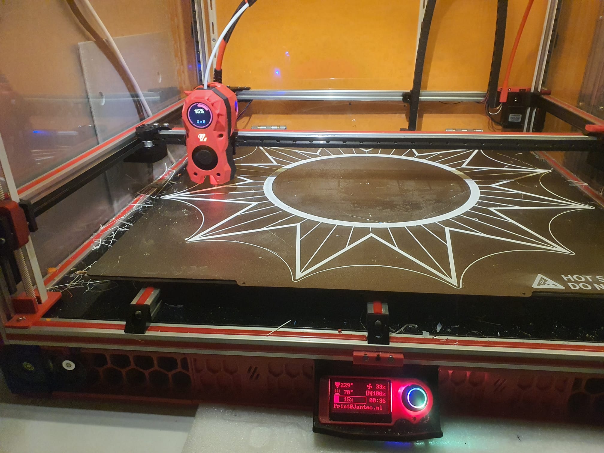
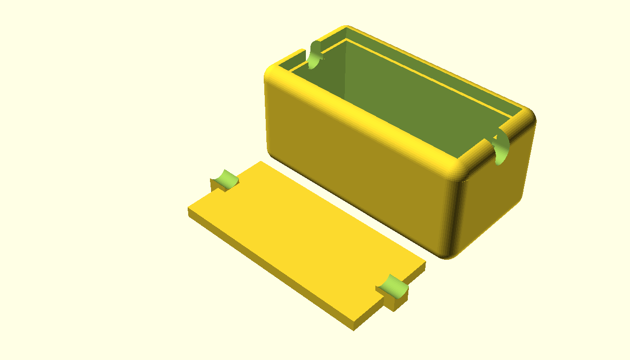
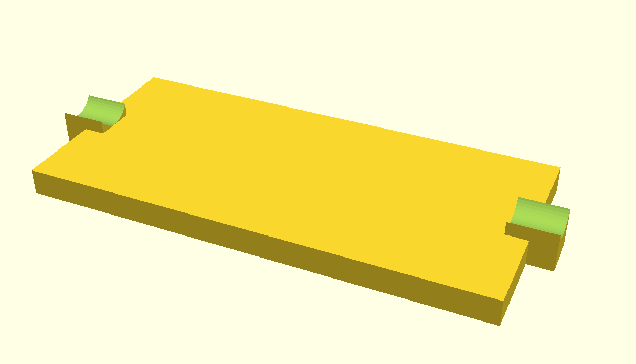
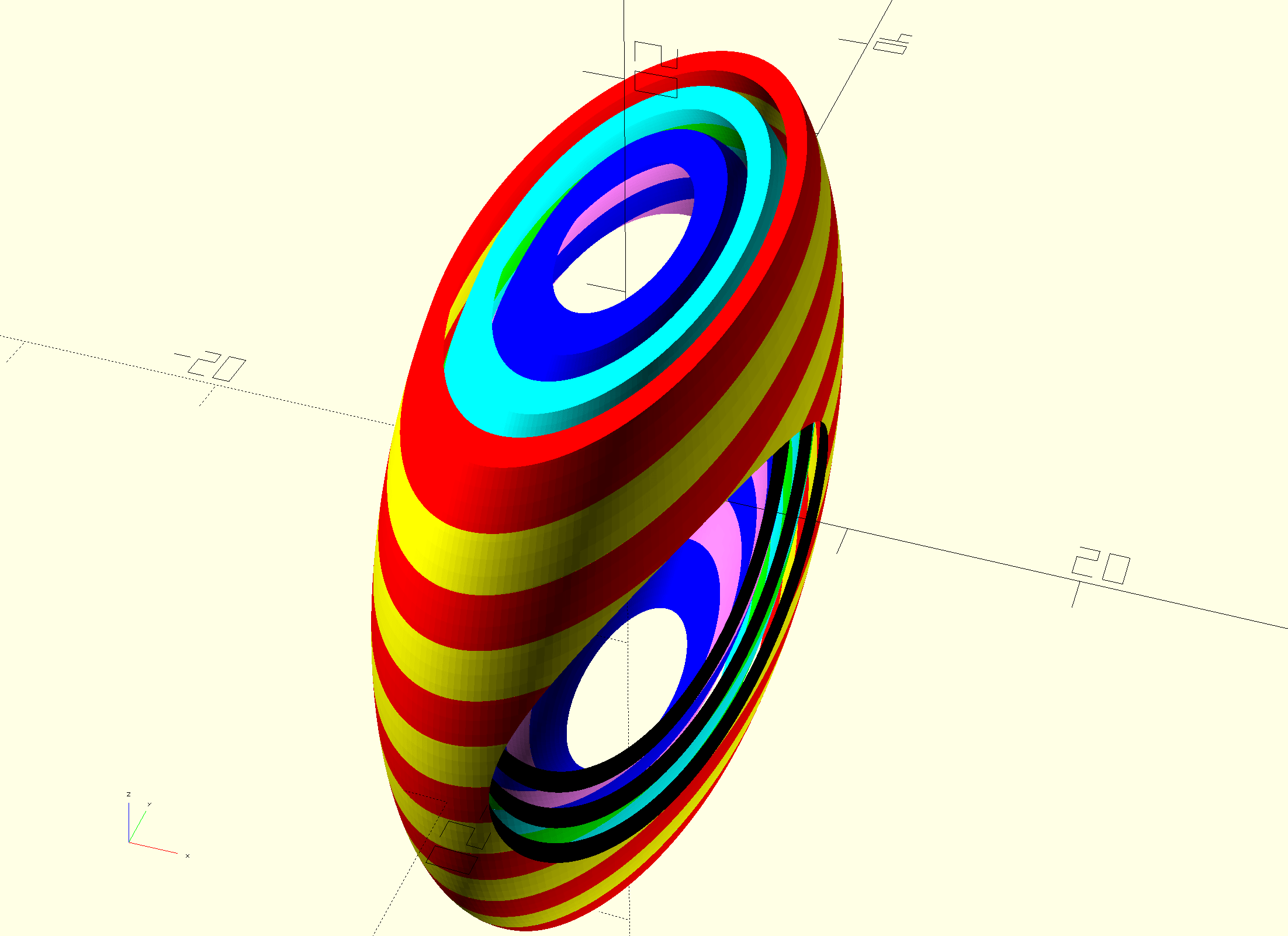
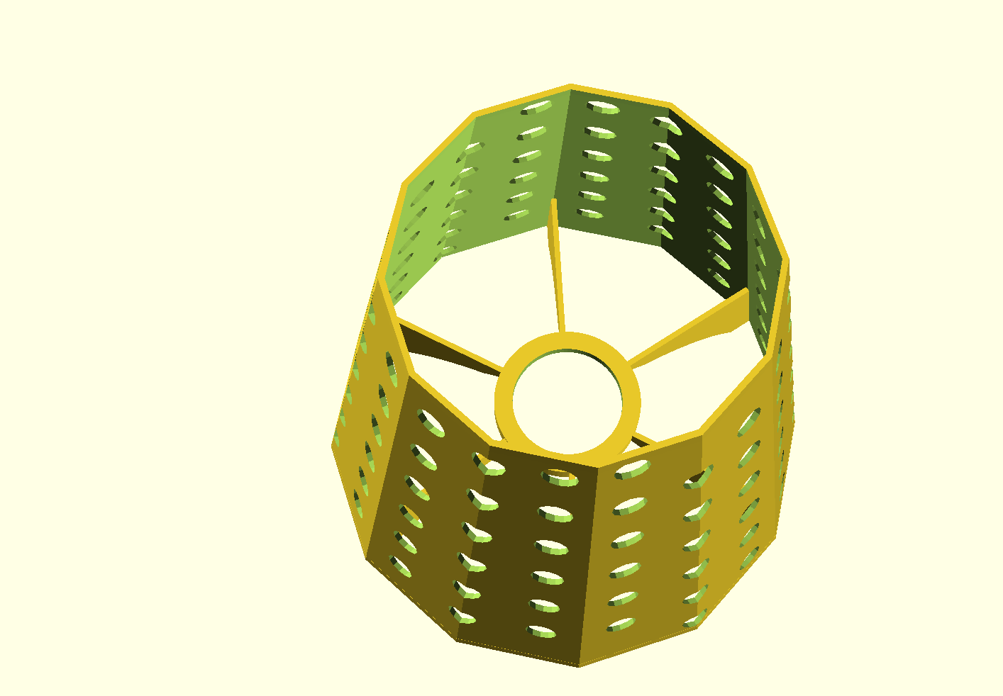
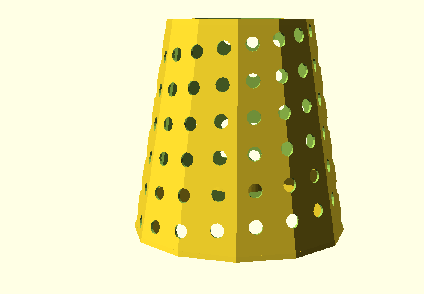
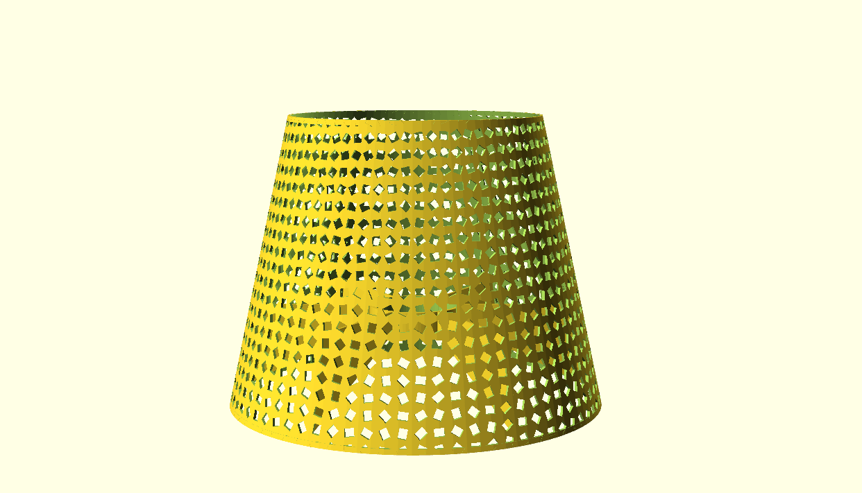
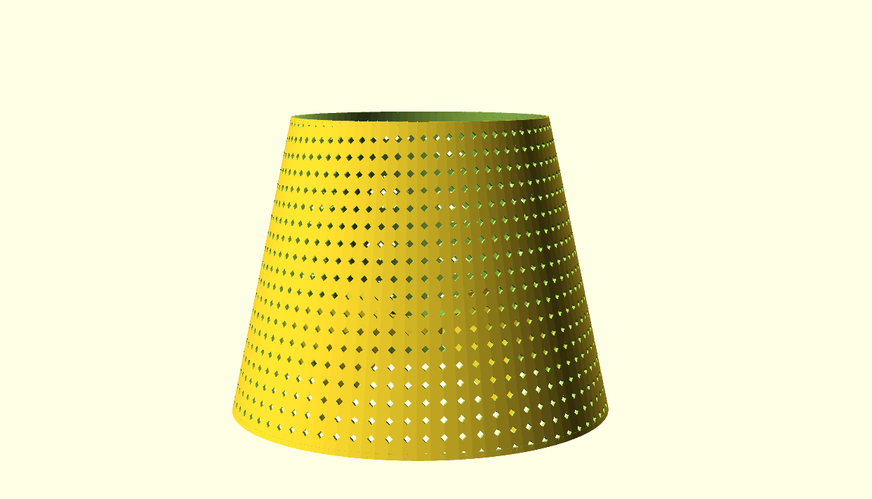
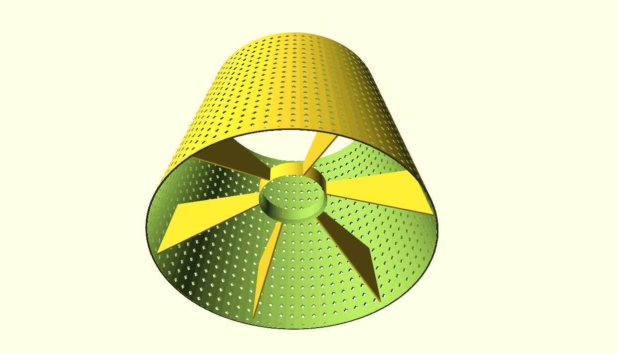
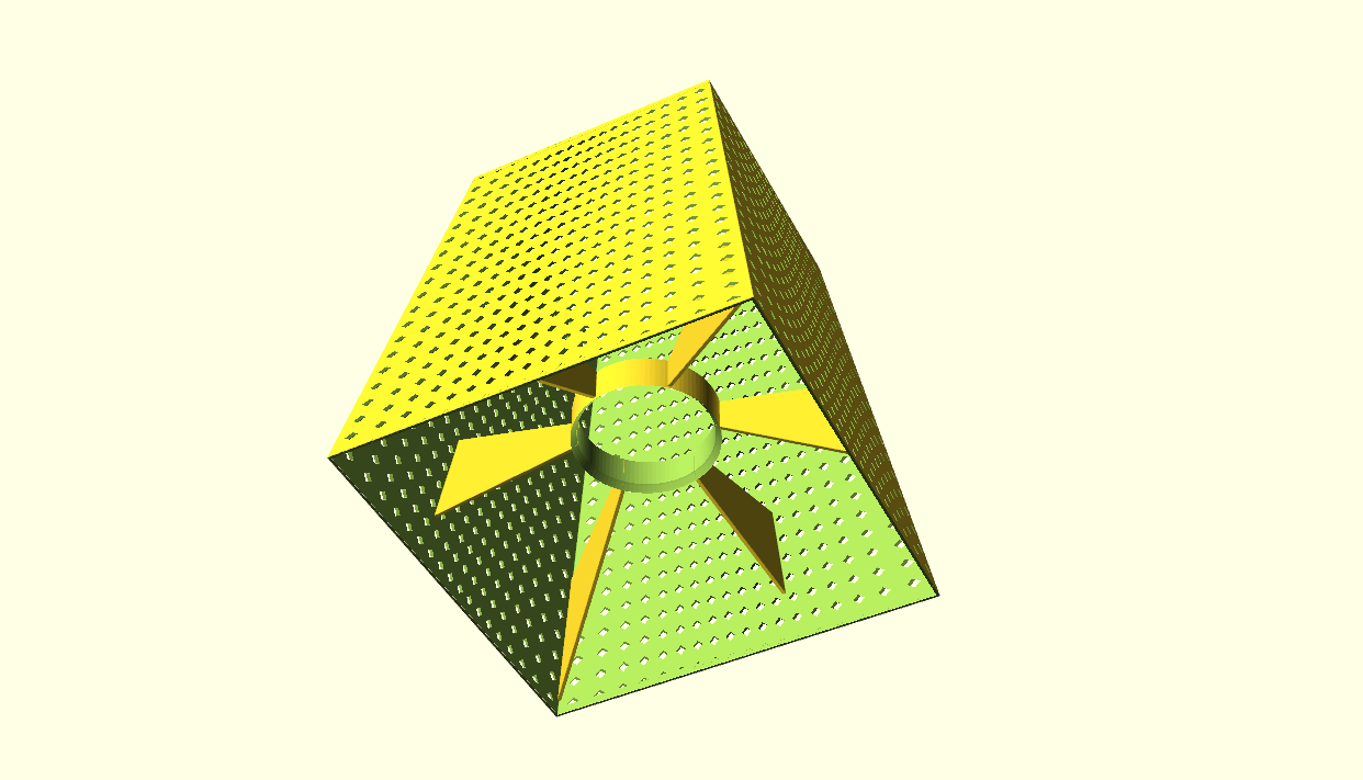
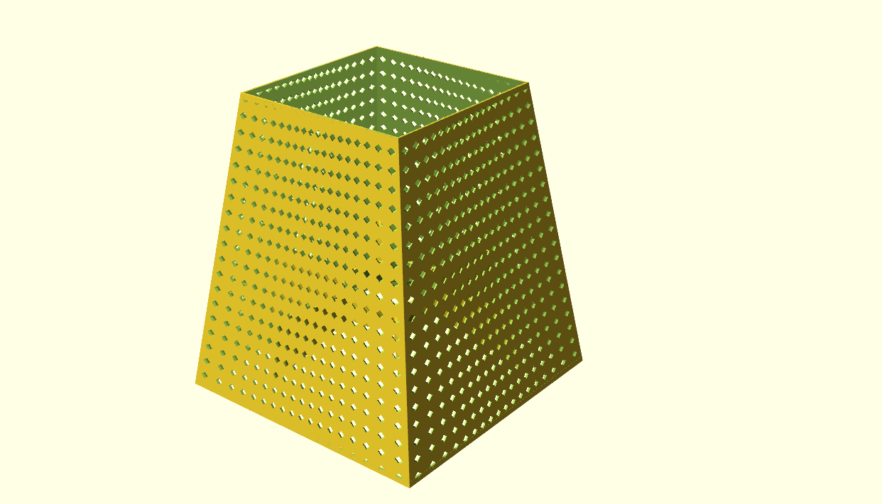
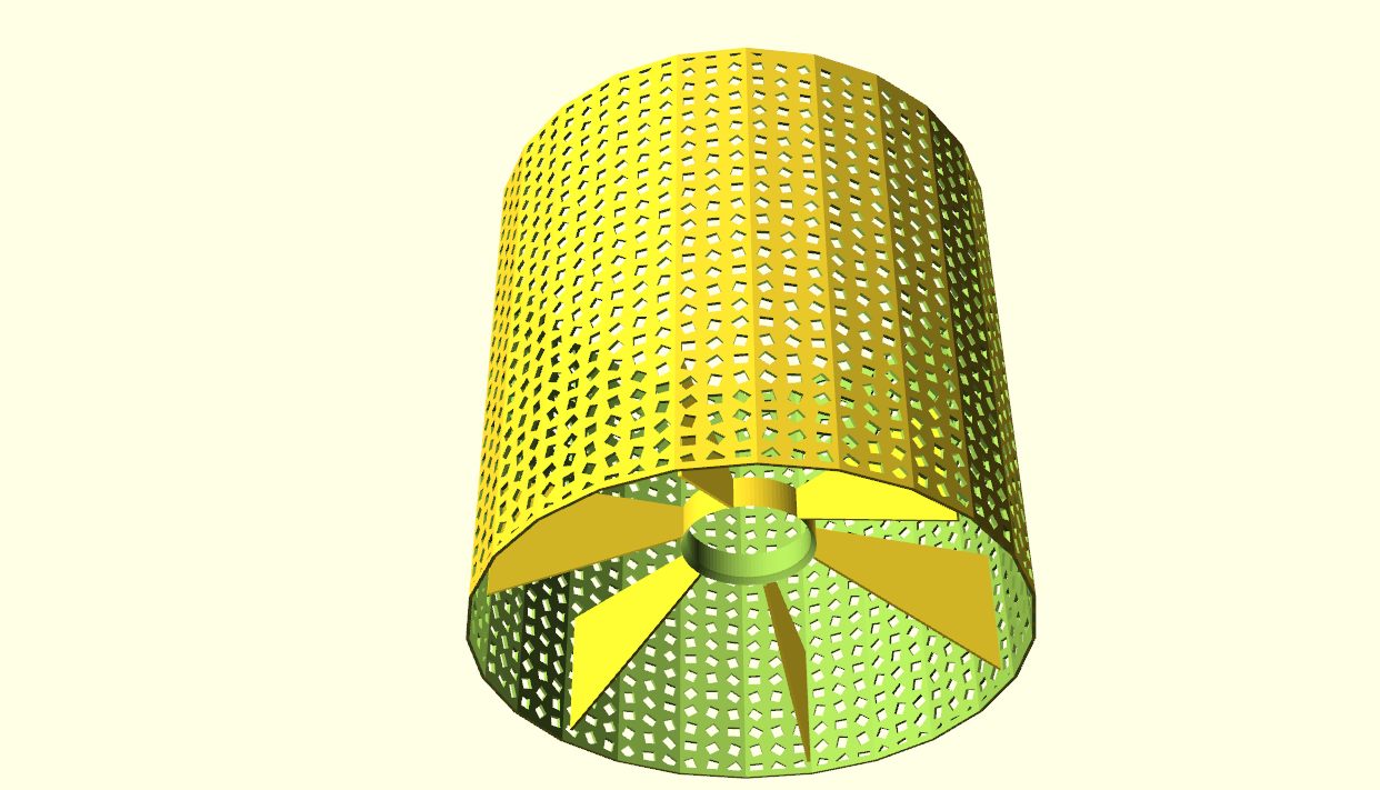
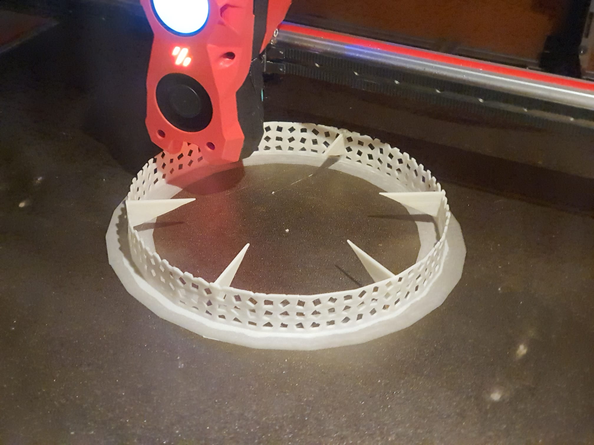
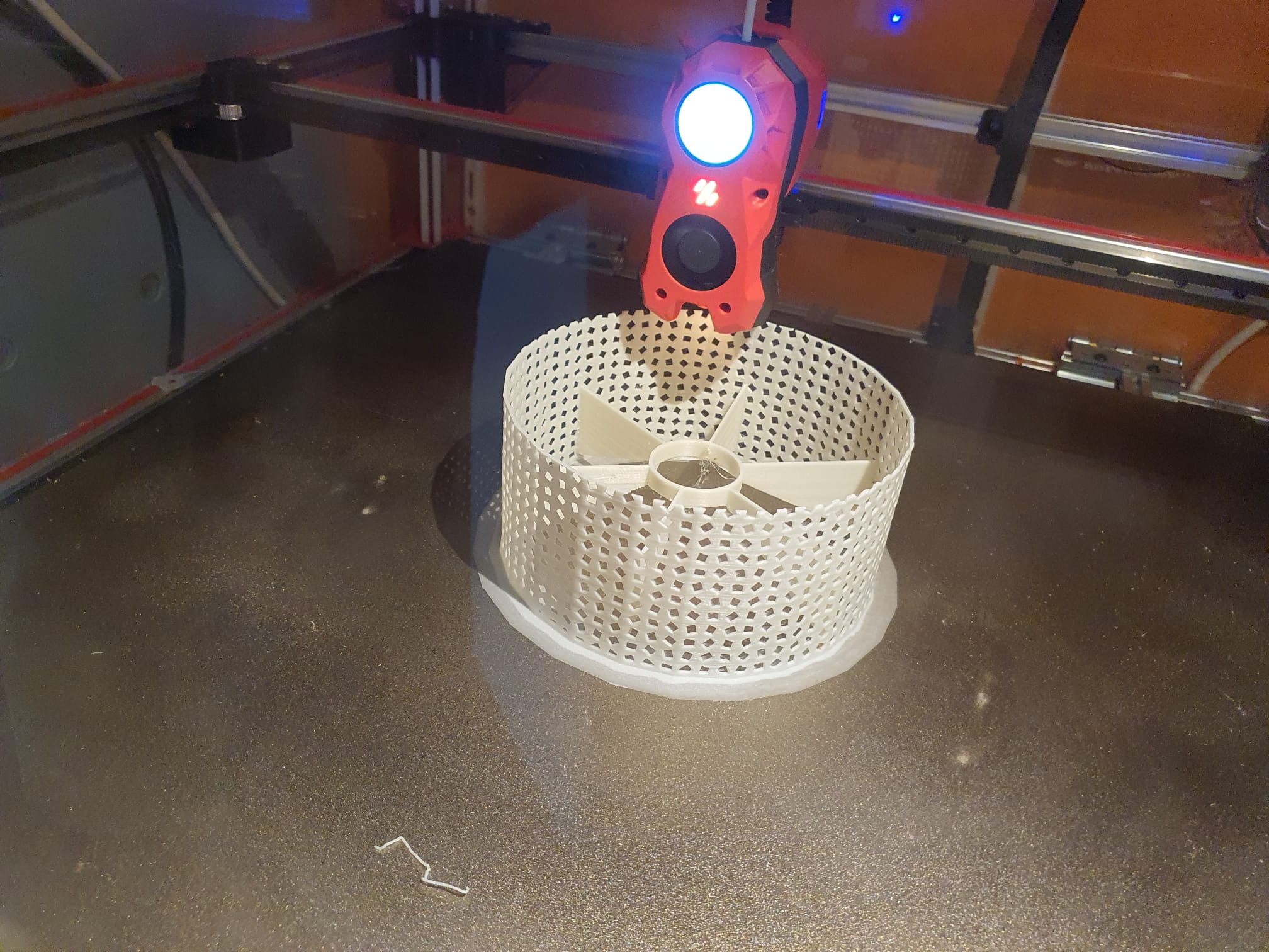
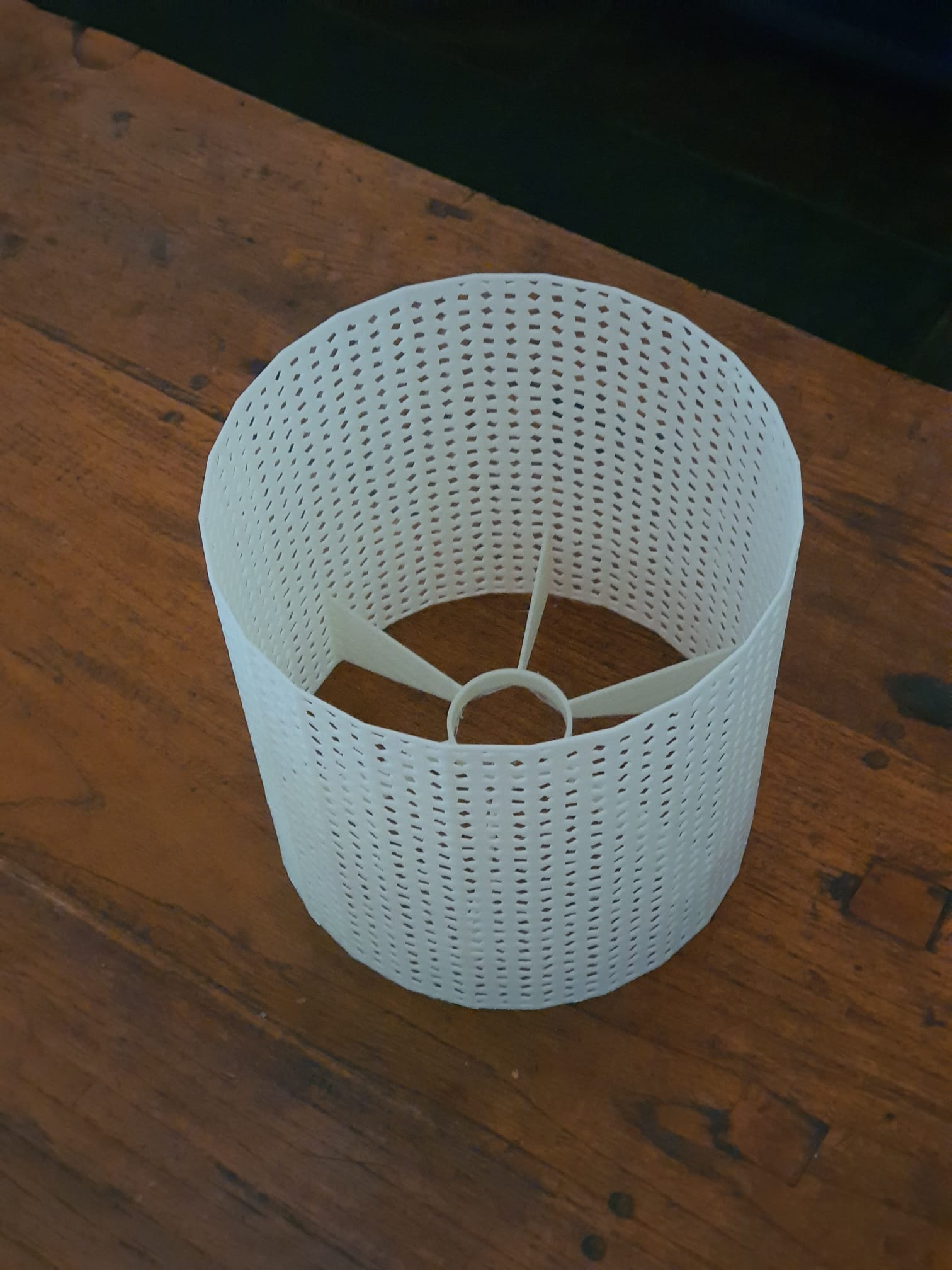
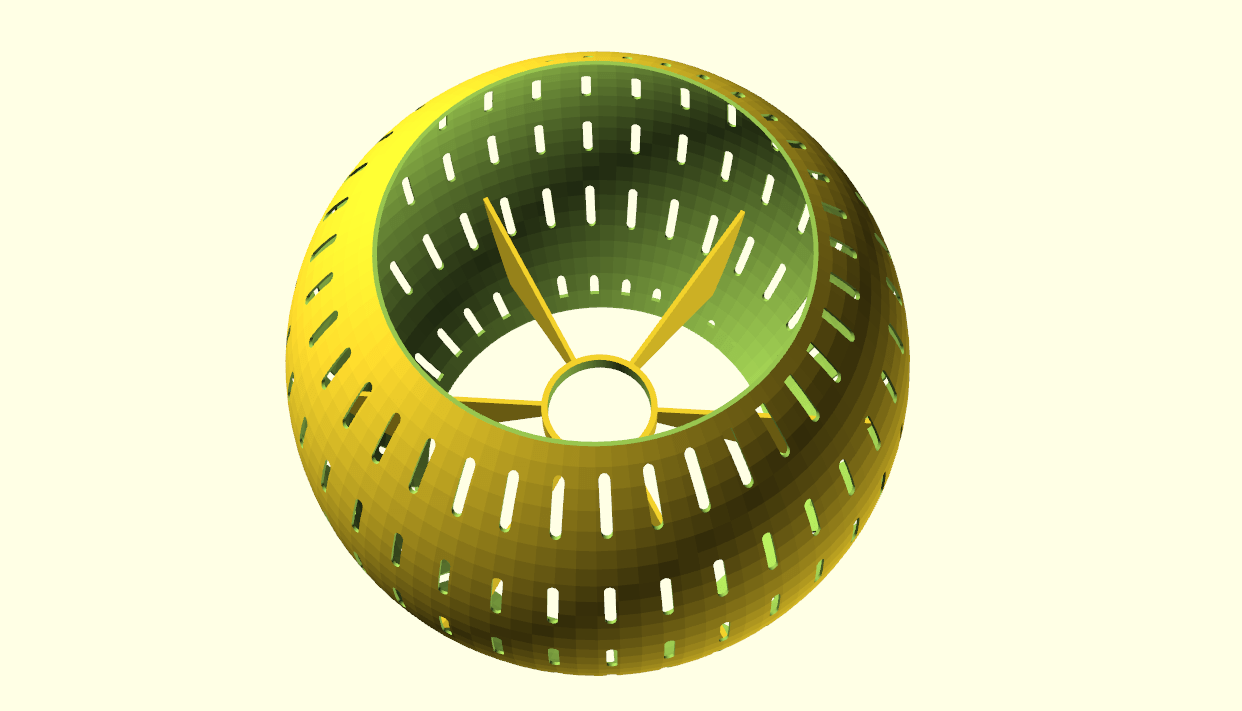
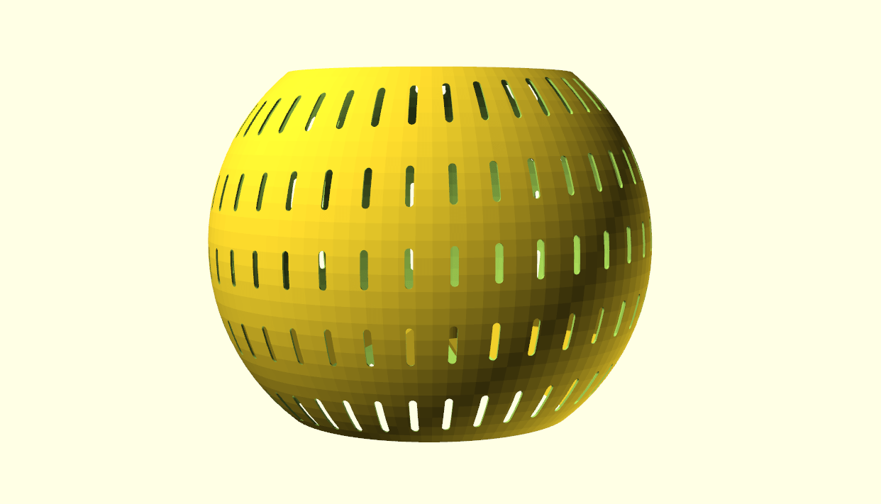
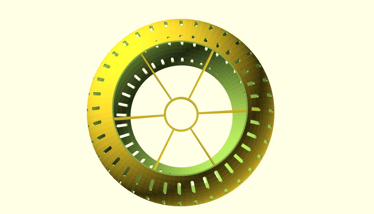
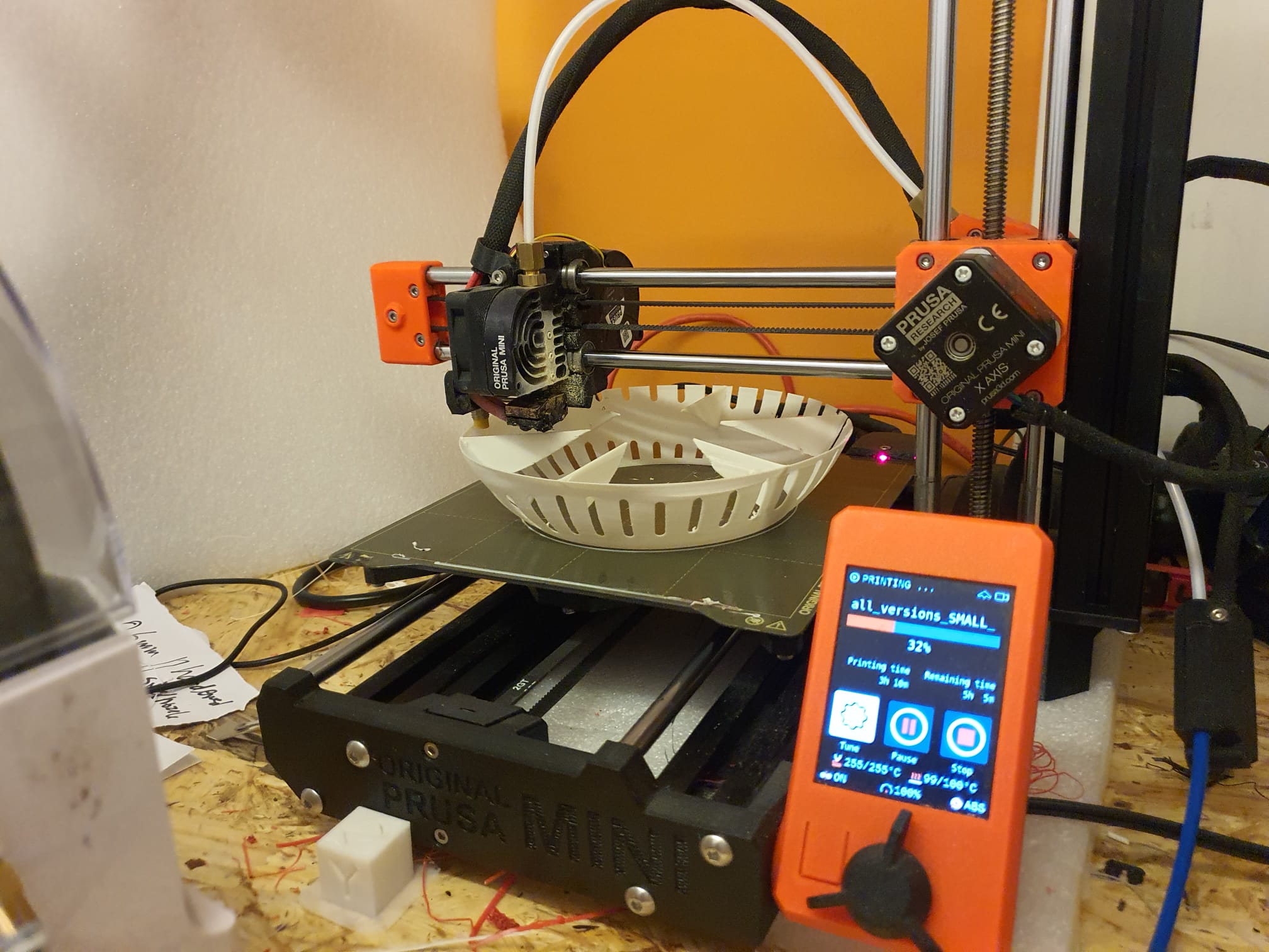
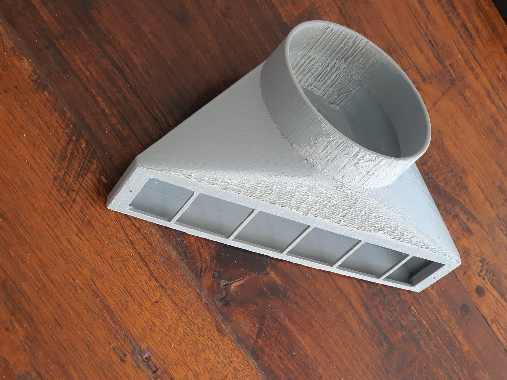
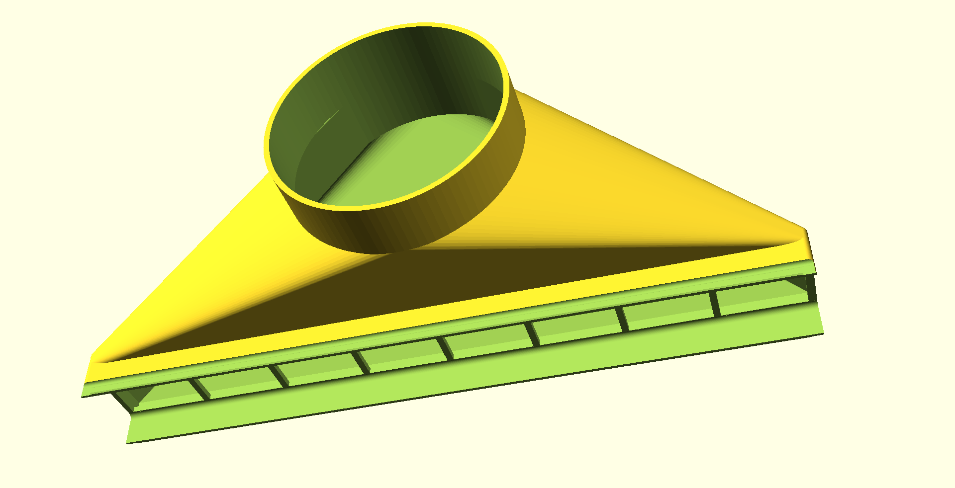
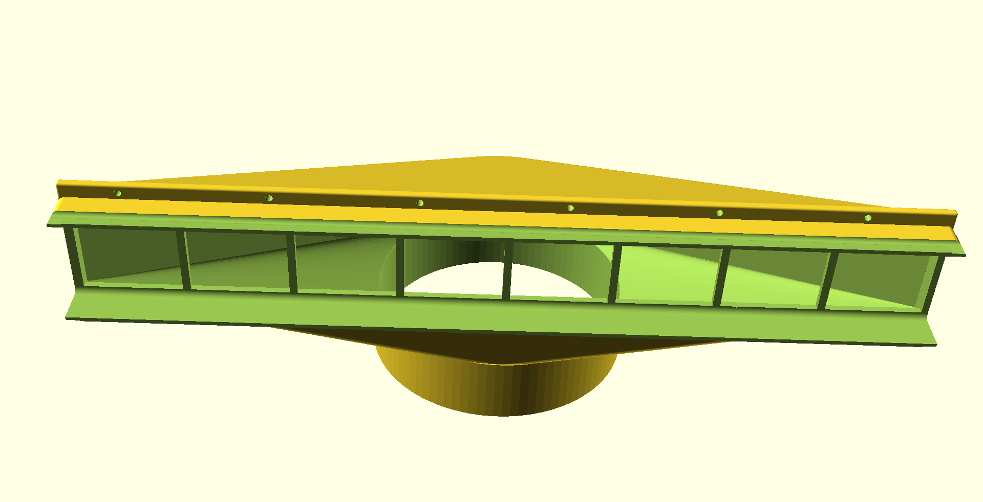
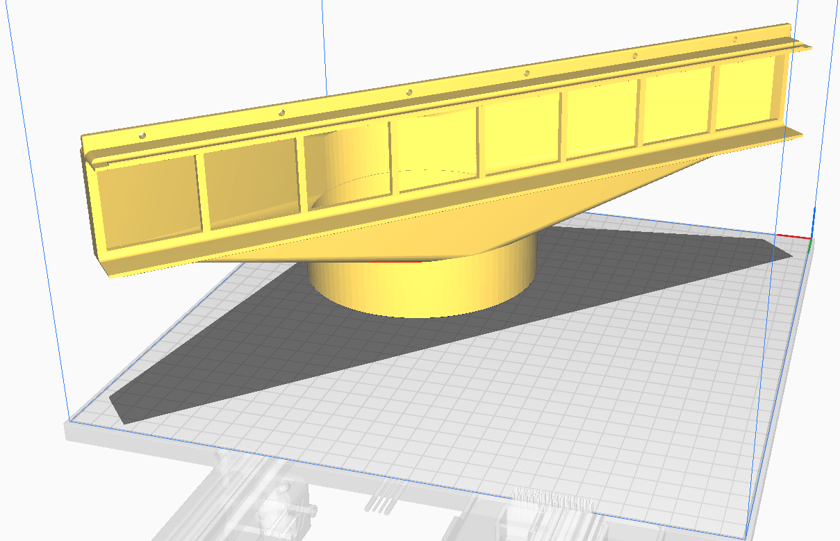
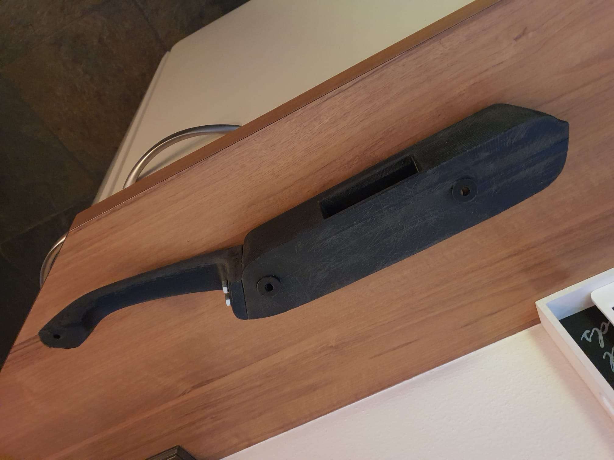
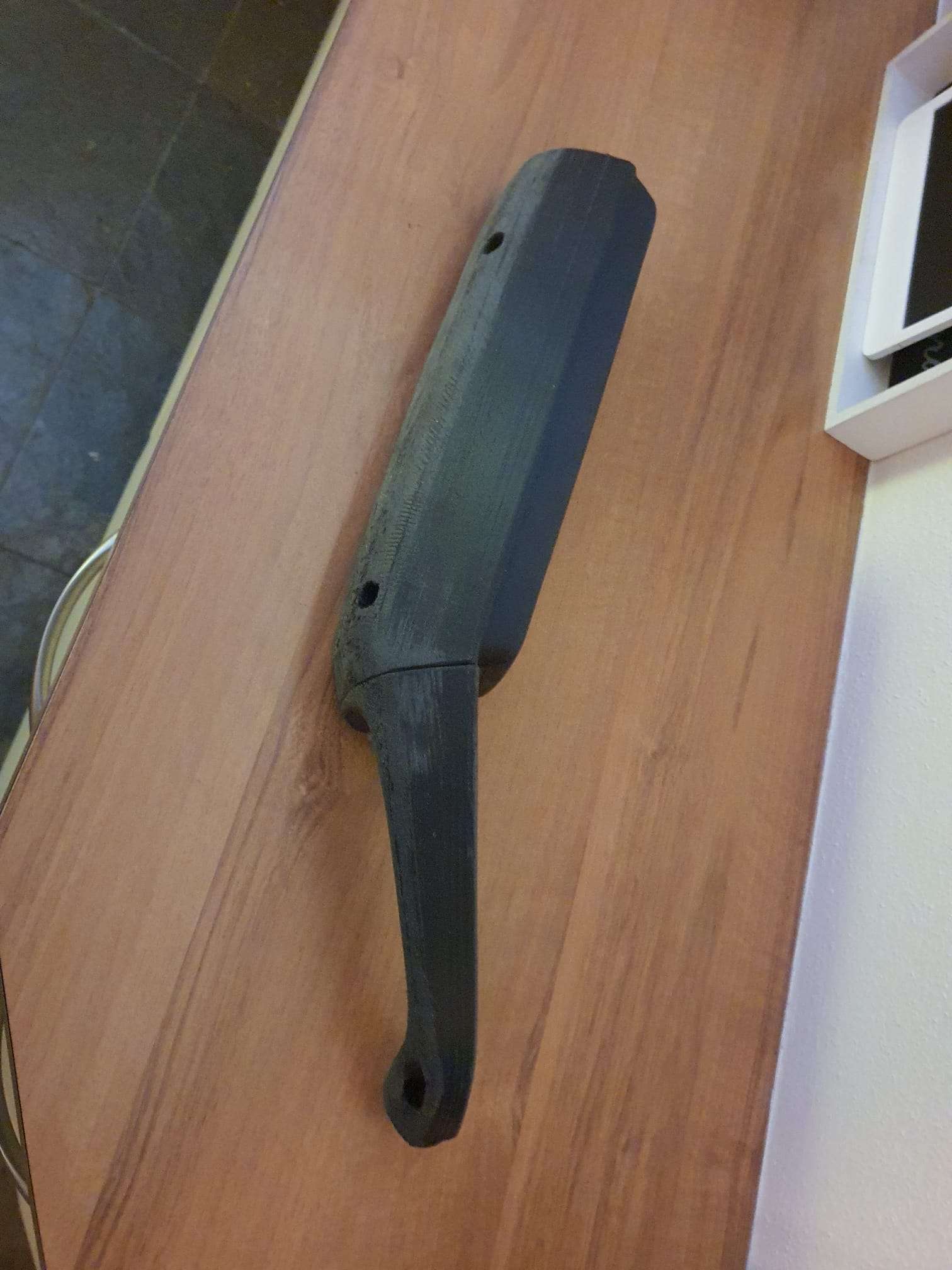
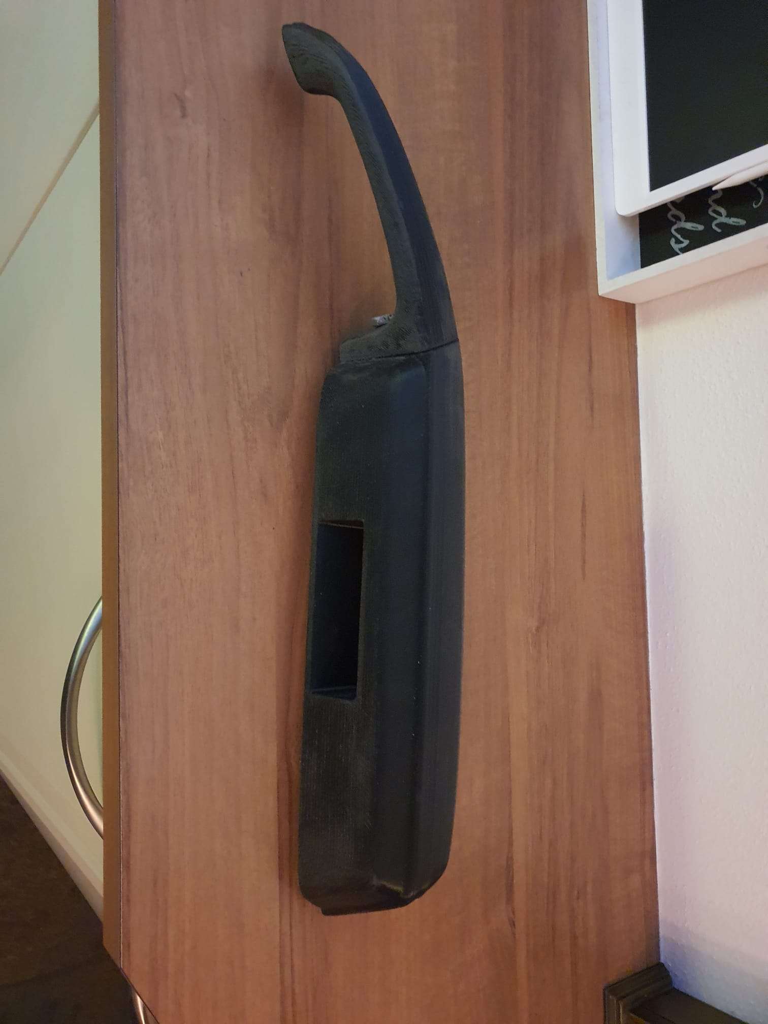
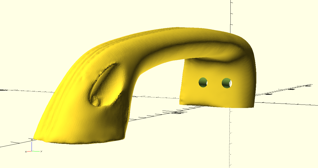
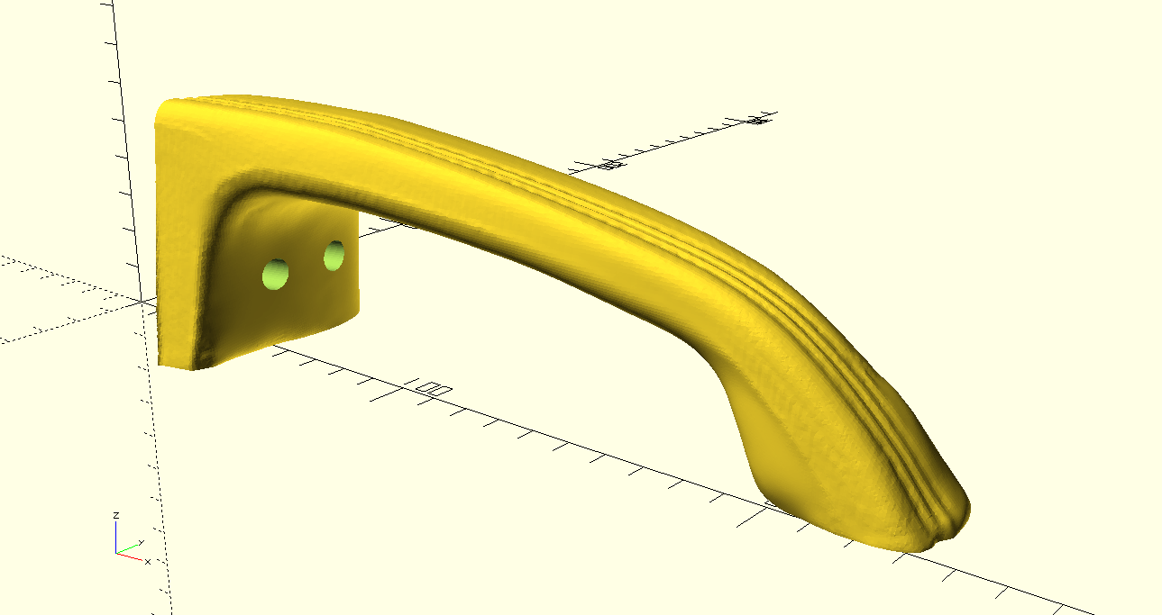
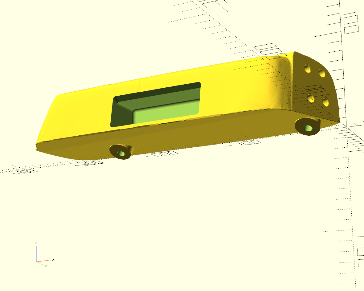
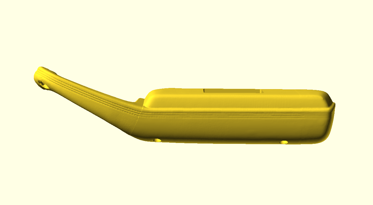
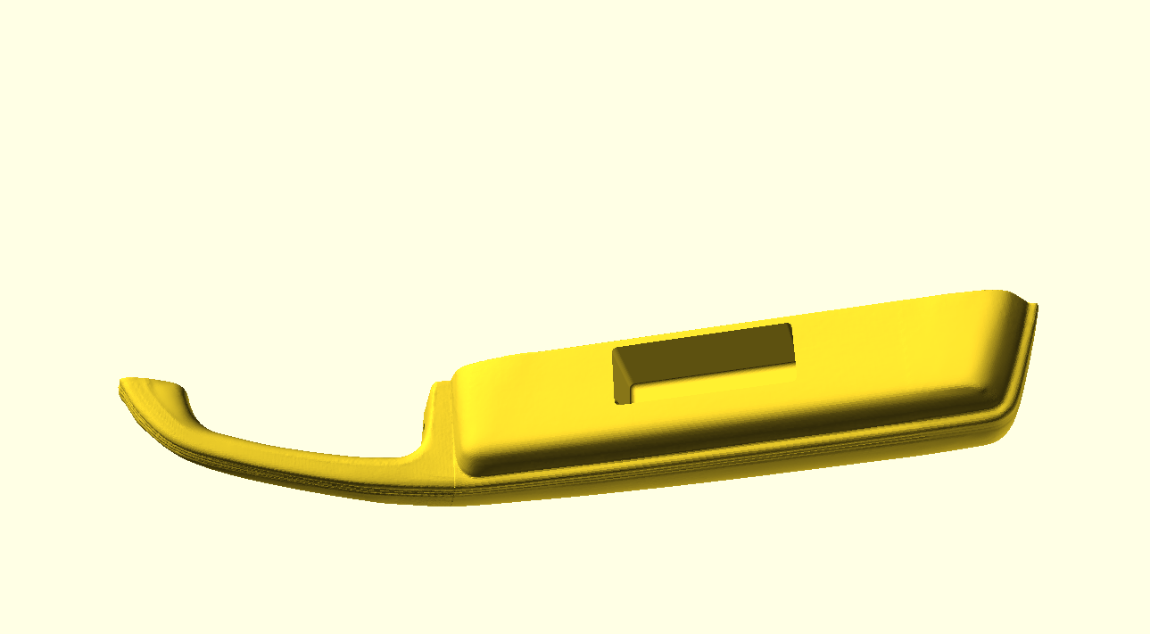
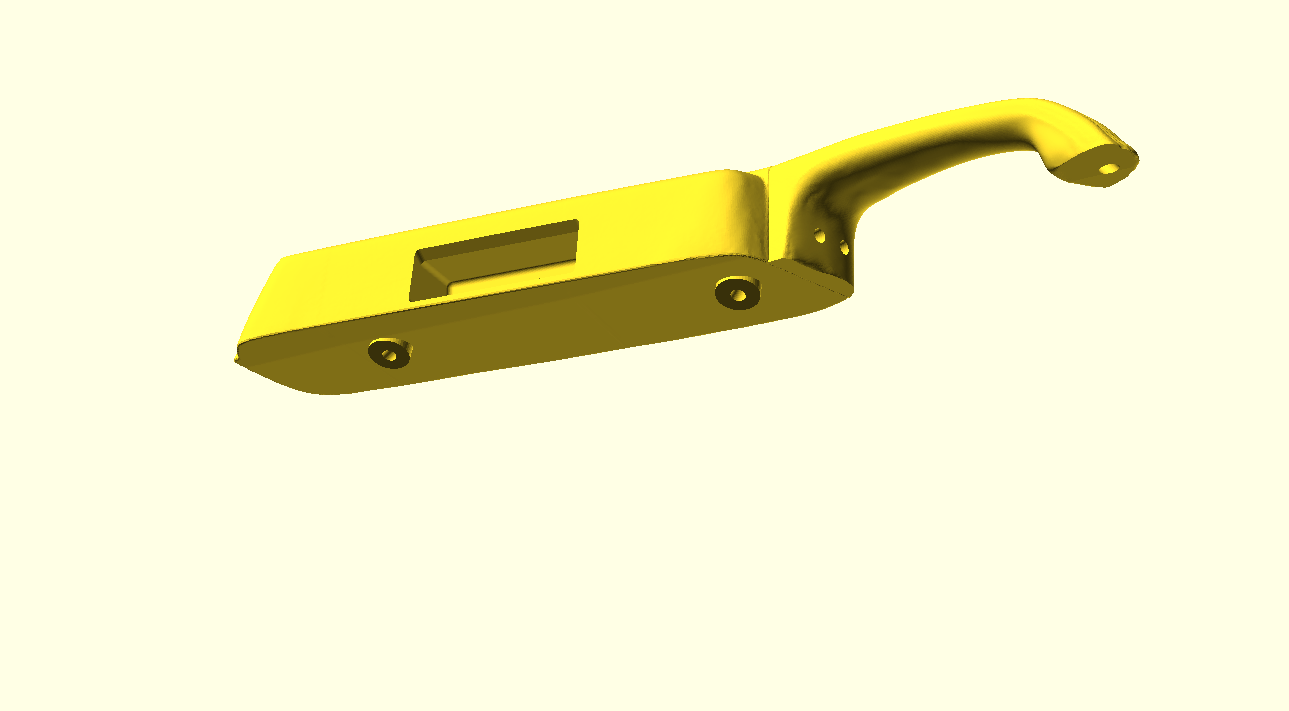
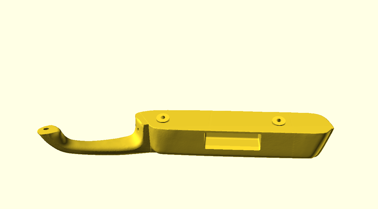
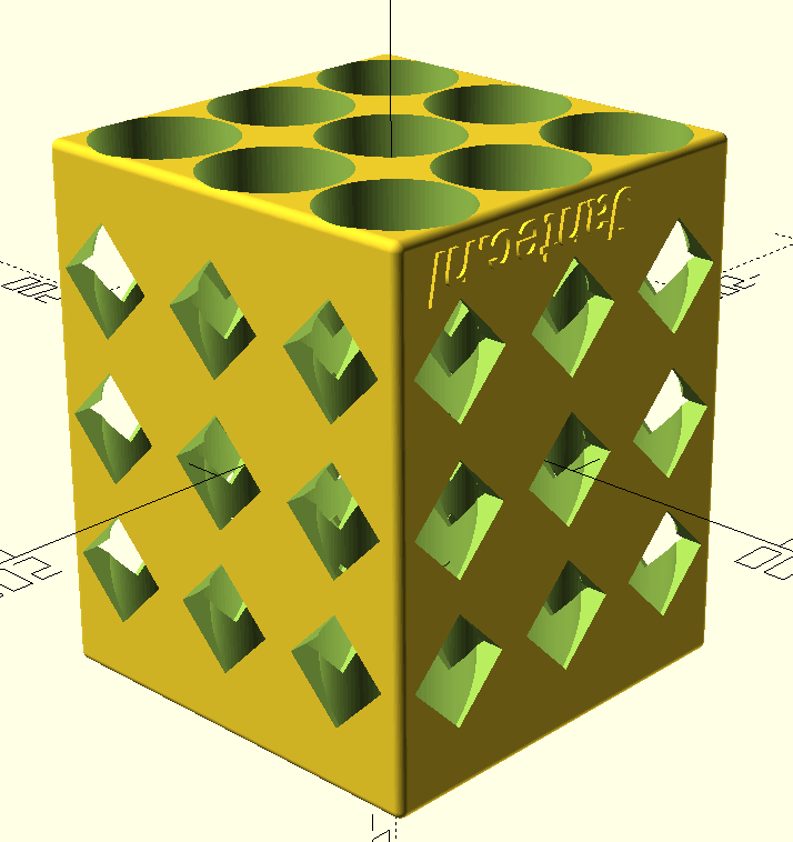
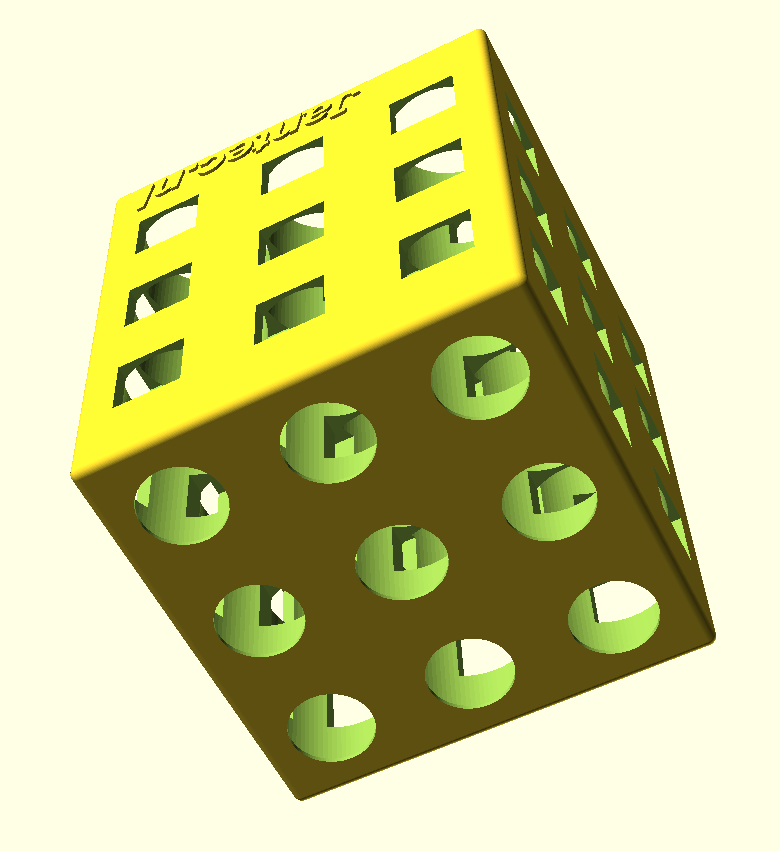
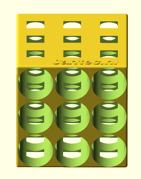
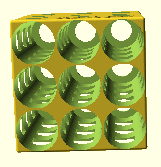
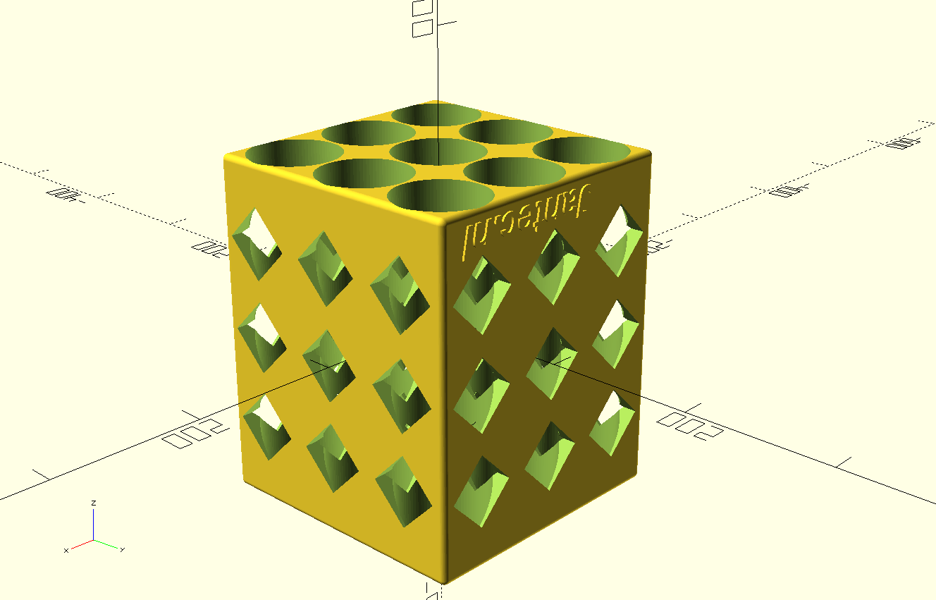
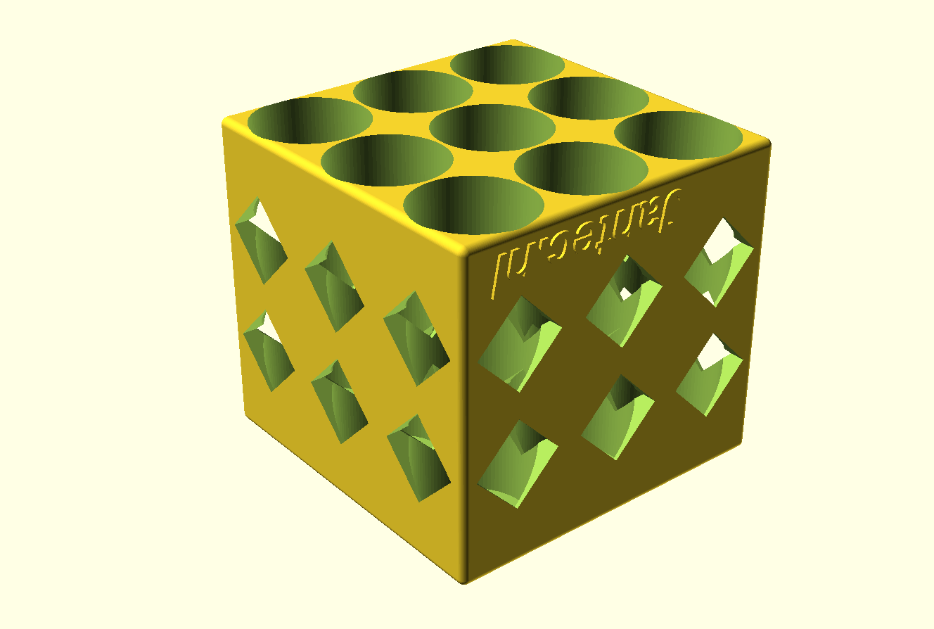
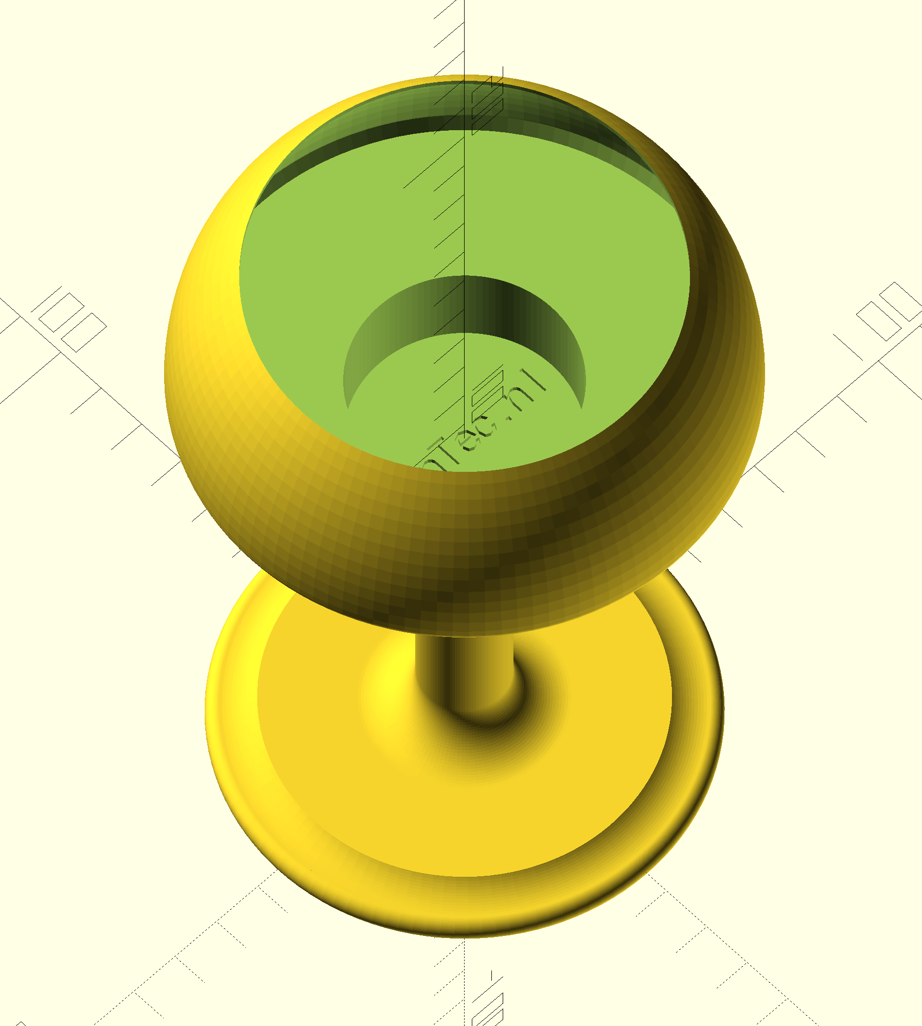
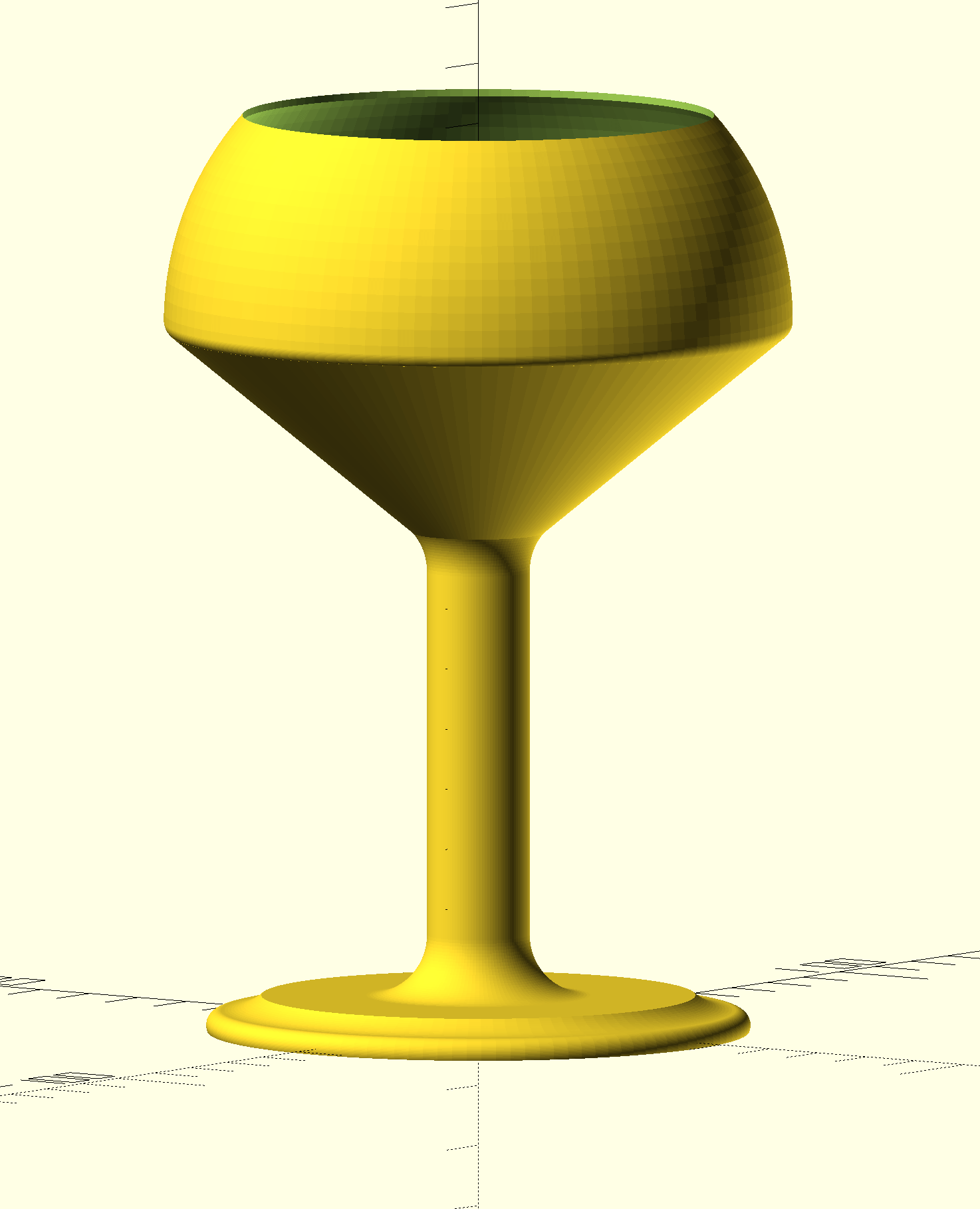
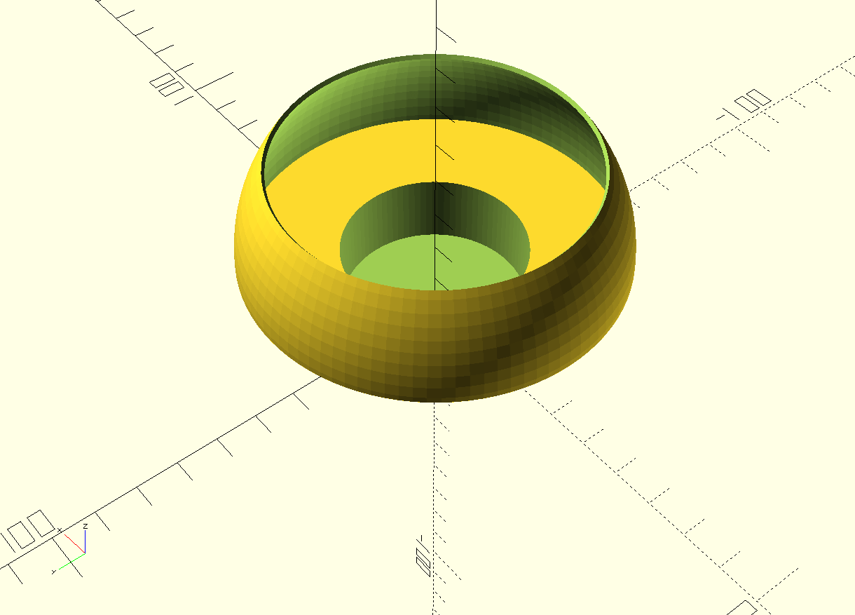
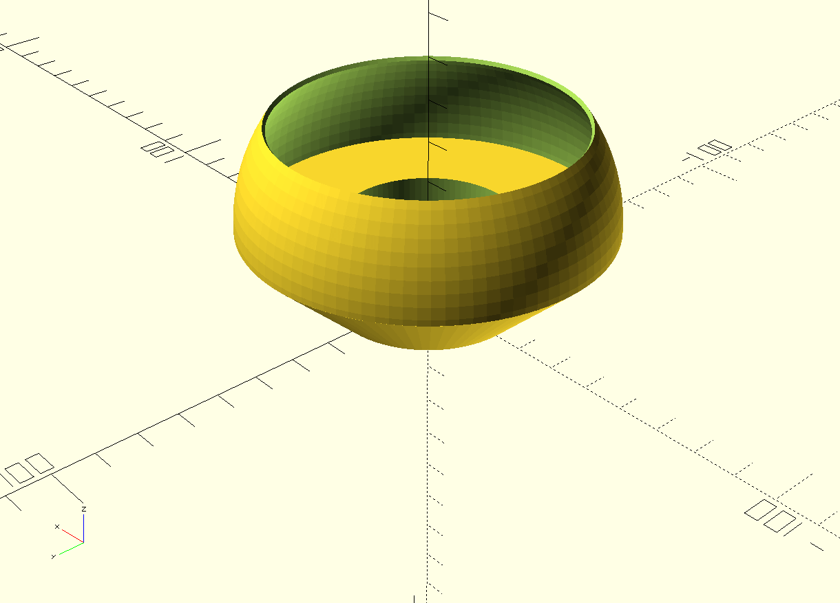
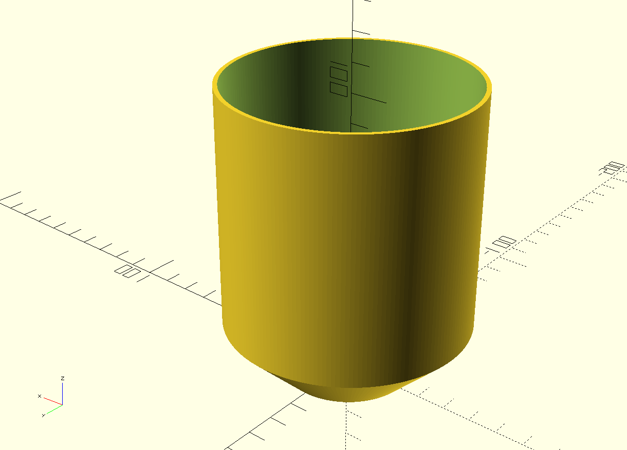
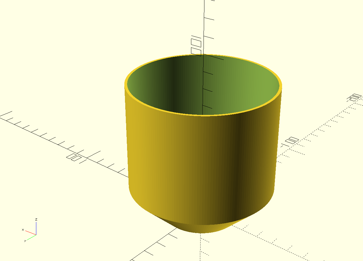
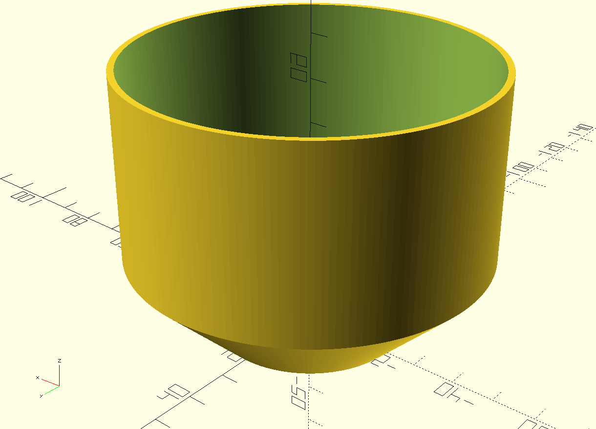
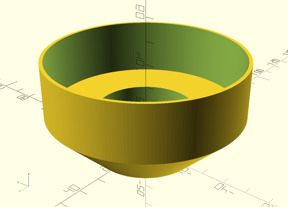
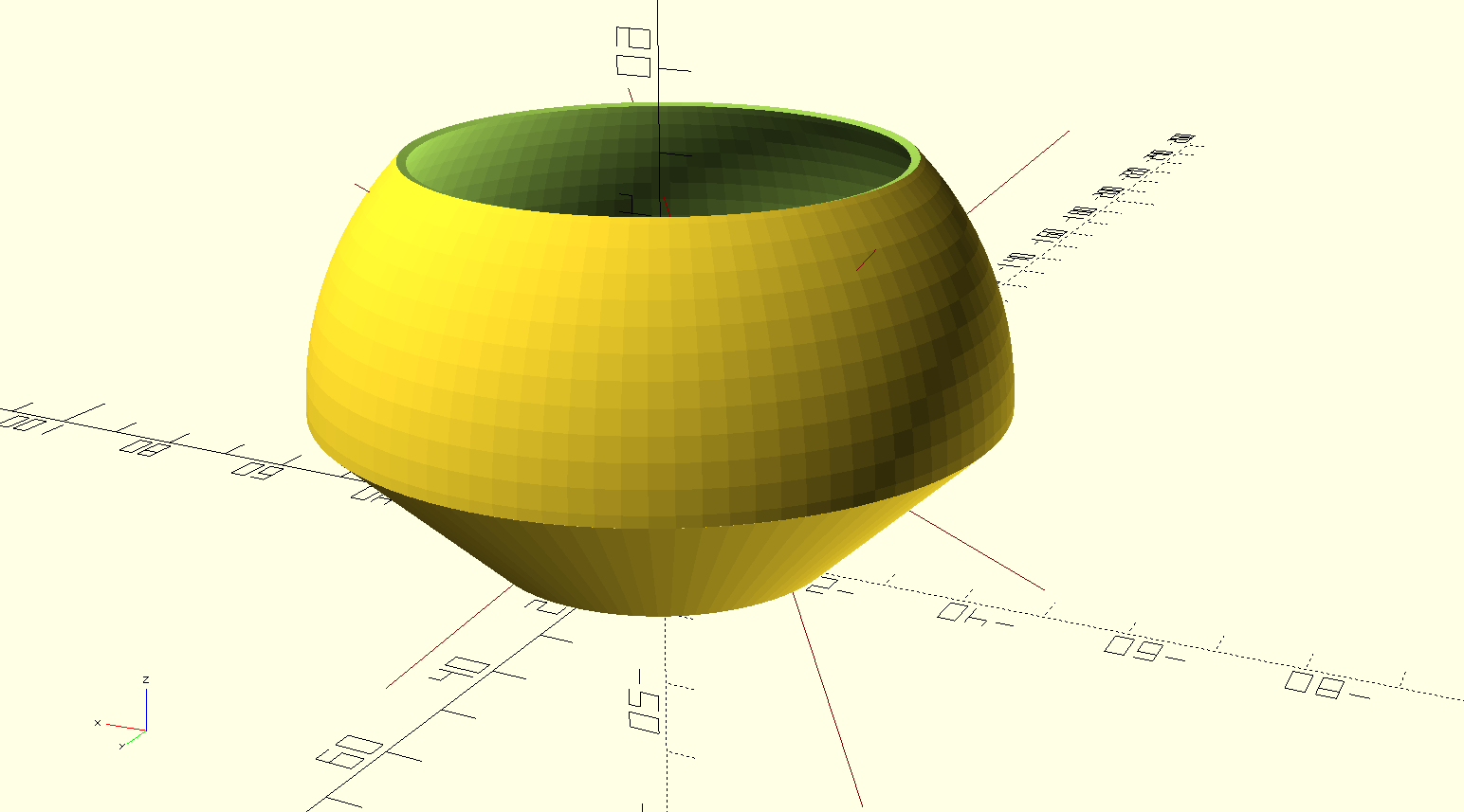
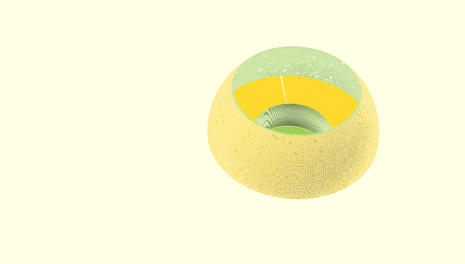
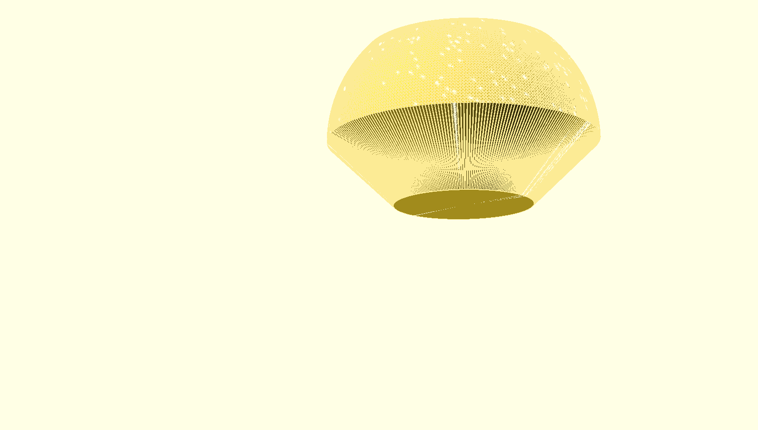
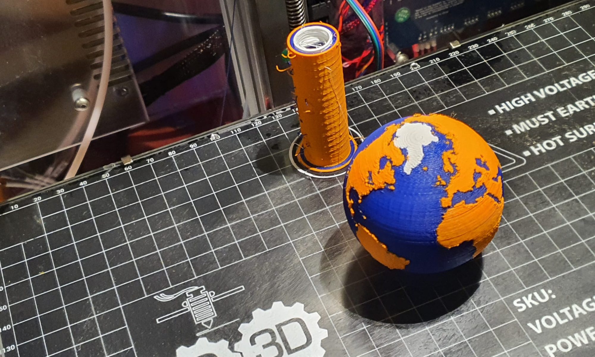
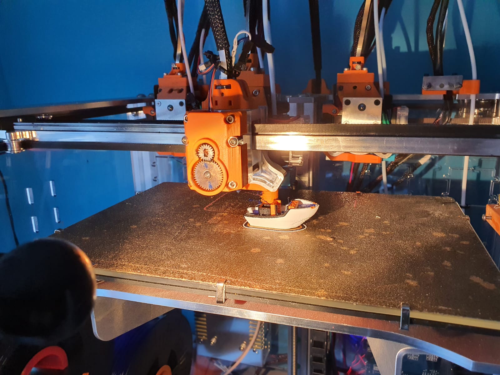
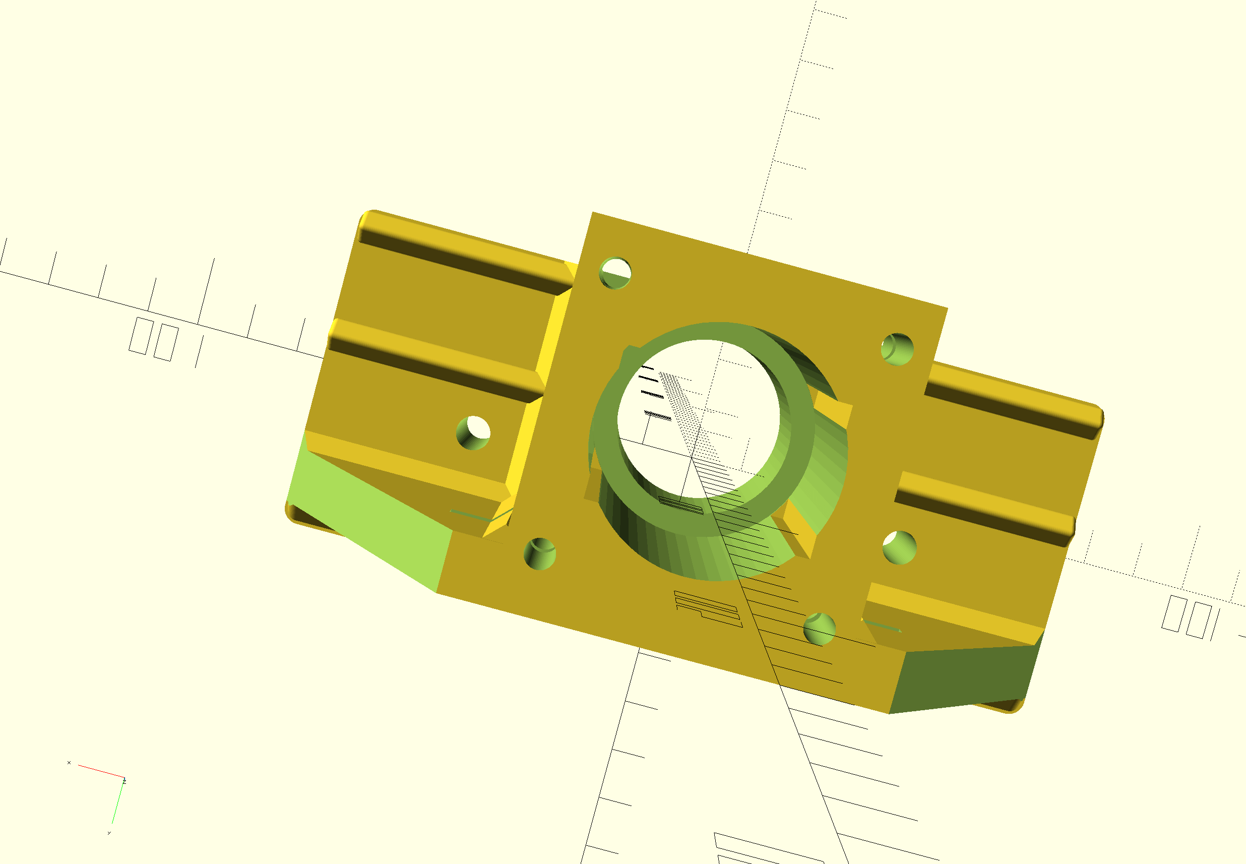
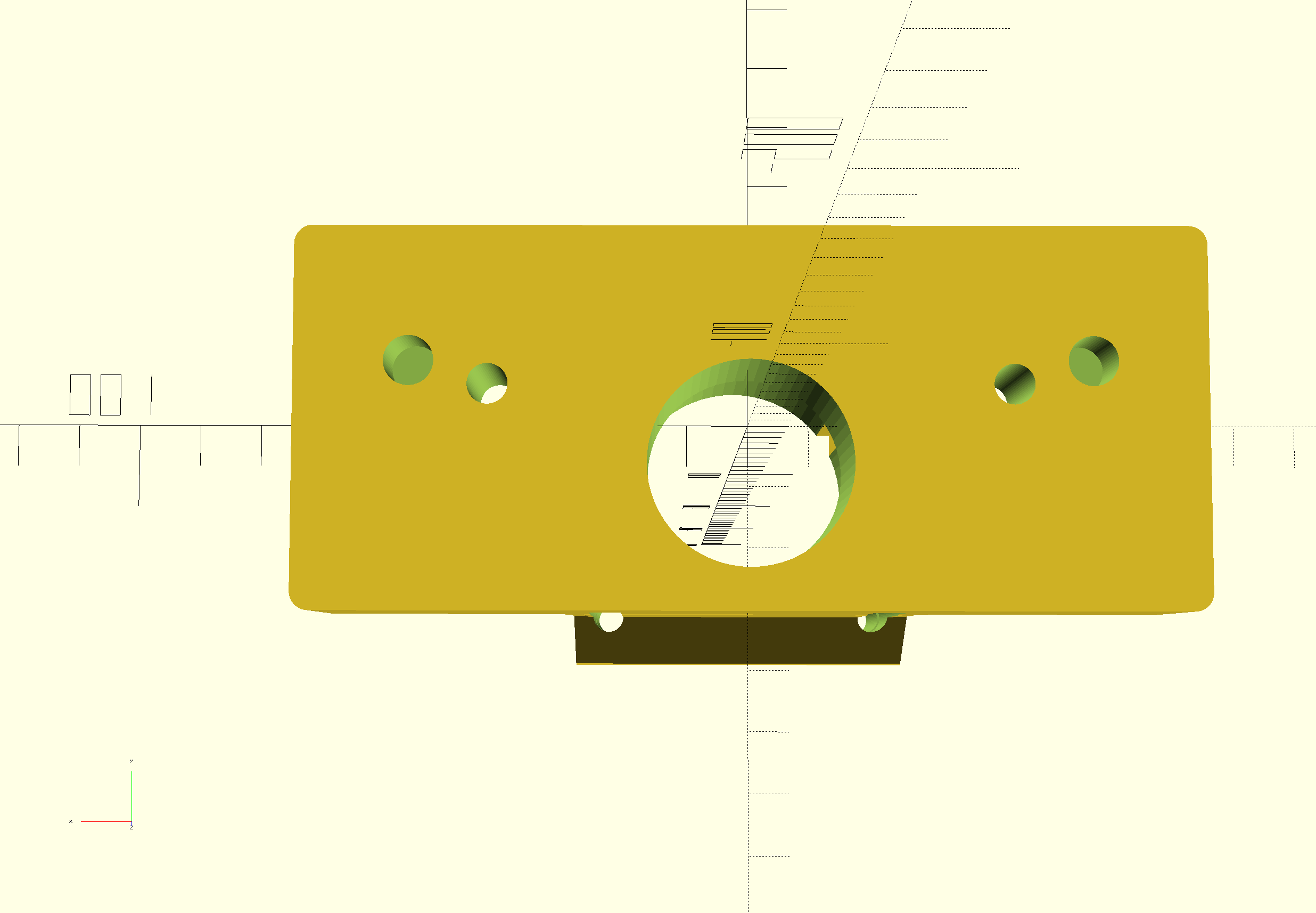
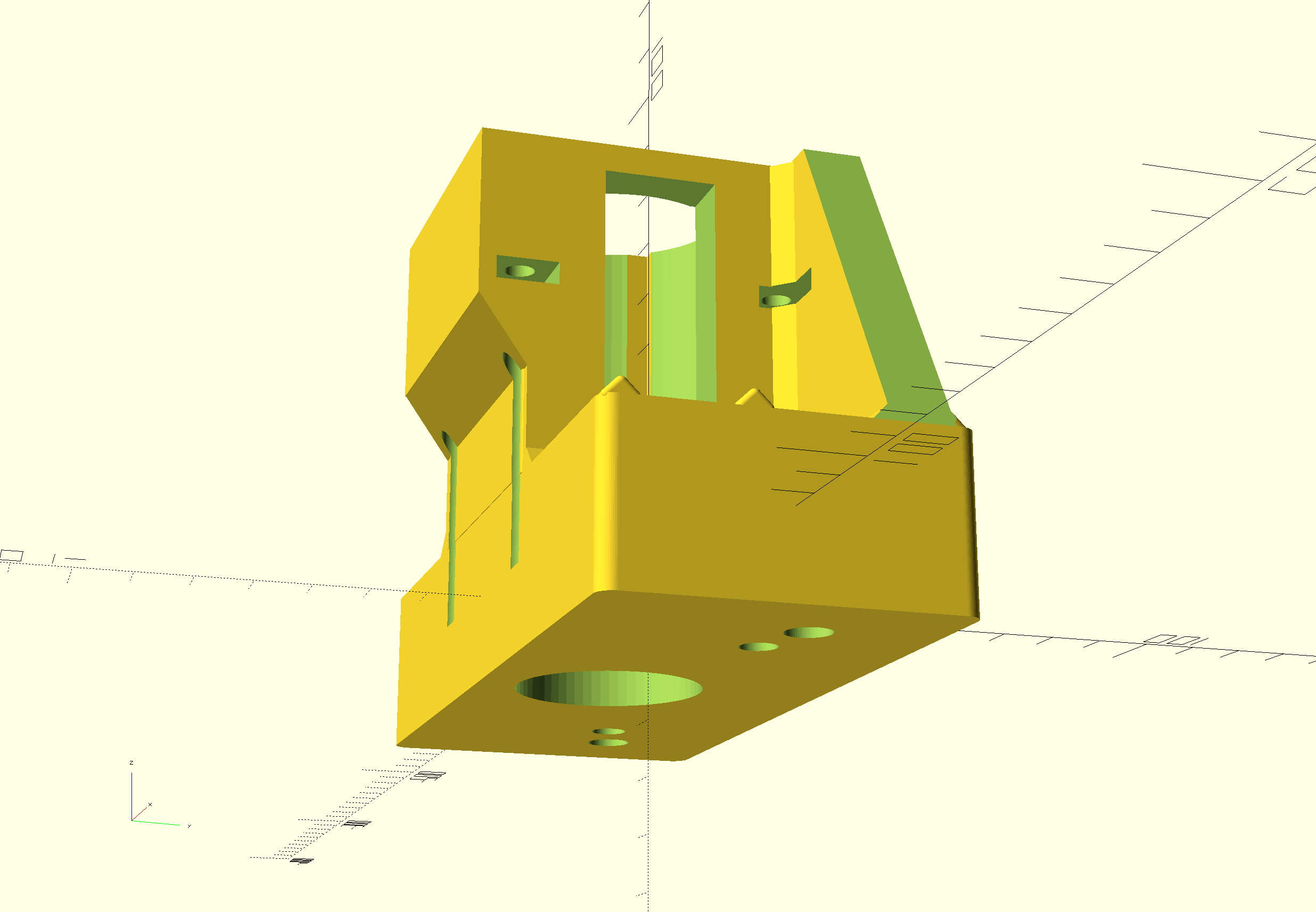
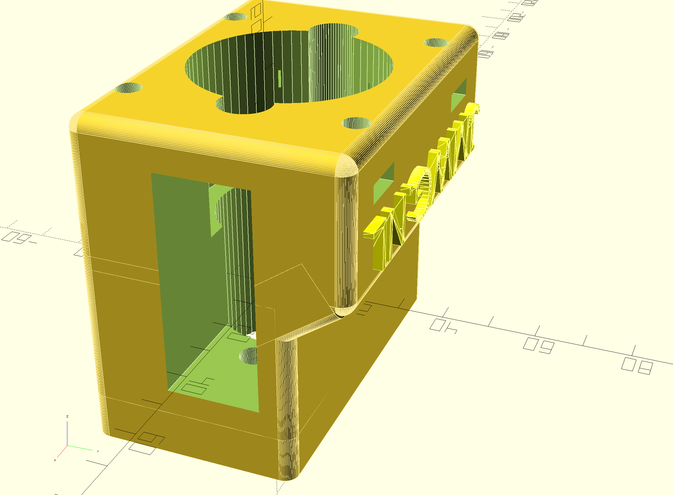
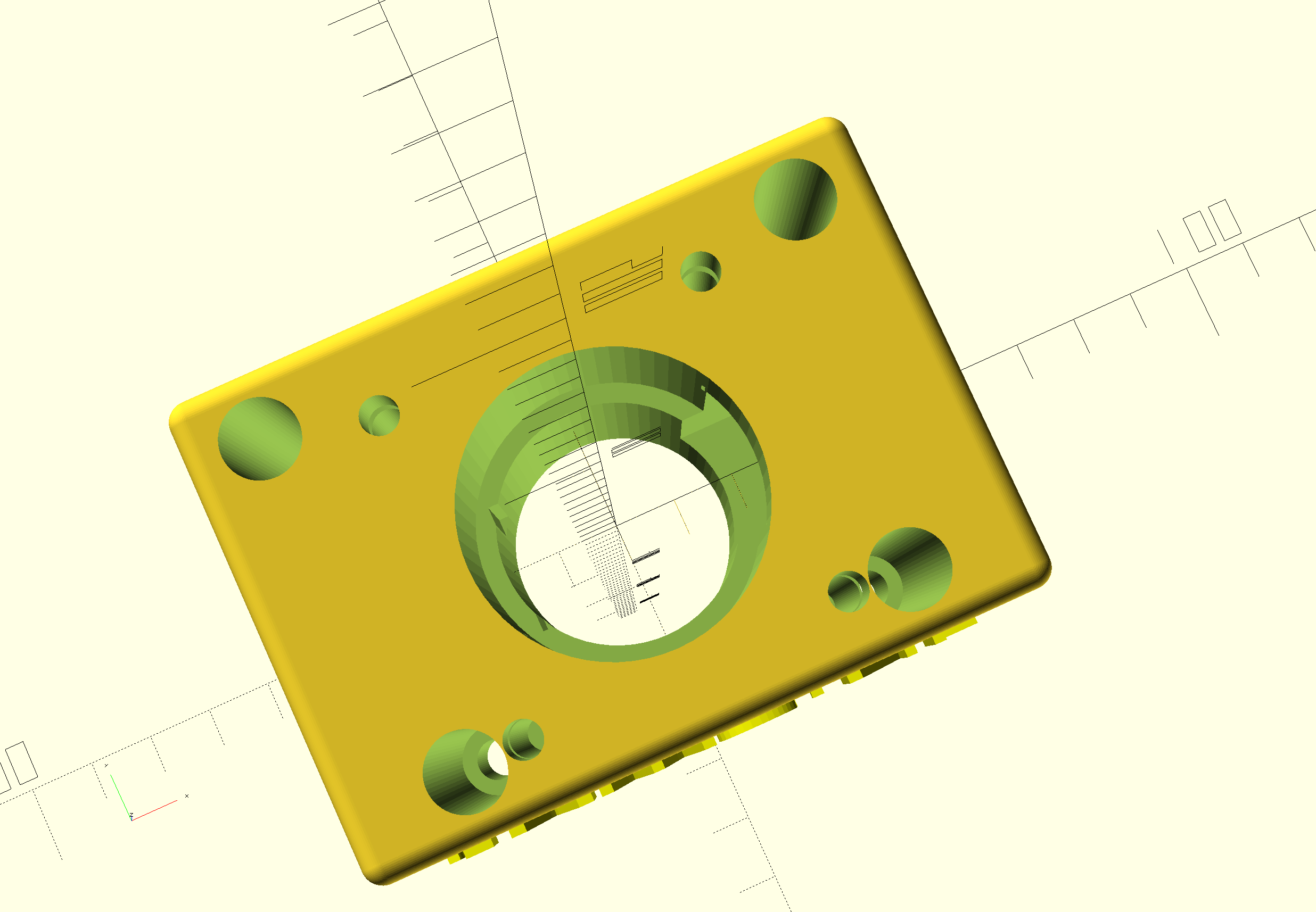
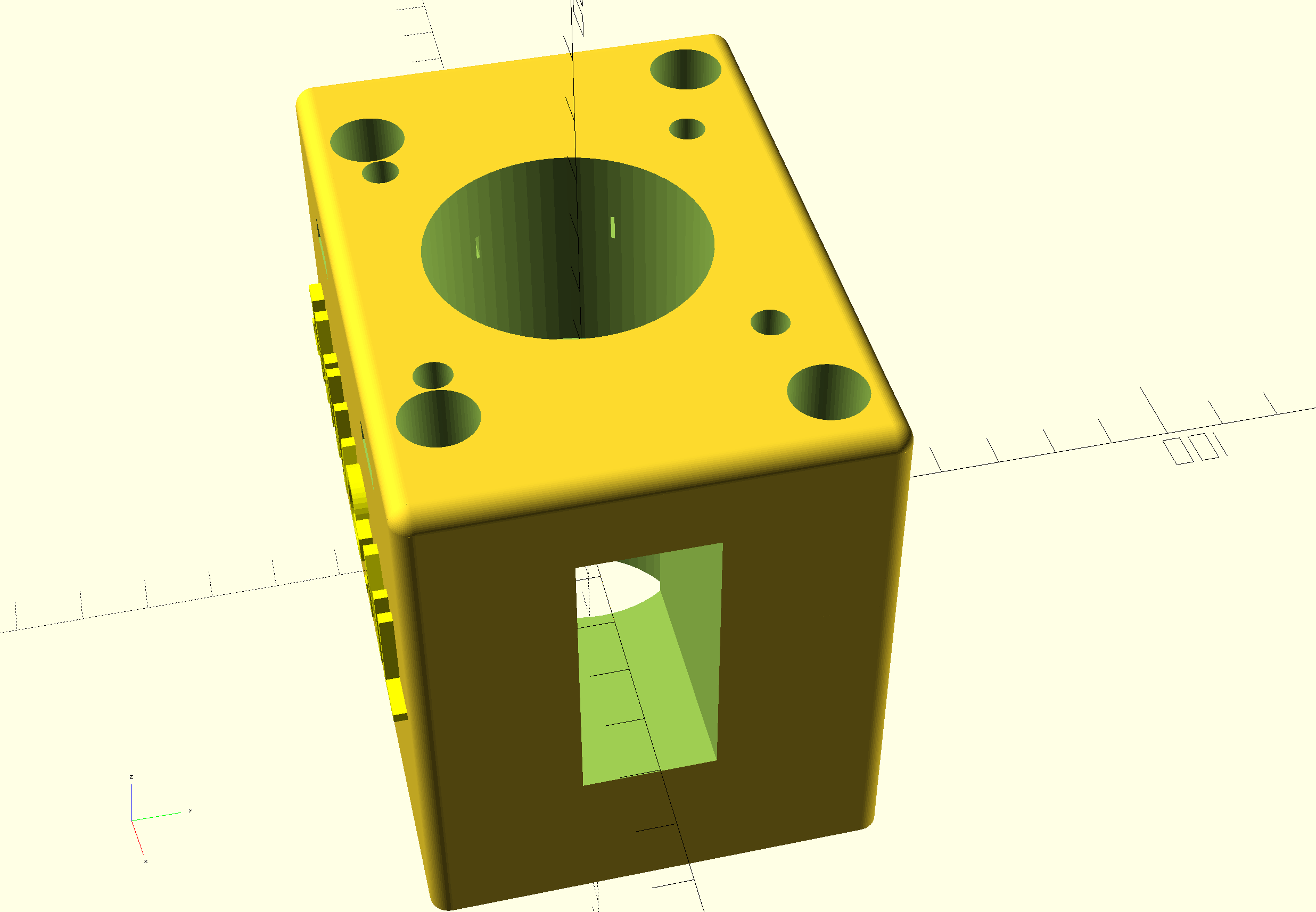
For building this nice precise clock, you can use my design files for the housing on any 3d printer that has a horizontal bed size of at least 165x165mm.
Grab both the print STL’s . HERE. from the Prusa shared site where I uploaded these designs. (If the link breaks, search on the prusa site for ws2812 circular arduino clock).
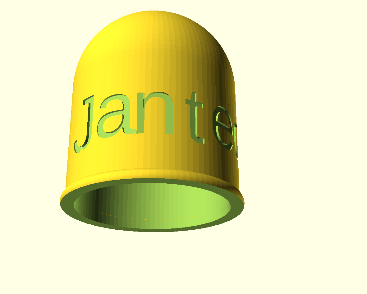
OR get the STL file for the clock’s FRONT from my website HERE
AND get the STL file for the clock’s REAR from my website HERE
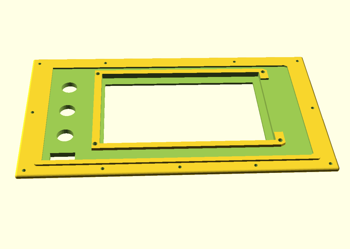
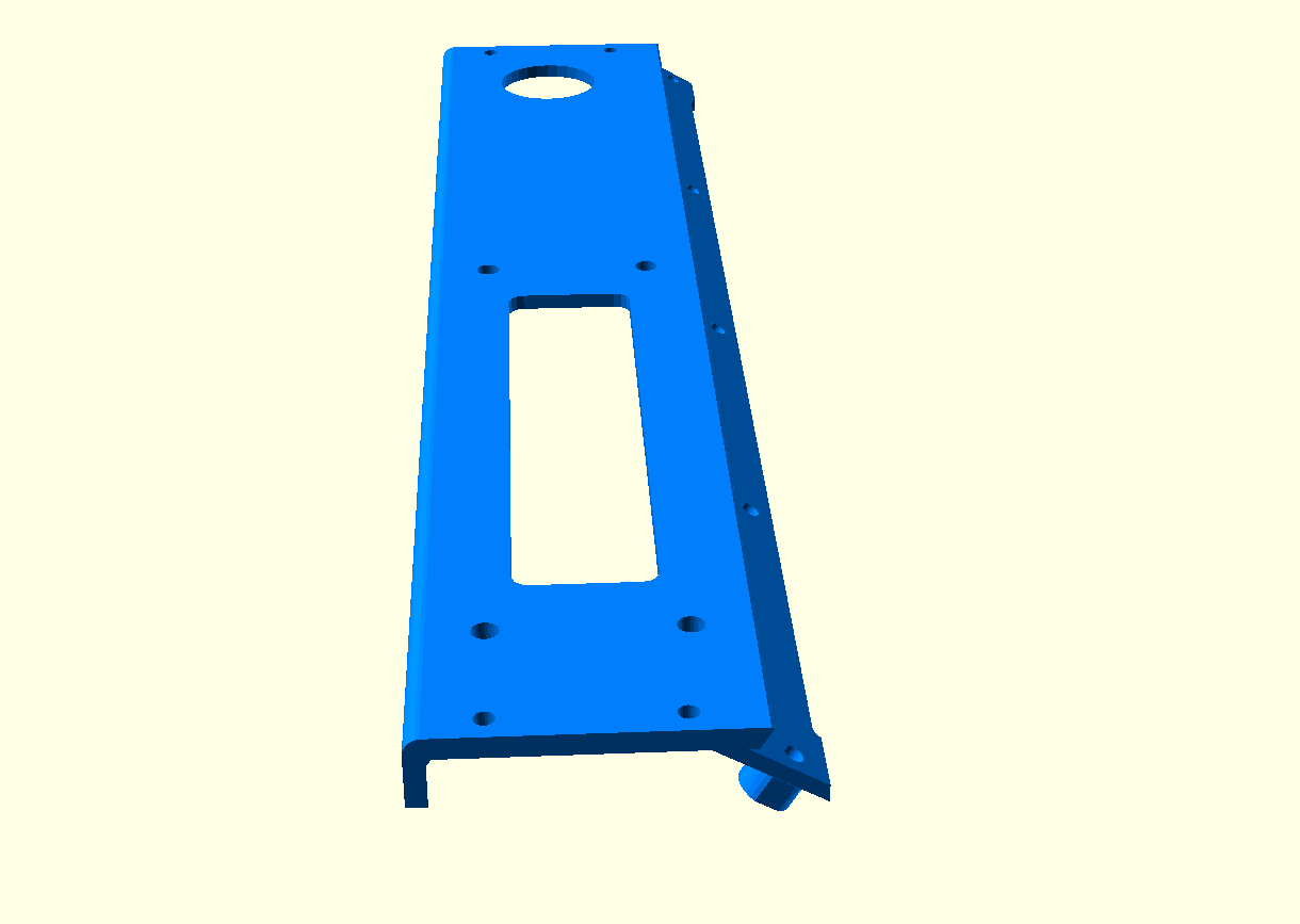
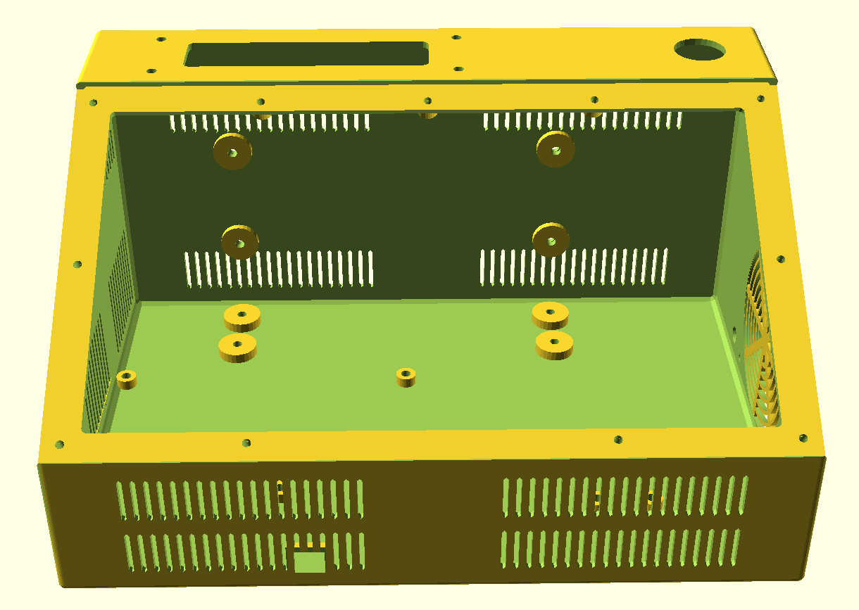
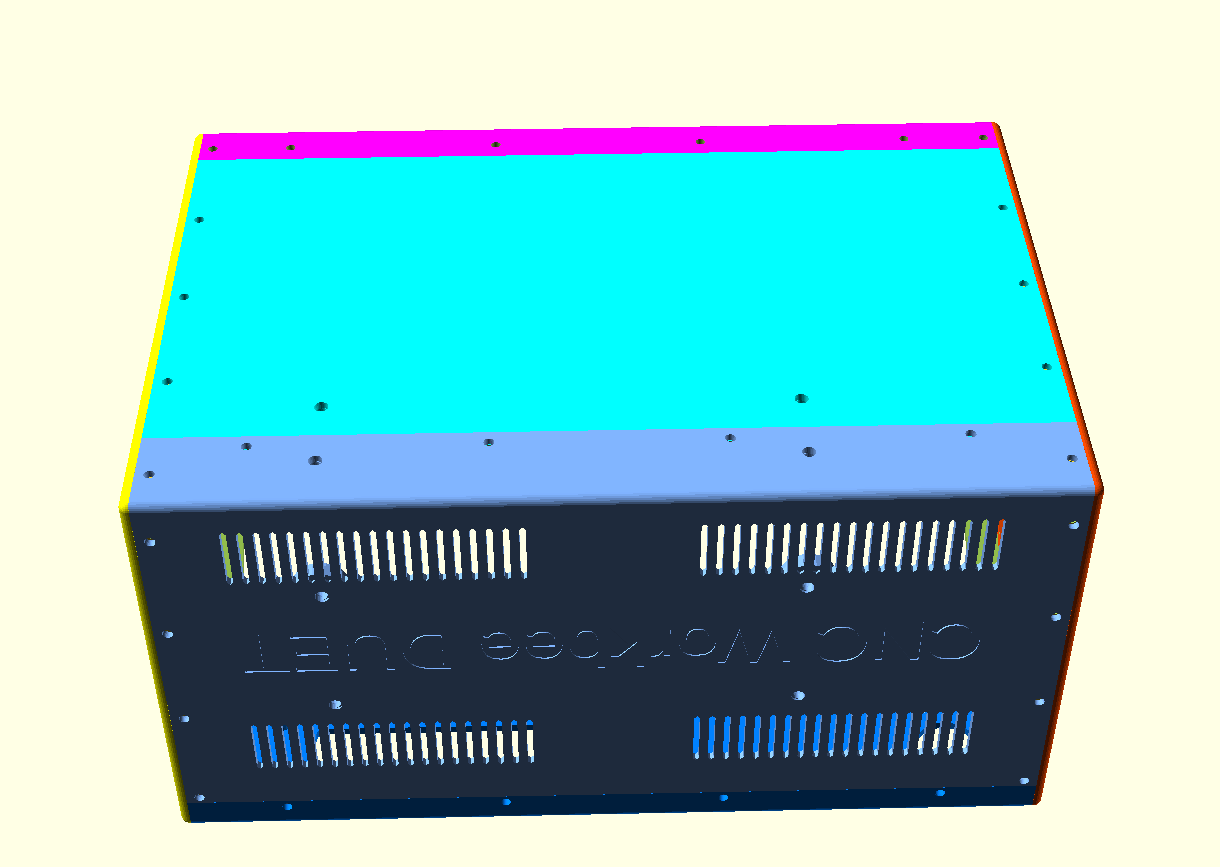
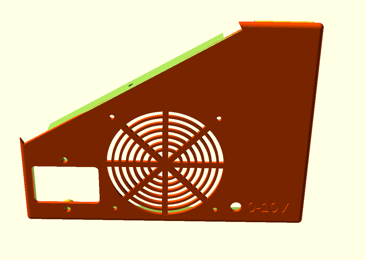
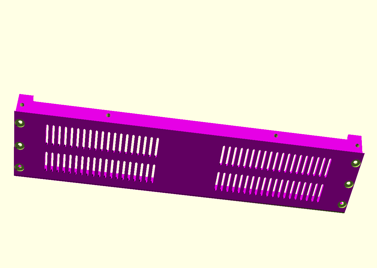
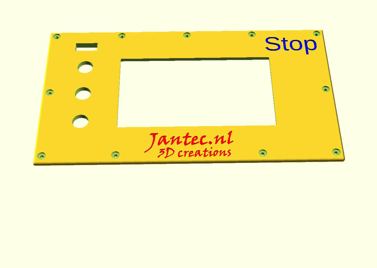
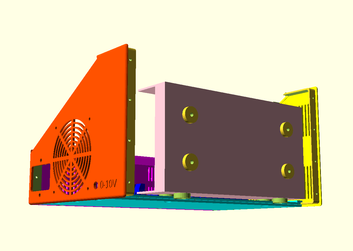
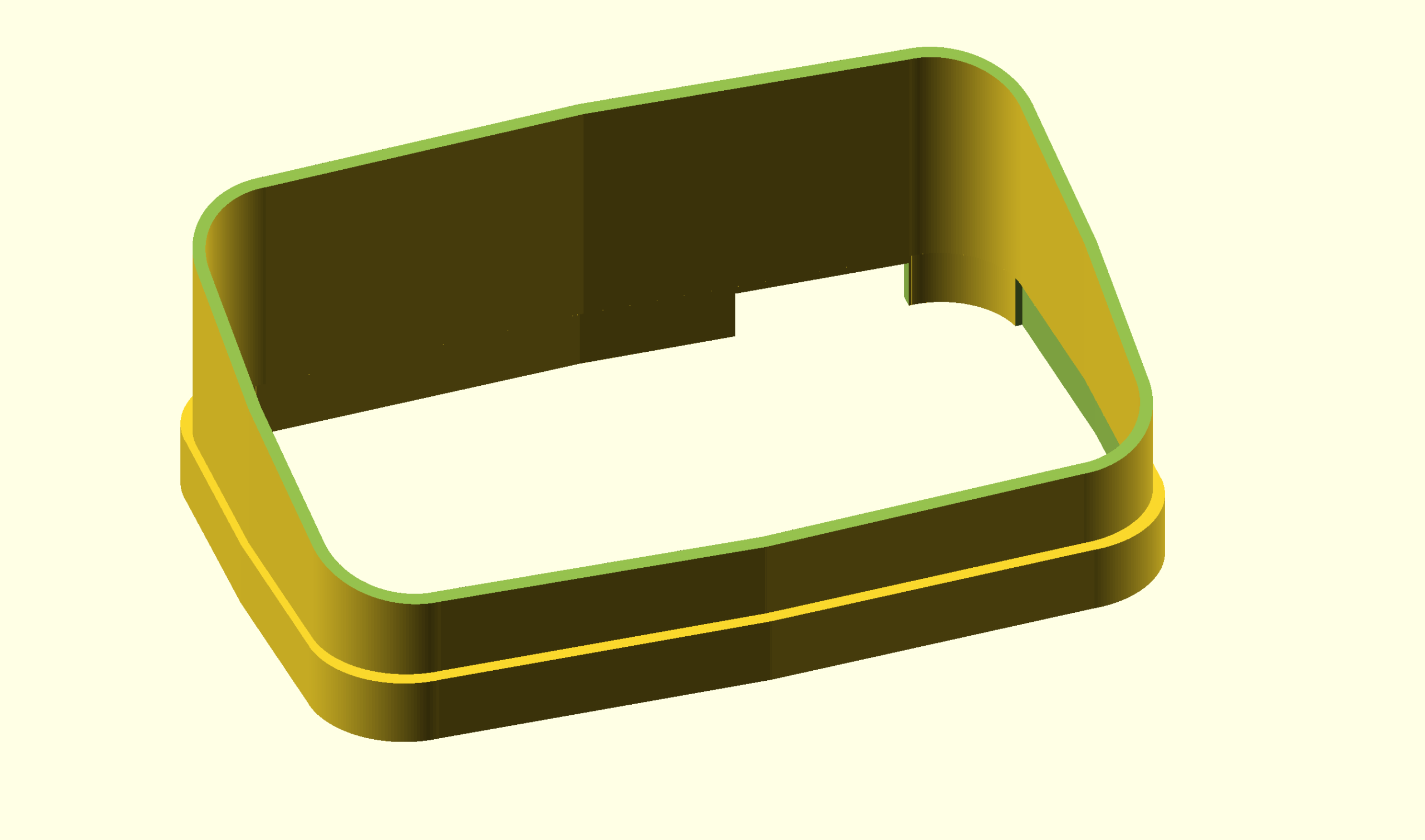
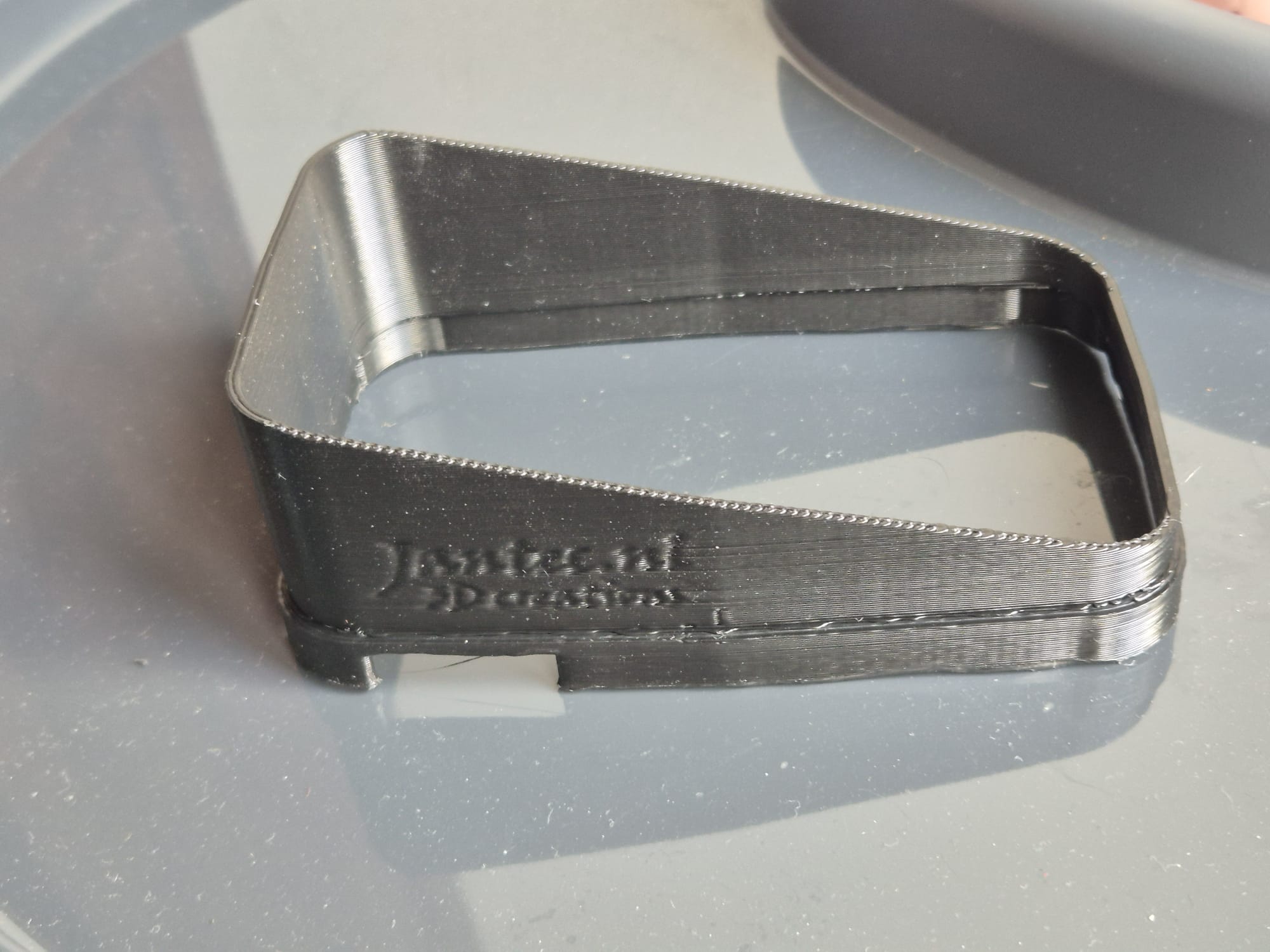
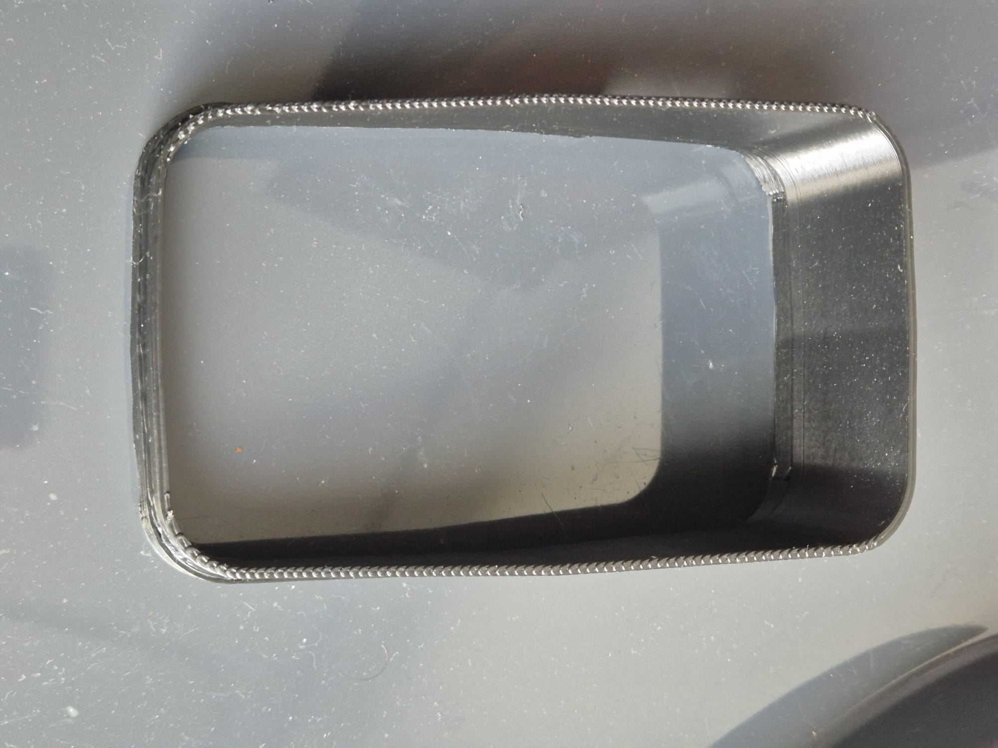
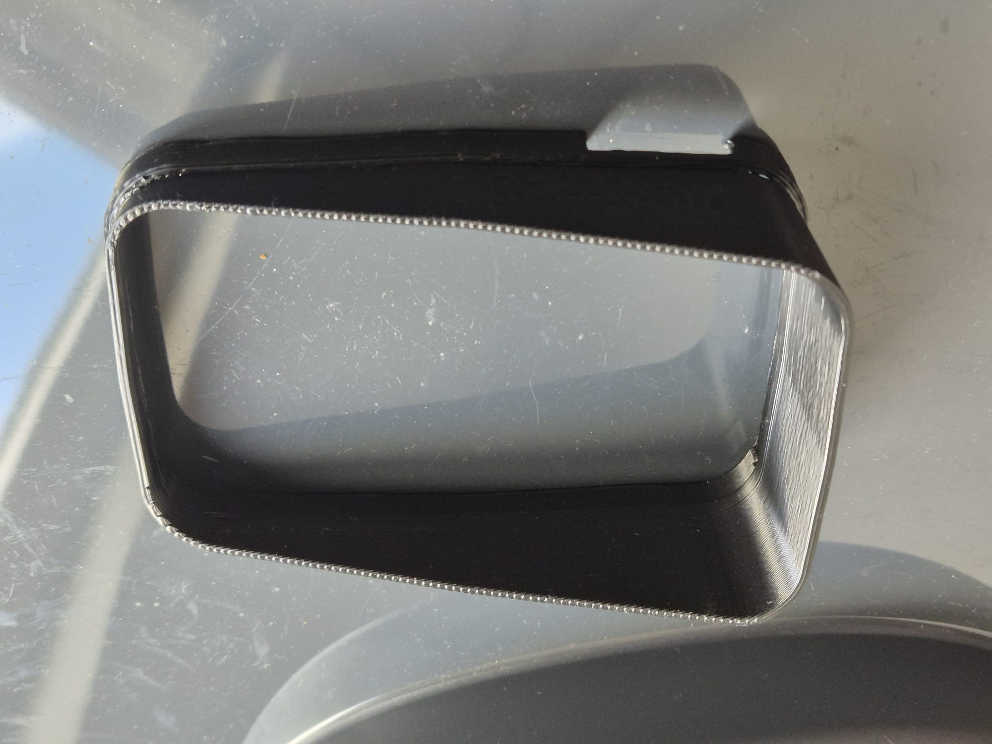
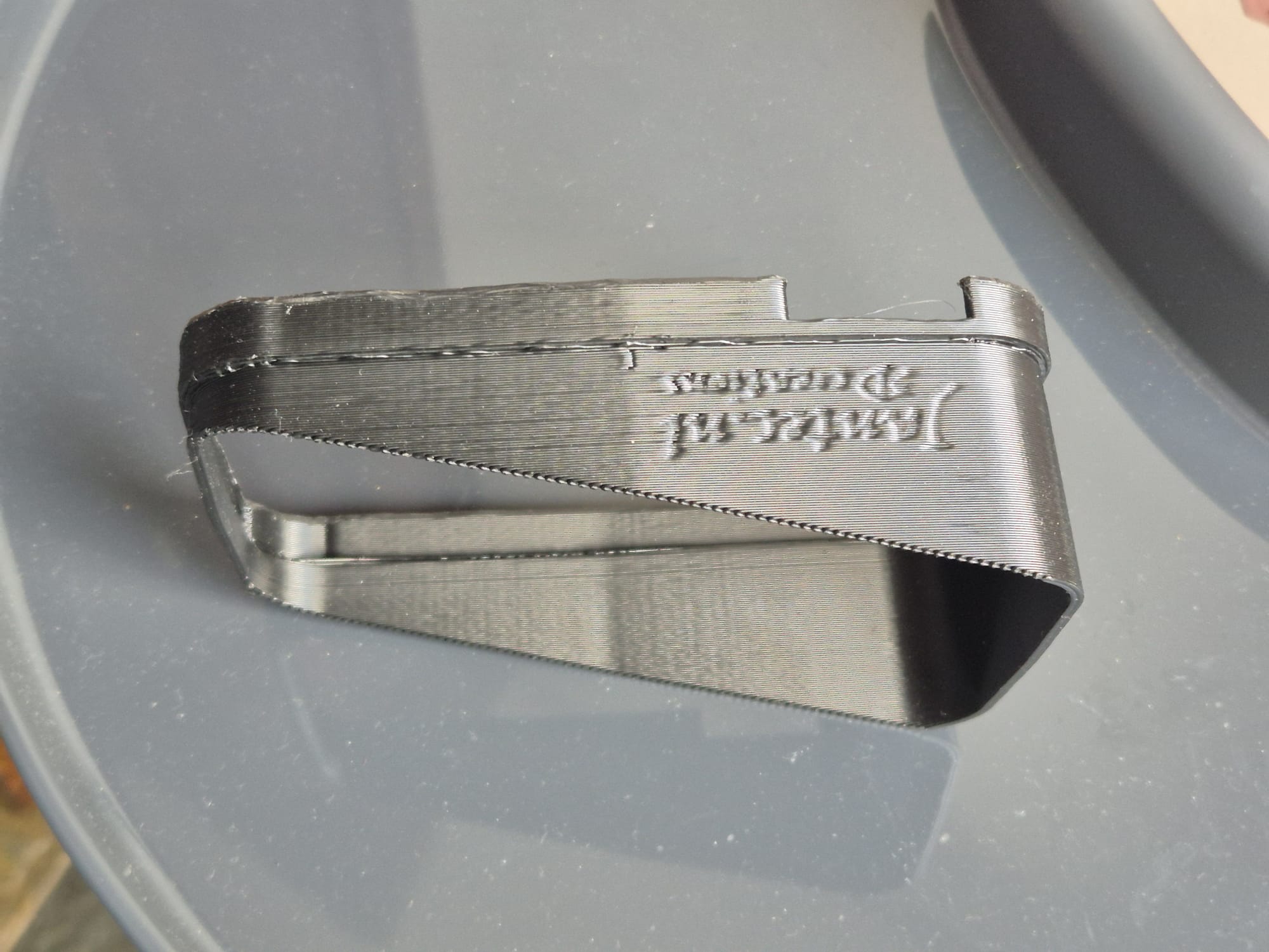
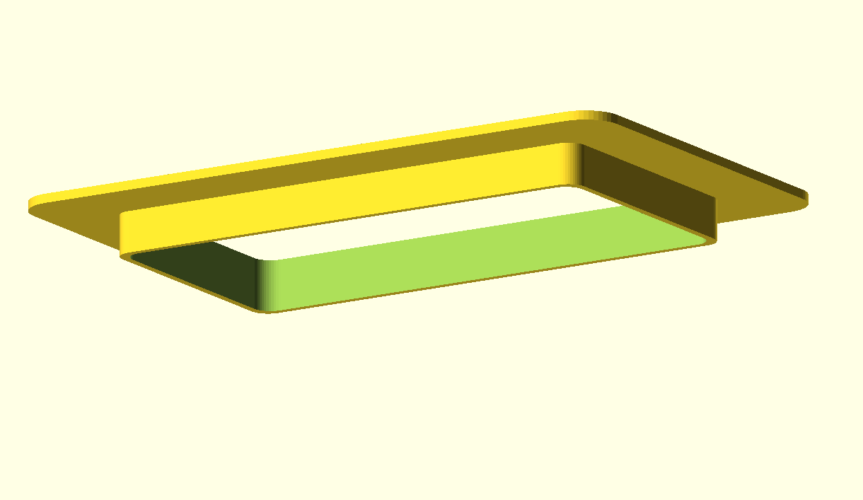
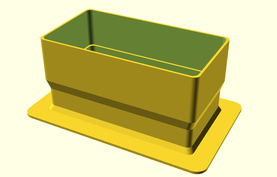
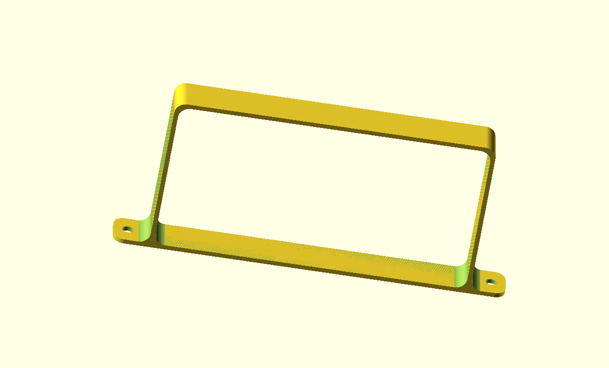
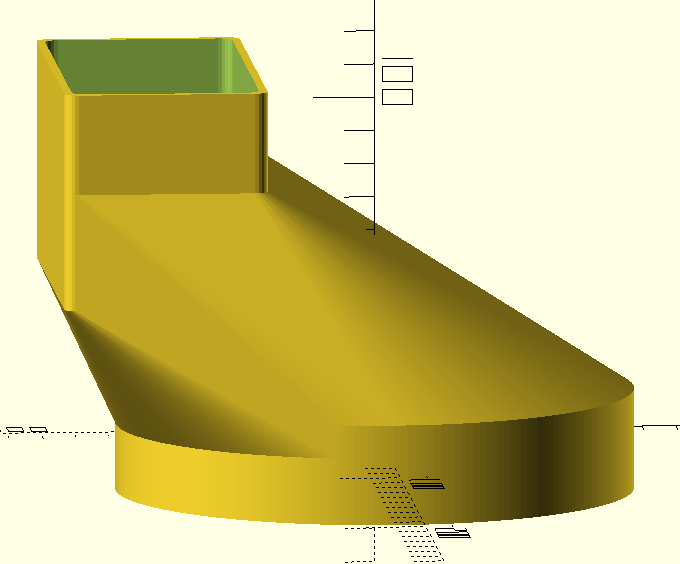
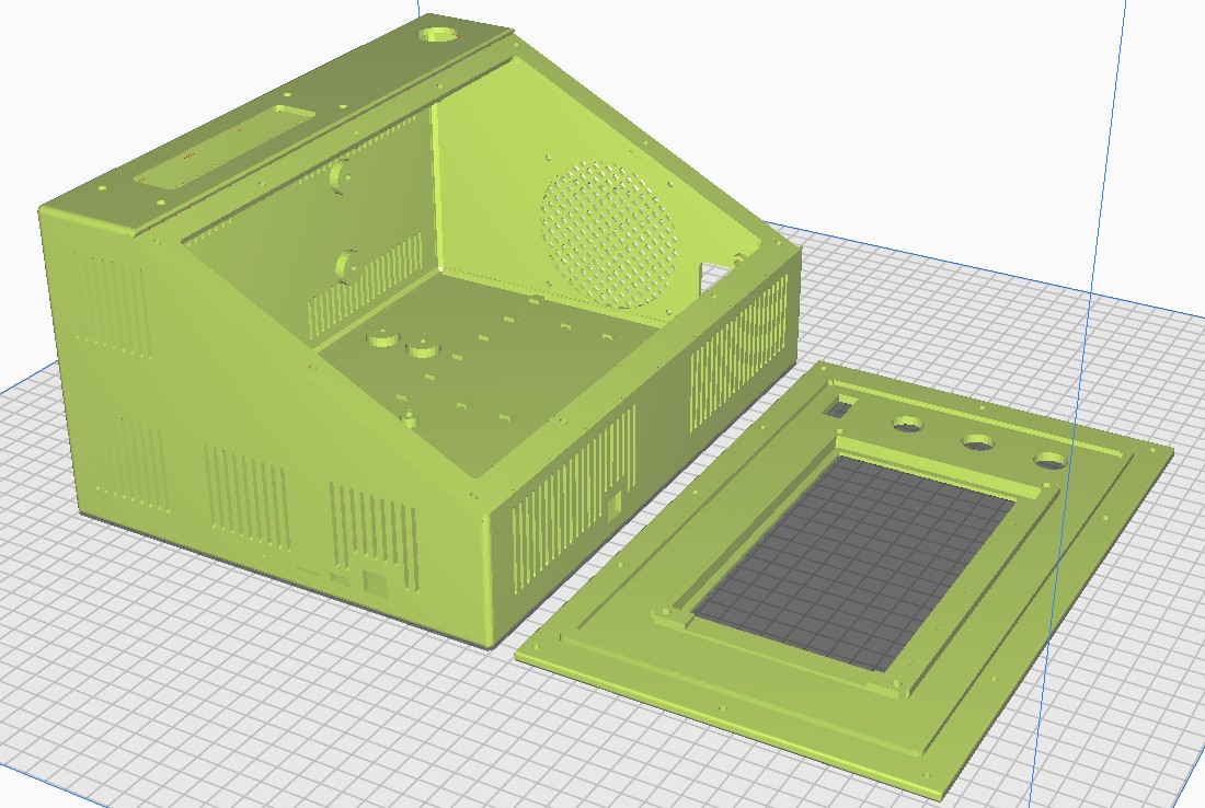
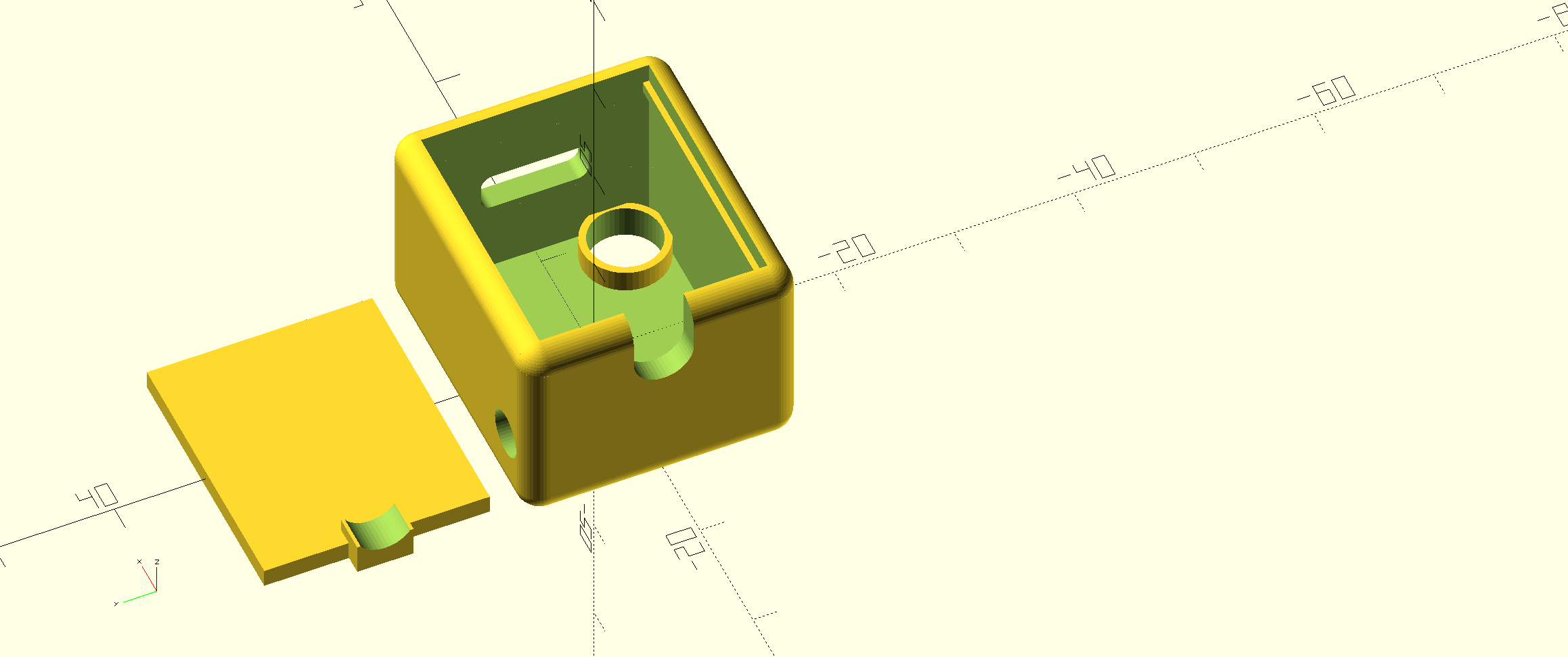
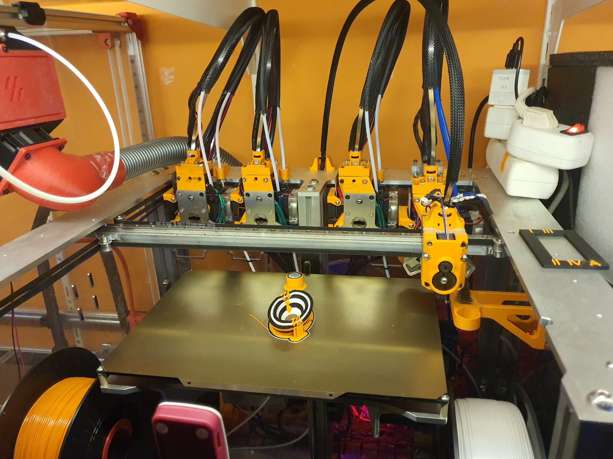
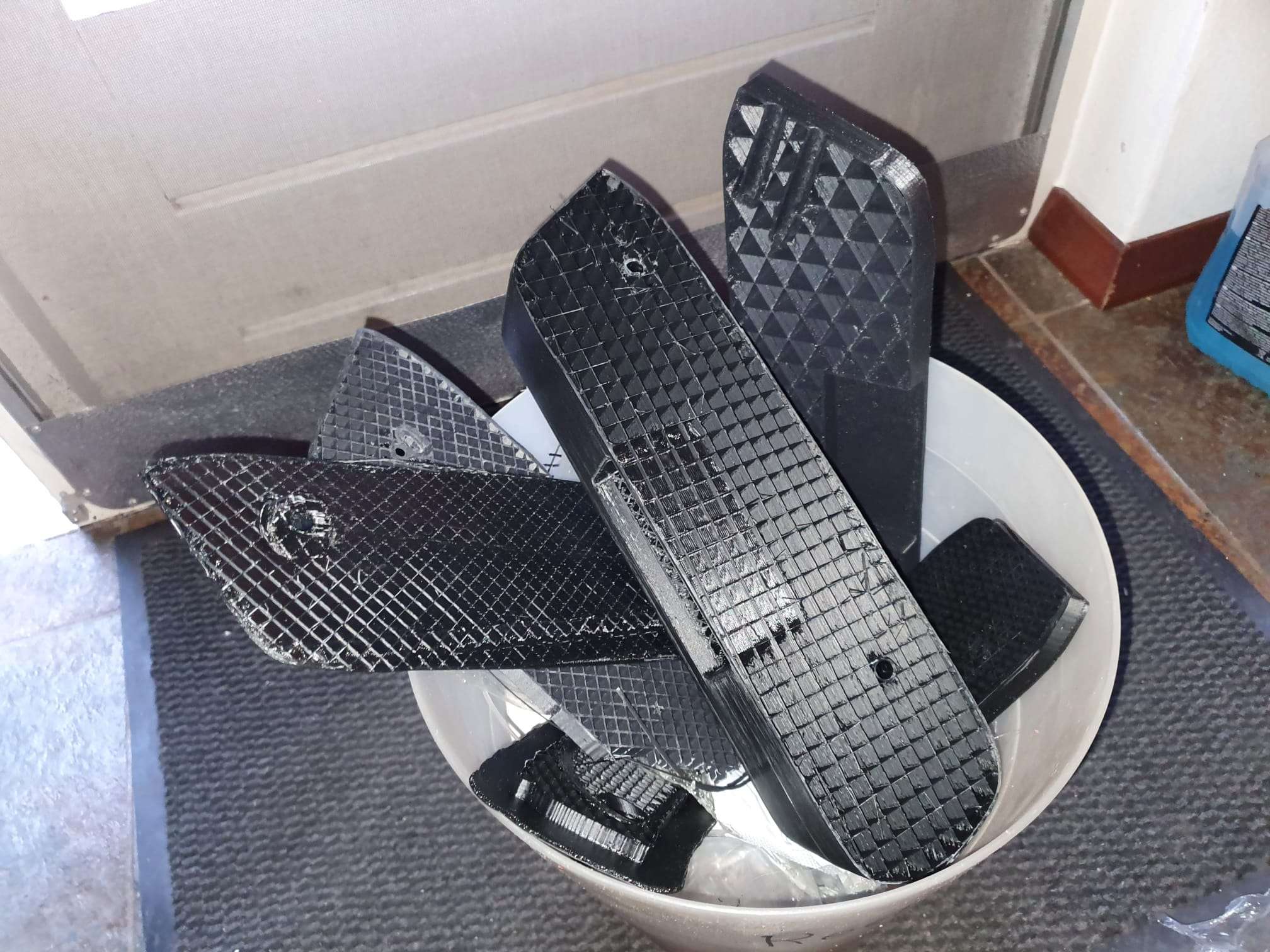
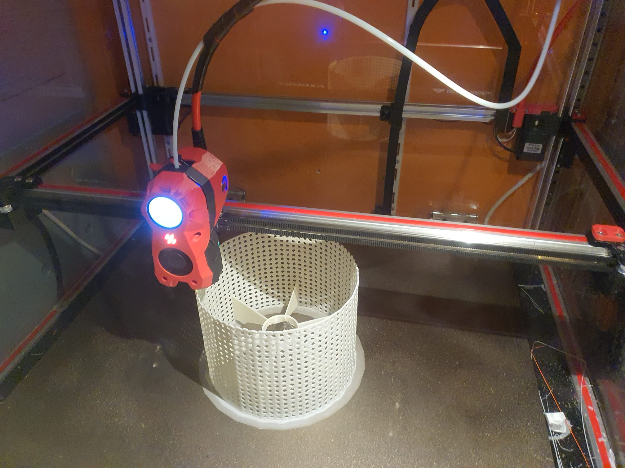
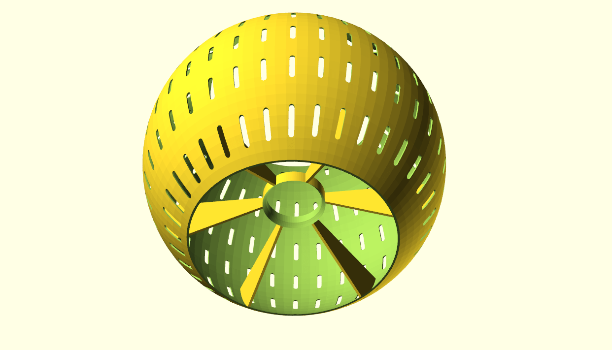
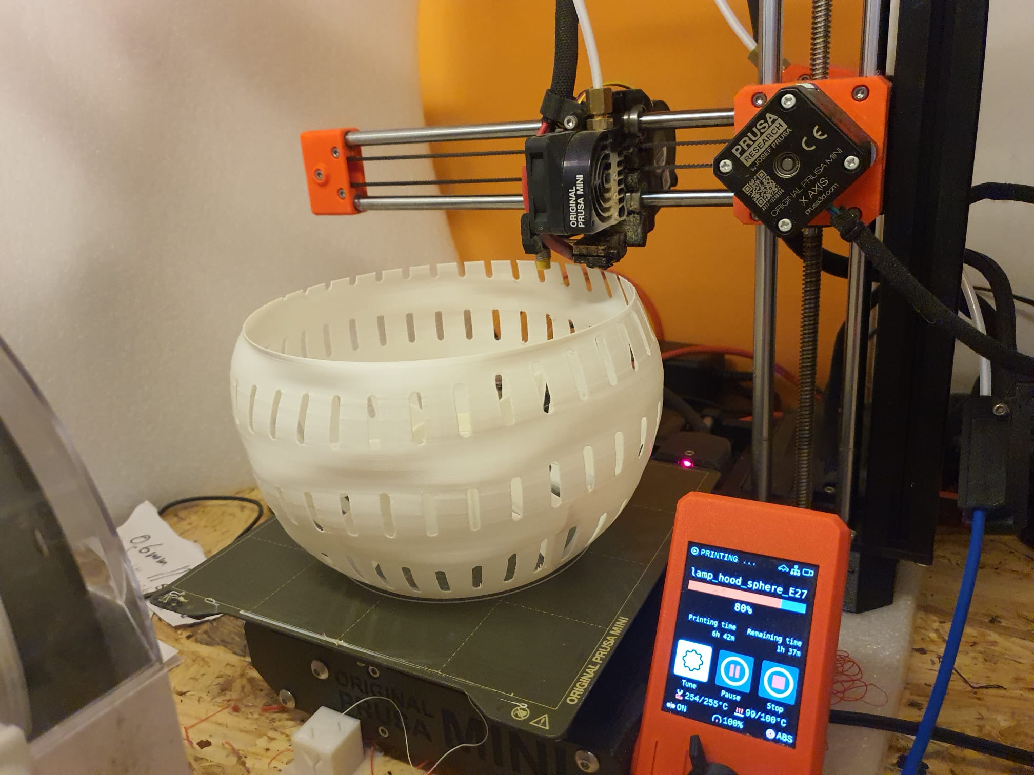
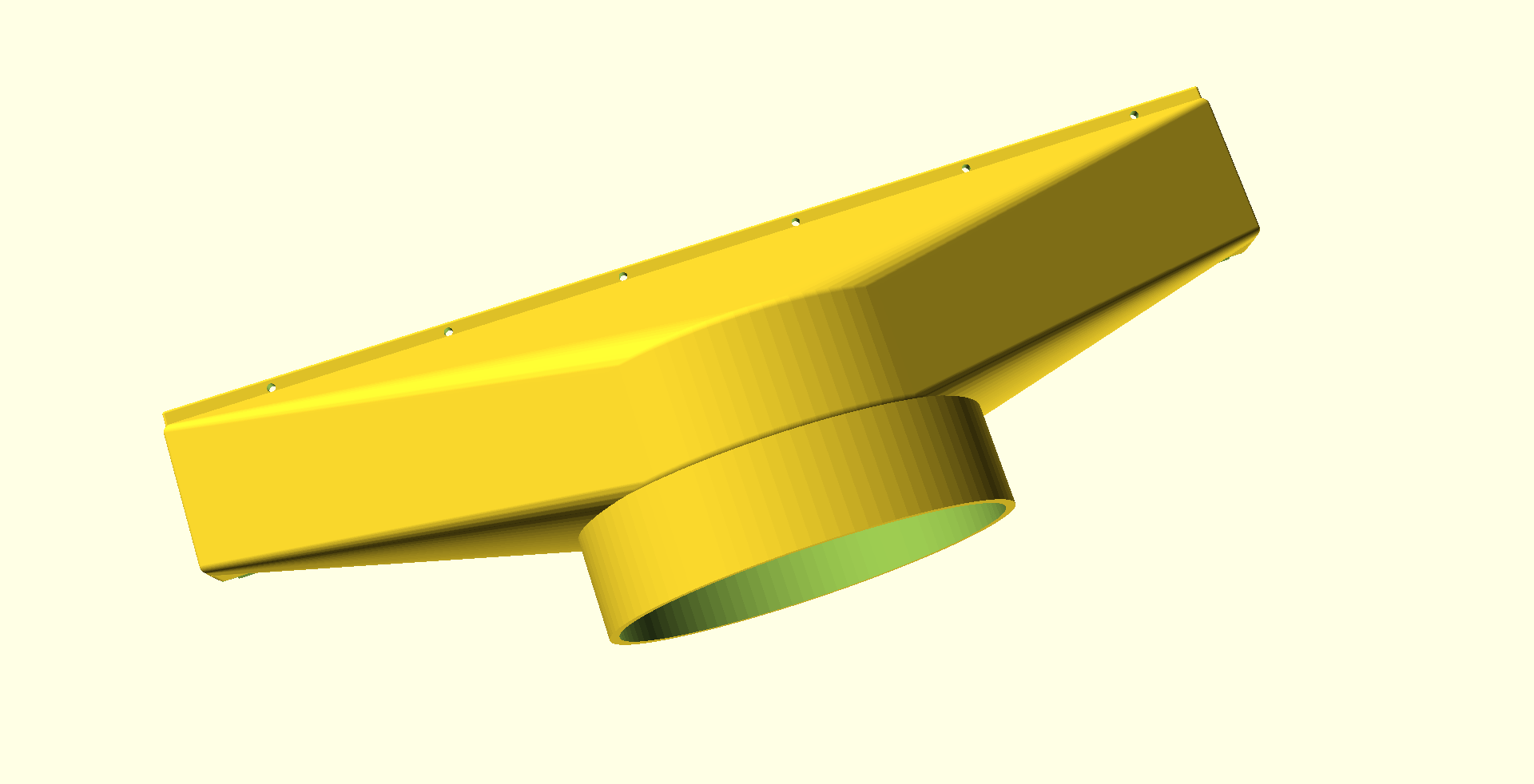
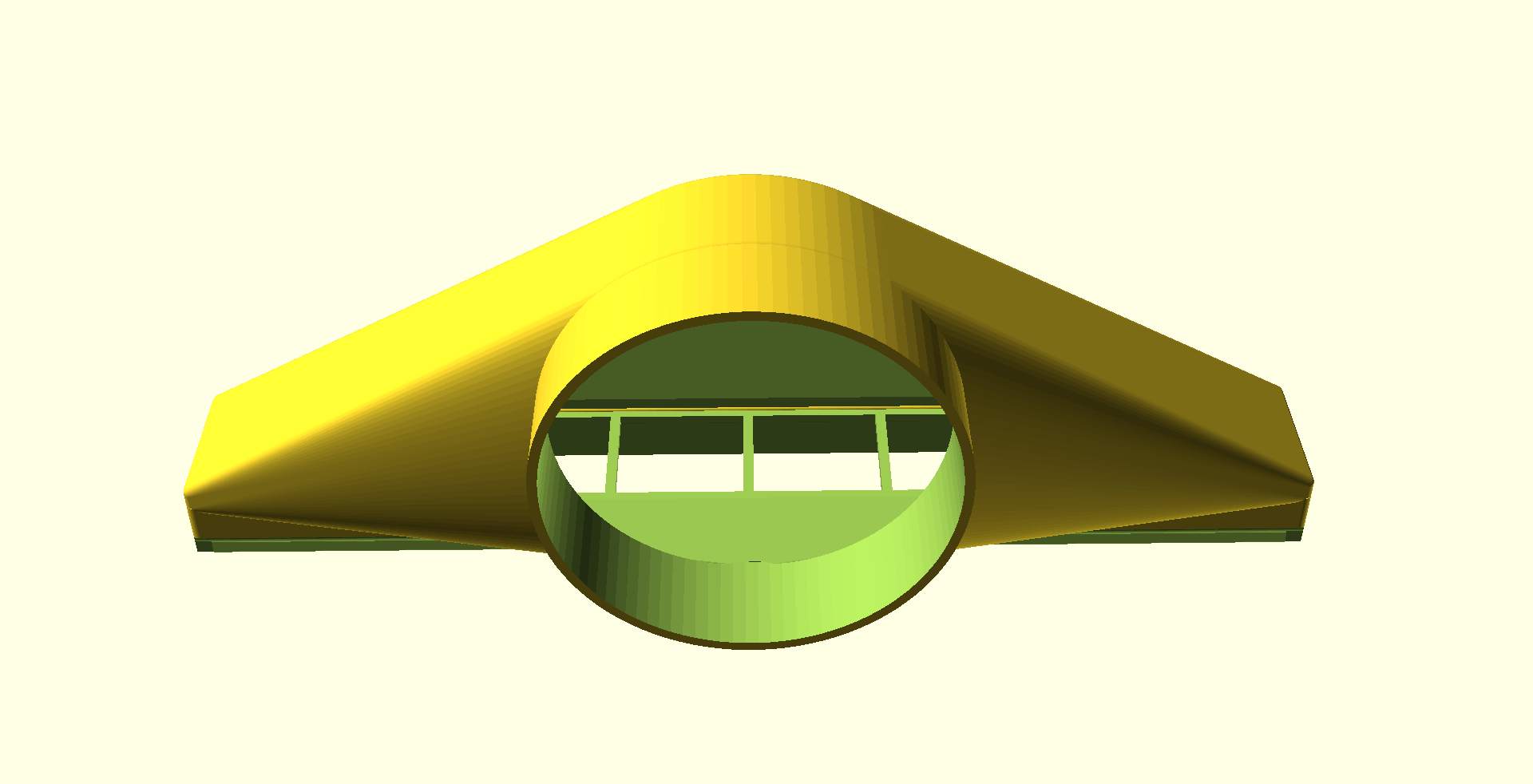
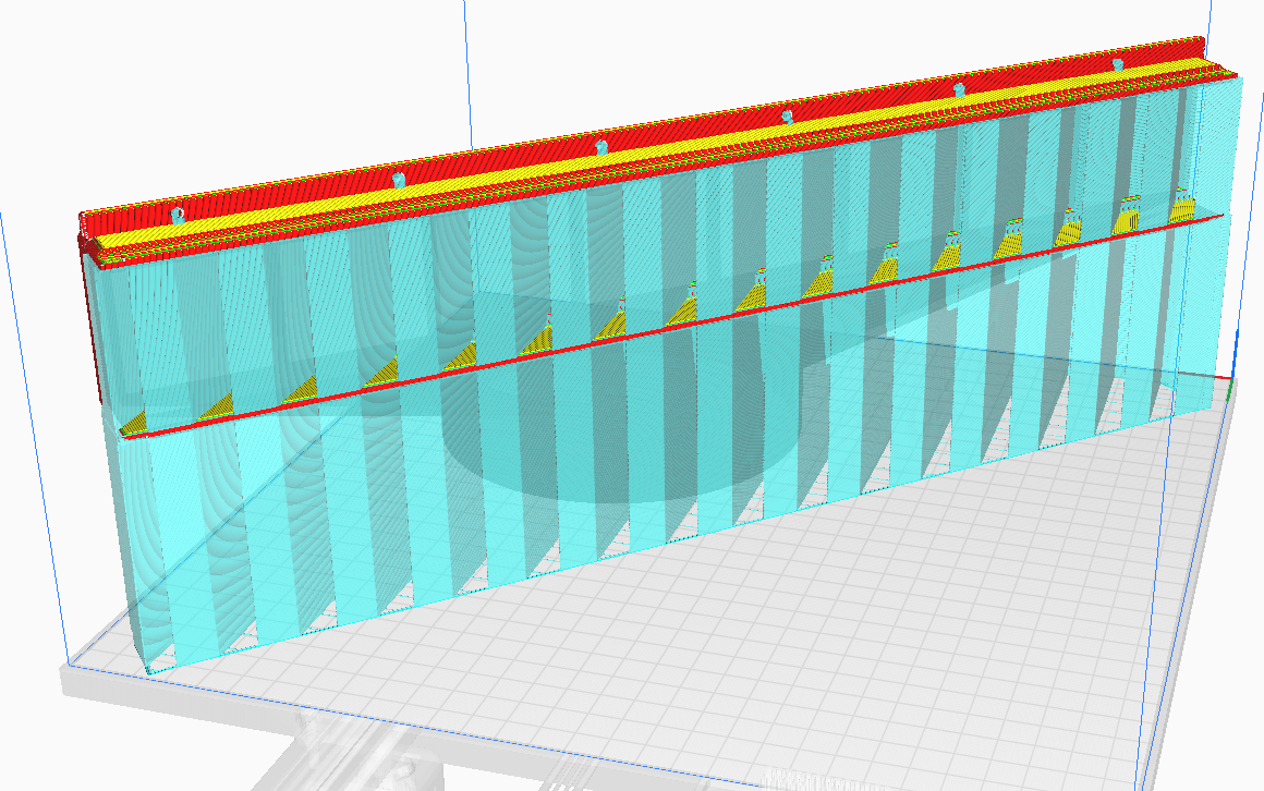
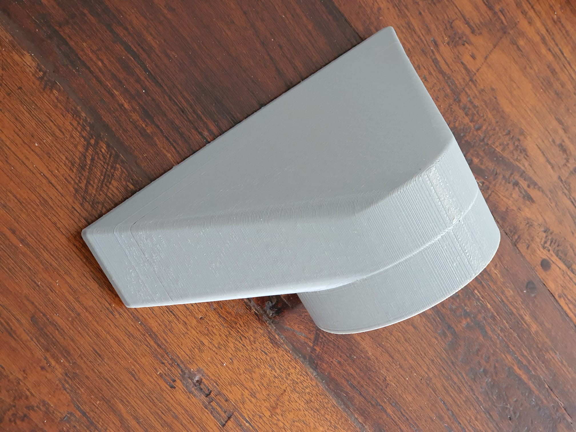
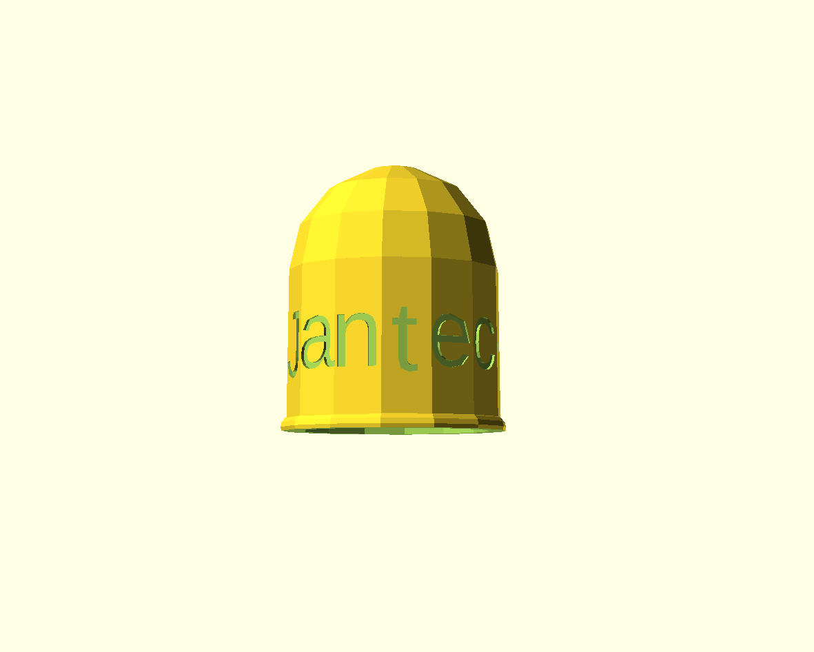
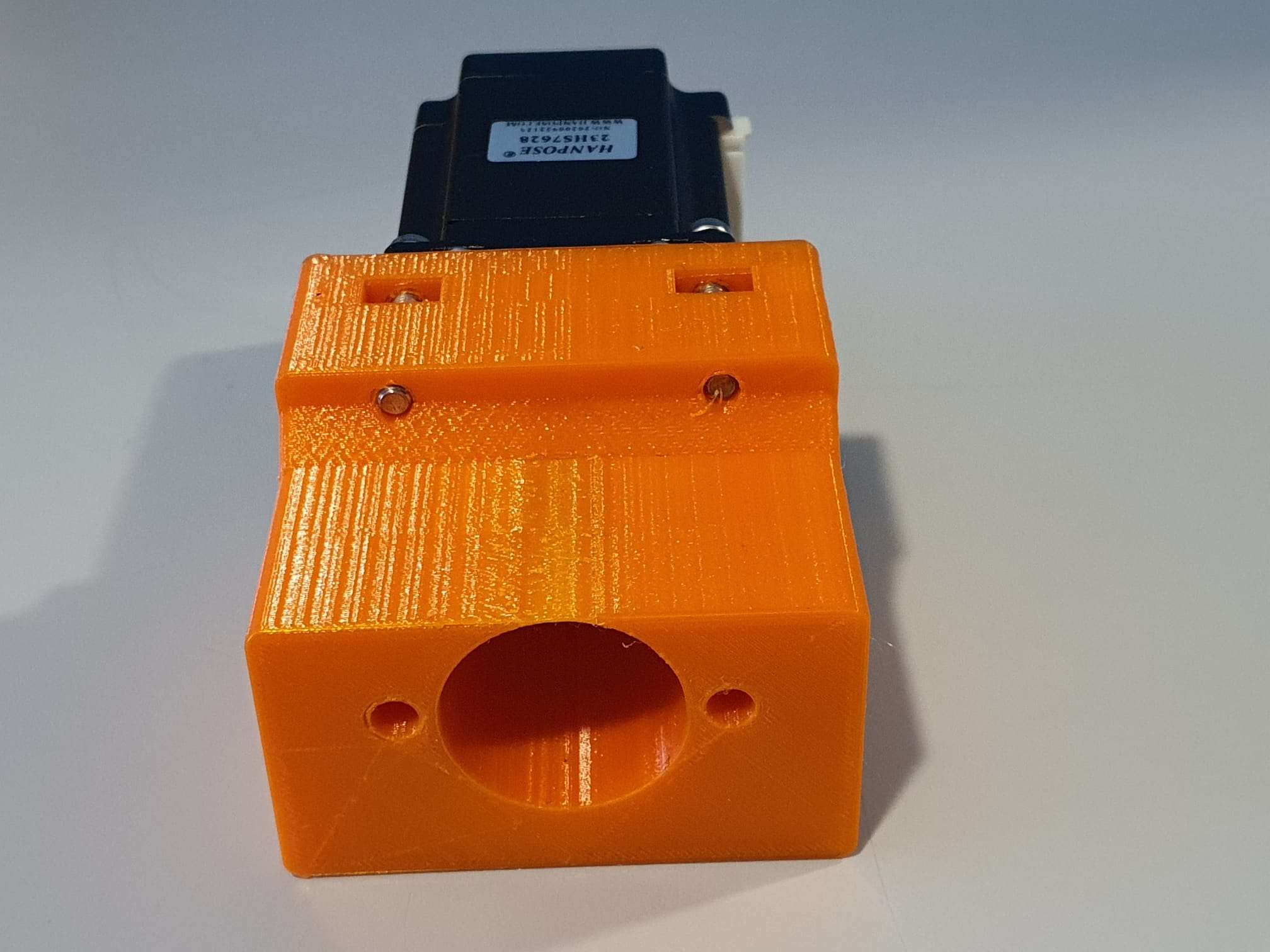
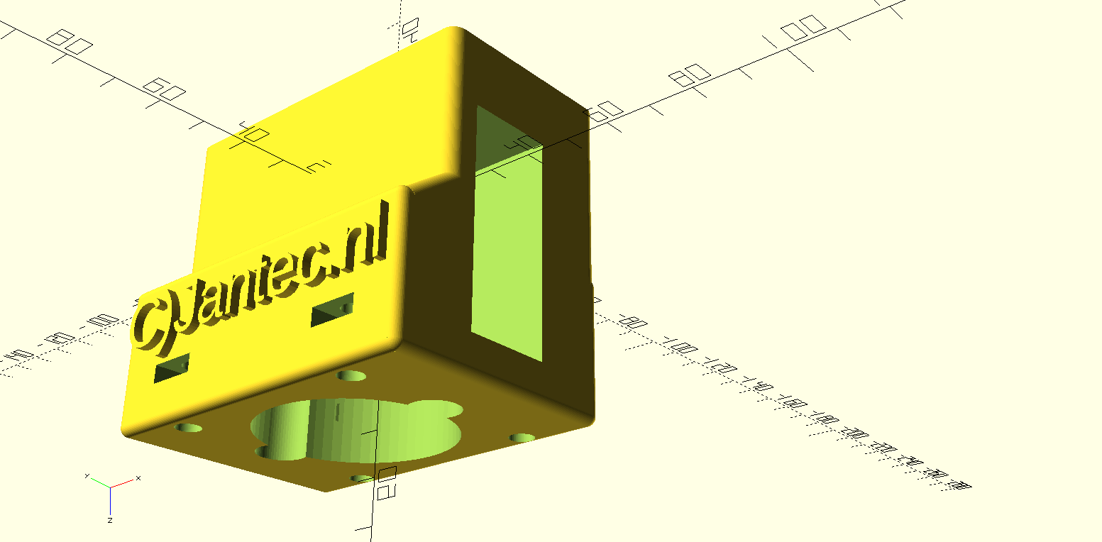
One STL is for the rear and includes the Nano box, the other is for the front face of the clock. Position the rear STL 180 degrees (so up goes down) in your slicer, so both the box and the LED housing are at Z-0 level, i.e. facing down at the same horizontal level. The front can best be printed with the flat side down. ABS is not recommended since it has less stiffness, but will probably also work. For me PETG or PLA works best.
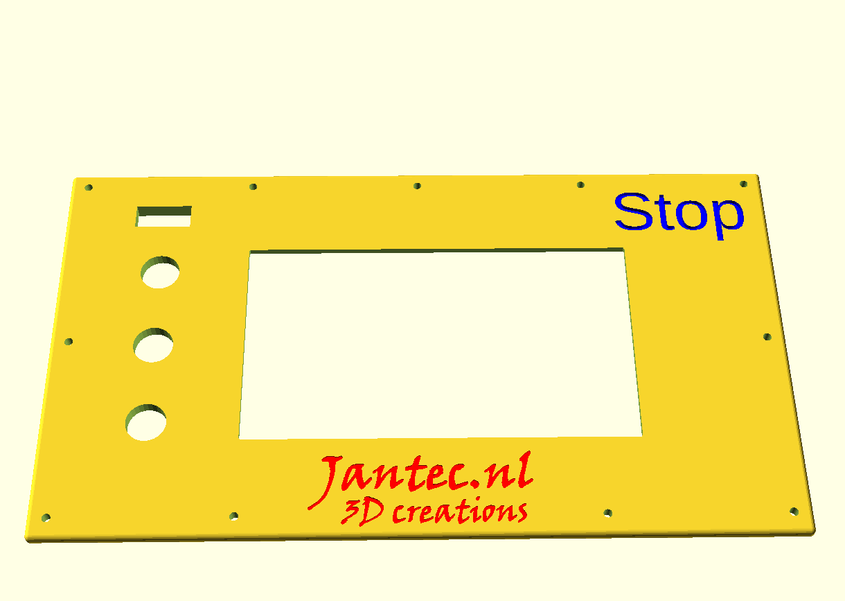
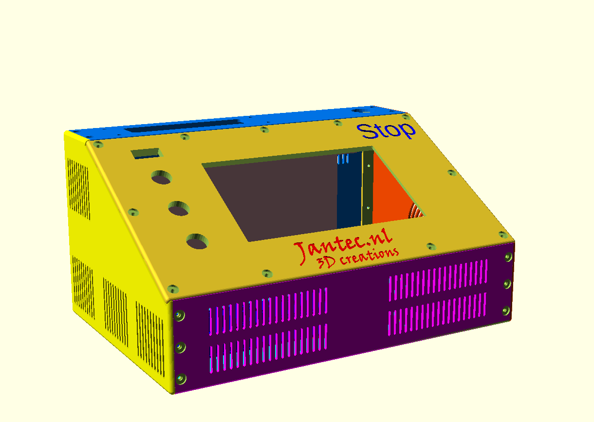
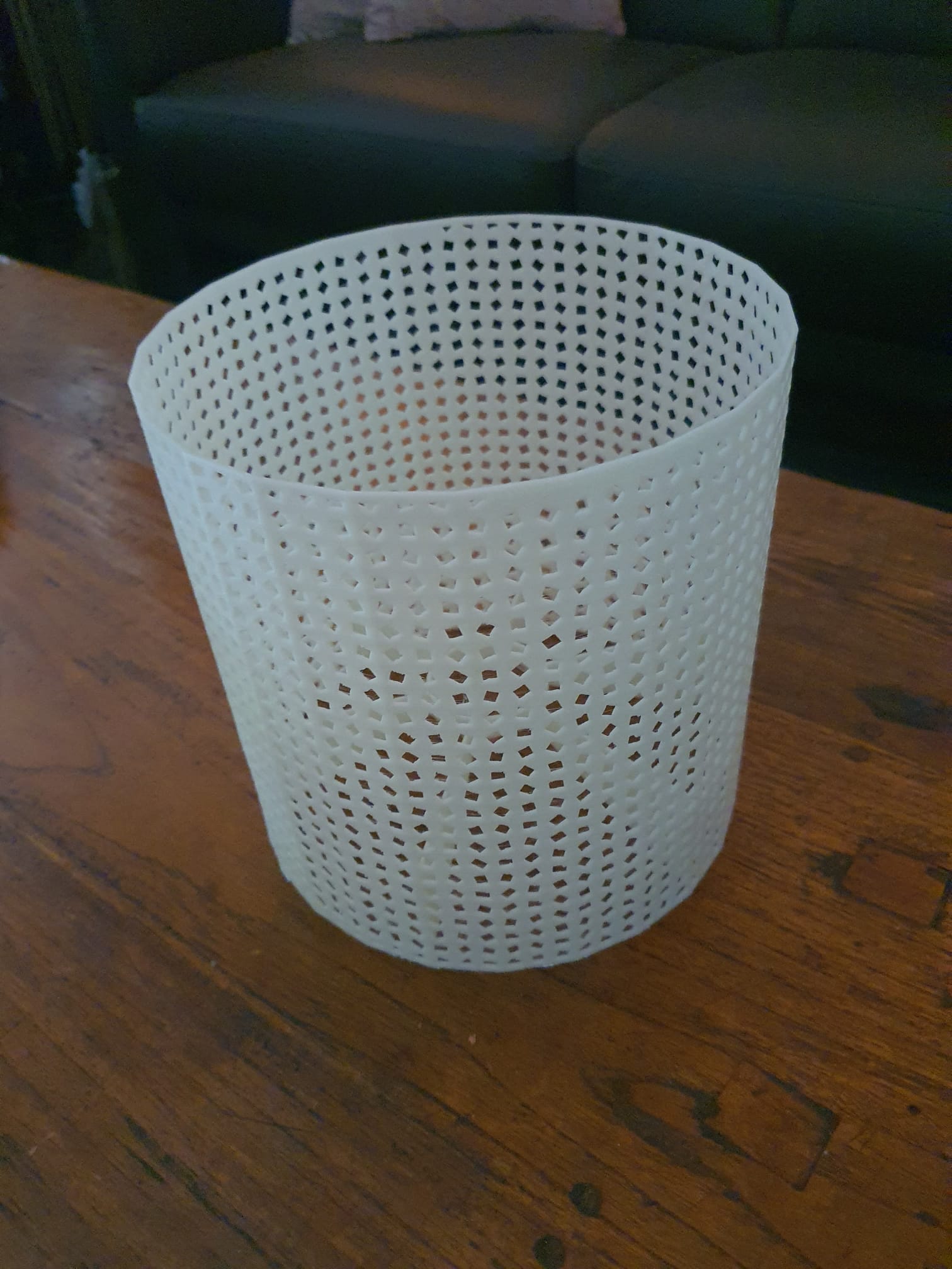
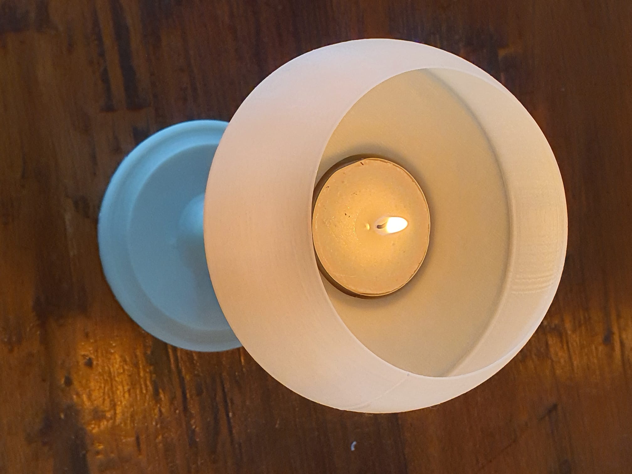
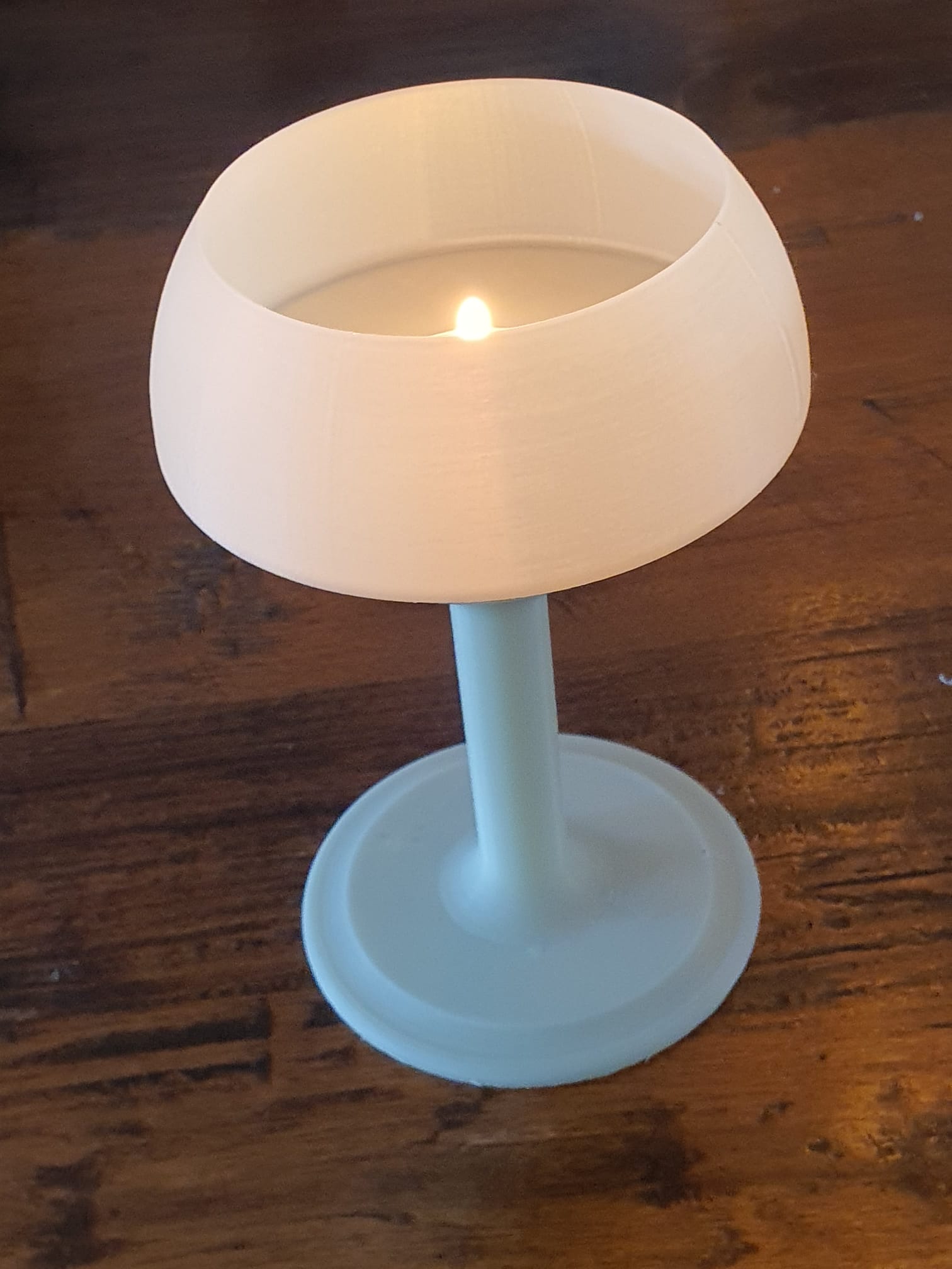
Use white filament for the front part, the rear can be any color you like.
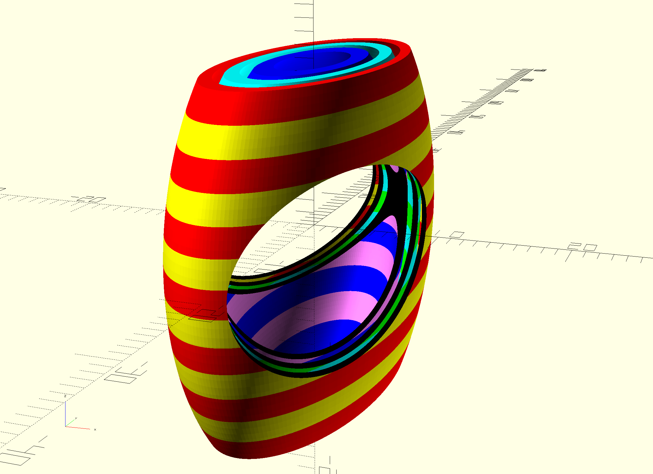
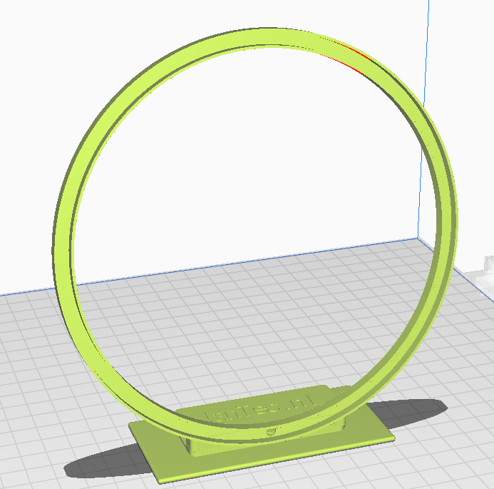
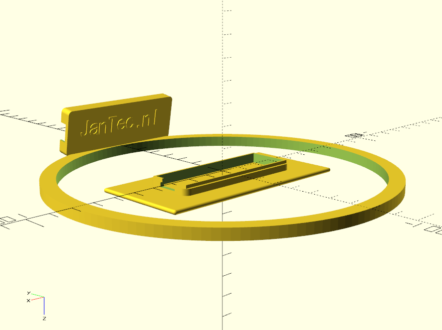
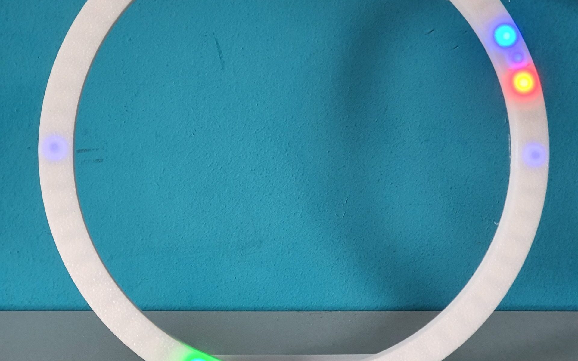
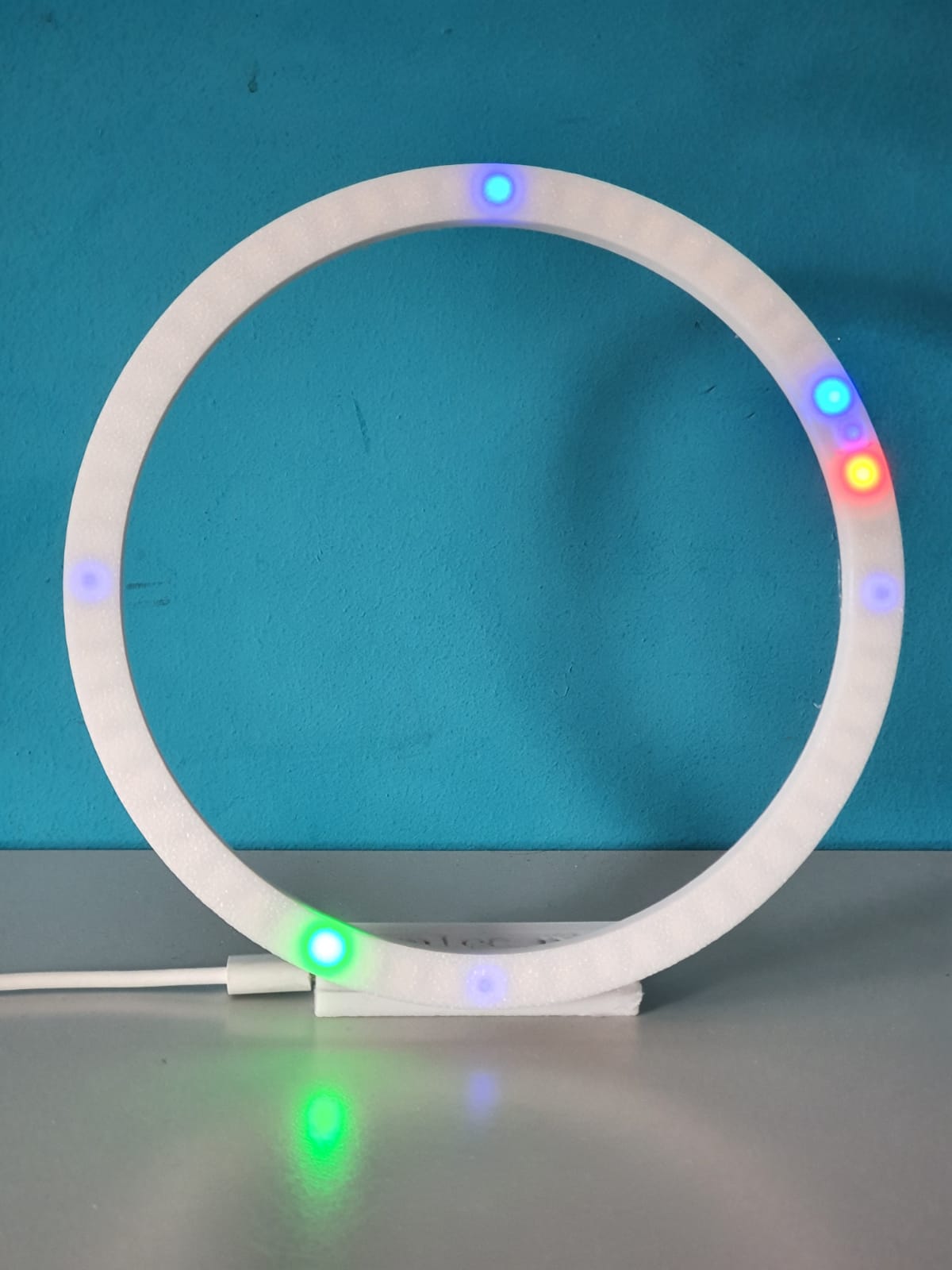
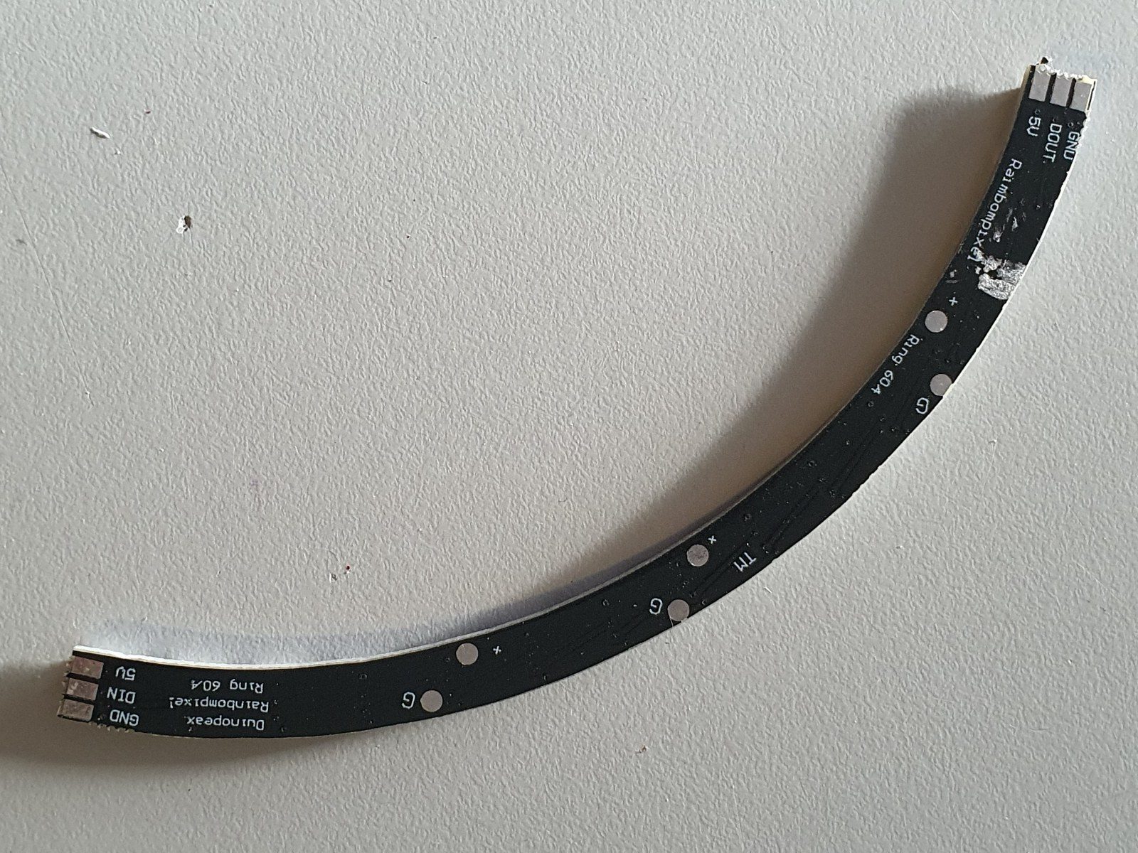
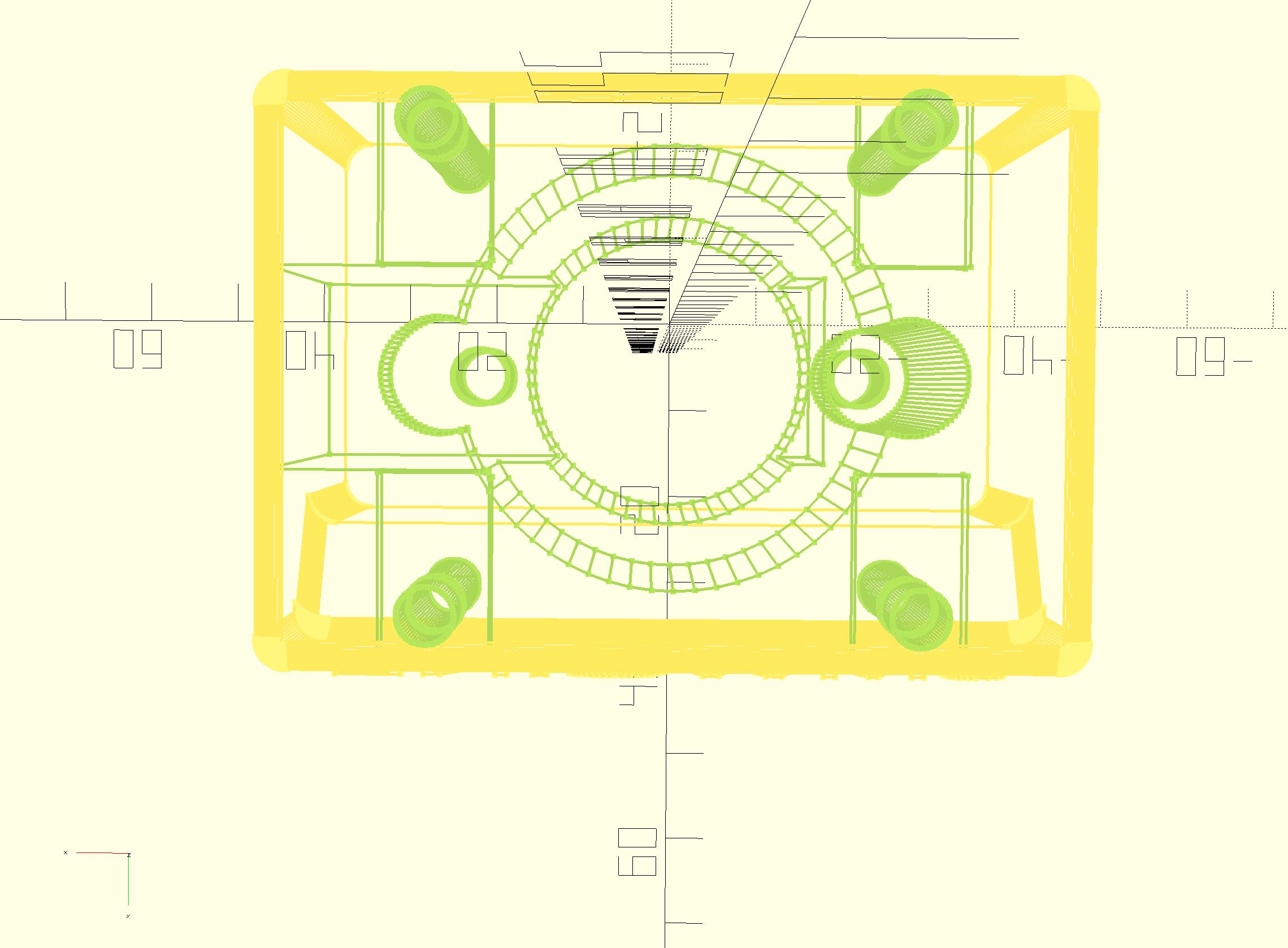
In the circle the 4 WS2812 LED segments are positioned in 1 full circle of about 160mm.
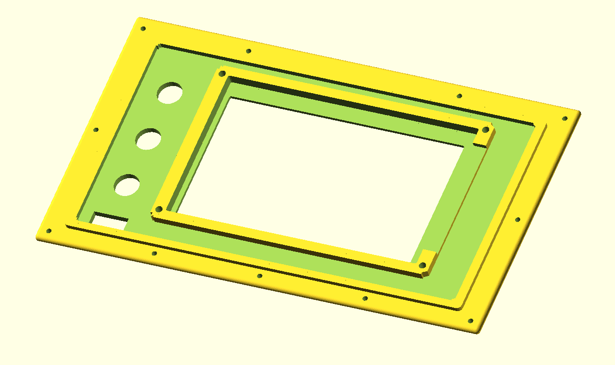
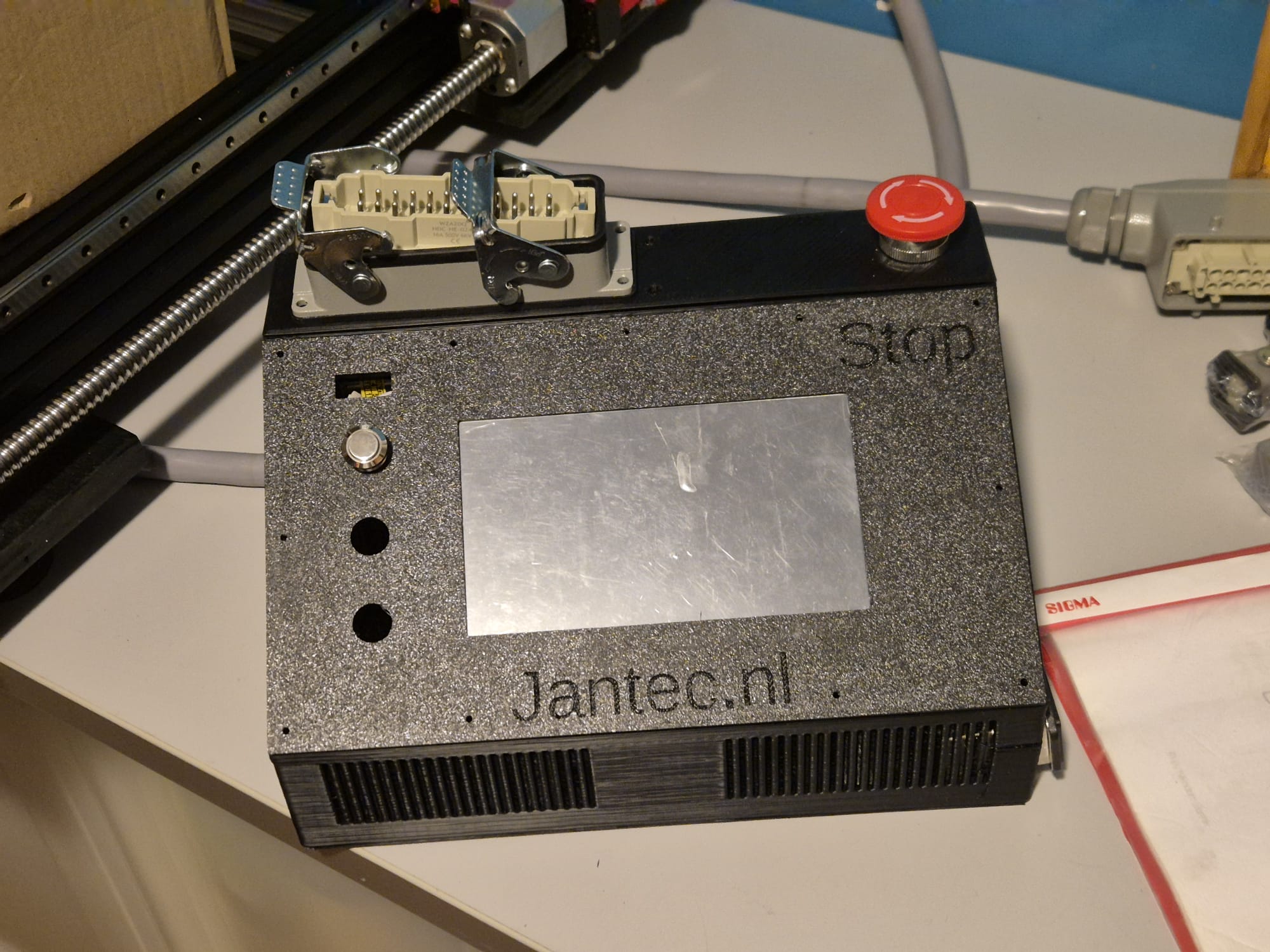
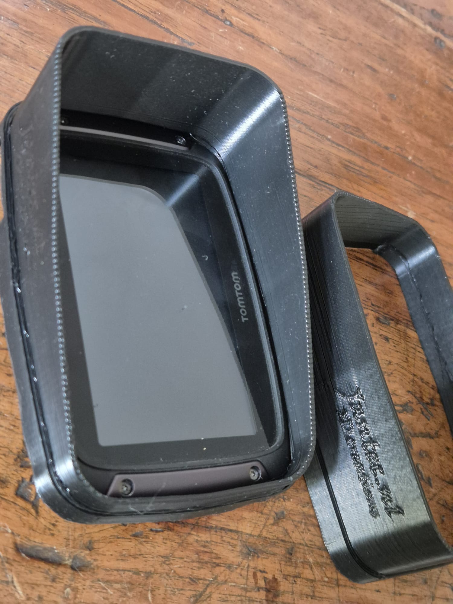
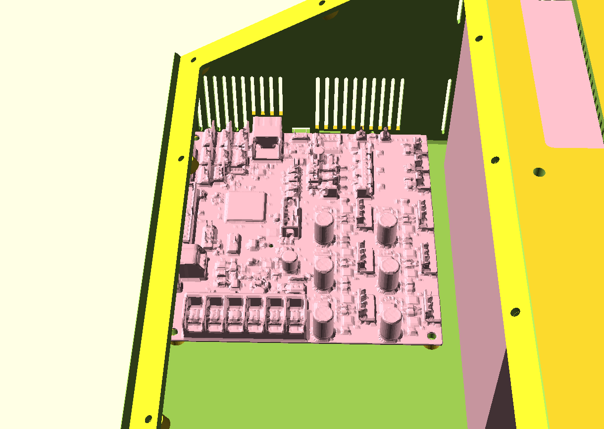
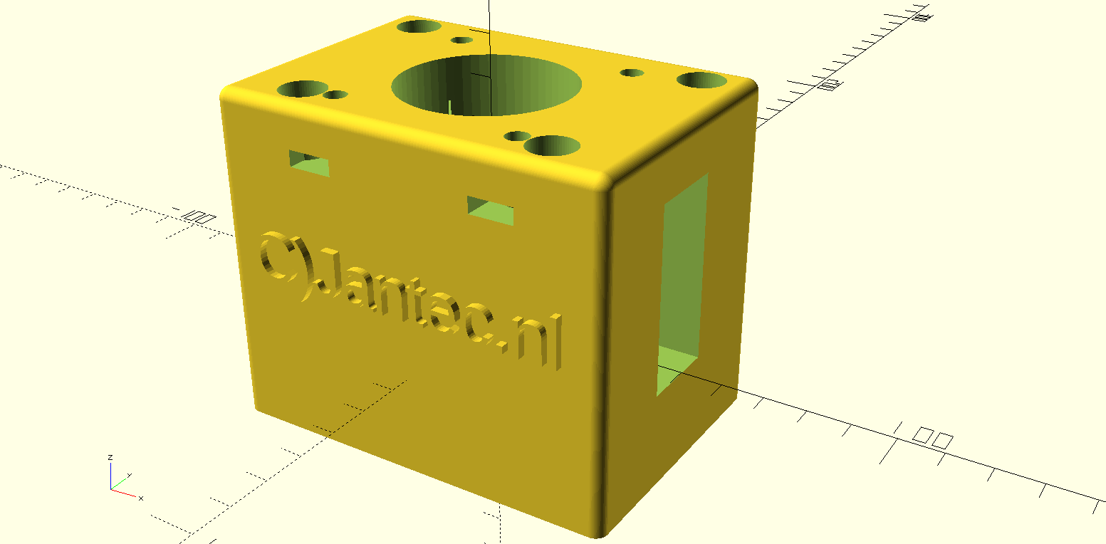
Once you have the rear electronics connected, the front will slide snug over it. No glue required. But the LED ring can best be glued in 4 places with a drop of hotglue to the base of the rear housing. Best to do this after you are sure everything works OK.
The LED parts are available on a.o. banggood , aliexpress and so on, search for 60LED circle WS2812 that has the 160 mm outer diameter.
Each LED represents a dot either for seconds, minutes or as hour indicator.
The colors detemine the function. Blue is also used as Quarter indicator with less intensity, to have a feeling of positioning for the other LEDS when it is dark.
Please look at the video above of the ‘open’ demo model to understand how it works.
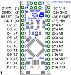
Below you can find the Arduino code for the used Nano3, as-is. it works for me, and in the code you will also find all required electrical connections and the used Time module’s spec.
When connected to your PC, you can program the Arduino and via the serial interface you can afterwards change special settings of the clock like brightness, special quarter dimlit indicators, et cetera. it’s all in the code below.
The controls can be sent via a serial interface with the usb input of the Arduino, via a terminalprogram like YAT or with the Arduino IDE program’s interface.
The commands are:
- f; fader OFF
- F; fader ON
- m (number); dim the 4 blue marker LED’s with value (number)
- S; sync to RTC time
- s; sync to System time (computer)
- t (time); change system time to:
- b; brightness of all non-marker LEDs
Please donate $1 to my paypal account if you use (parts of) my developed materials so I can continue to share nice stuff for you to download
Hope you will have a good build!
Cheers,
jan

The Arduino code, to be used for programming the Arduino Nano3 is available at the bottom of this post as plain text to be imported in an empty arduino file (with copy and paste).
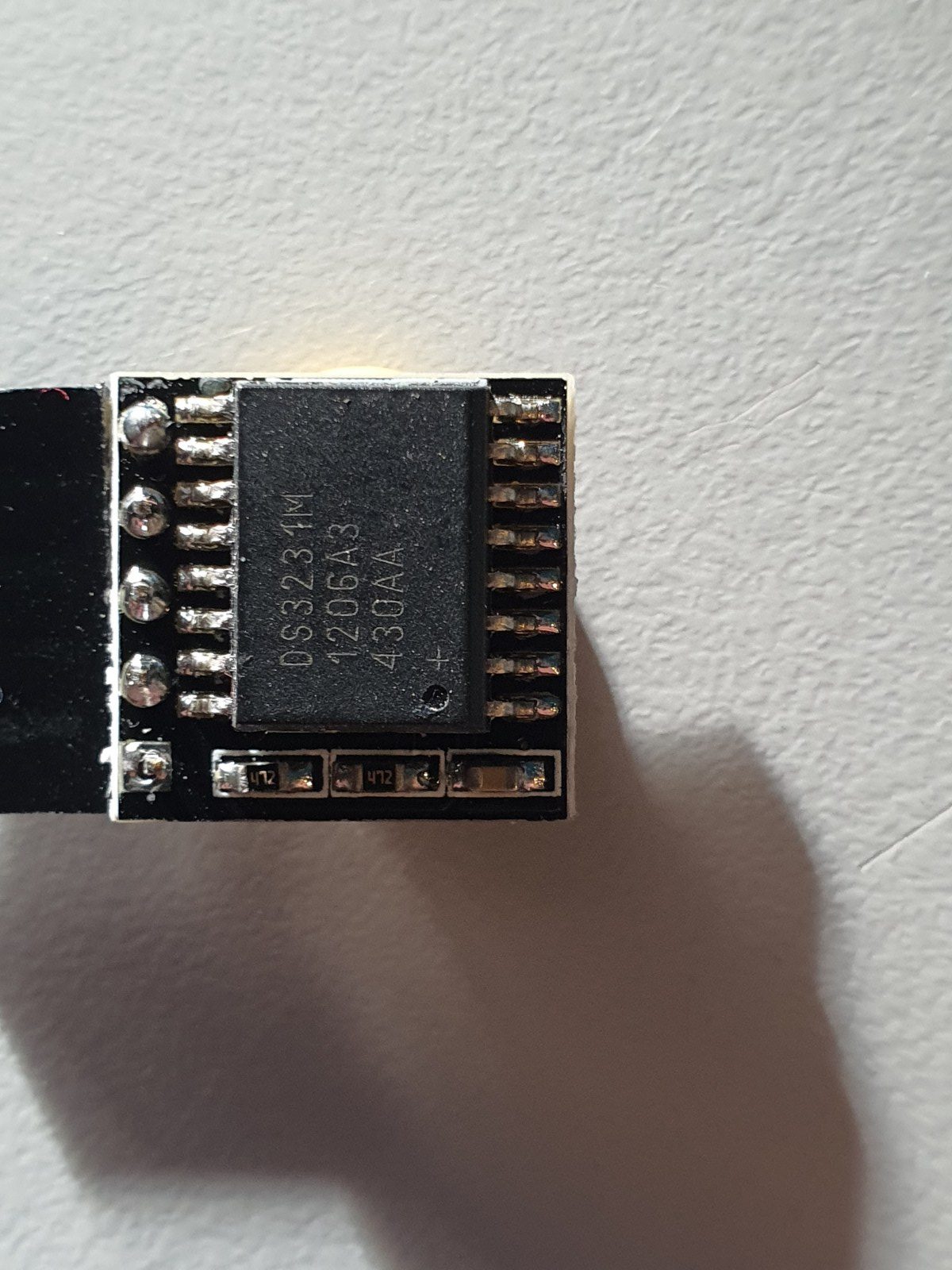
Take care to use only the libraries and time module that are specified in the code! The used time module is of the better generation that holds the time very well, also on standby.
When connecting the wires between the neopixel segments, the arduino and the time module, use a temperature-regulated soldering tool. Use a fan when you are soldering and don’t inhale the toxic gases while soldering.


The Arduino code is shown below, to be imported in Arduino in an .ino file. With Arduino, you must compile the code to get the Arduino flashed with the program. If you want to do this easier, you can make use of the binary file I already compiled for both Arduino nano versions (with full memory and with half memory). Both Arduino nano types will be OK to use for this build, but they each require specific firmware.
The last part of this post is the Arduino program for the clock:
/**
* NeoClock
*
* Clock using 60 WS2812B/Neopixel LEDs and DS3231 RTC
* Small changes and updates made by jan Griffioen, Amsterdam Europe 2018-2021
* Libraries needed:
* * Adafruit NeoPixel (Library Manager) – Phil Burgess / Paint Your Dragon for Adafruit Industries – LGPL3
* *
* * Arduino Timezone Library (https://github.com/JChristensen/Timezone) – Jack Christensen – CC-BY-SA
* * Time Library (https://github.com/PaulStoffregen/Time) – Paul Stoffregen, Michael Margolis – LGPL2.1
*/
#include <Adafruit_NeoPixel.h>
#ifdef __AVR__
#include <avr/power.h>
#endif
#if defined(ESP8266)
#include <pgmspace.h>
#else
#include <avr/pgmspace.h>
#endif
/* for software wire use below
#include <SoftwareWire.h> // must be included here so that Arduino library object file references work
#include <RtcDS3231.h>
SoftwareWire myWire(SDA, SCL);
RtcDS3231<SoftwareWire> Rtc(myWire);
for software wire use above */
/* for normal hardware wire use below */
#include <Wire.h> // must be included here so that Arduino library object file references work
#include <RtcDS3231.h>
RtcDS3231<TwoWire> Rtc(Wire);
/* for normal hardware wire use above */
#include <TimeLib.h> //http://www.arduino.cc/playground/Code/Time
#include <Timezone.h> //https://github.com/JChristensen/Timezone
#include <EEPROM.h>
//Central European Time (Frankfurt, Paris)
TimeChangeRule CEST = {“CEST”, Last, Sun, Mar, 2, 120}; //Central European Summer Time
TimeChangeRule CET = {“CET “, Last, Sun, Oct, 3, 60}; //Central European Standard Time
Timezone CE(CEST, CET);
TimeChangeRule *tcr; //pointer to the time change rule, use to get the TZ abbrev
time_t utc;
#define PIN 5
unsigned long lastMillis = millis();
byte dimmer = 0x88;
byte hmark = 0;
byte ohour=0;
byte ominute=0;
byte osecond=0;
boolean fader=true;
Adafruit_NeoPixel strip = Adafruit_NeoPixel(60, PIN, NEO_GRB + NEO_KHZ800);
void setup() {
Serial.begin(57600);
strip.begin();
strip.setBrightness(50);
// Some example procedures showing how to display to the pixels:
// colorWipe(strip.Color(255, 0, 0), 50); // Red
//colorWipe(strip.Color(0, 255, 0), 50); // Green
//colorWipe(strip.Color(0, 0, 255), 50); // Blue
//colorWipe(strip.Color(0, 0, 0, 255), 50); // White RGBW
// Send a theater pixel chase in…
//theaterChase(strip.Color(127, 127, 127), 50); // White
theaterChase(strip.Color(127, 0, 0), 50); // Red
//theaterChase(strip.Color(0, 0, 127), 50); // Blue
//rainbow(20);
rainbowCycle(2);
//theaterChaseRainbow(50);
strip.clear();
strip.show(); // Initialize all pixels to ‘off’
Rtc.Begin();
Rtc.Enable32kHzPin(false);
Rtc.SetSquareWavePin(DS3231SquareWavePin_ModeNone);
if (!Rtc.GetIsRunning())
{
Serial.println(“Rtc was not actively running, starting now”);
Rtc.SetIsRunning(true);
}
if (!Rtc.IsDateTimeValid())
{
// Common Cuases:
// 1) the battery on the device is low or even missing and the power line was disconnected
Serial.println(“Rtc lost confidence in the DateTime!”);
}
byte eechk = EEPROM.read(0);
if(eechk == 0xAA) { //Assume this is our config and not a fresh chip
dimmer = EEPROM.read(1);
hmark = EEPROM.read(2);
fader = EEPROM.read(3);
}
timeSync();
}
void calcTime(void) {
utc = now();
CE.toLocal(utc, &tcr);
ohour = hour(utc);
ominute = minute(utc);
if(osecond != second(utc)) {
osecond = second(utc);
lastMillis = millis();
if(ominute == 0 && osecond == 0) {
//Every hour
timeSync();
}
}
}
void addPixelColor(byte pixel, byte color, byte brightness) {
color *= 8;
uint32_t acolor = brightness;
acolor <<= color;
uint32_t ocolor = strip.getPixelColor(pixel);
ocolor |= acolor;
strip.setPixelColor(pixel, ocolor);
}
void drawClock(byte h, byte m, byte s) {
strip.clear();
addPixelColor(m, 1, dimmer);
if(hmark > 0) {
for(byte i = 0; i<12; i++) {
addPixelColor((5*i), 2, hmark);
}
}
h %= 12;
h *= 5;
h += (m/12);
addPixelColor(h, 2, dimmer);
// 0x RR GG BB
if(fader) {
byte dim_s1 = dimmer;
byte dim_s2 = 0;
byte px_s2 = s+1;
if(px_s2 >= 60) px_s2 = 0;
unsigned long curMillis = millis()-lastMillis;
if(curMillis < 250) {
dim_s2 = 0;
dim_s1 = dimmer;
}else{
dim_s2 = map(curMillis, 250, 1000, 0, dimmer);
dim_s1 = dimmer – map(curMillis, 250, 1000, 0, dimmer);
}
// Add blue low intensity dots for 12(0),3, 6 and 9 O’çlock to verify where the clock is positioned..
addPixelColor(15, 128, 10);
addPixelColor(30, 128, 10);
addPixelColor(45, 128, 10);
addPixelColor(0, 128, 40);
addPixelColor(s, 0, dim_s1);
addPixelColor(px_s2, 0, dim_s2);
}else{
addPixelColor(s, 0, dimmer);
}
// add a background color
// setBrightness(Serial.parseInt());
// uint16_t j;
// for(j=0; j<60; j++) { // 1 cycles of colors on wheel
// strip.setPixelColor(j, Wheel(((j * 256 / strip.numPixels()) + j) & 255));
// }
strip.show();
}
byte rounds = 0;
void loop() {
calcTime();
if(rounds++ > 100) {
Serial.print(ohour);
Serial.print(“:”);
Serial.print(ominute);
Serial.print(“:”);
Serial.print(osecond);
Serial.println(“(C)JG-2020”);
rounds = 0;
}
//rainbow(21);
if (osecond == 59){theaterChase(strip.Color(0, 0, 127), 40); }// Blue; }
//if (ominute == 59 AND osecond == 59){theaterChase(strip.Color(0, 127, 0), 50); }// Green}
//if (ohour == 11 AND ominute == 59 AND osecond == 59){theaterChase(strip.Color(127, 127, 0), 50); }// Green}
else {drawClock(ohour,ominute,osecond);}
delay(10);
chkSer();
}
void timeSync(void) {
RtcDateTime dt = Rtc.GetDateTime();
setTime(dt.Hour(),dt.Minute(),dt.Second(),dt.Day(),dt.Month(),dt.Year());
Serial.print(“Synced to: “);
Serial.print(dt.Year());
Serial.print(“-“);
Serial.print(dt.Month());
Serial.print(“-“);
Serial.print(dt.Day());
Serial.print(“-“);
Serial.print(dt.Hour());
Serial.print(“-“);
Serial.print(dt.Minute());
Serial.print(“-“);
Serial.println(dt.Second());
}
void timeSave(void) {
utc = now();
RtcDateTime store = RtcDateTime(year(utc), month(utc), day(utc), hour(utc), minute(utc), second(utc));
Rtc.SetDateTime(store);
Serial.print(“Synced to: “);
Serial.print(year(utc));
Serial.print(“-“);
Serial.print(month(utc));
Serial.print(“-“);
Serial.print(day(utc));
Serial.print(“-“);
Serial.print(hour(utc));
Serial.print(“-“);
Serial.print(minute(utc));
Serial.print(“-“);
Serial.println(second(utc));
}
void setBrightness(byte brightness) {
dimmer = brightness;
}
void chkSer(void) {
unsigned int iy;
byte im,id,iH,iM,iS;
if(!Serial.available()) return;
switch(Serial.read()) {
case ‘b’:
setBrightness(Serial.parseInt());
Serial.print(F(“Brightness changed to: “));
Serial.println(dimmer);
EEPROM.put(0, 0xAA);
EEPROM.put(1, dimmer);
break;
case ‘t’:
iy = Serial.parseInt();
im = Serial.parseInt();
id = Serial.parseInt();
iH = Serial.parseInt();
iM = Serial.parseInt();
iS = Serial.parseInt();
setTime(iH,iM,iS,id,im,iy);
Serial.println(F(“System time changed”));
break;
case ‘f’:
fader = false;
EEPROM.put(0, 0xAA);
EEPROM.put(3, 0);
Serial.println(F(“Fader off”));
break;
case ‘F’:
fader = true;
EEPROM.put(0, 0xAA);
EEPROM.put(3, 1);
Serial.println(F(“Fader on”));
break;
case ‘m’:
hmark = Serial.parseInt();
EEPROM.put(0, 0xAA);
EEPROM.put(2, hmark);
Serial.println(F(“HMark changed”));
break;
case ‘s’:
timeSync();
Serial.println(F(“Synced RTC to System”));
break;
case ‘S’:
timeSave();
Serial.println(F(“Synced System to RTC”));
break;
default:
Serial.println(‘?’);
}
}
// Fill the dots one after the other with a color
void colorWipe(uint32_t c, uint8_t wait) {
for(uint16_t i=0; i<strip.numPixels(); i++) {
strip.setPixelColor(i, c);
strip.show();
delay(wait);
}
}
void rainbow(uint8_t wait) {
uint16_t i, j;
for(j=0; j<256; j++) {
for(i=0; i<strip.numPixels(); i++) {
strip.setPixelColor(i, Wheel((i+j) & 25));//255
}
strip.show();
delay(wait);
}
}
// Slightly different, this makes the rainbow equally distributed throughout
void rainbowCycle(uint8_t wait) {
uint16_t i, j;
for(j=0; j<256*5; j++) { // 5 cycles of all colors on wheel
for(i=0; i< strip.numPixels(); i++) {
strip.setPixelColor(i, Wheel(((i * 256 / strip.numPixels()) + j) & 255));
}
strip.show();
delay(wait);
}
}
//Theatre-style crawling lights.
void theaterChase(uint32_t c, uint8_t wait) {
for (int j=0; j<4; j++) { //do 4 cycles of chasing
for (int q=0; q < 3; q++) {
for (uint16_t i=0; i < strip.numPixels(); i=i+3) {
strip.setPixelColor(i+q, c); //turn every third pixel on
}
strip.show();
delay(wait);
for (uint16_t i=0; i < strip.numPixels(); i=i+3) {
strip.setPixelColor(i+q, 0); //turn every third pixel off
}
}
}
}
//Theatre-style crawling lights with rainbow effect
void theaterChaseRainbow(uint8_t wait) {
for (int j=0; j < 256; j++) { // cycle all 256 colors in the wheel
for (int q=0; q < 3; q++) {
for (uint16_t i=0; i < strip.numPixels(); i=i+3) {
strip.setPixelColor(i+q, Wheel( (i+j) % 255)); //turn every third pixel on
}
strip.show();
delay(wait);
for (uint16_t i=0; i < strip.numPixels(); i=i+3) {
strip.setPixelColor(i+q, 0); //turn every third pixel off
}
}
}
}
// Input a value 0 to 255 to get a color value.
// The colours are a transition r – g – b – back to r.
uint32_t Wheel(byte WheelPos) {
WheelPos = 255 – WheelPos;
if(WheelPos < 85) {
return strip.Color(255 – WheelPos * 3, 0, WheelPos * 3);
}
if(WheelPos < 170) {
WheelPos -= 85;
return strip.Color(0, WheelPos * 3, 255 – WheelPos * 3);
}
WheelPos -= 170;
return strip.Color(WheelPos * 3, 255 – WheelPos * 3, 0);
}