
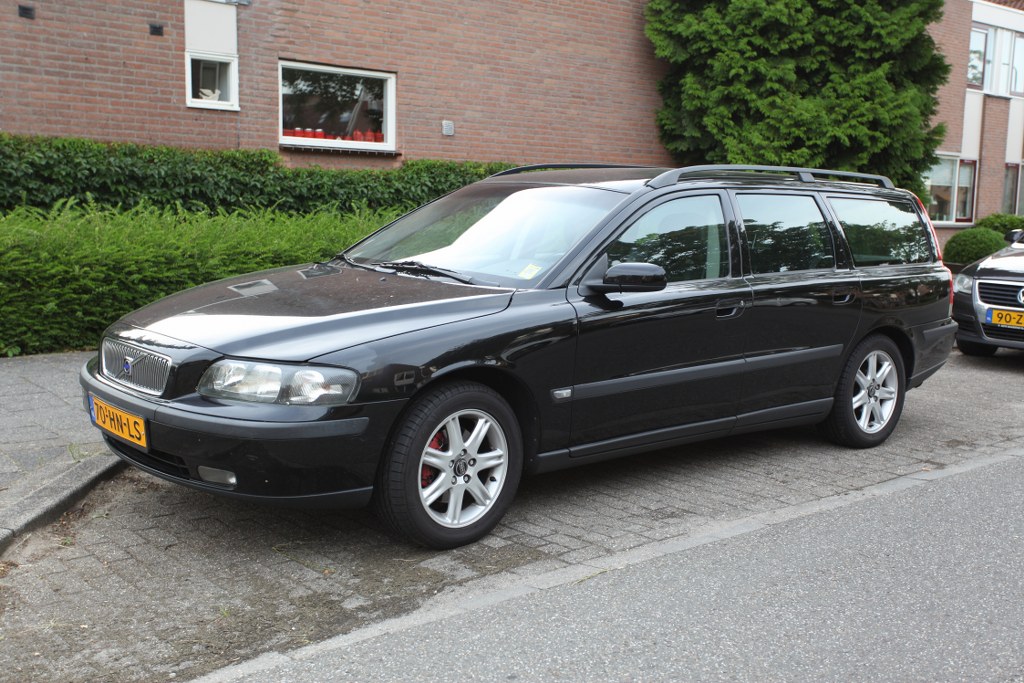
Deze is te koop, helemaal compleet voor Eur 150,= inclusief navigatie en radio


3D modeling, scanning and printing
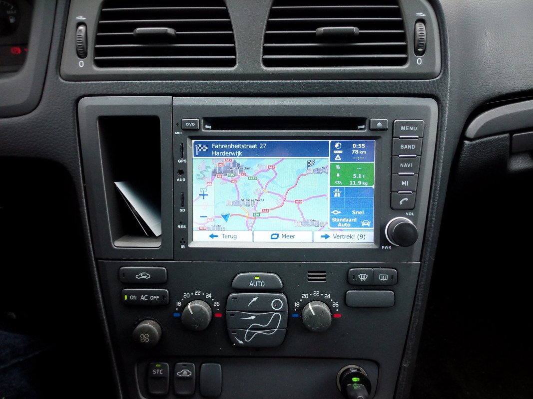
Deze is te koop, helemaal compleet voor Eur 150,= inclusief navigatie en radio
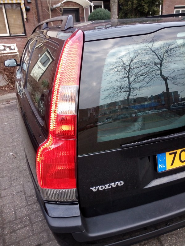
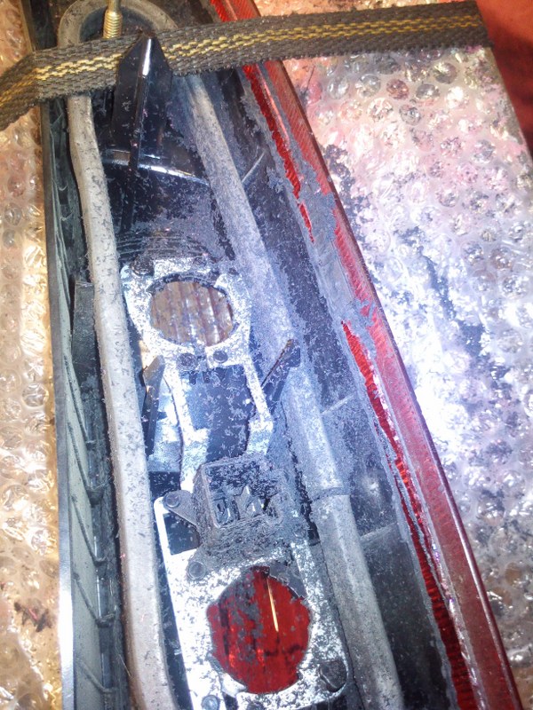
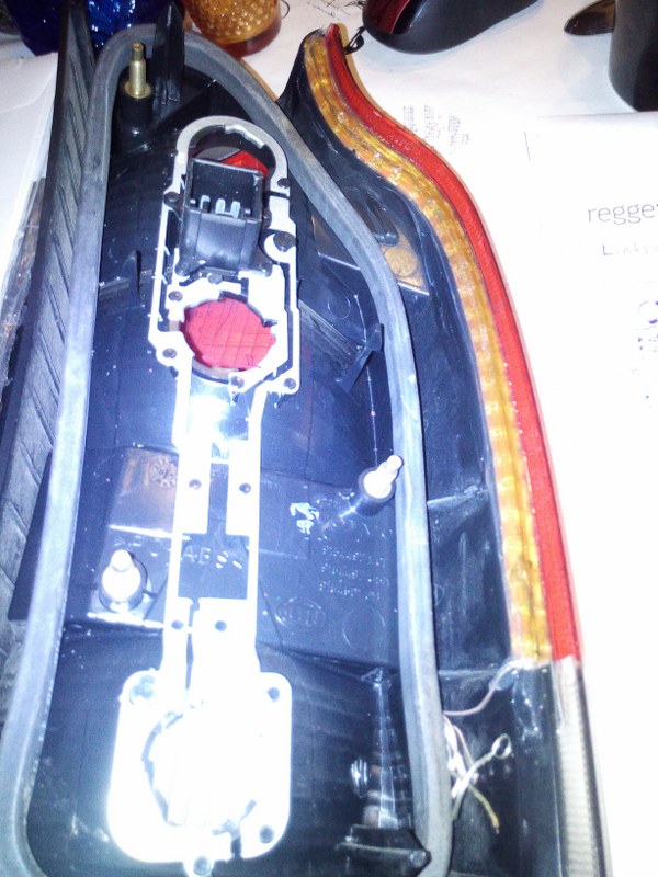
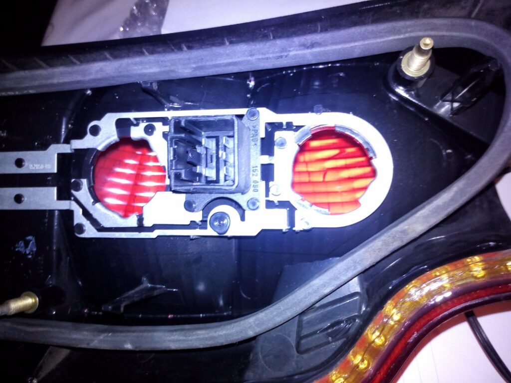
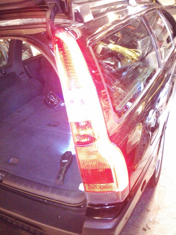
Dat vond ik altijd al zo’n mooi gezicht: De hele achterkant van de rode achterlichten met LED’s maken, en aansluiten op de reguliere verlichting. Met veel frezen en heel veel afval heb ik dit met flexibele 12 Volt led strips uitgevoerd:
Na het vervangen van de cilinderkop met de lekke klep heb ik de timing van de distributie opnieuw gesteld.
Omdat de tandwielen van de nokkenas eraf waren geweest was dit nog wel een aardig meetklusje. Daar heb ik ook speciaal gereedschap voor gekocht, om de nokkenassen te borgen aan de andere kant van de distributie.
De seals van de nokkenas zijn uiteraard ook vervangen.
Een Engelstalige beschrijving voor het stellen van de distributie heb ik als 2 downloads toegevoegd, maar je kan ook heel veel hierover vinden op Youtube!
Voor het vervangen van de distributiesnaar, en eventueel vervangen van de waterpomp en spanrollen kun je het best even op Youtube kijken, dat is eigenlijk niet zo’n ingewikkelde klus MITS je de notch van je krukastandwiel even met een witte marker aanstipt aan de voorkant/bovenkant EN je dat ook doet met je CVVT nokkenastandwielen in de positie waarin alles MOET blijven staan.
Mijn ervaring met dit type motor met CVVT is dat de tandwielen altijd verschuiven en soms de nokkenas ook.
DUS: Gebruik opspan/blokkeer gereedschap, desnoods klem je er een kurk tussenin bij de nokkenastandwielen maar zonder deze te blokkeren kun je het gemakkelijk fout doen! Het blokkeren van de krukas ligt iets moeilijker maar je kan de nokkenassen ook blokkeren met het speciale Volvo gereedschap dat aan de acherkant van de nokkenassen kan worden ingespannen, nadat je de nokkenassensors hebt verwijderd.
DOWNLOADS:
Procedure for aligning CVVT on inlet
V70 CVVT(‘s) afstellen na verwijderen van de HUB van de as, ivm geen nok of stelpunt op de interne HUB aanwezig…
With the cams locked, and the crank set on its mark, the hubs need to be rotated ClockWise as far as they will go and then have the timing marks on the gears align on the reference point (on the cover)
It would appear that the best was to do this is as follows: ( a lot of these steps are similar to replacing a timing belt, and its probably not a bad idea to do this at the same time)
Jack up the car and put it on stands, (this doesnt need to be the 1st step, but it gets everything off the ground which makes it easier to work on)
Remove the engine cross brace, I like to do this by removing the 14mm bolts that attach the brace mounts to the shock towers, and the bolt that goes through the engine mount.
Remove the Air Box and MAF, if you have a Snabb intake you may wish to remove the 1st silicone coupler to give more room.
Cover the open intake with something to prevent ingress of debris. A latex glove works great for this.
Remove the upper engine mount. (you may need to remove the OTE pipe and Coil cover to access the engine mount bolts)
Remove the timing covers. (front and top) Front is a 10mm that is a bit tricky to reach, top is T30
Remove the RHF wheel. ( if you didnt jack up the car before, now would be a good time )
Remove the nut that hold the wheel well liner on in front of the strut, fold the liner along the crease and use some vise grips to hold it in place. (FCP’s S60 timing belt change video shows this very well)
Now you will have access to the crank/harmonic balancer.
using the 30mm nut rotate the engine ClockWise until the timing marks align on the cams. (this step is not crucial, but good to confirm everything is as it should be)
Confirm that the timing marks align on the crank. (this is rather tricky to see with the harmonic balancer, serp belt and timing belt tensioner in place.)
There is 2 sets of marks on the crank, there is the notches, which should straddle the mark on the block. and there is the mark where the Harmonic balancer attaches (in the foreground of this pic:
This picture shows the timing mark on the block and crank (not the little notches)
This is hard to see with the harmonic balancer attached, but not impossible.
Unplug and Remove the Cam Position Sensors (CPS). Intake is a T25 and EX is a T40
Remove the CPS triggers (these are the things under the CPS) These are marked as IN and EX on the back side. 10mm bolt.
As the triggers are removed the cam shaft will probably rotate a little.
Now re-rotate the crank shaft through 2 complete revolutions to re-set the cam shafts.
LOCK THE CAMS ! Using a Cam Locking Tool.
Re-rotating the engine should have re-aligned the cam shaft slots and the tool should go straight in. Other videos I have seen show people using a large flat bladed screw driver to align the cam after removing the trigger. With the engine in the car this is rather difficult and shouldn’t be necessary if you re-rotate the crank.
Do the bolts up on the cam locking rather TIGHT !
The Bolts that hold the CVVT hubs onto the cam are VERY tight ! And the Cam Locking tool works very hard to counter act these forces.
Hold a rag underneath the hubs and remove the CVVT hub plugs, (T55) Oil will flow from the hub with the plug removed.
Crack, but do not remove the hub bolt.
This is under the CVVT plug, its a T55 and is VERY tight. A breaker bar will be required. We found that a T55 Key (like an allen key) with a pipe worked well, especially as there is very little room around the exhaust hub.
Remove the timing belt. (this could be done earlier, but the belt helps to take a bit of the load of cracking the T55 bolts in the hub)
Using the lever on the tensioner you can remove the belt without a lot of trouble. (if you’re replacing the timing belt you might as well remove the tensioner)
Without removing the harmonic balancer the belt will not come off comepetely but will be out of the way enough to replace the hubs)
Remove the CVVT hubs.
With the center bolt still in the hub you can confirm the hubs are either spring loaded or not. (to my knowledge the R’s only use the floating hubs)
From the position they were in they should be able to rotate Counter Clock Wise, but not clock wise (this is assuming the bolt is still snug)
Remove the gear from the hub.
Install the gear onto the new hub so that the 8mm bolts are in the middle of the oval adjustment window.
Install the CVVT hub onto the camshaft.
Clean the locking bolt to make sure it is free of oil/grease etc.
Install the bolt but do not do it up tight, just snug.
Now rotate the gear/hub ClockWise unit it is at the Clock Wise limit. (that is the limit of the hubs movement, you can move the hub back anf forth to confirm this.)
Install the timing cover with the timing marks.
Continue to rotate the hub Clock Wise with the gear until the timing mark on the gear aligns with the timing mark on the cover. (this is very tricky to get it exact)
If you go past do not rotate the gear/hub back, but continue for another lap.
In this picture you can see the marks clearly, they are also not aligned.
This picture shows that you should only rotate the hubs Clockwise during alignment and points out the 8mm adjustment bolt.
Once the hubs are in the correct spots tighten the hub bolts to 120Nm (88ft/lbs) (this is rather difficult to achieve)
We Fount that with the PS (power steering) reservoir removed we could use an extension bar to get the head of the torque wrench close to the edge of the body and it was ok.
With the exhaust it was just not possible with the tools we had. However using the T55 key and pipe it was done up tight.
Confirm that the timing marks are still correct.
You can rotate the hubs clock wise and anti clockwise to confirm they are correct. (we had the exhaust move slightly while tightening and had to re-do it)
Make sure they are left in the most clockwise position.
Install the CVVT hub plug
Install the timing belt. (and tensioner if you replaced it)
We found the best way to do this is in the following order:
Seat belt on crank.
Keeping tension on belt feed it over the idler and around the intake gear.
Feed the belt over the exhaust gear.
Then around the water pump and finally over the tensioner (again using the tensioner arm to help get the belt on)
It is rather tricky to get a good amount of tension between the crank and the intake cam.
It might take a few goes to get it right.
It is also possible that the intake or exhaust will not line up with the teeth on the belt.
My understanding is that this is where the 8mm bolts and elongated holes in the gears are use. for Fine Adjustment
Make sure the timing marks are still correct.
Remove the cam locking tool.
Rotate the engine clock wise, do it slowly. (i’m told that valves can be bent when rotating by hand, but you not be able to continue to rotate the engine if contact is made)
After 2 rotations of the crank the marks on the cams and crank should still be aligned.
The slots in the cam shafts should also be parallel to the cam cover seam (as the cam locking tool holds them)
Reinstall the CPS triggers and CPS’
Reinstall intake and MAF and you should be good to start her up.
If all goes well put it back together, and smile !
I used a ruler to precisely align
4-tighten the T55 bolt to 120nm. This will probably cause the hub to move slightly and become misaligned.
5-with the 3 8mm slacken and the hub in the clockwise limit position, move the timing gear to realign the marks.
6-tighten the 3 8mm bolts to 10nm
7-replace the cover and tighten to 35nm
On a side note I also renewed the Orings inside the cover and the inner side of the hubs.
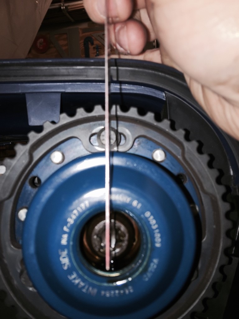
Testen met de riem erom:
Kap van motor boven, deksels distributie eraf, R voorwiel eraf, op bok aan 1 kant, schutbord opzij.
OP timing zetten op de krukas en uitlaatcam.. ]Als dit OK is, check op inlaatcam deze MOET goed zijn anders is het nodig om eerst de riem te verwijderen.
Checken doe je door aan de achterkant te checken of de as exact goed staat, dit is parallel aan de voetplaat. Al je de locjing tool aan de achterkant zou plaatsen moet hij zonder probleem passen… Check dit door de nokkenassensor en de nokkenas signaalgever van de as te verwijderen en met een lange rechte draad (laselectrode oid te meten of de as inderdaad recht staat. Bij twijfel nog een x helemaal met de klok mee de krukas draaien tot op de merktekens. Niet eroverheen, dan opnieuw ronddraaien met de klok mee! (=rechtsom)
Als de riem eraf moet, volg bovenstaande handleiding. Anders:
Als de tekens goed staan, stel dan de CVVT als volgt:
Borg de camshafts met een standaard borgingstool aan elkaar.
Verwijder aan de andere kant van de inlaatnokkenas de nokkenassensor en de nokkenas signaalgever van de as.
Maak de andere kant van de uitlaat nokkenas vrij (verwijder bovenste motorsteun, beugel, dekseltje)
Maak de afdicht torx van de CVVT los en maak de torx van de CVVT aan de as iets los, draai daarna net iets vast.
Maak de 8mm boutjes iets los en draai aan de achterkant van de inlaat nokkenas tot ze in het midden staan, maak ze vast 10nM.
Draai de inlaat nokkenas voorzichtig rechtsom met de klok MEE een hele slag tot exact de borgpositie van de assen is bereikt en zet het borggereedschap op de assen vast.
Los het borggereedschap op de poelies, laat het gereedschap aan de andere kant op de assen zitten, en maak de TORX (55)van de as vast met 120nM en de dop met 35nM
Rechecken van de timing met de 8mm boutjes en herstel is op deze manier niet meer mogelijk! Kan alleen als de riem er af is worden gechecked.
Advies is om toch de riemen te verwijderen en het Engelstalige verhaal te volgen. Niet sneller maar wel beter!
Of… riem laten zitten., torx los maar slipbaar vast zetten… op timing marks zetten van tandwielen voorzijde, as aan achterzijde 1/3 slag terug, voorwaarts draaien tot exact recht in blokkeerpositie en torx vastzetten met luchtsleutel. (eerst met makita hammersleutel op accu is ok)
Nadeel van draaien van de inlaat nokkenas vanaf de achterkant is dat hij TEGEN de normale draairichting in gaat.
Alleen al om die reden is dit niet echt aan te bevelen….
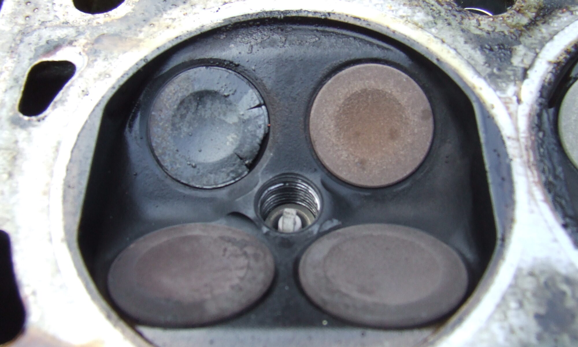
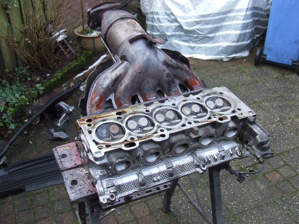
Na de vervanging van mijn cilinderkop waarvan 1 klep lekte, heb ik die kop gereviseerd. Omdat de klepzitting nog behoorlijk goed was, heb ik eerst kleppen en seals gekocht en heb ik de kleppen van de eerste cilinder ingeslepen en opnieuw geplaatst, met de veren enzovoorts. De zijdelingse speling in de klepgeleiders was eigenlijk niet meetbaar, dus ik had goede hoop op succes. Daarna een nachtje laten staan met benzine in de kom, en een afdekplaat erop. ’s Morgens geen lekkage zichtbaar langs de poorten!
Daarna alle kleppen ingeslepen, herplaatst met nieuwe klepseals en klaar!
Van mijn V70 5-cilinder met G3 LPG installatie was in 2015 bij de aankoop 1 klep verbrand, vandaar de lage prijs. ‘Het motorlampje brandt af en toe, maar dat kun je ‘resetten’ volgens de handelaar uit Harderwijk (NL). Ook lag de zijruit van het linker voorportier onderin de deur en was kennelijk een raamslider afgebroken. Maar de auto was rijdbaar dus na de aankoop heb ik ‘m rustig aan naar mijn garage gereden, achteruit geparkeerd en ben ik aan de slag gegaan.
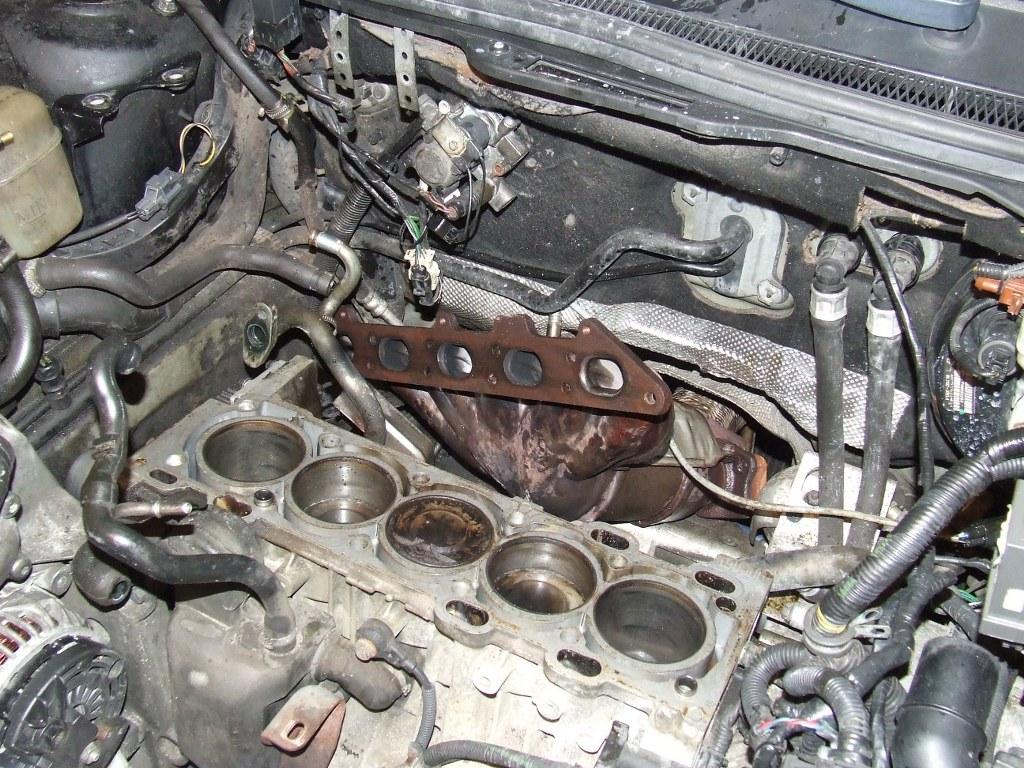
Bij aliexpress heb ik de raamsliders gekocht en de vervangingskop heb ik bij een ouderwetse Volvo-garage in het Westland voor 200 Euro op de kop getikt.
Van de vervangings cilinderkop heb ik uit voorzorg de klepsteelrubbers vervangen en gelijk alle kleppen voor de zekerheid ingeslepen.
De kop die ik van de wagen heb afgehaald heb ik later ook gereviseerd door het opzuiveren van de klepzittingen , nieuwe kleppen van de eerste cilinder en nieuwe klepseals.
En alle kleppen opnieuw ingeslepen. Die kop heb ik veel later nog verkocht via Marktplaats aan een hobbyist met hetzelfde LPG-probleem dat ik met mijn LPG-auto had.
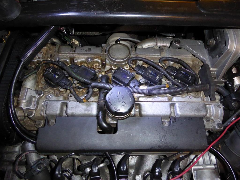
Ik heb na de kopvervanging gelijk een klepsmeersysteem gemonteerd, met een controlelampje op het dashboard wanneer de smeervloeistof op is.
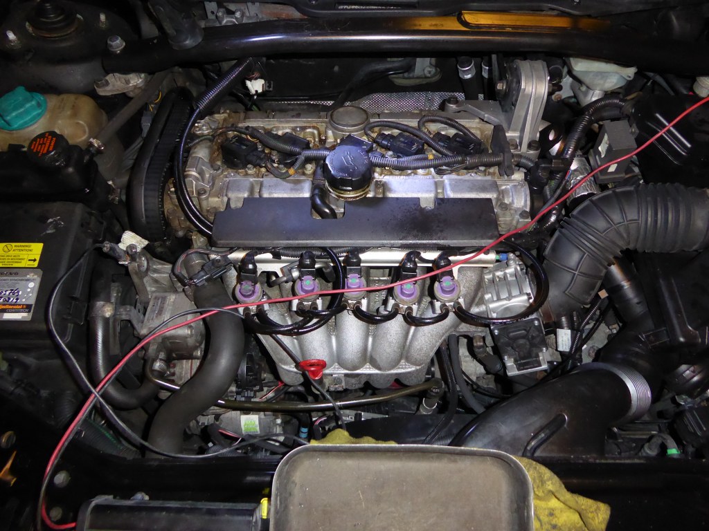
Onder vind je mijn foto’s, zonder verder commentaar maar ik denk dat alles zichzelf wijst.
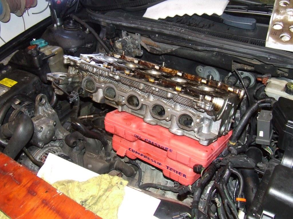
Bij het herplaatsen van de kop moet je heel goed rekening houden met de klepstoters.
De klepstoters hebben allemaal een verschillende maat (stotermaat) omdat de kleppen door het inslijten allemaal op een verschillende klepsteelhoogte uitkomen.
Daarom moet je steeds meten welke stoter waar moet worden geplaatst. De klepstoters bij mijn type auto zijn namelijk vast, en niet stelbaar.
Modernere klepstoters zijn vaak hydraulisch en zelfstellend, jammer genoeg was dat bij mijn wagen niet zo. Ik heb uiteindelijk een paar stoters geslepen om op de juiste waarde uit te komen, zie onderstaande foto’s.
Het meten kun je alleen doen door na het plaatsen en aantrekken van de kop de stoters zo goed als mogelijk te plaatsen, beginnend met 1 en dan steeds 1 meer waarbij de de nokkenassen moet monteren, aan moet drukken en dan de speling moet meten enzovoorts. Best wel een werkje maar als je handig bent is het in 2 uurtjes gedaan.
UIteindelijk heb ik deze mooie V70-II ingeruild voor een nog mooiere zilvergrijze C70 D5 automaat, 2e versie uit 2006.
Dat was een fantastische wagen, zowel het rijden als de beleving. De C70 heb ik na 2 jaar ingeruild voor een zwarte V70-III BW F (LPG-G3/ethanol/benzine) met handbak uit 2010.
Fantastisch zuinig met de 4-cilinder Ford Duratec motor, stil en comfortabel.
De C70 was nog steeds perfect maar ik kon gewoon niets en niemand meenemen, en dat brak me uiteindelijk toch op.
Ook de 160 Euro wegenbelasting per maand was voor de C70 diesel aan de hoge kant terwijl de V70-III op G3 LPG ‘maar’ 100 Euro doet aan wegenbelasting per maand.