3D printservice

Wij maken een exclusieve print van je ontwerp, op maat en supersnel!
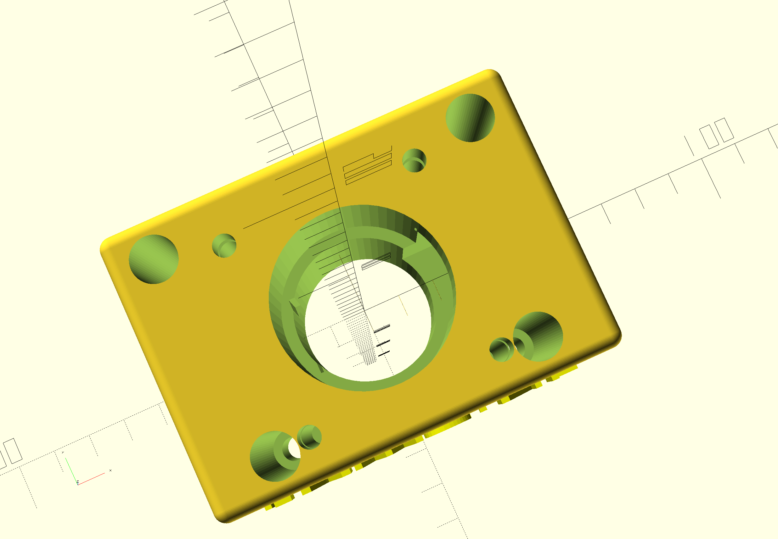
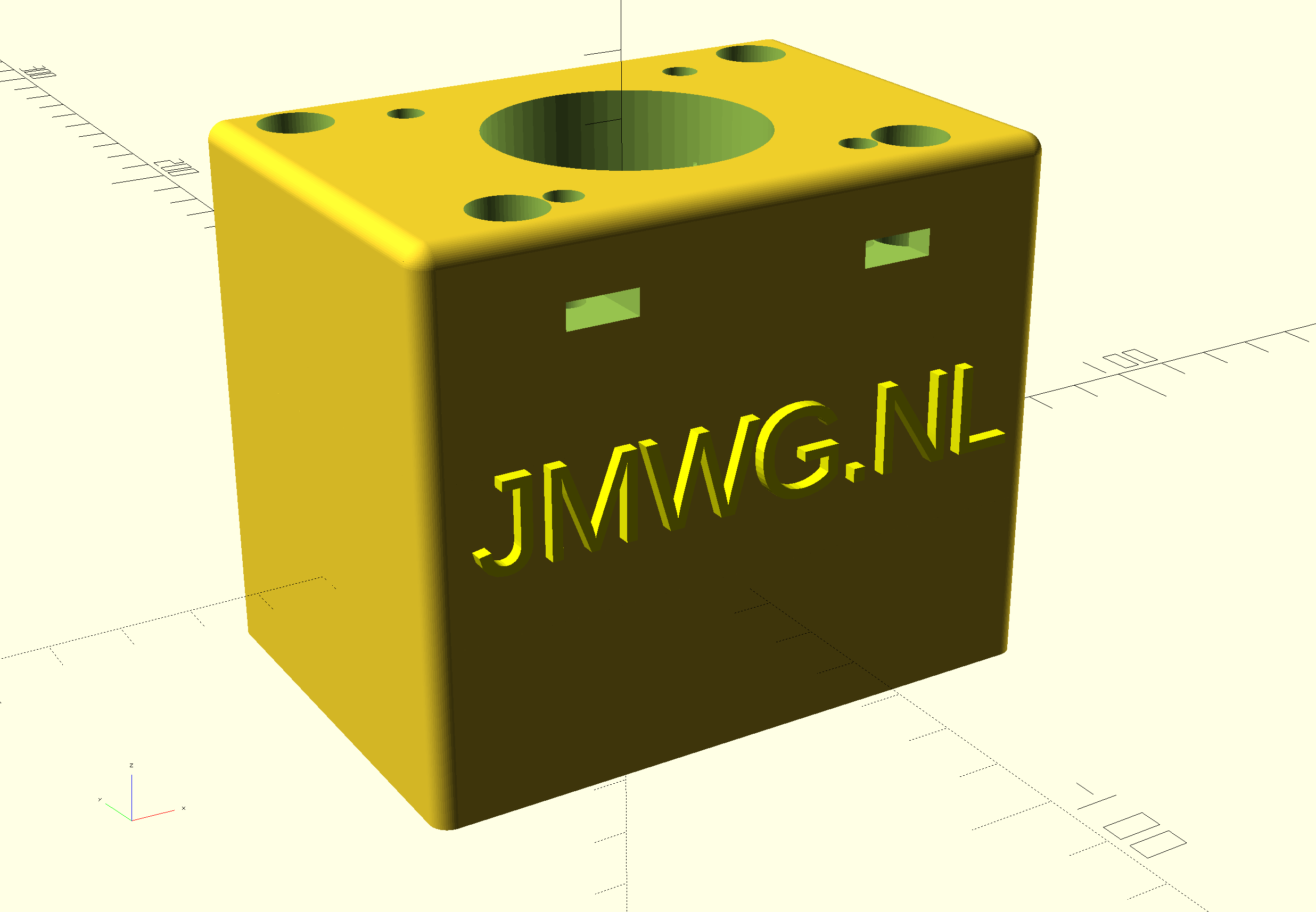
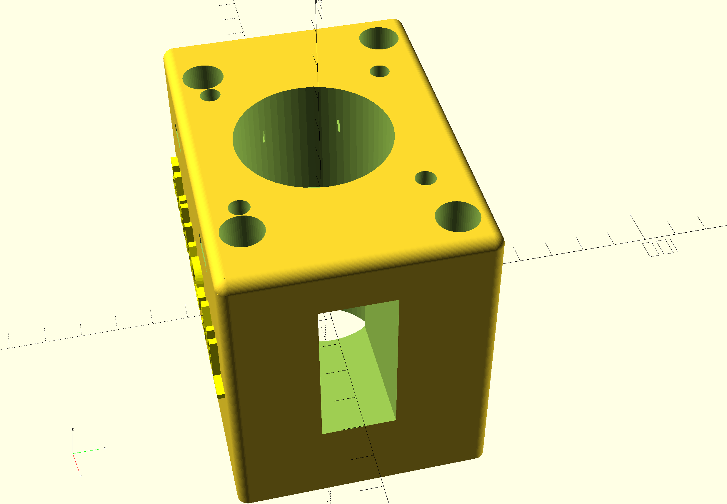
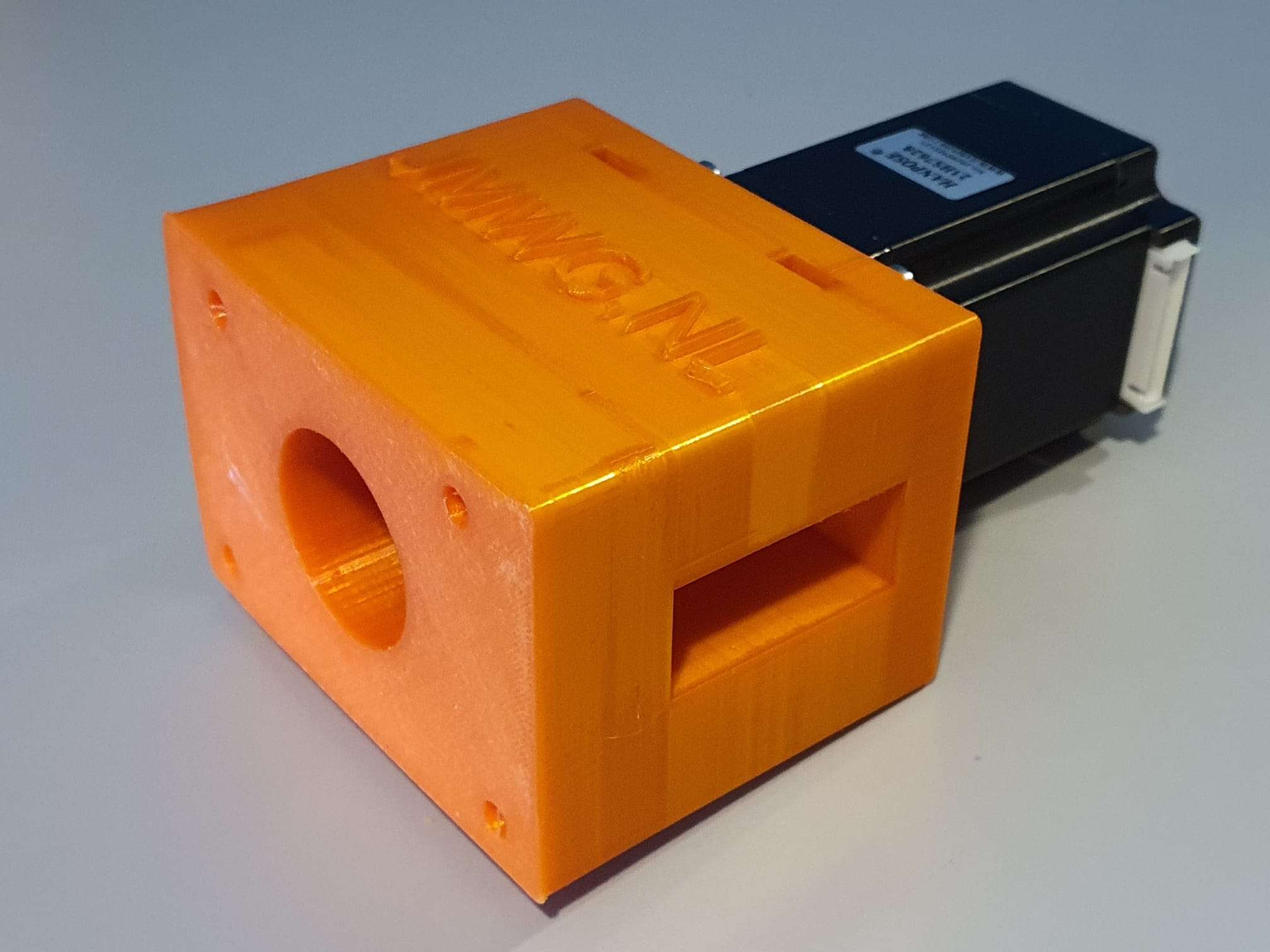
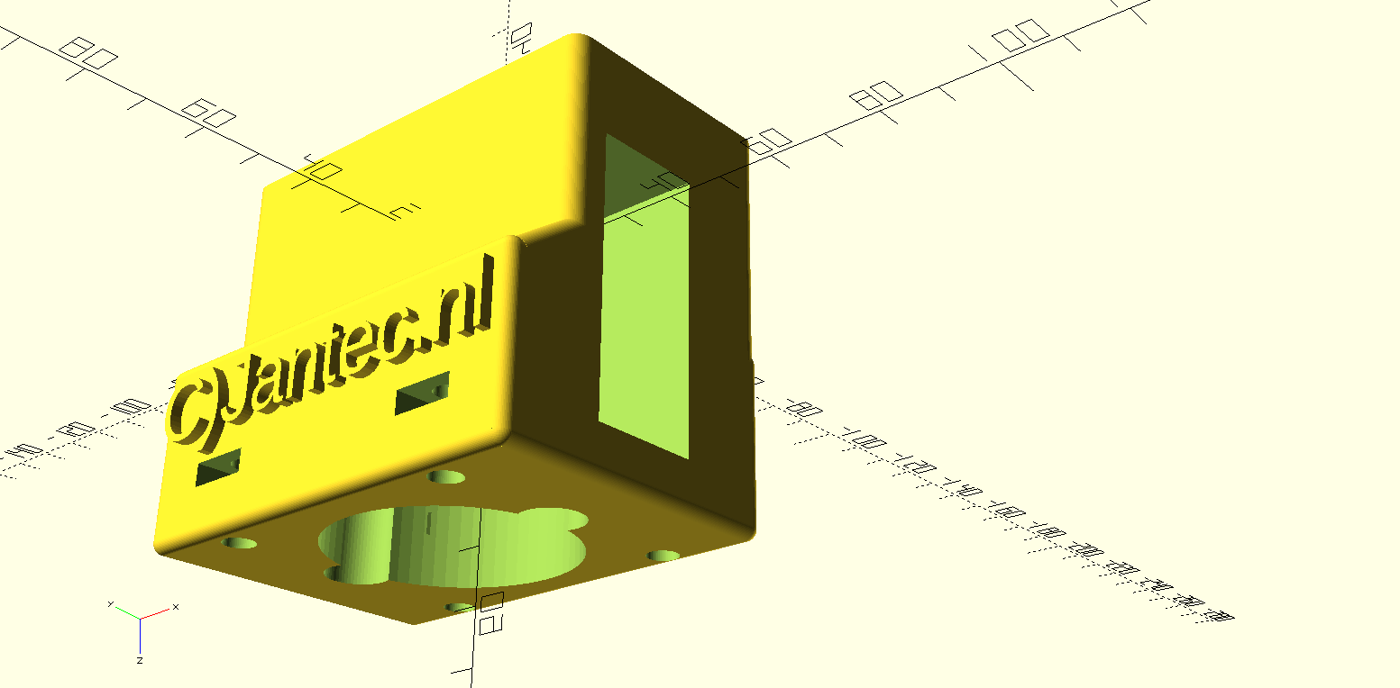
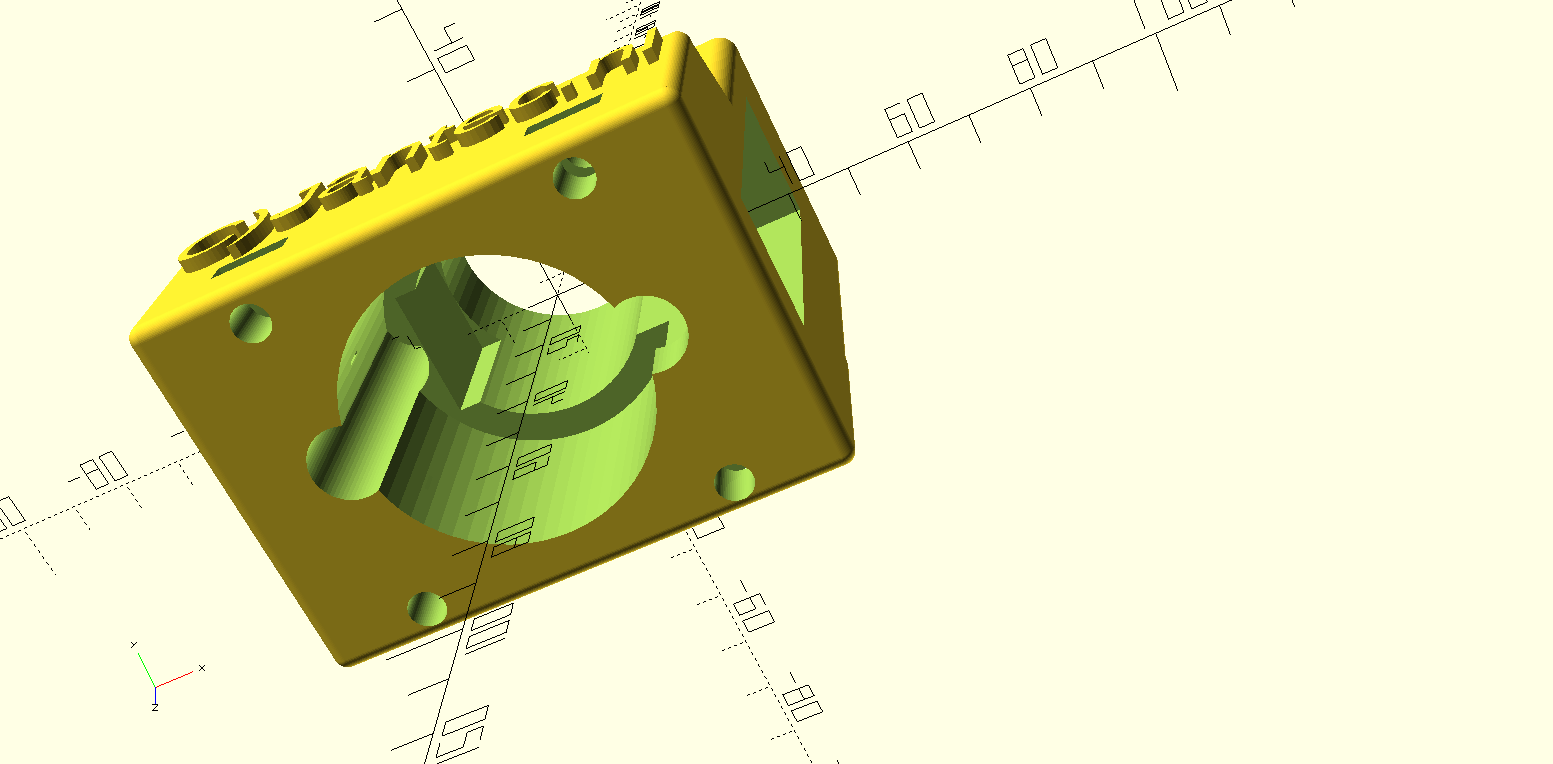
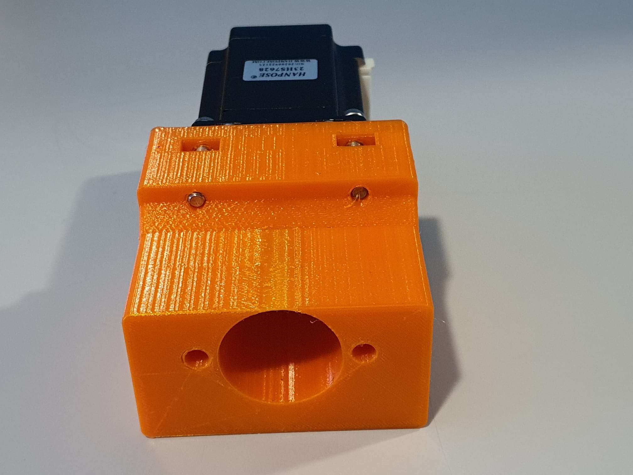
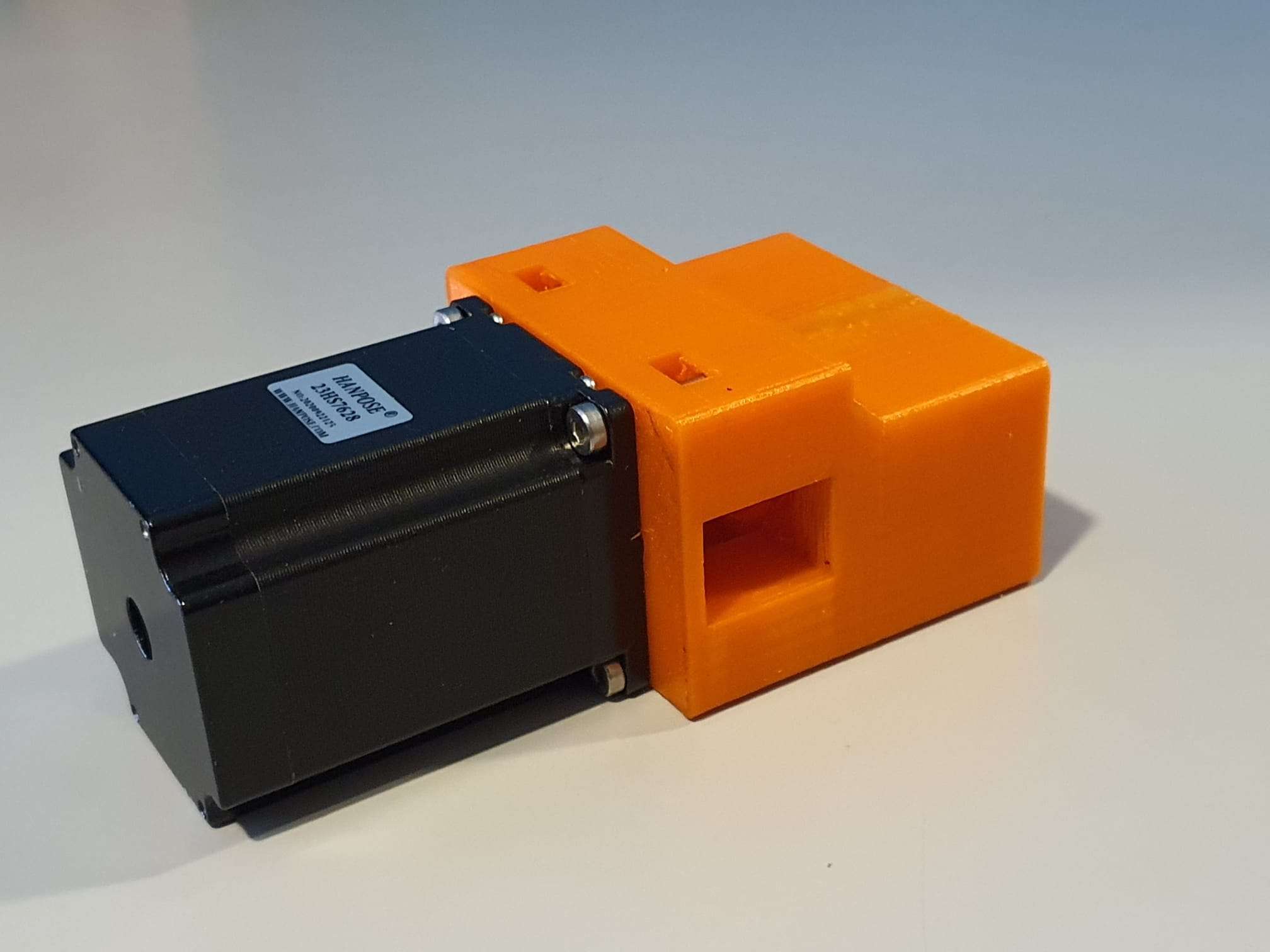
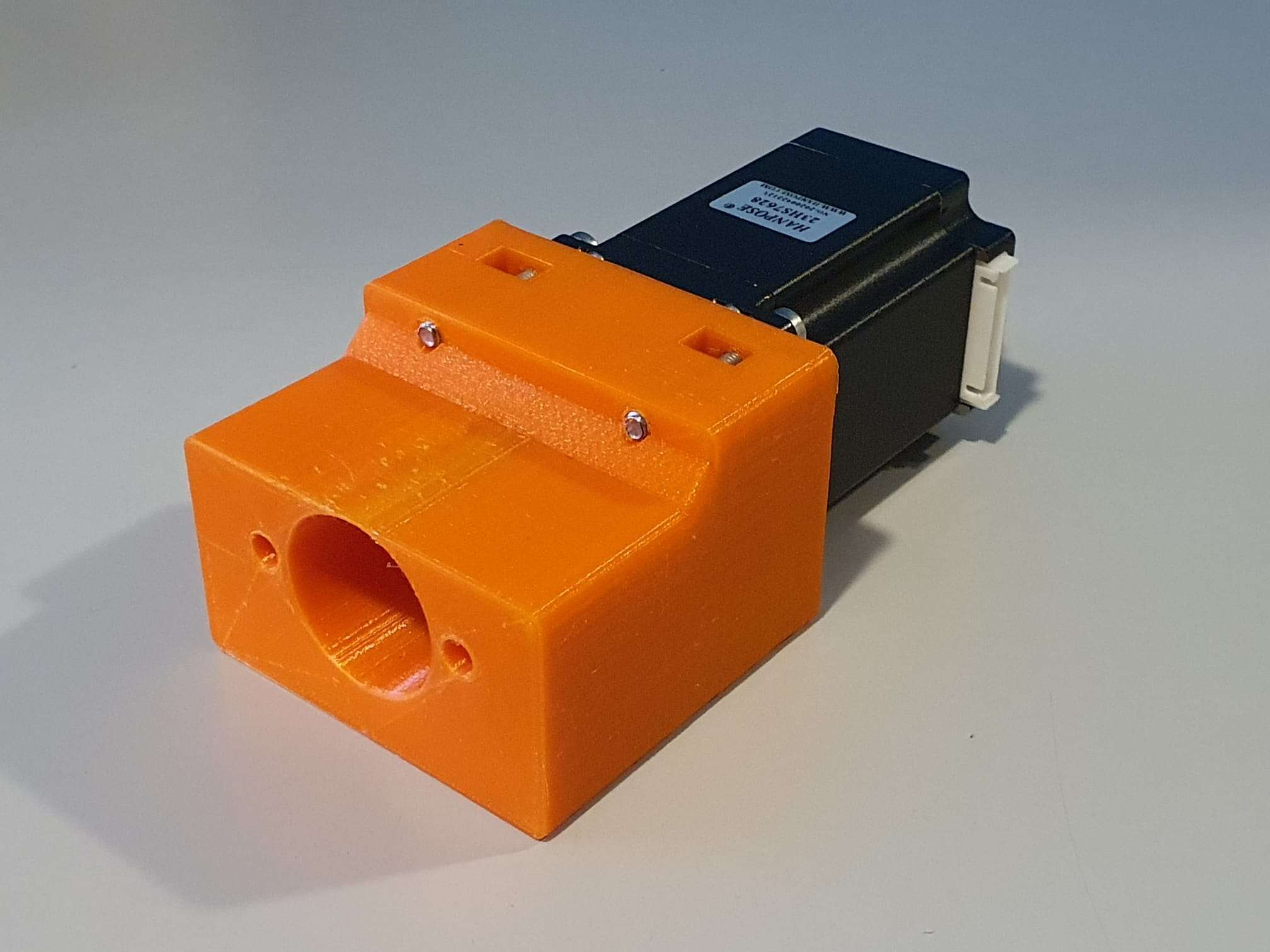
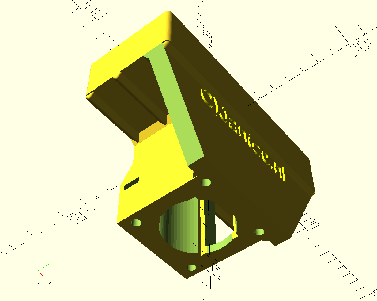
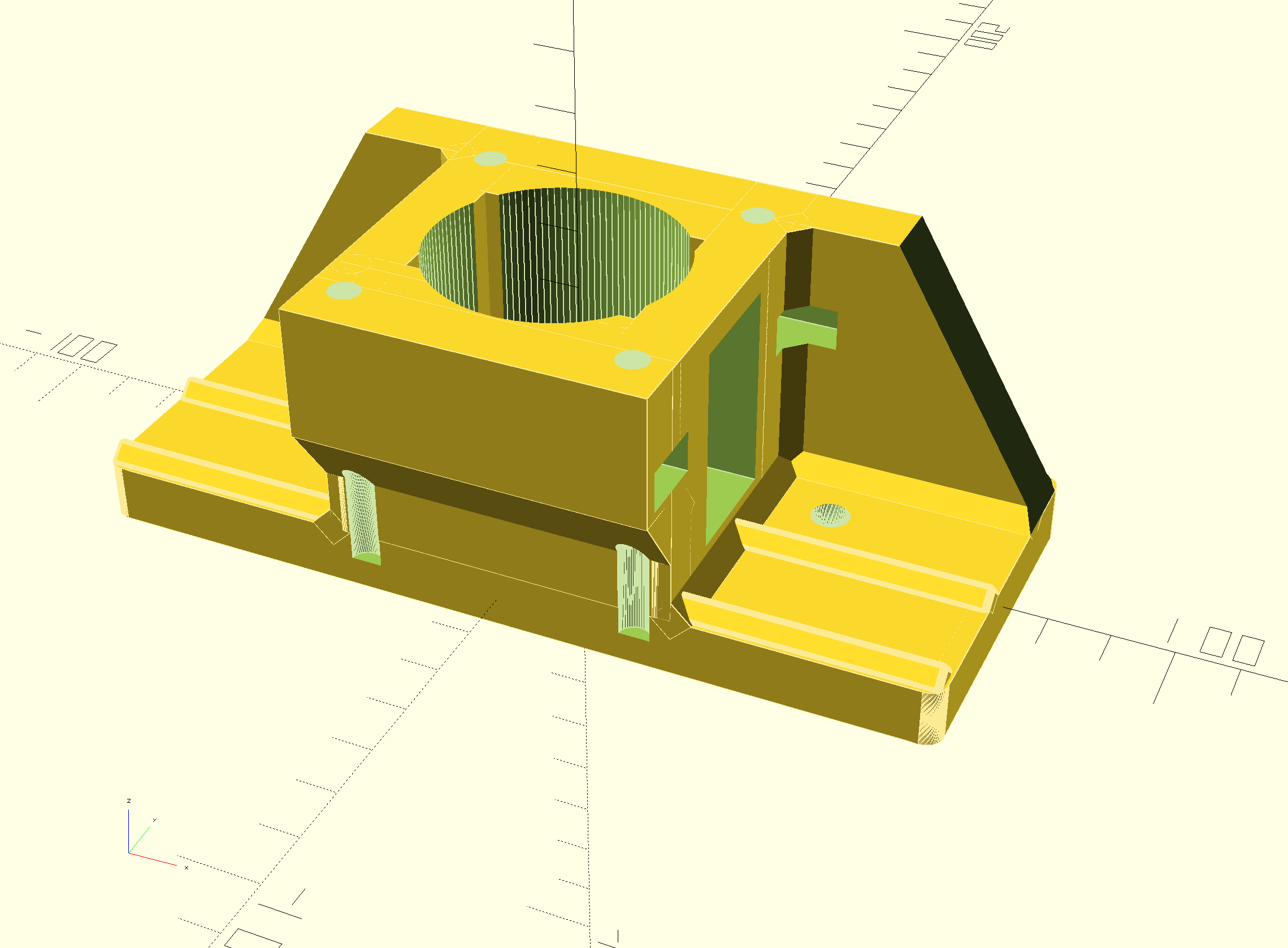
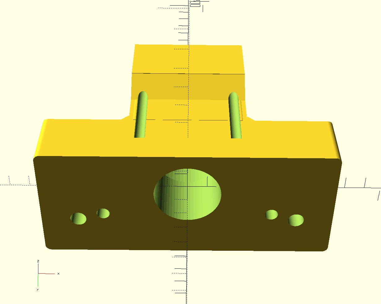
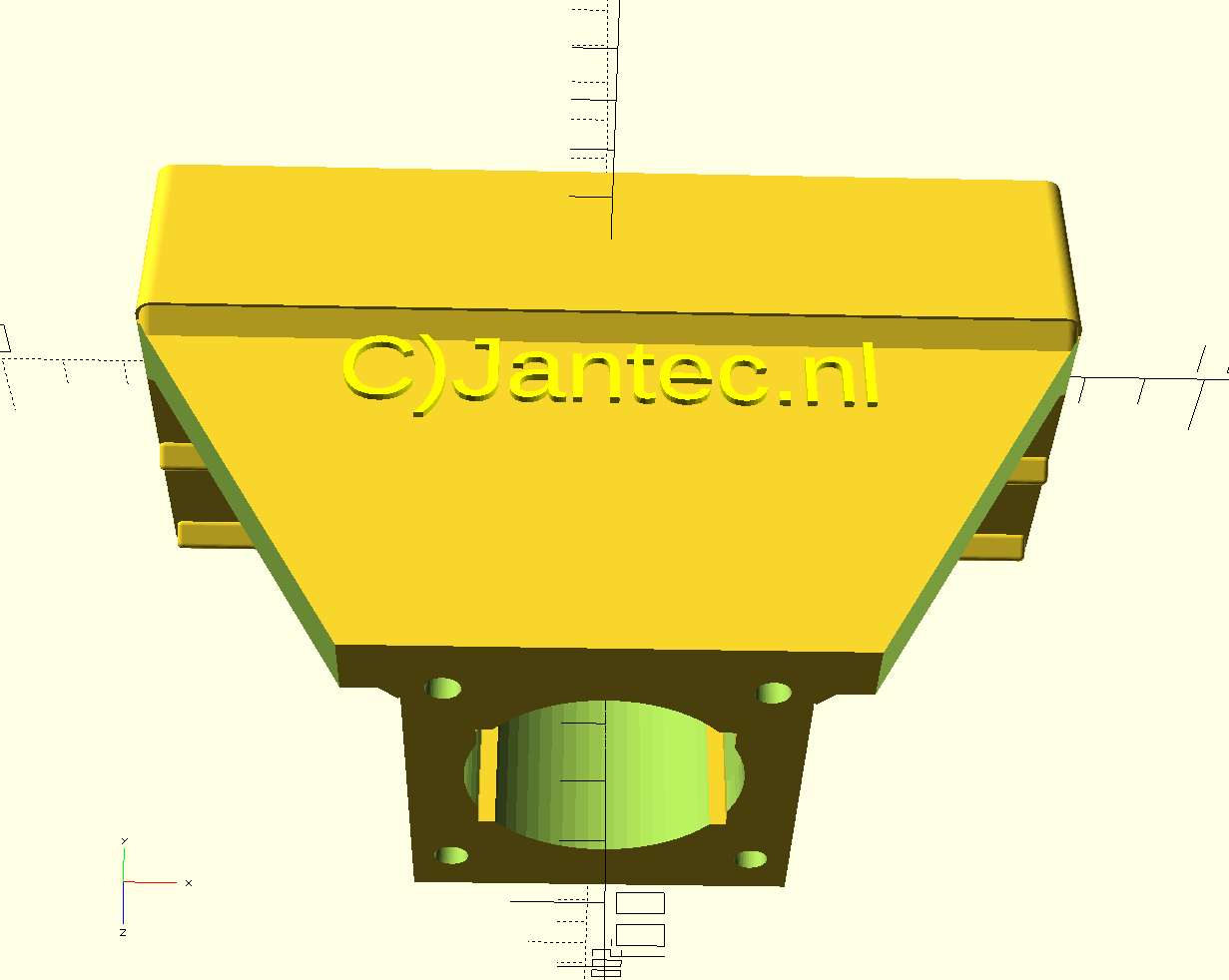
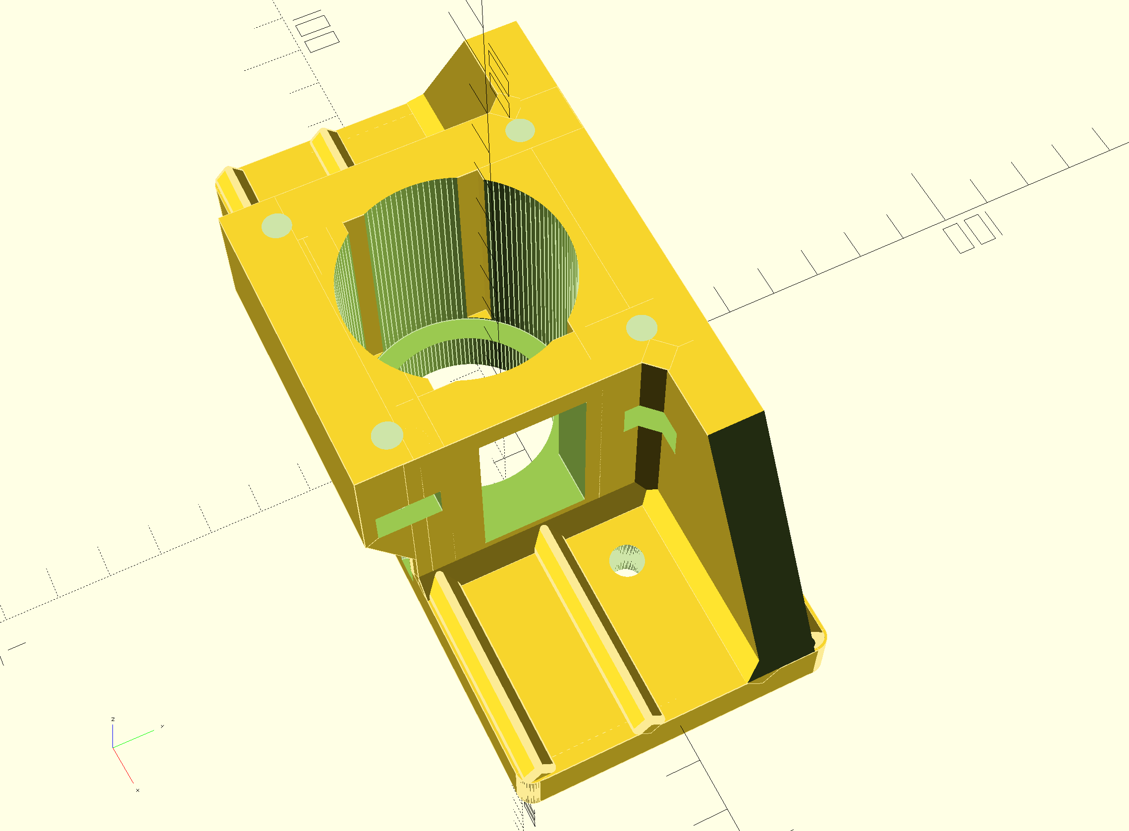
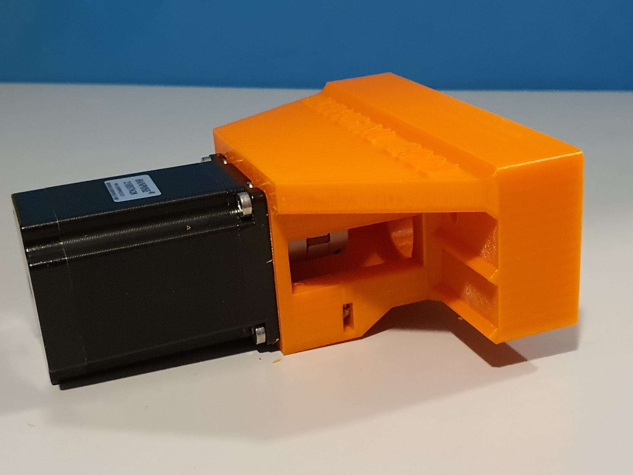
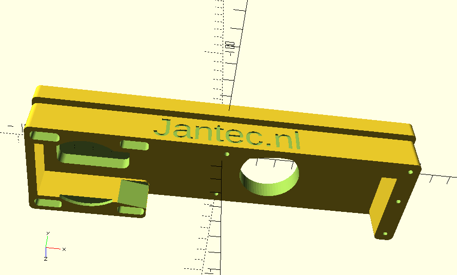
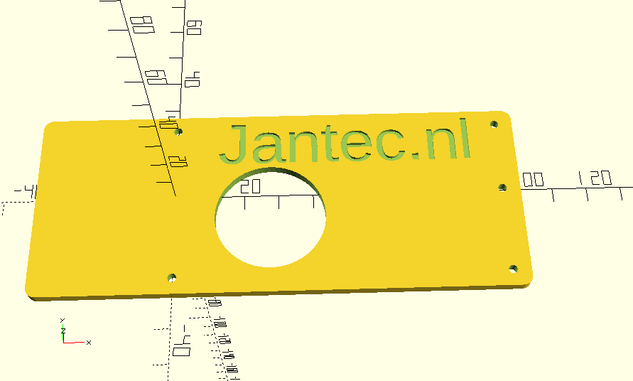
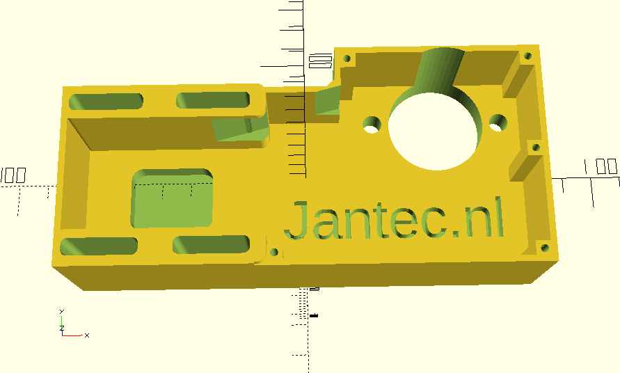
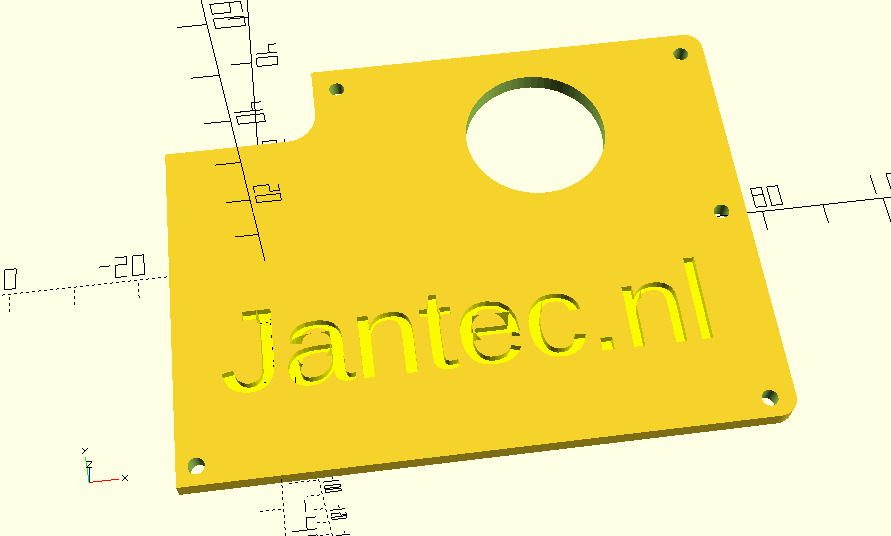
Prints van buisadapters, luchtafvoer en filterhuis

Aanleveren van je ontwerp gaat via mail naar sales@jmwg.nl

Betalen gaat vooraf via ons paypal account of via een tikkie.

Verzendkosten zijn op basis van NLpost tarieven, meestal is dat Eur 6,95.

Wij printen dezelfde dag en versturen de volgende dag. Wil je het sneller of wil je de print(s) ophalen  bel ons dan even of neem contact op via een appje.  Wil je meerdere prints dan kan het wat langer duren voor alles klaar is.

Je kunt bij ons terecht voor het afdrukken van 3D ontwerpen in PLA en PETG tot 50x50x50 cm.  ABS kunnen we printen t/m 22x22x22 cm.

  1. PLA is de goedkoopste optie voor het 3d printen. PLA is perfect voor de meeste toepassingen en is beschikbaar in de basiskleuren zwart, rood, oranje, geel en wit.  PLA heeft meestal een glimmende afwerking.
  2. ABS is de duurste optie voor het 3d printen vanwege de gesloten machines met hogere temperaturen die nodig zijn voor ABS. ABS is voor toepassingen waar extra sterkte nodig is en/of waar de print wordt gebruikt bij hogere temperaturen.  Beschikbare kleuren bij ons in ABS zijn zwart, rood, oranje en wit.  ABS heeft standaard een matte afwerking, en kan op verzoek ook in glanzende afwerking worden geleverd.
  3. PETG zit qua prijs tussen PLA en ABS in en heeft bijna dezelfde eigenschappen als ABS maar is iets minder sterk. De PETG  basiskleuren zijn bij ons zwart, rood, oranje, blauw en wit. PETG heeft meestal een matte afwerking maar is ook met glimmende afwerking te krijgen.  Met de juiste PETG materiaalkeuze is een voedingsmiddelen certificaat leverbaar.
  4. NYLON is onze laatste toevoeging aan het assortiment.  Primair bruikbaar voor automotive toepassingen waar hoge sterkte en flexibiliteit belangrijk is.  Nylon is ook erg goed bruikbaar in de voedingsmiddelen industrie.

Tegen meerprijs kan geprint worden in PLA bronskleur, goudkleur, zilverkleur, eikenmix, berkenmix, rose, paars, donkergroen, donkerblauw, lichtblauw en felgroen.

Mengkleuren zijn ook mogelijk, we kunnen tot 4 kleuren in 1 ontwerp verwerken.

Onze 3d printmachines zijn beschikbaar voor afdrukken met 1 t/m 4 kleuren per print.

Afdrukken met meerdere kleuren zijn 30% duurder i.v.m. materiaalverlies.

We helpen je graag met je ontwerp.

Openscan ontwerpen maken wij voor je tegen uurtarief

Wij adviseren om eerst bij ons een ontwerpafdruk te laten maken om voordat je definitief een ontwerp laat printen,.  Een ontwerp print is sneller klaar en kost ca. 50% minder dan een definitieve print.  Een ontwerpprint wordt op onze delta 3d machine geprint met hoge snelheid en lage(re)  resolutie.  Met een ontwerpprint kun je in het echt zien hoe je ontwerp er uit ziet, met de juiste maten en passing.  Meestal is er nog wel wat aan te passen na de eerste print en dat gaat met een ontwerpprint lekker snel.  Daarna kun je het ontwerp aanpassen en nog een ontwerpprint maken of gelijk de finale 3d print laten maken.  It’s up to you!


FLY 407 board met TFT2.4 inch, wifi en RRF3

2021-05-11

Ik heb vandaag het Mellow Fly 407 board binnen gekregen, en het werkt nu geweldig!

Ik heb de Mellow dedicated wifi unit aangesloten op EXP 1 en EXP2 en op de seriële TFT aansluiting, de microSDcard offline op de PC geprogrammeerd met de bestanden van de voorgestelde Github site en het ging allemaal geweldig!  (De kleine toegevoegde handleiding is erg goed, gewoon de aanwijzingen volgen en het kan niet fout gaan)!

Eerst de firmware van het board gebrand, daarna de firmware van de wifi esp module en na het instellen van de wifi met YAT via USB, heb ik de wifi instellingen geprogrammeerd.  Daarna heb ik met de WDC PC-remote console van de Duet via wifi het FLY 407 moederbord ge-upload met de laatste beschikbare firmware: RRF3.4 beta en de laatste wifi- en DWC versies.

Daarna heb ik de seriële verbinding tussen de TFT aansluiting op het moederbord en de wifi module verwijderd en de BTT 2.4 inch TFT op dezelfde seriële poort aangesloten.  Omdat er maar 1 tft poort beschikbaar is, gebruik ik dezelfde seriële poort die ik gebruikte voor het programmeren van de esp wifi module.  Ik heb de RRF3 firmware al op de TFT unit gezet.

Wel, de resultaten zijn geweldig! Op de TFT na het aansluiten zie je de extruder stappen van 0 naar 1-2-3-4 en weer terug naar 0 dus dit werkt allemaal erg mooi!


Ronde klok WS2812 & Arduino nano

READ THIS ARTICLE IN ENGLISH

In de bovenstaande video zie je alle benodigde onderdelen voor de electronica.  Een arduino Nano, een tijdmodule LS3231 met batterij back-up en een 4-delige ring met elk 15 stuks WS2812 LED’s die zorgen voor een 160mm 60 LED units klok.  Je kunt hem bouwen als een open gebouwde unit zoals hierboven afgebeeld met draad of in een 3d printbare slanke behuizing die ik heb ontwikkeld.  Zie de foto’s hieronder.

Voor het bouwen van deze mooie nauwkeurige klok, kun je mijn ontwerp files voor de behuizing gebruiken op elke 3d printer die een horizontale bed size heeft van minimaal 165x165mm.

Pak de beide print STL’s . HIER. van de Prusa gedeelde site waar ik deze ontwerpen heb geupload. (Als de link breekt, zoek op de prusa site naar ws2812 circulaire arduino klok).

OF haal het STL bestand voor de VOORKANT van de klok van mijn website HIER

EN haal het STL bestand voor de achterkant van de klok van mijn website HIER

Eén STL is voor de achterkant en bevat de Nano box, de andere is voor de voorkant van de klok.  Positioneer de achterste STL 180 graden (dus omhoog gaat omlaag) in uw slicer, zodat zowel de doos als de LED-behuizing op Z-0 niveau zijn, d.w.z. naar beneden gericht op hetzelfde horizontale niveau.   De voorkant kan het best geprint worden met de platte kant naar beneden.  ABS is niet aan te raden omdat het minder stijf is, maar zal waarschijnlijk ook werken.  Voor mij werkt PETG of PLA het beste.

Gebruik wit filament voor het voorste deel, de achterkant kan elke kleur zijn die je wilt.

In de cirkel worden de 4 WS2812 LED segmenten in 1 volledige cirkel van ongeveer 160mm geplaatst.

Als je de elektronica aan de achterkant hebt aangesloten, schuift de voorkant er zo overheen. Geen lijm nodig.  Maar de LED ring kan best op 4 plaatsen met een druppel hotglue aan de basis van de achterste behuizing gelijmd worden.  Dit kun je het beste doen als je zeker weet dat alles goed werkt.

De LED onderdelen zijn verkrijgbaar op o.a. banggood , aliexpress en zo, zoek naar 60LED circle WS2812 die de 160 mm buitendiameter heeft.

Elke LED vertegenwoordigt een punt voor seconden, minuten of als uur indicator.

De kleuren detemine de functie.  Blauw wordt ook gebruikt als kwartier indicator met minder intensiteit, om een gevoel van positionering te hebben voor de andere LEDS als het donker is.

Kijk naar de video hierboven van het ‘open’ demonstratiemodel om te begrijpen hoe het werkt.

Hieronder vindt u de Arduino code voor de gebruikte Nano3, as-is. het werkt voor mij, en in de code vindt u ook alle benodigde elektrische aansluitingen en de specificaties van de gebruikte Time module.

Wanneer aangesloten op je PC, kun je de Arduino programmeren en via de seriële interface kun je naderhand speciale instellingen van de klok wijzigen, zoals helderheid, speciale kwartierverlichtingsindicatoren, enzovoort. het staat allemaal in de code hieronder.

De aansturing kan via een seriële interface met de usb ingang van de Arduino, via een terminalprogramma zoals YAT of met de interface van het Arduino IDE programma.

De commando’s zijn:

f; fader UIT
F; fader AAN
m (getal); dim de 4 blauwe marker LED’s met waarde (getal)
S; synchroniseren met RTC tijd
s; synchroniseren met systeemtijd (computer)
t (tijd); systeemtijd veranderen in:
b; helderheid van alle niet-marker LED’s

Doneer a.j.b. $1 aan mijn paypal account als je (delen van) mijn ontwikkelde materialen gebruikt, zodat ik kan doorgaan met het delen van leuke dingen voor jou om te downloaden

Ik hoop dat alles goed gaat lukken!

Succes,

Jan

De Arduino code, te gebruiken voor het programmeren van de Arduino Nano3 is beschikbaar onderaan dit bericht als platte tekst om te importeren in een leeg arduino bestand (met kopiëren en plakken).

Zorg ervoor dat je alleen de bibliotheken en tijdmodule gebruikt die in de code zijn aangegeven!  De gebruikte tijdmodule is van de betere generatie die de tijd zeer goed vasthoudt, ook in stand-by.

Gebruik voor het verbinden van de draden tussen de neopixel segmenten, de arduino en de tijdmodule een temperatuurgeregelde soldeerbout.  Gebruik een ventilator als je aan het solderen bent en adem geen giftige gassen in tijdens het solderen.

De Arduino code is hieronder weergegeven, te importeren in Arduino IDE in een .ino bestand.  Met de Arduino IDE moet je vervolgens de code compileren om de Arduino Nano geflasht te krijgen met het programma.


/**
* NeoClock
*
* Clock using 60 WS2812B/Neopixel LEDs and DS3231 RTC
* Small changes and updates made by jan Griffioen, Amsterdam Europe 2018-2021
* Libraries needed:
* * Adafruit NeoPixel (Library Manager) – Phil Burgess / Paint Your Dragon for Adafruit Industries – LGPL3
* *
* * Arduino Timezone Library (https://github.com/JChristensen/Timezone) – Jack Christensen – CC-BY-SA
* * Time Library (https://github.com/PaulStoffregen/Time) – Paul Stoffregen, Michael Margolis – LGPL2.1
*/

#include <Adafruit_NeoPixel.h>
#ifdef __AVR__
#include <avr/power.h>
#endif

#if defined(ESP8266)
#include <pgmspace.h>
#else
#include <avr/pgmspace.h>
#endif

/* for software wire use below
#include <SoftwareWire.h> // must be included here so that Arduino library object file references work
#include <RtcDS3231.h>

SoftwareWire myWire(SDA, SCL);
RtcDS3231<SoftwareWire> Rtc(myWire);
for software wire use above */

/* for normal hardware wire use below */
#include <Wire.h> // must be included here so that Arduino library object file references work
#include <RtcDS3231.h>
RtcDS3231<TwoWire> Rtc(Wire);
/* for normal hardware wire use above */

#include <TimeLib.h> //http://www.arduino.cc/playground/Code/Time
#include <Timezone.h> //https://github.com/JChristensen/Timezone

#include <EEPROM.h>

//Central European Time (Frankfurt, Paris)
TimeChangeRule CEST = {“CEST”, Last, Sun, Mar, 2, 120}; //Central European Summer Time
TimeChangeRule CET = {“CET “, Last, Sun, Oct, 3, 60}; //Central European Standard Time
Timezone CE(CEST, CET);

TimeChangeRule *tcr; //pointer to the time change rule, use to get the TZ abbrev
time_t utc;

#define PIN 5

unsigned long lastMillis = millis();
byte dimmer = 0x88;
byte hmark = 0;

byte ohour=0;
byte ominute=0;
byte osecond=0;

boolean fader=true;

Adafruit_NeoPixel strip = Adafruit_NeoPixel(60, PIN, NEO_GRB + NEO_KHZ800);

void setup() {

Serial.begin(57600);

strip.begin();
strip.setBrightness(50);

// Some example procedures showing how to display to the pixels:
// colorWipe(strip.Color(255, 0, 0), 50); // Red
//colorWipe(strip.Color(0, 255, 0), 50); // Green
//colorWipe(strip.Color(0, 0, 255), 50); // Blue
//colorWipe(strip.Color(0, 0, 0, 255), 50); // White RGBW
// Send a theater pixel chase in…
//theaterChase(strip.Color(127, 127, 127), 50); // White
theaterChase(strip.Color(127, 0, 0), 50); // Red
//theaterChase(strip.Color(0, 0, 127), 50); // Blue

//rainbow(20);
rainbowCycle(2);
//theaterChaseRainbow(50);

strip.clear();
strip.show(); // Initialize all pixels to ‘off’

Rtc.Begin();

Rtc.Enable32kHzPin(false);
Rtc.SetSquareWavePin(DS3231SquareWavePin_ModeNone);

if (!Rtc.GetIsRunning())
{
Serial.println(“Rtc was not actively running, starting now”);
Rtc.SetIsRunning(true);
}

if (!Rtc.IsDateTimeValid())
{
// Common Cuases:
// 1) the battery on the device is low or even missing and the power line was disconnected
Serial.println(“Rtc lost confidence in the DateTime!”);
}

byte eechk = EEPROM.read(0);
if(eechk == 0xAA) { //Assume this is our config and not a fresh chip
dimmer = EEPROM.read(1);
hmark = EEPROM.read(2);
fader = EEPROM.read(3);
}

timeSync();
}

void calcTime(void) {
utc = now();
CE.toLocal(utc, &tcr);
ohour = hour(utc);
ominute = minute(utc);
if(osecond != second(utc)) {
osecond = second(utc);
lastMillis = millis();

if(ominute == 0 && osecond == 0) {
//Every hour
timeSync();
}
}
}

void addPixelColor(byte pixel, byte color, byte brightness) {
color *= 8;
uint32_t acolor = brightness;
acolor <<= color;
uint32_t ocolor = strip.getPixelColor(pixel);
ocolor |= acolor;
strip.setPixelColor(pixel, ocolor);
}

void drawClock(byte h, byte m, byte s) {
strip.clear();

addPixelColor(m, 1, dimmer);

if(hmark > 0) {
for(byte i = 0; i<12; i++) {
addPixelColor((5*i), 2, hmark);
}
}

h %= 12;
h *= 5;
h += (m/12);
addPixelColor(h, 2, dimmer);
// 0x RR GG BB

if(fader) {
byte dim_s1 = dimmer;
byte dim_s2 = 0;
byte px_s2 = s+1;
if(px_s2 >= 60) px_s2 = 0;
unsigned long curMillis = millis()-lastMillis;
if(curMillis < 250) {
dim_s2 = 0;
dim_s1 = dimmer;
}else{
dim_s2 = map(curMillis, 250, 1000, 0, dimmer);
dim_s1 = dimmer – map(curMillis, 250, 1000, 0, dimmer);
}

// Add blue low intensity dots for 12(0),3, 6 and 9 O’çlock to verify where the clock is positioned..
addPixelColor(15, 128, 10);
addPixelColor(30, 128, 10);
addPixelColor(45, 128, 10);
addPixelColor(0, 128, 40);

addPixelColor(s, 0, dim_s1);
addPixelColor(px_s2, 0, dim_s2);
}else{
addPixelColor(s, 0, dimmer);
}

// add a background color
// setBrightness(Serial.parseInt());
// uint16_t j;
// for(j=0; j<60; j++) { // 1 cycles of colors on wheel
// strip.setPixelColor(j, Wheel(((j * 256 / strip.numPixels()) + j) & 255));
// }

strip.show();
}

byte rounds = 0;

void loop() {
calcTime();

if(rounds++ > 100) {
Serial.print(ohour);
Serial.print(“:”);
Serial.print(ominute);
Serial.print(“:”);
Serial.print(osecond);
Serial.println(“(C)JG-2020”);
rounds = 0;

}
//rainbow(21);
if (osecond == 59){theaterChase(strip.Color(0, 0, 127), 40); }// Blue; }
//if (ominute == 59 AND osecond == 59){theaterChase(strip.Color(0, 127, 0), 50); }// Green}
//if (ohour == 11 AND ominute == 59 AND osecond == 59){theaterChase(strip.Color(127, 127, 0), 50); }// Green}
else {drawClock(ohour,ominute,osecond);}

delay(10);

chkSer();
}

void timeSync(void) {
RtcDateTime dt = Rtc.GetDateTime();
setTime(dt.Hour(),dt.Minute(),dt.Second(),dt.Day(),dt.Month(),dt.Year());

Serial.print(“Synced to: “);
Serial.print(dt.Year());
Serial.print(“-“);
Serial.print(dt.Month());
Serial.print(“-“);
Serial.print(dt.Day());
Serial.print(“-“);
Serial.print(dt.Hour());
Serial.print(“-“);
Serial.print(dt.Minute());
Serial.print(“-“);
Serial.println(dt.Second());
}

void timeSave(void) {
utc = now();

RtcDateTime store = RtcDateTime(year(utc), month(utc), day(utc), hour(utc), minute(utc), second(utc));
Rtc.SetDateTime(store);

Serial.print(“Synced to: “);
Serial.print(year(utc));
Serial.print(“-“);
Serial.print(month(utc));
Serial.print(“-“);
Serial.print(day(utc));
Serial.print(“-“);
Serial.print(hour(utc));
Serial.print(“-“);
Serial.print(minute(utc));
Serial.print(“-“);
Serial.println(second(utc));

}

void setBrightness(byte brightness) {
dimmer = brightness;
}

void chkSer(void) {
unsigned int iy;
byte im,id,iH,iM,iS;

if(!Serial.available()) return;

switch(Serial.read()) {
case ‘b’:
setBrightness(Serial.parseInt());
Serial.print(F(“Brightness changed to: “));
Serial.println(dimmer);
EEPROM.put(0, 0xAA);
EEPROM.put(1, dimmer);
break;
case ‘t’:
iy = Serial.parseInt();
im = Serial.parseInt();
id = Serial.parseInt();
iH = Serial.parseInt();
iM = Serial.parseInt();
iS = Serial.parseInt();
setTime(iH,iM,iS,id,im,iy);
Serial.println(F(“System time changed”));
break;
case ‘f’:
fader = false;
EEPROM.put(0, 0xAA);
EEPROM.put(3, 0);
Serial.println(F(“Fader off”));
break;
case ‘F’:
fader = true;
EEPROM.put(0, 0xAA);
EEPROM.put(3, 1);
Serial.println(F(“Fader on”));
break;
case ‘m’:
hmark = Serial.parseInt();
EEPROM.put(0, 0xAA);
EEPROM.put(2, hmark);
Serial.println(F(“HMark changed”));
break;
case ‘s’:
timeSync();
Serial.println(F(“Synced RTC to System”));
break;
case ‘S’:
timeSave();
Serial.println(F(“Synced System to RTC”));
break;
default:
Serial.println(‘?’);
}
}

// Fill the dots one after the other with a color
void colorWipe(uint32_t c, uint8_t wait) {
for(uint16_t i=0; i<strip.numPixels(); i++) {
strip.setPixelColor(i, c);
strip.show();
delay(wait);
}
}

void rainbow(uint8_t wait) {
uint16_t i, j;

for(j=0; j<256; j++) {
for(i=0; i<strip.numPixels(); i++) {
strip.setPixelColor(i, Wheel((i+j) & 25));//255
}
strip.show();
delay(wait);
}
}

// Slightly different, this makes the rainbow equally distributed throughout
void rainbowCycle(uint8_t wait) {
uint16_t i, j;

for(j=0; j<256*5; j++) { // 5 cycles of all colors on wheel
for(i=0; i< strip.numPixels(); i++) {
strip.setPixelColor(i, Wheel(((i * 256 / strip.numPixels()) + j) & 255));
}
strip.show();
delay(wait);
}
}

//Theatre-style crawling lights.
void theaterChase(uint32_t c, uint8_t wait) {
for (int j=0; j<4; j++) { //do 4 cycles of chasing
for (int q=0; q < 3; q++) {
for (uint16_t i=0; i < strip.numPixels(); i=i+3) {
strip.setPixelColor(i+q, c); //turn every third pixel on
}
strip.show();

delay(wait);

for (uint16_t i=0; i < strip.numPixels(); i=i+3) {
strip.setPixelColor(i+q, 0); //turn every third pixel off
}
}
}
}

//Theatre-style crawling lights with rainbow effect
void theaterChaseRainbow(uint8_t wait) {
for (int j=0; j < 256; j++) { // cycle all 256 colors in the wheel
for (int q=0; q < 3; q++) {
for (uint16_t i=0; i < strip.numPixels(); i=i+3) {
strip.setPixelColor(i+q, Wheel( (i+j) % 255)); //turn every third pixel on
}
strip.show();

delay(wait);

for (uint16_t i=0; i < strip.numPixels(); i=i+3) {
strip.setPixelColor(i+q, 0); //turn every third pixel off
}
}
}
}

// Input a value 0 to 255 to get a color value.
// The colours are a transition r – g – b – back to r.
uint32_t Wheel(byte WheelPos) {
WheelPos = 255 – WheelPos;
if(WheelPos < 85) {
return strip.Color(255 – WheelPos * 3, 0, WheelPos * 3);
}
if(WheelPos < 170) {
WheelPos -= 85;
return strip.Color(0, WheelPos * 3, 255 – WheelPos * 3);
}
WheelPos -= 170;
return strip.Color(WheelPos * 3, 255 – WheelPos * 3, 0);
}

5-voudige cold/hotend combinatie voor mijn A30M


Deze 5-voudige hot-en cold end combinatie wordt geinstalleerd op mijn A30M met het Duet2wifi board+extension board (5-voudig met plug-in drivers).

De A30M heeft al onafhankelijke Z-stepper motoren.

De Duet2wifi heeft 5 stappenpoorten, en het uitbreidingsbord heeft ook 5 stappenpoorten.  X,Y,2xZ, en 5 Extruders is een totaal van 9 dus dit gaat inderdaad passen!

Ik zal nieuwe bedrading maken voor de 5 extruder steppers boven op het A30M frame met 5 bowden buizen naar de hotend.

Aangezien de hotend niet mengt, zal dit een eenvoudige klus zijn om in config.g. te krijgen.

Voor de slicer zal het ook eenvoudig zijn.

Voeg gewoon de extruders toe tot een totaal van 5 stuks.

Voeg de juiste filamenten/temps/ geen offset toe dus zet offset X en Y op 0.

Het werk zal voornamelijk zitten in de tool changing files voor T0-T5 waar retraction- en extruding settings nodig zullen zijn.

Zoals ik n u werk met de 4-voiudige toolchanger van E3D kun je beter de retractie door de slicer laten uitvoeren, dus daar ga ik in eerste instantie mee aan de slag!

Voor de hotend heb ik een nieuwe setup beschikbaar waarmee ik snel de nozzle kan veranderen.

Dit zal het mogelijk maken om deze setup voor allerlei toepassingen te gebruiken.

Qua hardware moet ik nog wel een plekje vinden voor de Z-sensor, zo dicht mogelijk naast het hotend.

Are professional 3d printers overpriced?

For what it’s worth, the articles I write are not only based on my opinion and experience,  common sense is also part of my written content.

In the first place you should ask ourself what you would define to be a professional 3d printer. Is it about price, durability, quality, size, usability, repeatability, speed, portability, cloud-based usage, shared usage, or possibly some other requirement that you find inportant? If you read the world’s professional literature about 3d-printing, it is always about either making one-off products or prototypes for complex (machine, dental, medical) purposes, or it has to do with printing parts in series for a specific branch of industry.  In both cases, the to be printed material is mostly nothing like the hobbyist uses. Professional printing goes from carbon/fiber to stainless steel, ceramics, titanium and so on.  Most professional production printers are in the price range above 30 k Euro.

3d printers from 500 Euro up until 15 k Euro are usually very good and precise at printing with common materials like ABS/PLA/Nylon/PetG, Carbon/wood et cetera and have a higher price tag than standard consumer models due to specific added value like the ability to print really big models, heated chamber, multicolor et cetera.

The X1 160Pro™ is the world’s largest metal binder jetting system and is now shipping to customers. A controlled-atmosphere model of the system, capable of high-volume aluminum and titanium production, will be available in late 2022. (Photo: Business Wire)And- after printing, most of these printed parts need post-processing like sintering for aluminium.

BigRep Pro 3D Printer | KeeraTech
BigRep PRO™

The price for professional 3d printers is a summation of a number of  drivers, like:

  1. Developing / staffing
  2. Developing / materials, software and so on
  3. Tools, offices, warehouse and so on
  4. Patents costs
  5. Price and quality of materials
  6. Production costs
  7. Marketing costs
  8. Post-delivery costs (Service/maintenance)

With the hobbyist’s 3d printers, there is really only one driver for the costs, which is materials and production.  Of course the quality is an issue here because cheap parts of lesser quality will make products of lesser quality. All other drivers from the above list are not required and/or have already been put in the public domain and are therefore not put in the final selling price. With professional 3d printers, the production numbers are usually low, quality high and developing processes are usually lengthy and expensive.  Thus, the price per sold 3d printer will be uplifted a lot from the development related costs. On top of this, the real development of 3d printing is not even starting.  The pioneers that develop printers will have to keep developing over and over again.  Only when professional 3d printers will be in a stable production phase and development is more like tweaking than making large steps, it is possible to see prices drop.

So- to answer the question: No, professional 3d printers are not overpriced. But- they are expensive and are only interesting if you already need products that can be made today with such a specific printer. Think of car parts development, Formula 1- engine developments and so on.  In these industries, it is very expensive to get a mold and rework a rough newly developed product in the conventional way so a 3d metalprinter will fulfill an already existing need.  And the investment will pay back very quick due to the fast production times. And- the engineers that design a part can just use their existing tooling to make designs  for 3d printing.

independant Z-axis with FLY-CDY-V2

I replaced my Duet2wifi with the Mellow’s FLY-CDY-V2 motherboard

My cloned Duet2wifi MB that was running in my I3 bear suddenly refused to start up any longer, so I decided to put my recently purchased Mello FLY-CDY-V2 motherboard in the I3 bear printer.  Up to now, the makerbase Duet2wifi clones keep working properly and all other clones die on me…

During the replacement process I encountered the following issues:

  1. The microSD card sleeve on the board was loose on 1 side. I noticed that the board just got in a frozen status now and then.  The solution I finally discovered was that the microSD card holder had to be soldered back to the board, so the SD card made better contact with the little metal parts inside the holder.  Since the repair, no problems anymore!
  2. The connectors of the Fly vboard are standard X254 connectors, which I prefer.  But, the Duet uses propriatary ones so I had to replace all connectors.  But, I shortened all cables in doing this so I now have a very neat looking etup.
  3.  I had to print a new case for this board. I found only 1 available version that also had a fan in the cover.  Slick and well ventilated.  Available on Thingiverse!
  4. The available help on internet like Github pages are all well documented but you must be certain to choose the V2 version of the board for firmware and so on since the FLY-CDY (without V2) is a completely different board with another processor (LPC).  be aware that things are not comparable between the two boards.  The V2 is not just an upgrade!
  5. The rest on the board is quite clear with regards to usage and placement. All self-explainatory.
  6. The only way to connect your paneldue is via the serial 4-pin connector.  The block cables don’t work ‘as-is’.  The paneldue works flawless.
  7. The firmware and DWC software works very well on this STM32-based board. Also updating works flawlesssly.
  8. The difference that matters most to me is some little issues like different naming conventions, pin naming differences between the 2 boards and so on.  Nothing very difficult but is makes it impossible to swap your configs between the boards without some editing.  I would thing=k that cloning should be done more reliable, that would make the board sell better imho.
  9. There is no breakout/expansion port.  Due to the chosen processor, the potential of the Due2wifi with the many expansion possibilities is niot available on the CDY-FLY-V2.
  10. What you do get on the FLY-CDY-V2:
    1. Neopixel port up to 60 WS2812 LEDS (10 max or more with seperate 5V PSU)
    2. max 4 heaters ( 1 bed, 3 other) 
    3. max 4 temp sensors (1 bed, 3 others)
    4. max  3 controllable (PWM) fan outputs
    5. max 6 steppers with any sort of (pluggable) drivers (UART only, no SPI)
    6. max 6 end- (or other) switch inputs
    7. 12-36 Volt power input
    8. BLtouch port fully functional
    9. wifi unit
    10. DWC webbased DUET2wifi controllable
    11. Laser port
    12. A limited number of controllable GPIO pins are available on the EXP2 and EXP 1 port, this could be used for driving accessories like magnets, valves, extra LED’s and so on (via uplifters/Mosfet boards)
    13. Jumper for setting the power to the min/max switches at VCC or 5V (choose 5V!!)
    14. If you want, the option to have PT100 chip installed gives you 1 input for PT100
    15. The Duet2wifi firmware suite is available for this board through a specific development Github page, and as long as this is maintained updates for the board’s reprap firmware and DWC are available.

FLY CDY V2 SDcard content download

Since the FLY_CDY_V2 STM32 board comes without any firmware installed, I made a simple link for you to download and extract everything you need to a 2-16GB microSDcard. 

Just download, extract, burn as-is to SD and plug it in the board, fire the board up and all works!

Make sure you follow the guideline HERE for getting attached to the board via wifi by using a USB cable and YAT terminal on your PC to get the home wifi SSID and Password programmed to ROM into the board, AFTER you installed firmware by putting in the SDcard and firing it up.

The settings in config.g at the SDcard are made for a Cartesian XYZ machine with triple extruder.  This can all be changed to fit your build in config.g. 

For a delta, use THIS DUET2wifi DELTA config.g and change the pin_name of bed heater  according to the FLY_CDY_V2 name convention (thus: use bed instead of bed_heater).  

For more info about the board and connecting to the electronics, steppers, endstops, filament sensors, BLTouch, Neopixels etcetera go HERE

Please donate $1 to my paypal account if you use (parts of) my developed materials so I can continue to share nice stuff for you to download


Cheers,


Jan Griffioen

Geeetech A30M rebuilt with Duet2wifi


The motherboard of my Geeetech A30M was broken, due to a defective Y-axis motor as I experienced later.  I ordered a new Smartto motherboard from Geeetech, installed it and it broke down again, due to the shortcut in the Y motor. Very strange defect since the smartto board uses plug-in drivers.  However, unrepairable and a real pity to now be stuck with 2 smartto boards without any use for them with both having a defect on the Y output.   Exchanging drivers did not help, cables exchange did not help either…

the original smartto motherboard

After replacing the Y-motor,I decided to go for a complete rebuild of the A30M.  In the old files you can still see the original smartto experiences on the A30M HERE.

Above, the movie of the first Duet2wifi experiences and the Chimera hotend.  Later, I decided to make the extruders direct-driven.

Get my  A30M config.g for reprap 3 Duet2wifi  for the original mixing hotend (1 nozzle, 2 extruders).

Get my hotend to motherboard cable and pin assignment  via the following link: 2020 12 09 improved A30M Extruder toolhead cable to board after adding dual hotend dual nozzle dual heater and dual temp sensors

The chimera hotend, combined with dual direct drive bondtech extruders


This is the Paneldue 4.3 inch touch panel as mounted in the A30M case, with a very slim bezel since the Paneldue is mounted flush with the front of the A30M case.

2GSpro Delta rebuilt with Duet2wifi reprap 3.2.2 auto config G32

Delta 2GS Duet2wifi

April 2021: My first 3d printer I bought back in 2014 finally got the Duet2wifi motherboard installed with 2 new extruders, piëzo Z-probe, new hotend, cabling, power supply, 24 Volt hotbed and 24 Volt fans.

The original motherboard is based on an Arduino Mega and had trouble keeping up with the latest firmware versions.

Besides that, I really want all my printers to have a sturdy wifi accessibility to manage them remotely.

The Duet has proved to be both reliable as easily configurable.

Paneldue 4.3 inch for Delta 2GSpro

The electronics has been rebuilt to 24 Volt and two Bondtech extruders have been installed, 1 left- and 1 right handed version. But- for the time being only 1 hotend got installed. I will install a properly working mixing hotend later. Or maybe a dual switching hotend, just to try it out.

Underneath the G2S pro delta with Duet2wifi board

One of the advantages of the Duet is the reprap firmware.  With a delta, reprap 3.2.2 has a G32 command which automatically configures all the difficult settings for the Delta printer like rod lenghts, endstop settings et cetera.  Provided that you have a bed.g file with enough 6 or 7-factor probe points.

I used the heater pins of the 2nd extruder as PWM power supply for my LED toplights.  If I ever install a dual hotend with 2 nozzles, I will add a Mosfet board  that converts 3.3 Volt to 24 Volt and then I will use a spare bed heater pin (most likely GPIO heater pin 4 or five) for the LED top light.  This works very well on all my other Duet boards where I connected LED lights to the printer . The LED’s are controlled via the PanelDue touchscreen (macros) and via the start/stop files.

All you need to measure yourself to  get the Delta configured is the Z-probe offset versus the nozzle position and the rest will be done through the G32 command.  The sequence is:  Perform G28, G32, M500, G29 and you’re done.  You will have to get the bed.g file for the G32 command to work as such from the escher3d website.  I used the 7-factor version.

PS: You don’t need to calibrate G29 at every print.  Please look at my homing file for the delta where-, after homing X-Y-X=Z to the top I only have a Z-probe G30 at the bed’s surface.  I will attach my final config.g code and all needed additional code for the delta with reprap 3.2.2 so you can benefit from my config.g for the Duet2wifi learnings HERE.  Cheers, Jan

Delta 2GS Duet2wifi
The full Delta2GSpro printer with topLED’s

PM: Things that are really needed: The Z-probe MUST be as close to the nozzle as  possible.  I had a BL Touch earlier which was positioned to the side of the center carriage and this never worked as supposed to.  It was positioned at 45 mm to the right and 25 mm to the front of the nozzle and this was clearly too far away to get a decent probing for G32.  With the BL Touch I never got good Delta basic settings.  The Piezo nozzle is a slim 6mm diameter version and has been strapped to the cold end of the E6D with a set of 1mm wires  and works perfect.

Onze 3d printers, bestuurd via OCTOPI of Duet’s Web-based app

Boven: Onze Dual Bear I3 dual color 3d printer met onafhankelijke carriages, op afstand gemanaged met DUET’s webinterface.

De Octopi oplossing werkt met een Raspberry PI, en daarop de Octopi firmware.  Het apparaat stel je in op je wifi en je sluit het aan op je 3d printer’s USB. Vervolgens heb je een webinterface op het IP adres van de Raspberry waarmee je alle zaken van je aangesloten printer kan managen.  Alle instellingen zoals temperatuur, mesh, en eigenlijk alles wat je ook via een lokaal LCD kan managen.  En- je kan je jobs naar de raspberry uploaden en starten/managen en bijstellen qua temperatuur  en dergelijke.  Wat ik erg fijn vind is dat je een raspberry camera kan aansluiten en zo je jobs kan volgen.

De Duet vind ik qua gebruik en mogelijkheden prettiger. omdat je naast alles dat de octopi kan, ook de systeemfiles online kan aanpassen.  En printerupdates kan doen, direct in de firmware.  Bovendien heb je geen aparte doos nodig omdat de Duet2wifi alles al aan boord heeft.

Nadeel is dat je aan de Duet geen camera kan hangen. Er is wel een mogelijkheid em een IP camera te integreren in de DWC, Duet’s web based remote app.  En zo’n wifi IP-camera is zelf makkelijk te maken met een goedkope esp unit.

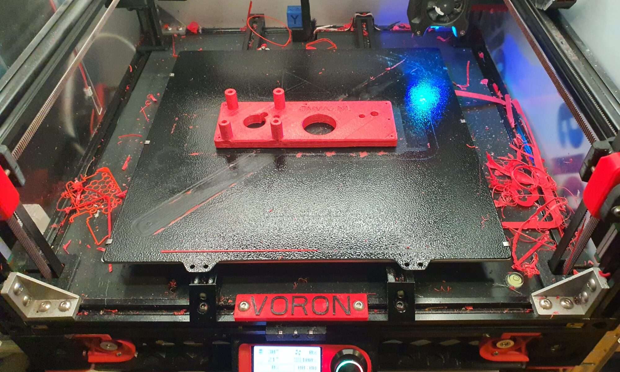
Boven: De Voron 2.4, printmaat 300x300x220 mm.  De Voron werkt met een ingebouwde Raspberry PI, en een op Klipper gebaseerde firmware die OCTOPI als basis gebruikt voor de romote management mogelijkheden.

Prusa Bear I3plus with mods dual Z axis control with DUET2wifi


Kingroon Kp3S heavily modded with new firmware and tool fan, connected to an OCTOPI


Twotrees Sapphire PRO with new firmware, also connected to wifi via an OCTOPI


Voron 2.4 for Nylon and ABS printing, with external exhaust and 300+ degC printhead, bed up to 150 degC, with Klipper/ Octopi based Raspberry PI, and 2 pieces of SKR1.4turbo.


Prusa i3 mini original, the production monster for PETG.  This machine is also connected with an OCTOPI, this works very well!


En de VoreXY Twotrees Sapphire pro, onze perfecte printer voor snelle productie, aangesloten via OCTOPI


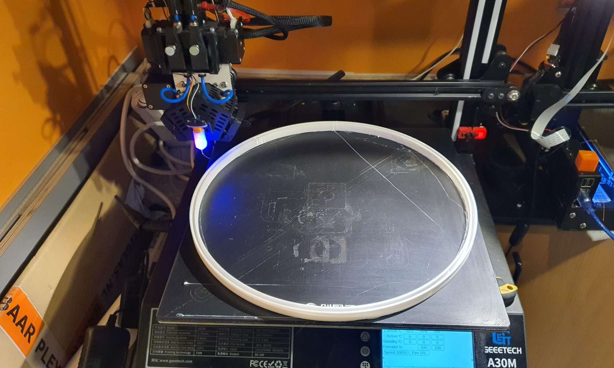
En de multicolour geheel aangepaste Geeetech A30M dual head printer met het nieuw geinstalleerde Duet2Wifi motherboard, dual Chimera heatblock en direct drive extruders