

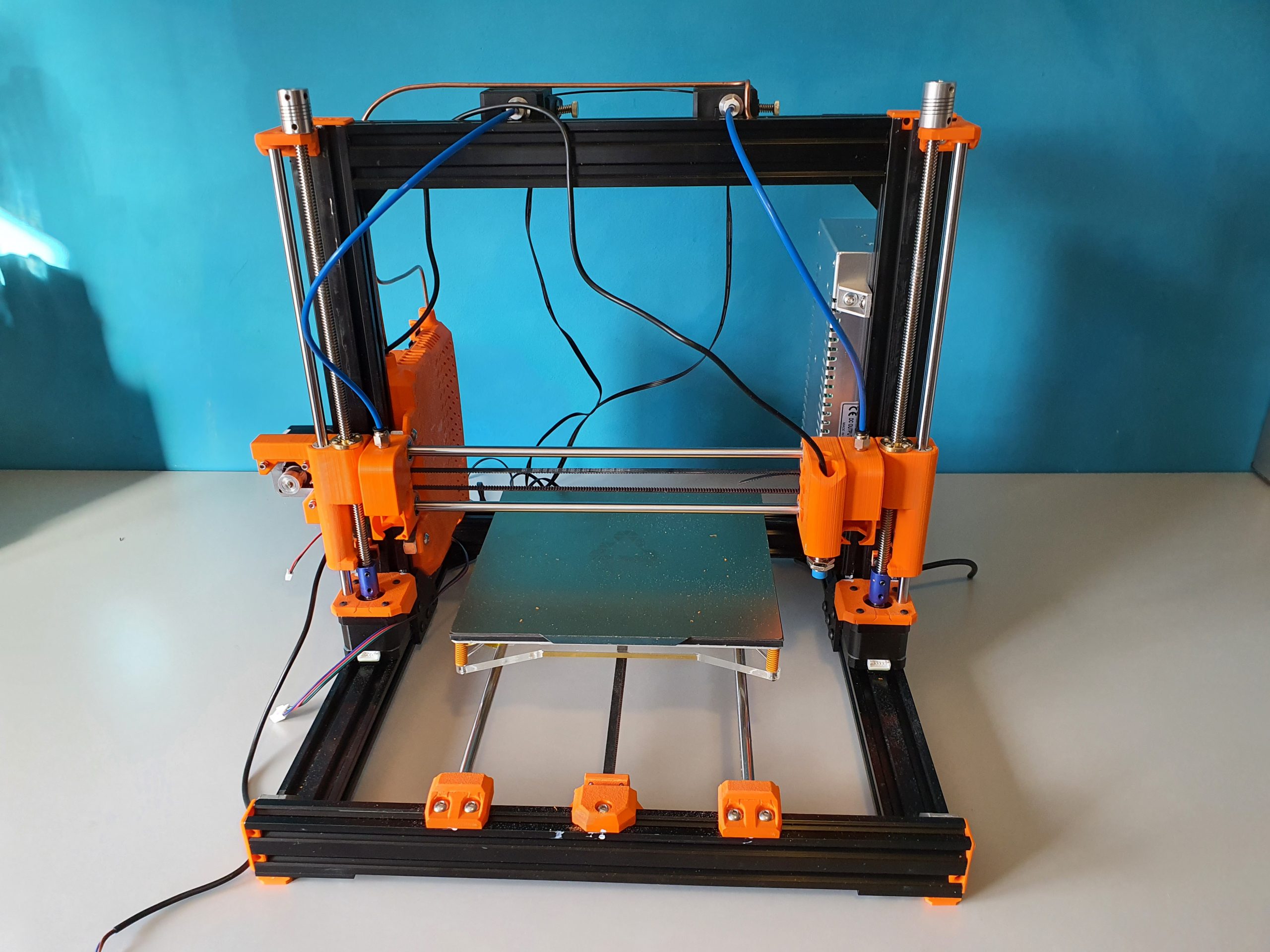
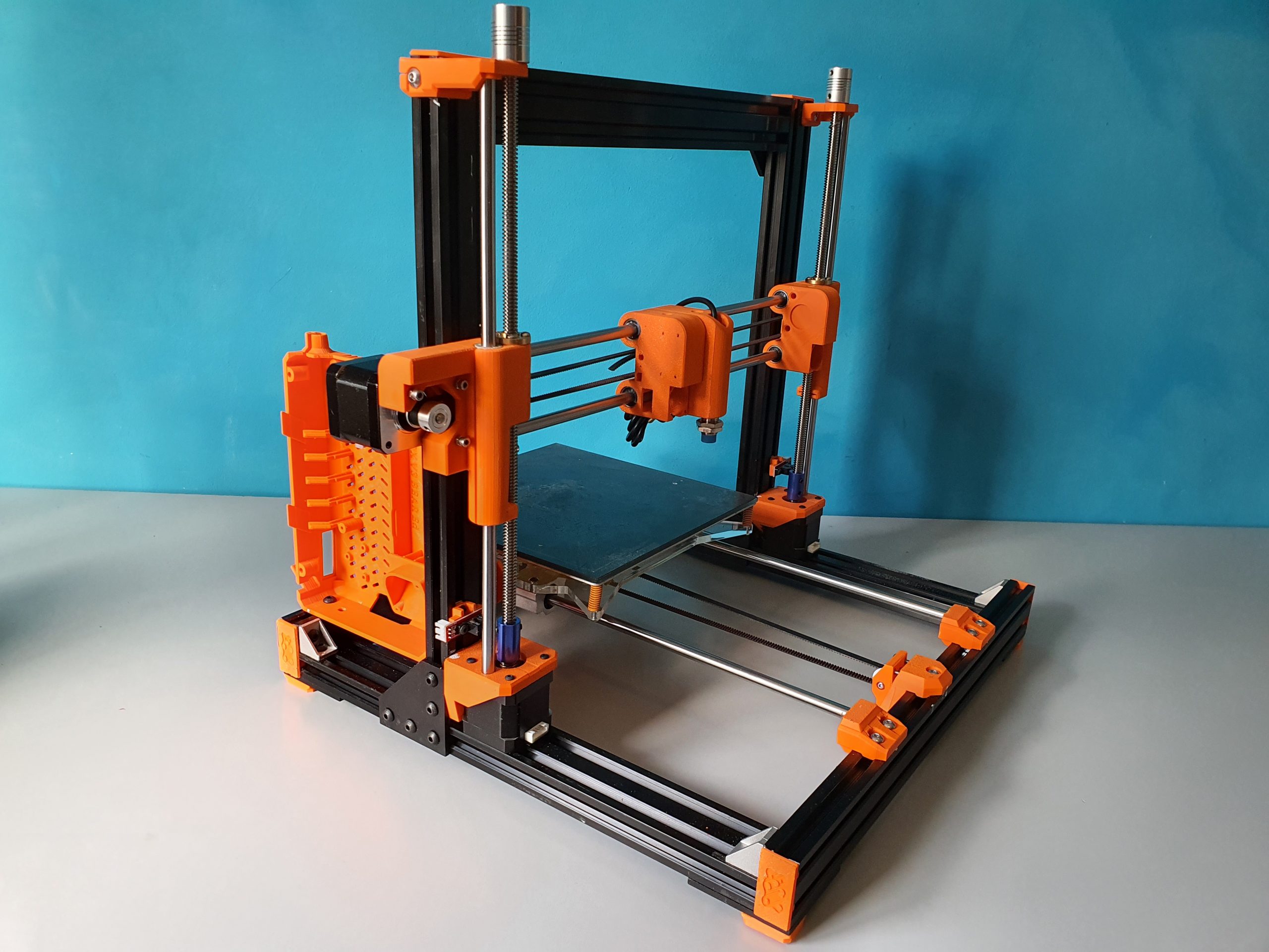
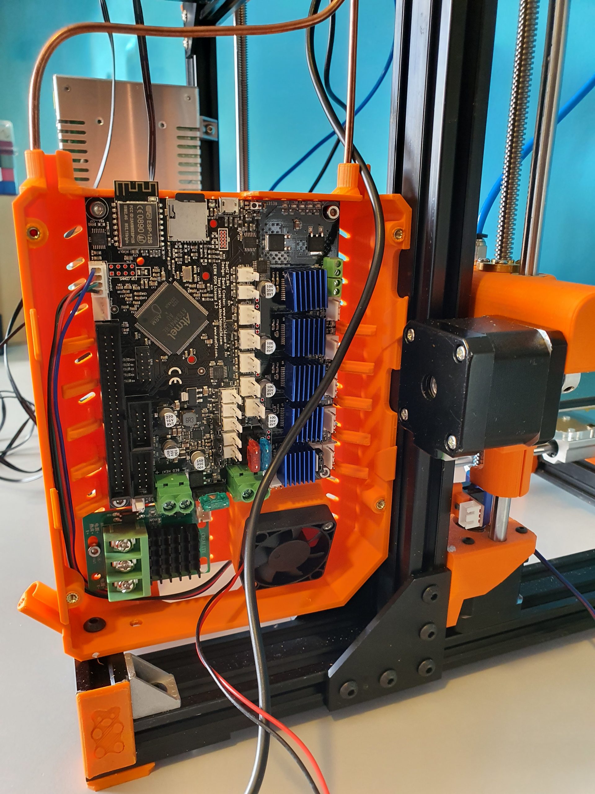
My most recent and probably last build from scratch is the dual carriage I3-based printer as shown in the below picture, in the building phase. This printer can be used either for 2 colors or for printing with soluble support PVA filament.
I decided to use sensorless homing for this build due to problems when using endstop switches. When using endstops, problems may come up because f.i. homing to the left means that the left tool will be parked against the endstop, should you use endstops. Same on the right hand side when the right hand tool is parked. I encountered difficulties that the driven sensor carriage in the middle can then get into an unknown state (or position) when both tools (carriages) are in the parked position.
If you home one of both Tools with sensorless homing, the status of the sensor carriage is always automatically known. So, since the XY position of the center (sensor) carriage is known you can always do a Z-homing at any given X-Y position and you can also do G32 and G29 without the need to carry T0 or T1 along. And- you can easlily reset an unknown status of the sensor carriage by homing it, either left or right.
Get my build plans and Configuration files for Duet2wifi HERE
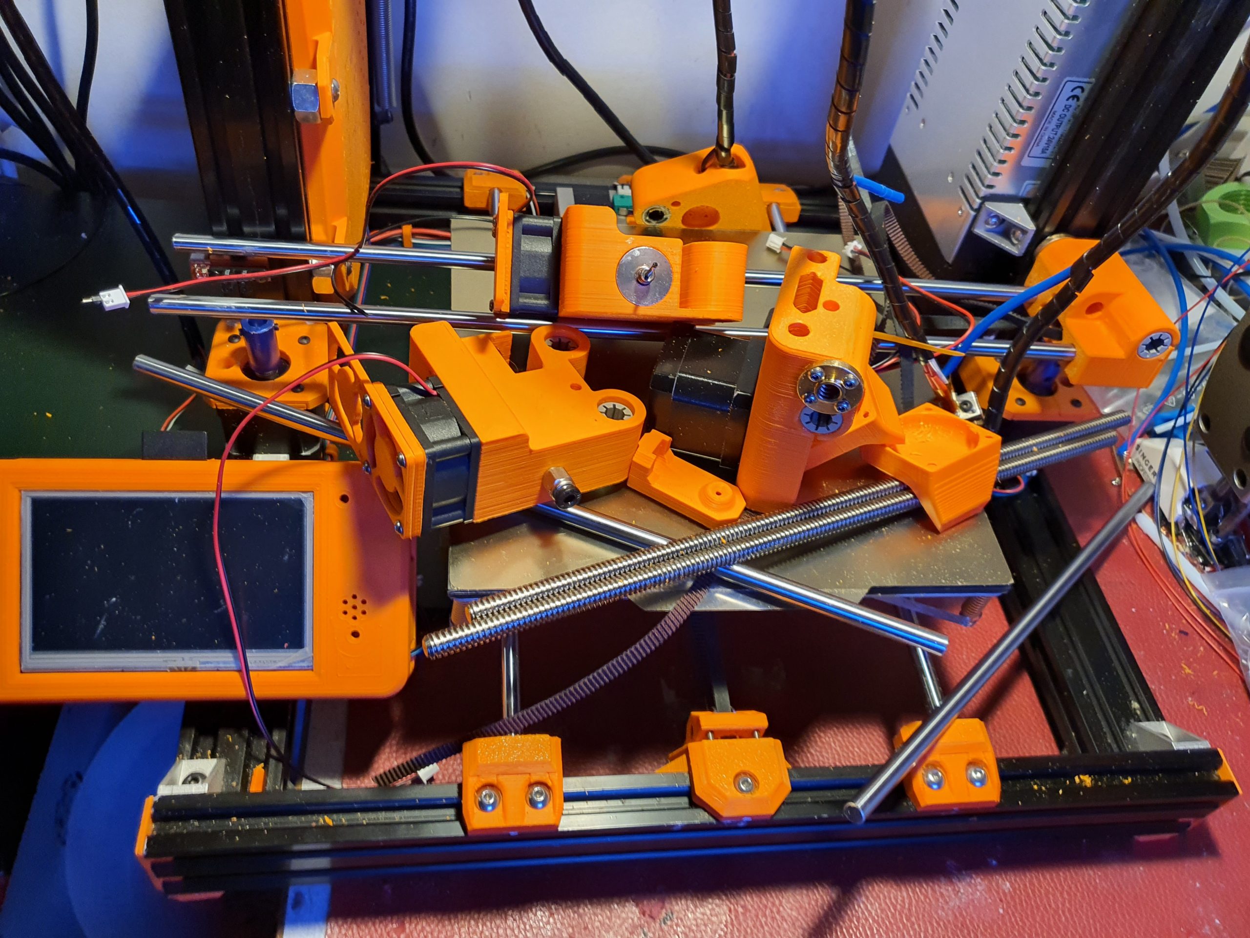
The box at the left rear is for the Duet2wifi board. The 24V fan-regulated power supply is already positioned at the rear, right side.
The main challenge with this build was to get the settings perfect for the dual tools.
It took me 2 months before I got it to work perftectly for both PLA and/or Petg.
As with my previous dual color dual nozzle builds, the basics is very simple. Just define 2 tools with 2 heaters, 2 temp sensors, 2 fans et cetera.
I already envisioned the approch with the slicer(s): All offsets are done ONLY in firmware, NOT in the slicer! As far as the slicer(s) is/are concerned, the nozzles of Tool0 and 1 are at the same (X0/Y0) offset.
For the Duet, the only addition in the slicer is an M0 command as stop command for the printer. Define 2 nozzles of 1.75mm without any offset and you’re done in the slicer.
Then, you will need to set everything in your config.g at the tool section like XYZ offset and so on.
I decided to get T0 as reference, and set everything to 0 there. X=0, Y=0 and Z=0. Then, measure the differences at T1 versus T0 with calipers to start with and inport these values in the T1 toolsection in config.g.
Start a testprint and measure what to amend, take little steps and the metrics are done!
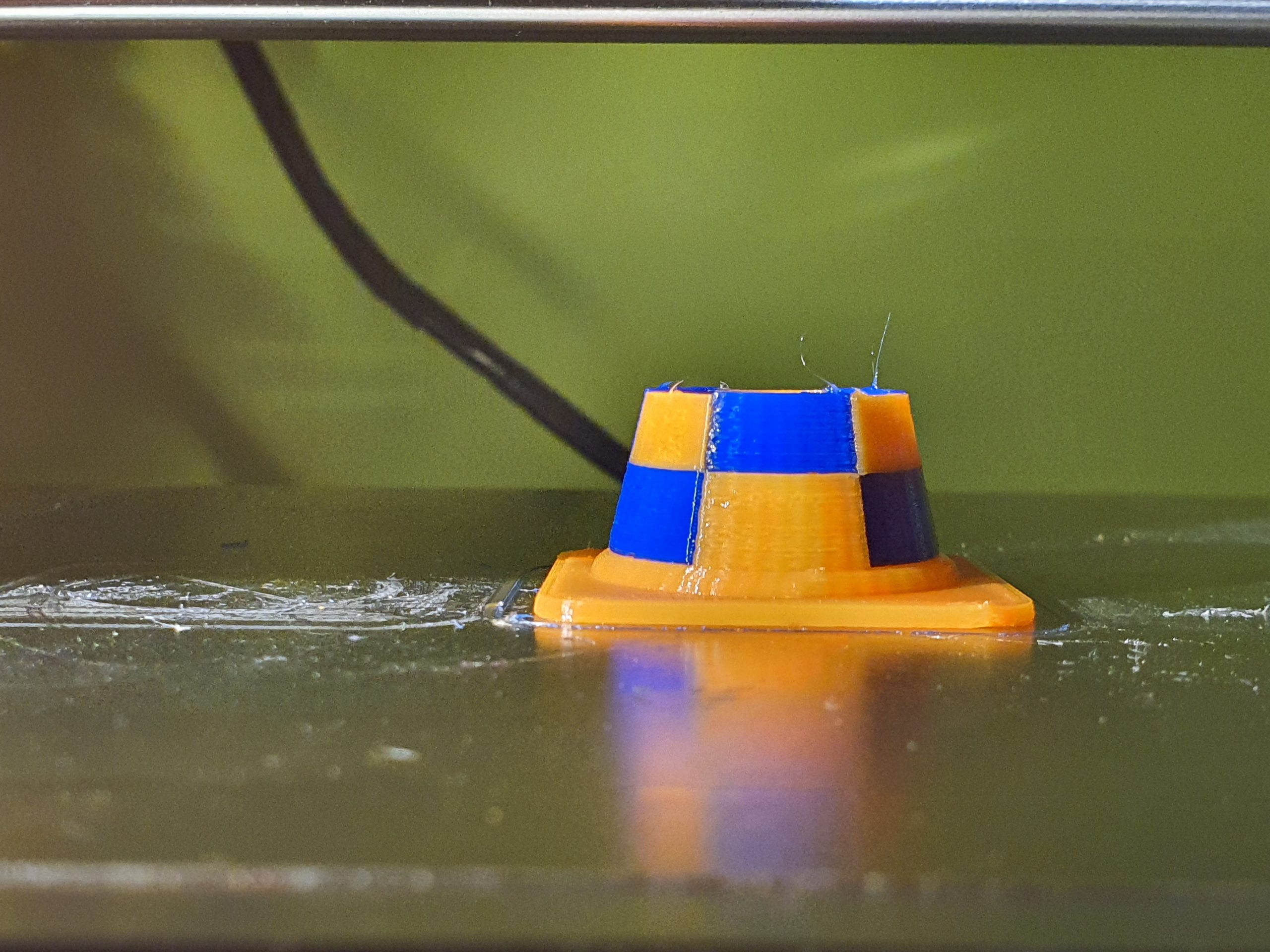
But- the hard part is- as I experienced- to get good prints without blobs and unexpected stringing, both incoming as outgoing (into and out of the printed object(s). Drying the filament also helps a lot!
In the end, I just took the same approach as with the tool settings: As little as possible retraction settings in the slicer and all except the basic print retractions are now in the configuration files that are called upon Tool changes tpre.g, tfree.g and tpost.g (for T0 and T1).
This means that you can play with retracting and extruding of filament length and speed directly at, during and after Tool changes. And- in my experience it is all affected by the type of filament you use and the temperature you are at with the hotend. Also, the fact whether you use a lower temperature during waiting has great impact.
In my experience, you should finetune the config settings for the mentioned settings per object and per type of filament.
Therefore, I decided to used this printer for only 1 goal and make the settings perfect to accomplish this goal. Right now, I have optimized this printer to print 1) PLA from 123print in the Netherlands, of a specific type and 2) PVA from the same supplier. This gives me the possibility to print complex objects with soluble supports and it works extremely well at doing this!
PM: I also added LED lights on top of the printer as an integrated feature. This makes use of a heater pin as GPIO (with a M42 P [pin] S[value intensity]) command), like the solenoids that I use to catch the carriages T0 and T1. To come from the 3.3V and max 1mA from the GPIO pin to the required 24Volts, I used small mosfet boards. All programming is done in the Duet’s config and macro files, view the below example of my stop.g file which is called from the slicer’s stop setting: M0.
; stop.g
; called when M0 (Stop) is run (e.g. when a print from SD card is cancelled)
; Also called by slicer end gcode by M0
;
M400 ; Finish move queue
M117 Cool down ; Update the LCD screen with “Cool down”
M83 ; Extruder relative mode
G1 E-2 ; Retract filament 2mm for both extruders !!
M106 S255 ; Fan at 100 to cool nozzle and bed
M104 S0 T0 ; Extruder T0 heater off
M104 S0 T1 ; Extruder T1 heater off
M140 S0 ; Bed heater off
G28 X ; Home X
M220 S100 ; Set speed factor back to 100% in case it was changed
M221 S100 ; Set extrusion factor back to 100% in case it was changed
M42 P4 S0 ; Magnet T0 off
M42 P5 S0 ; Magnet T1 off
M104 S41 T0 ; set extruder T0 to cool down
M104 S41 T1 ; set extruder T1 to cool down
;M568 R41:41 S41:41 ; set standby and active temperatures for tools 0 and 1 (or single M568 T0 R41 S41)
M116 ; wait for Tools actions as specified in above M568 instructions
G90 ; Absolute positioning
G1 Y200 ; to get objects removed easier, move bed forward
M106 P0 S0 ; Fan L object T0 off
M106 P2 S0 ; Fan R object T1 off
G28 X ; Home X
M84 ; Steppers off
M98 P/sys/ledflash.g; Perform execution of ledflash.g in specified directory
M42 P6 S0.008 ; Led light setting almost OFF
M117 Jantec=done! ; Update the LCD screen with “Jantec=done!”
G1 X5 Y5 ; Move to corner
M140 S{print_bed_temperature} ; Set bed temp
T1 ; Select extruder 1 (or 0 depending on how your printer is set up)
M104 S{print_temperature} ; Set extruder temp
M116; Wait for temperatures
Please donate $1 to my paypal account if you use (parts of) my developed materials so I can continue to share nice stuff for you to download