

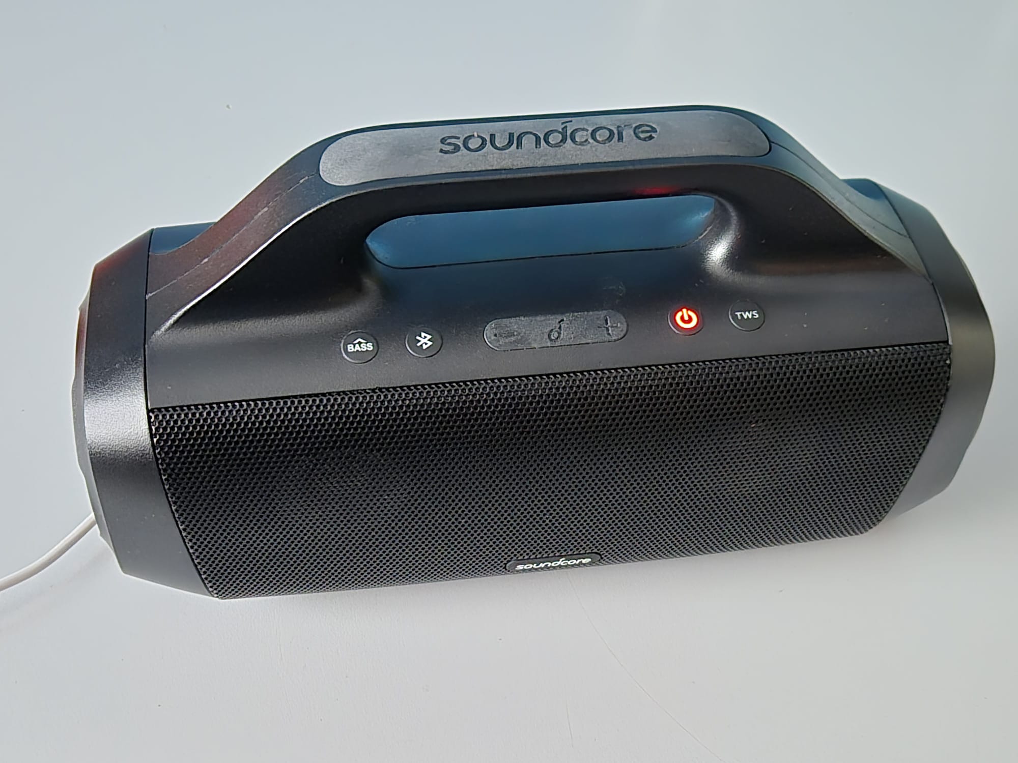
The original version of the ANKER Soundcore Motion Boom only has bluetooth IN, and obviously this is not ideal when using it for an instrument input like guitar or keyboard.
So- after some internet research, I did find a good video on how to take the motion boom apart and that’s what I did FIRST before I start this post.
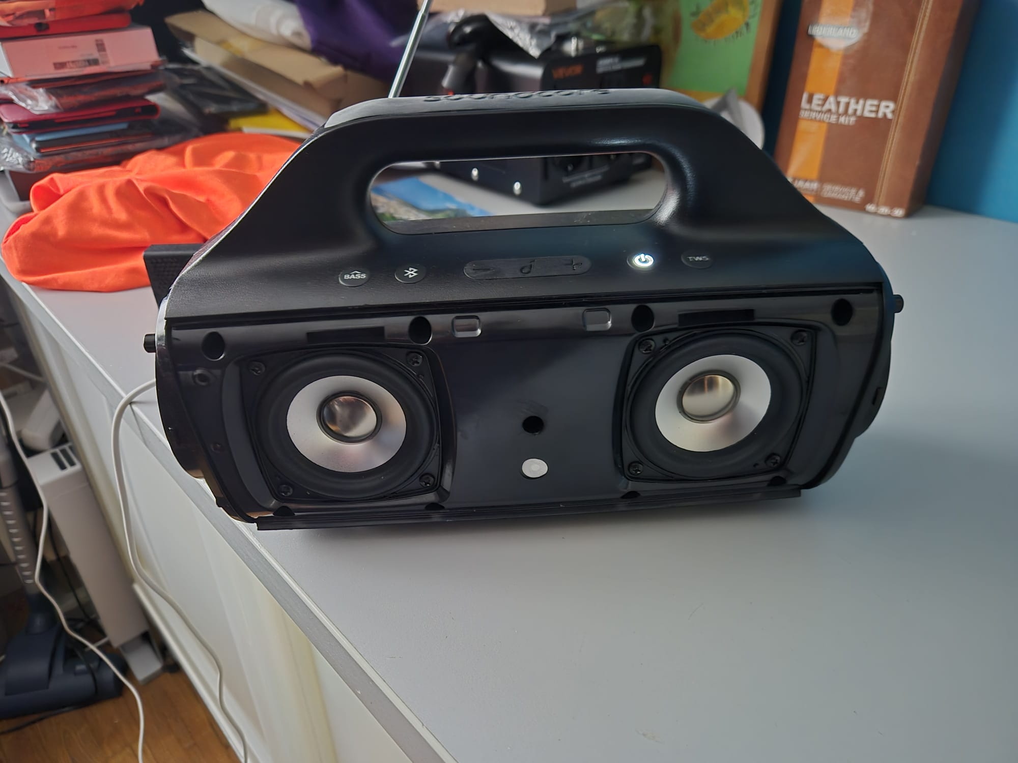
For the purpose of making the AUX-IN, it is best to just keep the speakers in the front attached with the 8 screws, instead of taking them off..
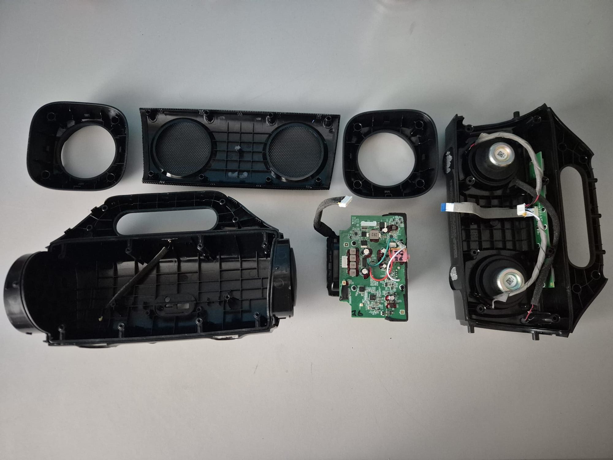
Inside the pressure box is one main printed circuit board which holds basically everything except the controls.
The controls are connected to the main circuit board with a flat flaxible pcb cable.
The BT antenna is connected with a standard mini coax conn. to the mainboard.
There is also a remote receiver at the front, also connected to the main board but with a mini 2-wire connector.
And- the battery pack is connected to the mainboard with a 7-pole connector.
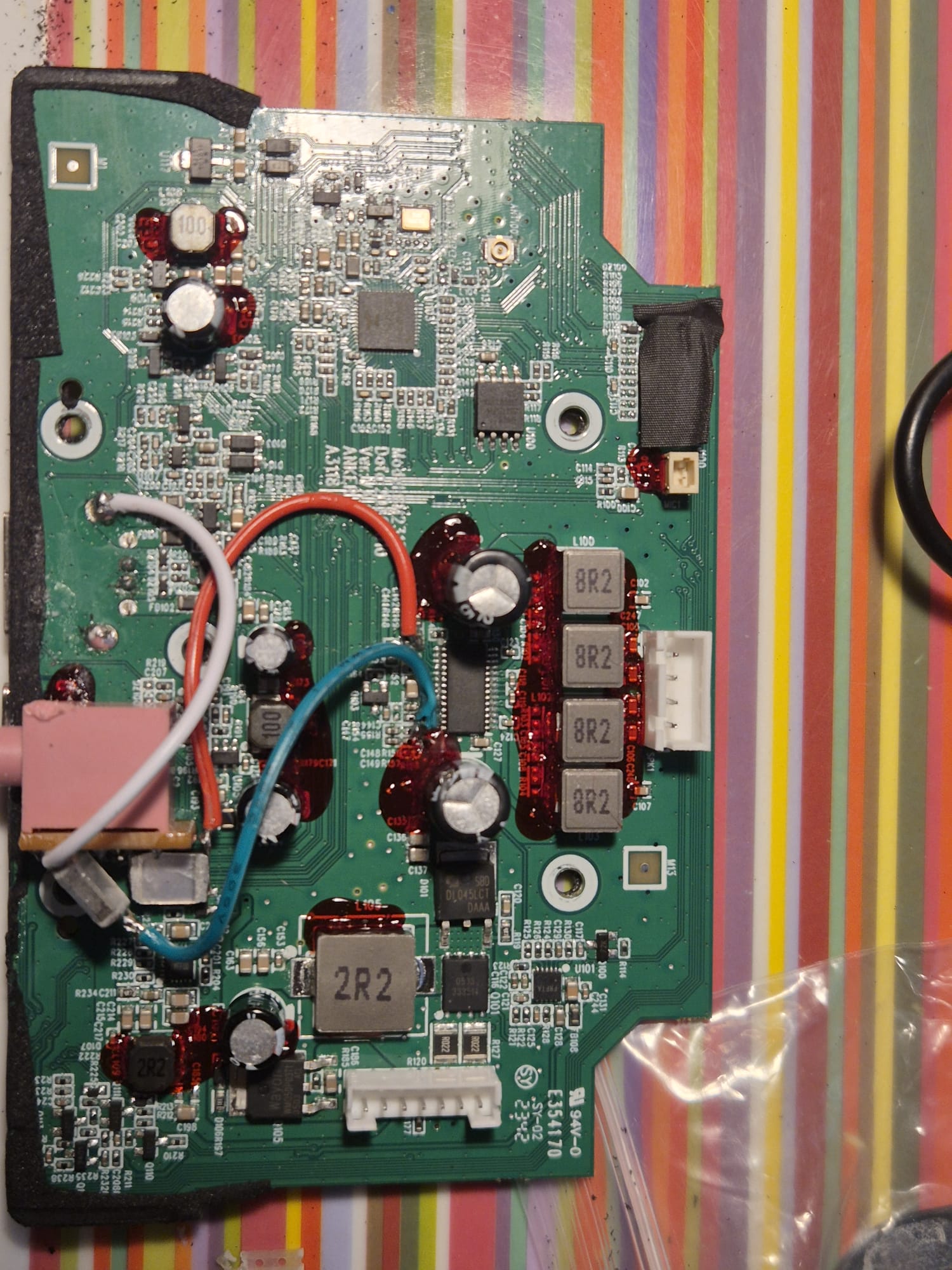
The main board has some functions which are easily identified on the board:
- Amplifier,
- Bluetooth,
- Battery charger,
- And the controls interface.
After taking the housing apart I took the main PCB and battery (in 1 piece) out.
Then, I removed the battery from the main PCB, mainly for easier handling the PCB.
I took the battery conn off as precaution, except when testing. Just to make sure nothing gets destroyed in the process.
Then:
- I connected the speakers
- Connected the controls
- Connected the battery
- Switched the device ON,
- Connected my phone via BT to play some music
- Used my Hantek scope to find the sound lines anywhere between the BT module and the amplifier.
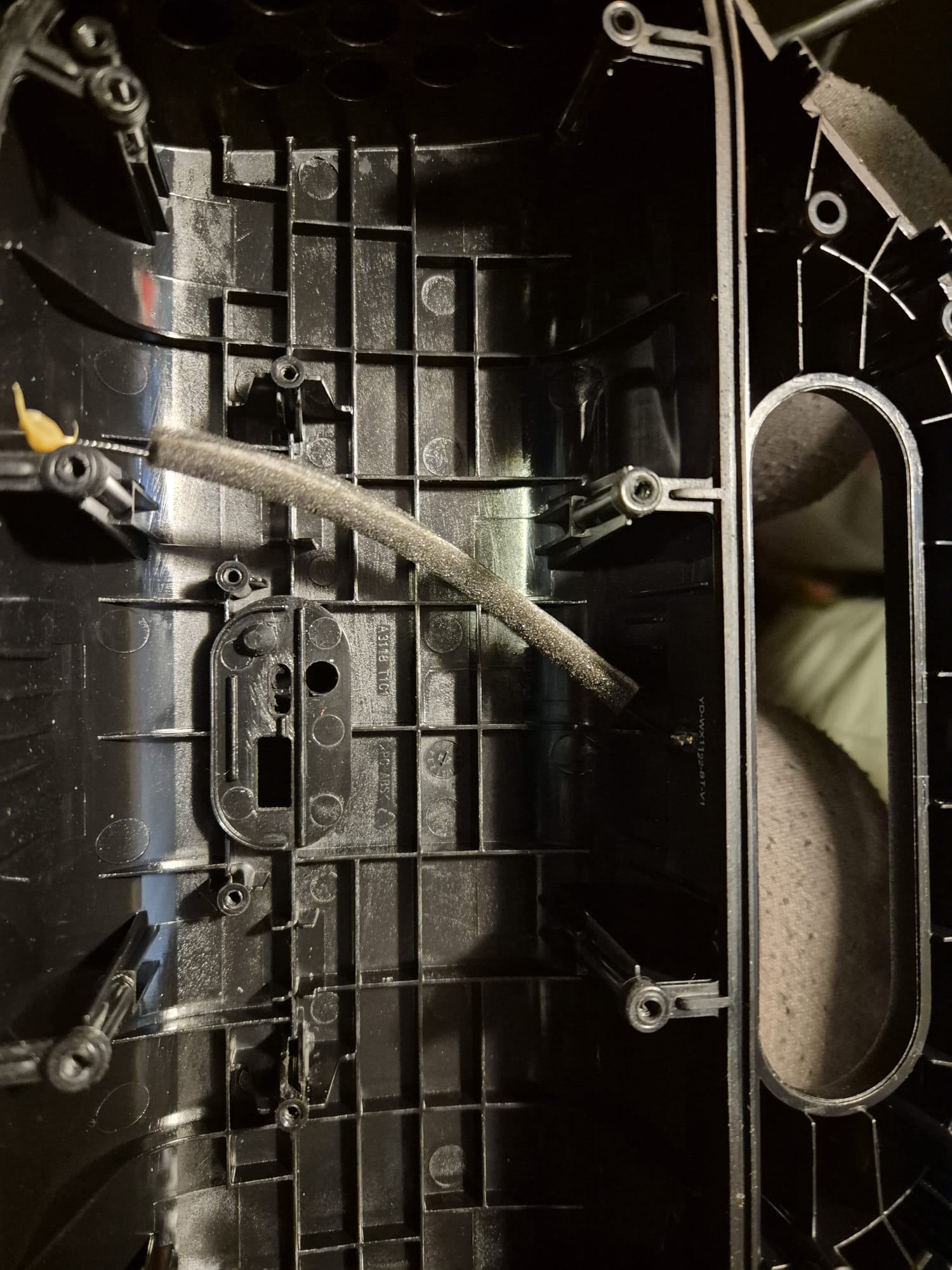
The signal-pickup points are in the area where the amplifier is situated.
In the picture, these solderings with the red and green wire are clearly visible:
White is the ground wire, from the USB-A GND to the 3.5 mm input.
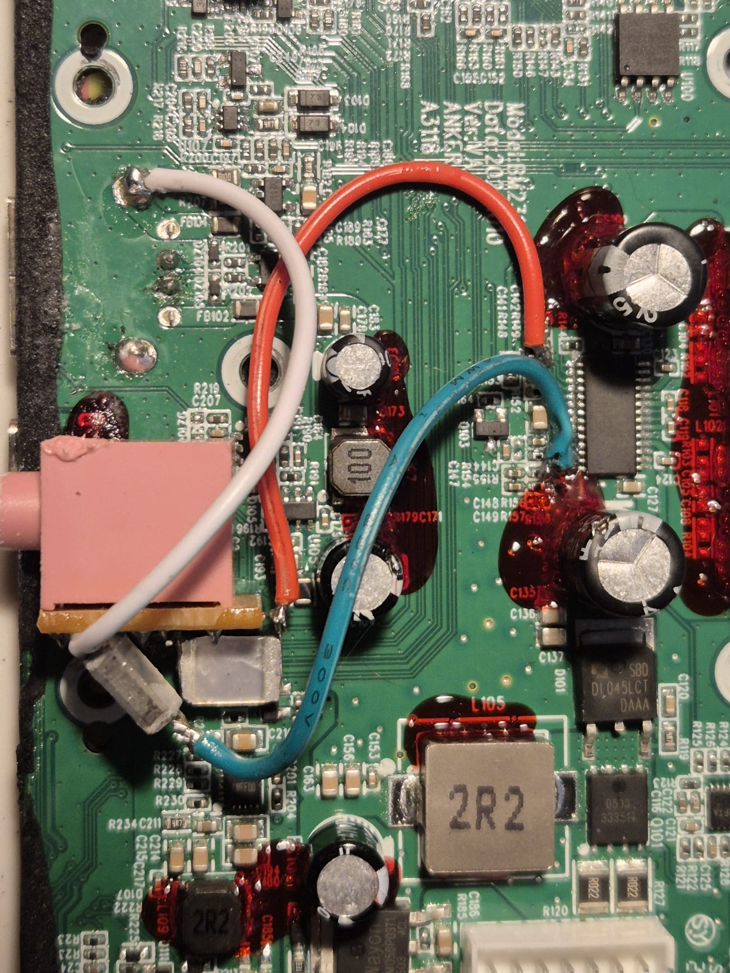
Then, I soldered the green and red wires via 100V 0.1uF condensors to the 3.5 mm mini-jack input.
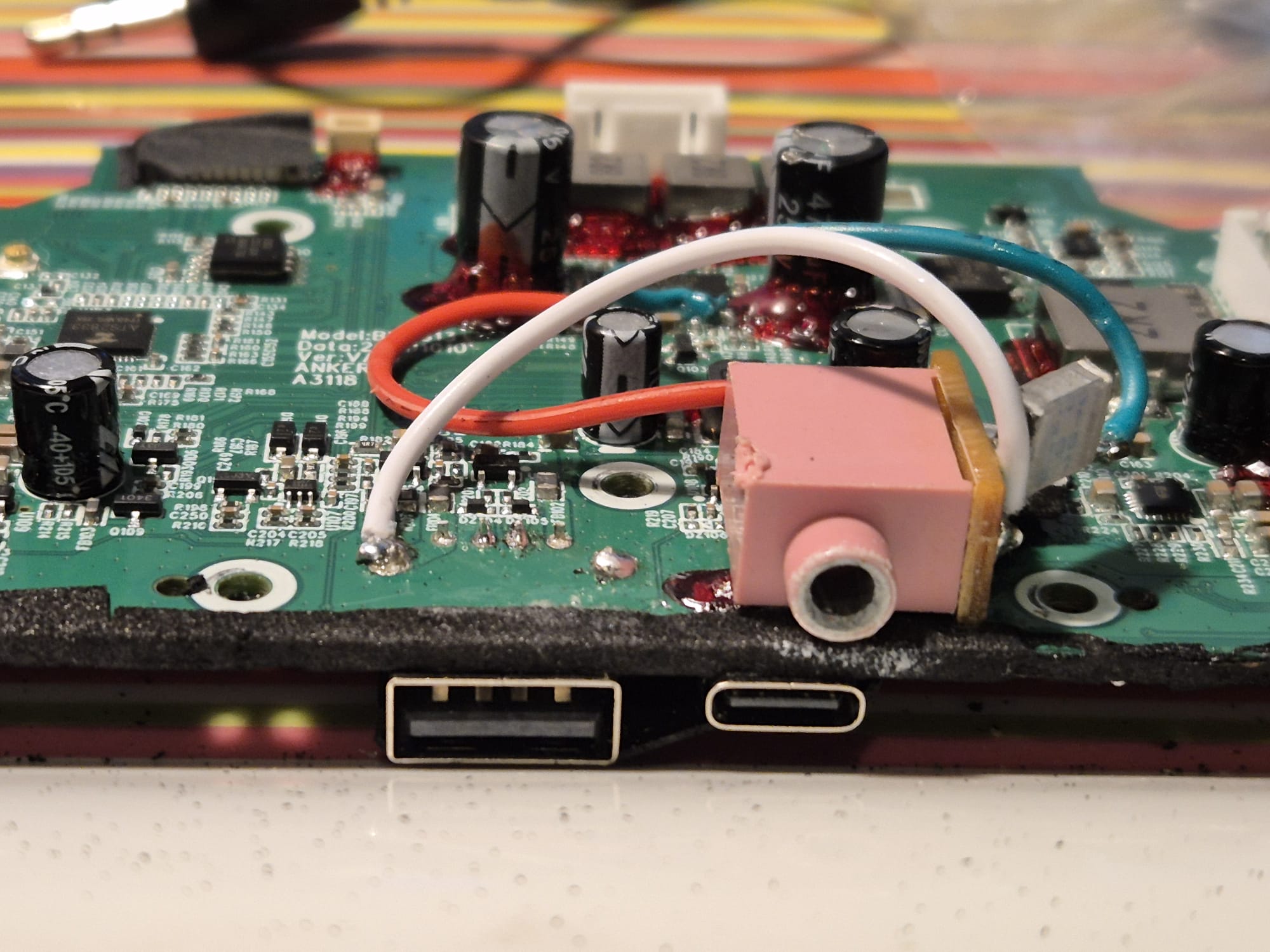
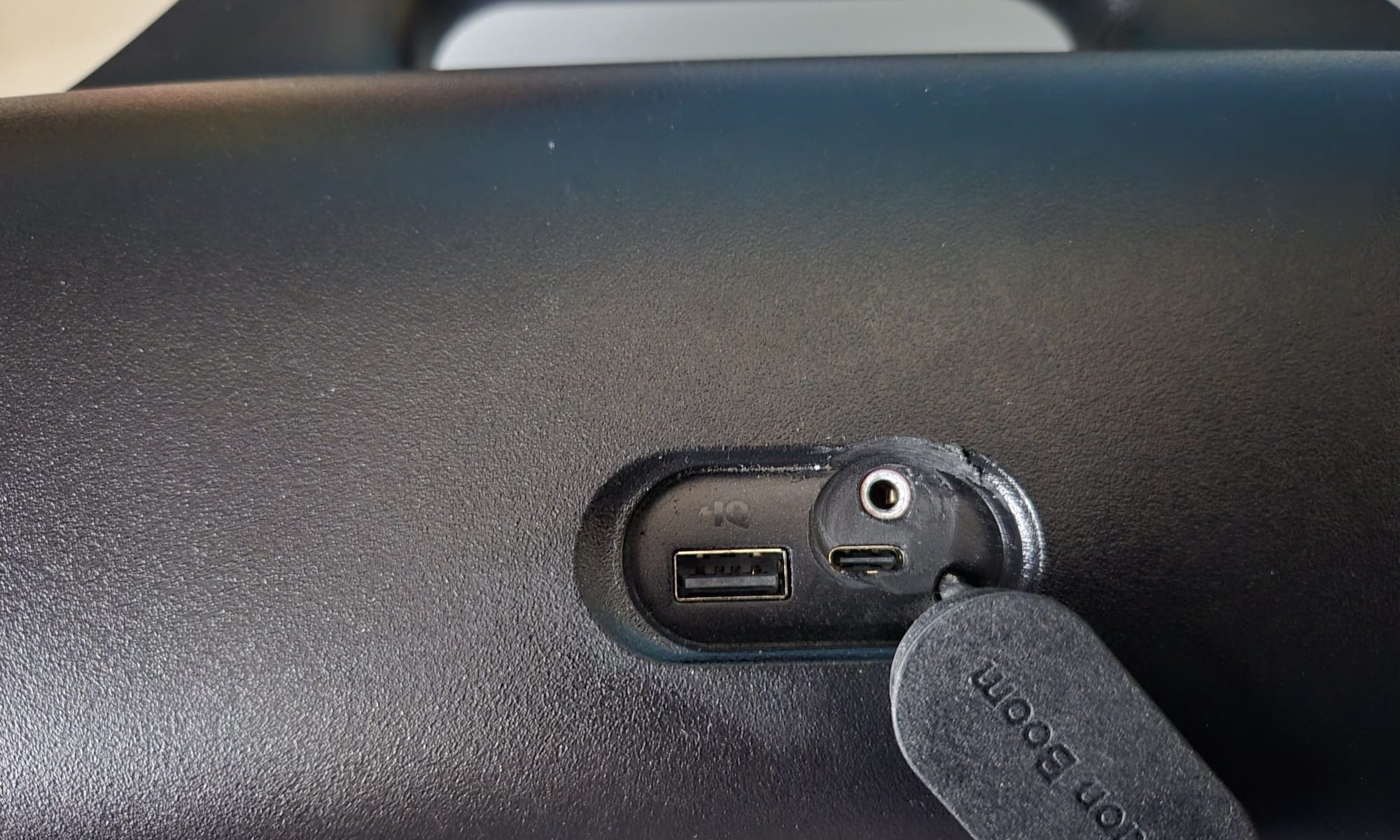
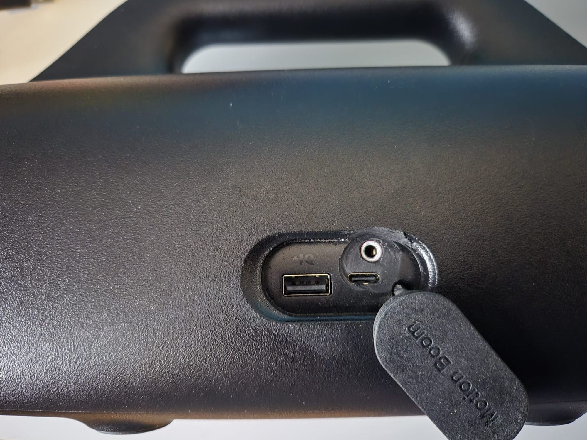
I glued the 3.5 mm mini-jack input on the PCB to stick out just above the USB_C connector. Drilled the hole, made it big enough to get a mini jack plug in there from outside and that’s it!
I also glued all solderings and the capacitors so they won’t break off since this device is meant to be used a lot. and movement might cause breaking solderings if you don’t glue them in place.
Then, I put everything together again and it’s done!
The BT module will switch off after a couple of minutes if it does not connect to anything. It is not impacting the AUX input in any way, so you can just use the AUX IN, also when BT is searching for connections.
Hope this helps you! Cheers, Jan