Concert Ukelele cheap internet kit


This is a storyboard of me building a concert ukelele based on a complete building kit of parts, and how I did this.

It may help you when you intend to go the same path.

Got me a decent local concert-sized ukelele build kit and started with putting the neck on. I first lined up the bridge, put it on the front of the ukelele’s body with tape, temporarily put the nut, centered on top of the neck and did a testfit along the neck with a straight edge. The neck needed a bit of tweaking so that the top of the frets were parallel to the top of the bridge (without the topcam).  To achieve this, I used a bit of 80 grit sandpaper on a rounded piece of wood to get some material off the neck’s fitting to the body (sand top or bottom, depending on  wether you need to get it UP or DOWN) .

Then, I glued the 2 included wooden pegs in the neck and glued the neck on the body. I used painter’s tape to prevent any damaging on the neck and body and used a big clamp to press the neck on the body.  When clamped on, I rechecked for straight mounting and adjustedb this again.

The trick to get this correct is: Use painter’s tape on the front of the ukelele’s body and make a line in the center with a pencil. This line must be in line with the center of the neck.  On the neck, you will also need a piece of painter’s tape with a center line to work well.

After proper drying, I positioned the fretboard on to the neck and glued this on. I used a block of wood as press spreader on top of the fretboard an clamped it on the neck with 4 clamps.

Then, after proper drying, I made the shape of the neck fit the fretboard by shaving the neck off.  After this, the neck was sanded down by hand from 40-80-160 and 400 grit. Finally, i taped everything except the neck’s rear and except  the head’s front and rear. I sprayed 5 coats of synthetic 1-stage acrylic clearcoat.

Next was spraypainting the body.

I sanded all of the body with 180 grit to get the factory-primer off. Then I taped all of the neck off, as well as the rear of the body AND I also taped off the exact space that will be occupied by the bridge, so later on I can glue the bridge on the front wood by removing this piece of painter’s tape.

Then, I  put a double coat of medium grey acrylic paint on the front and sides of the body since this will be sprayed later with color and needs to be smooth for my special paint effects. I first sprayed the back with 2 layers of gold/bronze paint. Then, I taped the rear body part off.

Now, after sanding the primer with grit 600, the special paint front and rear of the body will go on. First, I sprayed 2 layers of chrome color on the body’s front and sides. After 2 minutes, I sprayed black on the corner face between the front and sides. Directly after this, I used a clean felt cloth dipped in thinner and smoothed out the black edges all over the chrome surfaces. This caused a kind of special effect that resembles marble, only the color is silver/aluminium-like.

After a couple of minutes I took off all of the painter’s tape from the  taped-off parts EXCEPT the bridge tape-off AND except the fretboard tape-off.

After this, I had the ukelele drying/hardening for 3 days in the sun-heated garden shed.

Finally, I put 3 coats of acrylic clearcoat on neck and body.

After 5 minutes I removed the fretboard tape-off.

After 2 hours of drying I repositioned the bridge on the front of the body, glued it on at the right position with a drop of superglue and then, I carefully cut around the bridge to remove the painter’s tape and all lacquer that sits on top of the tape.

After this, I put the bridge on its place and drilled the 2 holes to screw in the bridge, put woodglue on both surfaces, and fastened the bridge with the 2 screws into the front of the body.  I immediately cleaned off all woodglue that squeezed out with a damp soft cloth, since the paint is still quite soft at this point in time. Then, I put in the 2 little round pieces that fit in the screwholes. I used woodglue to retain it properly.

I let it all dry for 2 days.

Now, it is time to put in the tuners, the nut and the bridge’s top cam.

I had to drill the 4 tuner holes a bit better at the top side of the neck, because the little push-in reainers did not go in. After this, I pressed the 4 push-in retainers in and drilled the holes for the tuners at the rear of the neck’s top.

The nut must be glued in, at the top of the freatboard. I sanded the place to glue the nut with a piece of 80 grit and gled the nut with woodglue whle holding it in place with a small clamp.

Then I put on the strings, and filed the topcam’s grooves for the strings so they are at 0.3mm above the first fret which I like as best position for easy playablility.

I had to lower the delivered bridge’s topcam with 2.6mm to get the best playable position of the strings above the lower frets.

Then, I started tuning the ukelele.  This proved to be the most difficult part for me since I had stringed the instrument incorrect. When delivering the instrument to the user, I found out that the thickest string is nit the top string like I am used to, but that the 2 topstrings are inverted for use on a uelele. After switching thes 2 strings and retuning, it was allright. Pff!

Below are some pictures of the ukelele, during the process of building it. Hope this may help new builders! Cheers, jan

Building a ministrat electric guitar

The final result

Why would you want to build a ministrat?

Well, I wanted to have an electric guitar that I can take along easily when I travel.

Plus, I want to use my leftovers from previous builds for this.

So- I will re-use my ministar semi-acoustic precticing guitar’s neck and join it with a very lightweight basewood strat body that I did not yet use for a guitar build.

In the end, it was a very satisfying build because everything came together very well. And- the guitar is very well playable.

Please enjoy my build by watching this post!

the body’s rough planned cutout lines. This also shows how the pickguard had to be reworked
I had to use mini pots due to size restrictions of the rebuild, so the Fleor big pots -and switch- will be re-used for something else
Nicely cutoff the right hand lower bottom of the pick guard and replaced the 2 right hand side pots to get it all to fit within the smaller available space. Also, made a new mounting hole for the pickguard, next to the RH pot
After the body’s rough cutout: Right from the bandsaw, both the pickguard and the remaining part of the body.  Unfortunately, 2 holes need to be filled.,
need to plug 2 holes
and need some work at the oscillating sanding machine
trying fitment of the ministar neck with the neck’s cutoff. This obviously does not fit, and rework at the neck’s width and height is required to get it ot fit in the body’s neck pocket
the neck and the rough cutoff on the bandsaw., Later I routed the neck to fit the body’s neckpocket at 19.2mm thickness (height)
the 2 jigs I made to level the neck at fret 12 and fret7 while cutting the fitment of the neck in the body’s neck pocket to 19.2mm…
first fitting the ministar’s neck on the reworked stat body
had to finally build me a proper router table for the neck and for the body edges
both sides of the body has been rounded. I first made the body side curves smooth with my oscillating tube sander, forgot to make any pictures, though
the neck has been mounted semi-fixed with screws and a couple of drops superglue. Left the detachable extender is shown that will be mounted to the body with some screws if it is in use. The extender/attachment is made from the body’s  offcut. First, I put 3 layers of wood impregnant sealer on the wood.
the mini body only weighs 480 grams. Later I removed some more flesh between the pickups, so I can slide the loaded pickup guard under the fretboard a bit easier.
the finished guitar body and mounted neck with loaded pickguard, and the bridge. Nothing is fixed yet but all has been made to fit and to be mounted at the appropriate positions. I am making the body and extension piece bronze with shellac. This takes some time and I do take my time here.
After the 3 layers of sealant were dry, I sanded with 180 grit and started the 3 bronze tinted shellac layers. Final 2 layers I put on a bit thicker transparant shellac.

Drilled the holes, made recess pockets and mounted 2 M6 threaded inserts for the through-bolts of the add-on sidepiece. Still not decided wether I will use bolts with a fly head or leave it as is, with the allen key bolt heads
I put copper shielding foil in as well in the wood cavities as under the pickquard, before mounting the electronics
glued the nut back to the adjustable steel holder plate
2 springs are enough for the tremelo, I also grounded the spring’s end holder

Flat on the table, still without any strings. The jack output is placed in the round curved wood at the right, near the right sound potmeter
Shown with the attachment mounted at at the left. When placing the strings, I also adjusted the nut- and bridge height to 1.7m mm string height vs top of fret 12. And- also adjusted the bridge strings length for correct intonation. Apparantly I measured everything correctly and the neck is mounted at the correct position.
And just as the ministrat, no attachment needed?  Still looking for a case or bag that can hold the guitar and the separate attachment. The required inside size is 25 cm wide, 7 cm high and 85 cm long…

Here the ministrat build is almost done, but some gold colored parts were still in transit… could not wait to play and do some settings like the nut and string settings by filing the nut recesses ..
Total weight: just under 2 kilograms

I changed out the creme colored pickup covers with the gold colored ones I had ordered. And I cleaned the neck a bit better from the leftover residues of glue and tape.  I had problems with the thinnest string when mounting this. It just snapped when winding it. And I do know you need to do this in stages, first a bit of tension, wait some minutes and then, in 2 or 3 steps go to the final required tension. So I forgot to do that and I had to scavange (again) a fresh set of medium strength strings for just the replacement. Meanwhile, I ordered me a 10-pack of cheap 0.009 inch strings to carry on the activities…

Also, I exchanged all other remaining chromed parts with gold colored ones. (all screws, strap pegs, signal out connector, extension piece mounting screws, tuners, bridge and rear neck mounting plate).

I had quite some issues finding the best fitting gold colored tuners for the ministrat. Finally, I fount and bought the ones that have metal knobs that are small enough not to hit the in-between knob when tuning.
I designed and 3d-printed this rear tremelo cover for the ministrat, and spraypainted it to look old and imho really fits the ministrat.
The M6 threadd inserts on the side have been gold colored to match the ministrat’s design
also, the signal output got cold colored

NECK’s ORIGIN

For reference, the ministar portable guitar I had once bought (in 2022 ?) had a piëzo element placed under the plastic bridge and needed an internal amplifier to get some sort of usable volume output. And that required a battery in the guitar’s lower hollow foot. I never really used this guitar, due to the fact that it came with steel attachment rods that are very heavy and didn’t give me a kind of guitar feeling.. And it was bulky/heavy underway. The ministar model I have used as neck donor to make my new ministrat  was similar to this model:


:


Adding AUX-INPUT to original ANKER Soundcore Motion Boom

The original version of the ANKER Soundcore Motion Boom only has bluetooth IN, and obviously this is not ideal when using it for an instrument input like guitar or keyboard.

So- after some internet research, I did find a  good video on how to take the motion boom apart and that’s what I did FIRST before I start this post.

For the purpose of making the AUX-IN, it is best to just keep the speakers in the front attached with the 8 screws, instead of taking them off..

Inside the pressure box is one main printed circuit board which holds basically everything except the controls.

The controls are connected to the main circuit board with a flat flaxible pcb cable.

The BT antenna is connected with a standard mini coax conn. to the mainboard.

There is also a remote receiver at the front, also connected to the main board but with a mini 2-wire connector.

And- the battery pack is connected to the mainboard with a 7-pole connector.

The main board has some functions which are easily identified on the board:

  • Amplifier,
  • Bluetooth,
  • Battery charger,
  • And the controls interface.

After taking the housing apart I took the main PCB and battery (in 1 piece) out.

Then, I removed the battery from the main PCB, mainly for easier handling the PCB.

I took the battery conn off as precaution, except when testing. Just to make sure nothing gets destroyed in the process.

Then:

  • I connected the speakers
  • Connected the controls
  • Connected the battery
  • Switched the device ON,
  • Connected my phone via BT to play some music
  • Used my Hantek scope to find the sound lines anywhere between the BT module and the amplifier.

The signal-pickup points are in the area where the amplifier is situated.

In the picture, these solderings with the red and green wire are clearly visible:

White is the ground wire, from the USB-A GND to the 3.5 mm input.

Then, I soldered the green and red wires via 100V 0.1uF condensors to the 3.5 mm mini-jack input.

I glued the 3.5 mm mini-jack input on the PCB to stick out just above the USB_C connector. Drilled the hole, made it big enough to get a mini jack plug in there from outside and that’s it!

I also glued all solderings and the capacitors so they won’t break off since this device is meant to be used a lot. and movement might cause breaking solderings if you don’t glue them in place.

Then, I put everything together again and it’s done!

The BT module will switch off after a couple of minutes if it does not connect to anything. It is not impacting the AUX input in any way, so you can just use the AUX IN, also when BT is searching for connections.

Hope this helps you! Cheers, Jan

Wolfang GA200 action camera mini rig STL download

Wolfang_GA200_4k_videocam_smallrig_20260318_V11G_jantec.nl


Please donate $1 to my paypal account if you use this original jantec.nl design  -)

Printed on Voron 600 @ 0.3 mm LH and 0,8mm nozzle, transparant PETG. Hispeed in 1 hour at 100% infill, front down, brim 0.2 mm thick, 10mm wide. Supports everywhere in matrix mode @ 10mm wide, big gap 0.5mm top of Z and 1.2 mm on X/Y spacing. Temp 235 deg nozzle, 85 deg bed. 100% fan except for 1st 3 layers.

STL download acoustic guitar string tuners plastic pegs repair with 3d printed covers

One of my very old DIY elktro-acoustic guiters had broken tuners on it. I did not want to order me new ones, since the mechanics were Ok, it was just the plastic covers that were all more or less torn up.

In Openscad, I designed the to be 3d-printed sleeves that fit around the metal tuner shafts.

acoustic_old_guitar_tuner_plastic _replacement_part_5.9mmID_10mmOD_30mmL_V3_20260305

I printed 6 sleeves in transparant PETG on the Voron 600 (0.8 mm nozzle, 0.3mmLH, 235deg nozzle//85deg bed.

No supports, although I did use a firm brim around the shaft.  I printed the sleeves one at a time, in 7 minutes each.

The old shafts were tapped out of the metallic shafts. I used my vice and opened the vice’s jaws just enough to tap the shafts out of the sleeves.

Mounting the sleeves around the shafts is pretty easy, since the hole in the shafts and sleeves can be lined up due to the transparancy of the PETG material.

The shafts fit easily in the sleeves, although I used the vice to push the shaft in for the last 1-2 cm, due to the tight fit of the shaft in the inner sleeve’s recess that makes the sleeve follow the circular motion of the shafts when tuning the strings.

When installing the tuner sets, I used some vaseline around the plastic sleeves where they meet the holes in the tailstock wood so the sleeves don’t get stuck.

The process of de mounting and mounting the sleeves and the tuner sets is pretty self-expalinatory, please have a look at the below added photo’s!

BTW, I made 2 versions of the sleeves.

The one I used on my fast Voron600 is a bit wider inside (shaft diameter +0.4mm) .

This is needed due to the fact that little holes are always printed smaller on my Voron600 with the 0.8mm nozzle  than designed.

If you want to print the sleeves with an accurate 3d printer, the exact fitting design is HERE:  acoustic_old_guitar_tuner_plastic _replacement_part_5.6mmID_10mmOD_30mmL_V3_20260305

My newly acquired Corghi A2001S tyre exchanger

Picked up yesterday (Monday, January 13, 2026) in Barneveld (The Netherlands, Europe): A well-used Corghi tire changer for the wheels and tires of classic cars.

This machine can handle rims up to 18 inches in diameter, and with the extension pieces, up to 22 inches—more than enough for my needs.

In addition, the vertical column can be tilted backward, which is very convenient once you’ve set everything up and are moving on to the next wheel of the same size.

Of course, there are a few flaws, as you’d expect from a machine that’s been in use for quite a few years.

The machine is now mounted on sturdy wheels so I can move it and put it out of the way when I’m not using it.

Yesterday I went ahead and hooked up the power and air lines right away and tested everything out: It all works! This version has 3 foot pedals, and you can manually move the column back and forth, which works pretty smoothly.

After installing the air regulators and the air compressor for the air system, I mounted my winter/all-weather tires for the Atto3 onto the LM rims I scored on Marktplaats, which still had tires that were way too big (for a Mazda CX-9) still on them. First, I had to remove those big tires that were on the rims (see photo above), install the TPMS sensors, and put the new tires on! After balancing them, I managed to hit the road this winter with M&S tires just in the nick of time!

Next, I’m going to use the machine to change the tires on my 1970 Citroën DS convertible. It currently has 15-inch Kenda winter tires on it, but I’d actually prefer to have the original Michelin X-as tires on it—they just drive better. And since I’m no longer taking the DS on winter sports trips like I used to, it’s better to take those winter tires off anyway.

Now—the reason I bought the tire changer: I’ve had a lot of trouble getting local tire shops to change and balance the tires on my Citroën Traction Avant and DS. It’s been a real hassle. With the DS, for example, there was a lot of balancing weight in the rim flange after the Kenda all-weather tires were installed, which meant the wheel covers could no longer be centered. It looked really ugly.

So a few years ago, I bought a wheel balancer with an adapter for old rims (which don’t have a center hole). I’ve gained a lot of experience using it on both my classic cars and my other vehicles.

PLEASE NOTE: The balancing weight is in the top-left corner!

This allows me to balance all rims perfectly (almost invisibly) using adhesive weights. In addition, those old rims often suffer from axial imbalance, which can’t be fixed by balancing alone. To fix that, you have to true the rim. I’ve learned how to do that as well, but I couldn’t get local tire shops to do it for me because they no longer have any experience with such old steel rims. Mounting these 5-hole rims with adapters is also quite a precise job and takes much more time than simply sliding the rims over a central axle.

Working with older rims and tubed tires doesn’t make things any easier, and it also takes time to find the correct rotation position of the outer tire on the rim/tube combination so that you have to use as little balancing weight as possible. And that’s exactly why I’ve decided to go ahead and buy a tire changer myself. That way, I can take care of all those things—like breaking the tire bead, rotating the tire, re-inflating it, and so on—all by myself.

Yeah, I know I’m a bit of a stickler. That’s why I’d rather do it myself.

DOWNLOADS:

Corghi_A2001S_PARTS

Corghi A2010_A2019_A2001S_Spanish_MANUAL

PICTURES taken directly after the purchase:  

De drukregelaar is naar binnen verhuisd en blijkbaar is de hydraulic smeerolie vernevelaar daarbij verdwenen…??
ff checken en inderdaad heb ik de grote 10 inch versie van de luchtcylinder voor de bead breaker, zoals het hoort bij de 20 inch versie!
It’s nice to see that there would be room for a fourth foot pedal. It’s a shame, though, that the original cover plate is no longer there…


Traction Avant 11BN (1955) intital repairs in 2006 and following yearly maintenance scheme

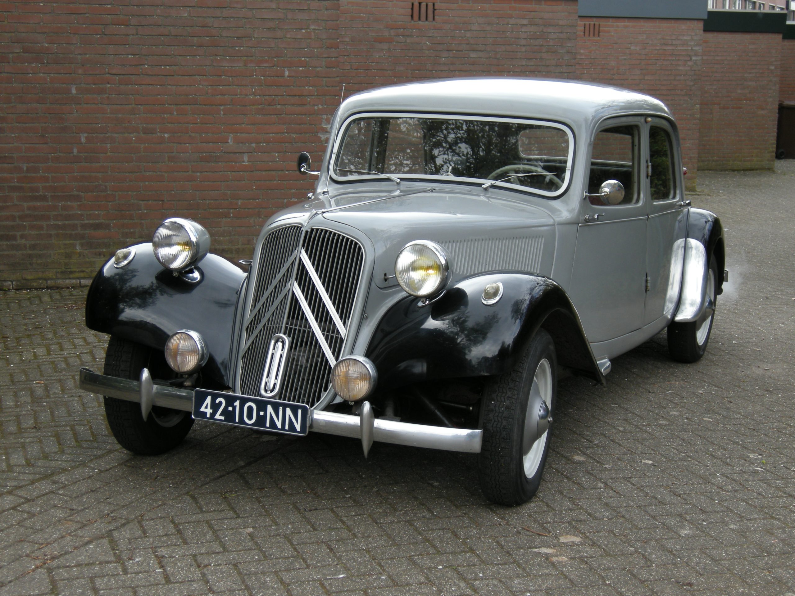
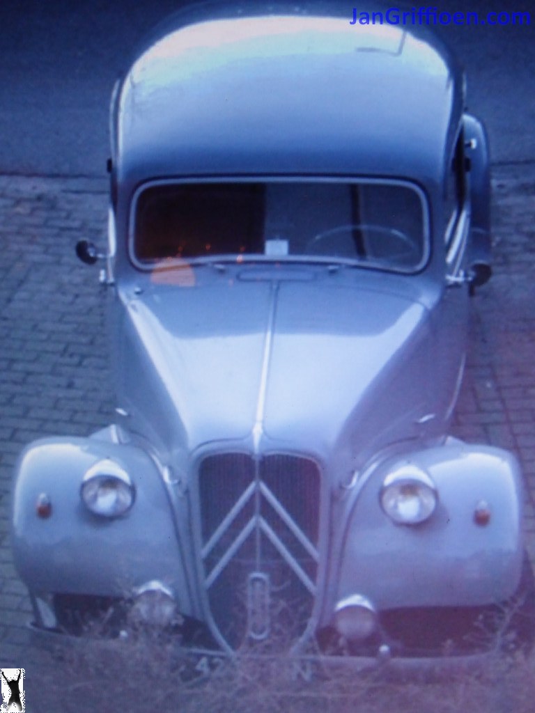
I bought my Traction Avant 11BN (1955 made) in june 2006, and I had to perform a lot of mechanical repairs before the car was roadworthy.

The engine block was cracked beyond repair, the gearbox 2nd gear was smashed, the brake system was really bad and so on.  And the fenders were  rotten in the common places. BUT- the body and the doors of the car were wonderfully intact.

AND- this car has had internal body care with either dinitrol or some other rust-preventing fluid.  Everywhere the little plastic caps show where holes were drilled to gain acces to the car’s body for the rust prevention.  One of the first things I have done is to do this process again, with solvent and rust preveting fluid, also on the bottom and underbody of the car.

Looking bad but is actually very good and solid

Other parts were also renewed: Drive axles, steering joints, all lights like blinkers, head lights, dash, interior. Also the exhaust, gas tank, suspension dampeners, horns, steering wheel (temporary until the original steering wheel was repaired)

MOT

So- to get the car through the MOT inspection I initially made the mechanics work. Later on, I also made the car’s exterior look good.  I chose to keep the internals of the car as they were, to preserve the vintage appearance.

The brakes, engine and gearbox were really bad and all had to be completely overhauled.

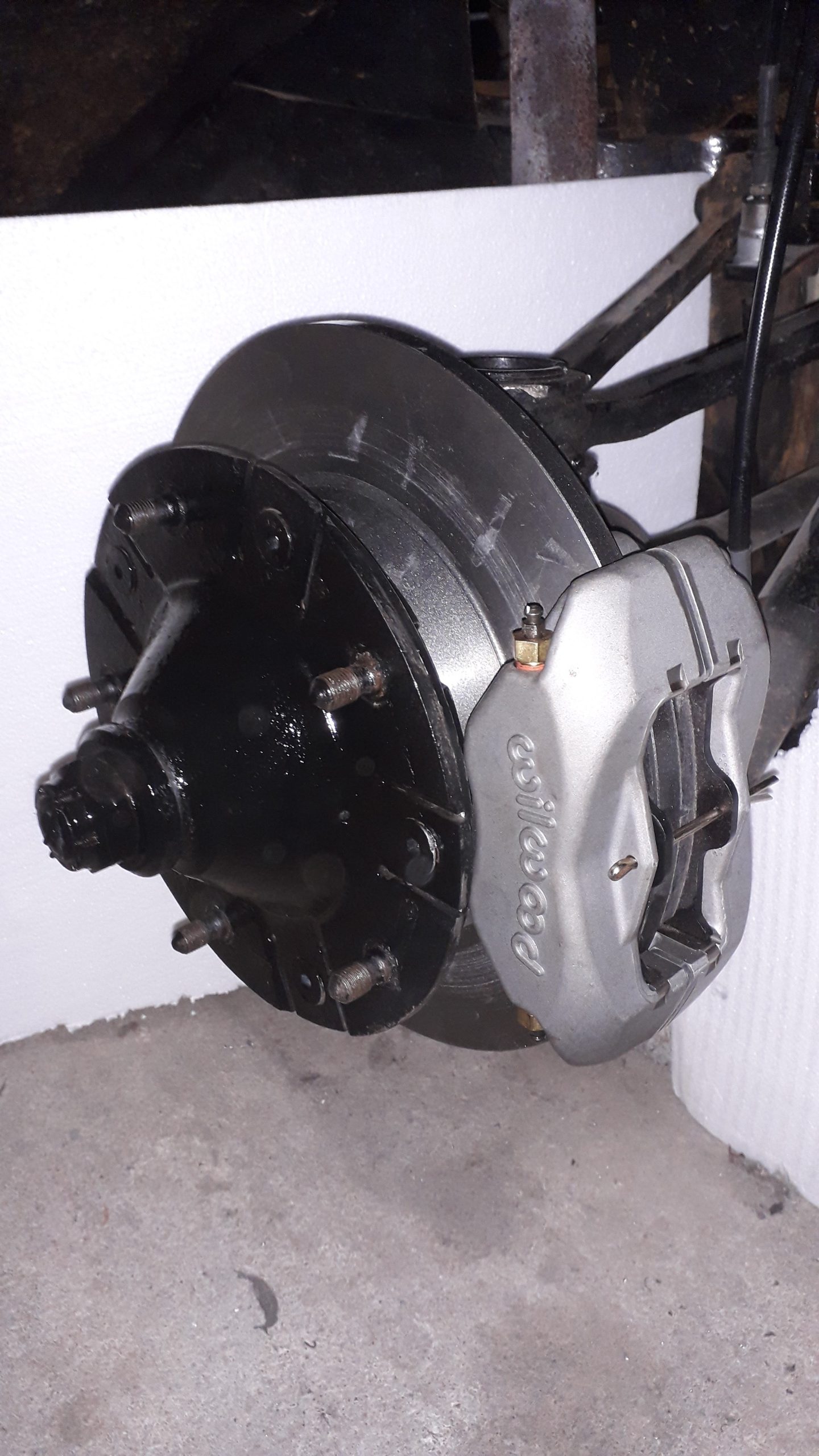
New brake calipers, new flex brake lines, overhauled master brake cylinder, changed to DOT3 brake fluid, new brake springs, new brake shoes and – retainers,  new dust covers for everything

The engine was completely seized up.  I had it soked in diesel for a week, took the carter pan off and freed the pistons. Bought a revised cylinder head and made the engine run again.  Later, I found out that the cause of the seized up engine was a cracked underblock in the passenger’s side rear corner.  But- the engine  ran well again to get through the MOT.

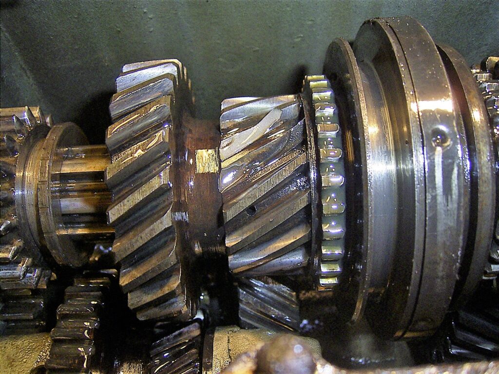
The gear box of this car is a 3-speed, no synchro on 1st gear.  It is a gearbox that is not regarded to be very sturdy and thia was my problem. Obviously, the previous owner tried to get the seized engine free by towing it in 2d gear.  2 teeth were broken off the 2nd gear teethed wheel. Fortunately, the TAN club could provide me with a 2nd hand 2nd gear teethed wheel and I repaired the gearbox, replaced it and we were almost done.

The rest of the repairs was a lot simpler like replacing the gastank, repairing all lights, repairing the original drive axles (I replaced these with unijoint versions later on) , hand brake cables, mirrors, and a lot more.  Also, I had to add a red fog light at the rear.

REPAIRS

Directly after the MOT I had to do a lower motorblock exchange since the original lower motorblock could not be repaired.

For this repair, I got me a long stroke Citroën ID19P engine underblock which is very similar to an original TA lower motorblock.  This all worked very well with the original TA’s upper parts and during/after the first MOT I drove with this combination for a couple of years.

OUTER APPEARANCES

Although I fixed the outside of the car to make it through the initial MOT inspection, the car was far from beautiful. I just patched any holes and put some paint over it in a similar grey color paint.

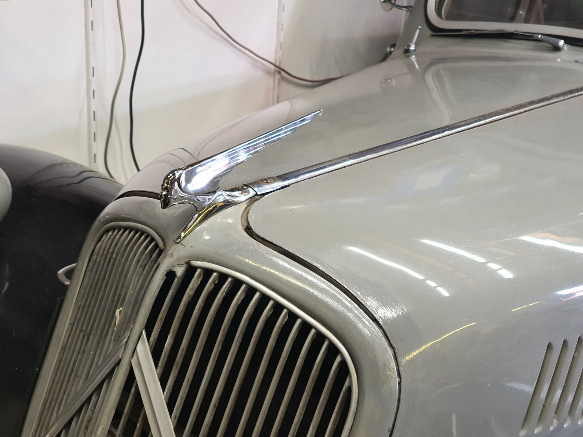
It took me over half a year to get the car in a nice external state, by repairing all bad parts, doing metal- and bodywork and spraypainting only  the repaired  parts. In this way, I preserved over 60% of the car with original paint.

I had to do a lot of bodywork on  the fenders, and some on the bottom of the doors, the raingutters of the roof, the outer parts of the bonnet, the edges of the rear window mount, the edges of the hood and the air inlet just under the front window.

UPGRADES

Later, I upgraded to the following parts (sequential order):

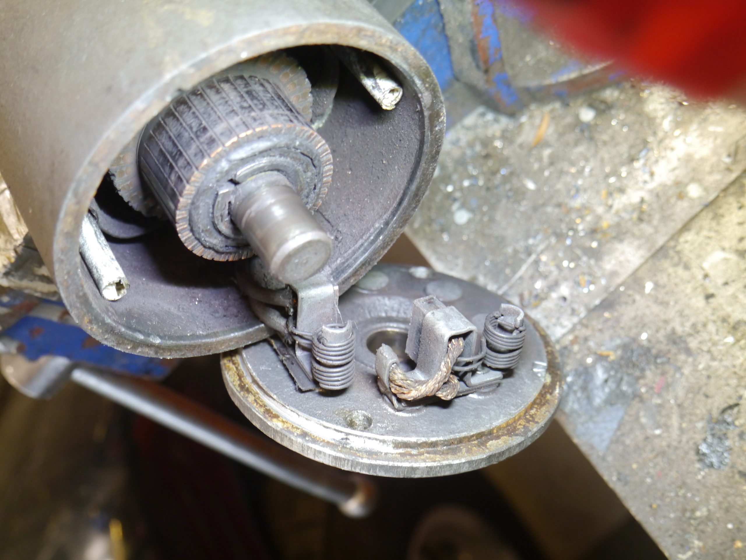
  • 12V AC dynamo, regulator and all 12V electrical components incl 12V starter

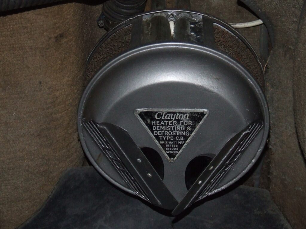
  • Cabin (coolant water driven) heater with front window heater

  • Electronically regulated cruise control with vacuum servo
  • Engine upgrade with a powerful  long stroke Citroën DW engine ***

really different than a standard TA11BN: carburettor LEFT
  • RPM increase of 15% on the waterpump/fan rotation speed (smaller V-wheel)

***: I mated the old 3-gear original gearbox to the old TA-motor that now has an ID19P underblock.  This is now my spare motor/gearbox set in storage:

MAINTENANCE PHASE based on max 2000km/year

Every year:

  • Top off the valve saver fluid.
  • Before the car is parked in storage, add fuel preserver fluid in the gastank and then run the engine for a couple of minutes.
  • When I pick up the car after storage, I always check the coolant level and the brake level fluid and I make sure all brakes work properly. If I need to top up the DOT3 brake fluid, check which wheel is leaking and check that wheel and brake pistons for any wear. Clean up and mount all properly back.  Check tyres for wear, correct fit and pressure. Check horn. Check wipers. Check lights. Check engine oil. Check fuel levels. Top off the valve saver fluid.

PLUS Every 2 years:

  • Fill all the grease joints with appropriate grease, according to the TA’s grease scheme. This goes for steering, suspension, old model drive axles, drive shafts & bearings, gear selector rods and -mounts, waterpump, and so on.
  • Replace the engine oil with non-synthetic 10W40 every 2 years, since this car does not have an oil filter.
  • Measure the hygroscopic value of the DOT3 brake fluid and exchange the fluid when needed.
  • Check the level of the gear box oil and top it off with non-synthetic 30W80 engine oil.
  • Adjust the engine’s valve clearances.

PLUS Every 4 years:

  • Check the spark plug gaps;
  • Check the head light’s height settings
  • Check the front wheel’s toe setting, and adjust when needed.
  • Check the brake clearances and adjust when needed. Also, I check the speed at which the brakes free themselves after using them and when this is slow, I take of the hub and make sure everything moves smoothly. I needed, I clean the brake pistons and caliper of all wheels (If 1 moves slowly, all need maintenance).

Afterthought: I am glad that I am by now very experienced in doing all of my maintenance myself, and having a place to work with all the required special tools available helps a lot!

For things to come: Please see THIS

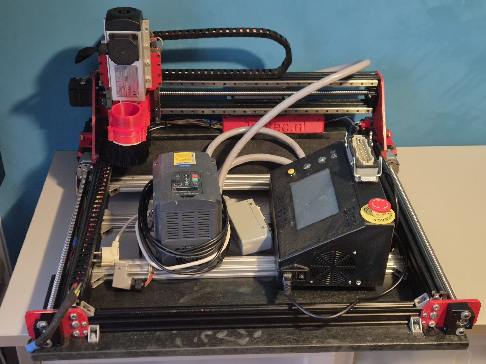
free STL downloads in 7 parts for CNC controller box with mounts for Duet3-6HC, PSU, AC-inlet, multiconnector, emergency shut-off, LCD panel, homing buttons and DC outlet

CNC_ctrlbox_V21_DUET3_6HC_LCDPANEL_C)JANTEC.NL_20251115

CNC_ctrlbox_V21_DUET3_6HC_TOP_PART_C)JANTEC.NL_20251115


CNC_ctrlbox_V21_DUET3_6HC_REAR_PART_C)JANTEC.NL_20251115


CNC_ctrlbox_V21_DUET3_6HC_FRONT_PART_C)JANTEC.NL_20251115


CNC_ctrlbox_V21_DUET3_6HC_BOTTOM_PART_C)JANTEC.NL_20251115


CNC_ctrlbox_V21_DUET3_6HC_RIGHT_PART_C)JANTEC.NL_20251115


CNC_ctrlbox_V21_DUET3_6HC_LEFT_PART_C)JANTEC.NL_20251115

ALL IN ONE BOX as 1 STL FILE:

CNC_ctrlbox_V21_DUET3_6HC_allinonebox_C)JANTEC.NL_20251115


CNC controller case free STL download Duet workbee Mellow FLY CDY with PSU, panic button, multiconnector and Fysetc Duepanel 7 inch

DOWNLOAD CNC_controller_box_6_parts_V2_C)JANTEC.NL_20251102

Please donate $1 to my paypal account if you use my original designs  -)

THE CNC CONTROL BOX

Download the CNC controller box design file via the above link in 1 piece which will take around a day or more to print.

The CNC box design is available in 6 separate design STL parts that interlock very well and  will have to be glued and (if you so desire-screwed) together.


The box is also available for DUET3 HERE

THE ENTIRE CNC CONTROLLER BOX AS 1 STL FILE:

THE ENTIRE CNC CDY CONTROLLER BOX AS 1 STL FILE: 

THE CDY BOTTOM PANEL:

THE ’empty’ BOTTOM PANEL: 

THE  LEFT PANEL:


THE  RIGHT PANEL:

THE  FRONT PANEL:

THE  REAR/TOP PANEL:

THE TILTED TOP PANEL:

REAR TOP PANEL PART CNC FLYCDY CONTROLBOX BY JANTEC.NL

The tilted top panel  houses a FysetC Duepanel 7 inch LCD module that interconnects to the FlyCDY2 or 3 ( and will also fit to the Duet3, obviously).

The box and panel also include holes for a 24-pins multiconnector on top, a panic button on top, an 80mm fan unit, a filtered power inlet unit (in my case, for 230V Europe standard) and 3 button holes on the tilted panel, as well as a small hole for a voltage reading unit.  Any other required holes can best be done after printing. Just with normal tools, by using painters tape first to cause minimal collateral damage to the case.

All parts that can be screwed on or-in, can utilize M3 threaded inserts at the mounting points inside. The holes are supporting these. This is not done for thePSU (obviously, the M4 mounting bolts run through the case). The fan is mounted with M3 bolts from the outside through the case and secured with nuts against the fan’s body.

CNC CONTROL BOX DESIGN, PRINTABLE IN 6 INTERLOCKING PARTS

HOW TO PRINT

I always print tools and toolcases in ABS at 260-270 degrees, 100% fan and 100% infill. .  Use minimal support of about 85% for these parts but always use maximal adhesion on the OUTSIDE only!

Also, set Cura to a shrinkage correction of 100.7%, due to ABS black shrinkage of 2.2 mm on the long side of the box. (The xSize should be 295 and this was measured 292.9 after being printed as full box)

For constructing the box from 4 individually printed parts, first connect the bottom parts without glue. Then, attach both the sides and screw in the front panel. Then, where needed file or sand off ledges so it all fits properly. Then, remount it all and let the glue find its way between the connecting overlapping ledges that connect the parts.

Print all parts with the vent openings down.

All parts will print best with support 85% AND adhesion outside only ON.

Print support with 85% angle support everywhere at 5%, so the M3threaded bus-supports will be printed well.

PRINT ORIENTATION EXAMPLE (Cura, VORON 2.4-600)          

Please be aware that the 6-part design is developed with printing in mind, so the horizontal printing orientation as shown above is the only way to avoid overhangs in the interlocking ledges.  This also goes for individual printing of each part.


I print this with an 0.8 mm nozzle at 0.4-0.6 mm layer height and a full print-run of all items at once still takes 1 1/2 day, at 100mms speed.

Therefore, I am now printing each part individually so I can manage it a lot better.  No fun when you run suddenly out of filament..-)

Please donate $1 to my paypal account if you use my original designs  -)

DOWNLOAD CNC_controller_box_6_parts_V2_C)JANTEC.NL_20251102

EXAMPLES WITH MOCKUP_PSU and CDYV3 board:

EXAMPLE OF A previous release PRINTED IN 1 PIECE:


STL download single- or dualcolor articulated egg cup

COLOR1
COLOR2

Please donate $1 to my paypal account if you use my original designs !

joined colors for my E3D toolchanger
Printed this very fast with 0.3 mm LH in PLA on my E3D toolchanger
Colors combined in 1 STL
     
Printed this on my original Prusa mini in black ASA with 0.2 mm LH

Mazda3 BK 2004 – Replacing Front Brakes: Calipers, Pads, Flexible Hoses and Rotors

About 2,500 km ago, we had the brake pads and rotors replaced on our 2004 Mazda 3.

But lately, there’s been an occasional squeaking noise coming from the front end, especially when going through roundabouts.

In my experience, this is usually caused by a stuck brake caliper.

As a result, the brake pad cannot retract sufficiently after braking, causing that pad (or both) to rub against the brake rotor. This can cause the rotor to squeak. It’s also possible that everything eventually gets so hot that the whole system catches fire.

Usually, simply loosening the caliper isn’t the solution because such a caliper isn’t stuck for no reason.

A repair kit usually isn’t a solution either, because it’s often the steel cylinder itself that’s rusted to the rim.

This is due to age, the Dutch climate, and insufficient maintenance of the brakes. The protective cover on the outside of the piston can become loose and let moisture in, or even tear over time.

Identifying in a timely manner that a part is no longer moving properly where it needs to—so that you can restore it to working order—is not part of an APK inspection but rather part of regular maintenance.

Unfortunately, many older cars suffer precisely from a lack of regular maintenance because there’s only money or time to fix problems rather than prevent them.

That was certainly the case for us as well.

Before replacing the brakes, we decided to take a preventive approach and replace everything that was likely due for replacement anyway—at least as far as the front brakes are concerned.

So: We replaced the brake calipers, brake lines, and brake pads. I had measured the brake rotors before ordering the new parts, and they’re still within factory specifications and appear to be completely flat.

On the left is the new brake caliper; on the right, the shiny new flexible hose. Just barely visible at the bottom is the left jack stand under the subframe. You can also clearly see the nearly new brake rotor. Also note the cap at the very end of the flexible hose’s swivel joint, which is there to prevent leaks as much as possible.

This morning, I first parked the old car outside and backed the Mazda into the garage.

I jacked up the front of the car and placed two jack stands under the subframe, lowered the car, and—as a precaution—placed the jack under the subframe, just clear of it.

I removed the wheels and performed an inspection. What stands out is that the left wheel is stuck, while the right one is completely loose. Upon closer inspection, it turns out that the left brake caliper must have gotten very hot, as evidenced by the blisters on the paint I applied years ago after a thorough refurbishment of the brake calipers and pistons. Those blisters aren’t present on the right side of the brake caliper.

When pushing the brake piston back, it worked on the right side but not at all on the left. Removing the brake caliper from the brake arm went very smoothly on the right, but on the left I had to use a press to push the brake shoe and piston back so that the brake caliper could be removed from the disc and the brake pads.


A quick note on the removal sequence:

  1. Jack up the vehicle under the subframe
  2. Remove the wheels
  3. Disconnect the flexible brake line from the caliper using a special 10 mm brake wrench and a 14 mm open-end wrench; then temporarily place the caliper bleed cap on the end of the brake hose swivel to prevent leaks.
  4. Remove the caps from the rubber centering bushings on the back of the brake caliper.
  5. Loosen and remove the hex socket bolts securing the brake caliper to the brake strut.
  6. Remove the brake caliper spring from the front of the brake caliper. This spring holds the front of the brake caliper tightly against the brake strut after reassembly and ensures proper alignment for correct operation.
    Remove the brake caliper along with the brake pads.
  7. Remove the brake master cylinder from the rear. It is secured with bolts and Loctite. I always use my jackhammer to avoid damaging the bolts. You can also do this with a wrench. These are bolts with a standard 17mm head.
  8. Disconnect the other end of the flexible brake line. Only remove the retaining sliders AFTER disconnecting the line, because otherwise everything will rotate along with the brake line and swivel at the bottom of the connection point when you disconnect it. Use the 10mm brake wrench for this as well. It almost never works with a standard 10mm open-end wrench, and if you use locking pliers, you’ll also damage the swivel on the inside, preventing it from moving smoothly along the brake line. Unfortunately, I had to learn this the hard way a long time ago… -)
  9. Remove the retaining plates in the middle of the flexible line and at the connection to the rigid steel brake line. If the original ones are still in place, you’re in luck: If the penetrating oil has had enough time to work, you can slide them off fairly easily. There’s a small hole in the center on the pull side that a thin screwdriver fits into. Using a self-gripping plier perpendicular to the screwdriver, just above the plate, you can pull it right out. Otherwise, move it back and forth slightly to the left and right while pulling on the plate, and it should come out that way too.
  10. Thoroughly clean the areas where the flexible line passes through and spray some engine oil or preservative oil on them. Do the same with the mounting sliding plates.
  11. Reassemble in reverse order. Note the following: The mounting points for the flexible hose are fixed so they cannot rotate. The top one has a small recess in the hole, and the middle one has a flat side on the back, where the fork leg is located. You can rotate the middle one around the hose to ensure everything fits.

Extra tip: Do not secure the top locking plate until AFTER you have screwed the swivel from the rigid line into the flexible line by hand. Then press it into the hole, insert the locking plate, and then you can tighten the swivel with the 10mm brake wrench! Otherwise, it’s nearly impossible to find the exact position for the thread to engage.

When it comes to brakes in general—and this applies here as well—prevent unnecessary future maintenance or repairs by applying a sufficient amount of silicone grease to all moving parts, specifically: on the brake calipers where the brake pads come into contact with the steel components, on the brake caliper piston, and in the rubber bushings that house the bolts securing the brake caliper to the caliper body.

And very important: Be sure to apply LOCTITE to the first few turns of the brake caliper bolts and then tighten them to the correct torque. For rough work on the car, I almost always use one torque setting: that for the wheel bolts. So that includes the brake caliper bolts as well. My large torque wrench is permanently set to that value. I use my smaller torque wrench for adjustable torque.

BLEEDING

There are several ways to bleed the system, and for a replacement like this, bleeding is absolutely necessary.

I always bleed the system using my vacuum pump.

It’s connected to a collection reservoir; one hose goes to the vacuum pump, and the other hose goes to the component being bled. Brake fluid sucked out of the system remains in the reservoir.

Using the bleed nipple on the brake calipers, you control how much fluid is bled, while you need to keep topping off the car’s reservoir slightly so the brake fluid can flush through properly.

First, I bled the brake caliper that’s mounted closest to the car’s brake fluid reservoir—that’s on the left. Then the right one, and back to the left. Done.

Right after that, I mounted the wheels, moved everything out of the way, raised the car with the jack, removed the jack stands, lowered the jack, and took it for a quick test drive.

I could tell that the pads still need to bed in a bit on the rotors, but the car brakes just fine.

The pedal feels firm right away, and pressing it a second time feels exactly the same. Still, I’m going to bleed the brakes again next week, and I’ll take care of the rear brakes at the same time to flush them out—that was already on the schedule anyway. Good luck!

A WARPED BRAKE DISC AFTER ALL

BUT—during the test drive, I immediately noticed that the brakes were vibrating a bit. Apparently, the front-left brake disc has shifted out of its radial center (or is simply a bit warped), likely due to the stuck old brake caliper.

So I ordered new discs from Hella right away; they’re usually better than those from an unknown brand, but we’ll see what we get.

Luckily, I still had a round of bleeding scheduled, so I went ahead and replaced the front brake discs at the same time.

EXTRA FOTO’S


oude en nieuwe remklauw
De oude spullen.

Download free vertical sun shade hood STL file for Tomtom Rider 410-550

I designed this in Openscad and it took 2 days (off and on) to get it perfect.  I started with a horizontal sun shade I designed earlier.

Please donate $1 to my paypal account if you use my original designs !

Tomtomrider550_sunshade_horizontal,_M_20251011V10


But I really needed a vertical one for usage on my motorbike.

So I changed the horizontal sun shade I had made earlier to a  vertical one, which was very easy once I had the horizontal one really perfect.  It took a couple of fitting trials before I had it good enough.

I printed this all on my hi-volume Voron600 with black ABS at 275 degrees, nozzle 0.8mm and layer height 0.4mm, 32 minutes to print the complete sun shade for my Tontom Rider 550. I always have the parts fan at 60% except 1st 3 layers and I print at 120mms, except 1st layer which is 20mms.  Travel speed is 200 mms , rather low for this print at 0.4mmLH.

I use a rather high setting for Z-hop height at layer changes because this particulat ABS filament at this temp can give a small blob at the end of print lines and I don’t want the nozzle to jam into this at layer changes.   Nor do I want to retract any more than 0.2mm since I don’t want any filament to get stuck in my so-called cold-end.

The sun shade fits snug around the Rider 550 but if you feel it is not tight enough, then print the sun shade at 99 % for the X and Y multiplier factors in your slicer.

And- yes, you should be able to print this STL file on any 3d printer with any filament and use your own preferred printer settings.

You will get much nicer prints when you use a 0.4 nozzle in your hotend and set it at 0.2mm layer height.  It will then take around 2 hours + to print.  Cheers!

Please donate $1 to my paypal account if you use my original designs !

UPDATED (nightly version)

Tomtomrider550_sunshade_vertical_L_20251011V10


Tomtomrider550_sunshade_vertical_XL_20251011V10

ABS best speed- , fan- and temperature 3dprint settings

STANDARD ABS start settings

Nozzle: 265 °C,   Bed: 110 °C

Object fan: 25% max from 5th layer,  below this: 0%

MY USAGE OF ABS

I use almost only ABS for my professional prints with an 0.6 or 0.8 nozzle.

That is because it is cheap, makes very sturdy prints and it can withstand pretty high temperatures.

I use ABS mainly for car’s interior parts, garden goodies and so on.

For any stuff that gets in cantact with food, kids and so on I use PETG.

For any other prints and all multicolor prints I use PLA.

Since I use dedicated printers per type of filament, I hardly ever have clogs or ruïned prints.

ABS- my story

Actually, there is not one standard for ABS settings. That’;s due to the fact that not all ABS on the market is really the same type.

However, I can give you some hints for different types of ABS 1.75 mm filament, after my extensive experience with those specific types of filament.

DO PRINT MY TESTPIECE PRIOR TO PRINTING ANY OBJECT and inspect the brim, and the sturdiness of the wall adhering, and the layer adhering.

Regular ABS: nozzle temp 270 deg C (15 deg too low), bed 120 deg C, object fan 30% (should be 0%) , 0.8 nozzle at 0.4 mm Layer Height, printing speed set to 120mm/s, BIG BRIM everywhere, brim also at LH 0.4mm, line width set at 0.8 exactly, sliced all in Cura

DOWNLOAD JANTEC.NL’s TESTPRINT_tilted_raster_20250902V1_STL

If the print comes apart if you try to break it at low force like in the above picture, the print temp is too low. Same for the wings of the testpiece as for layer adherence.

If you observe a bubbly surface, your ABS is wet.  It will probably not be able to save it.  You can try to dry it in an oven or in a food dehydrator at 80 degrees C, for at least 10 hours.  My experience is that this is a waste of time and energy.  Just throw it away in the plastics recycle bin.

GENERIC ABS PREREQUISITES

  1. For all ABS, you need a hotbed at at least 90 degrees C but 120 deg C is better;
  2. You will also need a hotbed plate with either a layer of smooth PEI on it, OR a hotbed plate with textured PEI, which I use especially for my 0.8 mm nozzle prints.;
  3. In general, never ever use a toolfan.  Unless you are using low-temperature ABS like EASY ABS with the rquired lower bed- and nozzle temperature settings;
  4. Always use a completely covering enclosure for your printer;
  5. Always do a bed mesh that really works prior to printing ABS and make sure this is done at operating temperatures of both bed and nozzle;
  6. Print with a really big brim everywhere, at least 10 lines wide, also for your support structure;
  7. Print the first layer with at least your regular print temp, NEVER any lower;
  8. NO object fan on first 4 layers!

SUNLU ABS (WHITE AND BLACK)

Sunlu has ABS filament that is shiny on the spool, and can be printed shiny at the right temperature.  This filament is not very prone to warping.

Nozzle: 265 deg C

Bed: 120 deg C

Object fan: 30% max=regular, no object fan on first 4 layers

EASY ABS (RED)

This ABS is also shiny, makes very sturdy prints and needs lower temp than general ABS. And- it requires a bit of object fan speed. The prints come out shiny. This type of ABS is not at all prone to warping, as far as I experienced.

Nozzle: 235 deg C

Bed: 90 deg C

Object fan: 60% max=regular, no object fan on first 4 layers

GENERIC ABS (RED, matte)

This is the most difficult to print matte red ABS(on the spool)  and requires very high printtemp, and can’t handle any percentage of object fan.  The prints come out matte when printed under 270 degrees and at 285 deg they are shiny.  This type of ABS is very much prone to warping.  This is likely a type of ABS without any additions to it.

Nozzle: 285 deg C

Bed: 120 deg C

Object fan: 0% max=regular, no object fan on first 4 layers

Is E3D tool changer Z-homing with Voron TAP possible?

HOW DOES IT WORK WITH THE E3D TOOLCHANGER?

The system whereby the E3D tool changer determines the Z value of the four tools is fixed in the preset system files. This means that you perform a Z homing paper test for each tool to determine the deviation of each tool relative to T0, which is the leftmost tool. You enter the result in the config file as the Z-value for each tool, whereby I usually use “0” for T0 and the general Z-probe value, which I determine as the difference between the manual probe on the carriage and the nozzle height of T0.

First, you need to determine the Z deviation of T0 relative to the Z value of the carriage that picks up the tools. This is done by homing the bare carriage with a Z probe switch under the carriage to Z value = 0 on the bed.

Then you do a tool pickup from T0 and measure the height of T0 as the Z value. You then enter that value as the probe value in your config file. I find all this rather cumbersome, especially because everything changes when you change a nozzle, for example.

Below video: E3D toolchanger homing the carriage and do the tool pickup

DESIRED SITUATION

Ideally, I would prefer to have each of the four tools, i.e. T0 to T3, home X, Y and Z every time a new object gets printed, and in this manner you can also just select any tool to do the bed mesh.

You then take those four Z values as the Z=0 value per tool, and you’re done. This works great with the Voron that I run with TAP Z-homing! It doesn’t matter what you do with your bed or your hot end, gantry, etc. It doesn’t matter because the nozzle is used as a mechanical Z-homing tip.


The tool pickup (the trolley) is very securely attached to the X-axis. The best solution would be to allow this entire unit to move vertically in order to enable the TAP function. That is still a challenge, partly because the A and B belts are attached to this trolley. This only seems possible with a new trolley to which the belts are attached and a separate tool changer pickup next to or in front of it. I then still need to create the TAP function between the two parts. And if the tool changer is placed in front, the X-axis must be moved back on the Y-axes. I’m not sure how that will fit….

After exploring all kinds of possibilities, this one remained: Keep the tool pickup in the same place and work with existing resources. Saw the mounting block on the X-axis slider into 3 parts and then mill 1 mm off the centre piece on both mounting sides. Adjust the side plates to which the belts are attached so that these plates can be reattached to the middle section of the slider block with new countersunk screws. The through bushings on the bottom no longer pass through the plate, and the plate must be milled away at the corners, just like on the top, to create approximately 5 mm of vertical play. Mount the two lower connection points of both side parts with two 1 mm spacer rings each so that the carriage can move up and down and the sides remain at the original distance from each other in order to maintain the stability of the moving construction. An additional mounting block for the vertical linear rail of the TAP slider is placed on the centre mounting block of the X-axis slider. Extension pieces are attached to the front and/or rear of the tool pickup, to which the TAP slider with the moving part is attached so that everything can move up and down by approx. 3-4 mm..

How the TAP function works on a Voron2.4 3D printer

ADDITIONAL: Self-searching tool changer

And while I’m at it: why not make a self-searching tool changer? Roughly set it up with the XYZ coordinates per tool, the last part electronically with a guide system between the pick-up trolley and the tool, and the final fitting with the existing mechanical fitting.

Instead of determining exactly where each tool should be picked up and put away by trial and error, you could use an electronic guidance system to aim precisely at the right tool when it needs to be changed. No more hassle with X-Y settings and homing axes. Because if anything changes as a result of mechanical stress in the frame or due to small deviations from the X and Y homing, picking up and putting away tools will regularly go wrong.

One possible way to do this could be a passage LED/LASER system, such as those used at shop entrances.

.


mini focussable laser module


mini laser receiver module


Or simply use infrared, which is invisible but also much less dangerous.


To do this, you use a targeting laser, such as in a levelling system, or an infrared laser with a receiver.

This is placed on top of the X-axis on the moving toolhead and is aimed at the tools, at a 90-degree angle to the X-axis.

You then activate the correct tool you want to move to or pick up as the receiver.

With an X-sweep movement, you can make contact with the receiving tool and then move in a straight line towards the tool until you reach the pick-up point, which is specified in absolute Y value in the configuration file. Sounds like a great development!

ADDITIONAL: Precise XYZ homing of the tools

And I would like to have a way to centre X, Y and Z of each tool nozzle in detail relative to the other tool nozzles, just like with my CNC machines:

3D Print Head Alignment Block

With such a head alignment block, you can accurately determine the position of all axes on a CNC machine. First, you need to determine the approximate position of this block, with an accuracy of approximately 1 mm on the X and Y axes.

The alignment block is electrically insulated and works by making contact between the tool tip and the block.

How does homing with an alignment block work?
You programme a centring macro in G-code.
First, you temporarily set the motor power to the lowest possible value to avoid damage if anything is in the way of the moves to be made.
Just as when I regularly do a home-all, with this new method you also set the bed and the relevant tool nozzle to operating mode (e.g. bed at 70 degrees and nozzle at 180 degrees).
Then you do a normal XY homing, which in my case works with limit switches (or optical switches) at the start of the X and Y axes.
A Z-homing action is also necessary unless you do not want to remove the Z-move block that occurs when you have not first homed Z.
Then move the Z-axis up sufficiently to avoid hitting the block.
Next, move to the absolute XY position of the block.
When you are above the block with your tool, home your Z.
Then home on Z+0.3 both -X and +X, and in the middle of -X and +X home -Y and +Y.
The result is the exact position of the centre on the flat Z plane of the alignment block.

Because you know exactly what the position is in relation to the bed centre and from X0, Y0 and Z0, you can translate this directly into the macro and enter the Z0, X0 and Y0 values as absolute values.

It should be possible to home the E3D tool changer tools in this way as well, with Z using the TAP function and X and Y using electrical detection as described above for the CNC milling machines. We will see if and how this will work as a supplement to TAP-Z homing with the current X and Y microswitch homing on the X and Y axes.


CONCLUSION -FOR NOW-

The credo still seems to be: If the E3D tool changer is working, it’s best to leave it alone. That doesn’t suit me at all, because I often move my printers around. And that doesn’t always go well.

So I’m going to look into these issues and, if possible, build something!

garden wall with 3d printed hanging flower pots download free STL files

In my small garden, a wall from my neighbour’s house extension has always felt a sort of in my way.  I thought a lot about making this wall a bit more visually attractive and I came up with this:

I created a setup with impregnated wooden garden planks, which I splitted lenghtwise with my small portable sawmill.  The wood carries around 20 small 3d-printed flower pots in all sort of colors and shapes.

In the flower pots, I  put in a variety of small plants plants of which most of them can withstand the Dutch winter time, so I don’t need to replace all plants next year.

Also, I put in an automated solar-powered watering system that utilises my rain water gathering supply bins.

I am very happy with the result!

Below in this post I have gathered my flower pot designs for this wall, if you click the images, the STL file will be automatically downloaded to your device.

Cheers! Jan, 08-2025


square_plant_hanger_b100xd100xh110_V12_REVd_20250702 square_plant_hanger_b220xd80xh80_V12_REVd_20250701 square_plant_hanger_b80xd80xh100_V12_REVc_20250701 Diagonal_plant_hanger_T110_B90_H125_V2_20250701 Square_diagonally_placed_plant_hanger_TOP110_BOTT90_HEIGHT225_V1_20250630

Facets_semi_round_plant_hanger_TOP260_BOTT170_HEIGHT220_V15_20250628c


Please donate 1 US Dollar to my paypal account if you use (parts of) my developed materials so I can continue to share nice stuff for you to download

FREE STL DOWNLOADS reducers, bends, offset pieces, mounting brackets and wall bushings for 55×110 mm air ducts

10mm wall plate for 55x110mm air duct. The wall plates are glued in place in the wall and are also used for  covering the sides of the through-hole in the wall. The 55×110 air duct will then pass through the glued-in wall plates on either side of the wall.

40mm wall plate for 55x110mm air duct.
wall_plate, extended to 60mm for 55x110mm air duct. This piece connects through the wall  and fits in one of the above wall plate-pieces
wall plate with short 90 degrees angled bend. Both sides connect to a 55x110mm air duct


90 degrees bend for 55x110mm air duct
90 degrees bend for 110x55mm air duct
pipe connector piece with 15mm offset, both sides connect to a 55x110mm air duct
slim mounting bracket for 55x110mm air ducts


transition piece from round 150mm air filter box output to 55x110mm air duct, wall_mounted
endcap for 55x110mm air duct


CREALITY FALCON2 PRO 22W laser versus LASERTREE LT-K60 laser

The Creality Falcon pro 22Watt Laser unit is the standard delivery for the ‘entry’version of the Creality Falcon 2 pro enclosed laser engraver/cutter.

The Lasertree LT-K60 laser is available as just the laser unit.

READ THESE ARTICLES FOR AN IN-DEPTH REVIEW OF THE LT-K60

There’s a lot of similarities between both lasers, and quite a lot of differences.

Obviously, the power outage differs.  I do not own a Creality 60+ watt laser, but from my research I know that the Creality Falcon2 60 Watt “+”  big blue laser is in size comparable with the Lasertree 60 Watt blue laser version.

Both Creality’s laser as Lasertree’s laser make use of 6 Watt blue laser diodes in arrays of 4 pieces per stack of 20-24 Watt.

The laser light come from the side of the housing and is defleted by mirrors so the light beams will all come at the same place through the beneith mounted lens.

If you need more power, one or more stacks of laser diodes are placed on top of the existing stack.  This is the reason that these type of lasers are more precise when you use less stacks of laser diodes. The switchable power of the big lasers like the 60 Watt types  can either use the lowest stack for 20/22 Watt, the lowest and middel Pack for 40 Watt or all Packs for 60 Watt.

Then, for the real difference between the Creality Falscon pro laser and the lasertree laser: The Lasertree is a so-called ‘plain’  laser. No intelligence, no smoke or flame detector, no air flow detector and so on. There is a temperature guard though which includes an alarm signal and front temperature readout. The only electrical connector is for power and PWM.  This has a 3-pin connector and that’s it.  If you use the Lasertree laser, it is recommended to do all your monitoring and safeguarding separate, either next to the laser or somewhere inside the enclosure.

The Creality Falcon2 pro laser holds on top of the laser diode stack(s) ,which by the way also include cooling body and fans, a PC board with a.o. a microprocessor.  On this board, all cabling is done to the external and internal users. And-also a USB-C connector is externally accessible for upgrading the firmware.  The laser unit is connected to a connector box, left on the X-rail.  the cable is connected to the connector box with a 10-pin (BTW, only 9 pins are used) standard 2.54 connector.  The cable enters the laser module on top and is safely mounted.

On the internet, I found quite a lot of users that opened the 22 Watt Creality Falcon2 laser due to errors after either bad type of smoke clogged the laser, or some pitfall happened due to inexperienced usage like overheating due to clogged cooling fans.  You can find these user stories HERE.

As I look at it, the Creality Falcon 2 ‘s laser unit is a very smart design, due to the upgradeable processor, smoke and flame detection, and air flow detection.  The status of these sensors is exchanged with the motherboard so  when things go bad with the unit or the job at hand, the machine will terminate any ongoing job to prevent damages to the machine and its surroundings.


And- as for the Lasertree 60 Watt unit? I was going to use it in my Indymill CNC setup, and I still feel that this is a smart move.  However, I did order a couple of additional sensors like flame, -smoke, and airflow detectors. I intend to make myself a small Arduino board or possibly an esp32C3 board to check on the ongoing laser jobs. I have plenty of space to mount this on the Indymill and connect it to my controller system. Will let you know how this progresses!

Data and pictures LTK60:

Case&Lid STL DOWNLOAD (zipped)

Laser cutter Creality Falcon 2 pro – installation

Finally I made the transition to a robust diode laser machine for my wood and acrylic cutting work. Until now, I have been using my K40 CO2 40 Watt laser cutter/engraver. I will continue to use the K40 machine for clear glass, as it cannot be cut/engraved with a diode laser.

The Creality Falcon 2 Pro with 22Watt output power is chosen because the laser is quite powerful, but mainly because I will be using this machine in my study with an exhaust vent through the roof of the house. I have the K40 CO2 laser in the garage, which works fine. But it is difficult to use easily because of the limited space in the garage. I wanted to keep my big laser ready to use, which means that I need a permanent setup. Because the K40 is water-cooled and has a fairly large cabinet due to the large laser tube, it doesn’t really make it easy to handle when moving it all the time.

The Creality Falcon 2 Pro has a relatively small cabinet and a closed housing. therefore, I could put it in my existing  in-house 3d printerroom.  It did not go easy, though. I needed to get a couple of 3d printers decommissioned to make the required space available.

For the exhaust of the Creality Facon 2 pro laser engraver/cutter, I have installed a filter cabinet with a coarse and fine filter + carbon filter.  This can get the exhaust gases somewhat filtered so they can be safely discharged. This is especially necessary with acrylic and other plastics.

The above connecting piece between the metal filterbox and the laser housing was designed in Openscad, and printed in white ABS on my Voron600.

The exhaust pipe runs from the workroom on the first floor to the second floor and then a short distance through the house to the former exhaust of the central heating boiler. I no longer use that central heating boiler because of the heat pump.  All special connecting pieces have been designed in Openscad, printed in white ABS on the Voron600.

The 110x55mm exhaust pipes are flat pipes so that I can run them neatly along the wall with standard available 90-degree bends in the corners.

There is a high-volume additional retraction fan mounted just before the outlet through the roof.


User review BYD Atto3 from October 2022 driven during 2.5 years and 50.000 kilometers

Writing this on May 9th 2025 after almost 50.00 kilometers, I trust that this user review of my Atto3 may be useful to others.

The car is now well over 2 1/2 years ‘old’ and has never had any defect, never got me stranded nor did I ever need any assistance to drive it.

In my earlier review I made some comments about the poorly functioning airco, no homologation for a pulling rod and so on.  You can read those comments here:

Climate control system fails in BYD ATTO-3, still getting fogged windows

BYD Atto 3: User experiences after 9 months and 10,000 miles

I did a couple of upgrades to the car, these can be found here:

BYD Atto3 upgraded black C-pillar covers

BYD Atto 3: Mounting an original BYD dashcam DIY

BYD Atto 3 tow bar

BYD Atto3 -Spare tire in the trunk

BYD Atto3 on all-weather tires Bridgestone 235/50 R18 101H XL (GAN) Weather Control A005

I have 1 pending upgrade, which is the automatic wiper control unit that I have laying around.  I am still a bit hesitated to install this, due to possible warrant voiding by BYD when I cut holes in the car under the steering wheel pillar’s plastic cover to mount an on/off switch for the to be installed wiper module.

The assessment about the car at May 2025:

The car drives perfect, BUT I needed a lot of getting used to the functioning of the airco/heater system, though.  The Atto3 works completely different than any airco/heating system I ever encountered in a car.  After 2 1/2 years I am finally getting the hang of using this system.  I have tried all options and found out that the ATTO3’s heating/airco when used in AUTO mode is dangerous to use in our Dutch weather conditions.  I get foggy windows, both in- and outside now and then, depending on weather conditions.  Like sudden snow, hail, or warm rain.  Fog is also a difficult situation to deal with when on AUTO setting.

Since I overcame that (-to me, at least-) disappointing fact, I fell back to manually controlling the airco/heater every time I start my ride and during driving.

So- when foggy and cold outside, I need both airco and set the temp to HI.  But this is not possible in this car.  I can either set the temp to LO which is airco cold air only OR set any other temp which is heat only.

When foggy and warm outside, I only use the airco and thus set the temp at LO.

When cold and NOT foggy, I set the temp at 24 degrees, turn temp back to 20 when heated up.  Keep changing temp between 19 and 24 to keep a sort of stable temp in the car.

When warm and not foggy, I set the temp to LO to put the airco (which is cold air only) ON.  When the temp reaches a convenient point, I set the airco OFF from LO and put the temp to 20 but I cannot keep the airco ON, because setting any temp other than LO ends the functioning of the cold humidifier air. If the foggy window gets back due to not retracting moisture from the car, because the airco is off, I switch back to LO again and so on.

All in all, this is drivable but not very pleasant, running a manual switchboard on the climate control that should be better programmed.  I don’t know if there are any other people that may make better use with the airco/heater of the Atto3. If so, please contact me at info@jantec.nl.

BTW: Due to the above, I can’t really make use of the android-auto software, since I can only control the airco and so on when trhe car is NOT in android-auto mode….THIS IS SOLVED june 20th, 2025: The new software update solved the airco control problem when using android auto!  Now, a lower part of the big control screen is customizable for a.o. controlling the airco and system.settings while android auto is in use. This is a perfect setup now, although I still need to manually switch a lot to keep the fog off the front window under specific wet conditions.


CNC workbee control cabinet free OBJ and STL downloads with space for DUET3 6HC, power supply, panic button, 24-pin multi-connector and Fysetc 7-inch Duepanel touch-LCD

Due to the DUET3 control board’s size, it does not fit into the previously developed CNC housing for a FLY_CDY board, so a lot of modifications had to be made.  This resulted in the preliminary (V13) OBJ design which can be downloaded HERE (20250604)

This post has the published  last version with tight fits for the DUET3 6HC motherboard, the 24V PSU and so on.

The dimensions of the newer DUET version are smaller than the peliminary DUET3 version. Now, the dimensions are made the same as the CNC controller box that I made earlier for the Mellow FLY CDY2 or -3 motherboard and DUET Workbee, DWC LCD controller from FysetC and so on.

By now, I also have a workable 7-part release for this DUET3 6HC CNC controller box.

To print this 7-part version, you will need a 3D printer that has a minimum 300 mm span width of it’s printbed.

I found it a lot easier to print the controller box in 7 separate parts than in one big  print-run for just the box of around 1 1/2 day which uses 940 grams of filament.

DUET3 6HC motherboard

The box and faceplate for DUET3 6HC is available as:

  1. The old preliminary (V13) OBJ design HERE (20250604)
  2. The LAST available STL is available below for the BOX in 1 piece

CNC_controller_box_simplified_1_part_V20_FINAL_MOTHER_DUET3_6HC_BOX_ONLY_C)JANTEC.NL_20251108

3. The last available STL for the FYSETC 7 inch DWC font panel is below:

CNC_controller_box_simplified_1_part_V20_FINAL_MOTHER_DUET3_6HC_FYSETC_FRONT_ONLY_C)JANTEC.NL_20251108

SHOWN WITH MOCKUP PARTS INSIDE:

Version V20 of the Duet3 6HC CNC controller box with mockups inside and FYSETC 7 inch LCD DWC mounted, 2025Nov08

Please donate $1 to my paypal account if you use my original designs  -)

The old preliminary larger version of box and front panel, which is also OK


Side view of the CNC workbee DUET3 enclosure, with the cutouts for the reset, microsdCard, USB and Ethernet connection visible below, left of centre. The canbus connection can be seen at the front of the enclosure, at the bottom.
Side view of the preliminary version of the CNC workbee DUET3 enclosure, with the cutouts for the reset, microsdCard, USB and Ethernet connection visible below, left of centre. The canbus connection can be seen at the front of the enclosure, at the bottom., This is the old version which has the same dimensions as the V20 version but has the old JANTEC.NL text on the LCD front panel


TOP view of the CNC workbee DUET3 housing, with the cutouts and attachment points for the threaded inserts visible at top left
TOP view of the old CNC workbee DUET3 housing, with the cutouts and attachment points for the threaded inserts visible at top left
The V20 new version with PSU and DUET3D-6HC mockups inside for position examples
This pictures shows in detail the tight fit of the new  BOX’s version where the DUET3 6HC board is shown against the inner box’s walls. This is required for utilizing the board’s external sockets through the BOX’s outer walls like ehternet, canbus, reset, SDcard
Slicer’s result with mockups inside, this shows the in/outlet ports, reset, usb access port, cdcard access


Review and teardown cheap small banggood windmill 6 blades 44 inch wing span


Some results of my research on this so-called 500 Watts 24Volt wind turbine:

The span width is 44 inch, 110 cm.

It is realistically not possible to generate more power than 80 Wattts at any given time,  given the 44 inch span width.  Unless you have turbo winds and position the wind mill at a height of more than 30 meters at a sea shore.

The wiring of the windmill is not made to withstand any amperage above 1.5 Amps.

The wire diameter of this 24V version is 0,8 mm, including coating.  That is 20 gauge. This is rated at max 1.5 Amps. Times 24Volts x 3 phases AC is theoretically max 130 Watts.   If the blades can catch maximum amount of wind, which is in practice limited to max 80 Watts due to world-given natural limitations.  To get more power from wind, the blades must exceed a length of 5 meters (15 feet) with a span width of 10 meters (30 feet) and you need a setup height of at least 30 meters (100 feet).

80 Watts is fine BTW if you use this wind mill in a small off-grid setup and position the wind mill at a height of at least 5 meters (15feet) above the tallest building around.  Which is exactly the local limit to get a permit where I live (in the Netherlands, EU).

The mechanical construction is OK, although I doubt that the slip rings will survive in the long term.

And- the main bearing is also the water seal, which I think will not work on the long run. A seal cannot be put on the shaft at the outside because the  blade holder is mounted directly on the shaft and is fitted against the inner part of the bearing.–)

My 3D printers LIVE action


Free STL download 2-part case for SEEED XIAO nano SAMD or RP2040

This is a tiny case for my XMAS LED projects, with RGB leds WS2811 or 2812B.

Please donate $1 to my paypal account if you use (parts of) my designs so I can continue to share nice stuff for you to download

download STL file small case Xiao nano&LDR&DS3231 with LDR hole 20241127 V14

Please donate $1 to my paypal account if you use (parts of) my designs so I can continue to share nice stuff for you to download

I also added a mini board with a clock chip, DS3231 to the XIAO USB-C board, and an LDR to make the RGB’s brighter when they are used during daylight conditions. An example Arduino code with clock function is HERE.

The LDR is mounted, the clock board is not yet mounted. A clock board is only required if you want to use the clock functions.  Using an LDR is highly recommended.

The LDR is mounted on the XIAO board’s top  on A0 and GND, so it can be flush to the outer skin of the case through the dedicated LDR hole.  Be aware to also add a 10K resistor between A0 and 3v3 since this board does not  have programmable PULL-UP resistors.

The mini DS3231 clock board is  connected to the XIAO’s pins A4 and A5, 3V3 and GND.  There is also a small battery on the little clock board., so the time will always be available.  I mounted the clock board so that the DS3231 chip is flat against the RP2040 chip. Then, the Data in and out of the clock board are then facing D4 and D5 of the RP2040. I used 2 Arduino pin headers to connect these data lines together. 3V3 aand GND are connected between the boards using thin wires.

Output to the LED’s is on pin 3 (D3). For the LEDS, also VCC and GND are required, either from the XIAO board’s VCC and GND pins or from the board’s 5V power supply +5V and GND connections.  The LDR is mounted making use of a little stud, cut off from the tiny clock board since they have to be removed from the clock board anyway.  This makes the LDR fit the box’s LDR hole perfectly.

For resetting an DR2040, a small hole is made to reach the little BOOT switch. This is sometimes required since the RP2040 can get bricked when a non-working void is uploaded.  Push the boot butten when powering up, release the button and the RP2040 is in recovery status. Up[load a simple program and the RP2040 will resume normal functioning. Then, the normal COM port will work again an normal flashing is again possible.

The case has a snap-on lid that will also fixate the outlet cable for the RGB LED’s.

Please donate $1 to my paypal account if you use (parts of) my designs so I can continue to share nice stuff for you to download

free download of a cable connectorbox for 3mm 3-wire RGB LED cable/connectors

Please donate $1 to my paypal account if you use (parts of) my designs so I can continue to do this

download STL file cableconnectorbox_30x14x14mmbox_3mmcable_V3_20241129


Free download STL files multicolor gadget open hollow multicolor 3d printer designs

multicolor_open_elliptic_sheres_inner_hull_main_Jantec.nl_V5_20240731.STL multicolor_open_elliptic_sheres_inner_hull_sub_Jantec.nl_V5_20240731.STL multicolor_open_elliptic_sheres_mid_hull_main_Jantec.nl_V5_20240731.STL multicolor_open_elliptic_sheres_mid_hull_sub_Jantec.nl_V5_20240731.STL multicolor_open_elliptic_sheres_outer_hull_main_Jantec.nl_V5_20240731.STL multicolor_open_elliptic_sheres_outer_hull_sub_Jantec.nl_V5_20240731.STL

CFFFP_multicolor_open_elliptic_sheres_mid_hull_sub_Jantec.nl_V5_20240731 .3MF

(file voor (E3D) toolchanger met 4 x PLA en direct drive extruders)

Please donate $1 to my paypal account for using any of my designs so I can continue to do this

Import all 6 STL files into a  slicer that is set for use with a 3d multicolor printer. Then, assign each ring to a specific color, merge and export the gcode file to printer or flie.

Example of the outer ring STL file:


Video van WhatsApp op 2024-08-16 om 09.53.26_e051923f

Jantec.nl/en : Our English site is no longer fully mirrored to our original Dutch website as of July 1st, 2024

New posts and articles will first be made available on our Dutch site https/jantec.nl as of July 1st, 2024.

We do try to translate as many posts as we can to English, but this is pretty time consuming, so some articles will likely be only available in Dutch.

BUT we do have a translator module running within the Dutch website.

You can jump to our Dutch site from the main menu, everywhere within the English site.

Our Dutch site has fairly good automatic translation to virtually all commonly used languages and this Dutch site ishould work automatically in the language that your browser uses.

Cheers, Jan Griffioen Amsterdam, Europe.

Several STL design lampshades for 3d printer large socket E27 LED bulb


STL Download lamp_hood_12facets_whole_mini_dots_E27_20240621V13_PRUSA_MINI

Please donate $1 to my paypal account if you use (parts of) my designs so I can continue to do this

DOWNLOAD STL lamp_hood_all_versions_SMALL_shape96_round_pattern8_E27_20240622V15b2_PRUSA_MINI

Please donate $1 to my paypal account if you use (parts of) my designs so I can continue to do this


STL DOWNLOAD lamp_hood_all_versions_SMALL_round_E27_20240622V15b2_PRUSA_MINI

Please donate $1 to my paypal account if you use (parts of) my designs so I can continue to do this

STL DOWNLOAD lamp_hood_all_versions_SMALL_square_E27_20240622V15b2_PRUSA_MINI

Please donate $1 to my paypal account if you use (parts of) my designs so I can continue to do this

DOWNLOAD STL lamp_hood_all_versions_SMALL_PILLAR_24facets_pattern8_E27_20240623V15b3_PRUSA_MINI

Please donate $1 to my paypal account if you use (parts of) my designs so I can continue to do this

STL Design lampshade large socket E27 for 3d printer

DOWNLOAD STL  lamp_hood_oval_oval_holes_E27_20240621V14d_VORON_300

Please donate $1 to my paypal account if you use (parts of) my designs so I can continue to do this

DOWNLOAD STL lamp_hood_oval_oval_holes_E27_20240621V14d_PRUSA_MINI

Please donate $1 to my paypal account if you use (parts of) my designs so I can continue to do this

125 mm airco hose adapter STL printable file for standard 42x375mm window vents

air exhaust VERY SHORT 121mm round for window klein achter beneden 375x42mm ventilation sleeve angled 20240607V15b DOWNLOAD STL

The 125mm hose adapter just fits to print at 101% expansion setting on my Voron 300x300x300
Printed with 8% infill supports at 60 degrees angle support settings

arco hose adapter 125mm for window klein 2nd_3rd floor 275x42mm sleeve screw_on 20240612V16cDOWNLOAD STL

Video van WhatsApp op 2024-06-14 om 08.36.55_1fb3b4bf

BYD Atto3 upgraded black C-pillar covers

My Atto3 originally had silver colored C-pillar covers.  I ordered a set of black covers that can be mounted on top of the existing ones.  The result is shown in the added pictures.  Mounting these covers is very easy because along the inside’s edges a strip of 2-sided tape is plcaed. . Just remove the cover tape a bit, plac ethe cover where it fits, and carefully tear the cover strip entirely off the inside.  Press on and you’re done!

For reference, the car as delivered:


Replaced my softail’s rear shocks

I often drag my HD Heritage softail on roundabouts when I am not paying attention just with my left and right sides across the street.

This can be solved by giving the bike a slightly higher position.

To do this, you can lengthen the front fork slightly at the front and you can also raise the rear slightly by shortening the shock absorbers slightly on my Heritage softail. This is because a softail’s shock absorbers are not PUSH but PULL versions, so shorter shock absorbers mean a higher seat. If you make the shock absorbers longer, you lower the bike.

At Midwest motors in Australia a while back, I ordered 2 new chrome shock absorbers that have a wide adjustment range.

I adjusted these shock absorbers to the shortest setting and then fitted them.

This raises my bike about 3 cm higher at the rear while riding.

All done!

Harley Davidson Heritage lifted front fork 2 inch overstock

First, the light housing/ shroud’s rear parts are removed, the brake line to the front caliper loosened and the headlight’s internal unit has been removed.

Then,  the top BIG screws can be removed from the front fork units.  For this, I used my large socket wrench kit:

Then, I loosened the 2 bolts that clamp the front fork units in the lower steering plate.  Then, I upped the bike a bit with my Harley center lift unit:

With a little effort and use of some lubricant in the area around the lower forkplate at the place where they are munted, the forks will slide down. I let them slip down around 2 inch under the top steering plate.

The, remove the large bolts and be aware that there is quite some pressure under these bolts, due to the fork springs.  I put a steel plate between the bolt’s top and the hole where they were previously bolted.  The bolts come off with a bang.  The, they are captured by the plate.  Ater both bolts are loose and held by the steel plates, you can slowly upp the motorlift so the springs can move freely. The bolts will fall down so be arare to either catch them of prevent damage to your front fender and gastank.

NB: My HD Heritage model holds 2 identical springs so the procedure is the same for each of the fork units. In other models, you can encounter different situations like 1 spring on 1 side and no spring on the other side. This is normal.


Now, the new extenders can be mounted. Put them between the spring and the plate with bolt from a pulley pull-off device, as shown in the picture:

Then, drive the pulley device’s bolt through the bottom and push the spring in the fork, at the end screwing the new overstock bolt in the fork.  It should then be like this:

Secure the bolts in the foeks on both sides, push the forks up OR lower the lift and wiggle a bit until the bolt’s topsides are in the upper steering plate’s holes.

Then, put the  endbolts with new rubber rings in and mount everything back, Don’t forget the front brake’s line!  I refilled with new brake fluid, Dot 5.

So- I was searching for new 2 inch overstock shrouds but could not get them anywhere nearby.  Eventually, I ordered a new set with 4 inch overstock.  If it is too long, I will machine them down to 2 inch overstock on the lathe.  But that will be another post.

This is how it looks in real life:

And with the full package installed:

And- 2 months later: with the new overstock shrouds mounted:

Before and after the 2 inch extension:

Replacing the heater mosfet B6066 of a Mellow Fly SB2040 pro plus Canbus 3d printer’s Voron Stealthburner toolhead PCB

Due to my careless behaviour I damaged the hotend’s heater Mosfet of my Voron 2.4’s Stealthburner toolhead’s PCB.

This toolhead PCB is a Mellow Fly SB2040 Pro plus. It has an accelerometer, a 2240 TMC, and it works with PT100 for the heater. It  works very well through Canbus and my installed PICAN USB-interface on the RPI.

But- when I was installing another nozzle in the hotend, I shorted the ceramic heater cartidge and blew the heater Mosfet. See the next picture:

I ordered a new toolhead board and now I could tell the part number:

I ended up ordering 5 pieces of replacement B6066 Mosfet modules on Ali, and they were delivered yesterday, within 2 weeks.

I desoldered the defective one with my SMD heatgun, and ut a new one in with that same heatgun, works very well!!

mysterious anonymous art placement in Amsterdam, Europe

https://www.washingtonpost.com/travel/2023/01/20/amsterdam-free-art-unknown-sculptor/

The mysterious art of Amsterdam’s ‘Unknown Sculptor’

The city of Amsterdam, Europe manages the works of an anonymous doctor. Here are 6 places to see it.

January 20, 2023 at 8:00 a.m. EST
In the heart of the Red Light District, tucked away between the cobblestones, lies the mysteriously placed bronze breastplate. (Noelle de Leeuw)
In the heart of Amsterdam’s Red Light District, in front of a magnificently imposing church, a piece of art in the road attracts just as many eyes as all the provocative scenery that surrounds it.

A bronze breast, gently caressed by an equally bronze hand, sticks out between cobblestones. The tiny sculpture raises just as many eyebrows today as it did when it appeared on a winter’s night in 1993, placed by an artist whose identity remains a mystery.

The anonymous artist was active throughout the ’80s and ’90s, operating in the dead of night and scattering a total of six sculptures throughout Amsterdam.

Rumors about the artist’s identity quickly spread, pointed fingers and all. The city council of Amsterdam, however, was able to reach the secret sculptor and struck a deal. The city was allowed to claim ownership of his work under one condition: It would keep the artist’s identity a secret.

The artworks are simply accredited to the “Unknown Sculptor.” And although Amsterdam has always been high on the lists of art connoisseurs worldwide, the story behind some of the city’s most accessible artworks remains widely unknown. Here’s where you can find the Unknown Sculptor’s work.

‘Man With Violin Case’

On Amsterdam’s West Side, the “Man With Violin Case” continues to rush for the tram. (Noelle de Leeuw for The Washington Post)

The first piece of work by the Unknown Sculptor appeared in 1982 in a location just outside of the realm of where a typical visitor would stray.

In “Man With Violin Case,” which has also been referred to as “Man Trying to Catch Line 10,” a headless man in a raincoat and hat is carrying a violin case and running as if trying to catch the tram, which stops right in front of him. After a few years, the man disappeared. When he returned, he had been painted blue. Quelle mystery.

Tweede Hugo de Grootstraat

‘The Little Woodcutter’

“The Little Woodcutter” is easy to overlook, sawing away on one of the tree’s branches. (Noelle de Leeuw for The Washington Post)

In 1989, a tree in the middle of the bustling city center suddenly had a visitor: “Het Boomzagertje,” or “The Little Woodcutter.” This little guy, who can be a little difficult to spot, is not far from Museumplein, which houses some of the most well-known and prestigious art in the world.

The woodcutter was placed in the night before then-Queen Beatrix’s birthday. Begging for any of this to make sense, Amsterdammers jumped to the conclusion that it was the queen herself who had been behind these artworks.

Leidsebosje park

‘The Violinist’

Next to the entrance of Amsterdam’s city hall, “The Violinist” has been playing since 1991. (Noelle de Leeuw for The Washington Post)

In the bend of the Amstel River is a round building that oozes grandeur: the Stopera. It houses both Amsterdam’s city hall and the National Opera & Ballet. Inside the former, next to the entrance, appears to be a bronze violinist breaking through the floor and striking his instrument as if he were delighting all those strolling along the water with a ditty.

The Violinist” is the only indoor piece by the Unknown Sculptor. The sculpture was initially intended to be placed in the sea, rising and disappearing from between the waves. It found its way to the city hall in 1991 and hasn’t left since.

‘The Breastplate’

Placed right in front of the Old Church, “The Breastplate” attracts eyes from each passerby. (Noelle de Leeuw for The Washington Post)

“The Breastplate” is still the most magnetic of the Unknown Sculptor’s works, attracting glances from most who pass by. It can be found in front of the Oude Kerk, which straightforwardly translates to the Old Church; consecrated in 1306, it is Amsterdam’s oldest building.

After the sculpture appeared in February 1993, the city quickly removed it. Within a week, it had appeared and disappeared again. Residents of the neighborhood made complaints about the bronze piece of art. It was a noise nuisance, with people stepping on it or hitting it with stones. It was inappropriate, next to the church. It was plain sexist.

The plate is seducing as ever, befitting its neighborhood. Except taking a closer look at this breast doesn’t cost you a penny.

Oudekerksplein

‘The Accordion Player’

“The Accordion Player,” a piece seen on the facade of a house in the Jordaan area. (Noelle de Leeuw for The Washington Post)

In Amsterdam’s Jordaan neighborhood, the anonymous artist struck again on an unassuming residential street. “The Accordion Player” (1994) is attached to the facade of a townhouse, in the style of what the Dutch call a “gable stone.”

Amsterdam is scattered with old gable stones, which originally served more of a practical purpose than the decorative one they do today. Street numbers were an unknown concept in Amsterdam until the 18th century. Before that, a gable stone would give a clue as to what kind of people lived in the house, or identify the business located there. Whether “The Accordion Player” is a nod to Amsterdam practices of yore or is merely an ornamental piece is unknown, but the musician is well worth a visit.

Anjeliersstraat 175

‘Three Dandies in Conversation’

Placed in 1995, “Three Dandies in Conversation” is the newest sculpture of the bunch. (Noelle de Leeuw for The Washington Post)

In Amsterdam’s Oud-West, you will find De Hallen, an old tram depot turned cultural hub that is full of impressive architecture and young entrepreneurs. The indoor food market Foodhallen is next to the movie theater Filmhallen.

Not too far from De Hallen, in the middle of bustling street market the Ten Katemarkt, there’s “Three Dandies in Conversation.” Three bronze sculptures of men with infants’ bodies sit on high steel chairs, right next to a stand selling top-notch Gouda and Edam. One of the figures features a top hat, and his chair is slightly elevated. What the gentlemen are deliberating is left to the imagination.

“Three Dandies in Conversation” appeared on the street in 1995, making it the last of the Unknown Sculptor’s Amsterdam artworks.

Corner of Ten Katestraat & Borgerstraat


Switched to a Chinese high-flow CHT nozzle – Now, what is wrong with this ABS printed test cube?

So- what do you think is wrong with this ABS printed testcube after my switch from a standard 0.5 mm nozzle to an 0.6mm Chinese CHT high-flow nozzle?

I did not change anything other than the Curaslicer settings from 0.5mm to 0.6mm and also in Klipper, in the printer.cfg I also changed the setting from 0.5 to 0.6mm nozzle diameter.

Obviously, I also resliced the gcode before printing the testcubes.

It has been printed on my Voron 2.4R1- 300. with a nozzle as shown in the below picture:

These specific nozzles should be able to produce more flow since the input channel consists out of 3- instead of 1- little hole.  The tip is – of course- only 1 hole.

Remedies:

After the failed print, I did the following:

Changed the ABS filament for a fresh pack. No change.

I checked the retraction settings in Curaslicer which were just fine, between 0.5 and 1mm.

Tested the gcode on my big Voron which also has an 0.6 nozzle and this worked just fine.

So- I checked the input of the filament for drag and it went very difficult.  Apparantly something causes drag in the way from the enclosed filament box to the extruder.

Exchanged the filament sensor because it caused quite some drag and this made some difference in the printed result but not that much.

Checked the extruder and recalibrated this, no change needed.  50 mm extrusion was indeed exactly 50mm filament going in.

All seemed OK but I still got the same blobby outside on the printed testcube.

So- finally I unscrewed the nozzle and- guess what: It is an 0.8 mm nozzle which came in the same small plastic bag along with all of my ordered 0.6 mm nozzles.  Should have checked this beforehand, obviously!

Put a new Chinese CHT 0.6 mm nozzle in from the bag and now ALL IS ALMOST WELL!  at least- a lot better.. AND the prints are pretty well usable,

Both pictures: Voron 2.4 printing ABS at 280 degrees, Cura and Klipper setting for an 0.6mm nozzle. Left has an 0.8mm nozzle mounted, on the right is an 0.6mm nozzle mounted, Both nozzles are the high-flow ‘CHT’ Chinese nozzle versions with 3 internal flow channels.I quickly printed a couple of red ABS parts that I need for my big Voron 2.4R2-600.

Small remaining problem: fuzzy X- and Y- walls

I am still working on the blobby surface, as is shown in the above picture, the right positioned testcube.  Will try with some other filament! It is not the fuzzy skin option, by the way.  It might be related to the high temperature that I use with this particular ABS filament, depending on the application I go up to 280 degrees.  Best to try this first with PLA on 180-190 degrees, I guess.

Just got a so-called bright idea- Could it just be that I always had the temp for my extuder way too high and that such a high temp  due to the better nozzle with more flow- is no longer required?

That might explain why the prints are now perfect and shiny- But the X an Y walls are somewhat blurry.

That might be due to the high setting for the extruder ‘s temperature.

I could also try to set the print fan on, or at least higher than my usual 25% for ABS.

Then I can see what the impact is, or just lower the extruder temp from 285 to 250 for my red ABS.  Give it a shot.  Will let you know!

BTW, I never ever had printed this ABS with a shiny XY surface.  It was always matte, also at 285 degrees. Possibly the standard nozzle just required a higher temparature setting?  I have actually never heard of something like this, we’ll see.

The following 2 pictures show what the printresult was when I printed at 240 degrees, 0.6mm nozzle and all of the rest was unchanged…

The walls printed pretty nice, only the top is not what I want.  I will dig into that later.

The sudden stringing when using the high-flow nozzle is obviously one clear indication that I am searching in the right direction for solving my fuzzy walls now.  Previously, I never had stringing with the red ABS filament.  The stringing was also a lot less when printing this ABS testcube at 240 degrees instead of 285 deg.

I will do a last test with the option to smooth the Z-surface better, will show this here as well!  Could also be that the wall width for the top surface is set wrong, we’ll see.  Or the temp for final printing too low, or the part-fan a bit too much at 30%?

Heated bed alternative fixture for Voron 2.4 3d printer

To mount my Voren 2.4 R2 600x600mm heated bed solidly on the 3 pieces of 2020 aluminium rails, I used an alternative way, instead of the ,ethod that is usually done.

The reason is that I am using TAP as Z-probe and I want the bed to be mounted as sturdy as possible.

To do this, I used M3 nuts in the rails under the heated bed, then a M6 washer and a copper M5 round threaded insert in which the M3 bolt can be mounted.

But- first I placed the heated bed on the 2020 rails and made small marks where the M3 nut needs to be placed EXACTLY!  Then, take the heated bed off and proceed.

The M5 threaded insert has a small cutaway ledge that just fits in the M6 washer, as is shown below:

This keeps the M5 copper threaded insert in place in the M6 washer.

Then, the M3 16mm long bolt threads in the nut that is placed in the 2020 aluminium rail.

After all these have been fitted, remove the M3 bolts, place the heated bed on the threaded inserts and put the M3 bolts loosely in, thread one by one a bit in, place all af the M3 bolts.

Position the heated bed square in the frame and tighten the M3 bolts.  You’re done!

This shows the fixture under the 4mm thick 24V 500 Watt heated bed. If the bed gets too much warped, I will buy a 600×600 mm 8mm aluminium plate for the bed and get a 230Volts silicon heater under it…
For reference, the original fixture with a reversed set-screw under the heated bed: also very sturdy!

Commisioning my VORON2.4 600 3d printer with OCTOPRINT, KLIPPER, CANBUS FLY SB2040 PROplus toolhead module + KNOMI V2, OCTOPUS Pro F429 motherboard and PICAN module

Before building my 600x600x500 (XYZ) Voron 2.4 3d printer, I decided which electronics I would use.

The choice for the electronics’ hard- and firmware was the following:

  1. Raspberry PI4B 2GB with Octoprint, Klipper
  2. Octopus pro 1.01 F429 1MB motherboard with KLIPPER firmware
  3. PICAN CANBUS adapter USB-CANBUS with Candlelight firmware
  4. Mellow/Fly SB2040 PROplus CANBUS module for the toolhead with CANboot and Klipper firmware
  5. BTT Knomi V2 in the Stealthburner toolhead
  6. 10-LEDS arrangement with 8 minileds for the Voron LOGO and 2 RGB LEDS for lighting the nozzle of the Stealthburner

Fitting the parts on the Stealthburner, it also has the TAP Z-sensor from ChaoticLab. When fitting, I did not yet have the KNOMI front on the Stealthburner.

The Controller software is made as follows:

  1. Raspberry PI, burned with RPI’s Debian Octoprint package through raspberry pi imager
  2. Raspberry PI, through the PUTTY interface:
    1. installed KLIPPER on the PI
      1. git clone https://github.com/Klipper3d/klipper
      2. ./klipper/scripts/install-octopi.sh
    2. installed Canboot on the PI
      1. Burned Canboot on the Mellow/Fly SB2040 Proplus via the USB connection PI-SB2040
        1. install CanBoot on SB2040
      2. Made an auto-startfile for the Canbus in the PI and reboot
      3. Burned Klipper on the Mellow/Fly SB2040 Proplus via the Canbus interface PICAN-SB2040
      4. Made the klipper.bin file for the Octopus board within Klipper on the PI and then burned it as firmware.bin on a FAT-32 formatted microSdcard.  Then, put the microSD card in the OCTOPUS board to load the KLIPPER firmware
    3. installed a couple of supporting packages on the PI
      1. klipper-led_effect, used for the RGB LEDS on the Stealtburner
        1. cd ~
          git clone https://github.com/julianschill/klipper-led_effect.git
          cd klipper-led_effect
          ./install-led_effect.sh
      2. Moonraker, used for the BTT KNOMI
  3. Updated all installed packages on the PI with sudo apt update and sudo apt upgrade commands, and git_pull commands,
  4. Uploaded the required config files to the respective shared  Klipper//Moonraker config directory
    1. printer.cfg
    2. knomi.cfg
    3. stealthburner_leds.cfg
  5. Reboot and check octoprint in the webpage.

NB: Instead of octoprint, you can also use Fluidd or Mainsail

Pocket watch ‘Cylindre 10 rubis’

Pocket watch ‘Cylindre 10 rubis’


I bought this watch on eBay, state to be a pre-WW2 pocket watch.

It does not run and the main spring appears broken.

But- it is in a repairable state and everything moves easily.

Most importantly- it has not been tampered with.

In my search for similar watches i could not find any with identical  inner mechanics, all watches that appear to be alike have different gears and so on.

I will update the repair later.

Building a BIG Voron 2.4 R2 CANBUS 600mm 3d printer

The firmware and configs of this build is described HERE

For a specific printjob, I really need a large 3d printer.

The largest printsize I had before building this big Voron 2.4R2 printer is my 330x330x400mm  A30M.

But that only does PLA since it does not have an enclosure and the bed is not capable of anything over 70 deg C.

After a lot of searching I decided to build a new Voron 2.4 3d printer, sized 600 x 600 x 480 mm.  the main reason for this build is that I really like to build someting instead of buying something that I will want to change afterwards anyway.

The external size of the printer for this build is 760x760x750 which just fits my available space.

Since the door-opening (width) of my printing shop is only 700 mm, I can’t build the Voron 2.4 any larger than this, at least not at one of the sides. I do want the printer to be able to get out of the room when needed. I chose to keep the height of the externals within 700 mm. This means that the maximum Z-printing height will be ‘only’ 480 mm.  If the printer ever needs to go outside, the top hat will be removed and it needs to be tilted 90 degrees before getting it out.  But that’s fine, I don’t think the printer will be leaving very soon.

The build is continuing pretty fast. All electronics and printed parts are available.  The 2020 extrusions were delivered yesterday, so next week I will cut, drill and thread the extrusions and will start building the frame.

Octopus pro F429 (more memory for using with Klipper)
Mellow Fly SB2040 V2 PROplus to put in the Stealthburner with all you need in one small package: TMC2240 driver. hotend MOSFET driver and temp reader, fan drivers, PT100 converter, RP2040 processor, multiple connections for endstops, RGB driver for LEDs, and on top of all there is also an internal accellerometer connected to the RP2040’s SPI pins!
The PICAN USB to CANBUS interface I use. It already has Candlelight firmware installed when bought from LAB4450.com

I evaluated to make a different decision for the build, though, on the Z-height versus the width OR depth of the build. I need only one side to be within 700mm and this might be the depth of the build. If I would choose to do this, the printable volume would then be 600mm width x 540mm depth x 600mm height.  That seems a lot better than 600x600x480.  BUT- In my experience of printing BIG parts, I never reached the top of my large printers, only ever needed the X and Y to be as large as possible. Make any sense?  In the end, I therefore stuck to the lesser Z-height since this will also fit well in my printer shop, because the shelves  difference in height makes the printer fit well, also if I want a top hat like in the picture below, on my old Voron 300.

My Voron 300 with the top head mounted. This gives the required clearing when printing higher objects.


The stealthburner extruder including hotend, although not yet installed, and the SB2040pro CANBUS module. The KNOMI module is also installed later.

As shown in the above pictures, I also installed chaotic lab’s CNC-machined TAP module with the OMRON sensor.  Since I will be using a bed with an X-Y of 600×600 mm, I expect that I will need a very good Z-sensor like hopefully the TAP will prove to be.

Alternatively, for a faster and more secure bed mesh I might want to put the IDM sensor in, at a later stage:


I first printed the extruder parts and all of the movement parts. I already had some leftover parts for the Z-axes from an earlier build.  For the gantry, I bought a complete kit of CNC machined aluminum parts.

aluminum CNC parts for the gantry
aluminum back plate for the Clockwork extruder, the top part of the stealthburner extruder.


For the time being, I will make the outside covers from thin triplex wood.  Only after all is well and I know the printer works perfect, i will decide how to move on.  My earlier model Voron 2-300 has all transparant acrylic covers and that is nice but always dirty from fumes.  I might go with aluminum dibond on all sides but the front. If I will use dibond, I will screw it directly on the 2020 profiles to get as much rigidity as possible.

I ordered and received a Tronxy 24 Volts 500 Watts 600×600 heated bed as is used in Tronxy’s large volume HEVO printer.  Thanx guys!

In this build, I will use 3 extrusion 2020 parts to mount this large bed in the Voron’s frame.  I intend to fit the bed including extrusions tiltable, hinged at the rear. In my view, there is no way I will ever reverse the printer once it is in place in my printer shop.  To reach the electronics, making a tilting bed is really the only solution.

Totally working, including the Mellow Fly SB2040 PRO with TMC2240 (with SPI and with DIAG1 on pin sb2040:gpio8!!!).
I never want to turn the printer over, besides, that is not possible at all in the available space. That’s why I placed the din-rails with brackets between 2 pieces 2020 and all hardware accessible from above, ,with hinged hotbed.
The hinged bed with Tronxy’s 24 V 500 Watt hotbed attached…
Cables made to length, new connectors attached and everything made neat.
I forgot to switch off the power from my Voron 600 printer, when changing the nozzle. I accidentally shortcircuited the heater in the hotend and the result is shown in the above picture. The heater’s mosFET is toast. I have ordered a new SB2040V2proplus, and when it arrives I will see which type of MosFet I need to order for the repair…

The above concludes the build of the hardware.

The repair of the Hotend Canbus module, the build of the enclosure and so on will all be added as additional posts.

The firmware and configs is described in another post HERE

Video van WhatsApp op 2024-03-16 om 14.34.15_29d2041d Video van WhatsApp op 2024-03-16 om 14.33.45_8bd30d74

Chevrolet Camaro 1970 3D armrest reproduction

If you are interested in purchasing these original jantec.nl designs, please email us at info@jantec.nl!

My brother owns a completely overhauled Chevrolet Camaro with power windows (I believe from 1969 or 1971) and asked if I could scan, improve and reproduce the armrests since these are both quite sloppy.

This type of Chevrolet Camaro is the only version that has these large armrests and they are a typical product from those days.

Manufactured from plastic and covered with some kind of latex.

Due to time and usage these armrests are both L and R broken between the actual armrest and the handle that is used to close the door.

This handle is at the front of the door and with these long and heavy doors some force is required to close the doors.

Therefore, we will try to modify the armrest with an additional handgrip in the large part of the armrest.

So- I used my Creality lizard scanner to scan one of the the original armrests and cut the design in 2 connectable parts.  This makes it printable om my Voron300.

After 3d printing in ASA black, the parts got new leather upholstering.

After the right hand side was made to fit perfectly, we mirrored the design to produce the other armrest and handle for the left hand side as well.

The final result of the two 3dprinted parts joined on the right hand door

And the part for the LEFT door of the car
For proper scanning, I had to fixate the front of the armrest.

Scanning did produce a nice textured 3d mesh of the armrest BUT the scan proved to be inadequate when we mesured the length of the scan. This was 8.5 cm (more than 3 inch) shorter than the original armrest.

Above shows an impression of the scan that I made with the Creality lizard 3d scanner. After many retries this was the best I could get. It took a lot of rework to get it to a 100% match with the original armrest.  The armrest is actually too large to be scanned with the Lizard’s rotating platform so it had to be done manually.
In the above picture the diverted length is clear, left is the print of the scan (after rework to get rid of all debri).

Also, the mounting holes were only visible as small round indents in the hull and due to the length decrease they were not at the correct position.

And-another problem occured due to the broken plastic inside the connection between the armrest and the handle: It was very difficult to scan the original armrest with the plate attached.  The plate was however very needed because the handle needs to be fixated to get it at the right position for proper results with scanning.

Plus, the mounting spot that is at the end of the handle was severily damaged and the scan obviously also reproduced this ugly spot.  I reworked this with meshmixer.

Fixing the above and making the 3 mounting holes into the design with a Cad/Cam program (I used both meshmixer and Openscad to get everything done) proved to be very time-consuming.

All in all- I always do my time-keeping when I do specific work- it took around 72 hours of my PC time to get this all done, up until the workable version of the STL files that were OK to be printed.

For scanning I use my Creality lizard scanner on my gaming laptop with built-in RT3060 GPU.

For editing, I use my newest ACER XPS13 laptop with thunderbolt, connected to my Razor external thunderbolt RT3060 graphics box and an external hi-res monitor.

3D printing is the next step that is very time consuming, but thankfully I only need to start the prints up and afterwards get the prints off the machines.

I made about 6 versions of both the designs and the printed parts before everything was OK.

The handle prints in around 6 hours on my twotrees sapphire pro at 100mm/s, 0.3 mm layer height with hi-temp ASA filament (0,6mm nozzle and BIQU high temp direct drive hotend installed).

The large armrest 387 mm long part prints in 20 hours at 0.3 mm layer height, ASA high-temp filament on my Voron 2.4 with a 0.5 mm nozzle.

The results are shown below:

First compare of the 3d printed parts against the original.
This is only the door handle, i.e. the front part that gets screwed onto the larger armrest part with 4 pieces 8mm screws

Above, the repaired mounting hole and its surroundings is shown. This was done with meshmixer.

This design shows the added pocket that I made in the design of the armrest to close the door by using this grip without the need to use the front handle
Final version of the STL file that can be printed either as 1 part with a really large 3d printer or, as I did: print it in 2 parts and connect the parts with 4 pieces 8mm plugs


BYD Atto 3: User experiences after 9 months and 10,000 miles

This review replaces my previous reviews of my Atto 3, as all of my desired software enhancements have been completed filled in by BYD.

Meanwhile, software version 1.4 was loaded into the car via OTA on 18-9-2023 and as far as I am concerned, the car is completely OK in terms of software.

This is of course very personal. by now I am used to the beeps and other sounds the system makes when something is signaled or detected that I do not always immediately interpret as dangerous.

I have even learned to appreciate the fact that the system intervenes in dangerous situations. The other day I was driving behind a driver who suddenly hit the brakes in the middle of the intersection for some unknown reason. Before I could brake, the car was slowed down so that no collision occurred. I had not had similar intervention from the car before and was very pleased with it. It also shows that you really only know what you need when you have (unnoticed). So at this point I’m all over the place. Safety sometimes seems patronizing but avoiding a collision is enough reason, as far as I am concerned, to learn to appreciate the safety aspects of the Atto 3.

Intervention by the car on the steering wheel when you approach the edge of the road too much I previously found very annoying, and so did the accompanying beep. But I can also keep a little more distance from the shoulder and avoid the intervention. Matter of doing.

As I had mentioned in my earlier reviews, there were quite a few things that were just not set up nicely, which made driving the car uncomfortable. These were things like faltering A/C controls, or just the wrong air freshening functions available but also things like the fact that the A/C did not remember what the last setting was and should start with that again by default next time. That’s all fixed now, though.

Also promised afterthoughts like Apple Carplay and Android auto have been around for a while. I myself use Android auto and that works absolutely great!

Issues that remained:

1) I have the tow bar, but the car is officially not allowed to tow any weight because the car is not “homologated”. That is, there is no towing weight on the car’s Certificate Of Conformity. You can never get that later, only when the car is registered. Very unfortunate, especially since we were more or less verbally promised at the time of purchase that all that would still come.

2) No standard dashcam function while the cable is just pre-mounted. The camera is not mounted off-factory (for NL). I fixed this recently

3) No rain sensor for the windshield wiper. I was not used to that at all so it was getting used to having to operate the switches myself all the time. I can fix this and ordered the parts but I haven’t started yet. Read the progress HERE .

Other topics:

I retrofitted a spare tire myself, of course you never need it but when you do… yes, exactly!

And immediately upon geting the car I had the standard summer tires replaced with all-weathers.

Driving experiences

I have liked the car from my first drive in November 2022 in terms of driving experience and handling. The software improvements have made my experience even better. The Atto 3 does not drive like a small mid-size car but behaves on the road very similar to my previous car(s), Volvo V70. Maybe an odd comparison, but I also drive other cars with regularity and with that I experience difference but between the Atto 3 and a latest version V70 so not. You could also say that a V70 is a dodgy car, but that is not my experience with the last made version V70’s. PS: My last version V70 F (BW), 2 liter gasoline/LPG had an empty weight of ‘only’ 1450 kilos, the Atto weighs empty 1825 kilos….

Anyway, I was and still am very satisfied with the Atto 3.

As far as driving experiences and the range of the car are concerned, I have also experienced a few things over the past 15,000 kilometers.

Driving an EV is very different from driving a fossil fuel car. Filling up the charge level takes longer than filling up at the gaspump.

The Atto 3 weighs 1,825 kilos. Minus point associated with a relatively heavy EV: You really have to be very careful with some speed bumps, not to always just go over them at the advised speed. Often it goes well but I now have 1 in my route where I don’t want to go faster than 40 while there is an advisory of 60. On an 80 km/h meg. driving on it is OK, but when driving off at 60km/h it’s like falling off a platform.

Consumption and charging

But, especially on the trips abroad this past year, it turned out that everything goes very well when you check in advance WHERE you can charge WHAT with which pass or app. Because the Atto3 can ‘only’ fast charge at 88 kiloWatts it does take a while to charge the car all over again. So I do that at 40-50% remaining charge. And then 15 minutes is enough to be back at 90-95%. Then you may have to stop more along the way but I don’t mind that for 15 minutes. You drive with the Atto 3 from 100% to 50% about 210 kilometers. So stopping at about 200 km after 2 hours of driving so suits me very well.

And then you come to the real difference between fossil driving or electric: Everything you do costs electricity, and with an EV, so does range. Headwind: 10% less range. Average consumption at 90 km per hour is about 14 kW for 100 km, so a full tank of 60 kWh will get you over 400 km, even 420 km WLTP. At least, in summer at 90-95 km/h on a flat road without storm, without headwind and without too much load.

I have tried a number of driving scenarios and my most notable one is on the A2 from Breukelen to Abcoude at 130 km/h with no headwind or storm, though at night with lights on. Average consumption: 35 kW for 100 km. So if you would drive 130 km/h for a longer period of time, you would get barely 250 kilometers and then the battery would be empty.

Suddenly I understood why the Atto 3, but now most new EVs are capped at 160 km/h….

If you drive mostly on county roads and/or urban and you can control your foot a bit with acceleration, you can easily stay under 15 kW/100km, I sometimes even manage to average 14 kW/100km.

Of course, it still remains a small/medium SUV and the streamline also affects consumption….

BYD Atto 3: Mounting an original BYD dashcam DIY

I have driven my BYD Atto 3 from its purchase in November 2022 with a Garmin mini dashcam mounted in it, on the windshield just above right next to the interior mirror. That works fine, except you have a cable running that you have to get rid of and you have to use your phone app to view the footage.

According to the BYD dealer, it is not possible to retrofit the original BYD dashcam.

I removed the protective cover where the dashcam should go in, using appropriate tools for this purpose so as not to damage the plastic snap brackets.

It then turned out that the cable for the dashcam is just neatly mounted there. On the right side of the picture below, you can just see the mounting foot of the Garmin mini dashcam. The blue loose connector with yellow area is the connector for the original BYD dashcam.  Obviously, this is for a left-steered version but for a right-steered version the situation is just mirrored.

On Aliexpress I just came across the original BYD dashcam as a separate replacement unit, for about 83 Euro. So ordered it 2 weeks back and mounted it this morning.

Mounting is very simple: First remove the rubber where the lens of the dashcam should come through .

Then click the cable into the camera, it is automatically secured. Look very carefully how to insert this plug! It is a combined plug with 2 contacts for the power supply and a coax video connector attached to each other so it only fits one way!

And click the camera in the right place in the holder.

And…guess what? It just works. I also simultaneously had the update of the car to V 1.4 underway, and after booting up, the car detected that a dashcam was present. And the app was activated right away, so the camera now functions integrated into the car!

I then mounted the protective cover and neatly removed the Garmin dashcam mounting sticker and cleaned the windshield. When reinstalling the protective cover, I placed the large part first. Then turned the mirror down under and inserted the small part into the large part. That took some very careful work…

.

The software is self-explanatory: you do need to insert a MicroSD card under the dash. I have a 128Gb MicroSD card in there and I formatted it to FAT32 via the car software’s camera app.

What you find after using the camera is a number of directories on the microSDcard. your files are in the DCIM folder, arranged by video and photo.

The app allows you to change a number of settings including the recording time per recorded clip. I always set that to the longest possible time, here it is 5 minutes. just like the Garmin.

You can watch live and then also take pictures. I have programmed a quick button on the steering wheel to allow the dashcam to take recordings when I feel it is important. Of course, the app always makes recordings anyway, which are kept for a short time because of the size of the storage on the MicroSDCard. when the card is full, the oldest recordings go off. But when you initiate a recording yourself then this recording is always saved on the MicroSDCard.

Programming the camera power button for protected (non-erasable) recordings) goes like this: You use the screen rotation button on the steering wheel for this purpose. Press this button for 5 seconds until the large LCD screen gives you the choice of what you want to connect to this button. So I chose video recording for this.

If you want to copy recordings, the easiest way is to copy them to a USB drive via the file manager app of the BYD software. just copy from MicroSDCard/DCIM/…. to USB/… paste like on your phone.

That’s it! Have fun with your dashcam in the BYD Atto 3.


Traction Avant 11BN art deco hood mascotte install

Now and then I check my preferred suppliers for the availability of a so-called ornement de capot, in French.

This is a hood mascotte, originally fabricated by ROBI for a.o. Traction Avant 11BN and BL.

To my surprise, Franssen in Belgium had a new stock of these for my BN and I ordered me  one, it got delivered very fast and today I installed it.

It does only fit in 1 existing hole, so I needed to drill the front hole new.

The radiator grill needs to be removed to do this.

Behold: The Traction Avant 11BN with a Citroën ID19 4-speed gearbox!

I am very pleased with it!

It feel it matches my Traction with its repaired paint and original patina overall looks very well.