Looking at all the different IDEX designs that are based on either a coreXY setup, a Prusa3, Bear or not-, or on an Ender3/10 setup, I chose to do it from scratch.
An IDEX printer has independantly extruders, but nowhere is mentioned in what sense or -way the indepentand extruders are defined.
Since I have much experience with my dual Bear setup, where I park the hotend carriages and use 1 moving centerpiece with electromagnets to catch either the left carriage with hotend or the right carriage and hotend, I think that making a new printer for IDEX from scratch will be a good idea.
I did get my I3bear with IDEX on a single X-axis with magnetic carriages on the same axis running very well in the end.
Contrary to my A30M with a Chimera fixes dual hotend/extruder. That works very well, but also has its limitations. Limitations like low speed and the fact that you will always have some dripping on your object from the other nozzle, that is fixed at about 22mm to the right or left of the active nozzle. But- it is a really good solution for an 0.6mm nozzle, if you push the layer height to 0. 3 mm.
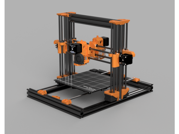
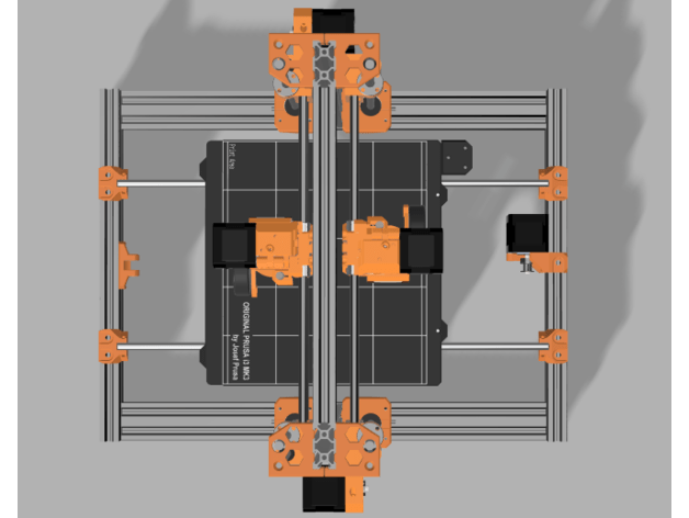
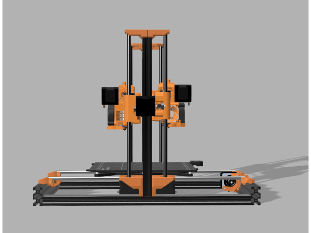
For my IDEX setup I will to use a standard Bear frame, made from 2040 aluminium, and all axes are based on standard I3 dual rods. Then, add a frond and a rear X-axis to the frame with each having its own Z-drives. Then, it looks like this:
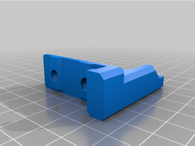
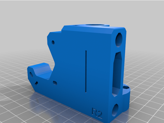
The only additional printed parts needed are the X-axis motor holder for the rear and 2 top Z-holders:
The rest is all standard I3bear stuff.
For this printer I need a motherboard with 7 drivers, being 2*X, 1*Y, 2*Z and 2*E.
Since I have a Fly407 MB with 9! driver positions in stock, already programmed for RRF3, wifi and with an LCD unit attached, I will use this to get a Duet setup with Duet Web Controller along. easy to reprogram, and I can finally check the board’s capabilities.
I just need to get me a casing for the board, but that’ll not prevent me from using it!
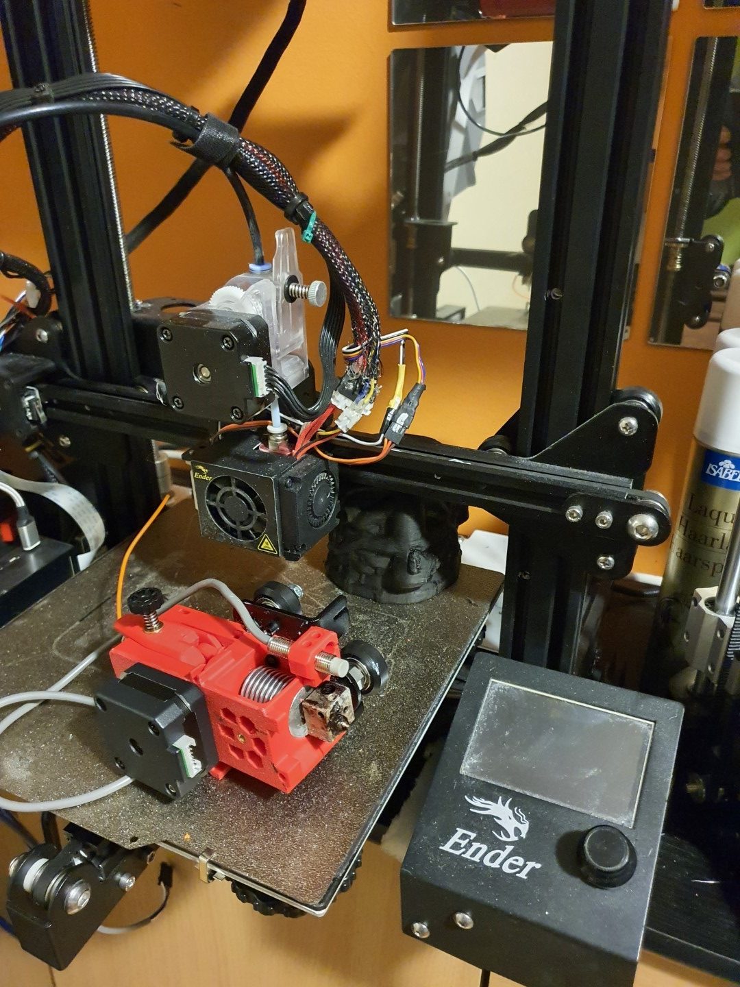
In 2020 I upgraded my Ender 3 with synchronised Z-axes and a new motherboard, the SKR Mini E3 V2.1.
The Ender 3 is very reliable and has been equipped with a direct drive bondtech extruder but still has the original hotend.
I chose the Ender3 to be the 3d printer on which I will attach the MMU2S. This also means that I will have to exchange the hotend/extruder combination with a Prusa Mk3S version.
Started this on May 4th, 2021. Only the printed parts were needed, all other parts were already available through sourcing form a.o. Ali. I printed everything in ABS, mostly red. For this I used 2 machines: The Twotrees Sapphire pro with enclosure for black ABS and the Voron 2.3 (300) for red ABS.
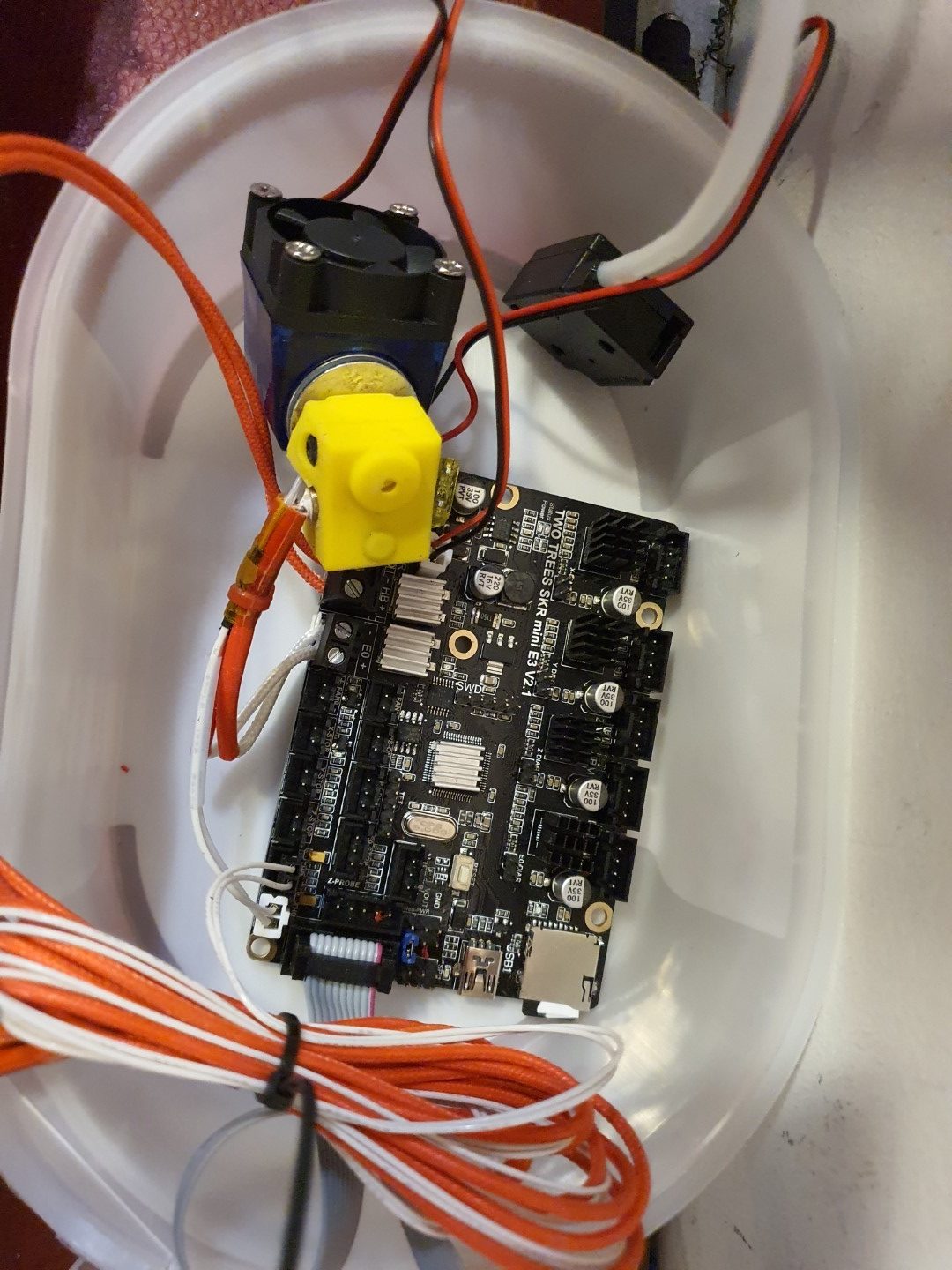
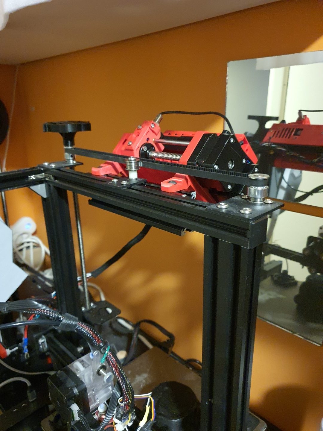
The motherboard that is also in the Ender3, SKR mini E3 V2.1. I used this setup to test the MMU hard- and software together with the SKR mini E3 motherboardThe MMU2S on top of the Ender3, just next to the 6mm belt that connects both Z-leadscrewsThe bondtech Prusa MK3S hotend/extruder combination, mounted on a 2020 mounting plate for the Ender3
There is a firmware version for the SKR mini E3 V2.1 on Github that makes use of the MMU2S. I downloaded this version and uploaded it to the board via visual studio code maker, all works well in the test setup. Some tweaking was needed in configuration.h and in the advance config, since I am using the S-version of the MMU2 and the filament sensor was not standard ON. And- it appears that the communication port needs to change to the 2nd port. You can see it all at the Reddit page, the additional changes to the published config files are these (thnx to fixel112):
Excerpt from Configuration.h:
#define SERIAL_PORT -1
#define SERIAL_PORT_2 2 <————— This has been the issue. Uncomment that line.
#define BAUDRATE 250000
Excerpt: Configuration_adv.h
#if ENABLED(PRUSA_MMU2)
// Serial port used for communication with MMU2.
// For AVR enable the UART port used for the MMU. (e.g., mmuSerial)
// For 32-bit boards check your HAL for available serial ports. (e.g., Serial2)
//#define MMU2_SERIAL_PORT 2
#define MMU2_SERIAL MSerial2
//#define MMU2_RST_PIN 23
// Enable if the MMU2 has 12V stepper motors (MMU2 Firmware 1.0.2 and up)
//#define MMU2_MODE_12V
// G-code to execute when MMU2 F.I.N.D.A. probe detects filament runout
#define MMU2_FILAMENT_RUNOUT_SCRIPT “M600”
…
#define MMU2_DEBUG // Write debug info to serial output
#endif // PRUSA_MMU2
Next is to put everything physically on the Ender, and exchange the hotend/extruder. Then, the settings for the extrusion lengths will have to be determined. And- the buffer for the filament between the MMU2S and the filament spools has to be installed. As soon as I have it all properly installed, more pictures will follow!
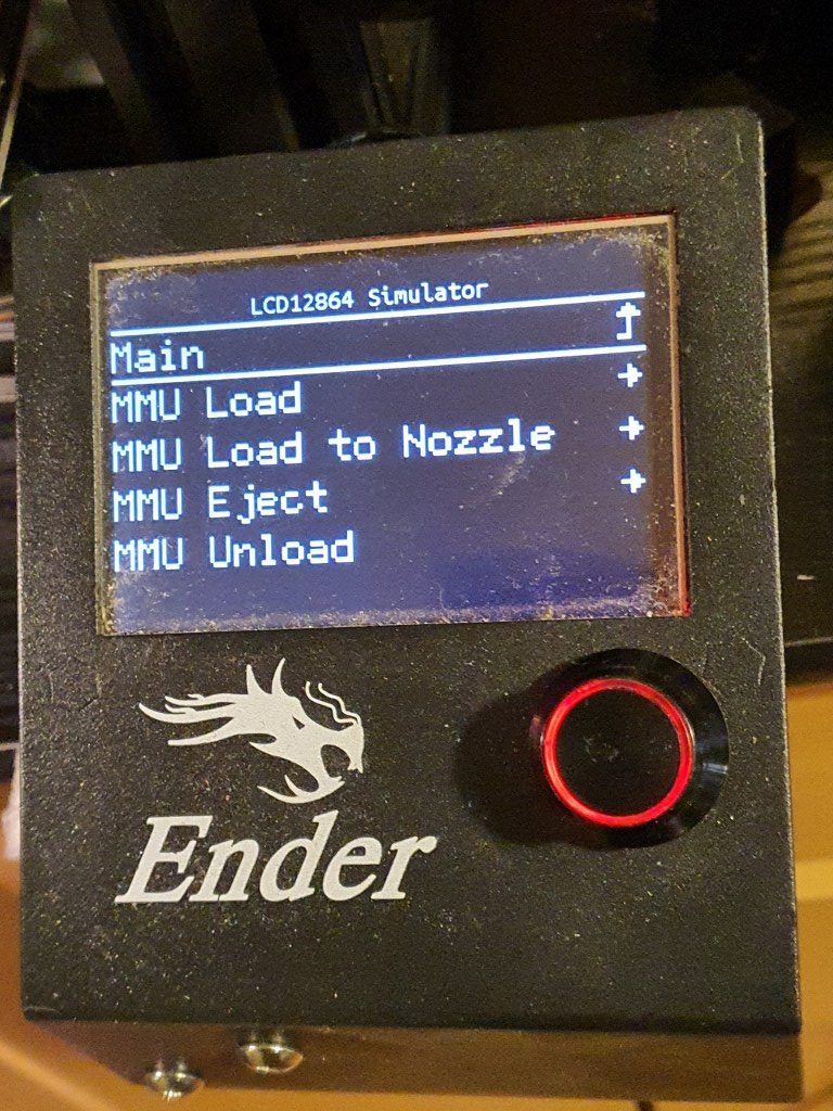
I discovered that the dual display I now use for the Ender3 will only work for Marlin LCD and no longer for TFT, since the serial TFT pins will be used to drive the MMU2S unit. I exchanged the TFT/LCD unit with the original Ender3 LCD, I kept this in storage and tested it today with the Ender mini E3 V2.1 , it works very well!
The twotrees SKR Mini E3 V2.1 motherboard is really perfect for the combination with the MMU2S and the new filament sensor in the new hotend/extruder. The firmware has been updated to include the MMU2S and the AUX’s serial that was previously used for the TFT screen is now in use by the MMU! It all works!!!
Now the next thing was to get the new extruder, F.I.N.D.A. and the filament sensr to work properly.
That took some time and next on the agenda is the filament management.
I already decided to go with the original Prusa filament box with plates to hold the retracted filament for all 5 spools. The spools themselves will hang at the wall, behind the printer. I don’t have space for standing spoolholders. Underneath the spools the filament box with plates gets its place on the wall and from there the 5 PTFE tubes will run to the MMU!
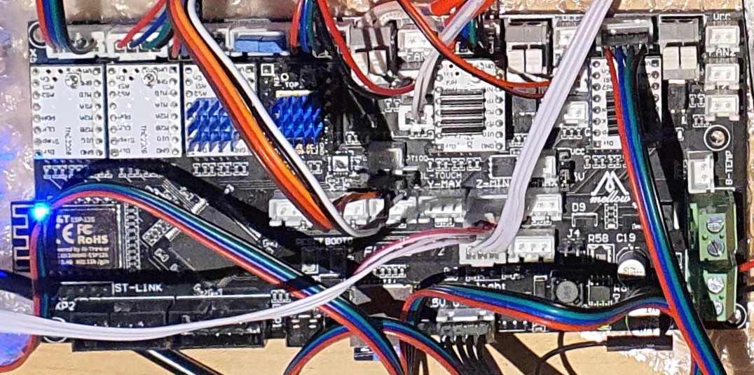
recently (3-2021) I have been setting up my new 3d printerboard from Mellow, an STM32 board that is named FLY CDY V2. It is (almost) fully compatible with Duet2Wifi and also uses its wifi-based 3d printer management system DWC.
The FLY_CDY_V2 board comes completely empty so I added the firmware.bin in the /sys directory, after I had an empty SD card filled with the clean reprap directories and -files.
Next to the firmware.bin. also a board.txt is required to be available in /sys with some settings, with the following content:
//Config for fly-CDY board = fly_cdyv2 led.neopixelPin = D.15; //wifi pins 8266wifi.espDataReadyPin = E.10; 8266wifi.TfrReadyPin = E.12; 8266wifi.espResetPin = E.11; 8266wifi.serialRxTxPins = { D.9, D.8 }; heat.tempSensePins = { B.1 , A.3 , C.4 , D.14}; be aware that D.14 is not a temp pin but a heat pin, is this wrong?? stepper.numSmartDrivers = 6; serial.aux.rxTxPins = {A.10, A.9};
This board.txt is already OK for 2209 drivers and for the use of the neopixels output.
In the pdf that is provided by Mellow on the Github page for the reprap STM32 boards, section FLY-CDYV2, everything is explained as to get wifi up and running, configure config.g et cetera.
In my config.g everything needed to work properly is already done, as is with my board.txt.
I made the config for a.o. a Cartesian printer with single X,Y,Z steppers and a triple hotend with 3 extruders, 1 heater and 3 nozzles. Included is: Neopixels, BLTouch, 3 filament sensors on the X,Y- and Zmax inputs, active fans for hotend tool on fan1 and object on fan0 If so desired, sensorless homing is possible with the correct driver boards. In this version, 3 optical endstops have been used on inputs xmin, ymin and zmin. Retraction is set OFF in this firmware by default, but may be swiched ON to make the triple hotend drip less (2 mm retract and -0.5 extrude without Z-hop), do experiment with these settings! Please be aware that some pin names for the FLYCDYV2 board differ from the Duet’s naming convention like “bed” versus “bed-heater” et cetera. Plus, some typical Duet2wifi extensions are NOT available like the GPIO bus. The FLYCDYV2 has some interesting standard extra’s though, like the BLTouch connector with power, driver pins and Z probe pins, the Neopixel connector AND the 6 driver slots and 3 extruder heaters/sensors/fans! It is quite simple to change this setup to a dual Z axis with independant Z-motors and either single extruder or a dual setup, single or dual nozzle, mixing or non-mixing. Please see my complete ready-to-go config directory setups for this board HERE to get you started!