

My experiences with CoreXY printers are excellent, so I chose a VORON for my home-built COREXY printer with a print size of 300x300x300 mm.
Developed from a large community, the VORON is one of the best and most reliable 3D printers. And this printer just looks really good!
Via AliExpress, Banggood, Reichelt, aluminiumopmaat.nl and plexiglas.nl I ordered all the stuff, according to the bill of materials I could download from the VORON site.
I printed the PETG parts on the Prusa mini at 0.15 fine.
The ABS parts (red and black) were printed on the Twotrees Sapphire plus. It took a lot of ‘tweeking’ before the ABS came out well but in the end I got a nice result!
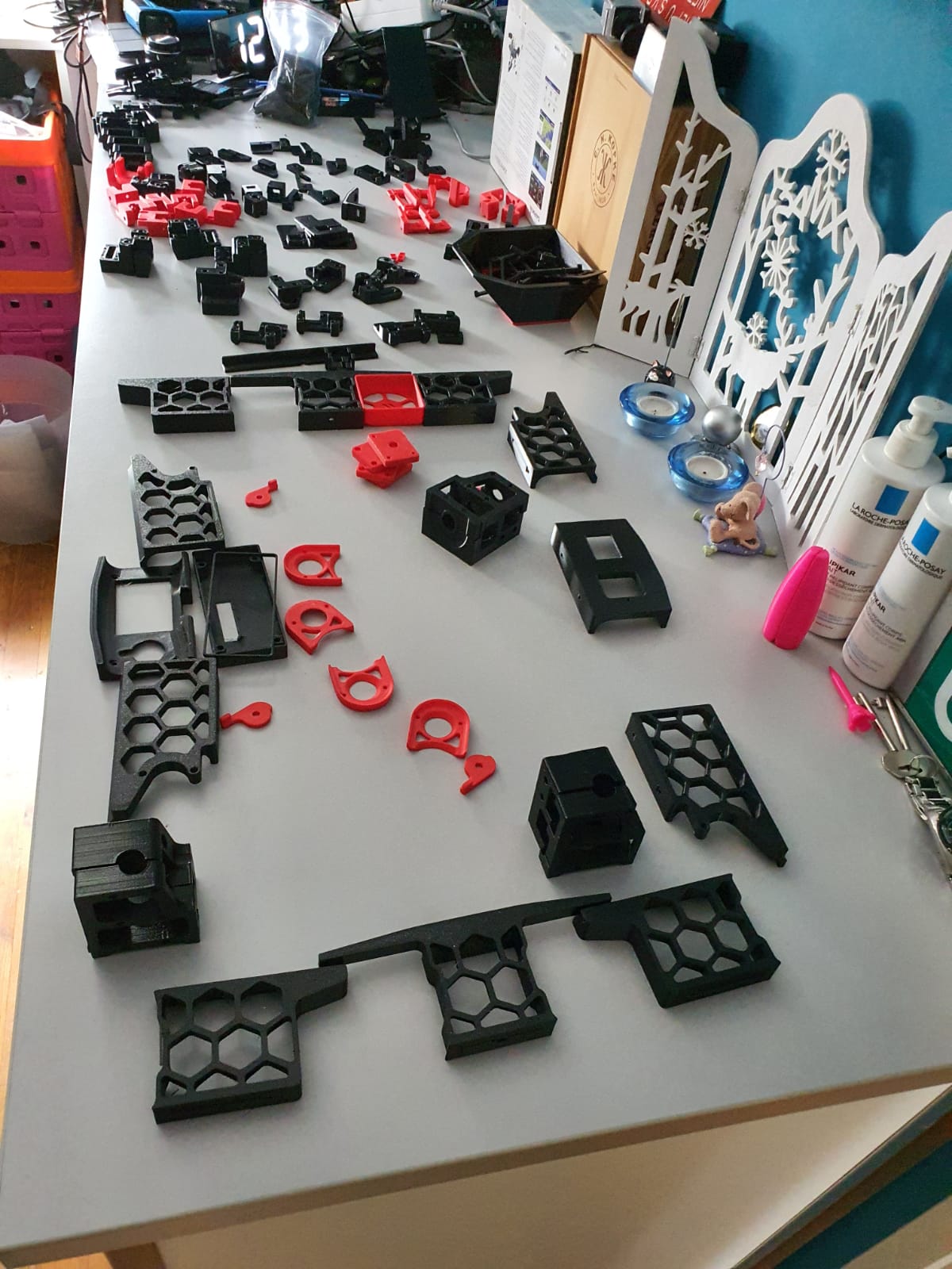
Printed parts for the Voron 2.4 300In the end, rebuilding is not really self-building and it is more based on ordering and assembling than getting to work with the saw and drill yourself. Also the necessary 8(!) linear rails of 350mm, bearings, gears, belts, motors, electronics and so on have been ordered and the rest of the necessary stuff has been printed (25-8-2020).
For the control part I have chosen one PI Raspberry PI 4B 4GB and two pieces of SKR 1.4 turbo motherboards, according to the VORON recommendation.
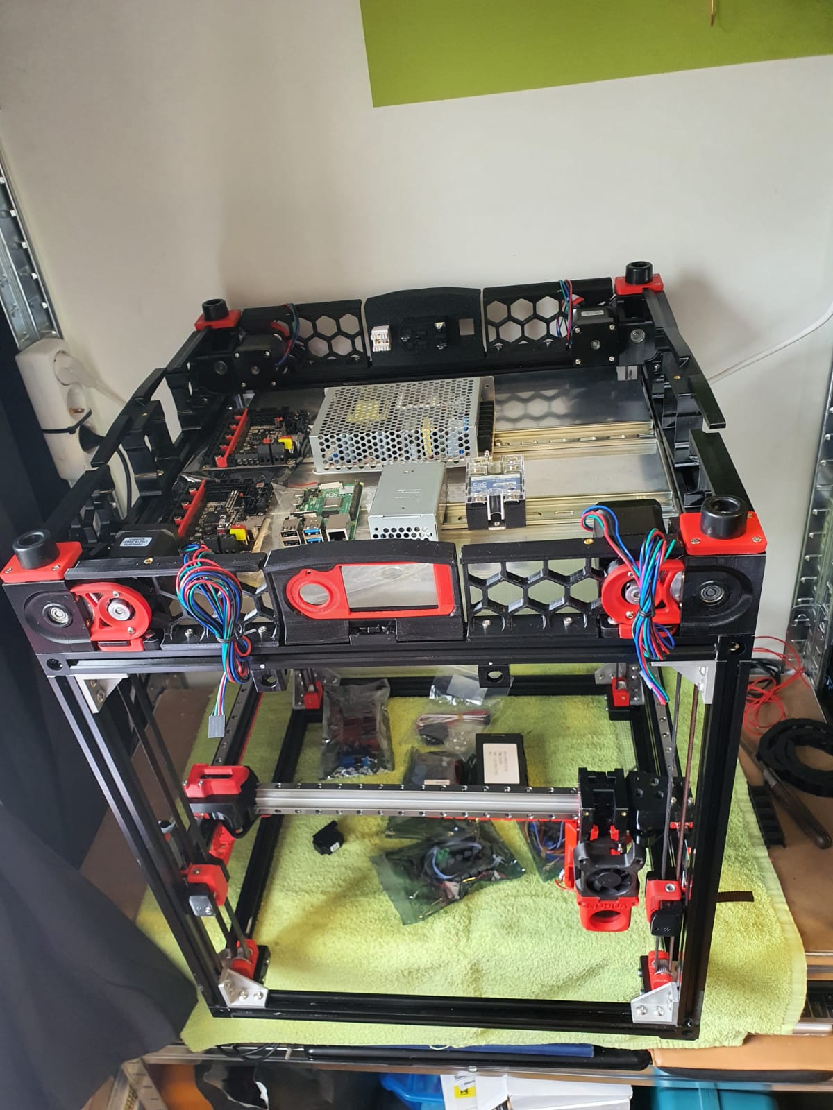
Building the Voron 2.4 with the afterburner Beta1 hotend combination is illustrated by the following pictures.
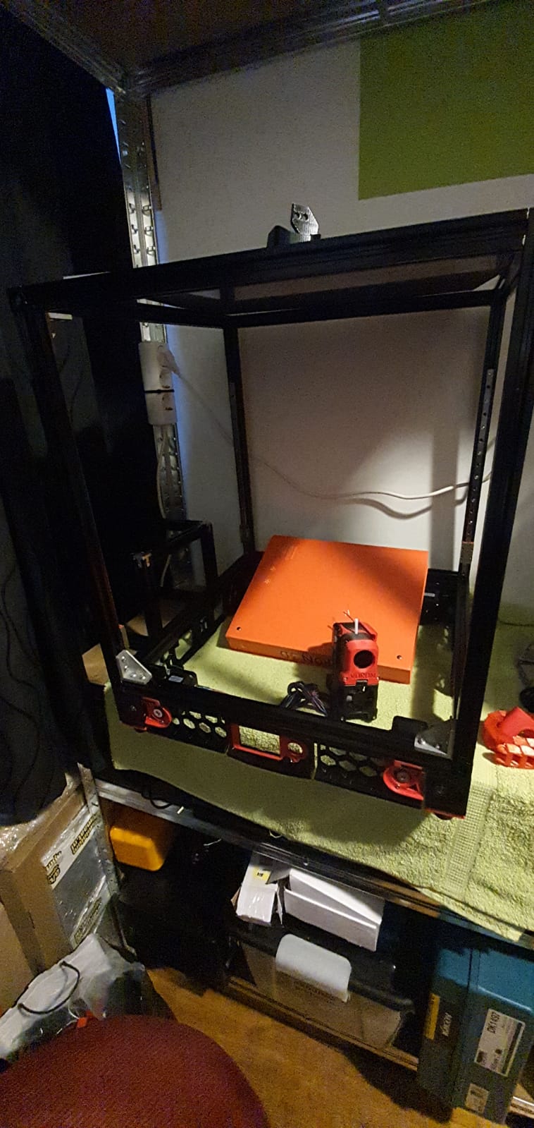
Gantry ready:
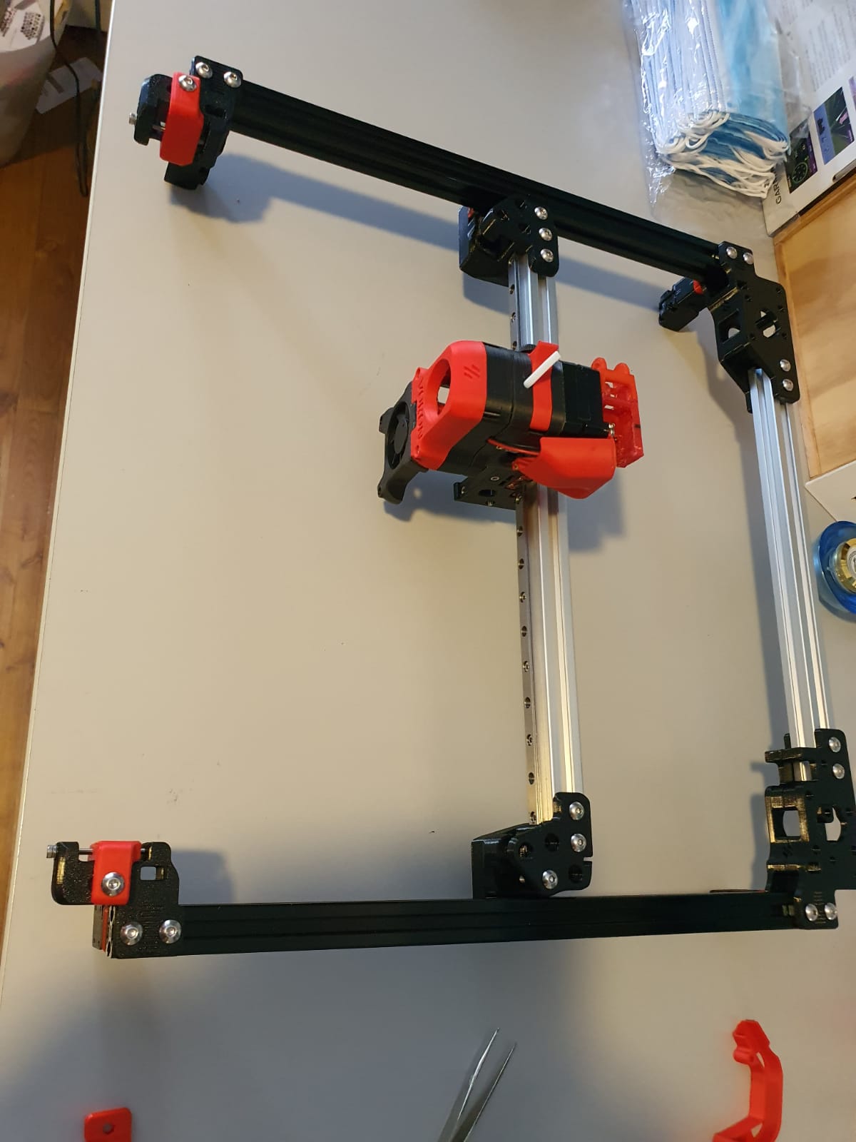
Gantry of my Voron 2.4 300Housing and skirts underside with Z-motors yet without the gantry mounted:
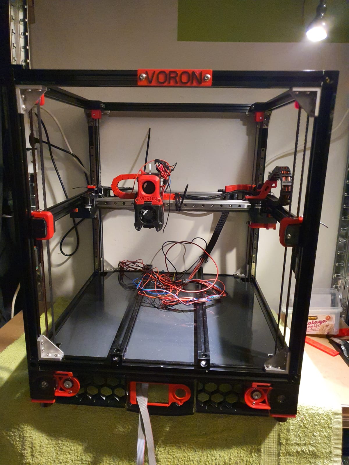
Below: The 9 mm drive belts of the 4 Z-axes placed:
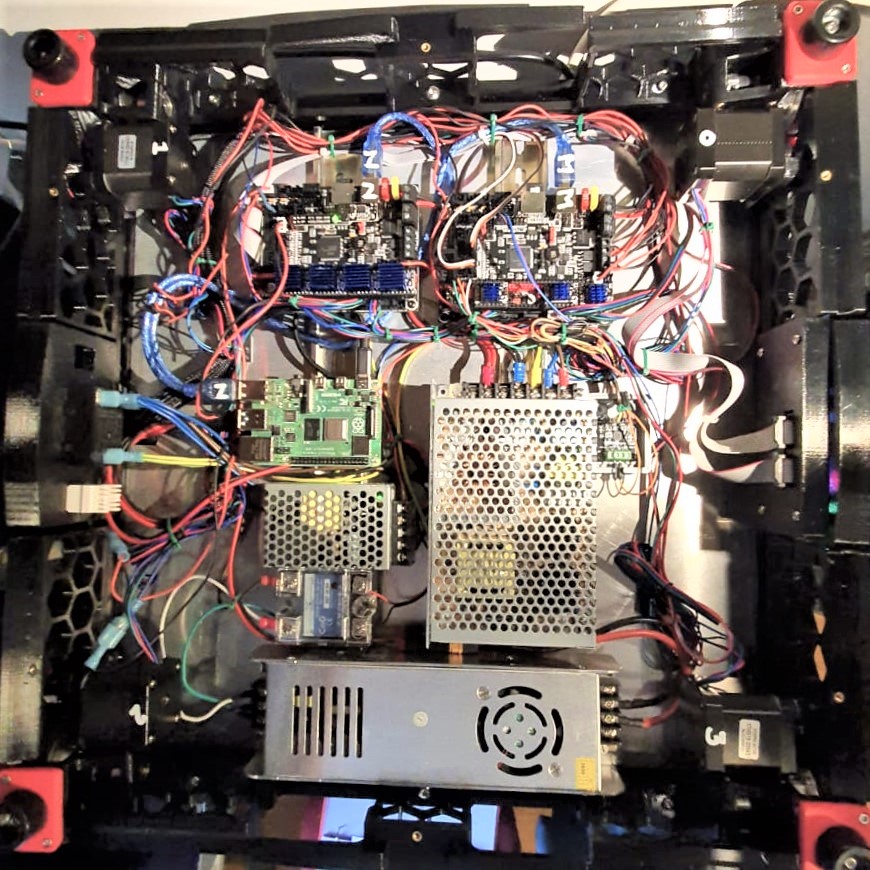
And the assembled base plate with the rails and controls, power supplies and so on (printer turned over):
We are still waiting for the bearings for the Alpha and Beta drives in the gantry. These bearings are used to make a tension roller per 2 pieces. I had originally bought idler bearings for this purpose, but the diameter of the collar of these bearings is just too large.
Too bad but then I have to work on the Raspberry PI4B in combination with 2 times SKR V1.4 turbo motherboards. The PI will make a new config.bin via Klipper for the SKR V1.4 motherboards so the PI can drive both SKR boards at the same time. On the main board will be Alpha and Beta and the extruder plus the extruder heater, on the other (Z) board the 4 Z-motors and bed heater. By itself a Duet with expansion board could have been an option too, but the Voron designers made it with the PI, Klipper and 2 SKR boards. And I try to stay as close to the design as possible . -)
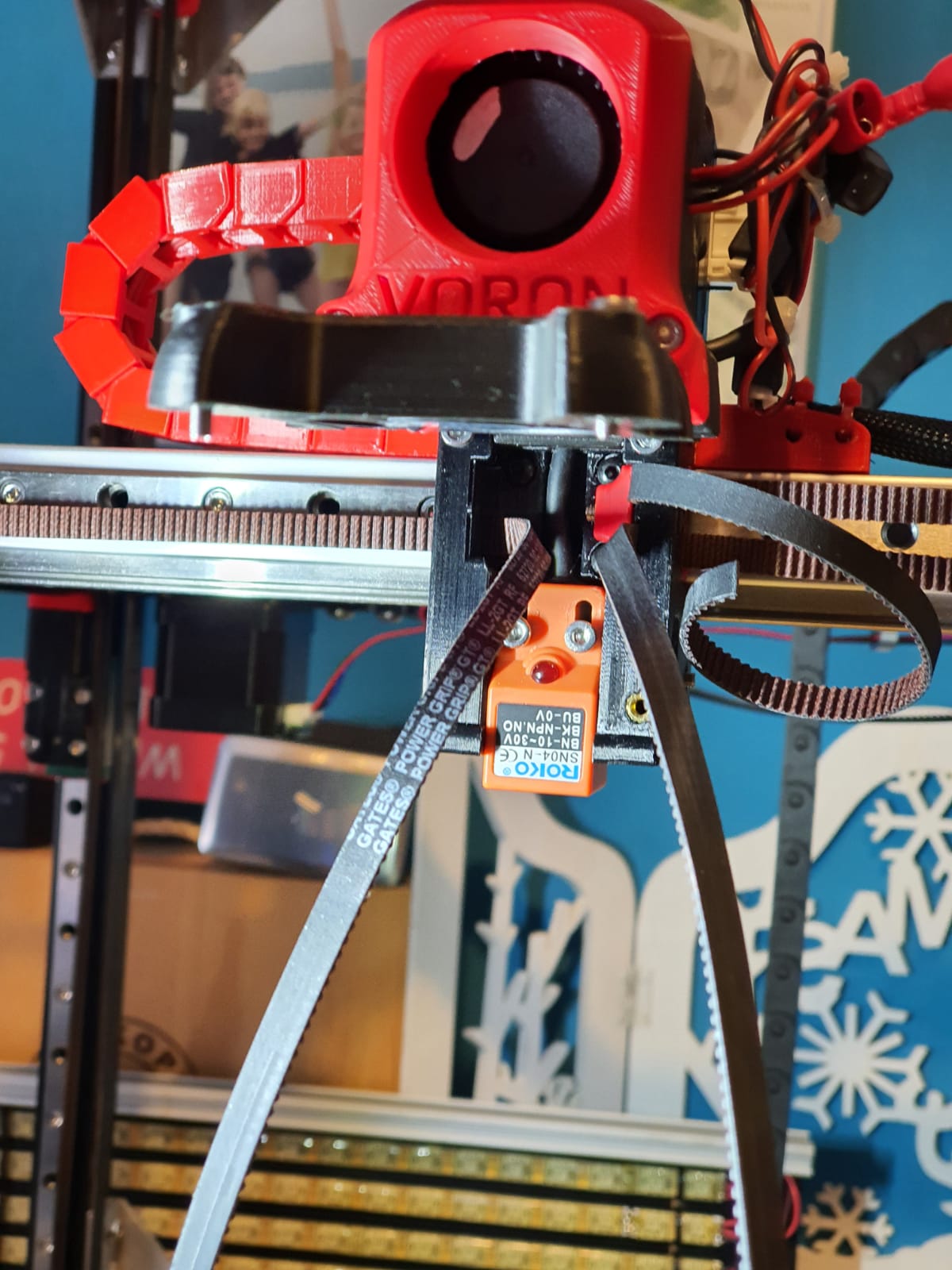
Below: Threading the straps, no picture used. Just start somewhere and you’ll end up right. Oh yes, also changed the sensor in the config from NC to NO..
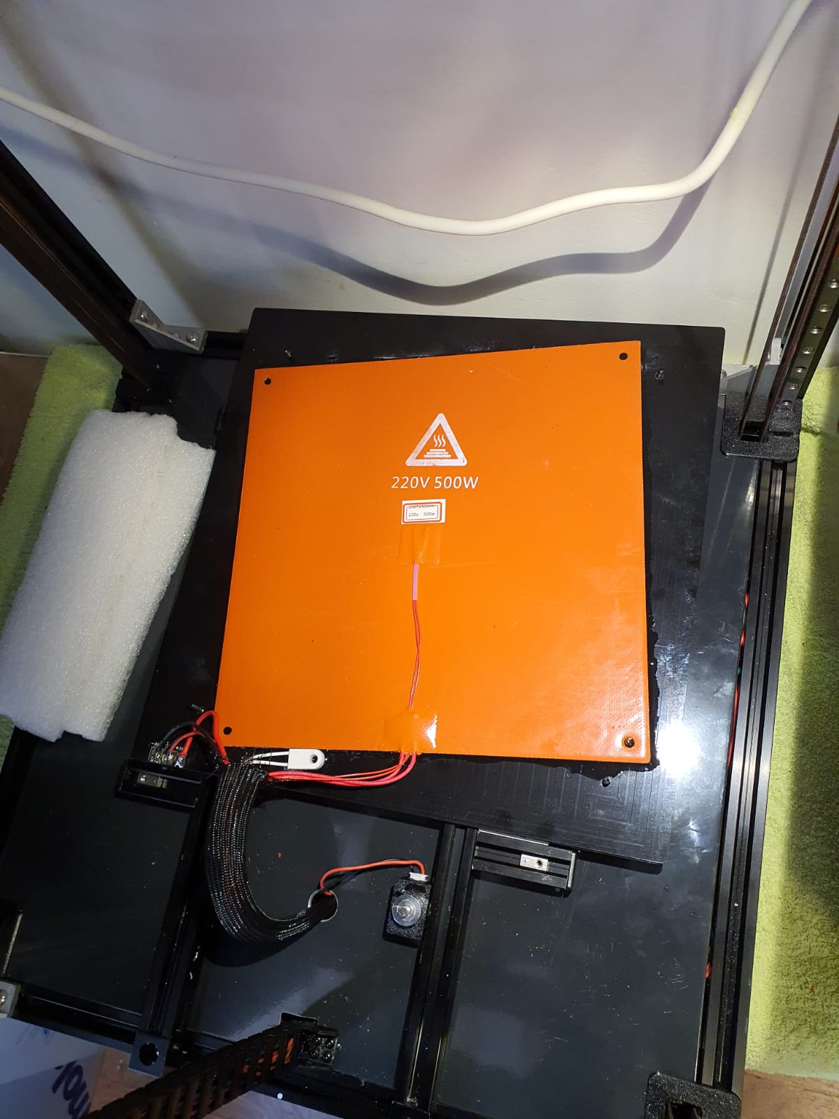
Below: In addition to the 24Volt 200 Watt hotbed nevertheless also added the 500 Watt 230V. With only the 24V version it took more than 20 minutes to get to 110 degrees Celsius…
Old:

And new— no PID run done yet..)

Below: The steel plate is placed on the sticky magnet sheet.
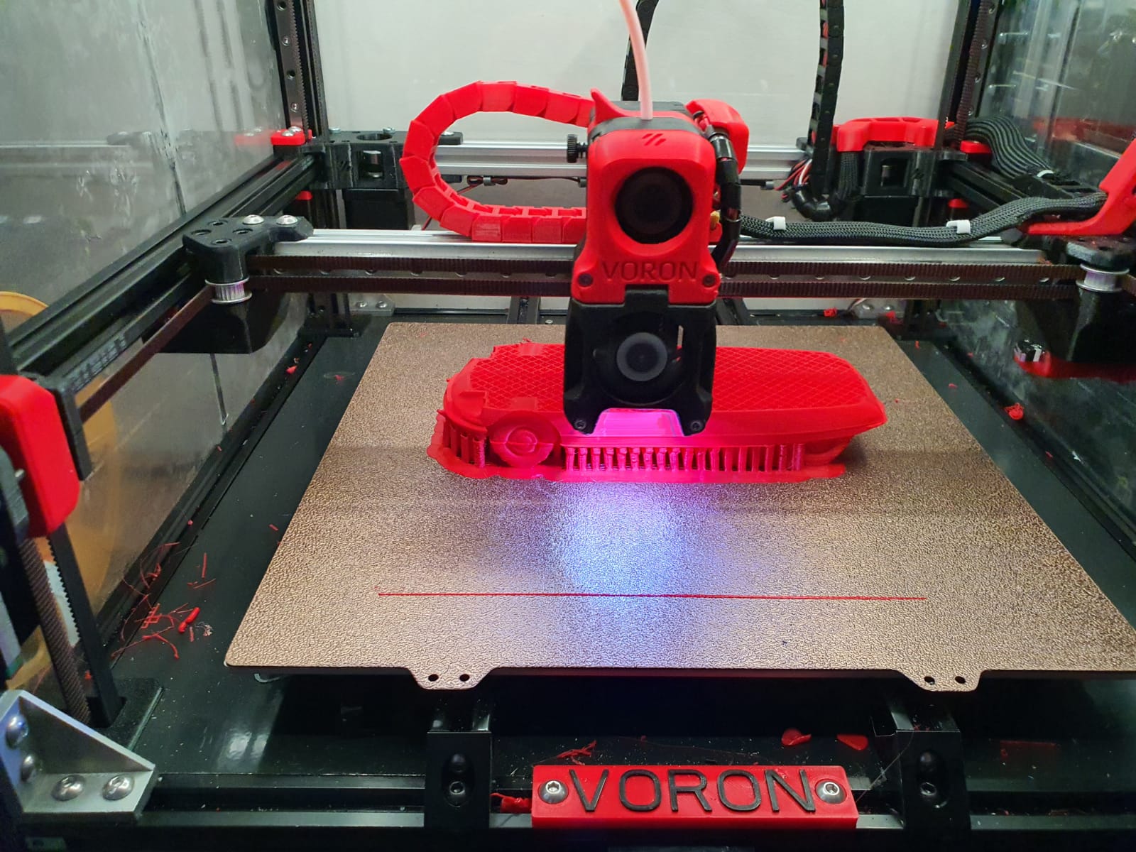
Below: First print…. I had to search for the Z offset adjustment and the extruder turned the wrong way around. Also the gantry leveling took some thought, you actually have to make the basic setting with a ruler, otherwise the leveling takes a long time. Nice is that a bed mesh leveling is not necessary anymore, but of course it can be done. You turn a home and because the nozzle always calibrates the Z on the mechanical Z endstop, and the gantry does all the leveling, you always have a good first layer. Unless the bed warps but with such a thick plate that seems almost impossible. Just to be sure, I did include a bed_mesh profile in the config.g. By the way I just used a 24 V aluminum hotbed as a base because my 8 mm 310×310 plate turned out to be a cut plate instead of sawn. And a cut sheet turns out to be non-flat on the cut sides by default, unfortunately. Flattening costs more than a new plate, maybe that will come sometime….
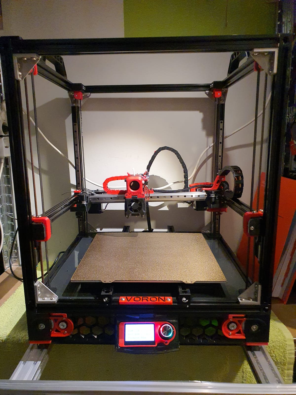
And with enclosure, camera and the TOP LED’s:
Afterword:
In practice, I fixed a few more minor flaws, including:
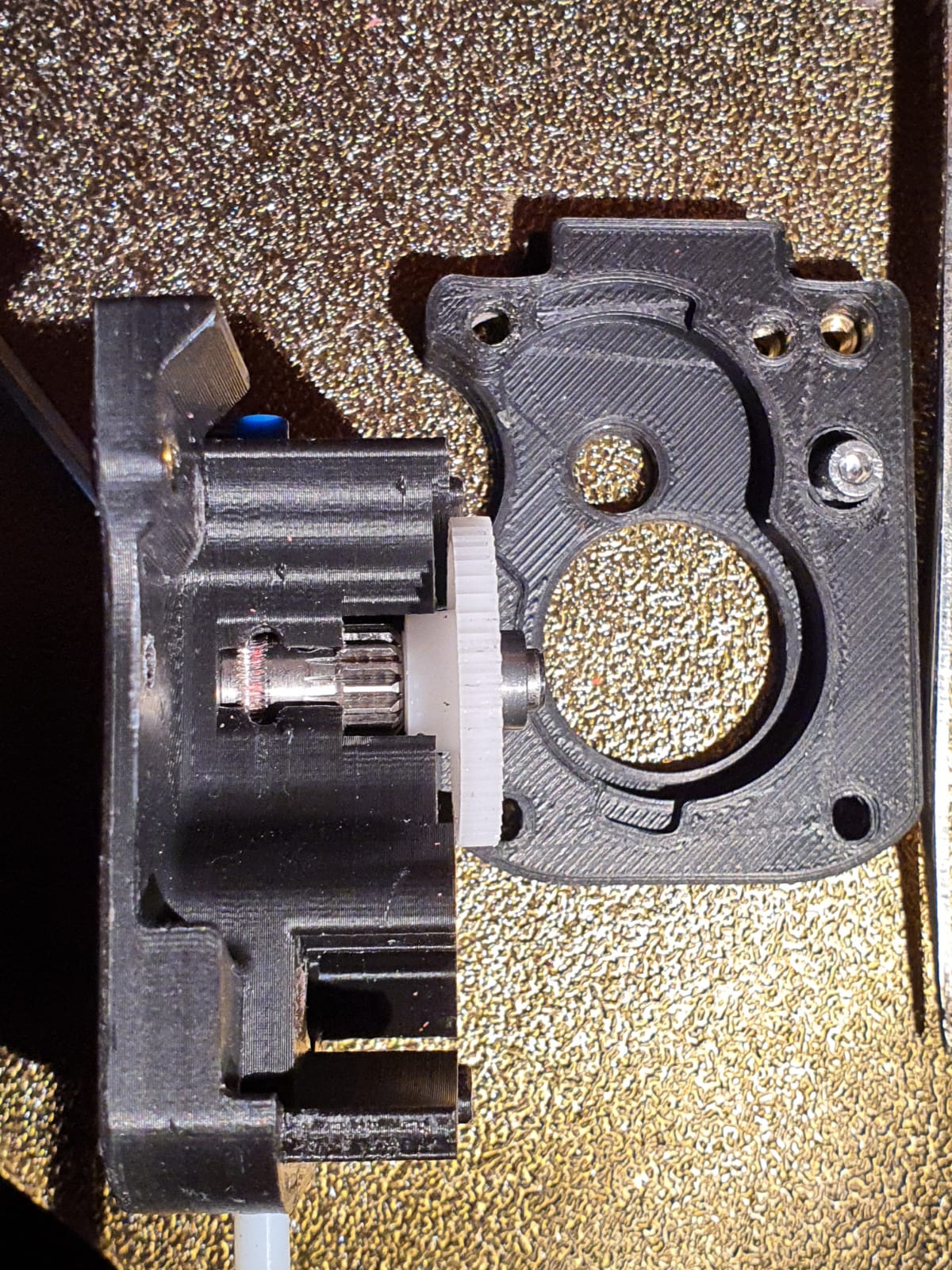
Extruder tuning. The donor extruder turned out not to pick up the filament properly.
First I tried to put a ring in between the left side of the shaft, but then the nylon gear on the right side of the shaft gets tight and the housing can’t be closed completely anymore….
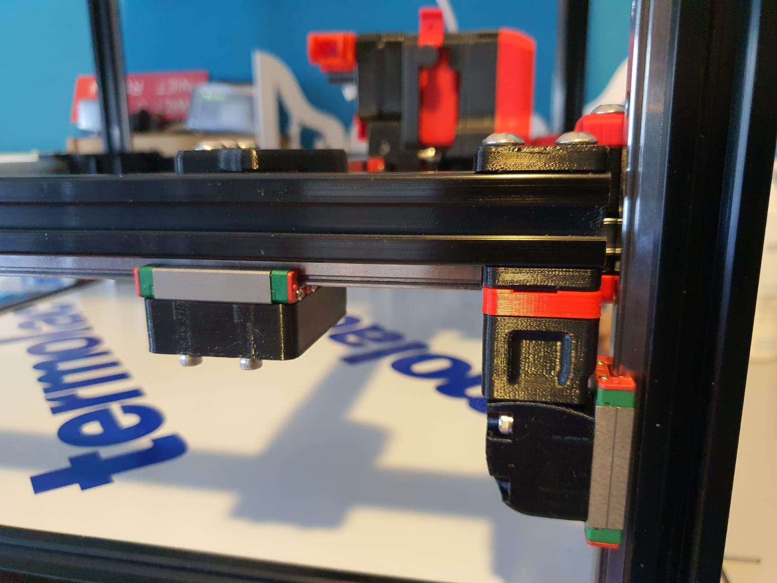
I ended up using a spare set of dual drive extruder gears and swapping the set of gears. With that, the filament was properly aligned with the running path of the gears. See the picture how it was at first:
Hotend tuning
After the PID runs of hotend and heated bed, my chosen assembly of the custom ED6 heater block, the heatbreak pipe and the cooling element turned out not to fit together properly. The result was that when the filament was extracted, a thick piece was always stuck at the end. This was caused by the heatbreak pipe not fitting tightly on the nozzle. There should be no play between them. I completely demounted the filament and screwed the heatbreak pipe 2 turns less into the cooling element with red threadlocker. Let it harden for a day and then I assembled the rest. By the way, I also mounted the teflon version of the heatbreak pipe in stead of the titanium version. The tintanium version was to my experience a bit too stiff. Or my filament was too old or inferior. In any case, after the modification, everything works without problems.
Hotbed, TPU and ABS
To print TPU and ABS without brim or skirt without warping I bought a magnetic PEI steel plate with coarse profile. It really works perfectly. Both ABS at 110 degrees sticks nicely and TPU at room temperature sticks nicely too. And the removal is also without problems. Occasionally I spray a little hairspray on the plate but I don’t think that lacquer is really necessary at all. It is meant to make the removal easier.
Tension of the belts
I tried getting the belts at the same tension, this was not that easy. Finally I ended up with a mechanical way of measuring tension after putting 1 at my desired tension and comparing this as reference with the other to be compared belts. So, for the Alpha and Beta belts I first did a ‘good feeling’ setting and then I used my old trunk scale weight device to measure the tension when pulling the belt A. Then, I used the device to measure at the same place for B. And I repeated this for the 4 vertical belts.
Alignment
Aligning the machine is also a bit of a challenge…
You must assume that your frame is square and straight. You have to check this thoroughly. Both vertically, horizontally and diagonally. Then you can adjust the gantry. Loosen and remove the A and B belts. Or do the alignment BEFORE placing the belts.
Fix the horizontal position of the Gantry otherwise you can’t align at all. Place 4 equal distance blocks of about 10-15 cm under the sliders of the vertical linear rails on the lower 2020 profiles, in the 4 corners through which the gantry rests stably. I have placed position holders under all MGN9 vertical linear rails afterwards so that the rails cannot slide in the 20×20 V profile. If you use ‘regular’ 20×20 extrusion profile you don’t have a problem because there is enough ‘meat’ left for attaching your rail to the profile. With V-profile, the groove is a bit wider and it is very difficult to mount the rails neatly without tools in the groove. My frame is of V-rail profile and the gantry of plain 2020 profile.
The alignment of the gantry I started at the back. Loosening all screws a bit, including the screws of the convex connectors that hold the gantry to the linear rails. By the way, I see some builders placing these screws with multiple spring washers. I’m going to do that too…
At the rear of the gantry, push the gantry completely against the rear. There should be no gap between the XY joints and the frame. PS: Leave the endstops off for a while at this action!
While the gantry is sitting against the back, tighten the XY joints and the sliders of the X-axle as well. (the side of the endstops holder is temporarily secured with 2 screws)
Tighten the rear 2 gantry joints (with the convex surfaces) as well. This fixes the rear position at right angles.
Carefully slide the gantry forward. This should be possible without any effort. If not, check whether there is enough play (and if necessary loosen the screws) on the gantry joints at the front (with the convex surfaces). If you still don’t have a free run to the front, your frame is not good or your vertical rails are not seated properly. First check the correct positioning of your rails with your position tool (from the printed stock) and to be sure also unscrew the 4 screws on both front vertical rails. Try again if the sliding of the gantry goes smoothly. Still no good? Then reverse the procedure and start at the front. Try to set the gantry exactly level with the frame.
After adjusting: Test the alignment also halfway (vertically) and at the top!