Protected: Disc brakes for my Citroën Traction Avant


3D modeling, scanning and printing
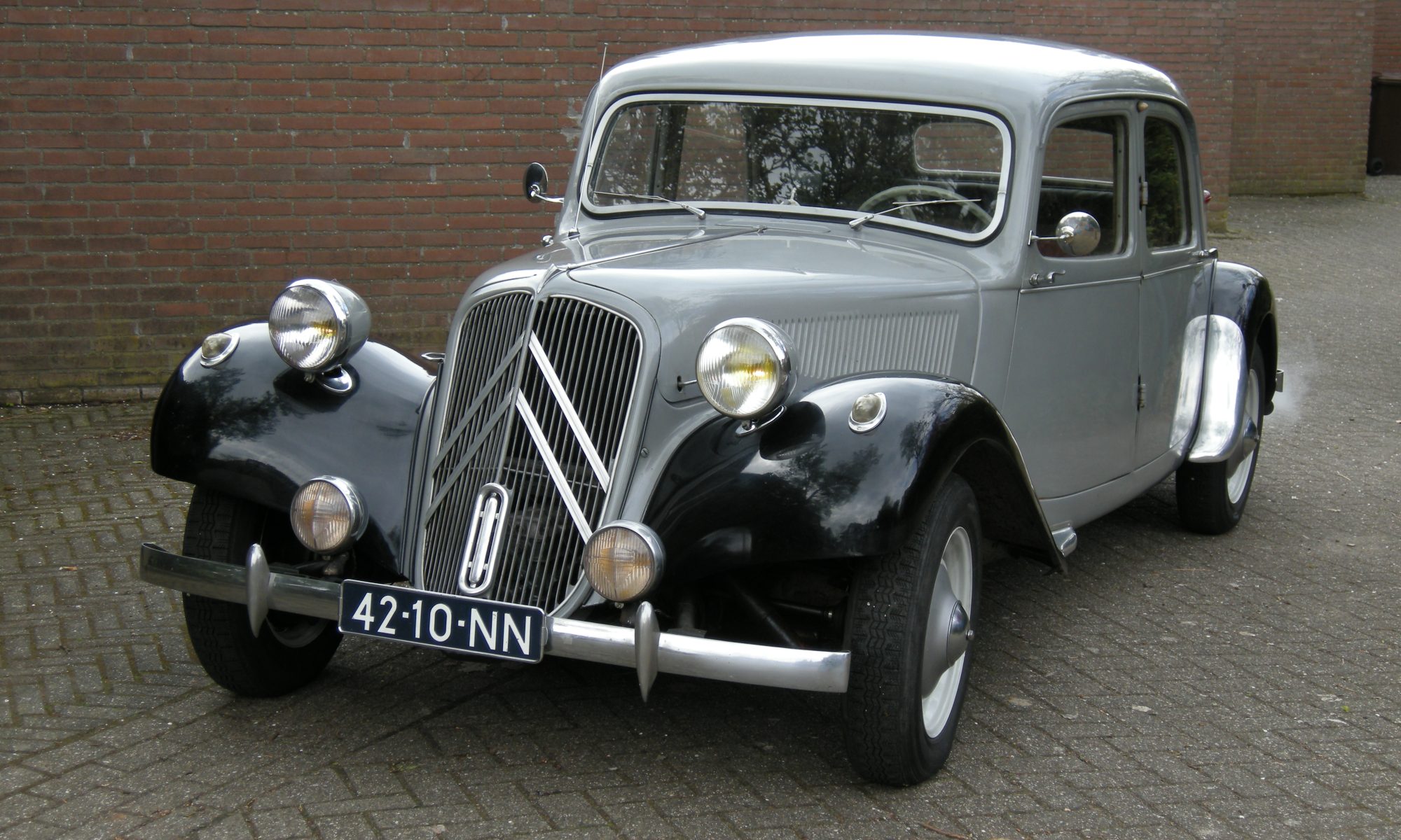
I bought my Traction Avant 11BN (1955 made) in june 2006, and I had to perform a lot of mechanical repairs before the car was roadworthy.

The engine block was cracked beyond repair, the gearbox 2nd gear was smashed, the brake system was really bad and so on. And the fenders were rotten in the common places. BUT- the body and the doors of the car were wonderfully intact.
AND- this car has had internal body care with either dinitrol or some other rust-preventing fluid. Everywhere the little plastic caps show where holes were drilled to gain acces to the car’s body for the rust prevention. One of the first things I have done is to do this process again, with solvent and rust preveting fluid, also on the bottom and underbody of the car.
Other parts were also renewed: Drive axles, steering joints, all lights like blinkers, head lights, dash, interior. Also the exhaust, gas tank, suspension dampeners, horns, steering wheel (temporary until the original steering wheel was repaired)
So- to get the car through the MOT inspection I initially made the mechanics work. Later on, I also made the car’s exterior look good. I chose to keep the internals of the car as they were, to preserve the vintage appearance.
The brakes, engine and gearbox were really bad and all had to be completely overhauled.
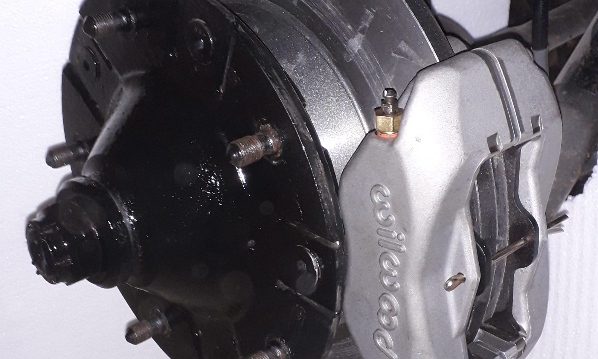
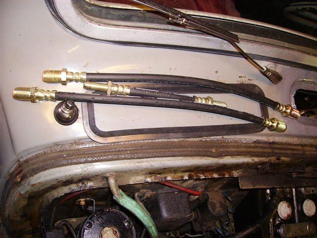
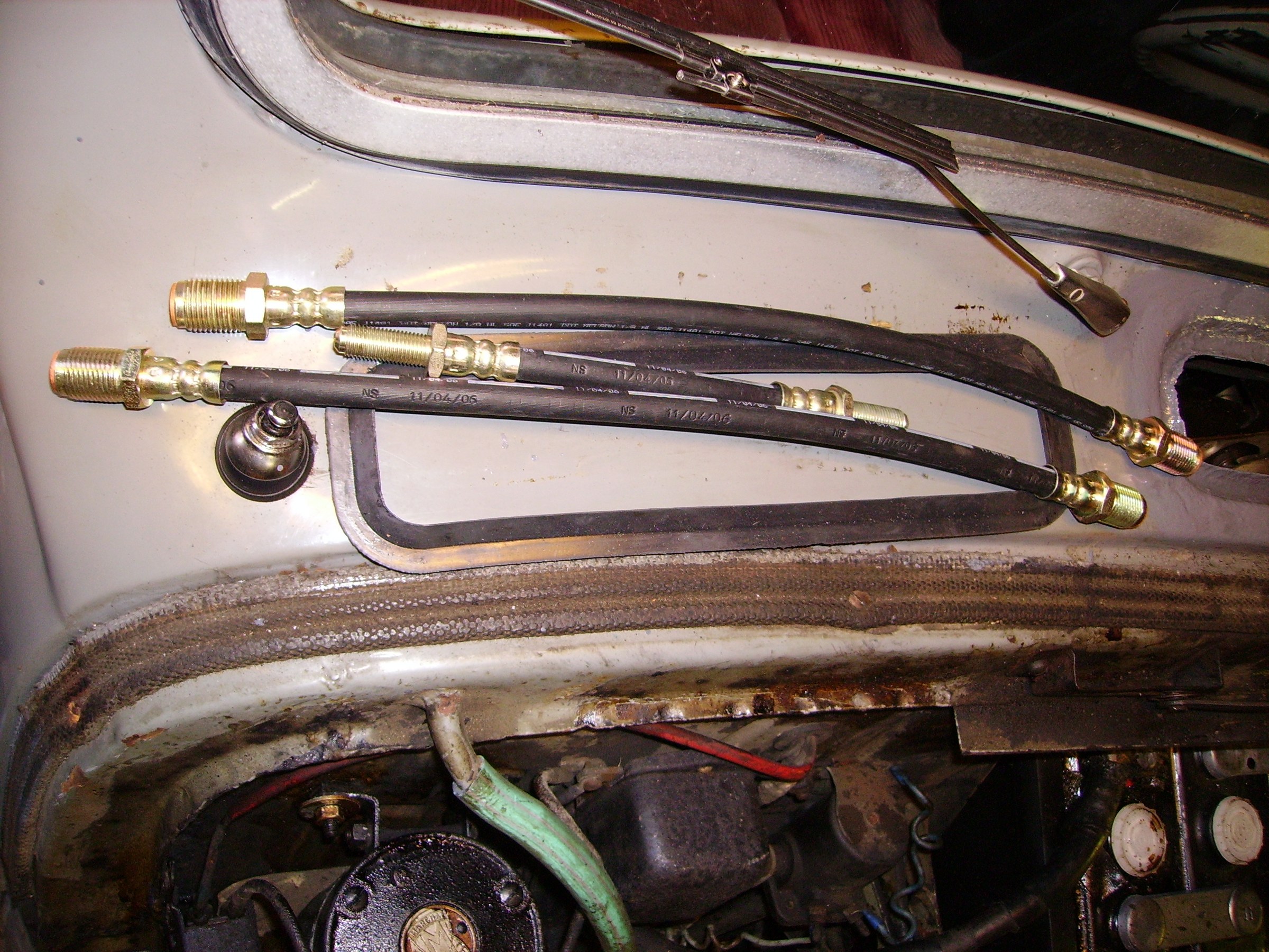
New brake calipers, new flex brake lines, overhauled master brake cylinder, changed to DOT3 brake fluid, new brake springs, new brake shoes and – retainers, new dust covers for everything
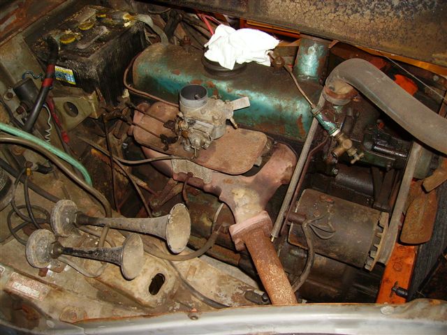
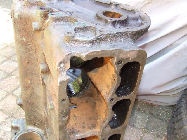
The engine was completely seized up. I had it soked in diesel for a week, took the carter pan off and freed the pistons. Bought a revised cylinder head and made the engine run again. Later, I found out that the cause of the seized up engine was a cracked underblock in the passenger’s side rear corner. But- the engine ran well again to get through the MOT.
The gear box of this car is a 3-speed, no synchro on 1st gear. It is a gearbox that is not regarded to be very sturdy and thia was my problem. Obviously, the previous owner tried to get the seized engine free by towing it in 2d gear. 2 teeth were broken off the 2nd gear teethed wheel. Fortunately, the TAN club could provide me with a 2nd hand 2nd gear teethed wheel and I repaired the gearbox, replaced it and we were almost done.
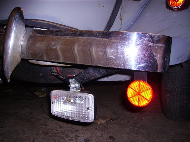
The rest of the repairs was a lot simpler like replacing the gastank, repairing all lights, repairing the original drive axles (I replaced these with unijoint versions later on) , hand brake cables, mirrors, and a lot more. Also, I had to add a red fog light at the rear.
REPAIRS
Directly after the MOT I had to do a lower motorblock exchange since the original lower motorblock could not be repaired.
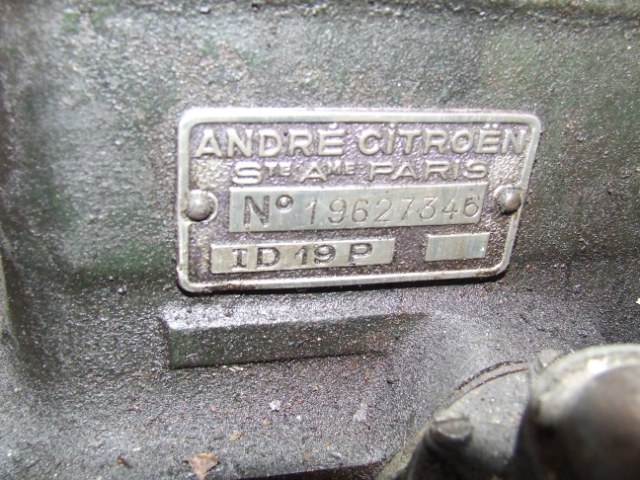
For this repair, I got me a long stroke Citroën ID19P engine underblock which is very similar to an original TA lower motorblock. This all worked very well with the original TA’s upper parts and during/after the first MOT I drove with this combination for a couple of years.
OUTER APPEARANCES
Although I fixed the outside of the car to make it through the initial MOT inspection, the car was far from beautiful. I just patched any holes and put some paint over it in a similar grey color paint.
It took me over half a year to get the car in a nice external state, by repairing all bad parts, doing metal- and bodywork and spraypainting only the repaired parts. In this way, I preserved over 60% of the car with original paint.
I had to do a lot of bodywork on the fenders, and some on the bottom of the doors, the raingutters of the roof, the outer parts of the bonnet, the edges of the rear window mount, the edges of the hood and the air inlet just under the front window.
UPGRADES
Later, I upgraded to the following parts (sequential order):
***: I mated the old 3-gear original gearbox to the old TA-motor that now has an ID19P underblock. This is now my spare motor/gearbox set in storage:
MAINTENANCE PHASE based on max 2000km/year
Every year:
PLUS Every 2 years:
PLUS Every 4 years:
Afterthought: I am glad that I am by now very experienced in doing all of my maintenance myself, and having a place to work with all the required special tools available helps a lot!
For things to come: Please see THIS
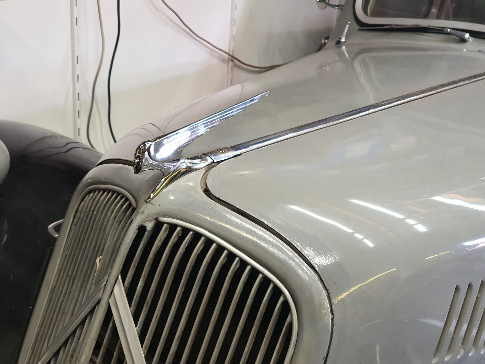
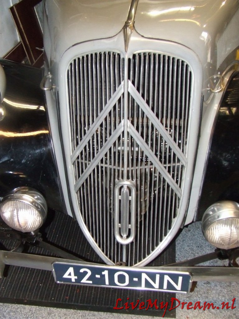
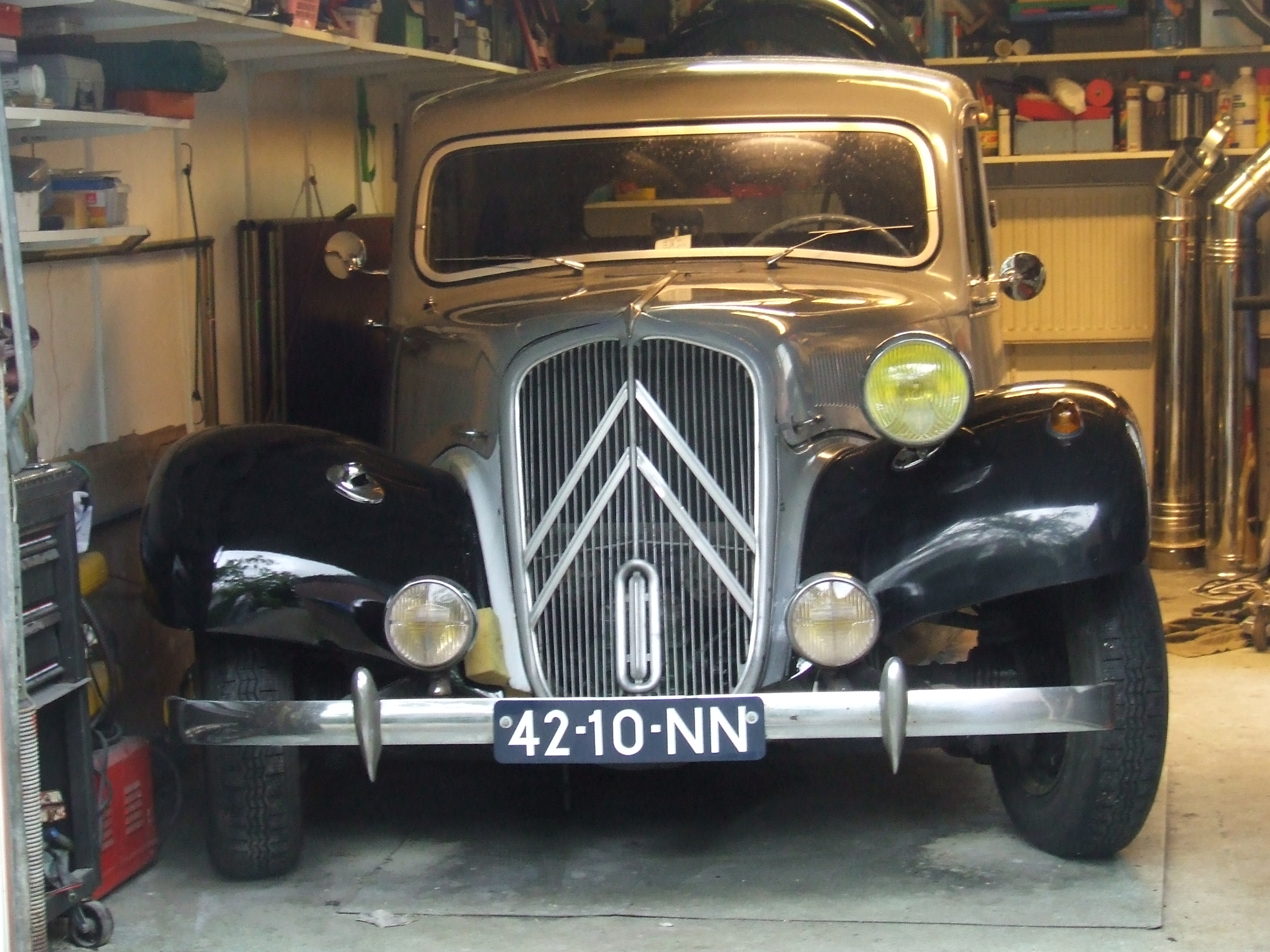
Now and then I check my preferred suppliers for the availability of a so-called ornement de capot, in French.
This is a hood mascotte, originally fabricated by ROBI for a.o. Traction Avant 11BN and BL.
To my surprise, Franssen in Belgium had a new stock of these for my BN and I ordered me one, it got delivered very fast and today I installed it.
It does only fit in 1 existing hole, so I needed to drill the front hole new.
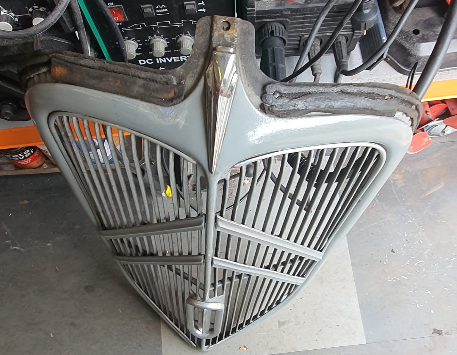
The radiator grill needs to be removed to do this.
I am very pleased with it!
It feel it matches my Traction with its repaired paint and original patina overall looks very well.
And suddenly the Traction Avant wouldn’t start.
It had been struggling a few times, as if the battery was dead but it was nicely full.
And suddenly just a click instead of a running starter motor.
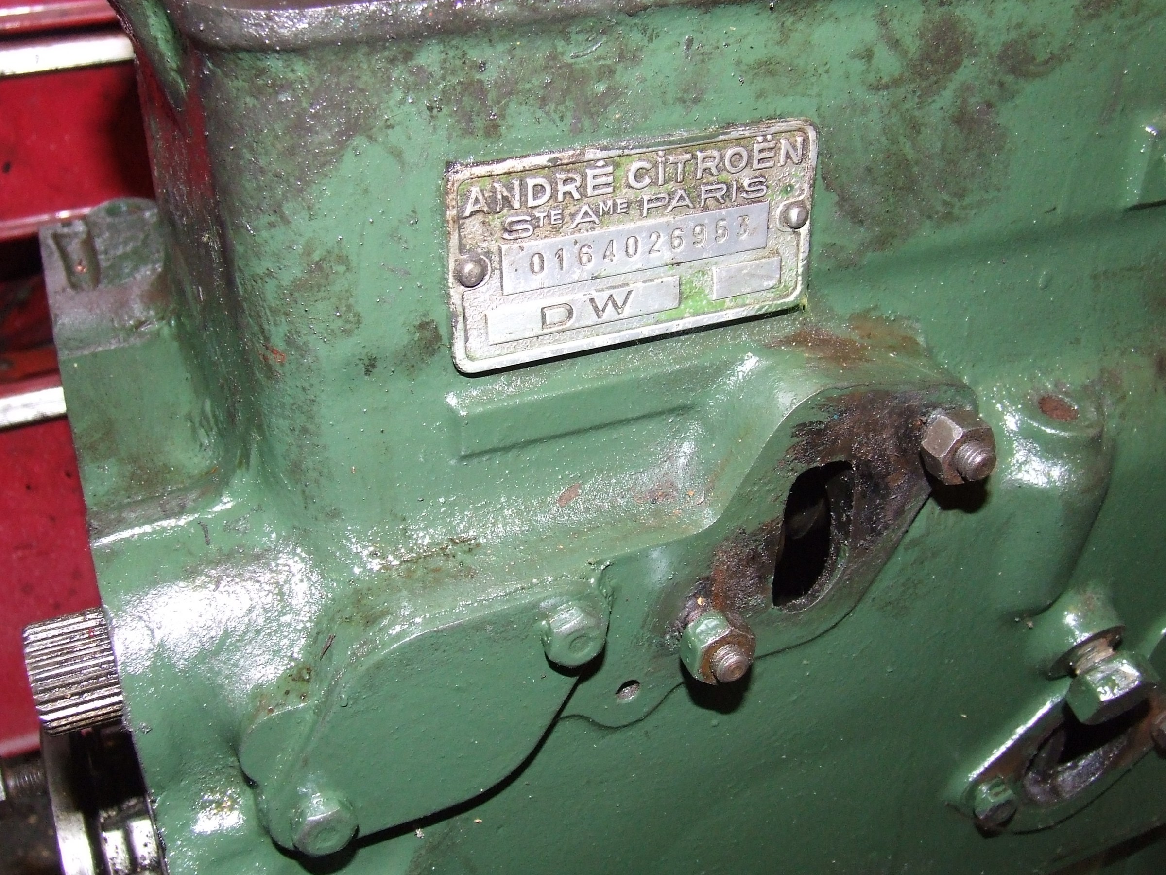
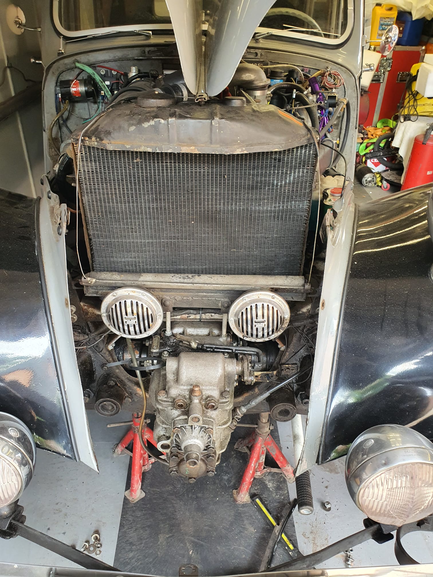
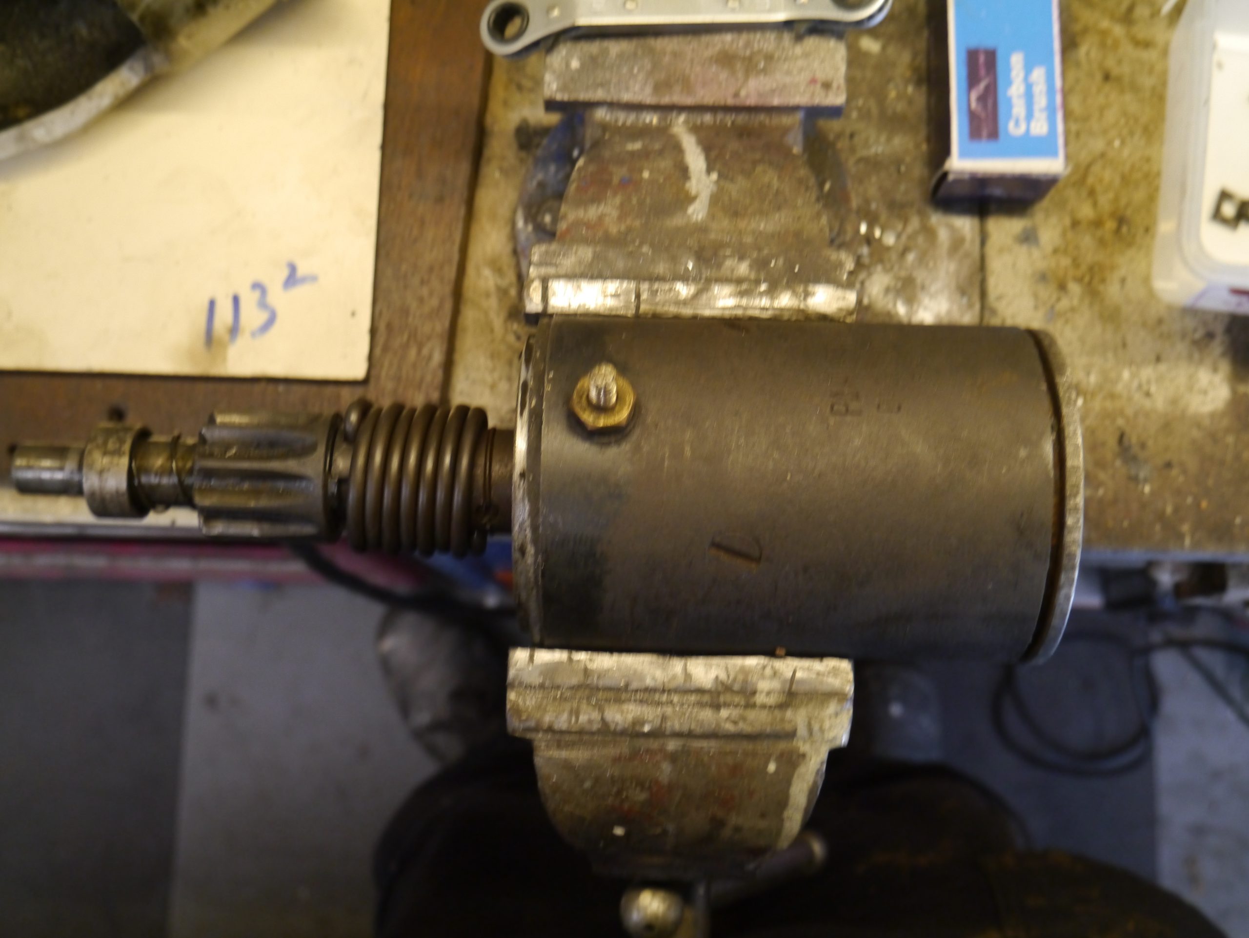
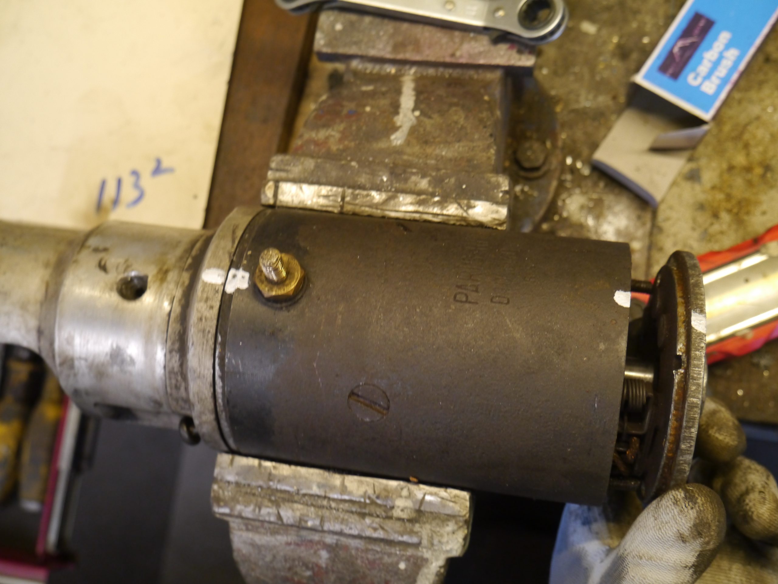
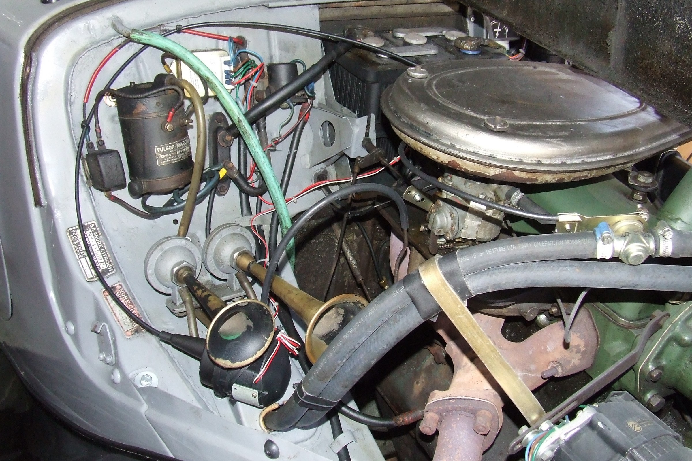
I have a Paris-Rhone 12V ID starter motor in my Traction Avant
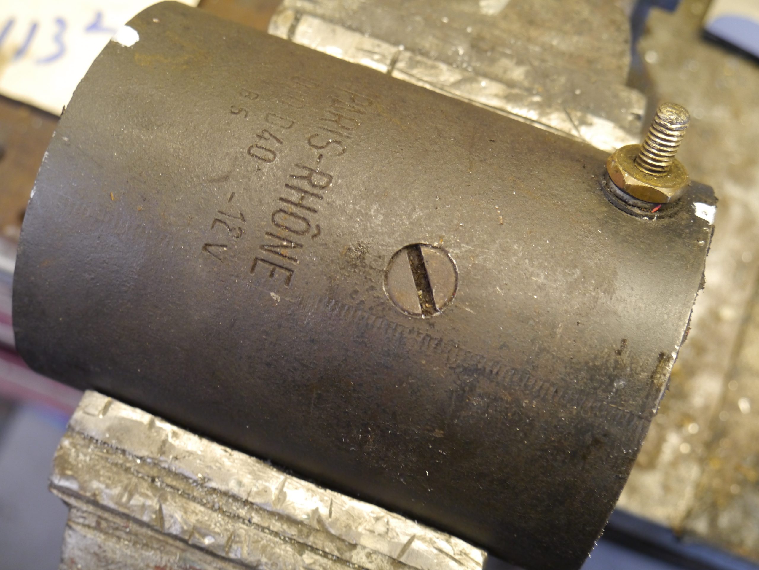
-which fits the flywheel of my long stroke Citroën ID (DW) engine once mounted in the TA.
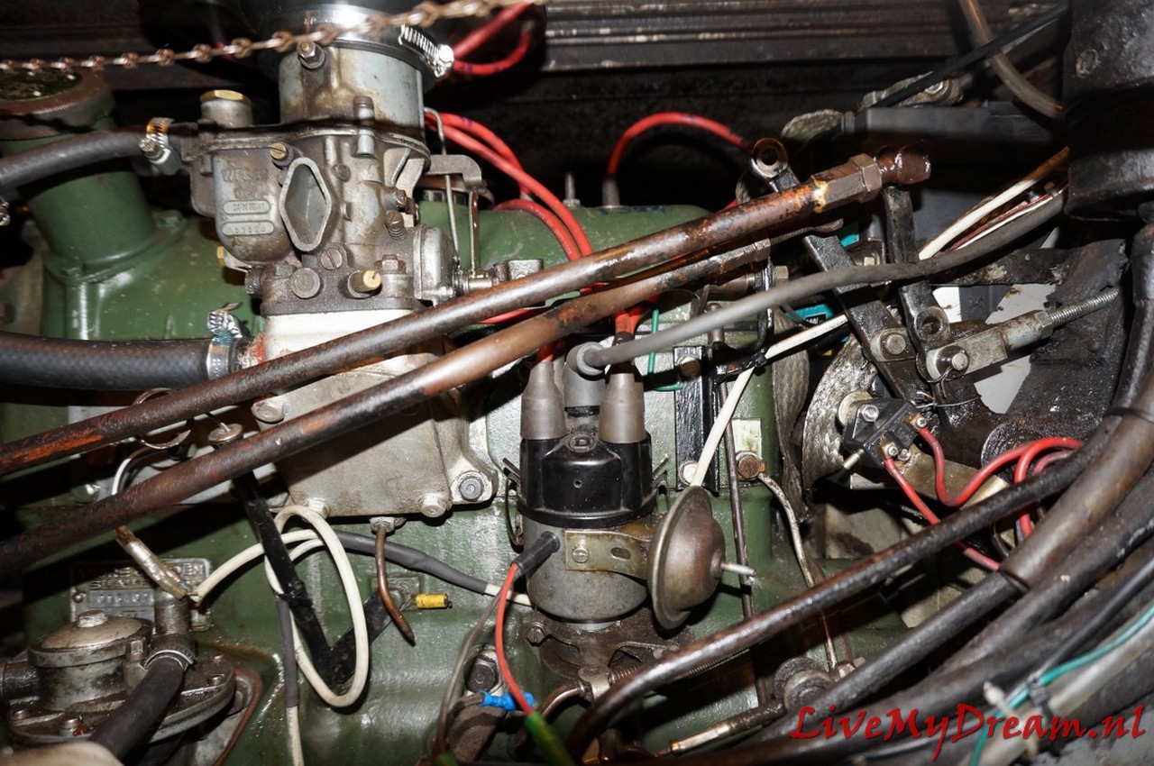
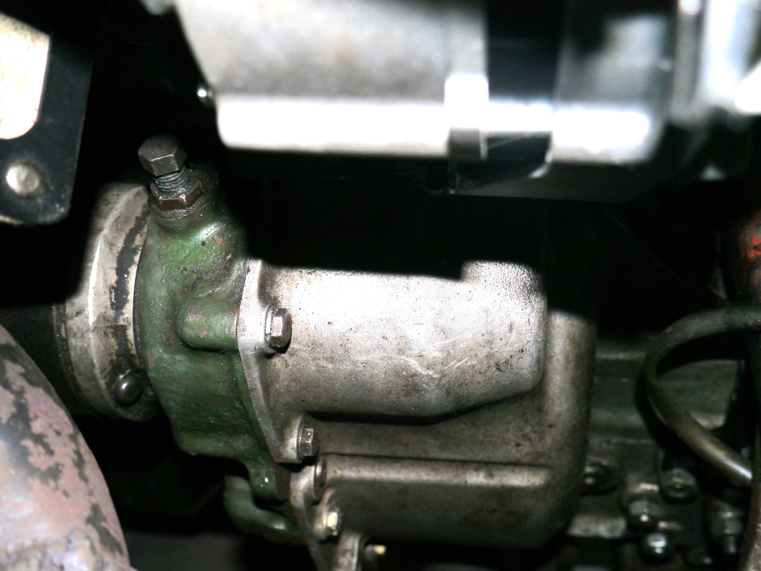
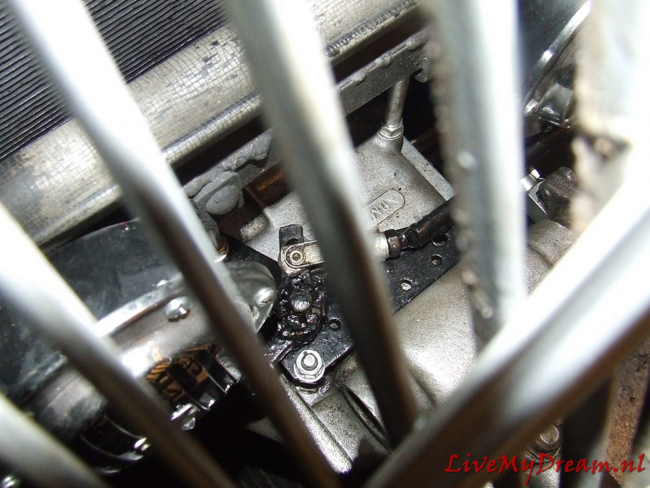
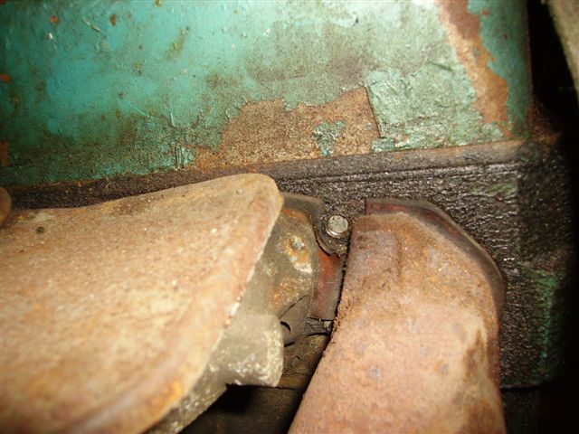
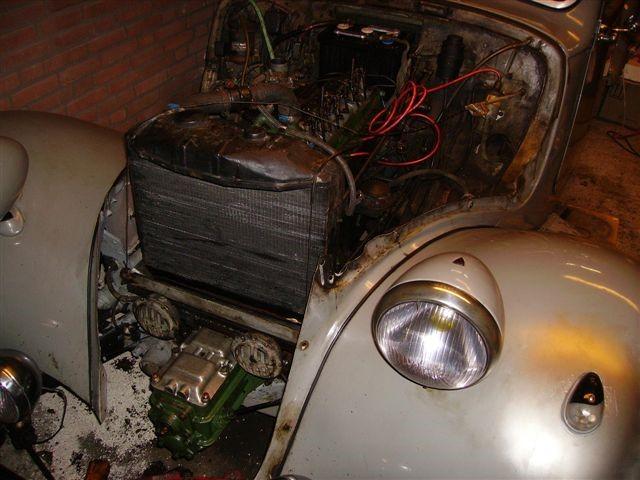
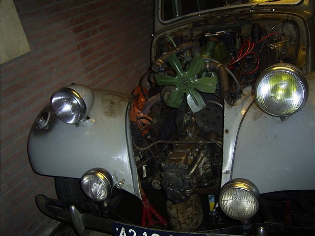
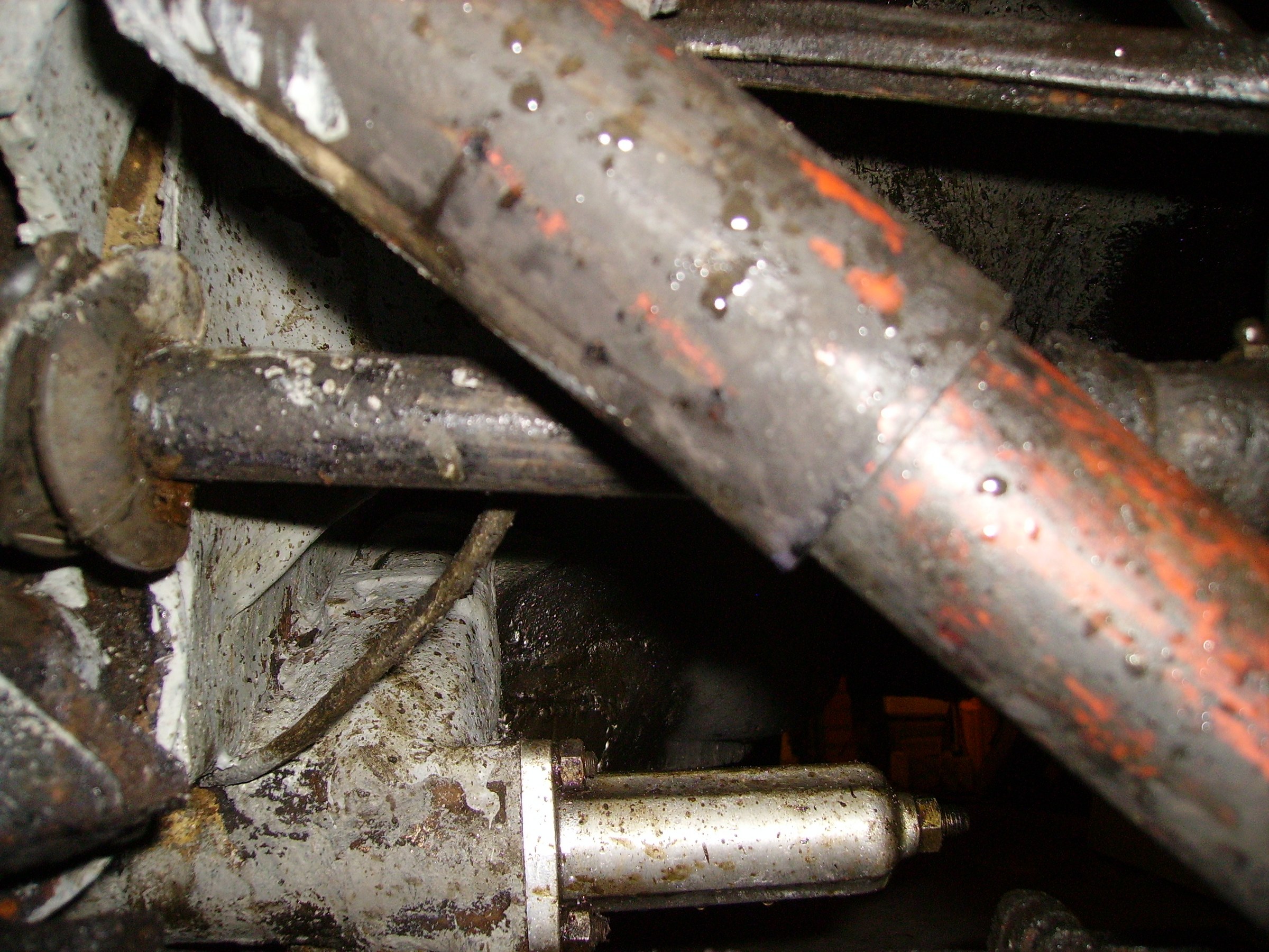
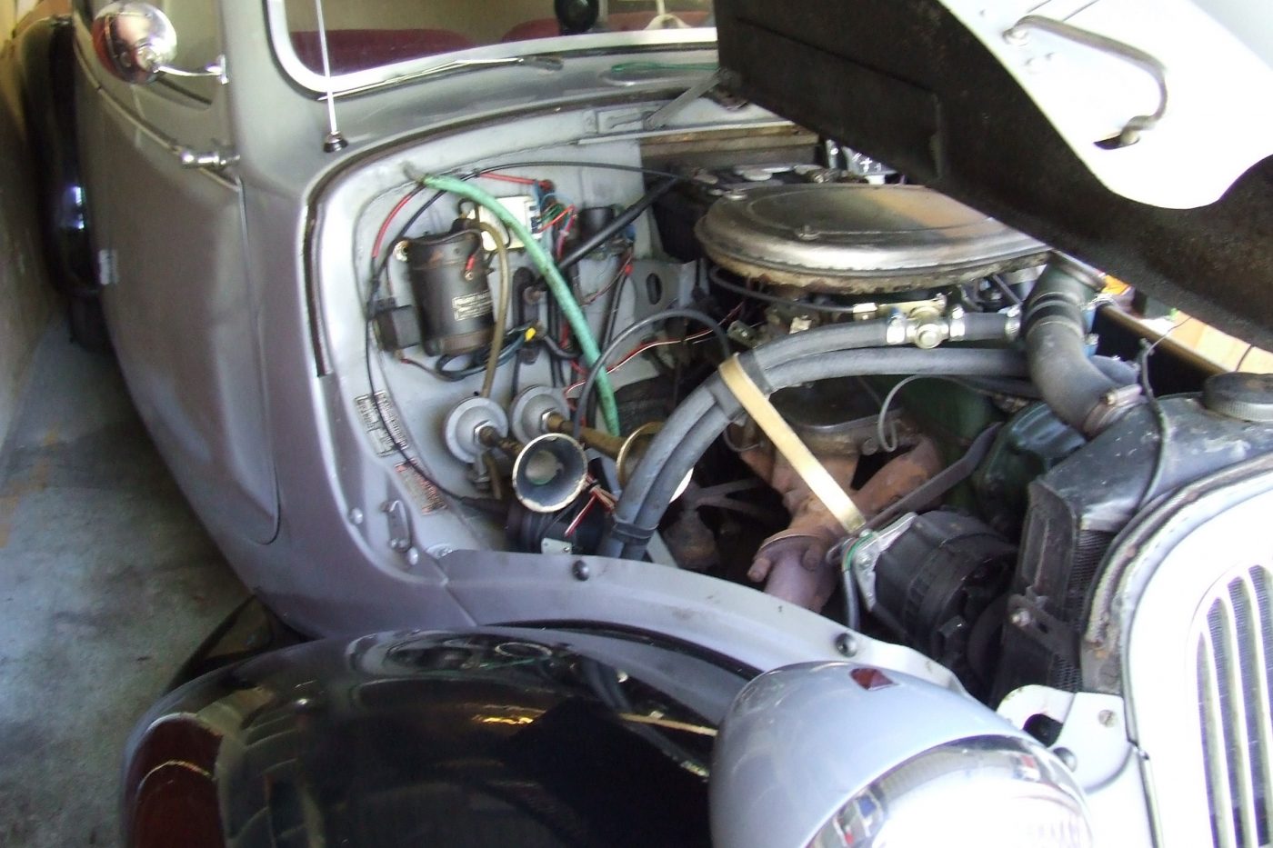
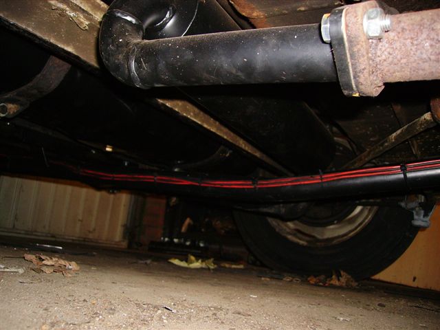
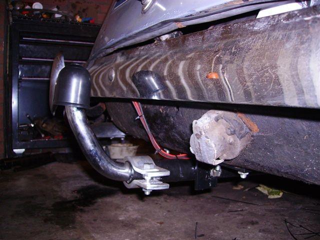
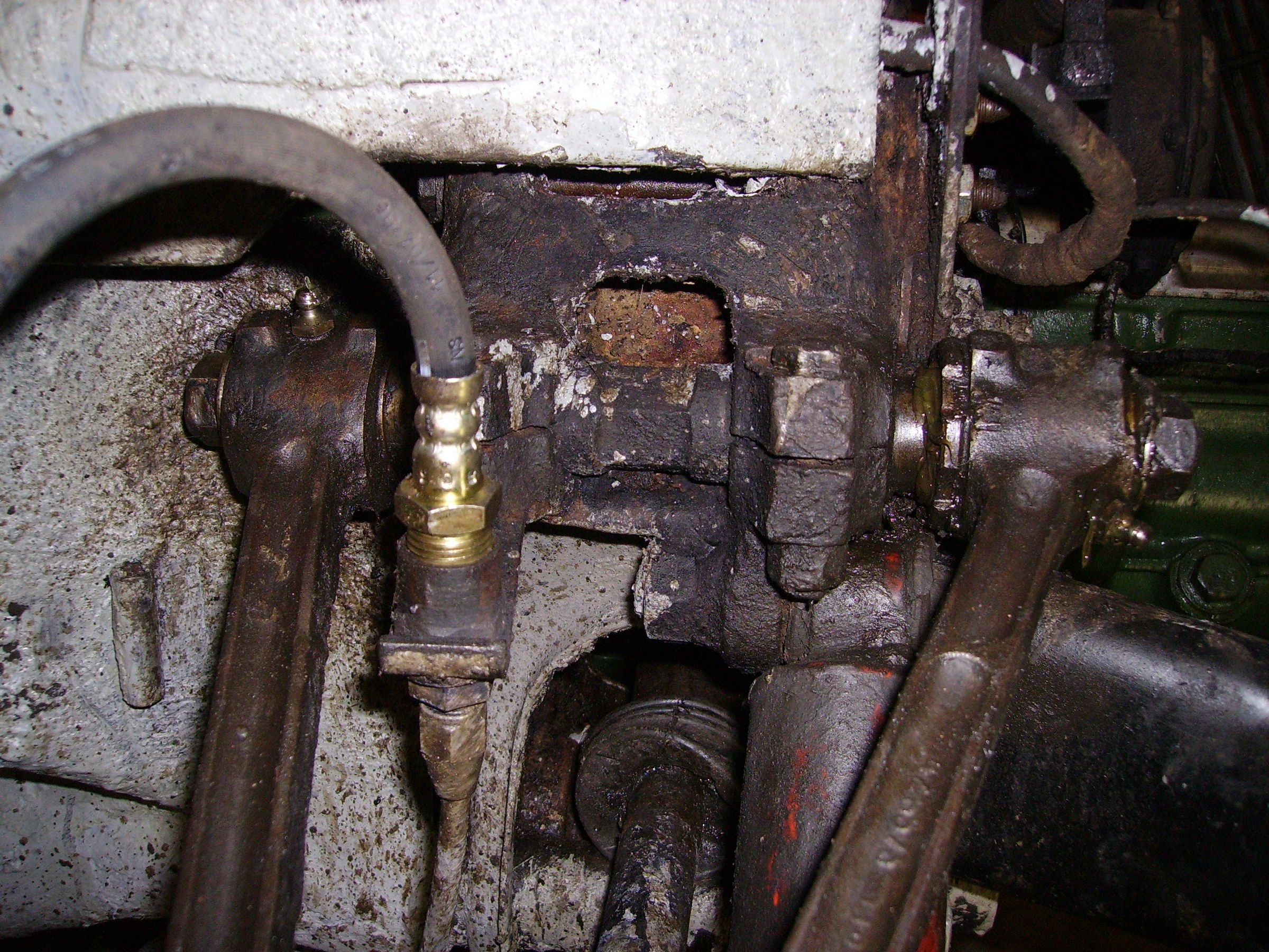
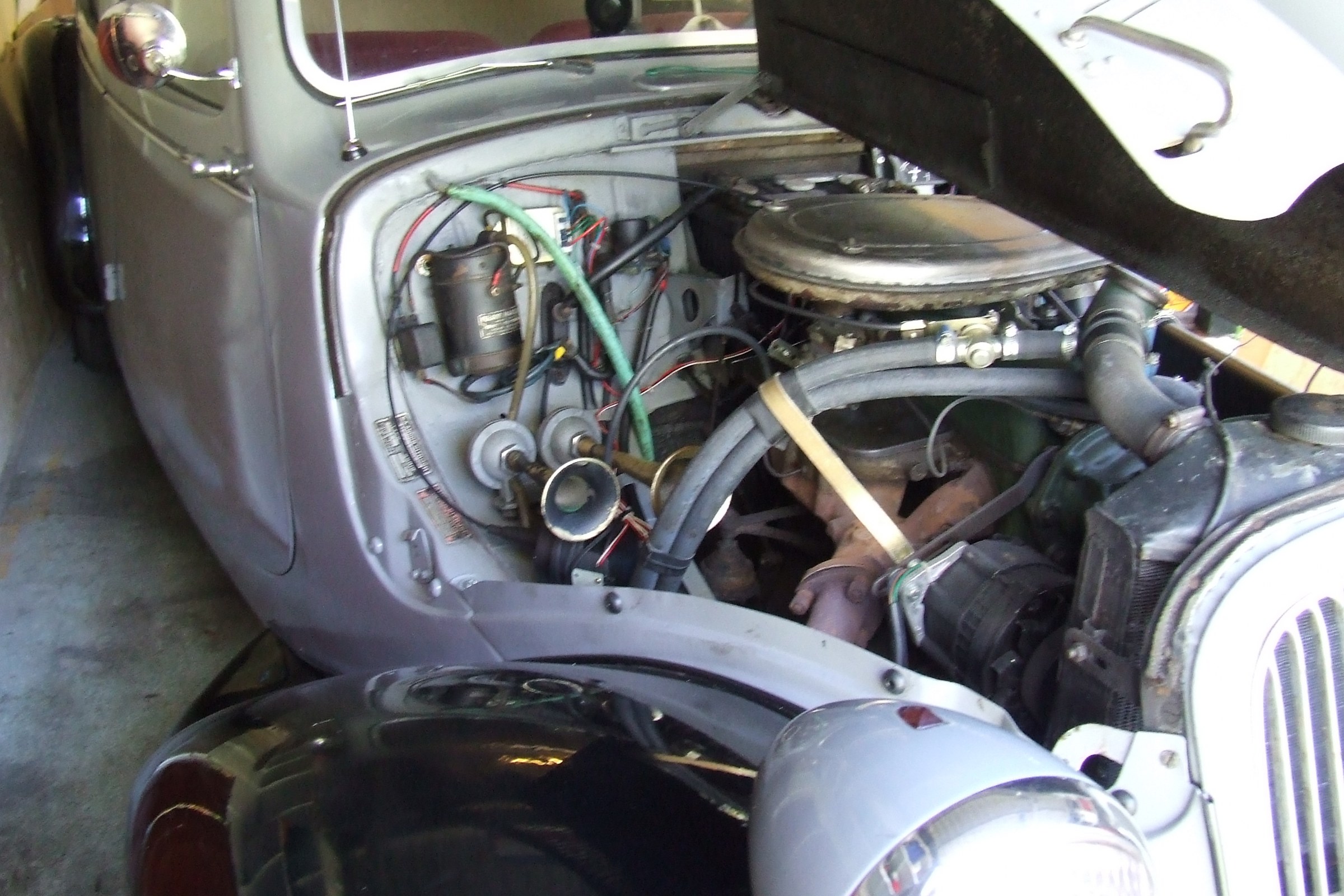
See photo below, The starter motor is under the exhaust manifold of this engine, in the same original location as on the Traction Avant 11D engine.
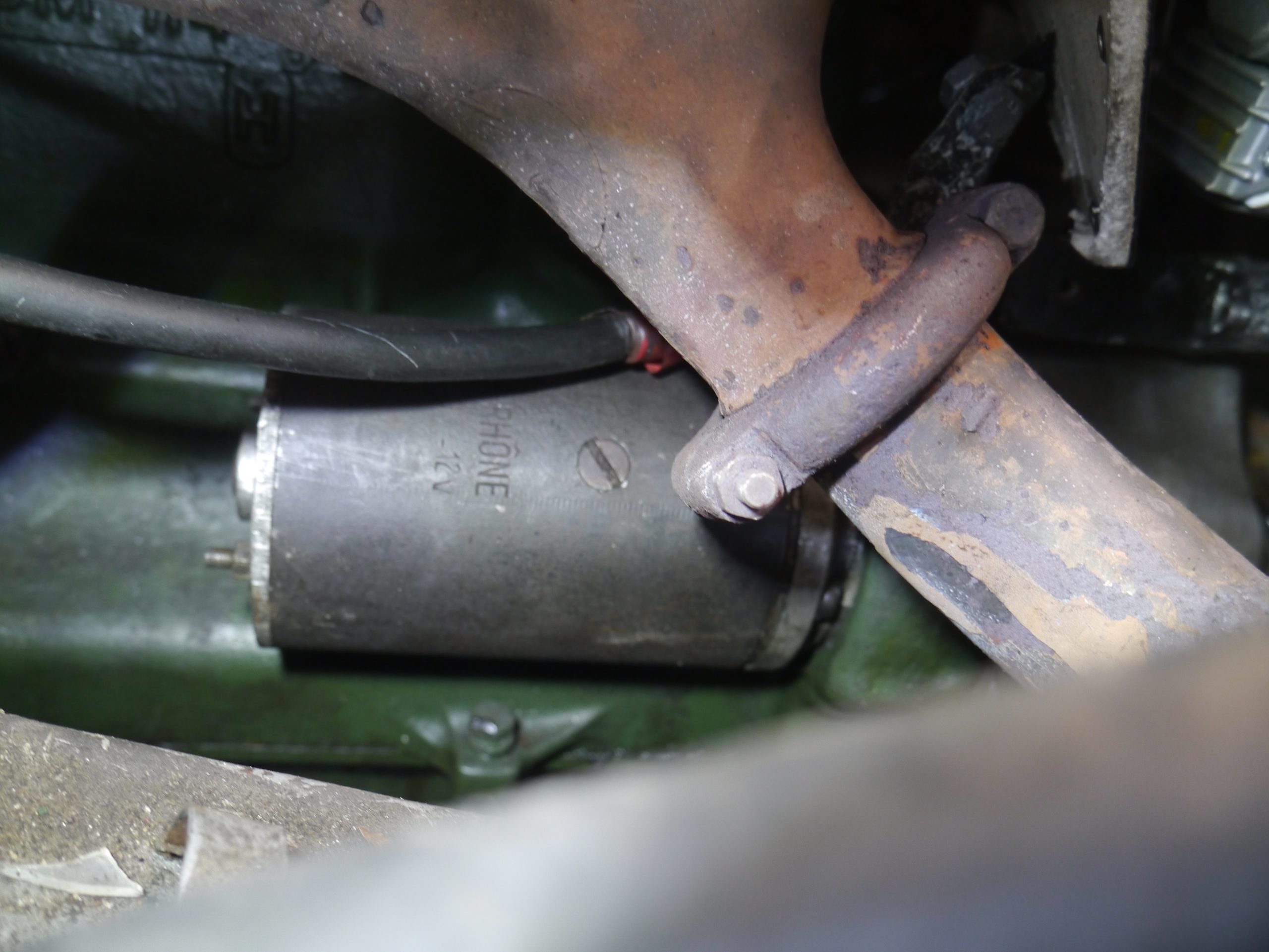
You can also remove the starter motor from underneath, but putting it back in is really easier from the top. Unless you have a bridge, of course.
As a possible emergency measure I mounted the original Traction Avant 6Volt starter motor, but it does not engage the Citroën ID flywheel. So quickly removed again.
The repair:
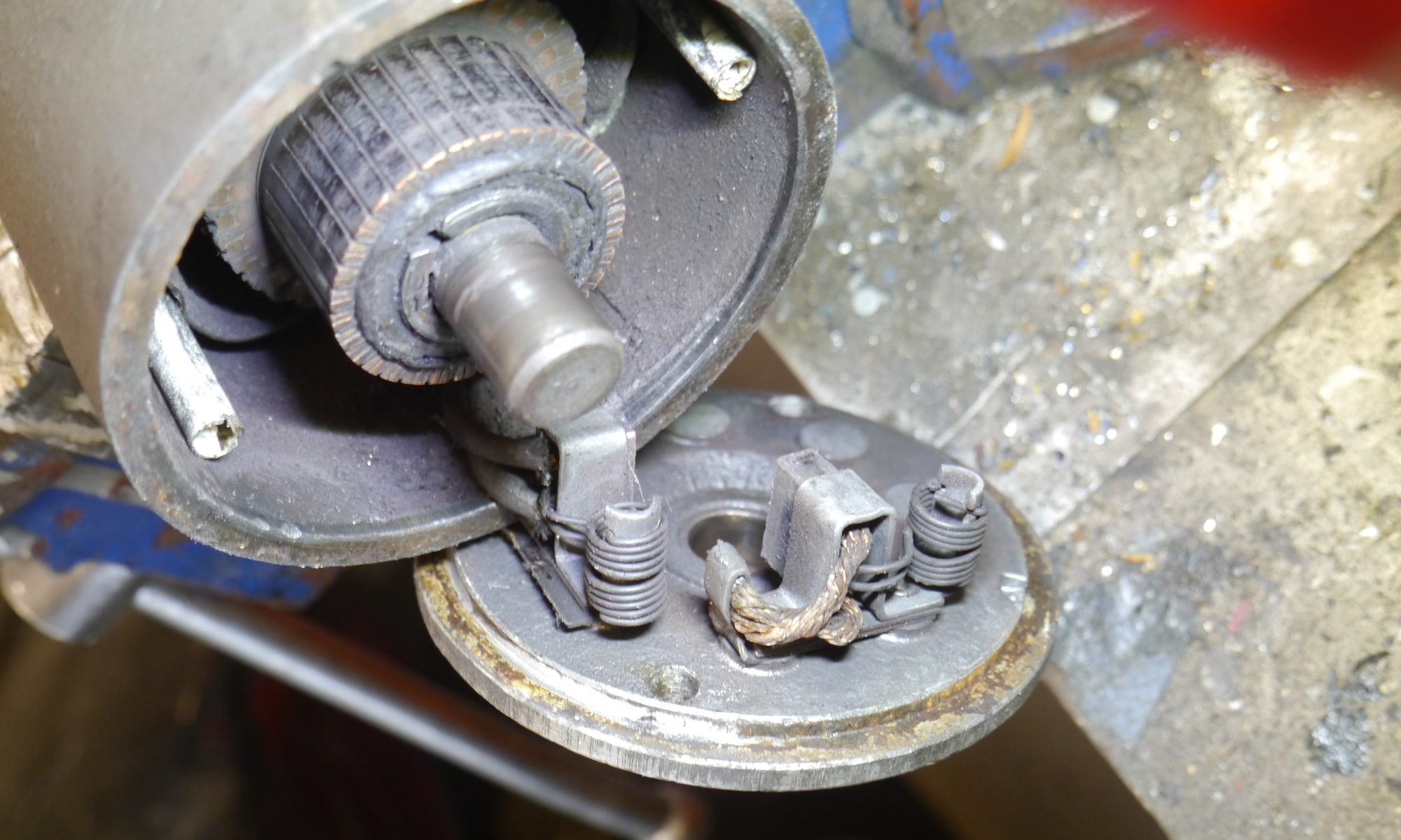
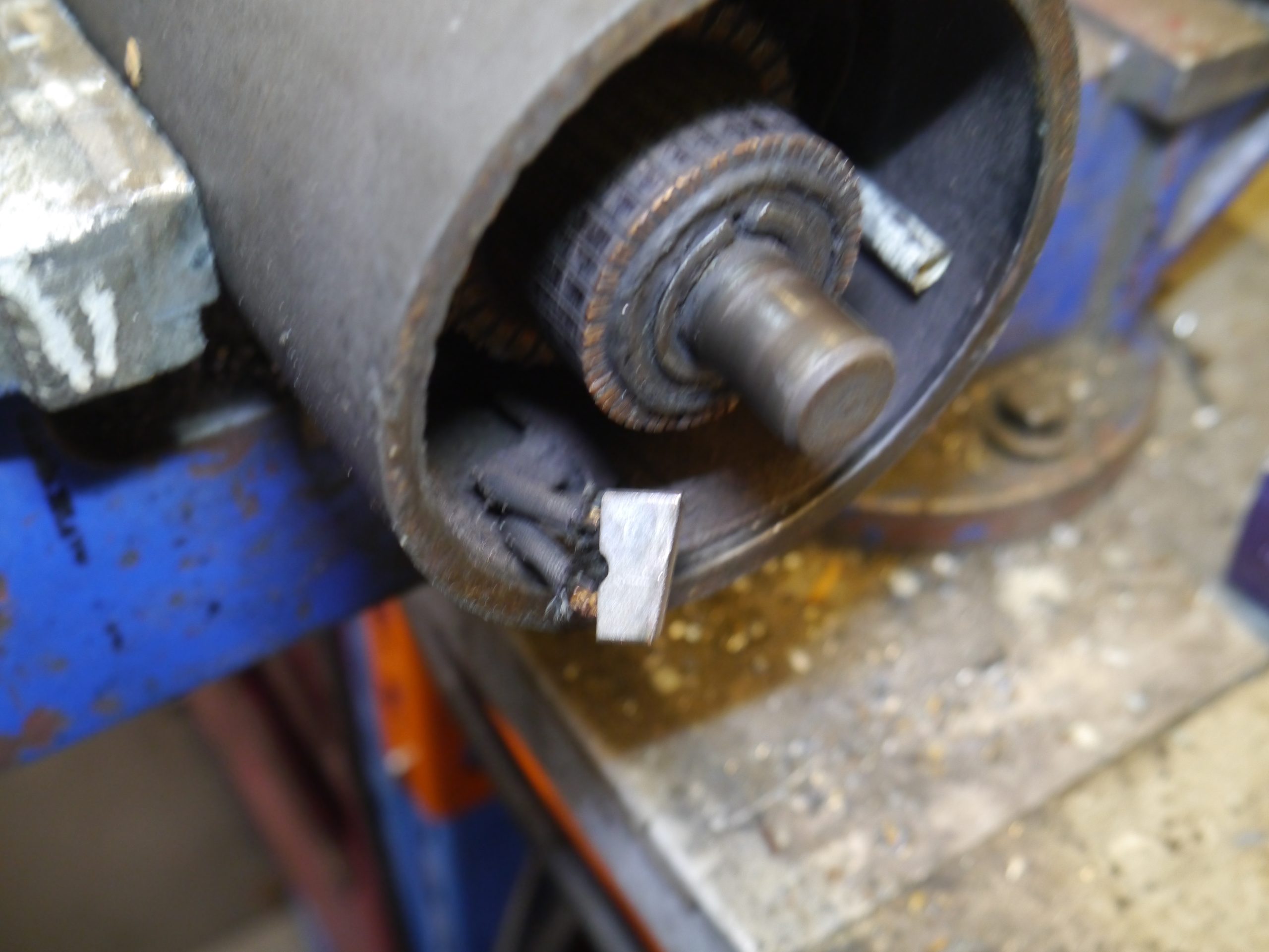
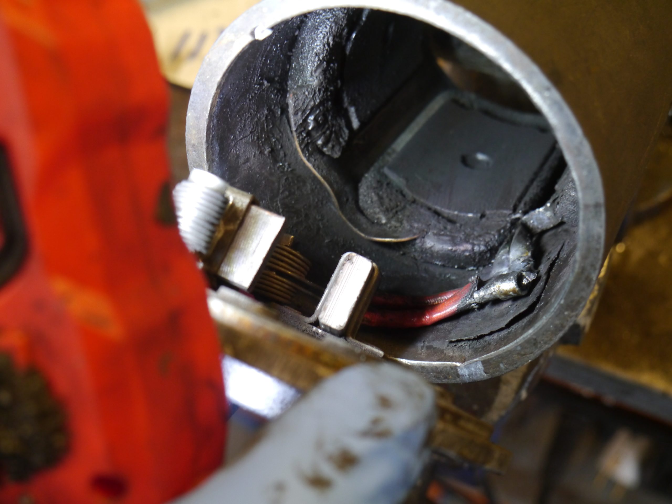
When you remove the two M6 nuts and locking plates on the back of the 12 Volt Paris-Rhone starter motor, you then slide the aluminum back including both carbon brush holders off a bit.
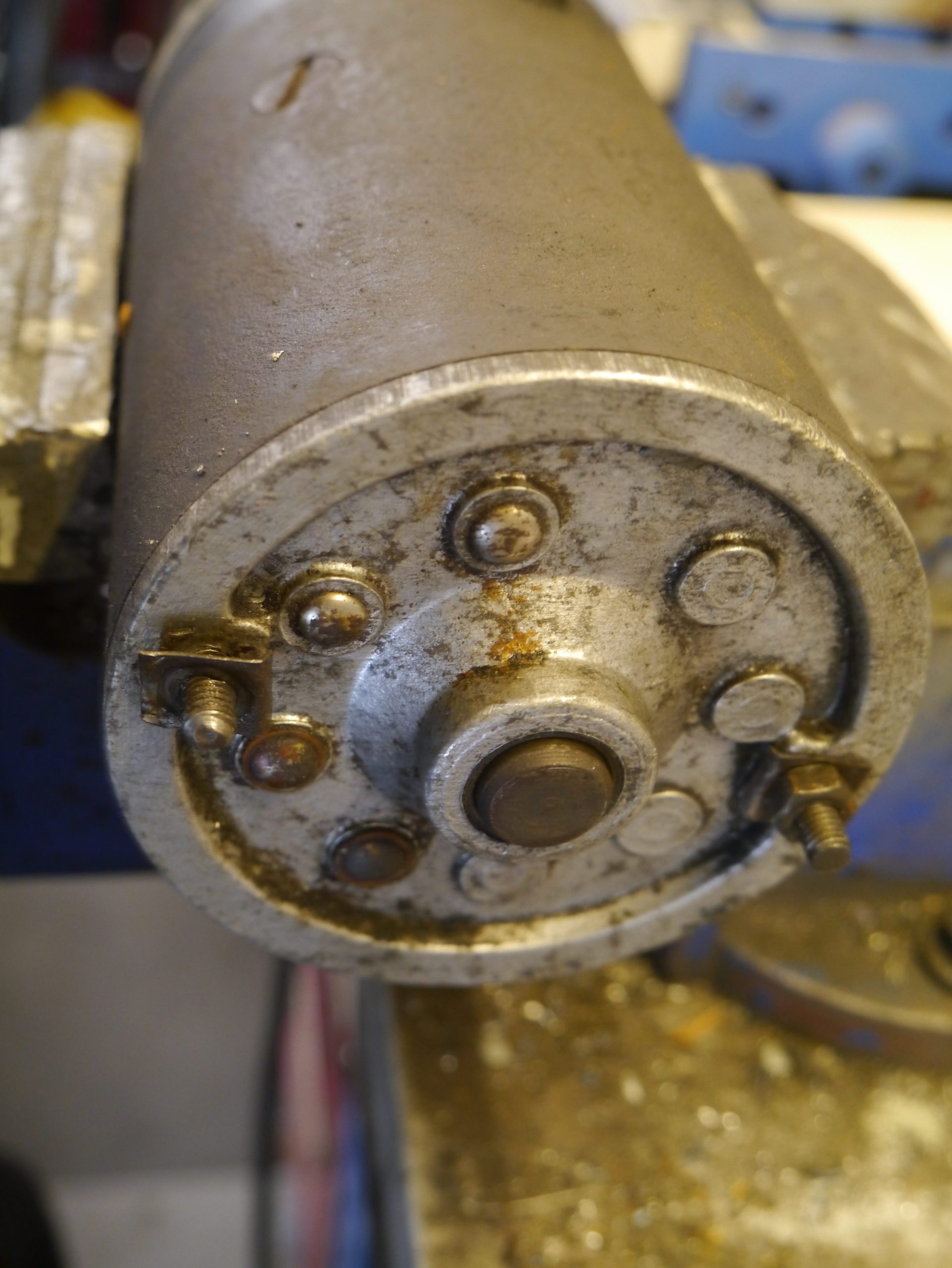
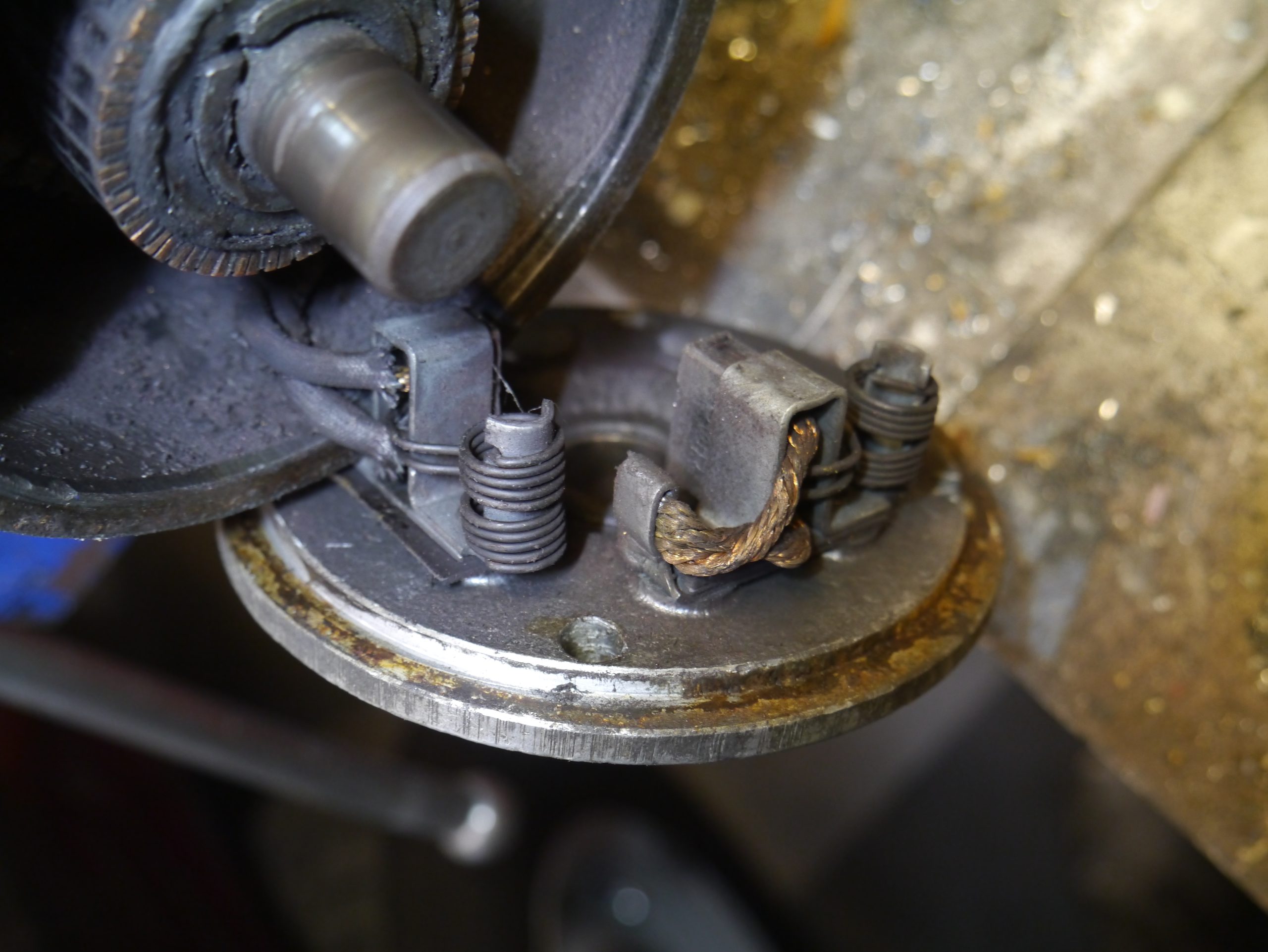
The carbon brush on the armature side (+) was the culprit, it was worn down pretty crookedly. It seems that one of the connecting wires had just a little too little space to allow the brush to move straight.
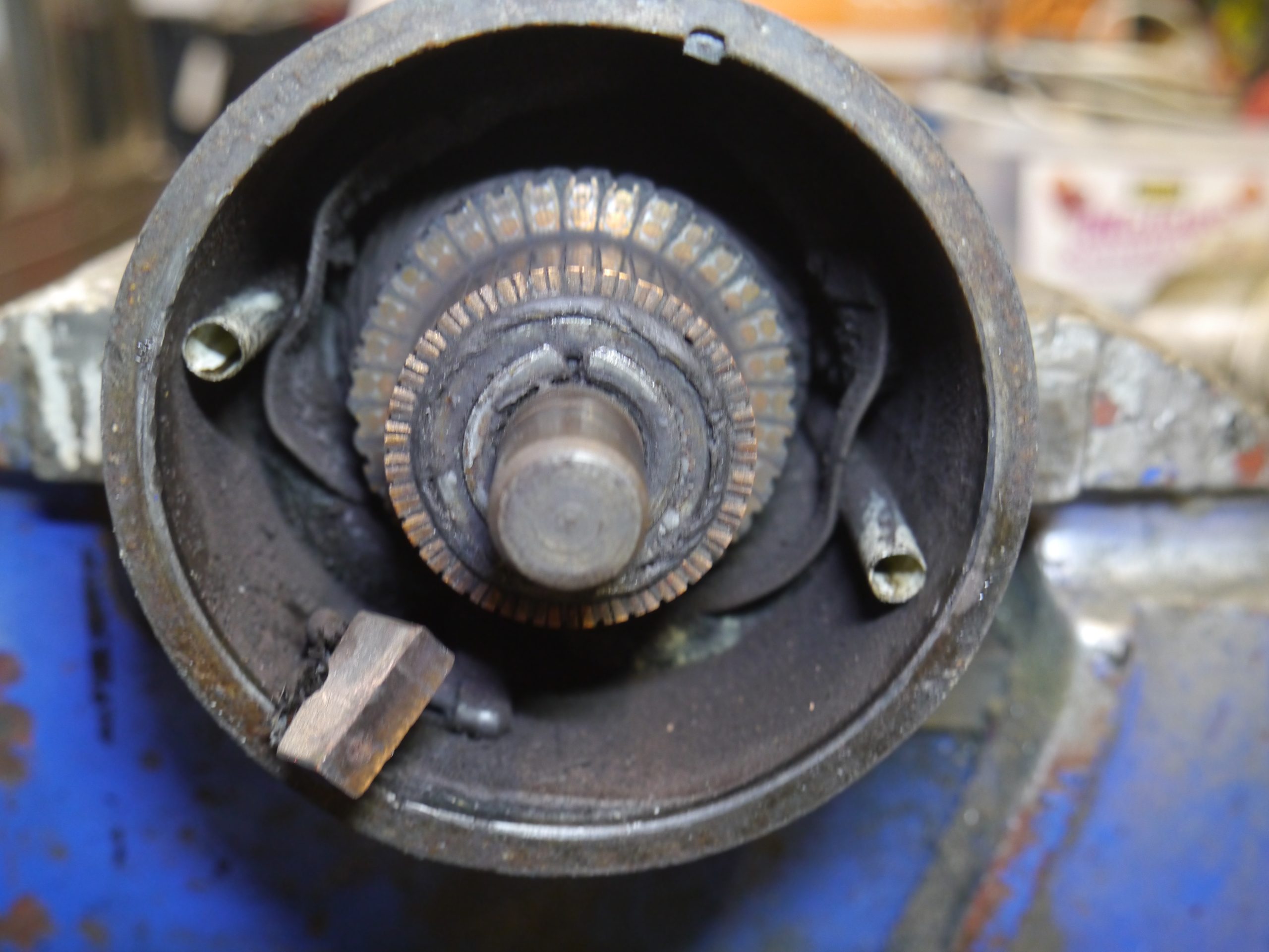
I then measured and ordered the carbon brushes.
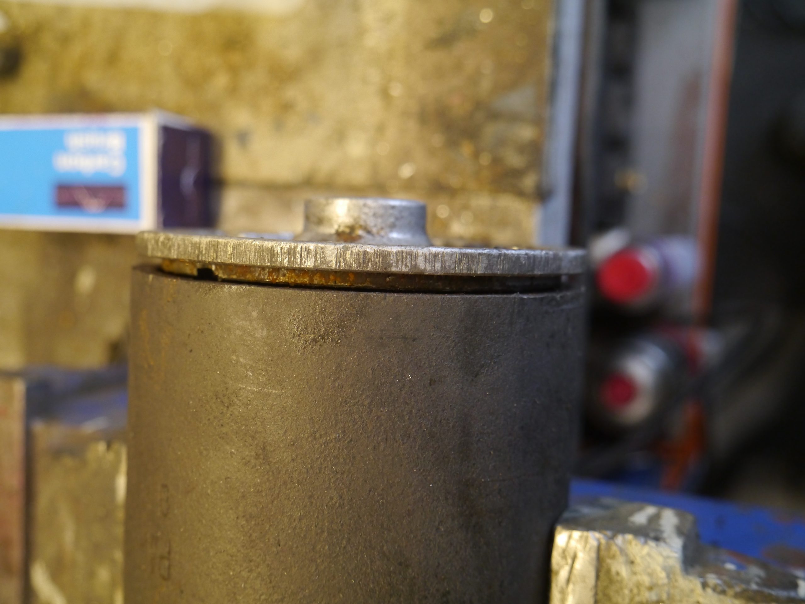
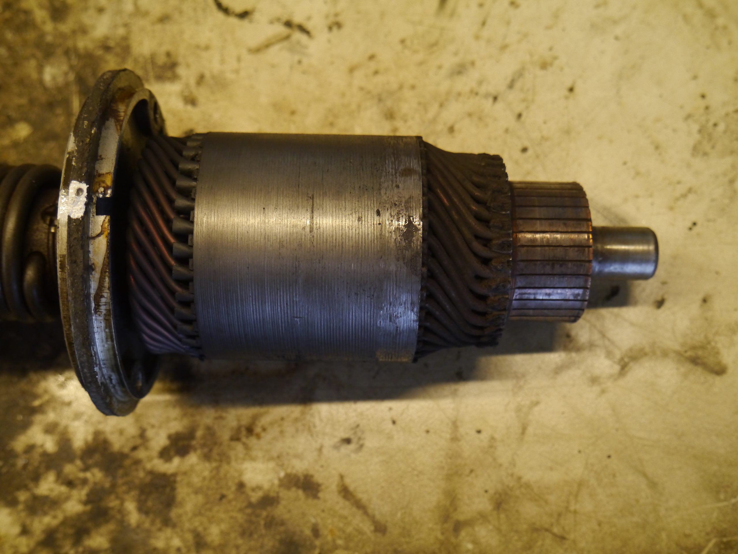
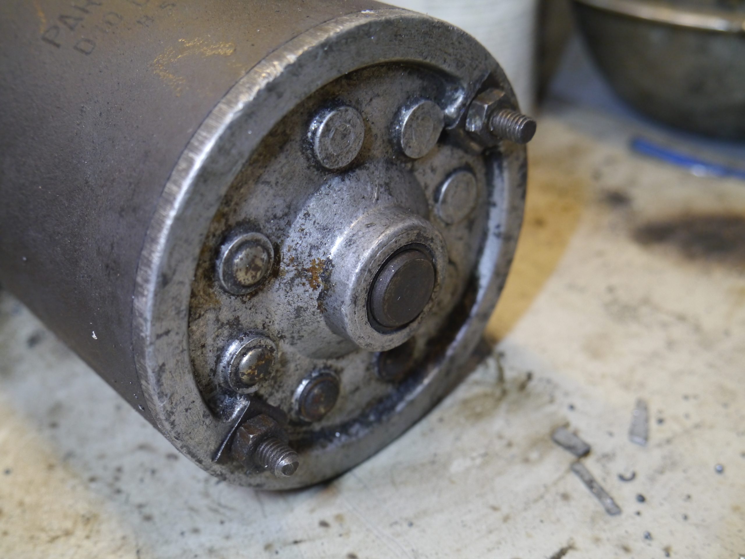
The starter motor is otherwise in fine condition, the rotor and collector also look good.
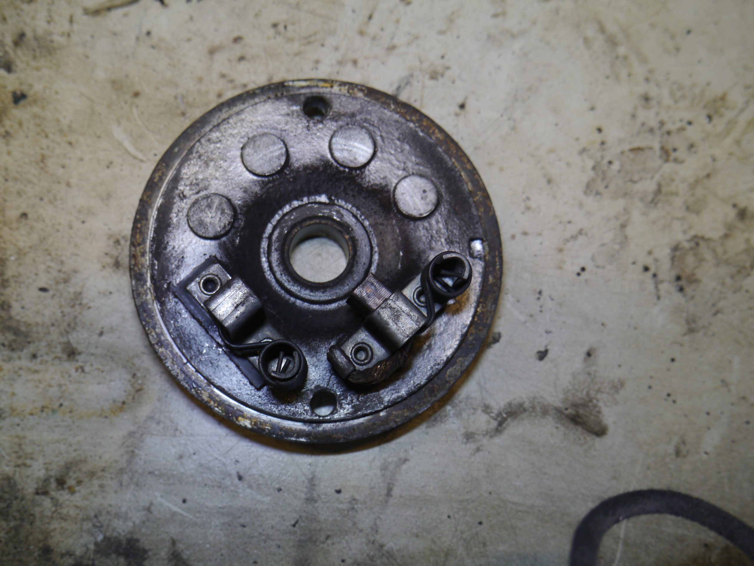
The carbon brushes are the same size (about 7×17.8 mm) , and they have the same kind of soldered wire connections.
In the end it was only necessary to replace the carbon brush on the armature side, the other carbon brush which is on the minus is barely worn.
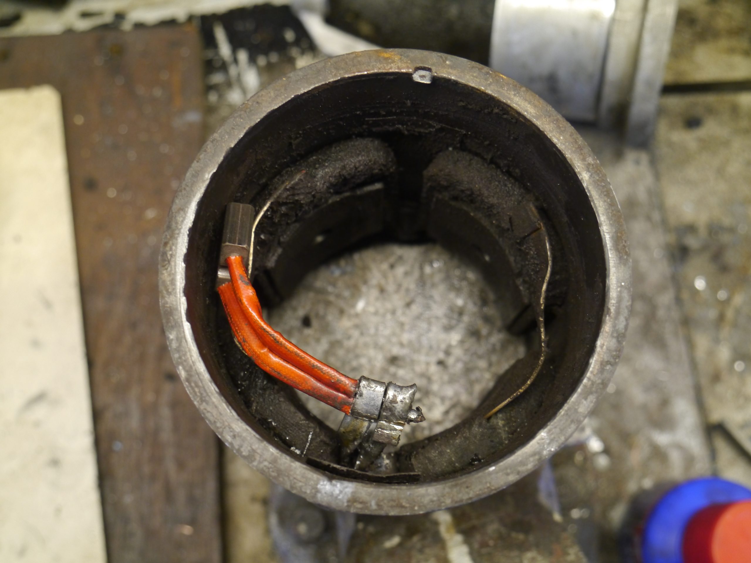
Above with the pre-soldered wires already mounted, and below AFTER soldering, after mounting the carbon brush in the carbon brush holder.
The collector of the rotor was completely flat so having it reworked in my lathe didn’t seem to make sense.
After cleaning and assembling it, I first tested everything using a small battery from my motor bike, gave everything a little grease, secured the back with the 2 locking plates and reinstalled the starter motor in the TA.
Immediately started and everything OK again!
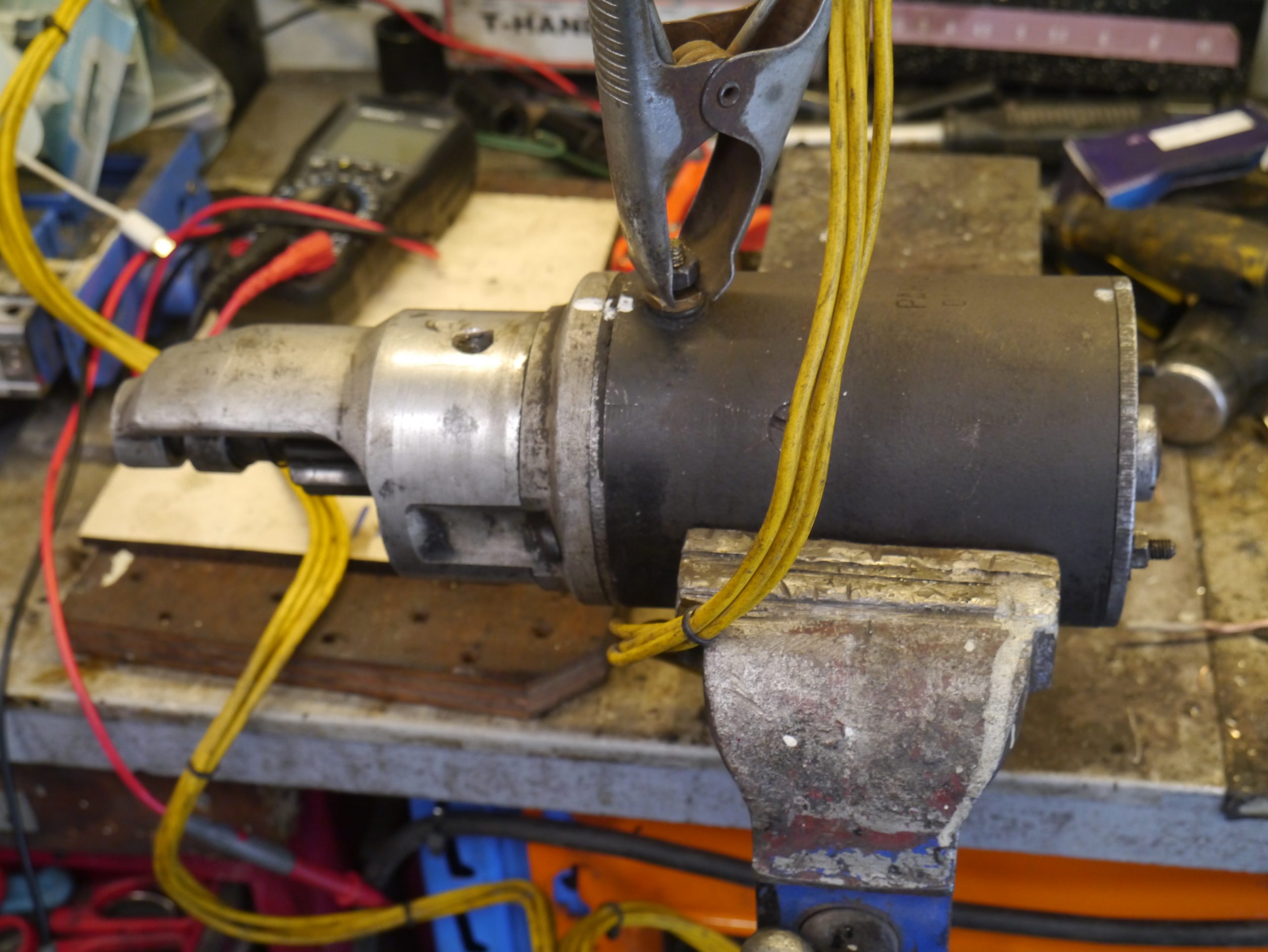

Above you can see the rough end result with which I have now (2022) already been able to travel a few thousand kilometers.
In the end it has been a valuable project.
Driving the TA is perfect, shifting up and down is smooth and the car behaves very well.
An important advantage of the new gearbox is that the engine makes far fewer revolutions when driving at cruising speed.
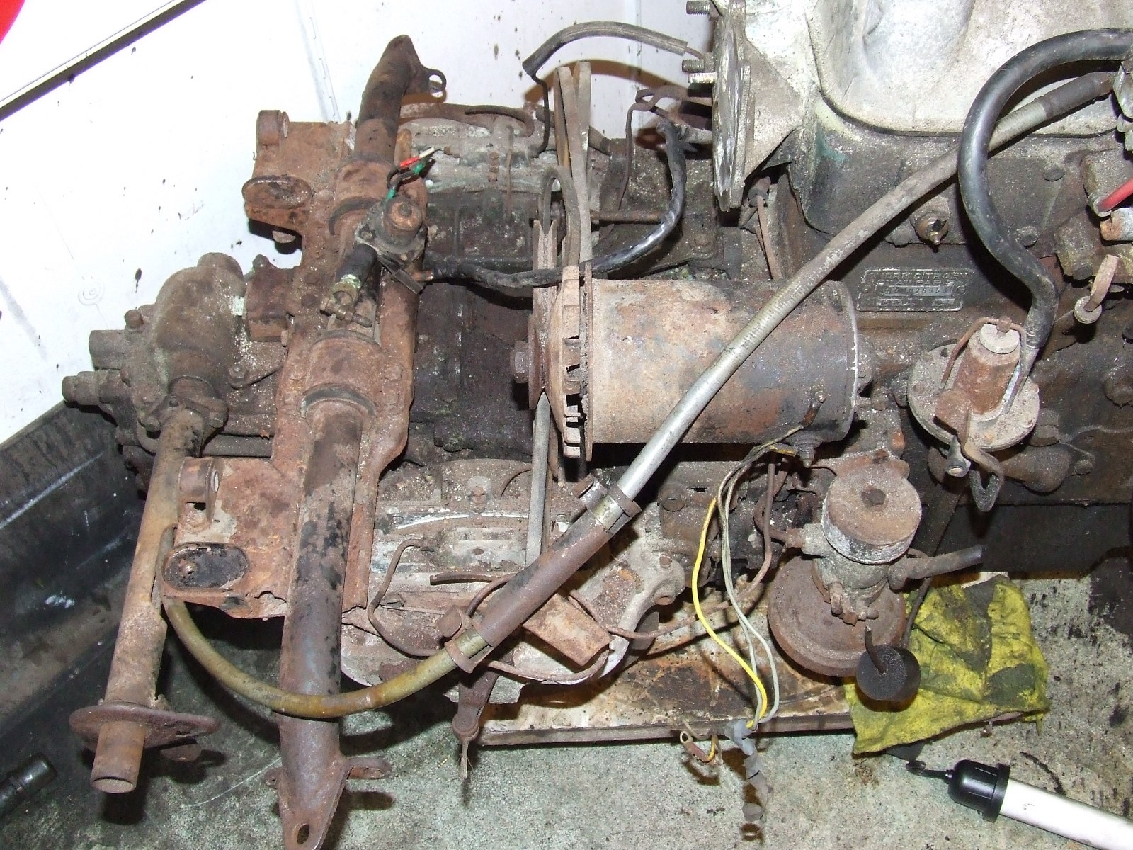
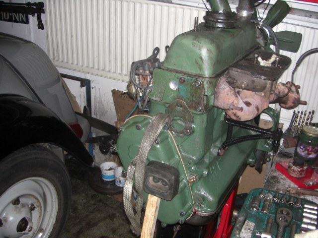
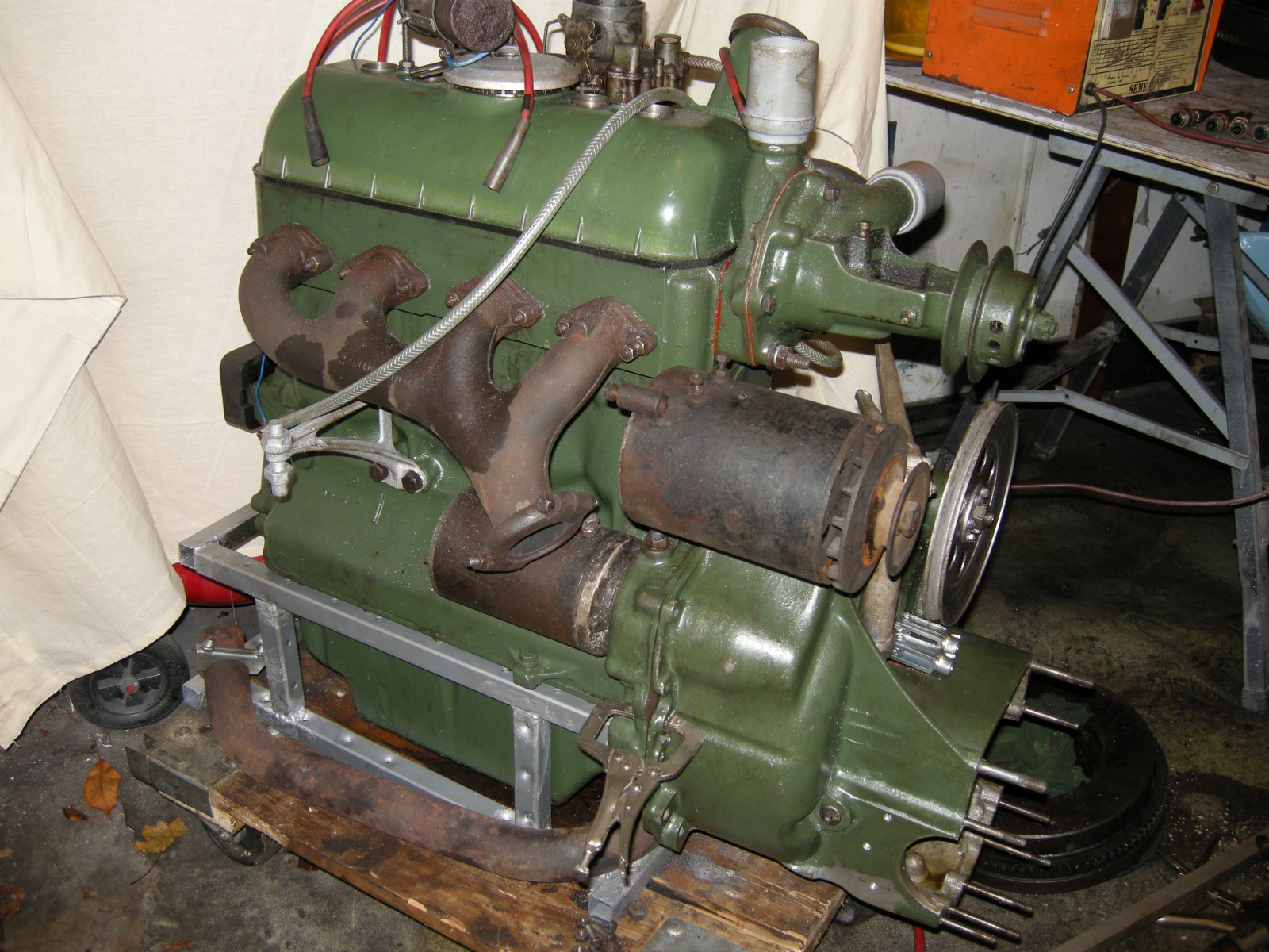
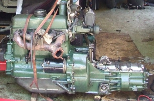
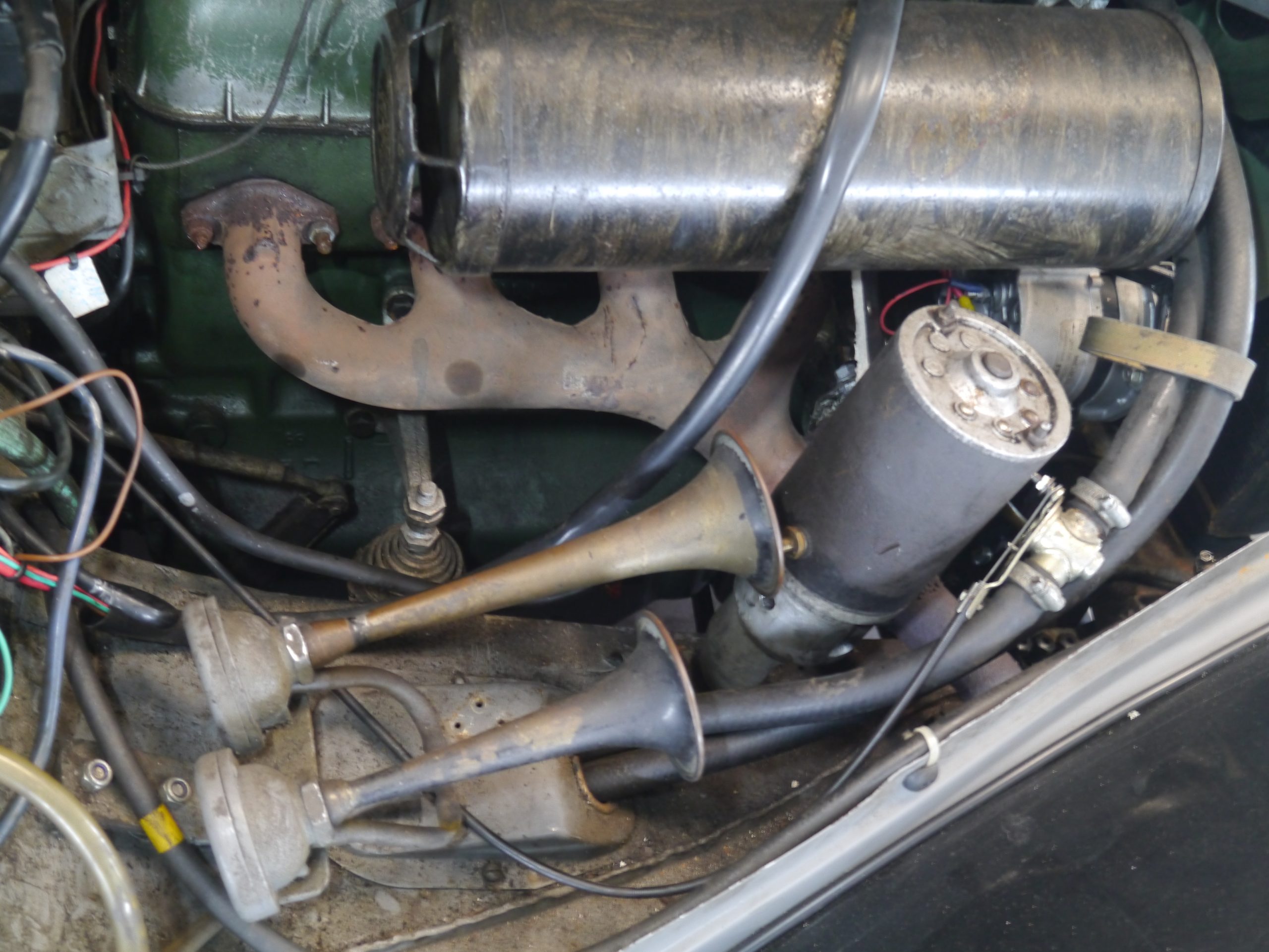
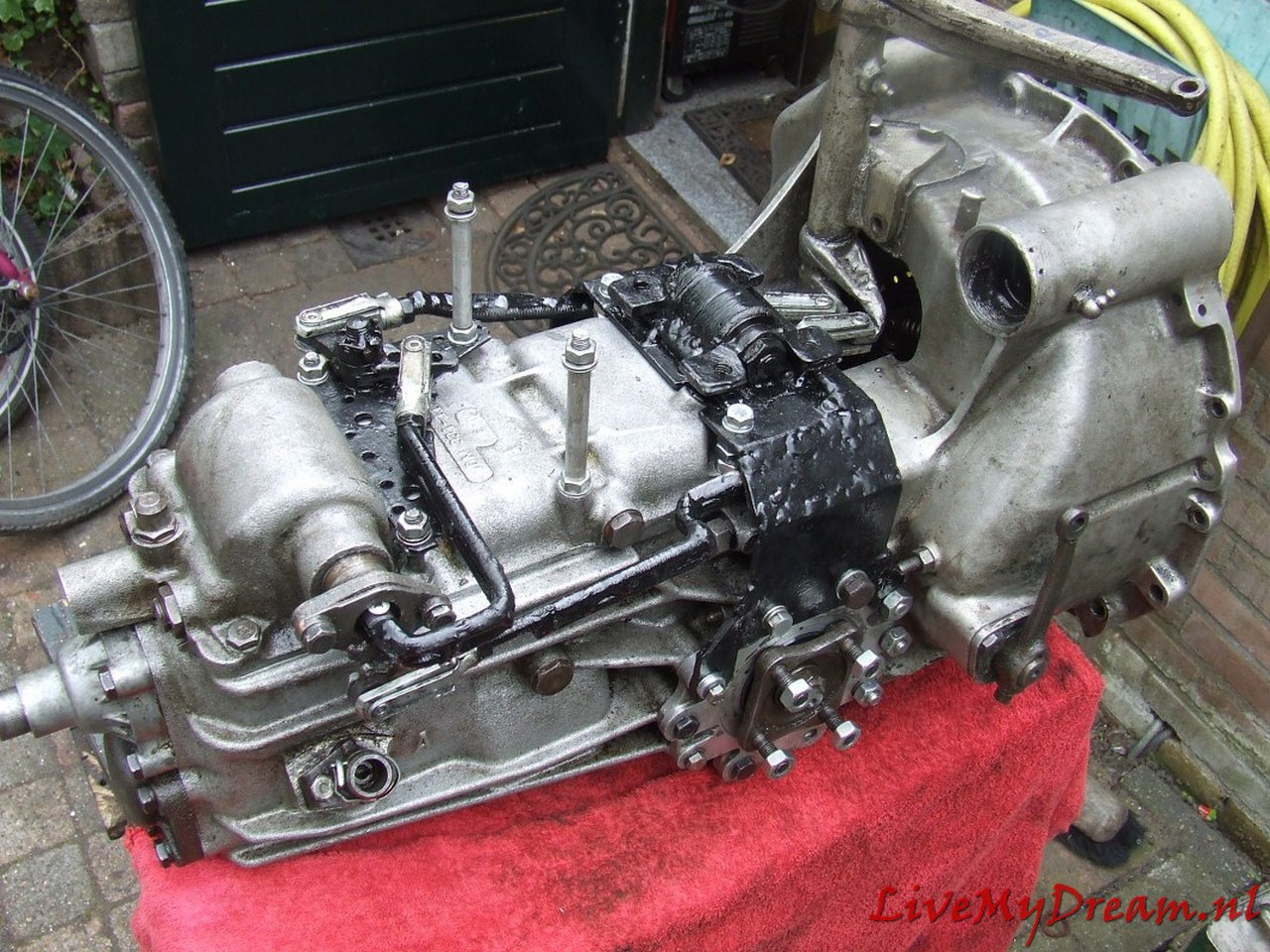
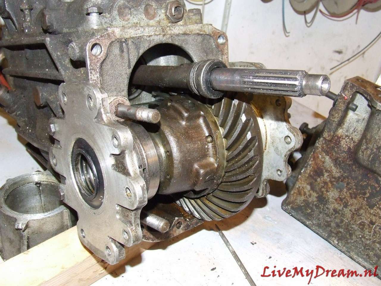
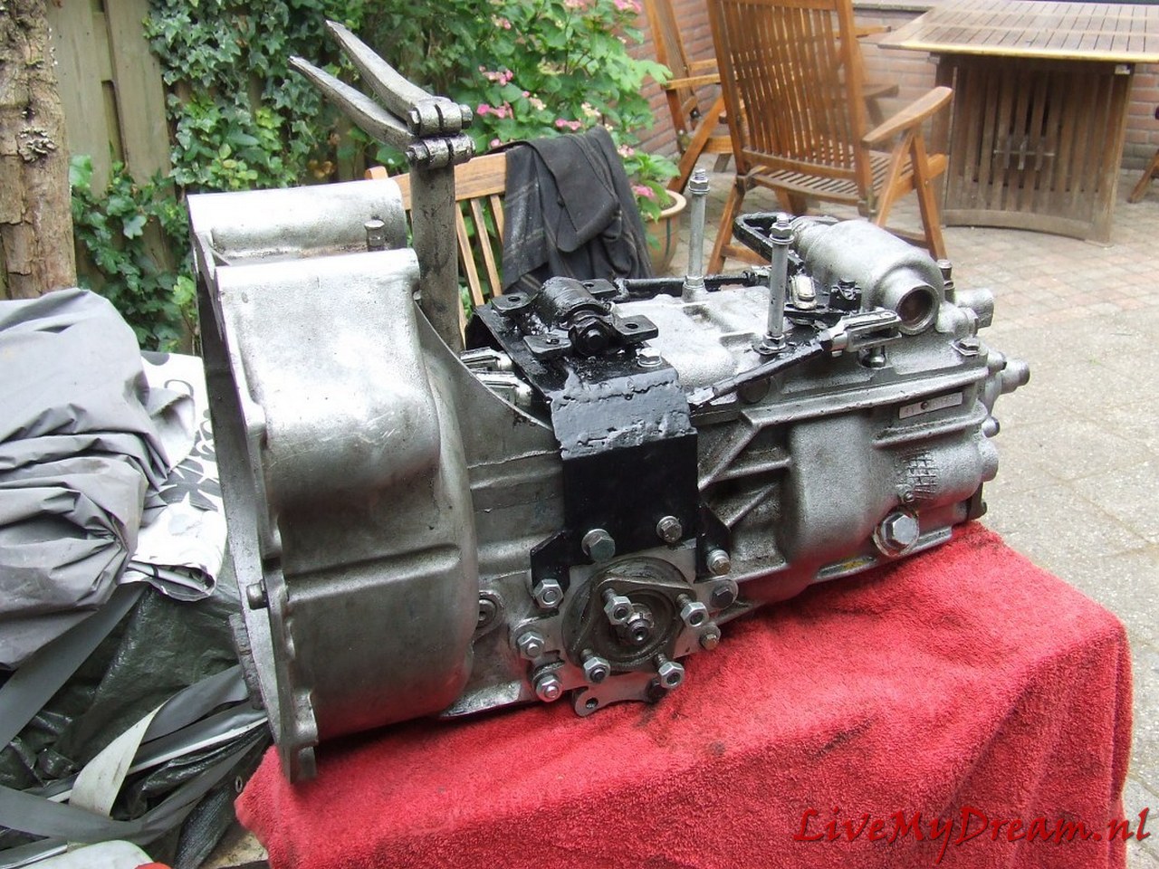
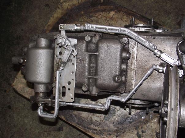
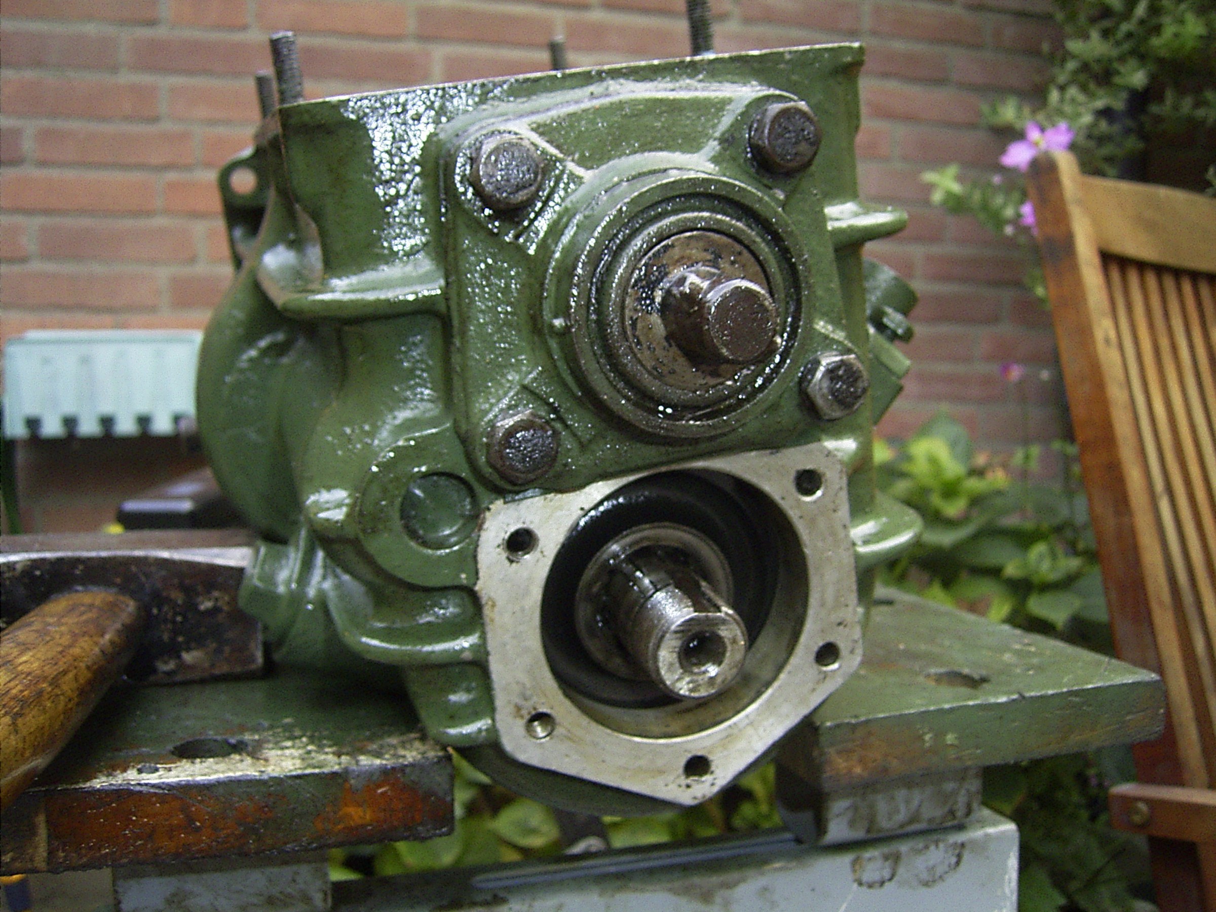
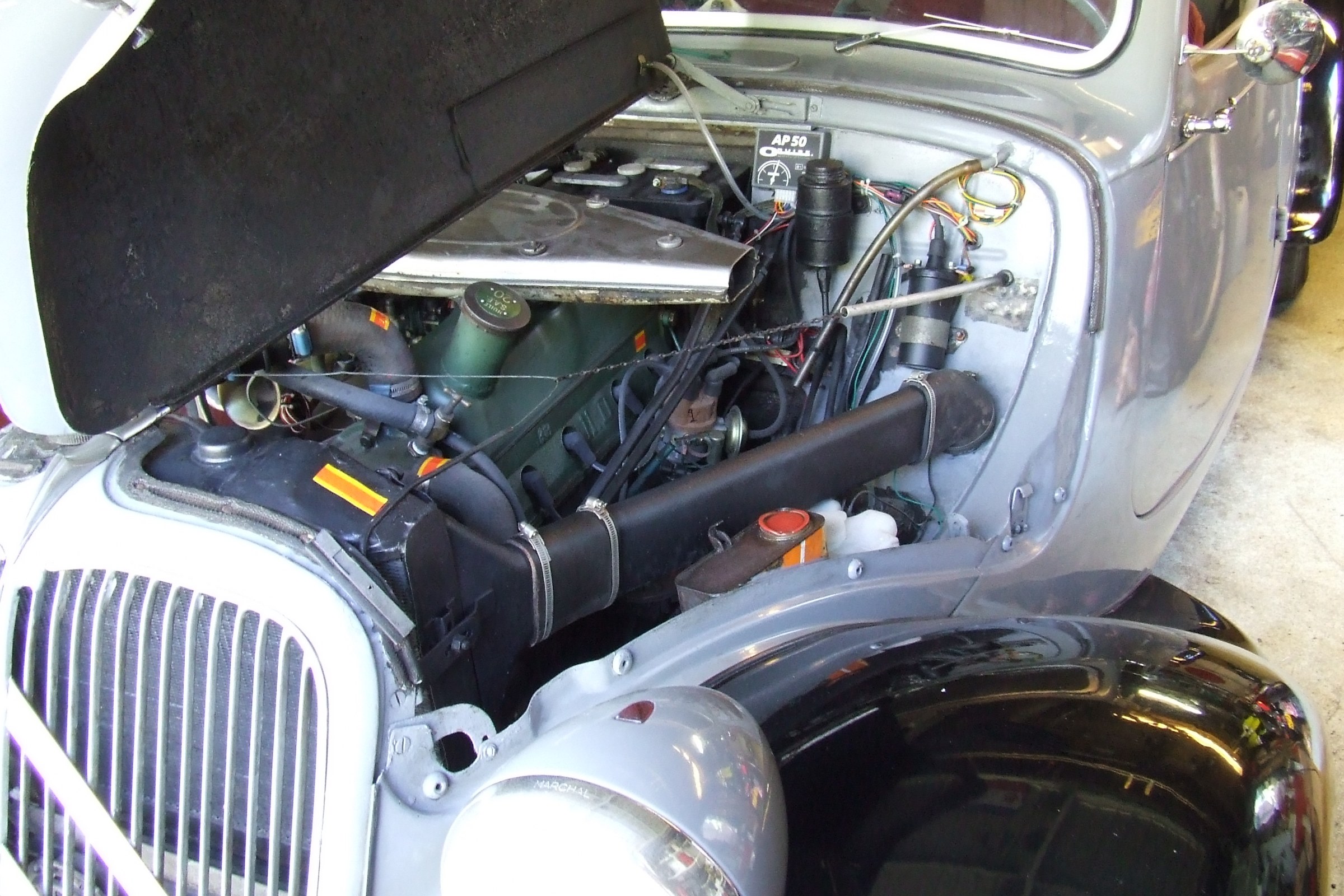
Above you see the overview of the donor long-stroke ID19 engine with the 4-speed gearbox.
At the time of purchase everything was still attached: brakes, suspension, shift sleeve, HD regulator, fuel pump, alternator and so on!
The water pump had already been removed by someone else.
The donor car had serious side damage and was declared total loss.
It was a pity but I was lucky with it.
The approach
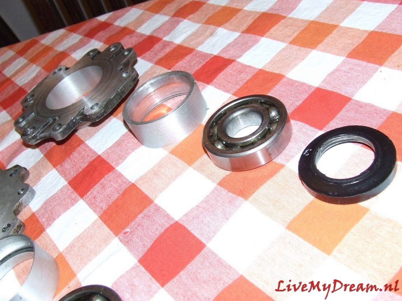
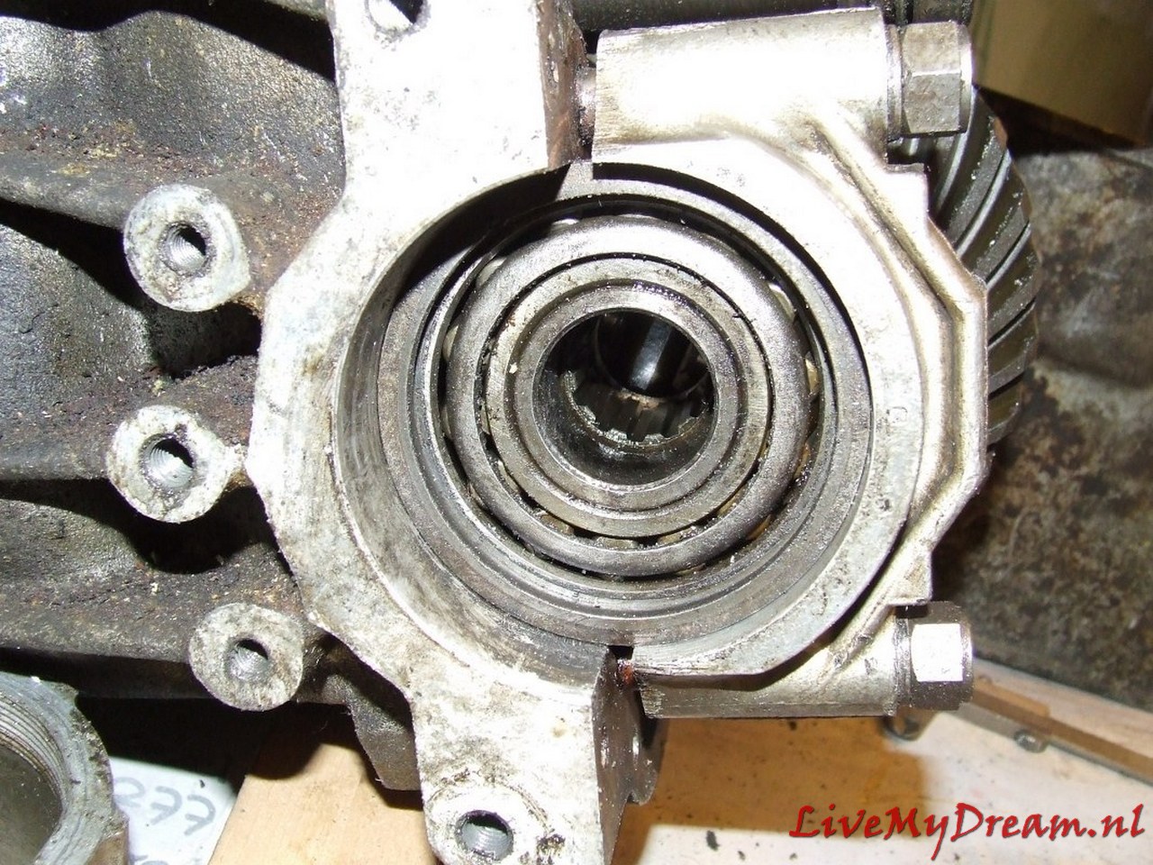
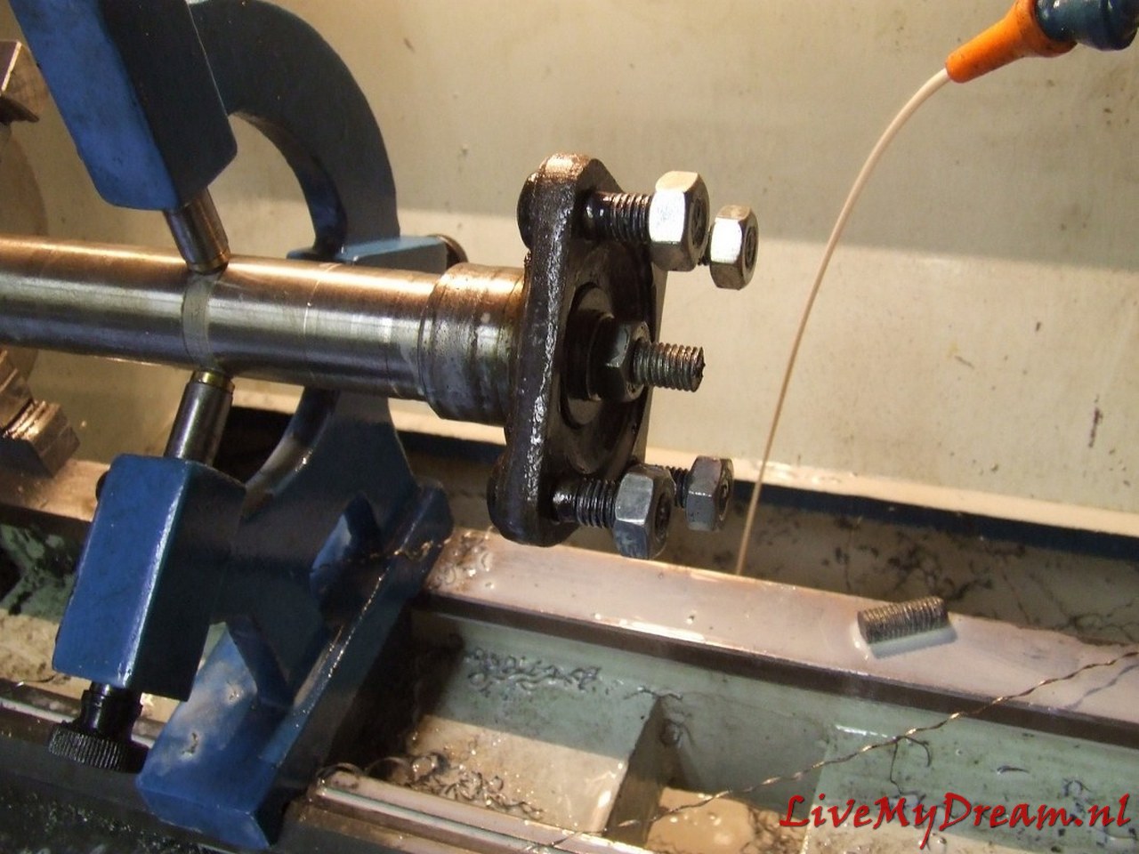
The long flanges of the 4-speed gearbox have to be turned off on the lathe. From the ends of the flanges (gearbox side), bushings are turned which will sit in the turned off flanges.
This is necessary because the bearings and seals are not available in outside sizes that will fit into the inside of the shortened flanges without fail.
New bearings and new oil seals will be enclosed in the bushings in the turned-down flanges.
The shaft chucks will be turned down by about 1mm to a commercially available inner size for a bearing and seal. (35mm axle thickness)
The flanges are turned out by 3mm to allow the axle jaws to mount properly on the TA internal body shafts.
A stainless steel bushing is turned to allow the outgoing internal TA shaft to rotate tightly in the ID crown gear.
In other conversions, this bushing is usually not installed, but the lateral pressure on the end of this shaft without a fitting bushing becomes, in my opinion, too great to be able to drive it very long without wear.
The bushing has an oil groove on the rotating inner side.
This bushing is needed on 1 side of the donor ID crown wheel and is tightly crimped into the crown wheel.
The ID shaft rotates tightly in the ID crown wheel and is slightly thicker than the TA shaft.
The difference in thickness is corrected by the stainless steel fitting bushing.
The satellite wheels, internal bucket axles and differential housing of the TA are reused.
The satellite wheel (which of course fits the pignon gear of the ID box) comes from the donor ID box. Of course, after the conversion you have to determine the preload on the Timken bearings again and make new spacer rings to fit the whole with the correct preload in the ‘clock’ properly.
Measure the play of the crown wheel according to the workshop manual, and so on.
This solution is robust and will not break or wear excessively.
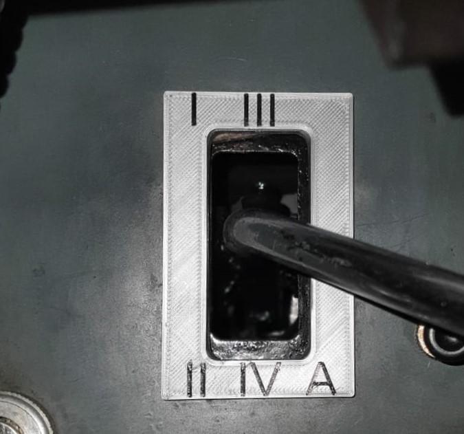
Controlling the gears was also an important issue for me, because the Traction Avant has a different standard gear change sequence and the known ‘conversions’ to 4-speed all have an extra button or lever to operate the reverse of the gearbox. I chose to convert everything so that a regular H-fork 4-speed + reverse operation is created: · via the TA’s original shift rods – by converting the selector/levier in the cab – by doing a conversion on the gearbox with new shift rods ‘outside out’ from the control levers at the bottom of the shift tower to the original 4-banger controls.
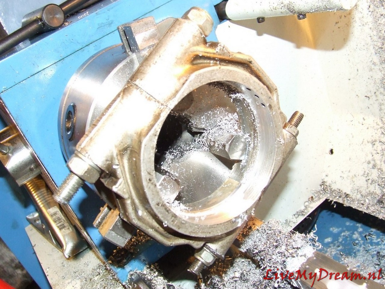
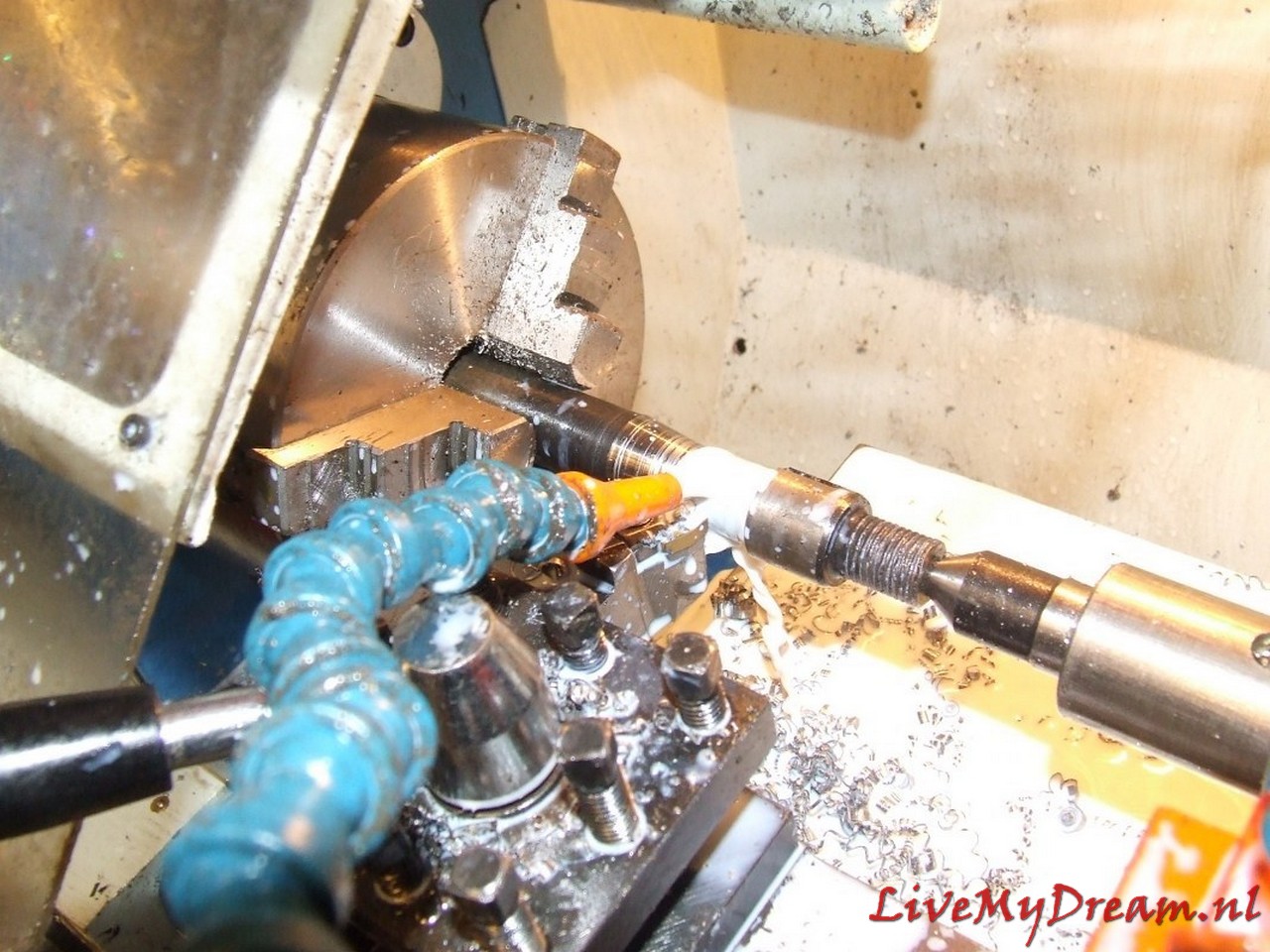
Axles removed and further work on turning the flanges
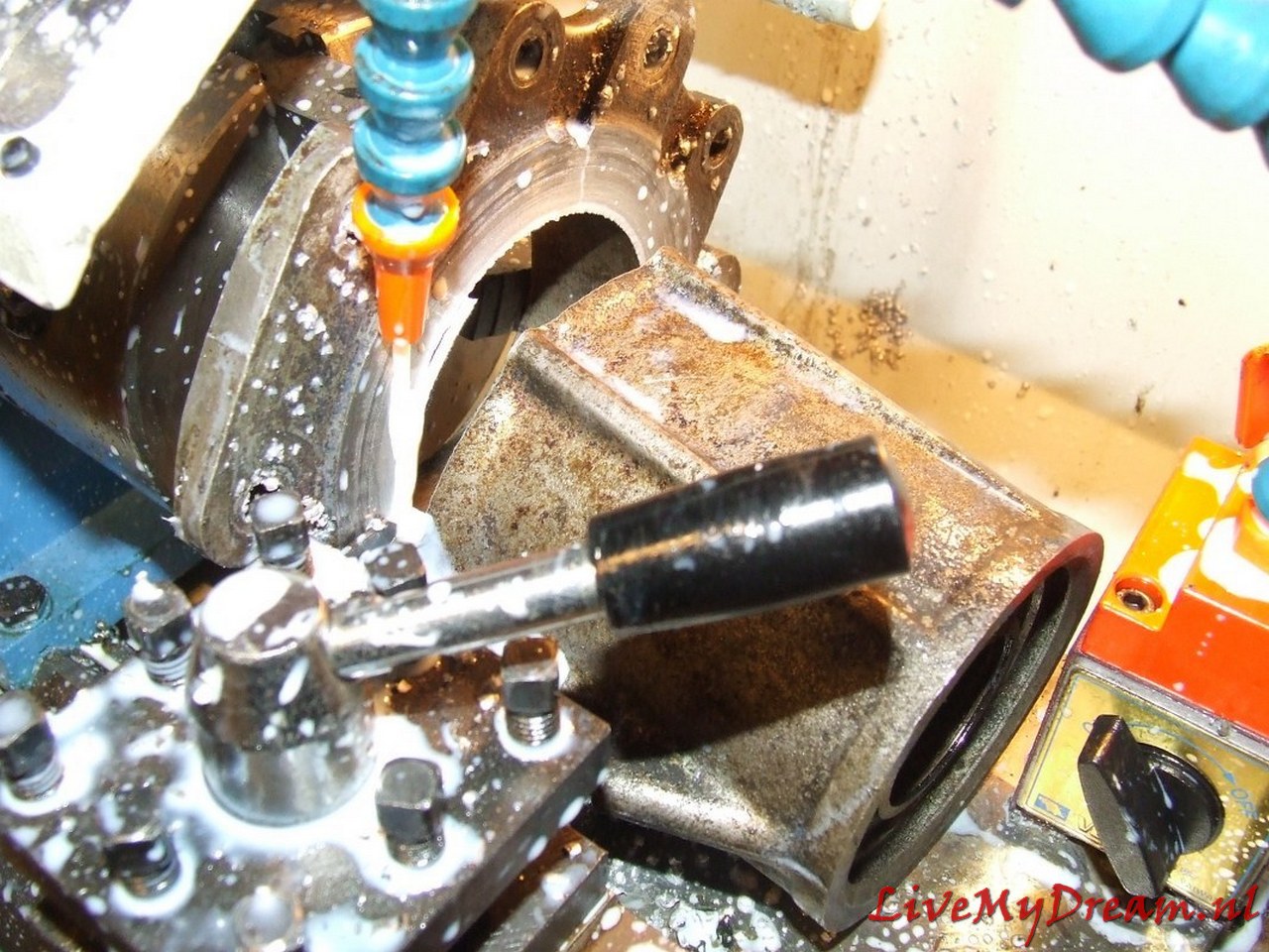
Above is shown how I am turning the bushings for the flanges, here the new bearing and the new oil seal can be mounted.
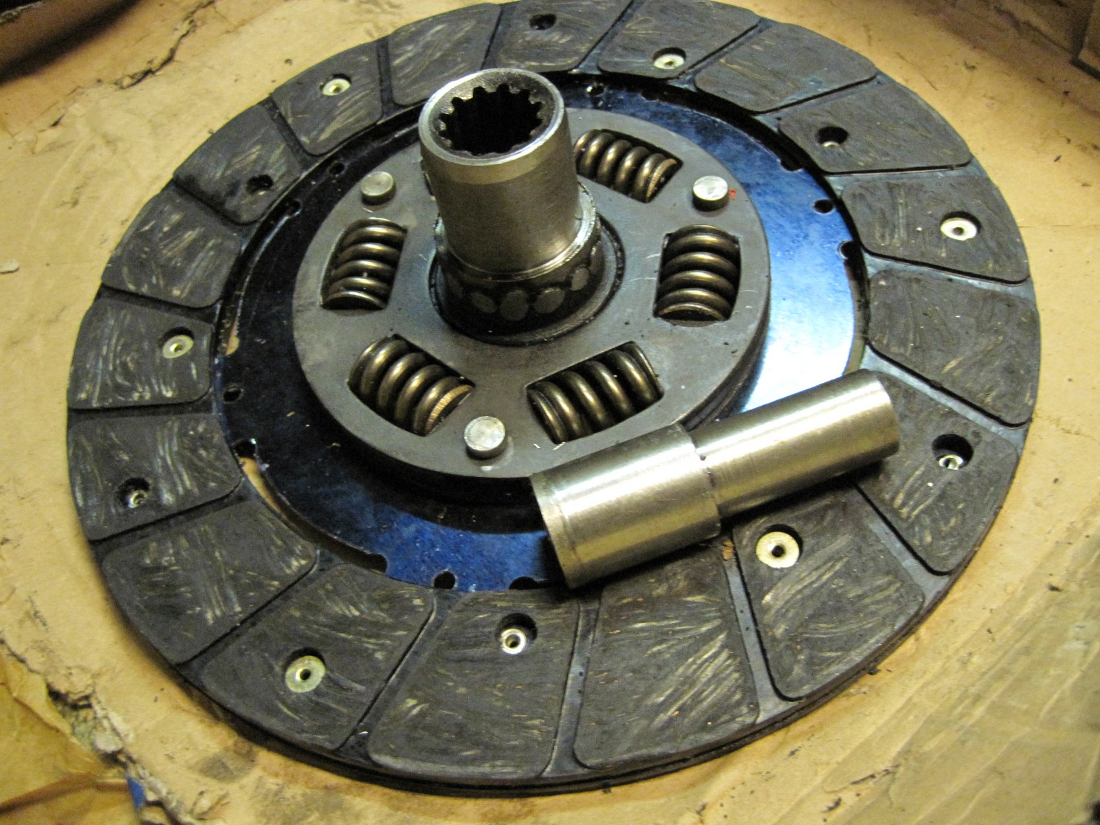
Here the center has been removed from an old ID-19 clutch plate to serve as an extension of another fitting plate.
For convenience I have used a new TA plate for this purpose, an ID plate can in principle also be used but then the keyways must be in perfect alignment so that the plate can continue to slide freely over the primary shaft.
This action is necessary because the primary shaft of the 4-banger is shorter than the shaft of the 3-banger and the keyway of the shaft is just not far enough into the keyway of a standard clutch plate to be able to transfer the force to the plate without damage.
On the picture above you may not be able to see it very well, but the bushings are locked to the flanges with stainless steel screws/rivets so they can’t move or rotate.
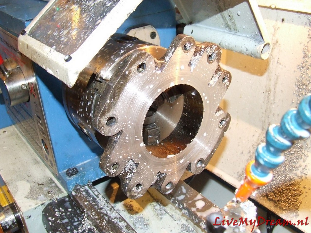
Then the flange is turned off at the outside to make room for the convex protruding parts of the 10mm threaded ends of the axle clamps. this also all just fits.
Above you can see that the flange was not yet turned out….
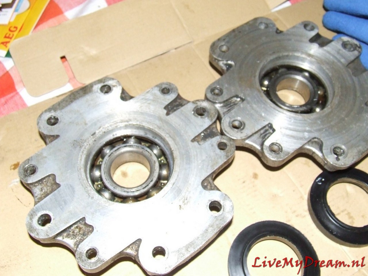
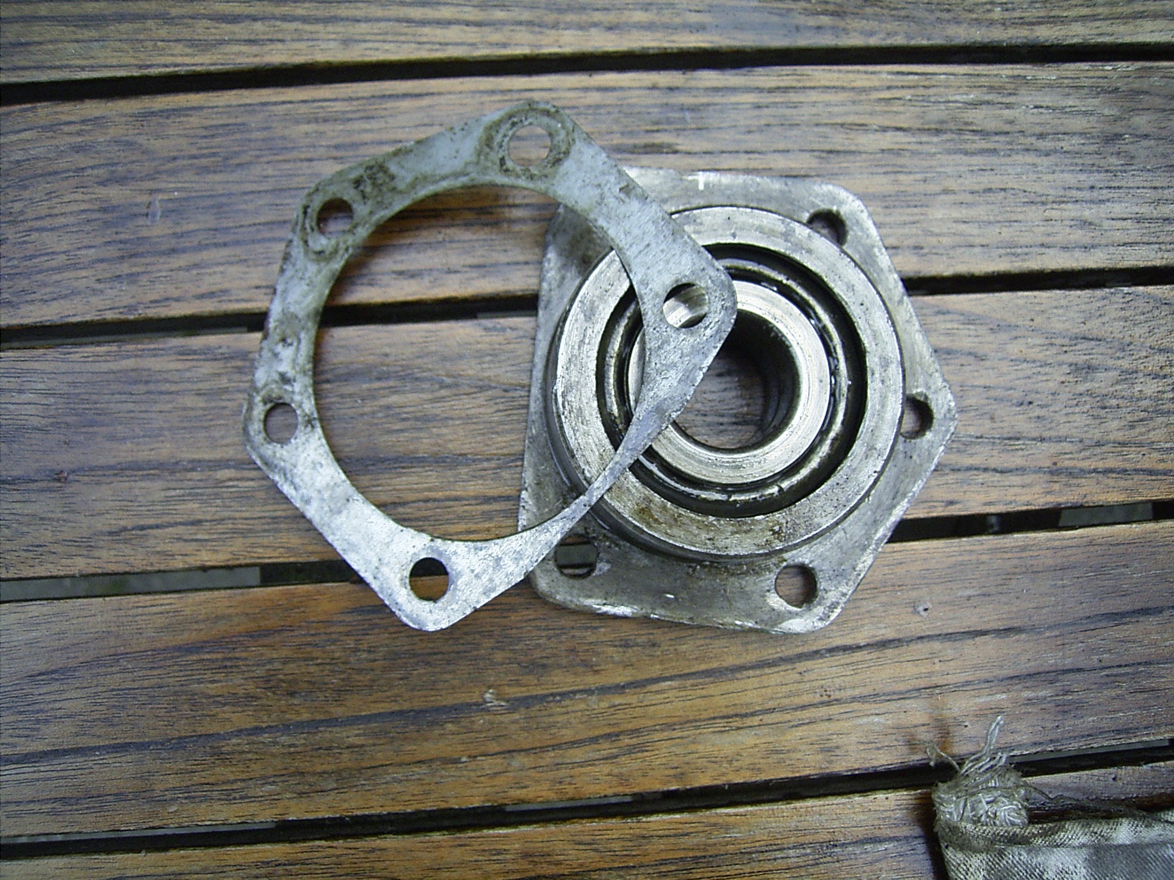
To make the bearing caps fit, they were very carefully turned out to the size of the Timken bearings in counter arrangement in the lathe.
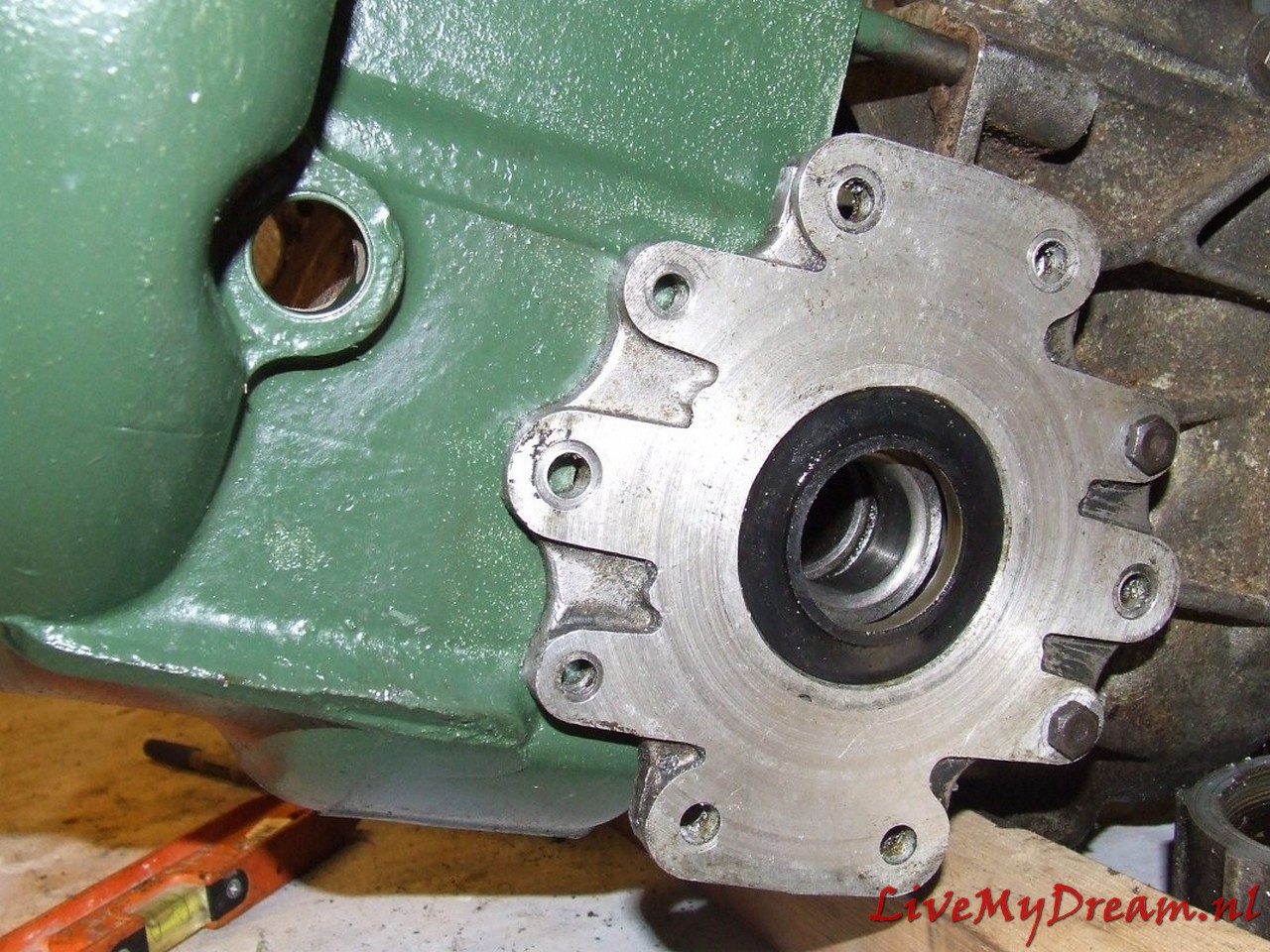
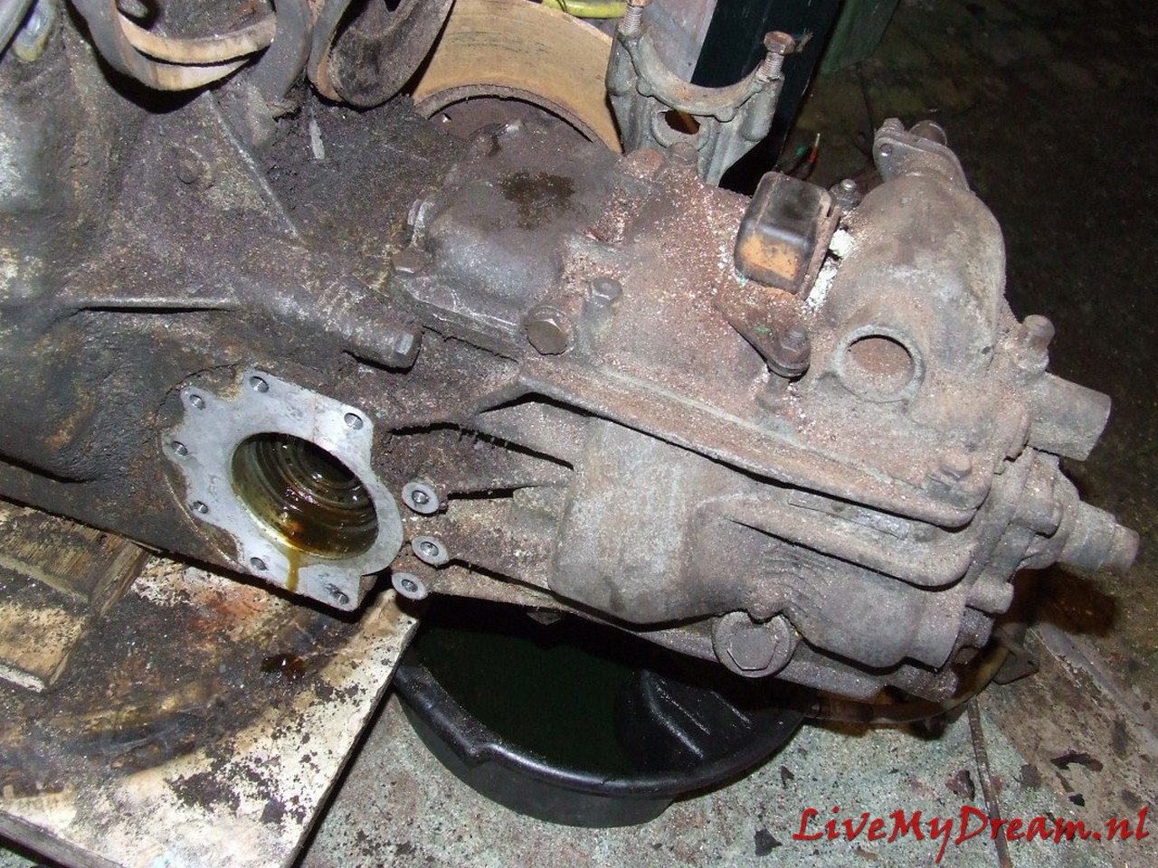
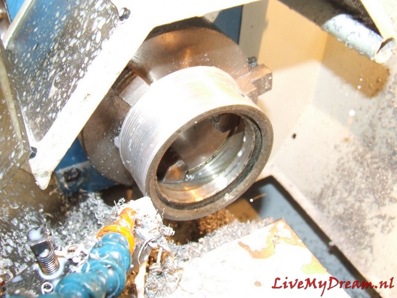
Above you see a turned-off flange with bushing, oil seal and bearing, mounted between gearbox and clutch housing
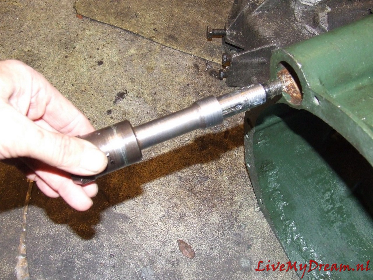
Next job: Extending the drive shaft to the pulley of the ID motor.
The lengthening of this shaft was necessary because I installed a long stroke ID engine at the same time as assembling the 4-speed gearbox.
The drive of this driveshaft on the crankshaft is slightly thicker than on the Traction engine larger and is slightly deeper recessed in the ID engine .
See photo below where the already prepared TA shaft is on top and the ID shaft is lower.
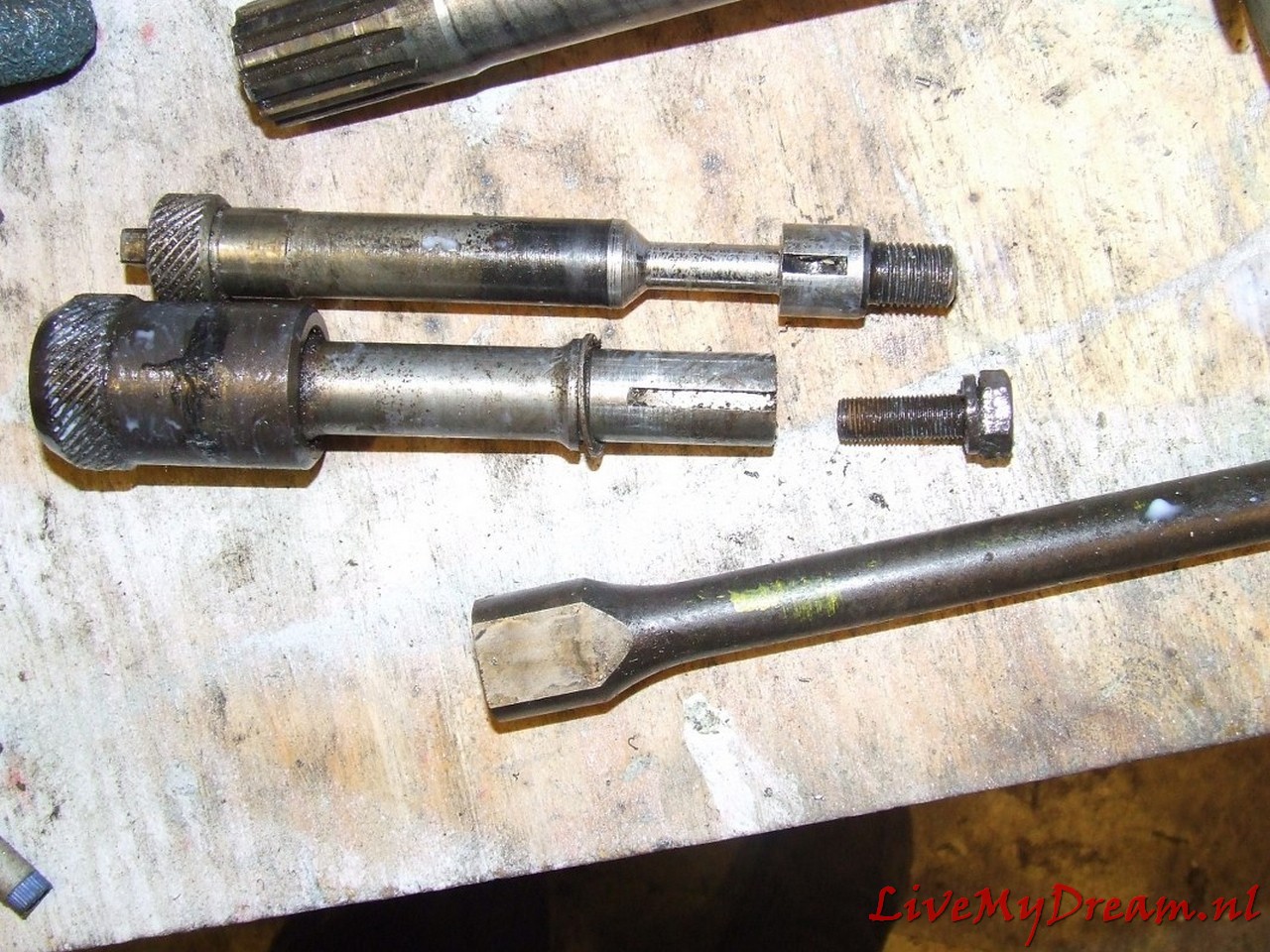
Above: Extended custom pulley shaft ready for assembly
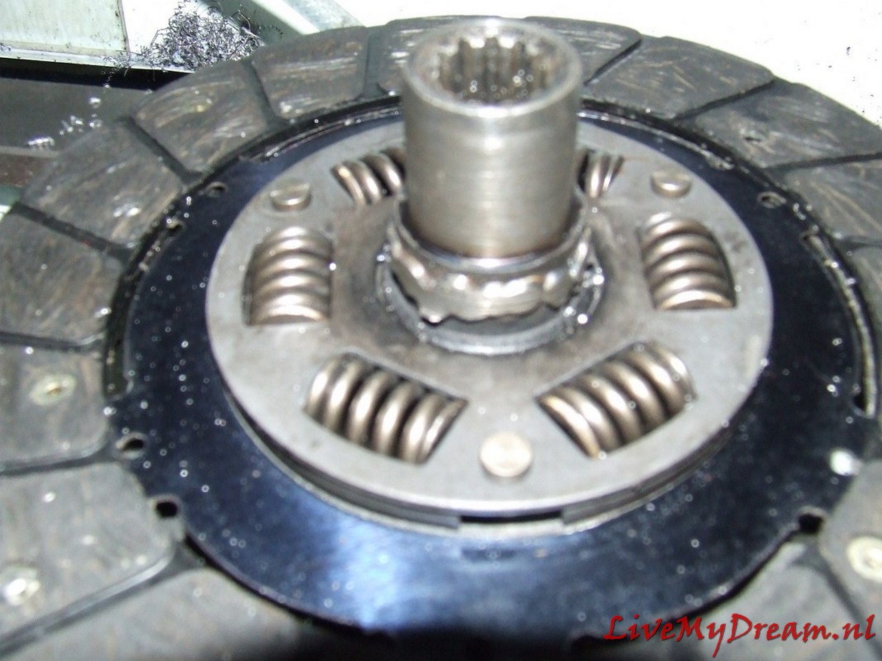
Above you can see the center of the ID clutch pin with ID keyway from a scrapped clutch plate mounted on a new TA clutch plate.
The welding was done with the specially made fitting bushing from ID to TA size tightly pressed into both keyways, this bushing is only removed after letting it cool down completely slowly.
To ensure good adhesion, the welding was first done in CO2 and later grinded out in 3 places, the fitting bushing reinserted and welded again using MIG.
After that I had the welding work checked for swings of the new keyway in relation to the clutch plate.
Fortunately that was well within the norm.
Above the required fitting/shim plate of 4mm thick aluminum is shown as used to make the 100% fit of the TA clutch housing to the ID box.
The main advantage of this solution is that the satellite housing is also free from the inside of the clutch housing and you don’t have to worry about the differential running into the clutch housing.
The reason for this required adjustment is due to the fact that the position (in the longitudinal direction) of the drive shafts on the TA compared to the ID has just shifted by 4mm.
The semi-circular recesses where the flanges on the ID box fit in and where the original oil seals on the TA box fit in are not the same on the ID side versus the side of the clutch housing.
On the TA the shape is exactly the same on both sides.
On the ID box, the hole for the flange is 4mm shallower on the gearbox side and 4mm deeper on the ID clutch housing side.
With a fitting plate between the ID box and the TA clutch housing the non-round shape due to the lack of 4mm is compensated so that the purely round shaped flanges fit exactly in the (again) round hole.
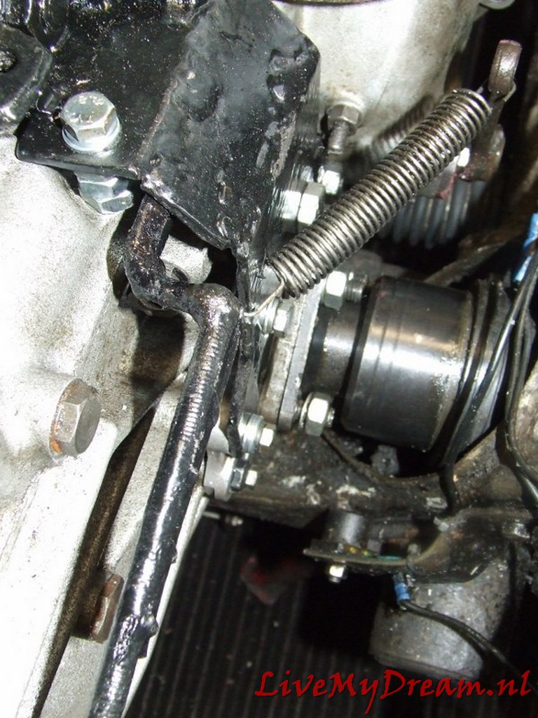
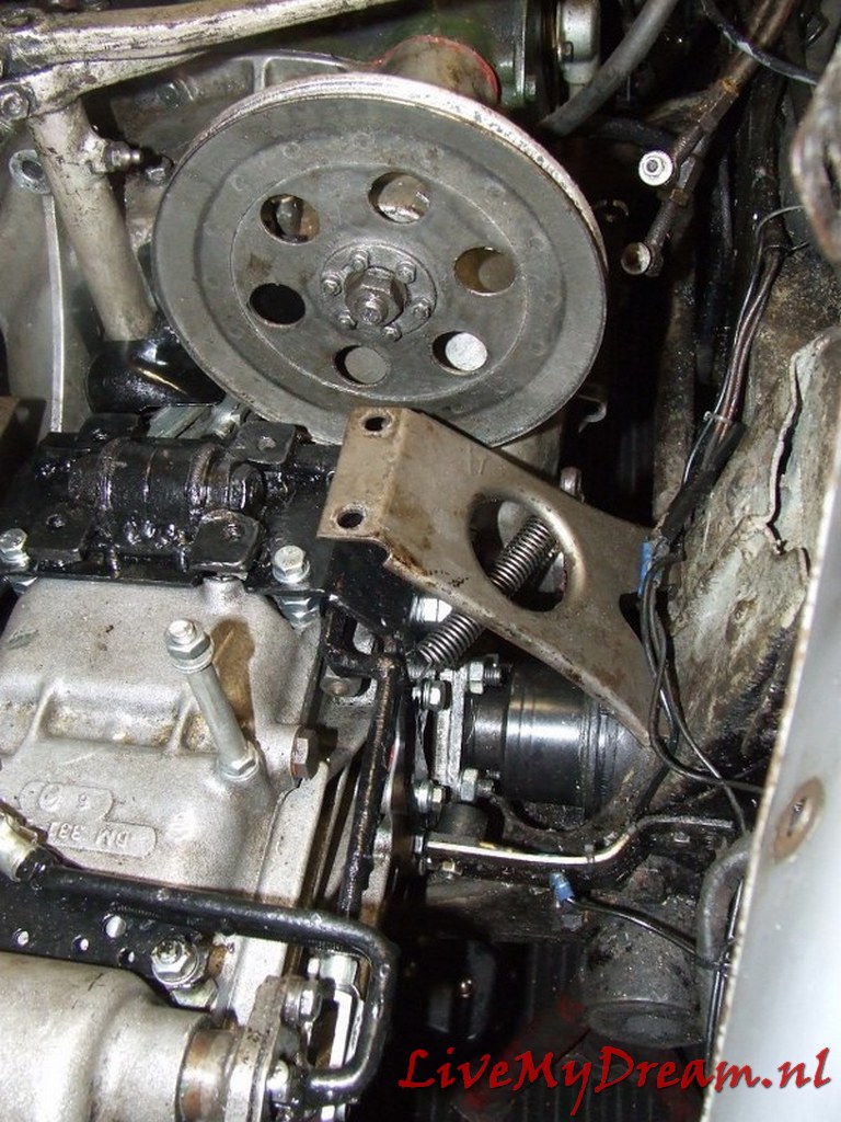
I had to completely modify the scoops of the gear controls at the bottom of the shift tower so that the newly developed rods can be operated for the ID box.
It took some thinking and trying but this solution works great!
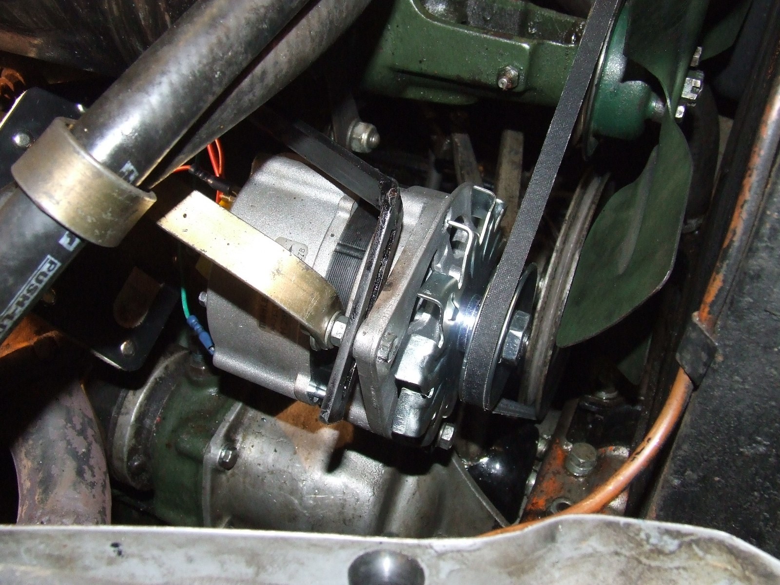
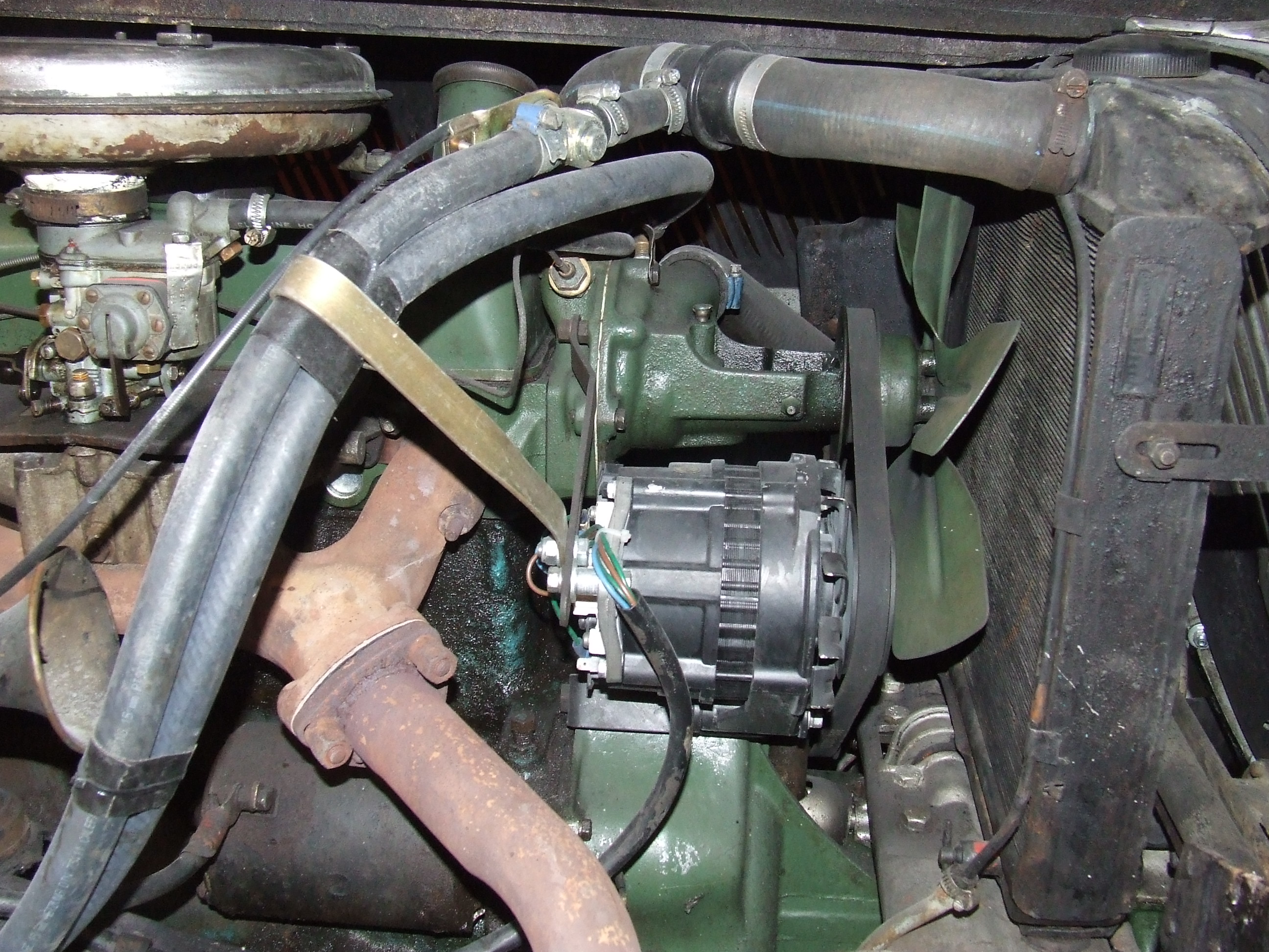
As you can see in the picture, the ID pulley only just fits next to the right-hand scoop.
By using this pulley I immediately switched to a narrower V-belt.
That meant changing the water pump pulley, and mounting a 12 Volt alternator.
Above is the 4 mm gasket plate in detail.
During the assembly process I used thin paper gasket on both sides of the gasket plate.
That turned out to be the only way to get everything leak free.

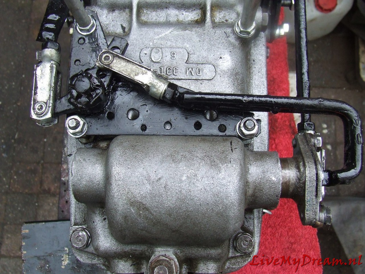
The switch rods between switch tower (left) and transmission levers (right) to the selector in detail:
Small additional challenge with me was that due to the installation of the ID engine and- associated cylinder head- the carburetor suddenly ran in the path of these switch rods.
Using a water pipe bender, I was able to keep the shift rods exactly clear of any fixed engine parts and it all just fit.
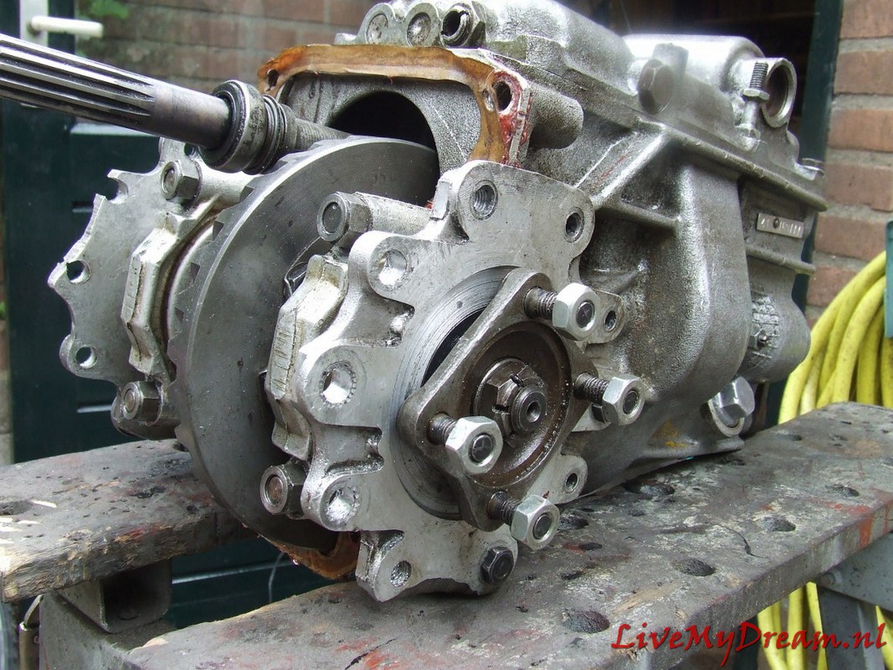
The gearbox without control rods mounted on the clutch housing.
If you look closely, you can see that here I still worked with the ID insert shafts, which I had shortened.
In the end, this solution did not work because the welded shafts kept breaking off at the weld.
In itself, this solution is possible, but then you would have to make (or have made) new shafts].
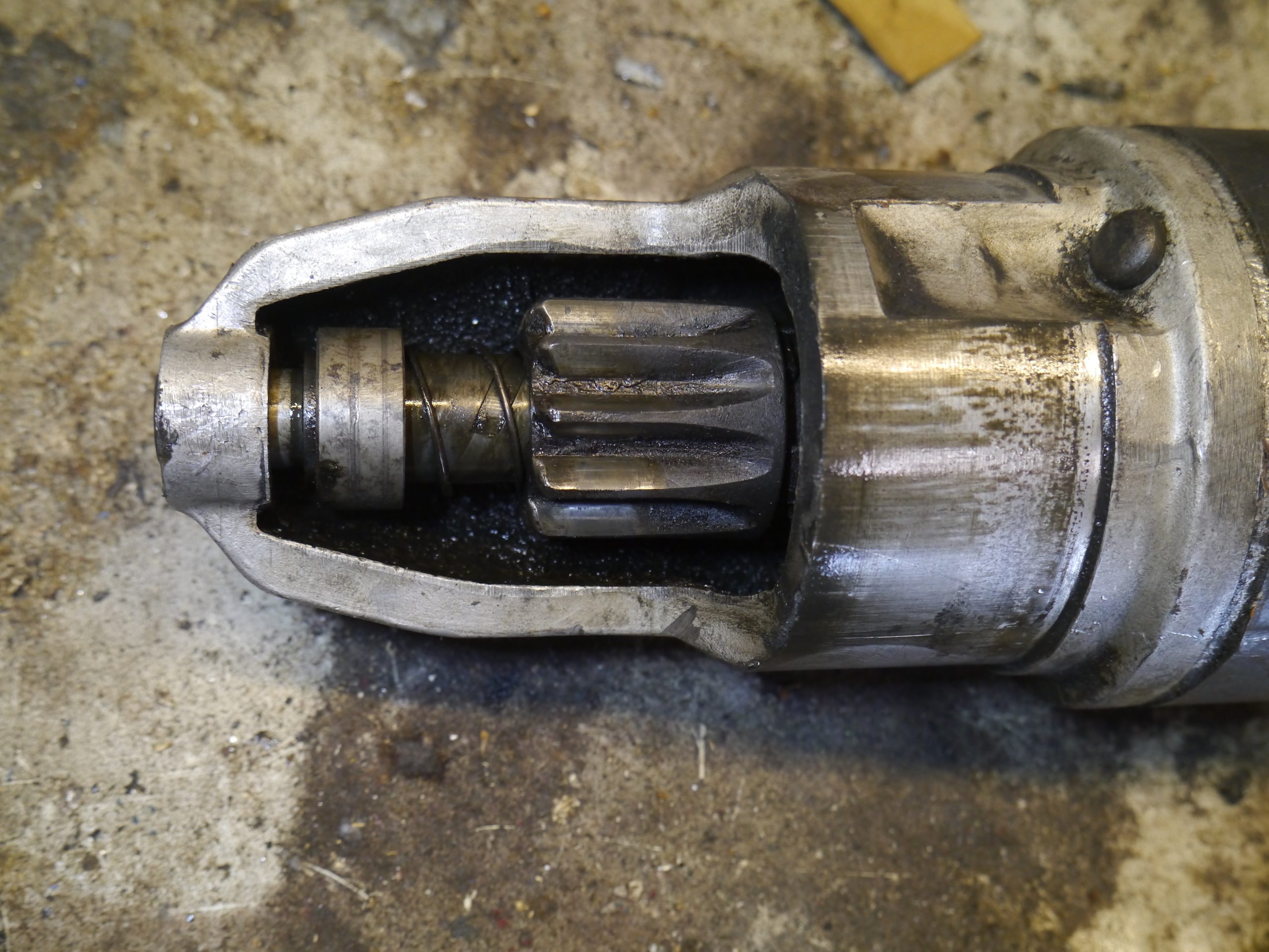
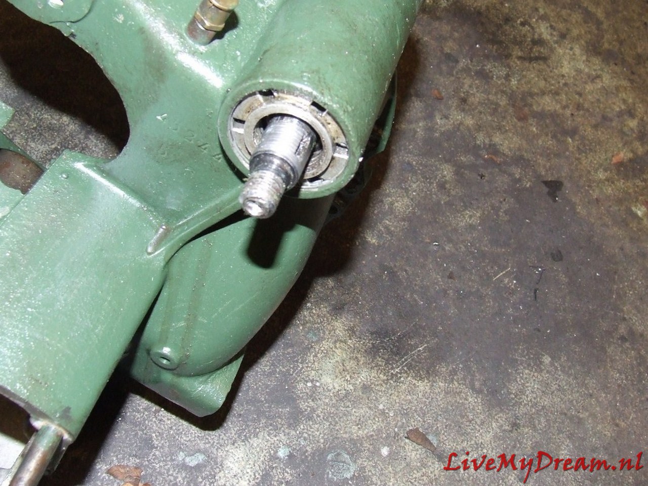
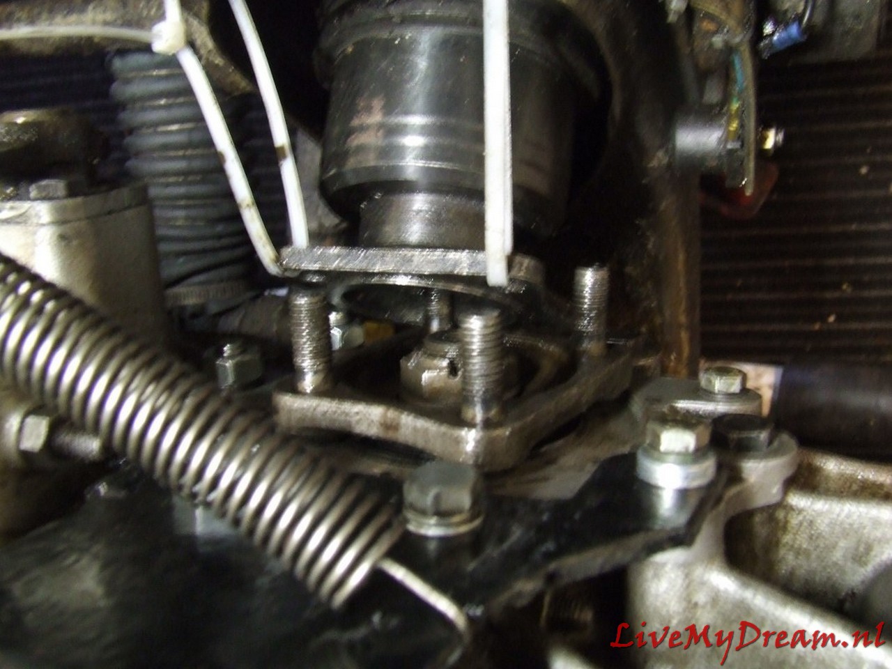
Above you can see the extension of the primary shaft by means of a bushing that comes on the primary shaft.
This bushing comes between the primary shaft and the top bearing of the crankshaft.
The goal is to keep the primary shaft from swinging.
The bushing in the photo was my prototype.
There are top bearings with different inner diameters in which the primary shaft fits and so here too practice was (again) my teacher.
Clutch plate in the (equally mounted) attachment ring of the newly installed diaphragm pressure group
And the entire pressure plate with clutch plate mounted and the keyway of the clutch plate protruding outwards
Clutch housing with M10 bolts for securing the flanges.
The M10 bolts are mounted through and through in the cheeks of the housing.
Previously I experimented with other solutions but with tapping, mounting bushings and the like I did not get it sufficiently oil-tight.
In the above manner with rings and gaskets it is perfectly tight!
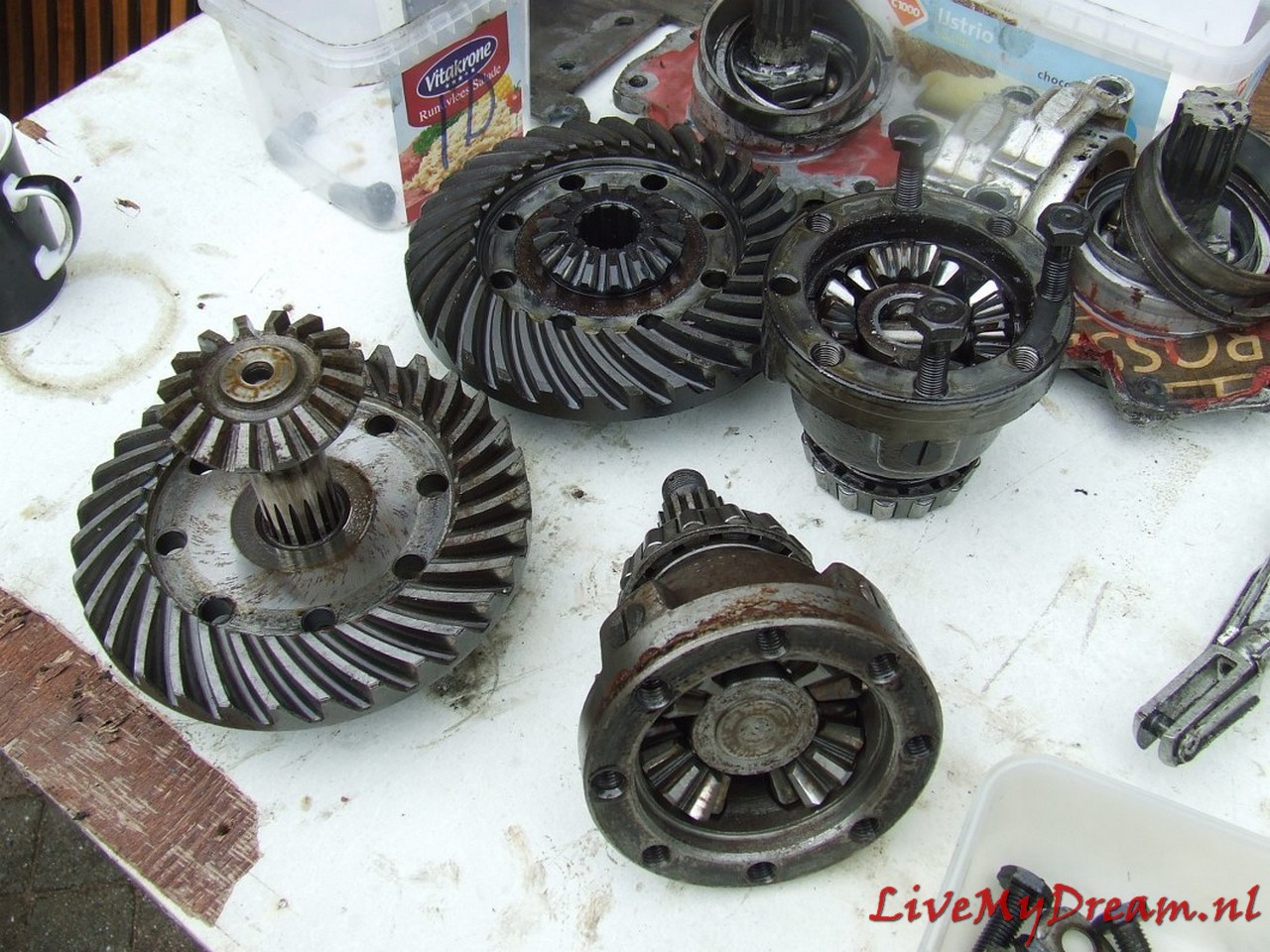
This was a bit of a job: Making 1 new one from the donor parts of 2 differentials.
In itself not difficult when you think of what will fit:
Pinion from ID is used, so the satellite gear from ID must be used.
The outgoing shafts from the TA are used so the satellite gears from the TA must be fitted.
The thinner output TA shaft is placed in the satellite gear of the ID so a fit bushing must be pressed into the ID satellite wheel so the TA shaft can rotate freely but tightly in it.
The Satellite housing of the TA is used (bowl-side where the gears are) with the fixed (TA) shaft attached.
In the picture above you see the bottom left satellite gear with freely rotating output shaft.
Bottom right you see the bowl part of the satellite housing with the satellite gears and fixed output shaft.
The original TA differential works with bucket-shafts with keyways on the outside on which the TA bucket-shafts can be mounted externally.
The advantage here is that this allows you to easily replace the large retaining rings of the TA box.
So in the photo above, the bottom differential is the TA differential.
Above: Finished and assembled differential. You can see the fitting bushing sitting nicely
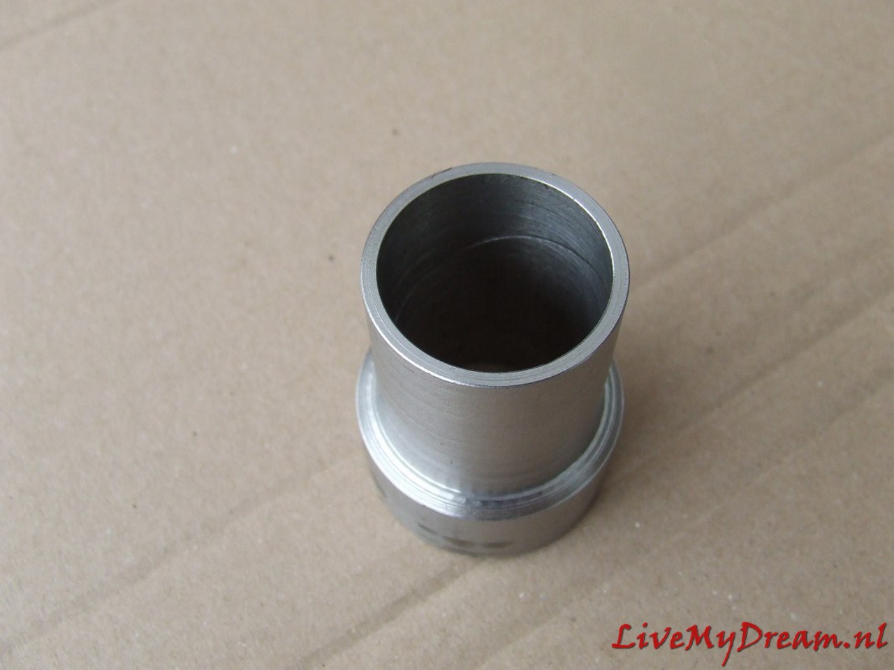
Above you can see the made fit bushing with oil groove on the free turning inside.
Timken bearings tighten but not too tight….
Converted switch selector/levier, in the experimental phase.
Turn shaft chuck to commercially available bearing size
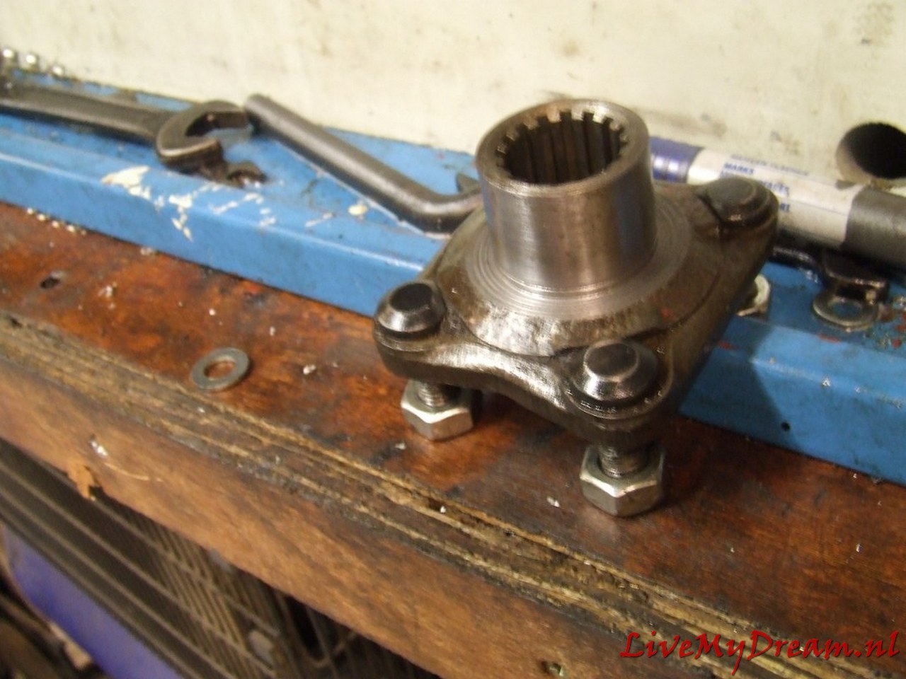
And the turned down result of the axle claw of the TA with inner splines.
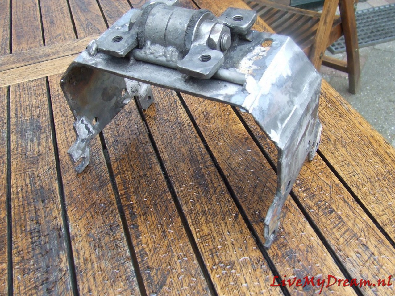
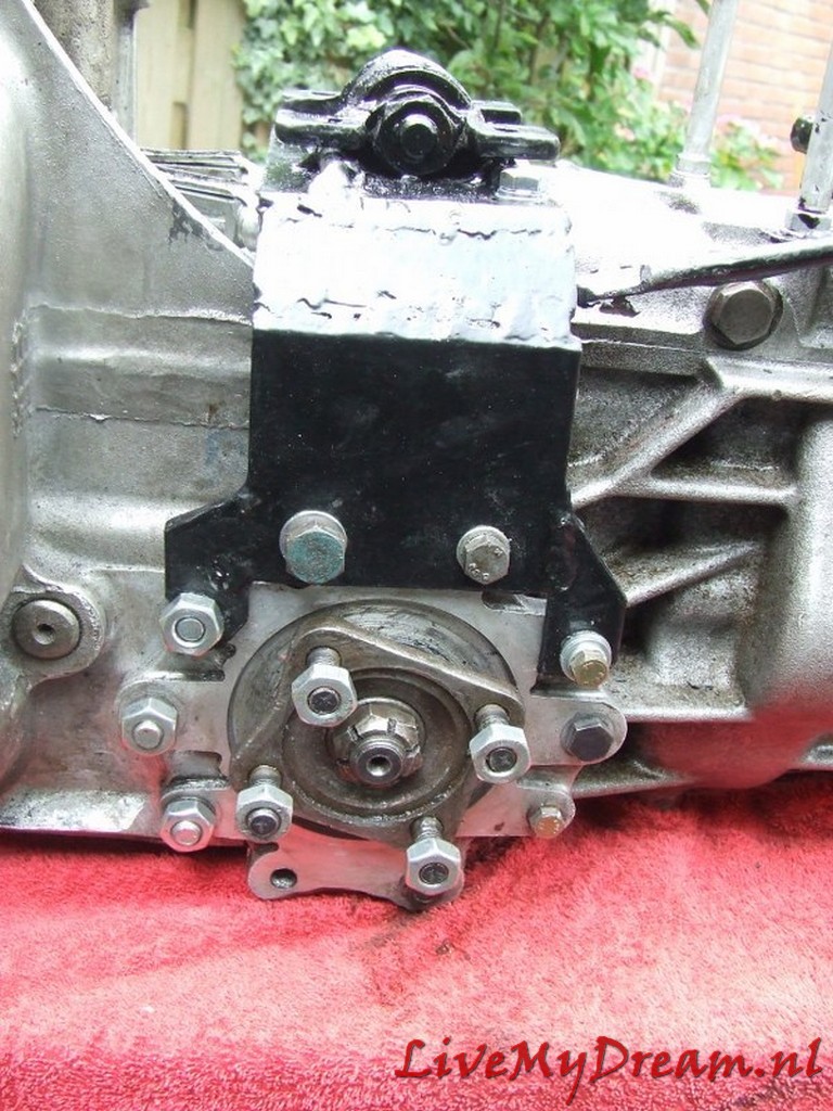
Mounting Bracket.
I chose a very robust setup, since the motor/box/drive shafts are all suspended from this point.
In addition, I chose to simply reassemble the cross pieces of the drive traverse to maintain sufficient strength.
Please note above: On the underside of the flanges, I have ground away about 2 cm of material on both sides.
This is because these points protrude from the original TA body.
This means that they come up against the cradle just above the passage of the drive shafts.
So I had to remove some material. I can’t remember the number of times I have assembled and disassembled the gearbox, but at least it was so many times that I can now do it blindly and very quickly.
Above again the removed material: Handy to do BEFORE mounting!
Bearing for the axle claws. I heated this part in the oven at 60 degrees before final assembly.
Ready.
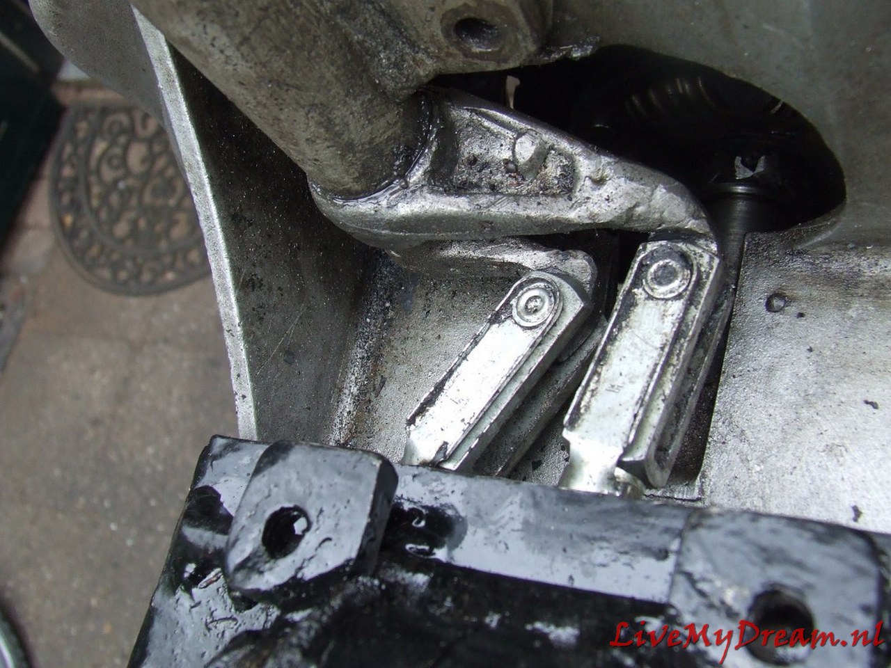

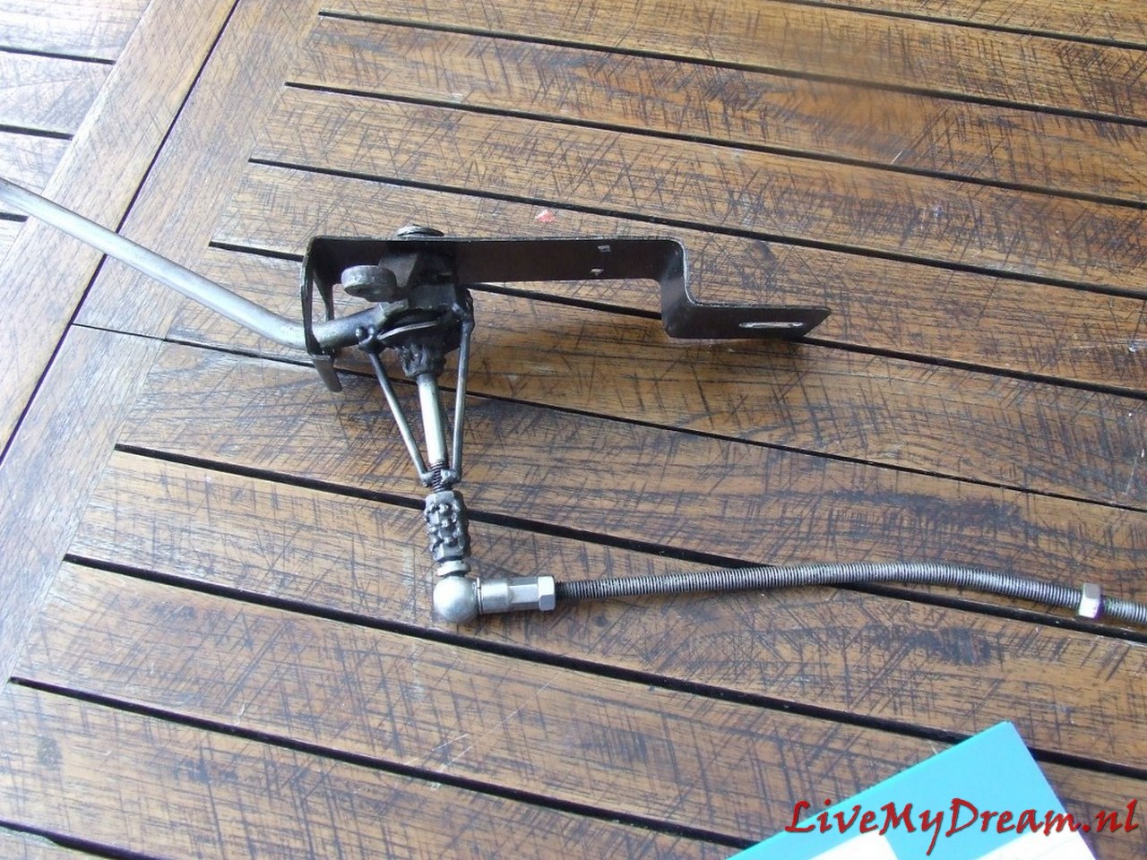
Shifting axles. Left the up/down movement of the shifter and right the left/right movement….
Picture was taken during assembly: nut still tightening and all.
At the bottom right you can see the sensor of the cruise control hanging away.
The magnet is placed under the nut, which is still loose, with a bracket so that the sensor can see it at every turn.
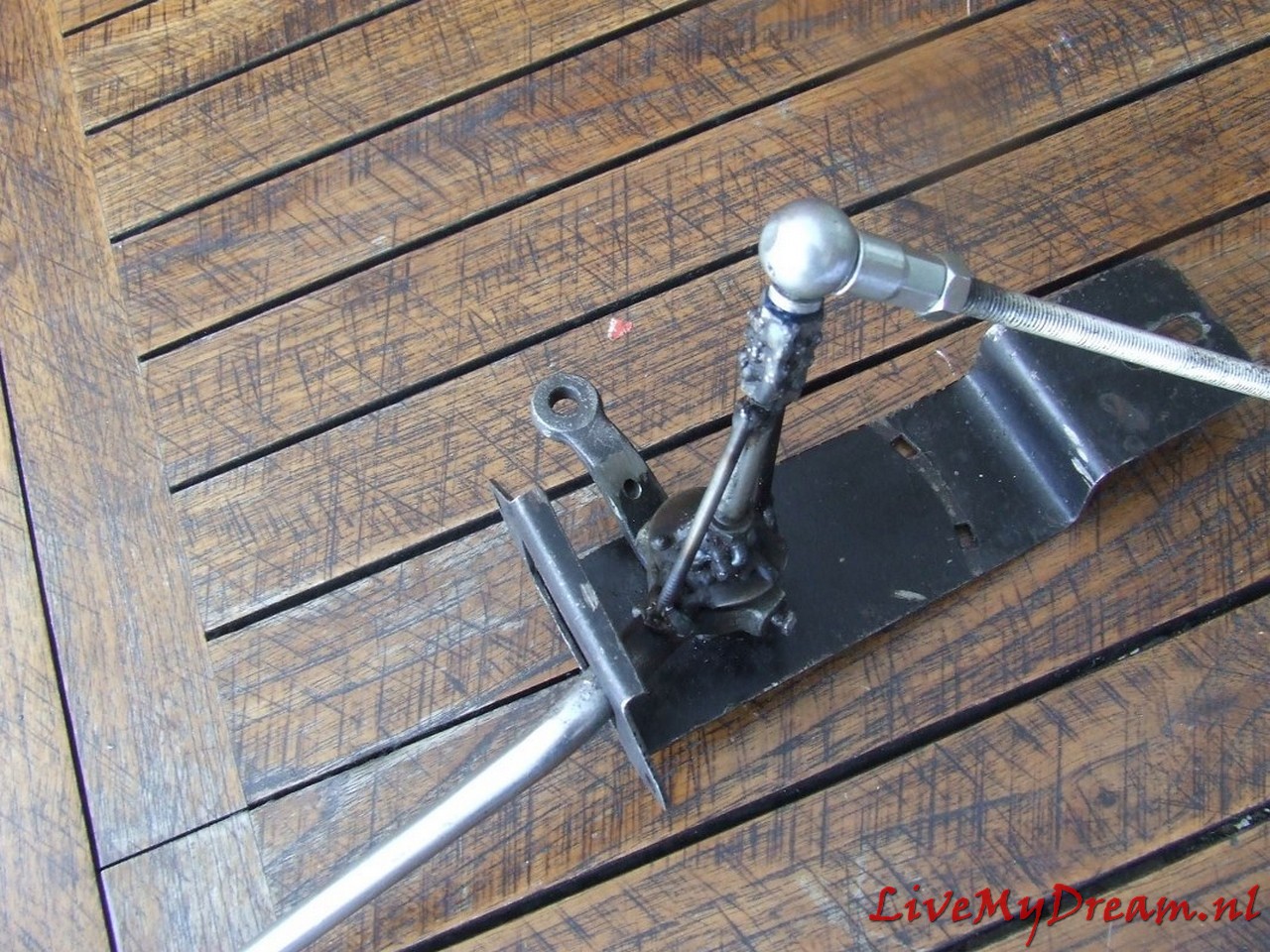
Above the modified spoons from the bottom of the switch tower.
And the final result!
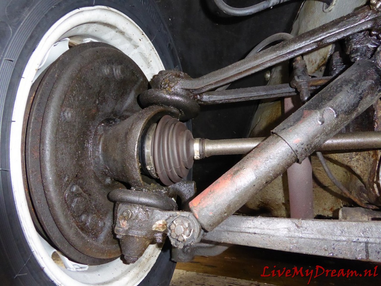
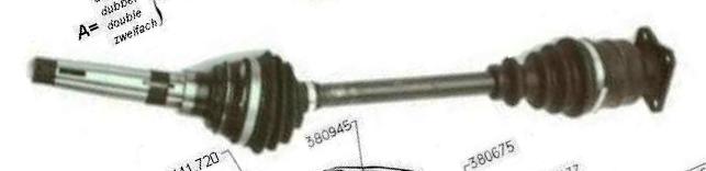
First, the original shafts were overhauled, but when the 4-speed gearbox got installed, double homokinetic drive shafts were installed at the same time!

Above: At the time of purchase, Below: At the MOT inspection

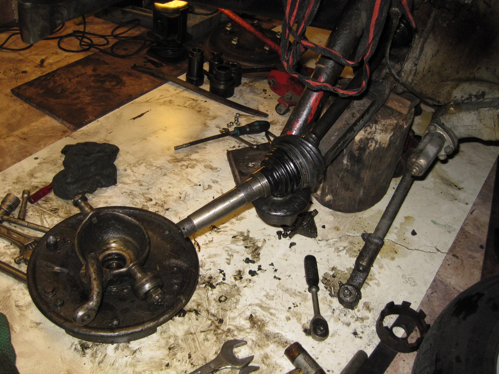
Above: After replacing the old driveshafts with the driveshafts fitted with dual homokinetic joints
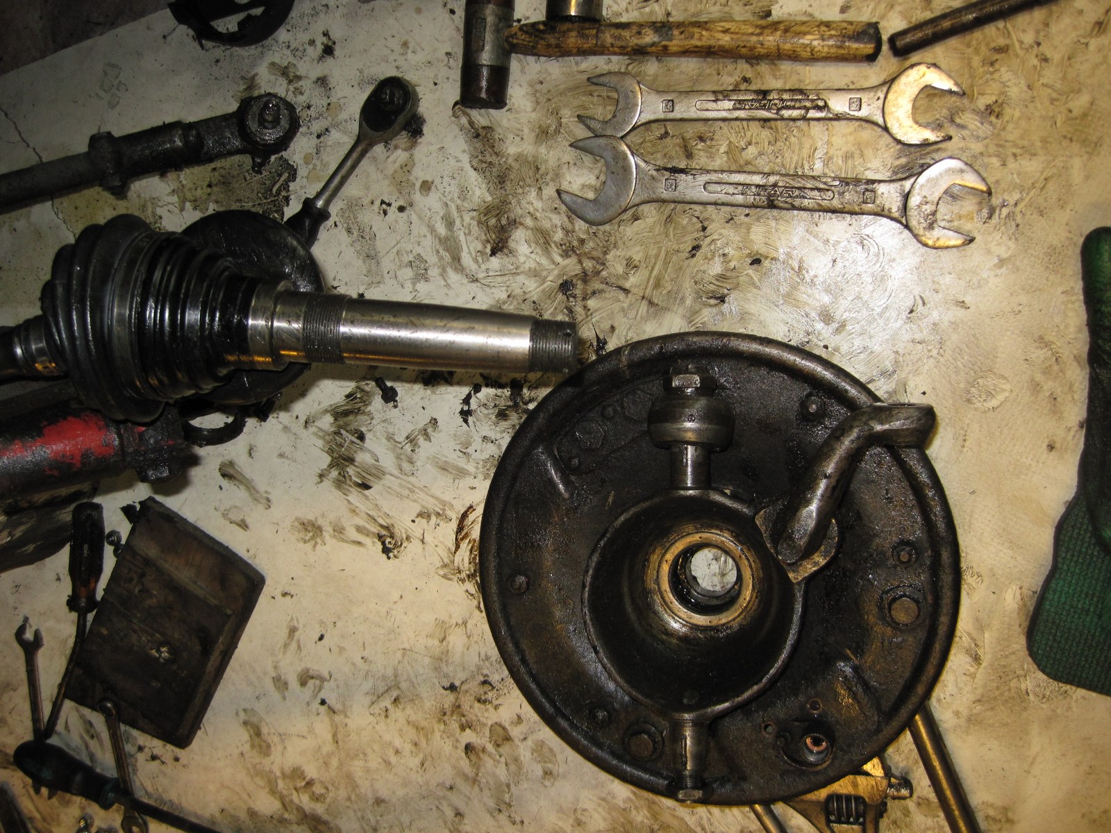
Assembly of the new axles whereby really everything has to be loosened….
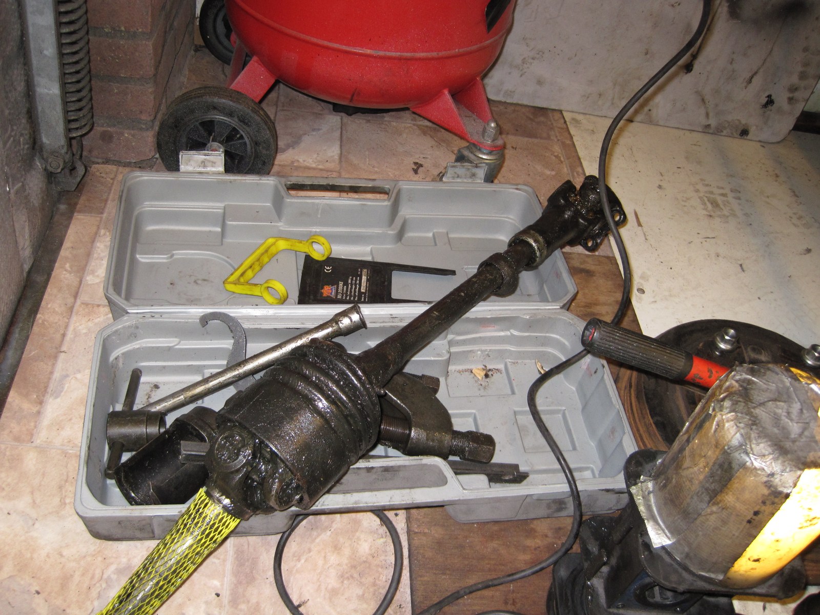
Above the old axle

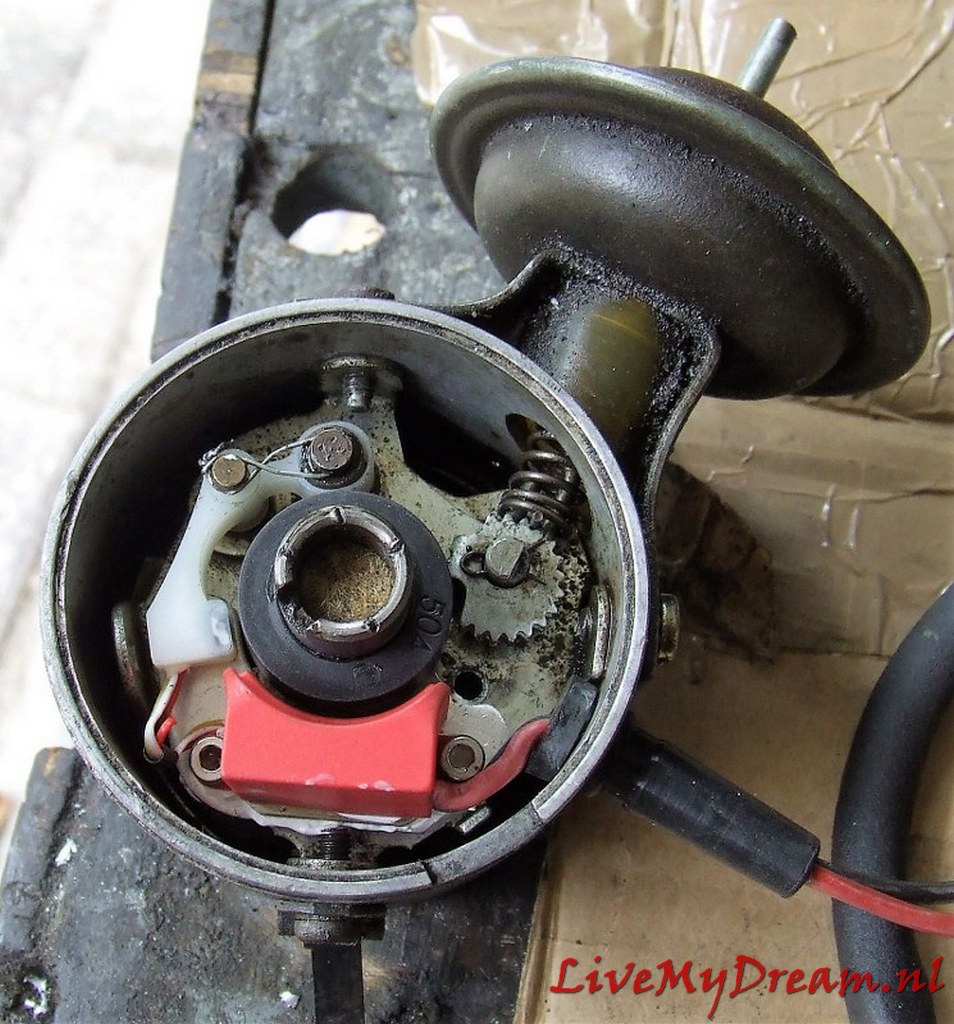
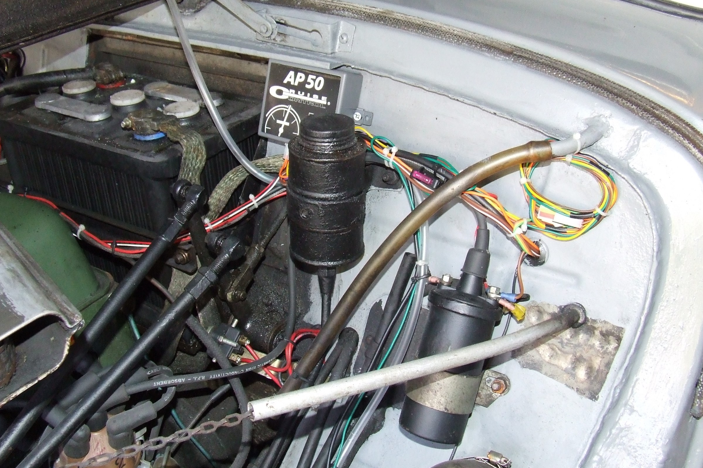
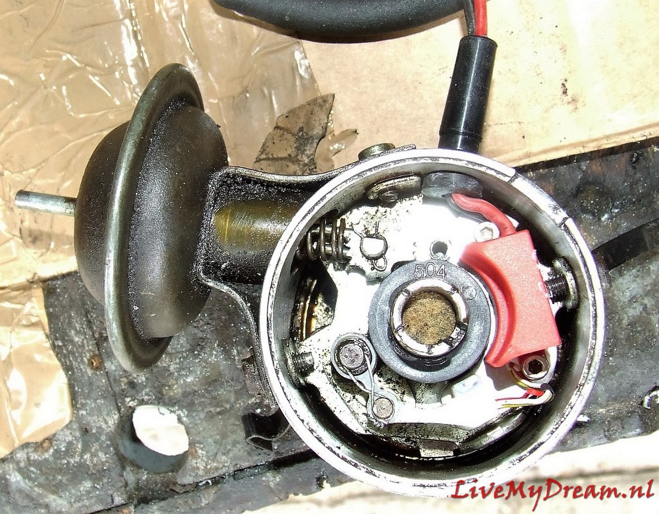
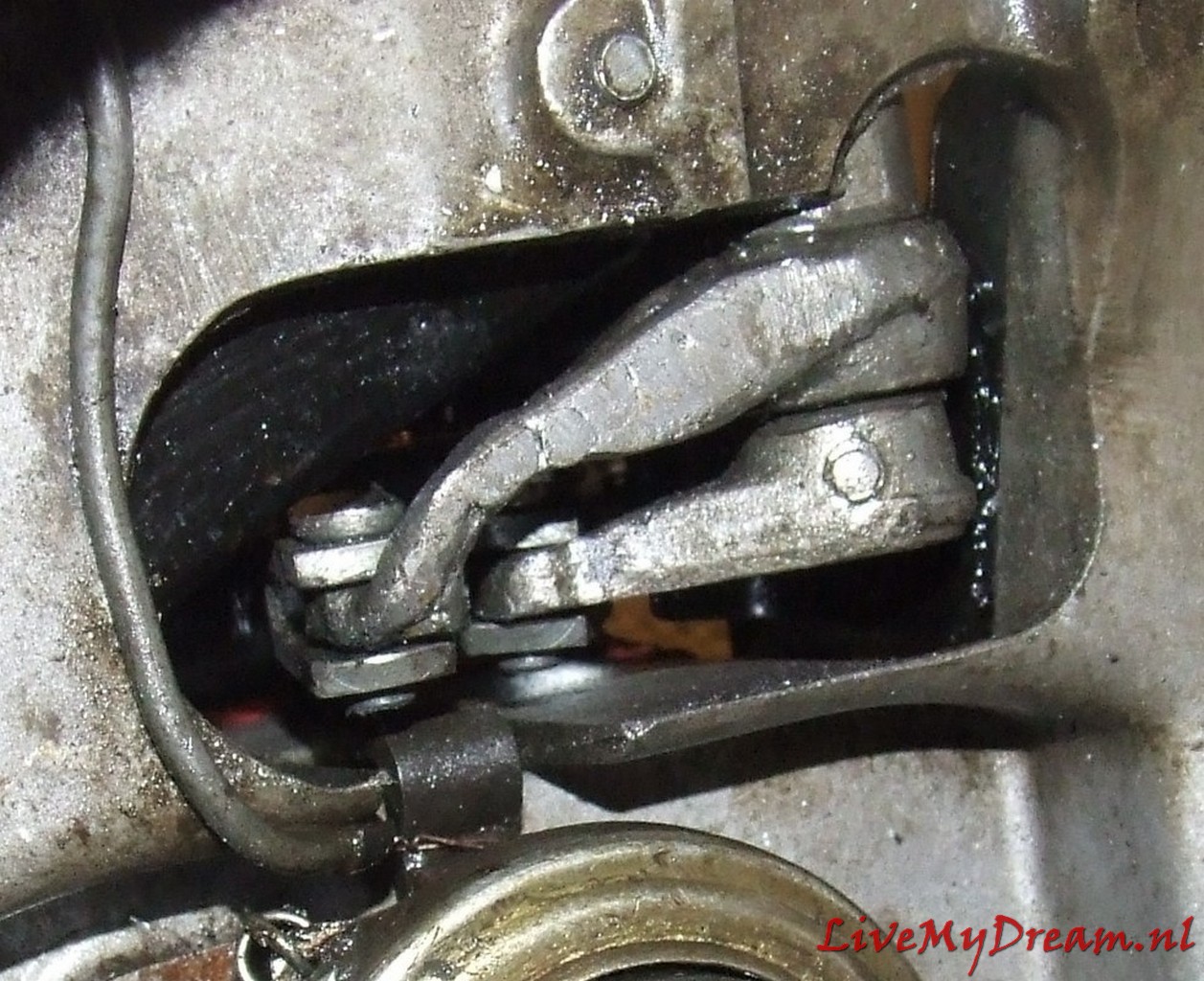
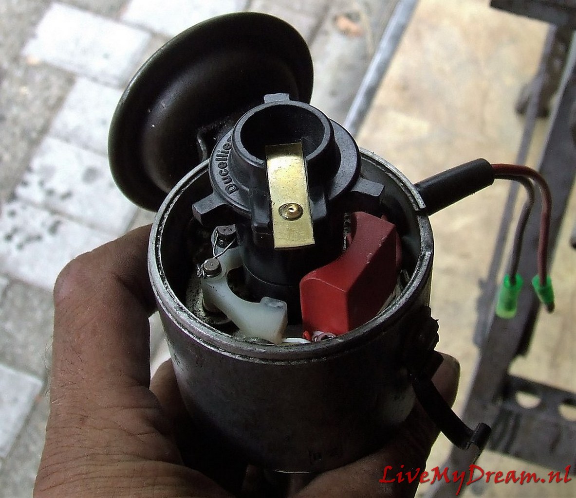
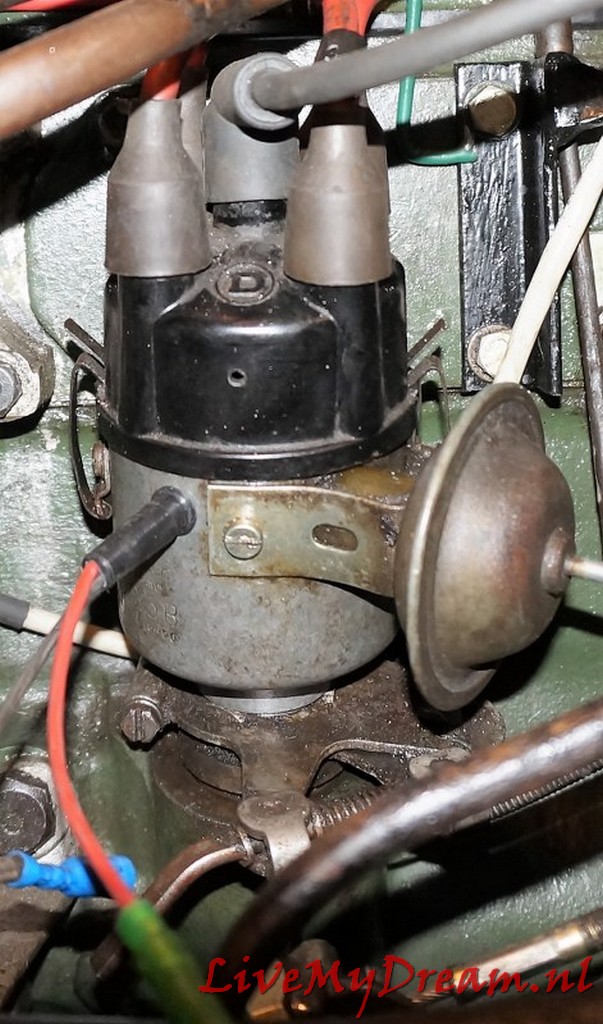
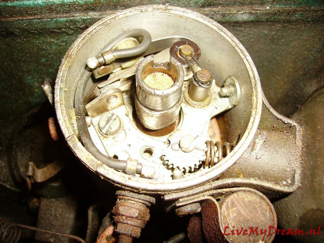
Really crappy, I don’t have another word for it: The old contact point ignition with its coil. I tried 3 of them on 6 volts and the combination of 6 volt battery, starter motor and points always gave me trouble, both with cold and hot starts. So I installed an electronic one, and NO 123 ignition. Just an English ignition, specially for 6 Volts OR 12 Volts. First installed with the 6 Volt installation and it worked perfectly. Still does, but now on 12 Volts.
After 13 years of standing still the first MOT in 2006, right after I bought the car, was quite a challenge. Besides a stuck engine, broken gearbox, defective exhaust, brakes, steering knuckle covers and the like, there was also a lot of work to be done on the electrics.
TA 2006-2012 picture overview


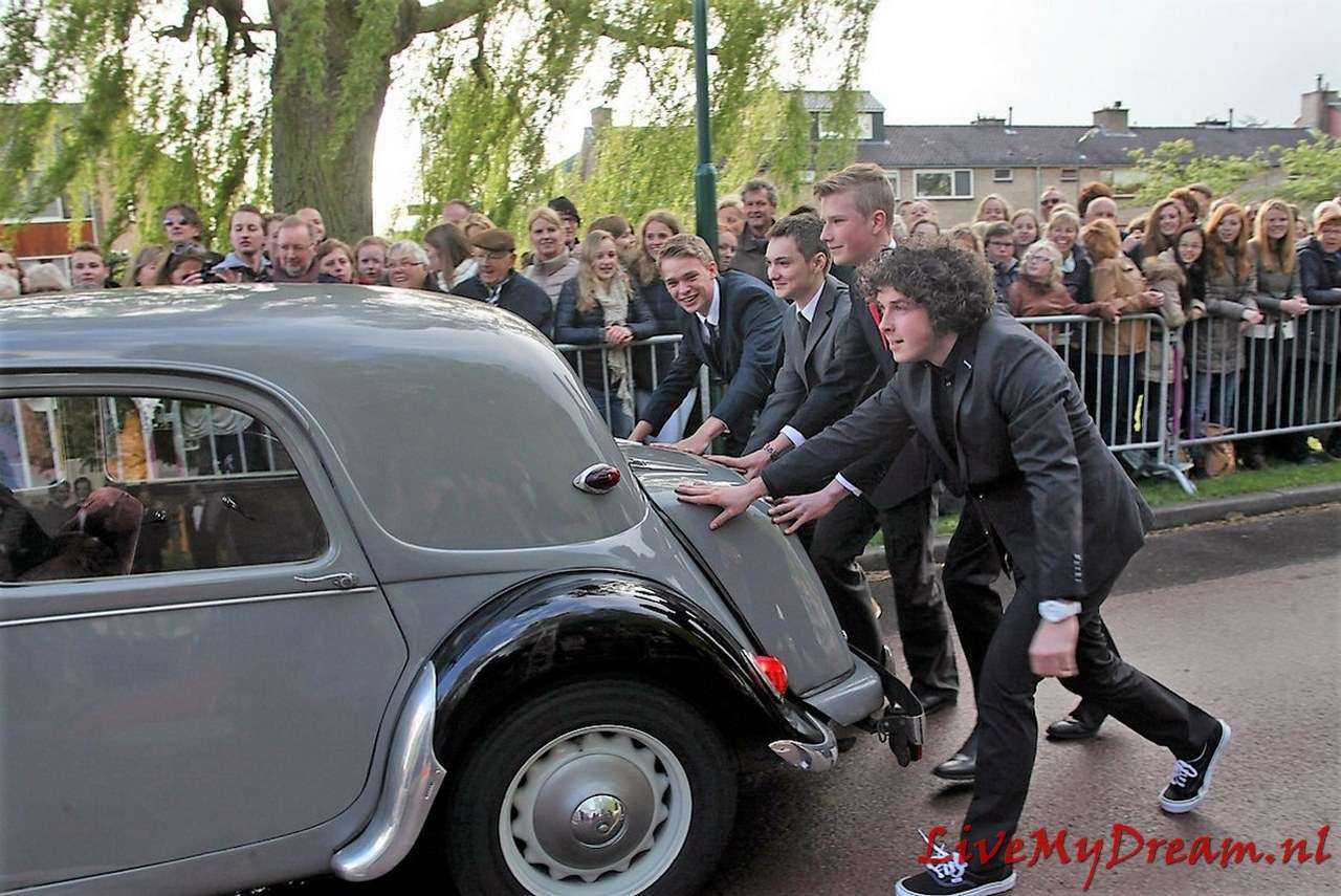
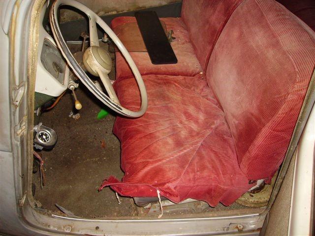
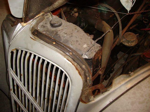
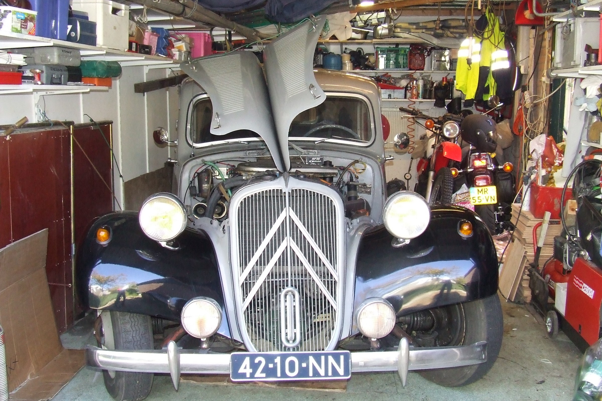
June 2006: In any case, there was quite a bit of visible sheet metal damage and…, the engine was stuck. The brakes didn’t work, nor did the handbrake. The front bumper was in the cab. The chrome present on this car seemed to be completely depleted, including the associated rust marks. In the trunk that was barely open there should still be some spare parts. Included were new front bumper supports, as the front bumper had completely rotted off at the bumper supports. The good news: The bottom and the attachment to the engine suspension front coque was fine, the doors were good and above all: the body was hard all around. Nice detail was that the tubes on all visible parts had the familiar small plastic caps, which indicates that this car once had a full anti-corrosion treatment, including injected tube chassis. Hence the cool bodywork in the places where a TA often seems to be bad. The underside of the chassis is also completely covered in a thick layer of gunk, possibly ML, Dinitrol or tectyl. This layer is peeling off in several places. In any case, it did not prevent the fenders from rusting through. At the places where the water splashes against the fenders when driving, they are well rotted through. Anyway, the sale was closed and on July 1 I went to the previous owner with a car ambulance and my purchase price. The car has a Dutch registration and was built in 1955 but imported into NL later. And… There you go, out for the first time with my own Traction Avant. It was very hot and there were quite a few oldies on the road on Sunday morning. I could already see myself driving one of them. But that will take some time, because I experienced the harsh reality after I got the car into the garage which required quite a bit of help in the form of pulling and pushing. The first striking feature of this car is its respectable length which leaves little room for tinkering at the front and rear. The garage is 5.3 meters long and 3.3. meters wide. The width is possible, but in the length I have moved the stuff in the back of the garage to another place. The motto for now is to keep as much junk as possible out of the garage.
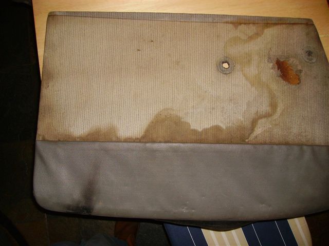
And… here we go: The first inspection! First I sprayed some release spray in the spark plug holes already removed from the spark plugs, let it soak in for a few minutes and crank… hang on. No movement at all. Repeated the action and then every day for a week, sprayed and hung on the crank, also rocking back and forth in 3rd gear. Nothing at all. Asked advice from experts. Advice is: Leave it for a few weeks with a lot of rust remover in the holes and occasionally move it around a bit in its gear. I wonder if this will be of any help after my vacation, where I am now writing this. Then let’s highlight the other issues. All moving body parts were treated with rust remover because everything was more or less stuck. At least that worked. Found some interesting things in the trunk so I now own the following extra: Front bulkhead heater (connects to cooling circuit) with covers and air hoses; Unicode 3 complete carburetors with membranes and nozzles intact etcetera; Fully complete used workshop manual; Olyslager booklet for the 11 and 15 ; Complete gasket set including new head gasket A large number of bolts and nuts Hoses for everything Clignoteur / lamp holders and defective caps Bulbs Relay The missing wooden window crank knob from the left rear Blankets Sleeping bag Floor covering and so on After careful selection, my wheelie bin was packed and I was left with 2 boxes of parts that might be useful in the future. Inside the cabin, I discovered that the original upholstery that is under the red ribcoard covers still looks pretty good. It’s a different story with the lining of the doors where the holes for the control handles are located. So reupholstery.
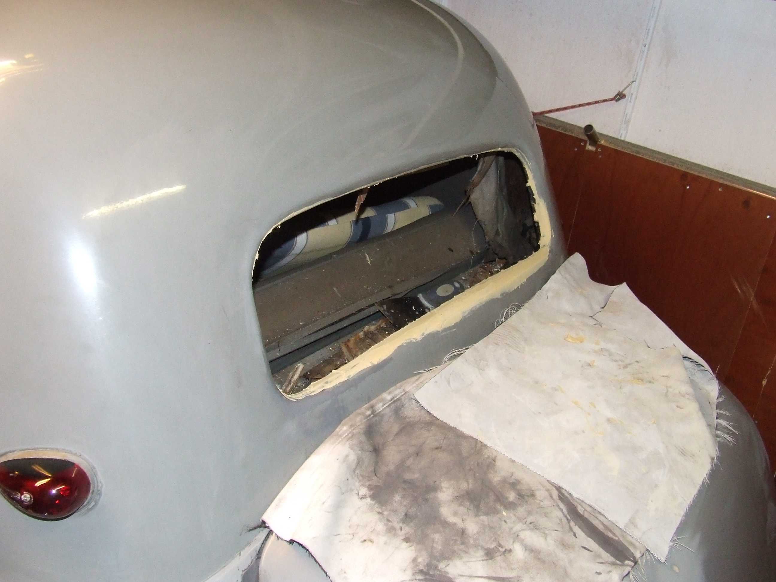
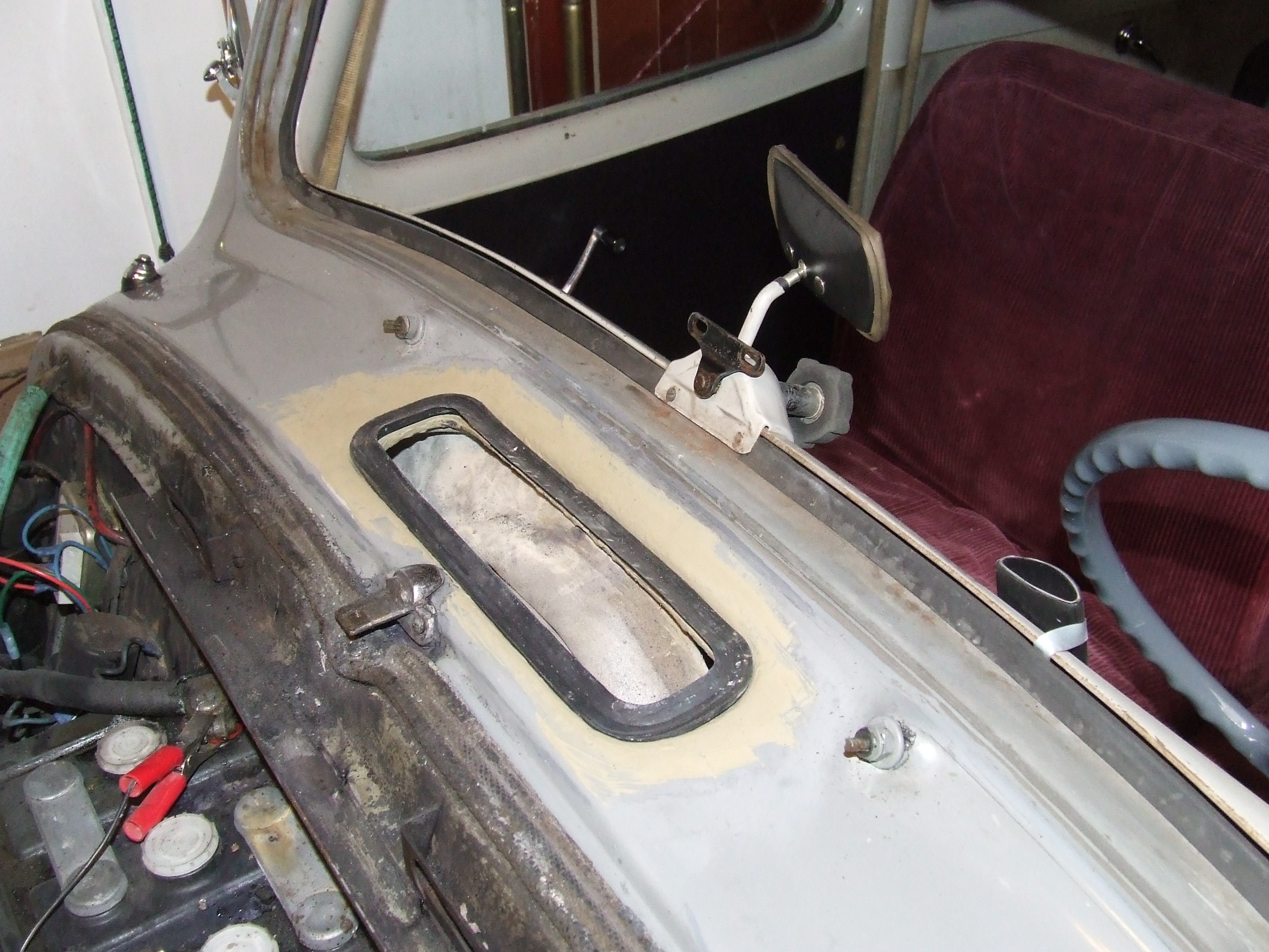
I had already noticed that the window of the right front door is only attached to the control in the door with 1 attachment point. So I had to repair that as well. The ventilation flap didn’t want to open anymore either. After careful examination I discovered that it was simply covered with lacquer. After some more careful feeling and probing I started to remove all the steel putty. Apparently this car was once taken in hand by a putty expert and then largely painted. At least this goes for the rear under the windows including the screens and the trunk on the outside.
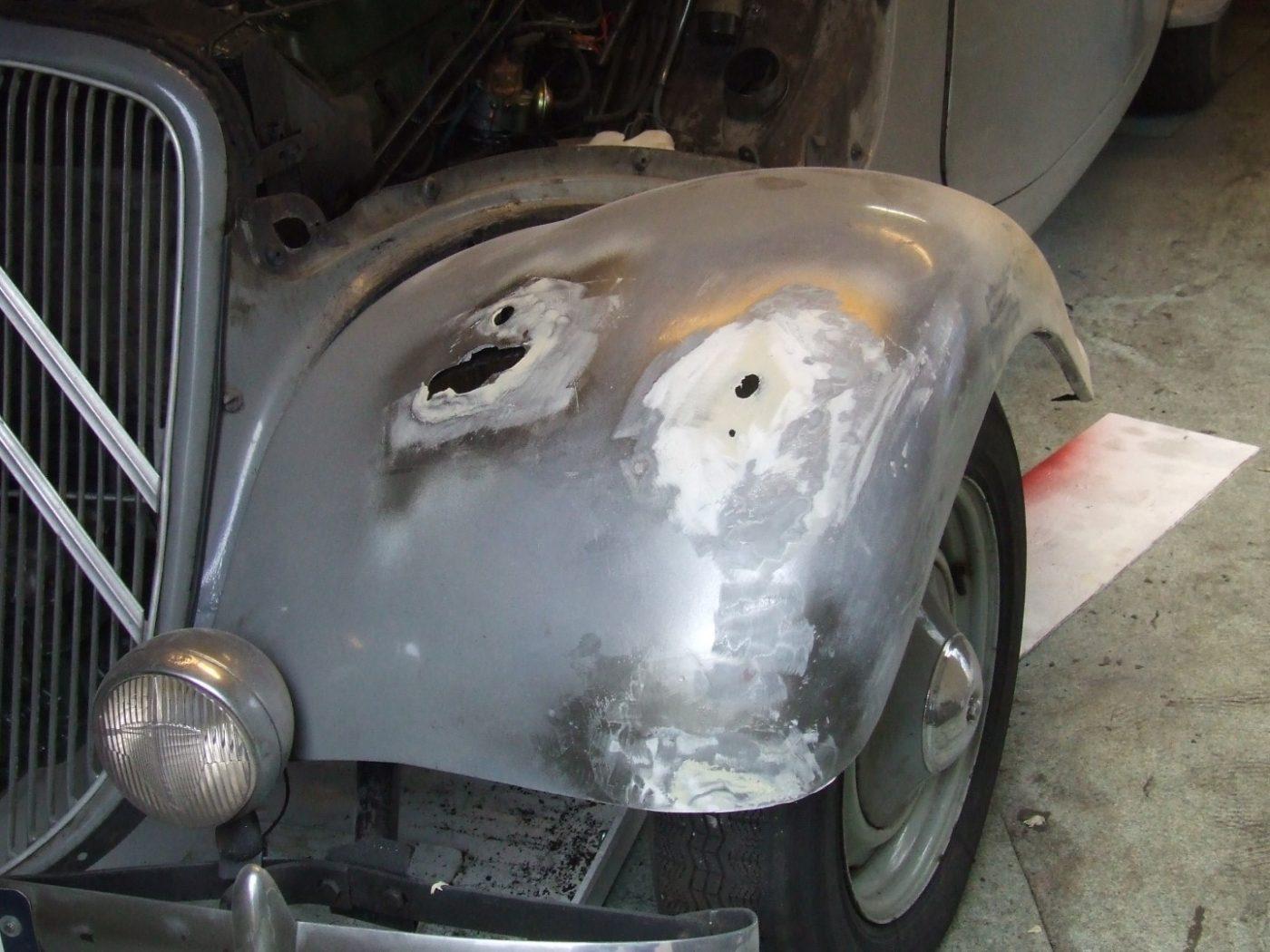
After removing the putty I was left with a body that didn’t actually have that many holes in it, and certainly no holes in the wrong places. The holes that were there, can be welded on with new sheet metal. So that is going to happen. The rear mudguards will have to be finished, because the piping between the coque and the screen has been filled and painted.
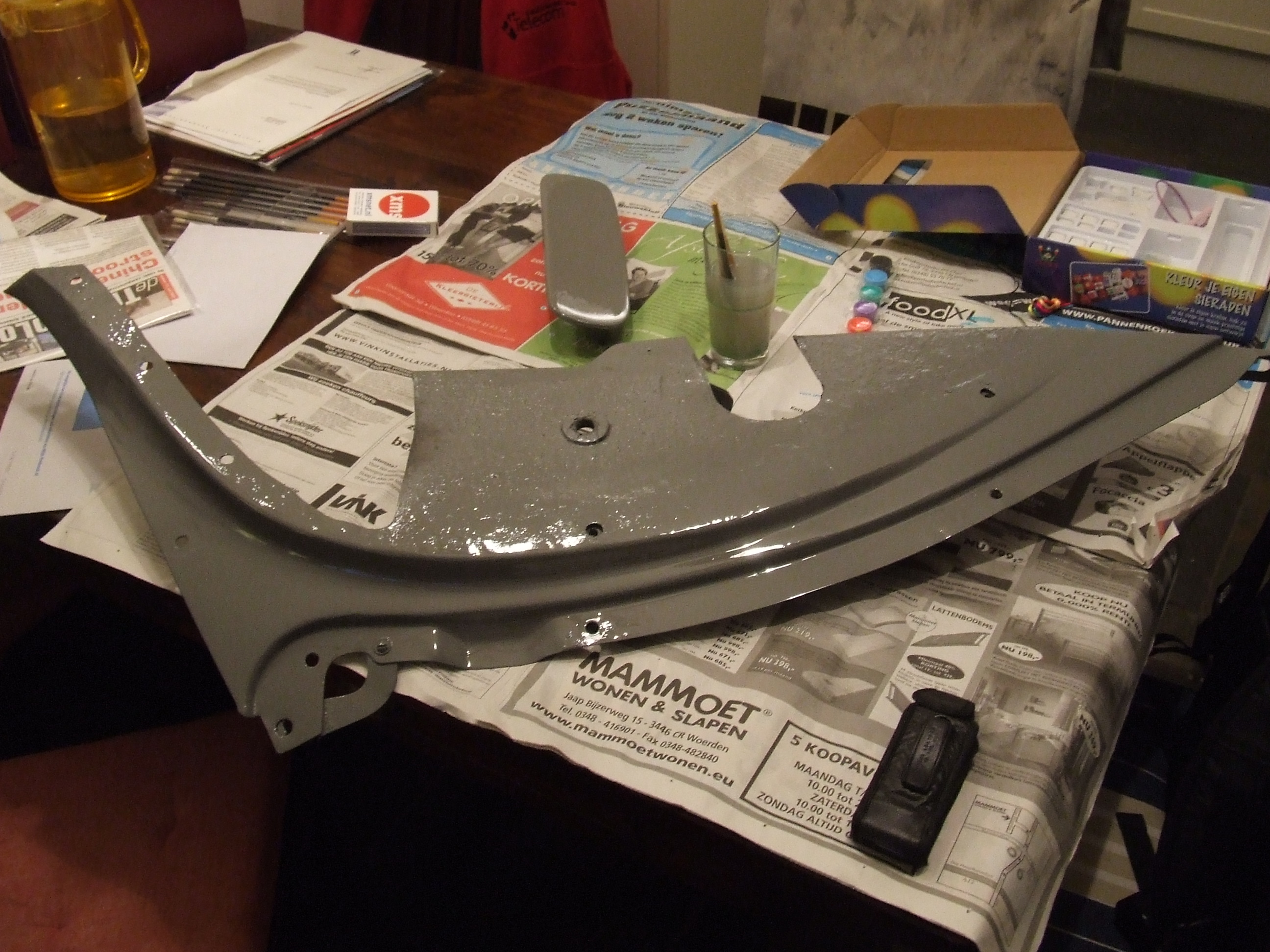
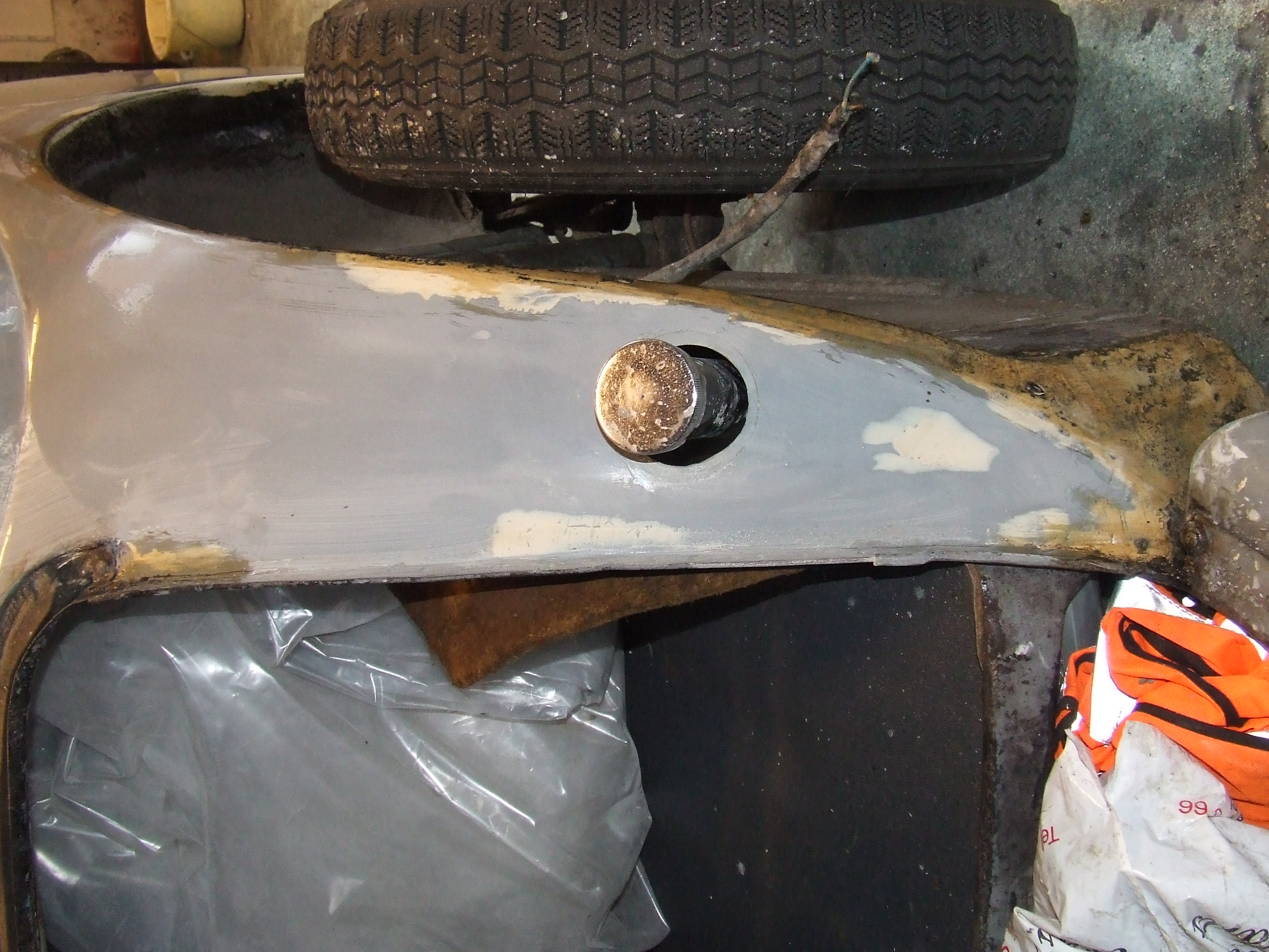
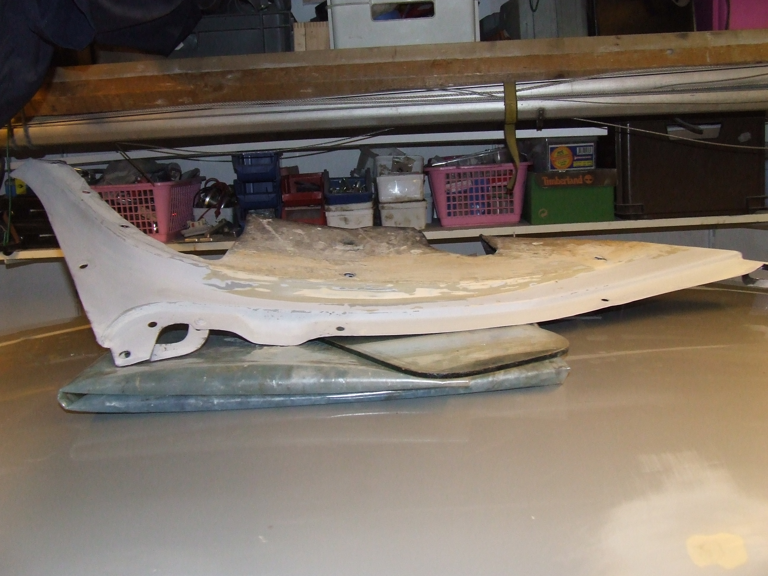
The left front fender was a setback because it had a lot of putty on it that was cracked at the bottom of the tip. After removing the decorative point and removing all the putty, a nice aluminium support under the point became visible where the putty was hanging on. Long live the do-it-yourself job! That’s going to come off as well. Order a new point, weld it on and you’re done. The shape of the entire front mudguard will be restored. Now you can push on it and the middle part just moves a good centimeter vertically up and down.
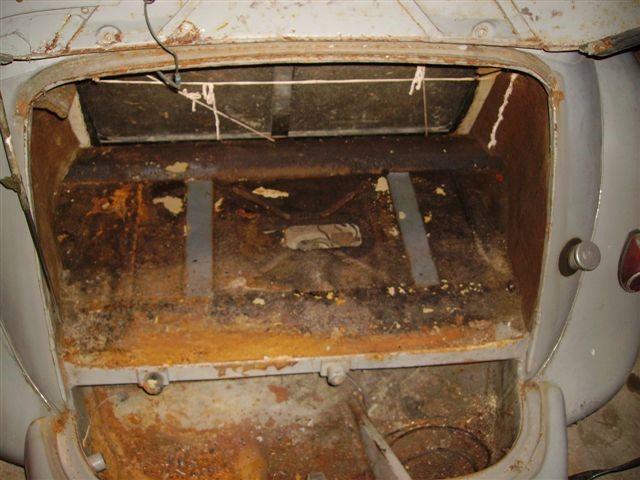
There are no holes in the trunk, but I did remove a lot of rust but all in all I just took out a quarter of a filler with my dustpan and brush.
Removed all the mess inside and dented out the first dents with the bolka hammer and counter punch. Then at least the model is back in neatly.
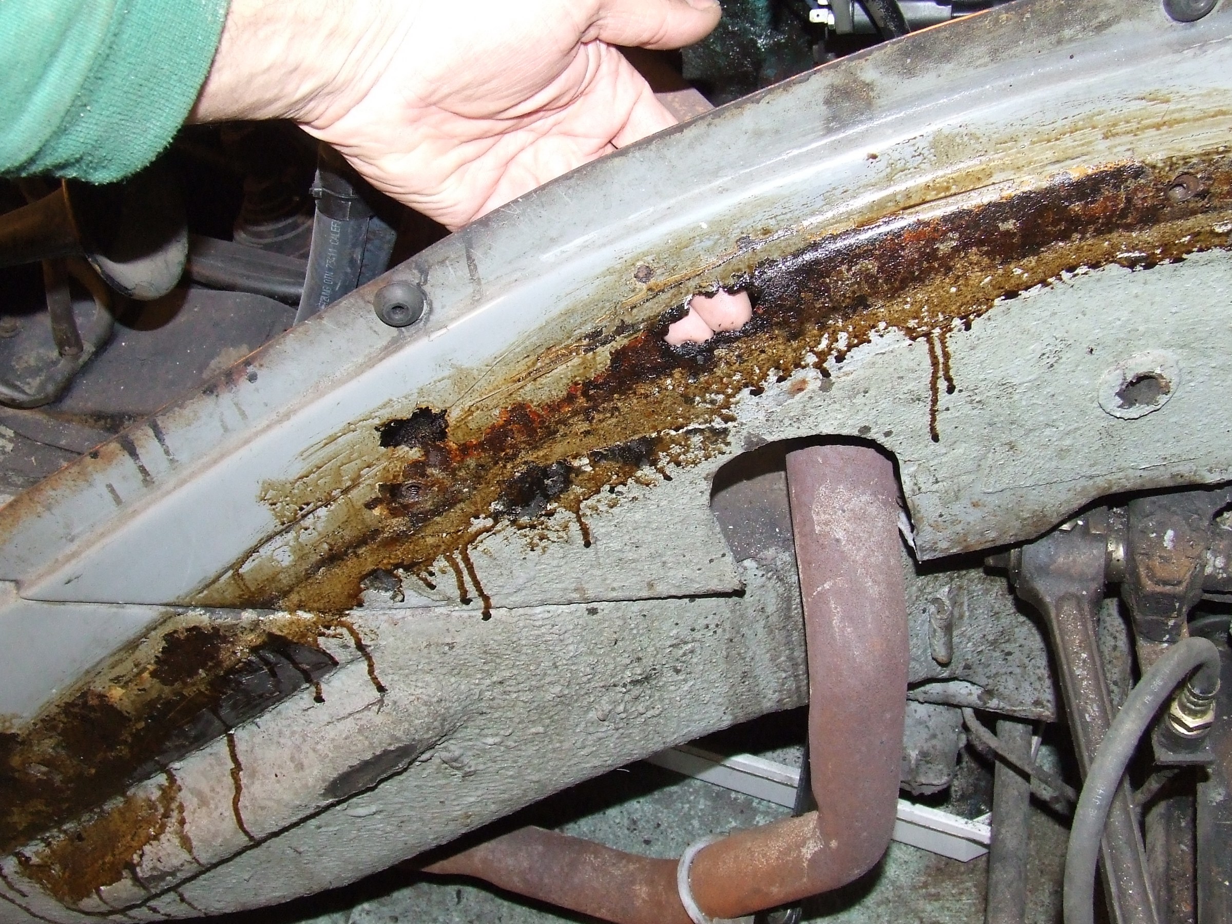
Then we have to look for a good rust converter because I have no illusions about turning it into a new car. Preservation now seems the best option for both the lower and upper parts. On the internet I saw a good preservative that you can use to treat the whole underbody by first cleaning it, de-rusting as much as possible and then applying this preservative. This will connect with the corrosion on the steel and then close it off completely. My dream was to strip the car and shovel the coque but I’ll let that go for now. First let’s see if an MOT is possible in the long run.
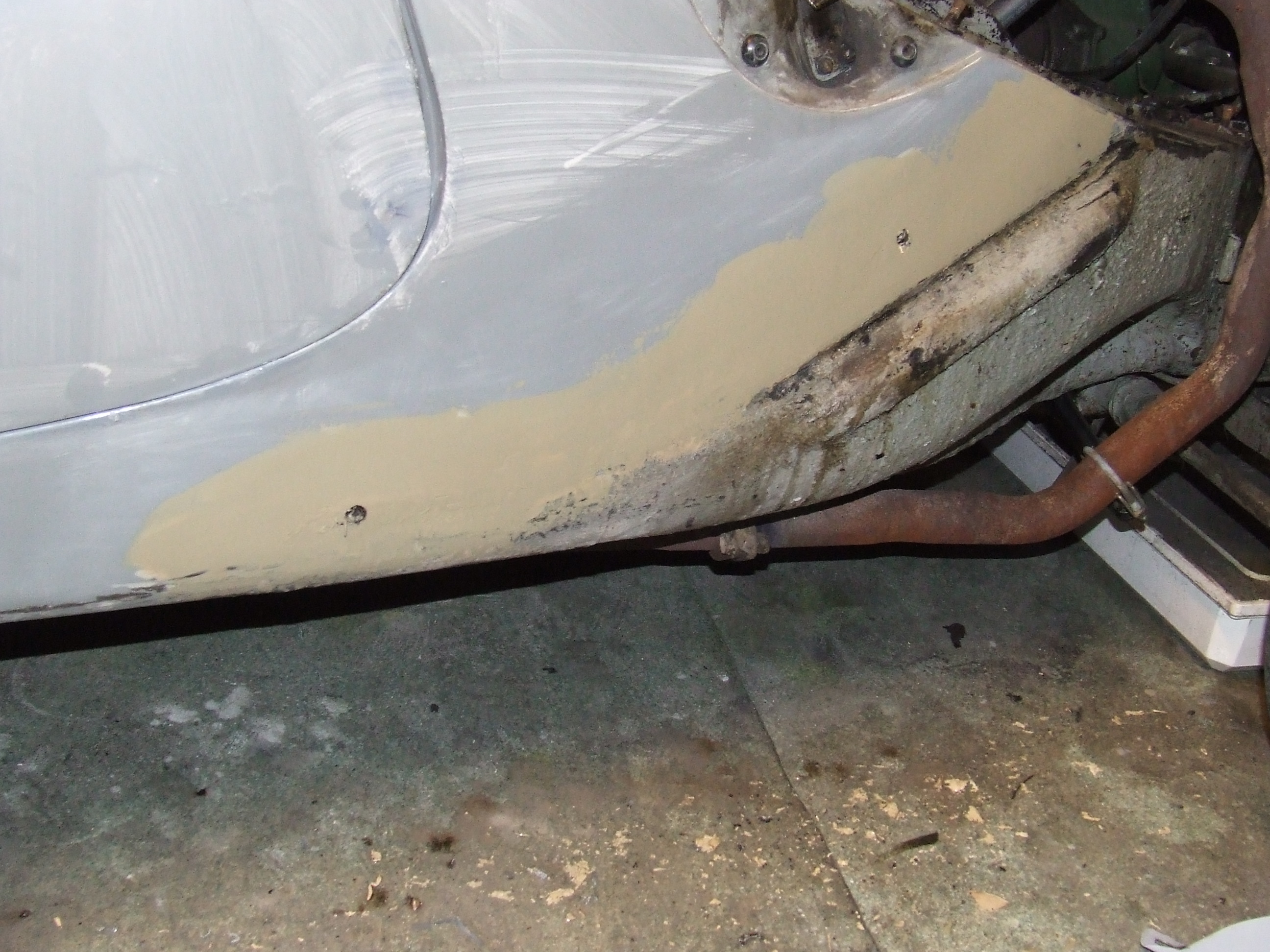
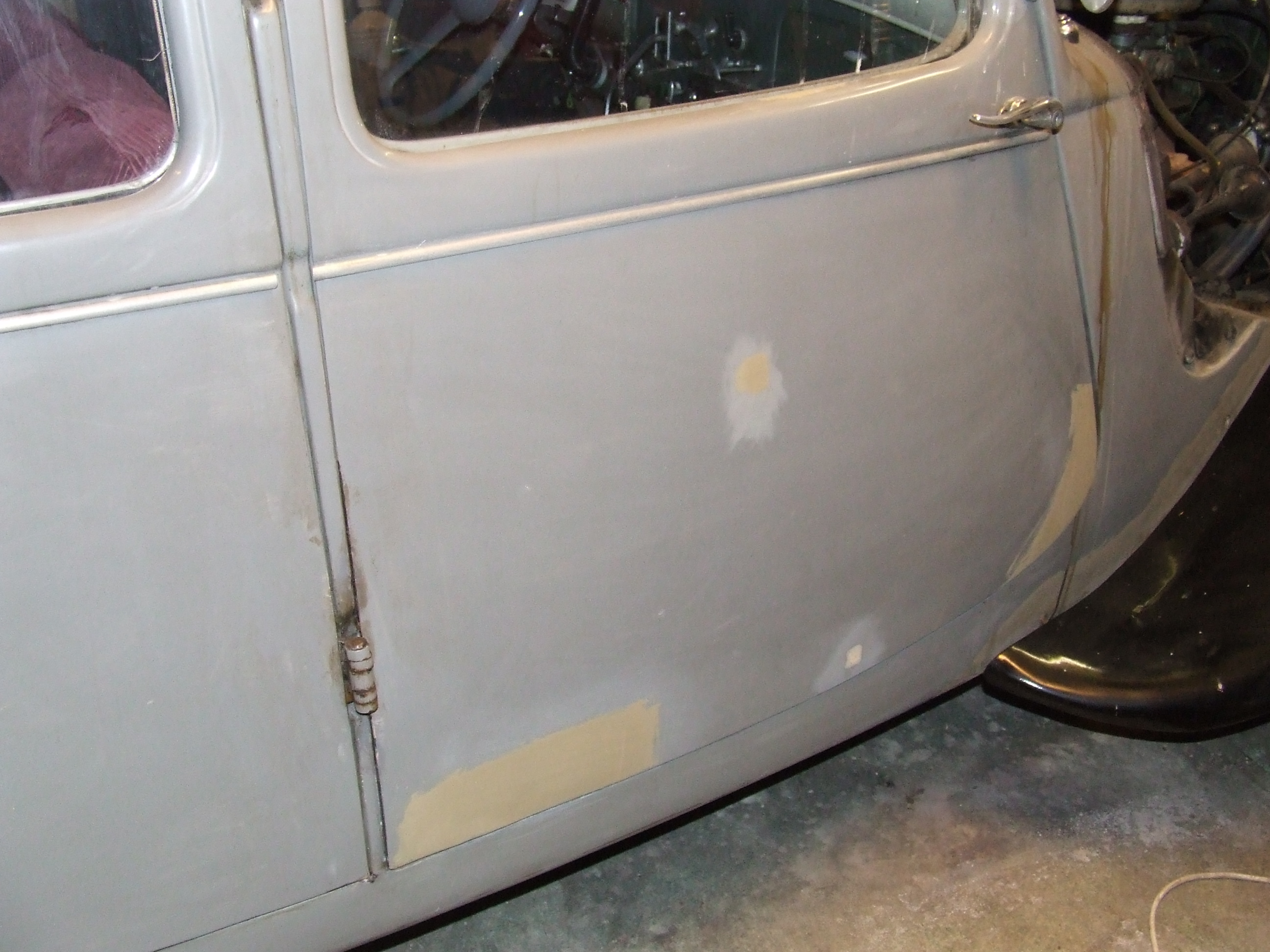
First I continued with the visible part of the exterior: I removed all the rust spots with a putty knife and brushed them with the steel brush on the drill. Then I smeared some good old fashioned Noverox on it to make sure it won’t rust for a while. On such a gray car you know immediately where you have to do some touching up because the Noverox forms a black area where it finds corrosion. So the grill, hood, part between the engine and the front wings, the front wings, doors, doorposts, gutters, rear window, trunk, rear fenders and so on were all treated and actually it was not too bad.
In the meantime, I tried to start the car with a battery to get the engine loose, but you get the idea: No result at all. I wonder if the car was put away with the engine running. Just taking a good look at the oil in the crankcase. I don’t know if you can draw any conclusions after 13 to 20 years but the oil was up to standard and looked dark and used. Not like my old Renault after a head gasket leak: completely white. Anyway, if the engine doesn’t come loose, it will have to be removed anyway. Removing the head without further dismantling makes no sense.
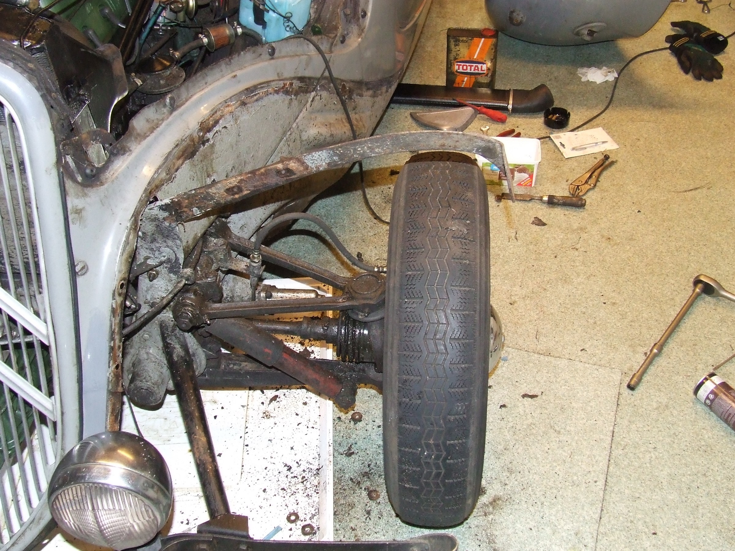
On to further inspection. Apparently the previous tinkerer had already refurbished the front train because it is completely covered in orange lead primer, the kind that is so handy but that you can no longer buy because of the environmental aspects.
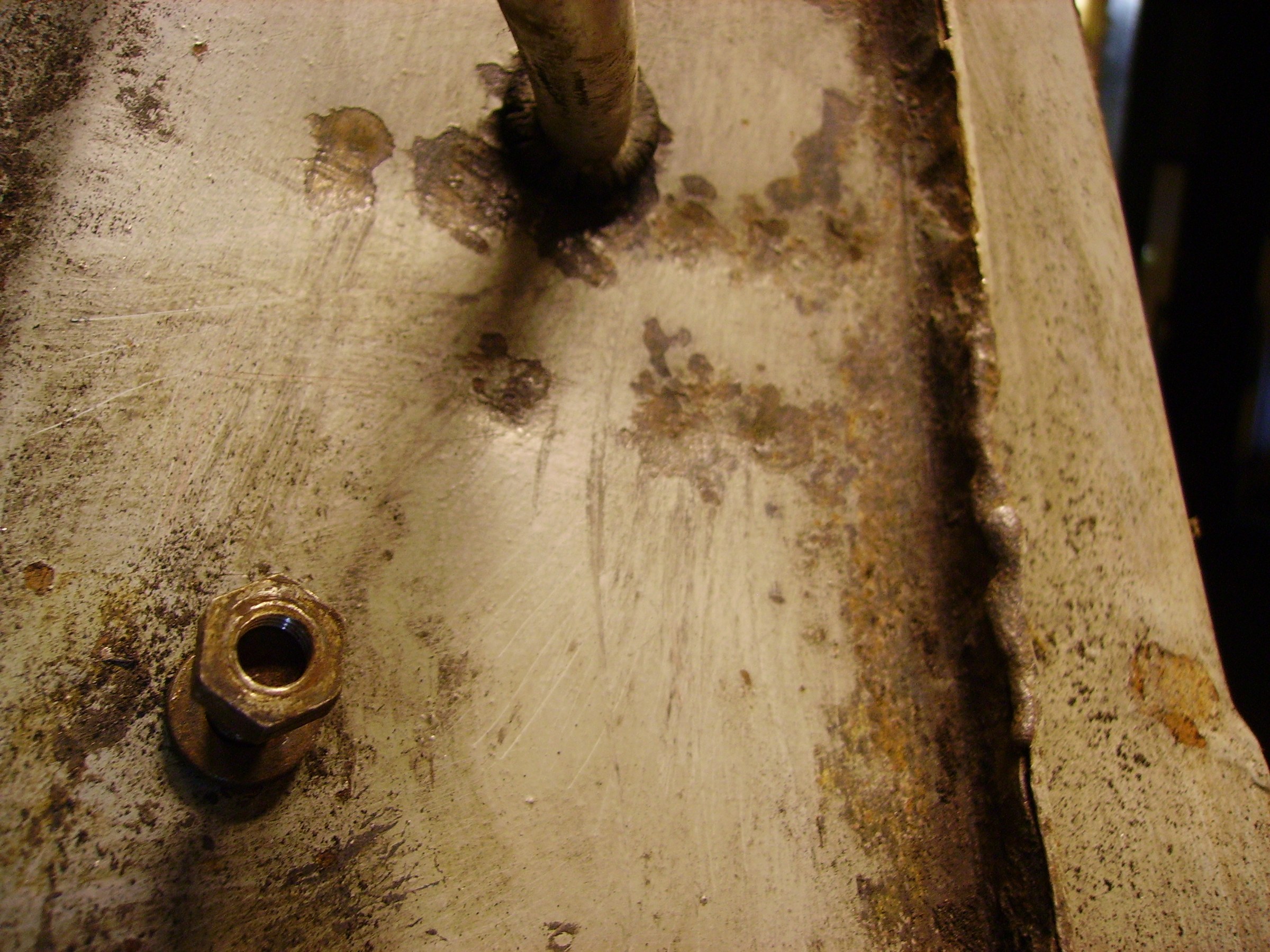
The carburettor was removed and the right 2 studs of the inlet c.q. exhaust manifold were turned completely inaccurately just inside the head. That is a nice job for the drill and the turning kit.
Turned-off studs in cylinder head
Put it in the de-ester already. Might as well remove the manifolds and put in all new studs. OK, that is how you get your chores but good. If the engine has to be removed the manifolds have to come off anyway. Maybe replace the valve seats for harder ones because of the unleaded petrol.
Then on to the inspection tour: All the original things you wouldn’t expect from a tinker car are still there, such as an original 2 liter oil can including bracket and spring on the inside of the left hood.
Then let’s just fill and charge the 6 Volt battery. Sure enough, there is still a tiny bit of life in it. Enough for the horns and lights. But the clignoteur doesn’t work or is just not there.
Still need to check the chassis and coil number to see what the actual year and month of manufacture is. Can I see what type of engine and so on is actually in it.
A nice detail is that the radiator is renewed, at least the inner part and that the original operation of the roller shutter for the radiator still works flawlessly. After the necessary de-rustering and careful adjustment of the shutter, it worked perfectly as it was originally intended.
Went to the parts store and they still had original brake fluid for TA and ID/DS early years. It was a very old bottle but I bought it anyway. Price was still in guilders with old VAT rate but with what’s to come I can use an old price!
As long as the engine is still soaking with the de-ester I will continue my expedition to restore everything I find as original as possible. Go ahead and start on the brakes first.

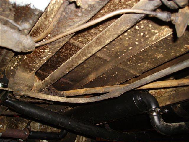
Another inspection trip under the car and it just looks really tight. I removed layers of black gunk in all the right places with my awl and putty knife, but steel came out cleanly everywhere. It looks as if a whole new bottom plate was put in at one time or that the car has been maintained very well in this aspect. In any case, it is a boost that I needed for I am not making much progress with only negative reports.
By the way, I still have to order new license plates, at least one because in the front there is one where the plastic letters have mostly disappeared. And oh yes, my registration certificate part 1 is almost torn and part of the paper has perished. I don’t know what text I’m missing but the serial number and such is still on it. I will send an application to the RDW asap for replacement of part 1. Fortunately you don’t really need it for the registration, at least not at that second office of post offices where I was.
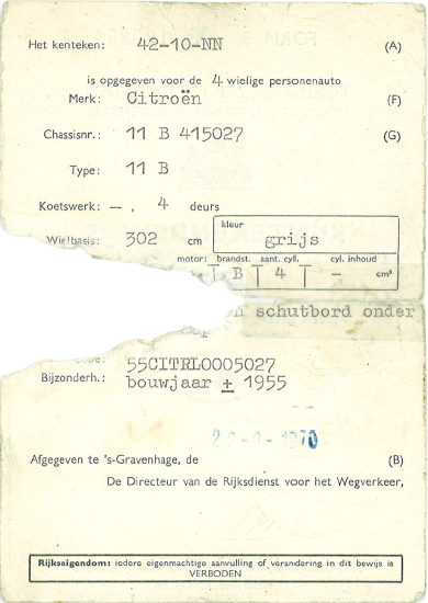
Original license paper (from 1970, import date into NL) part 1
In any case, I will cover the door panels because it really doesn’t look like it with those holes in it.
Then I can also take care of the window mechanisms. I still have to figure out how to remove the door handle and window crank but I have one of those handy workshop manuals that doesn’t say just that. Then I’ll just have to see what the trick is: A hidden spring or just pulling hard….
30-7-2006
Sunday, time for reflections….
Removed the rocker shaft last week, you never know….
The engine is still stuck.
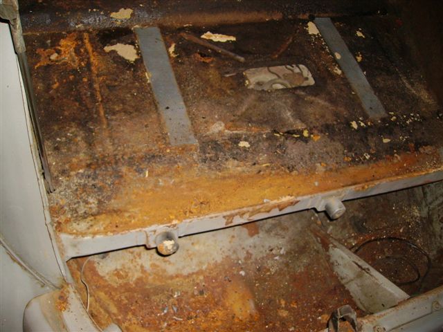
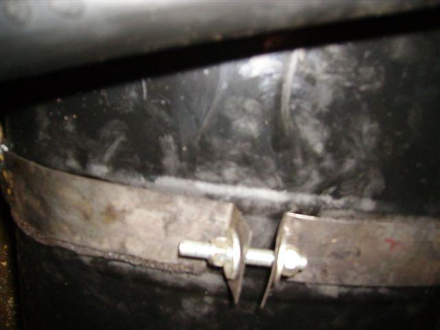
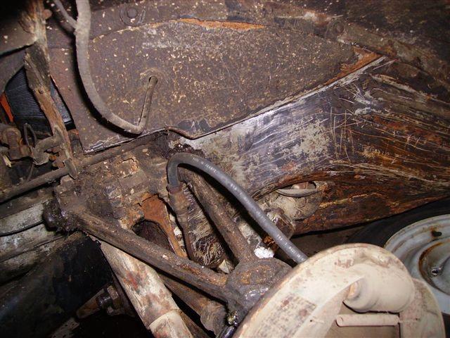
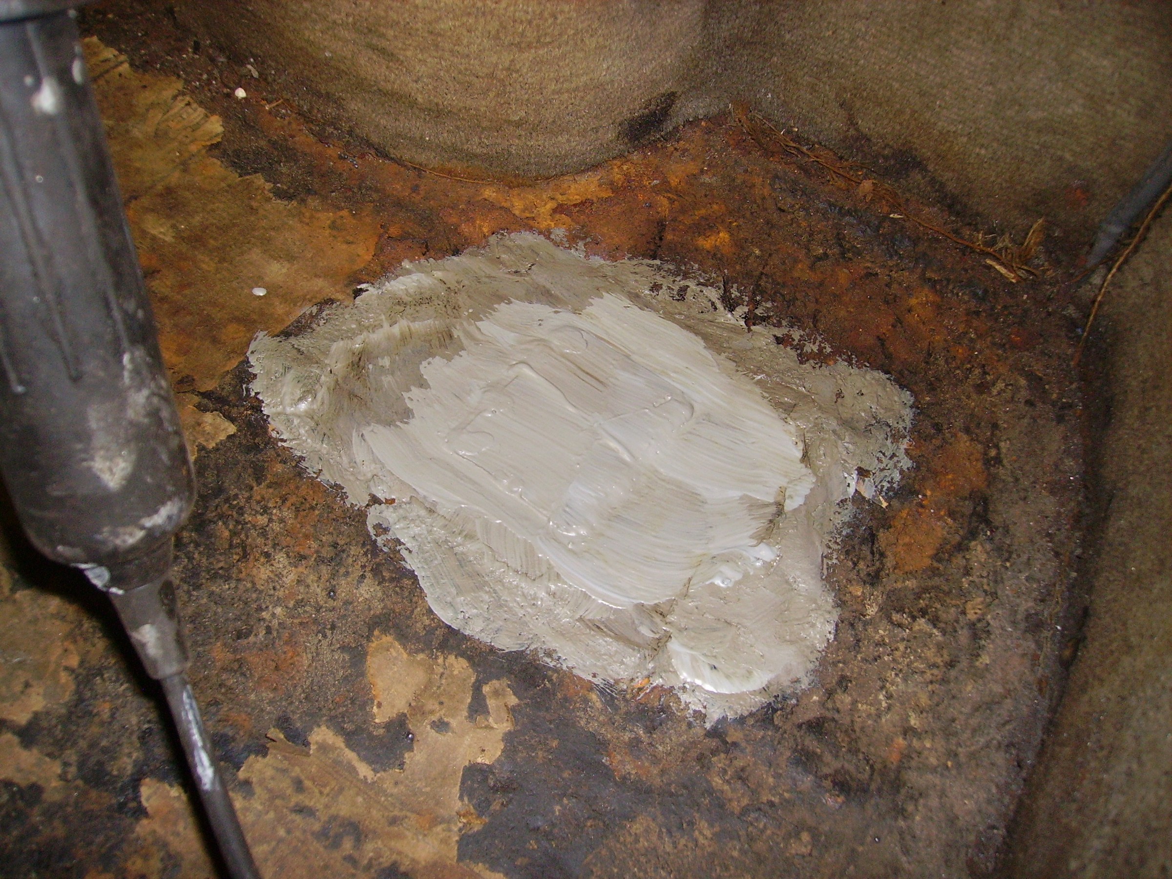
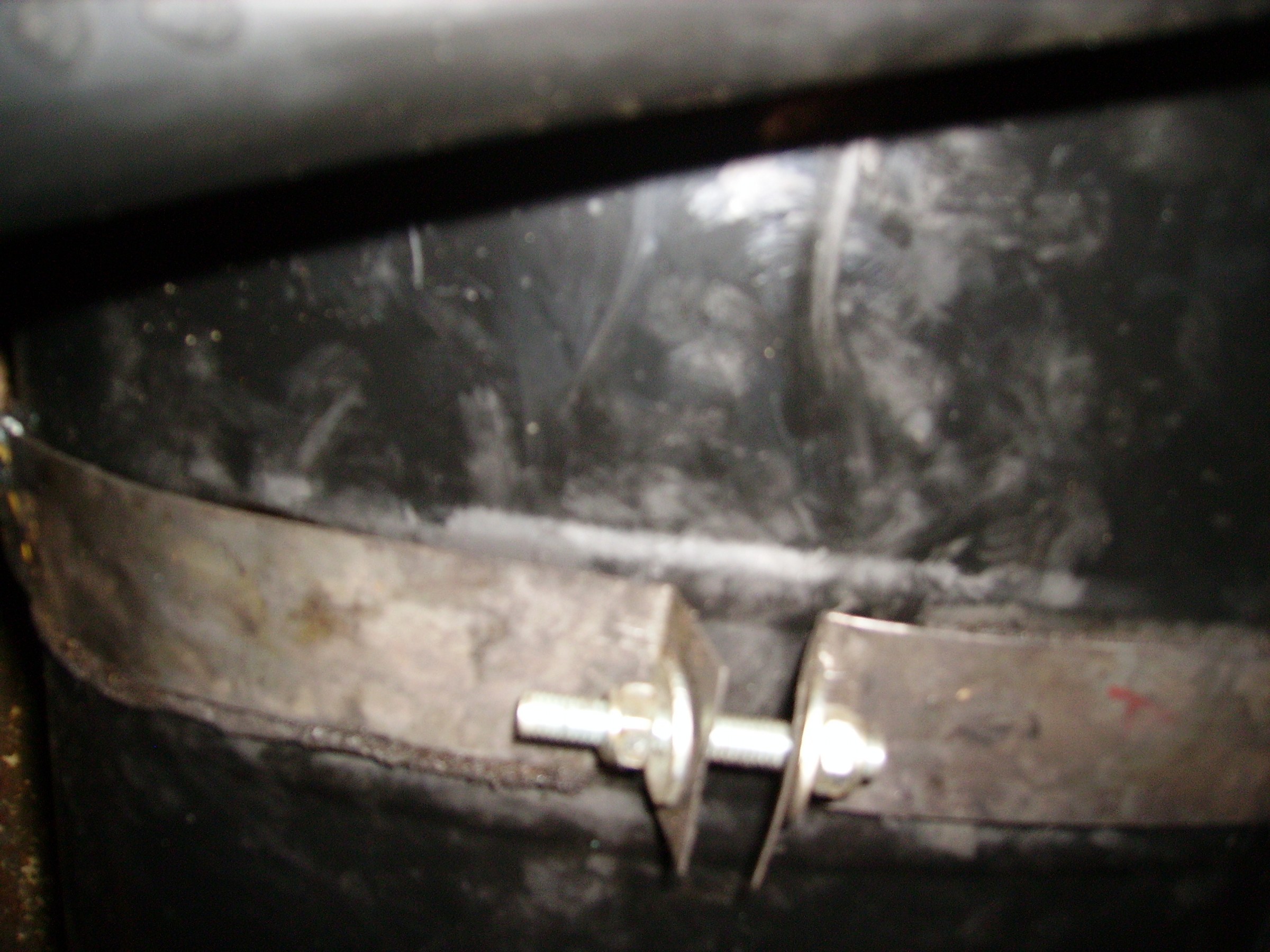
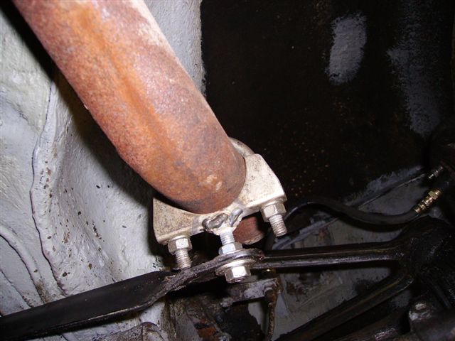
I did replace the rear brakes from steel to copper, at least where it was bad. In the end it only turned out to be the pipe from the left rear wheel to the right rear wheel. It is attached to the rear axle with 3 clamps. Of course it started leaking under the middle clamp, in the middle of the rear axle.
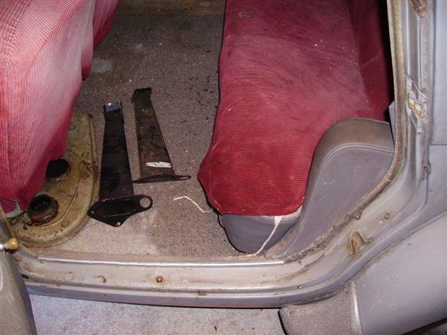
Overall condition of the rear floor is okay, except for the left sling of the petrol tank, which is secured with rope. So also put it on the wish list.
The new setup to get the engine loose is now as follows:
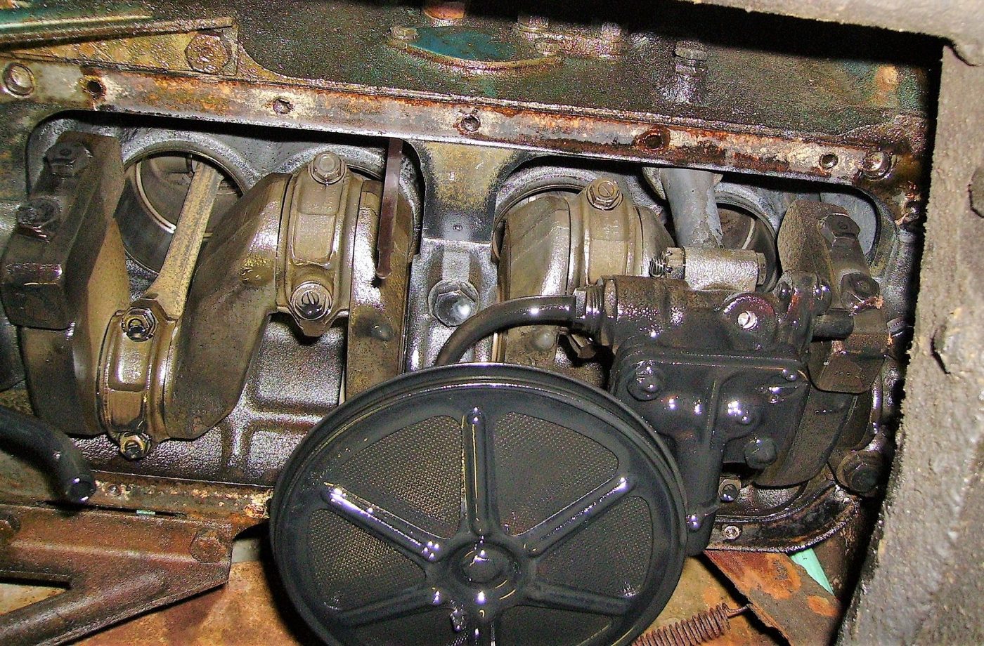
Take out the crankcase while the engine is still in it. That means a lot of bucking under the front of the car, draining and especially overalls and gloves.
If the pan can be removed, it is important to loosen the connecting rods one by one (first remove the oil pump?) and to make the pistons movable. If that is successful and the bearing shells c.q. inside connecting rod and crankshaft are OK, then reassemble and make the rest rotatable.
I have the time so it should be possible, provided the sump pan can indeed be taken out while the engine is still in the car.
Am reluctant to take the head off. On inspection, the water level was still above the cylinder head, so I assume that the head gasket is not leaking and I should therefore stay away from the head.
If it is not possible to get the pistons loose with the engine in the car, there is still the option to remove the head and the pistons including the connecting rods and wet bushings. First make a good mark of course but the condition remains that the carterpan has to come off with the engine still mounted in the car.
Meanwhile, removed the upholstery from the front doors. The front right door had a lot of rust in it AND the window mechanism is broken. Needs a new rail in at the bottom of the window. The rest is still OK. Wondering if such a rail can be bought separately. It looks like a clamping rail around the steel edge at the bottom of the window. So also on the wish list.
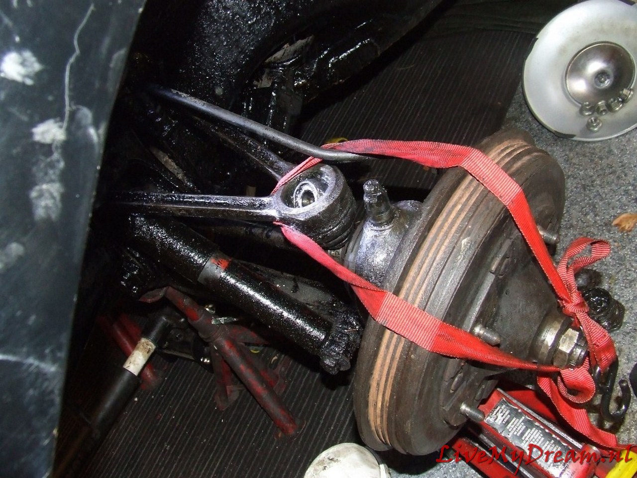
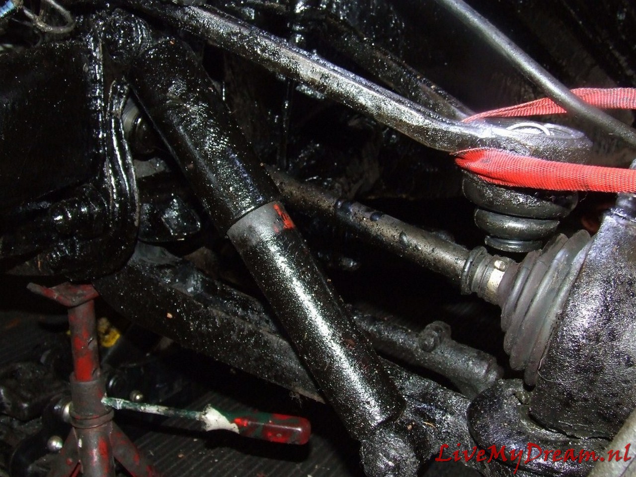
Last week I also mounted the bumper brackets and the bumper. Wrench cap 41 and hang on to those coquem nuts. Took two hours to get both completely loose. Good stuff that rust remover. In the meantime I removed all the gunk from the triangles and other parts that go to the front wheels. In the process I found about 12 lubrication points which I immediately lubricated. I was surprised that I didn’t need to put a lot in to see the gunk coming out already. That is a good sign because there was still compound in the steering knuckles and bushes.
Did other things for a week. Thought about how to proceed.
Removed the crankcase.

Carterpan eraf
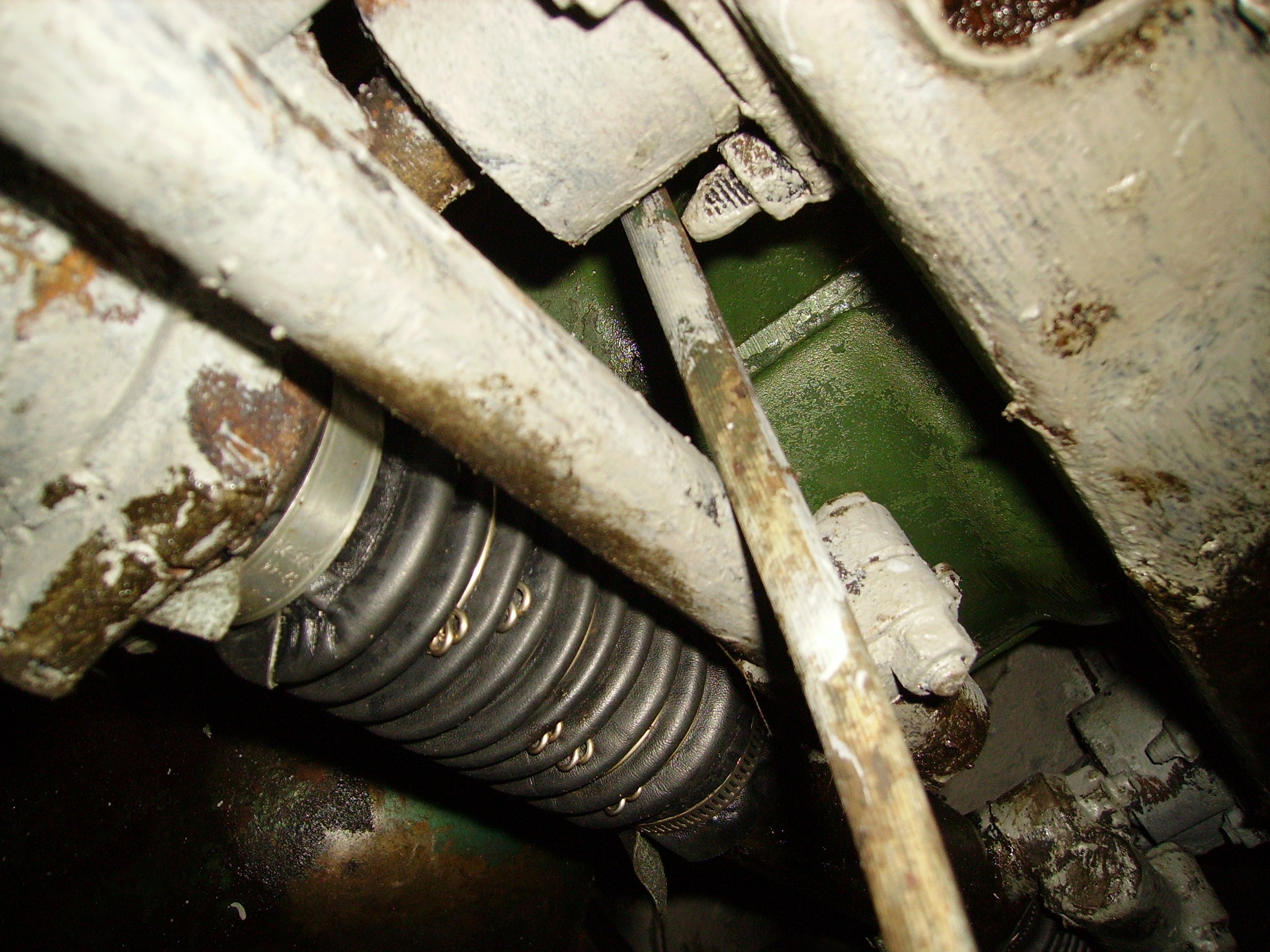
Goed gekeken aan de onderkant in de cilinderbussen. Bij de voorste 3 cilinders was de losmaakvloeistof langs de zuigers gelopen, de achterste was helemaal droog.
Onder-binnenzijde 3e cilincer die lekker olie-achtig was
De onder- binnenzijde 4e cilinder zat nu nog muurvast
Drijfstang van achterste zuiger losgemaakt, met de bouten nog in de drijfstang. De krukas beweegt als er druk op wordt uitgeoefend. De eerste 3 zuigers zitten dus los.
Drijfstang achterste zuiger weer vastgemaakt.
Water eruit laten lopen via aftapplug in zijkant blok.
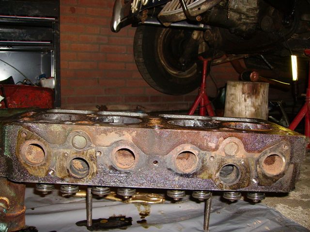
Tuimelaaras was al verwijderd, de kop eraf gehaald inclusief waterpomp.
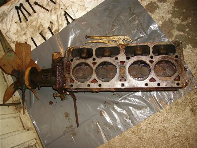
Gedemonteerde cilinderkop incl. waterpomp
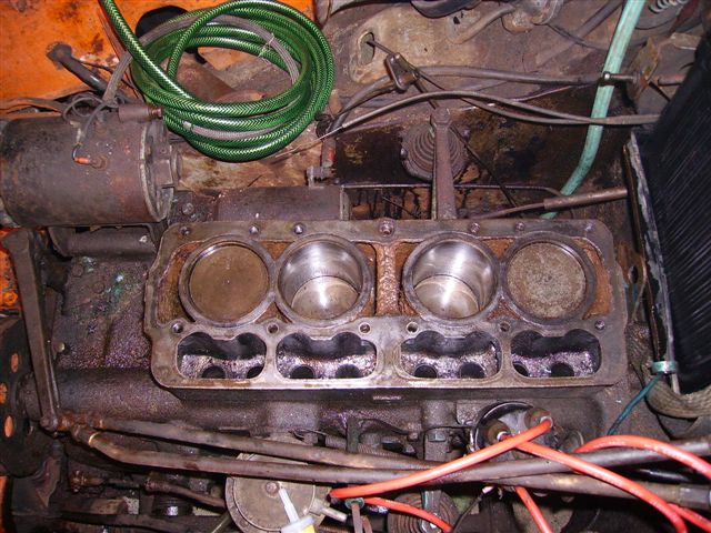
Cilinders en zuigers NA de losmaakoperatie, vlak voor het monteren van de nieuwe cilinderkop
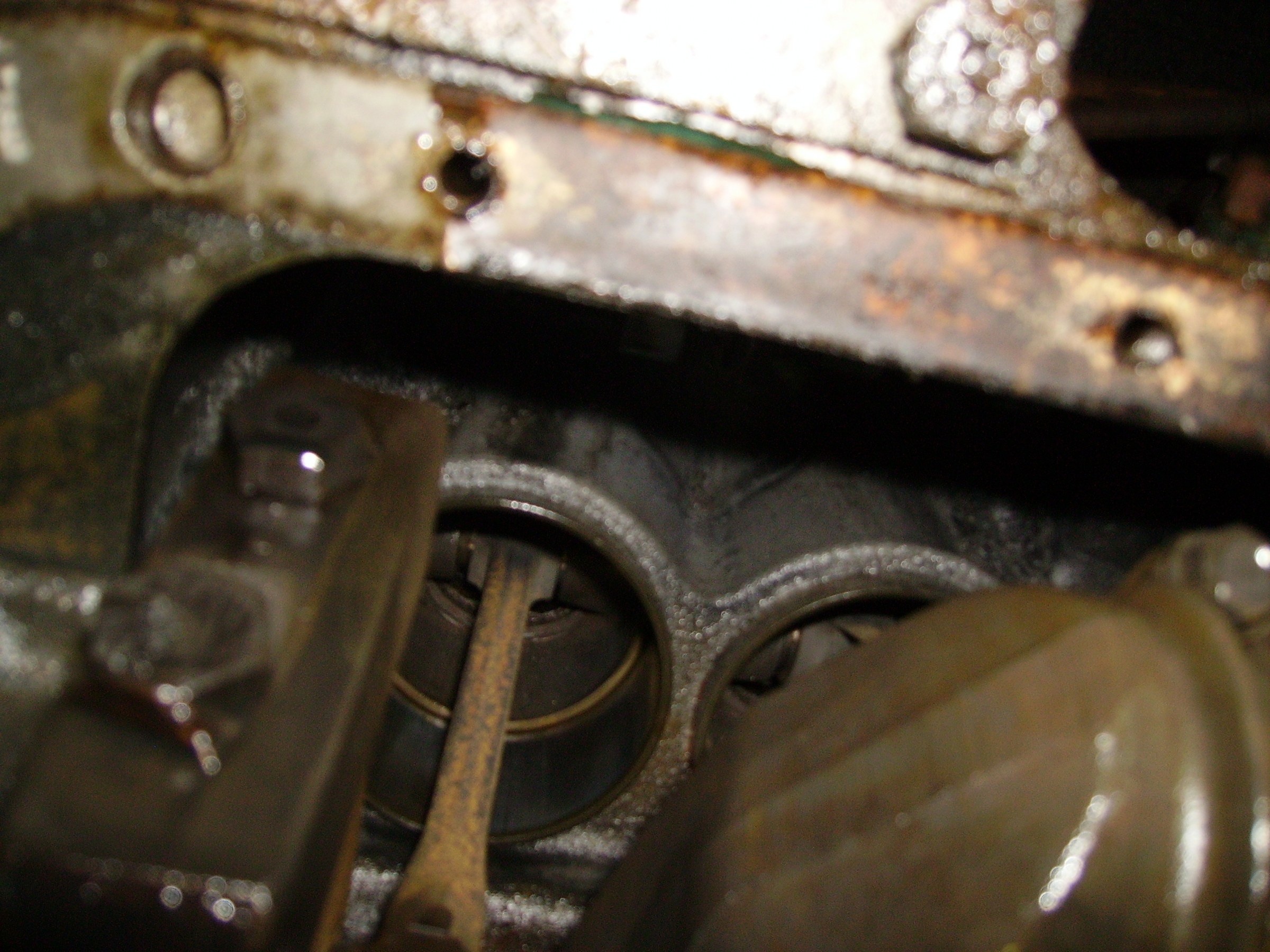
En jawel, de oorzaak van alle ellende: Lekke koppakking in het uiterste rechterhoekje (vanaf de bestuurder gezien) bij de achterste (4e) cilinder.
Dus roest in deze cilinder maar gelukkig staat de zuiger bijna onderin.
Schoonmaken maar en schade bekijken.
Cilinderwand iets geroest maar geen putjes of inroesting. Met 400 waterproof schuurpapier heeeel zachtjes de roest verwijderd. Weer alles schoongemaakt.
Natte bussen geborgd met ringen en bouten zodat ze niet per ongeluk loskomen als de zuigers bewegen.
Onderkant van de cilinders ingespoten met roestoplosser.
Met een blokje zacht rondhout en een koperen vuistje heeel voorzichtig de 4e zuiger naar beneden getikt. Olie op de zuigers gedaan.
Vanaf onderzijde vervolgens de zuiger met een blokje zacht hout heeeel zachtjes met koperen vuistje de 4e zuiger naar boven getikt. Deze actie een paar keer herhaald waarbij al na de 1e keer alles merkbaar soepeler ging.
Vervolgens via de startslinger gedraaid tot alles soepel liep.
Na een goede schoonmaakbeurt van de zuiger-bovenzijdes, de cilinderkop, kleppen en het reinigen van het blok en kop waar de pakking moet komen, nieuwe koppakking met olie besmeurd en gemonteerd, kop erop en gemonteerd.
Tuimelaaras gemonteerd, stoterstangen gemonteerd, kleppen koud gesteld op 0,4 mm.
Nieuwe carterpan-pakkingen gemonteerd. Carterpan er weer op.
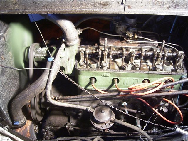
Spruitstuk er weer op, dat moest er af want de vorige sleutelaar had 3 tapeinden afgebroken. Dus allemaal nieuwe tapeinden erin en weer gemonteerd. Carburateur erop, benzineleiding erop.
De waterpomp had ik aan de kop laten zitten, dus dat zat gelijk goed.
Ontsteking gesteld, bougies erin, water in het koelsysteem.
Accu gekocht, 6 Volt natuurlijk, en aangesloten.
En.. starten maar.
Maar alleen maar plofjes en helemaal geen mooi ronkend motorgeluid.
Nou ja, even nadenken maar… Hoe zat het ook al weer, je hebt carburatie nodig, ontsteking en.. compressie! De eerste 2 werkten. Dan de compressie maar meten.. En jawel, bij cilinder 1 gelijk al een probleem met compressie van 1 bar. Daar loopt zo’n motor natuurlijk nooit mee. De 2e was iets beter en nummer 3 en 4 beiden 3 bar.
Dan maar even olie erop (de zuigers dus) en opnieuw meten. Geen verbetering.
Dat betekent een probleem met de cilinderkop. Kop eraf halen, gelukkig weet ik nu hoe dat moet.
Kop helemaal kaal gemaakt, alle uitstekende delen eraf en achterin de auto gelegd.
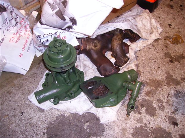
Waterpomp (2 weer mooi groen gespoten delen) en spruitstuk
Bij CTA een revisiekop gekocht, kan ik gelijk gewoon op loodvrije benzine rijden.
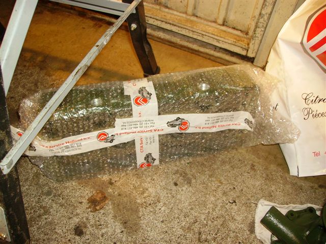
Nog in plastic verpakte revisie-cilinderkop
Kop thuis met nieuwe pakking gemonteerd (en waterpomp, spruitstuk, tuimelaaras, stoterstangen, kleppen stellen, carburateur, enz…, scheutje benzine in het carburateurgat gegoten) en… in 1 keer starten!
Bewegende beelden!
Benzinepomp aangesloten, benzine in de tank, filter ertussen, starten en… lopen!
Carburateur bijgeregeld op stationair toerental. Loopt fantastisch stabiel langzaam rond.
Uurtje laten lopen en laten afkoelen. Bougies verwijderd en compressie gemeten. Elke cilinder tussen 6 en 6,5 Bar. Daar doe ik dus even niets meer aan.
Verlichting
Alle lampen gecontroleerd en waar nodig vervangen, clignoteur gemonteerd.
Eerste proefrit
Op zondagmorgen was het zover: Lekker rustig op de weg dus maar eens proberen hoe het gaat. Inmiddels de wagen verzekerd want dat is wel zo handig als ie naar de APK gaat zometeen.
Rijden gaat wel, de koppeling hapt wel heel erg. Schakeling gaat wel goed als je maar heel langzaam doet. In z’n 1 of achteruit gaat moeilijk dus ontkoppelen gaat niet helemaal vlekkeloos.
De tweede versnelling maakt een vreemd bijgeluid.
Remmen is gewoon eng: Naast de verschillende geluiden trekt de auto geheel naar links. Zal rechts wel vastzitten.
Bij terugkomst besloten om het volgende eerst te doen: Remmen, versnellingsbak/tandwielen inspecteren, koppelingsplaten vervangen en alles goed schoon- en vetvrij maken qua koppeling.
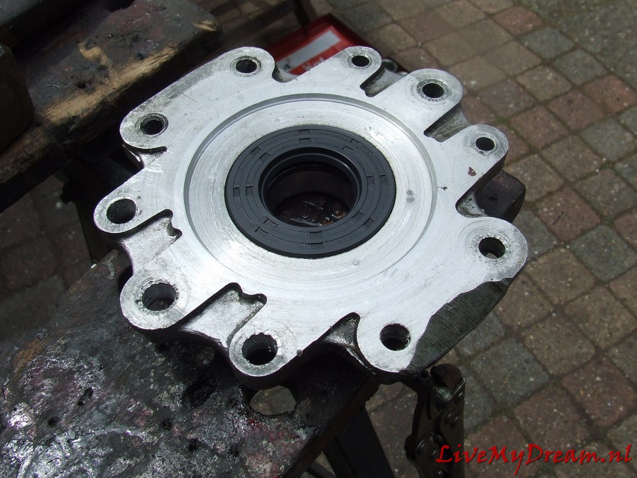
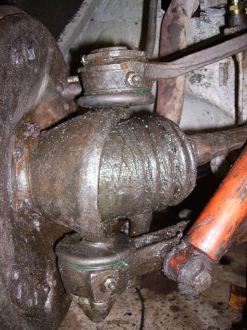
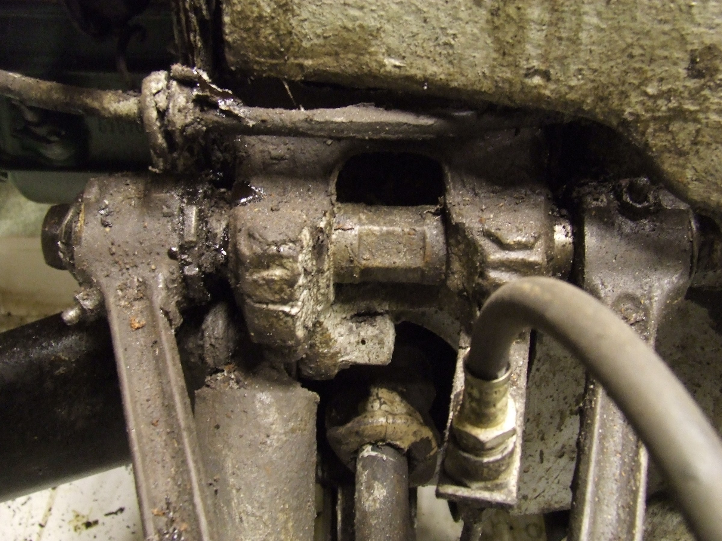
Daarnaast de oliekeringen van het differentieel bij de diff assen vervangen.
Bij inspectie bleken de moeren van de korte assen bij het differentieel los te zitten. Oeps, gelukkig maar een korte proefrit gemaakt….
Remmen
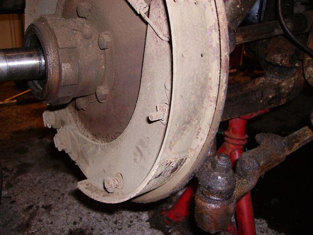
Wielnaaftrekker gekocht want met mijn universele trekkers lukt het echt niet.
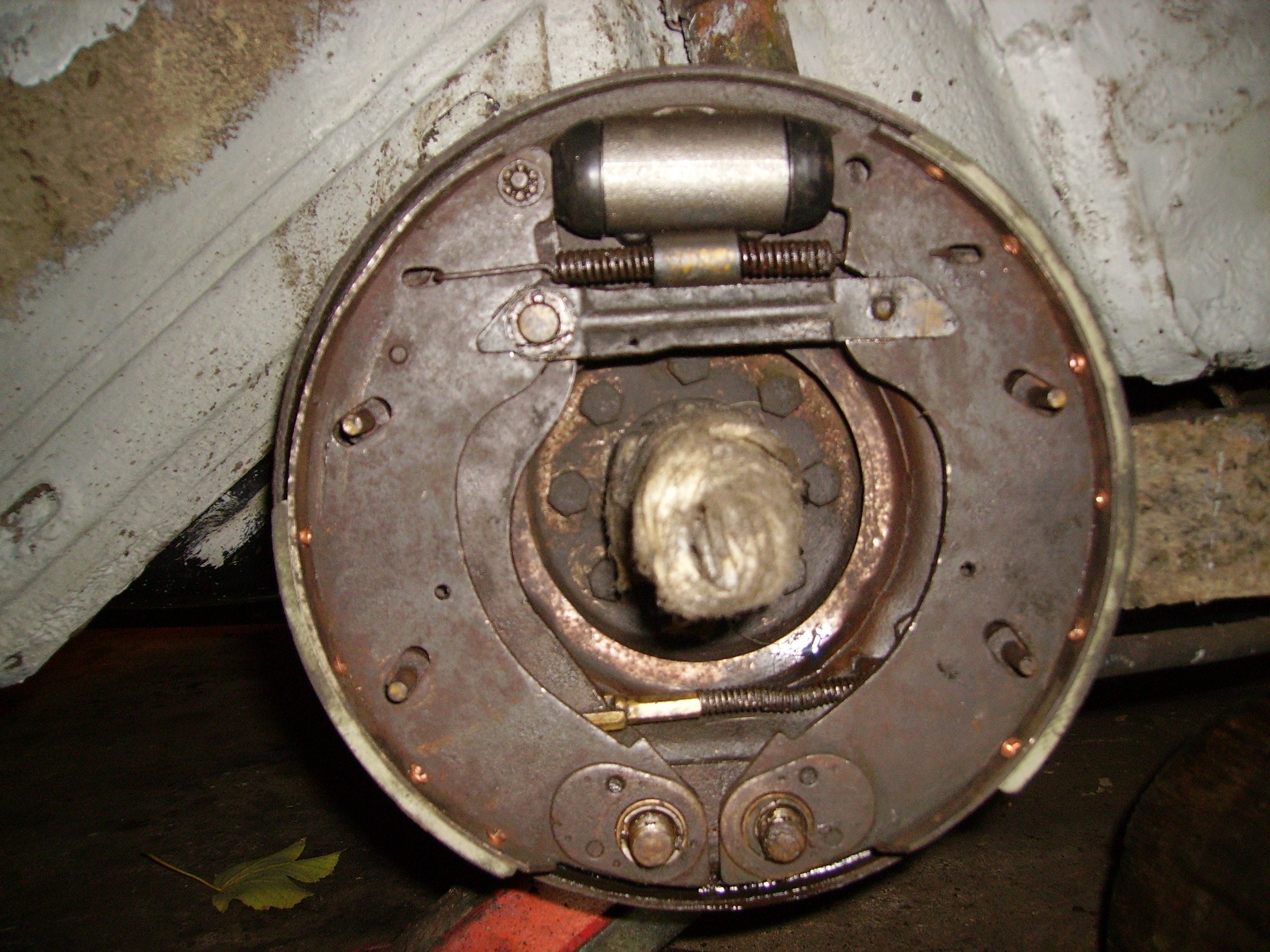
Voorste wielremcilinders afgenomen, leeggehaald en goed bekeken en bevoeld. Zijn van binnen helemaal hard. Geen putjes of iets dergelijks. Nieuwe cups en stofkapjes gemonteerd. Leidingen zijn OK. Nieuwe voeringen gemonteerd.
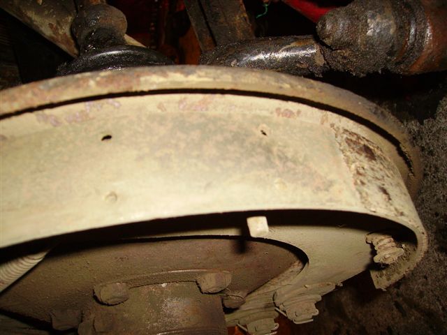
Voering van linkervoorwiel grotendeels gewoon verdwenen; rest versleten tot halverwege de koperen klinknagels
Voering erg dun geworden
Proefrit gemaakt. Halverwege steeds meer herrie wanneer de bak in 2 staat. Verder alleen in 1 en 3 gereden en snel naar huis gegaan. Remmen doen het goed. Moet achterwielen qua remmen nog doen.
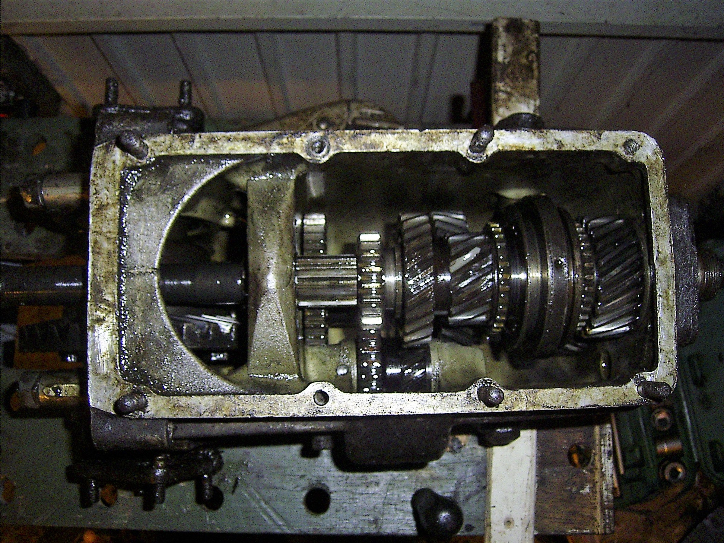
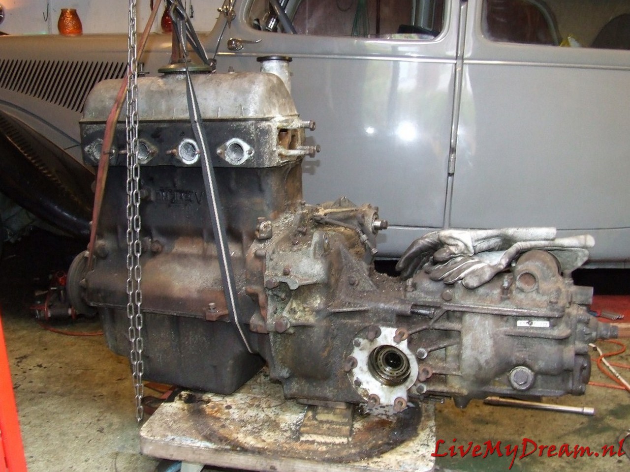
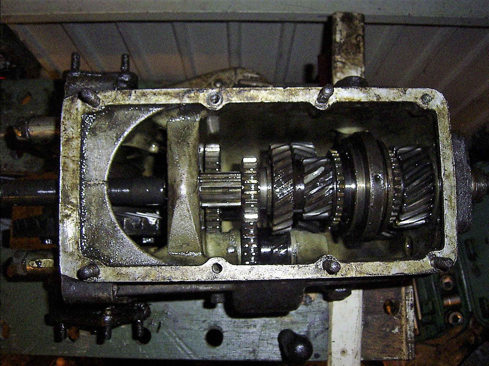
Versnellingsbak
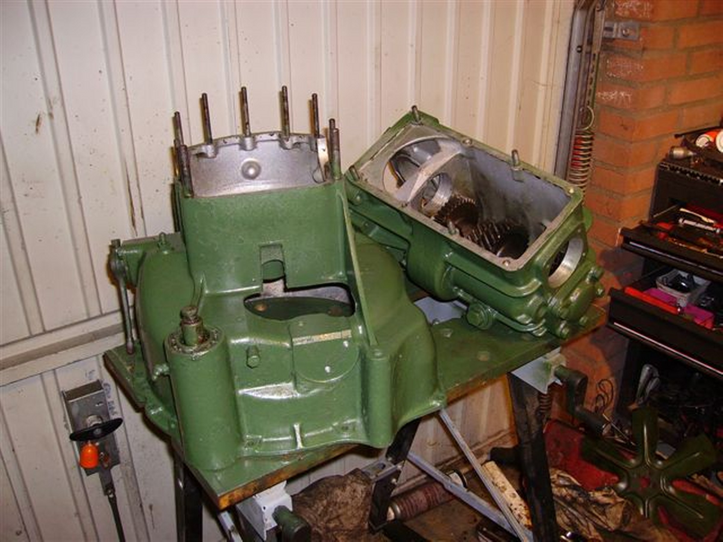
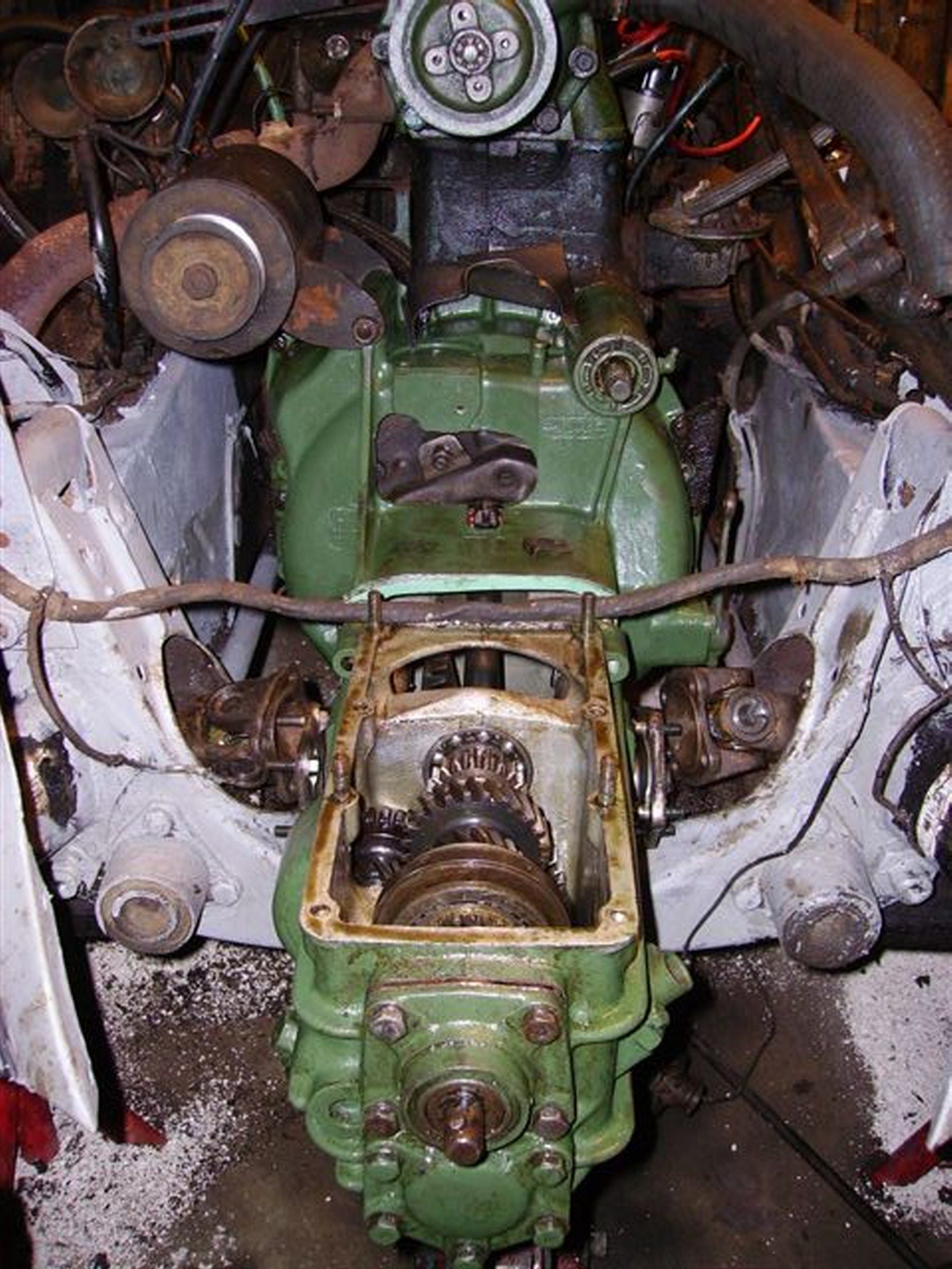
Krik onder carterpan (met veel stophout) en krik onder koppelingshuis
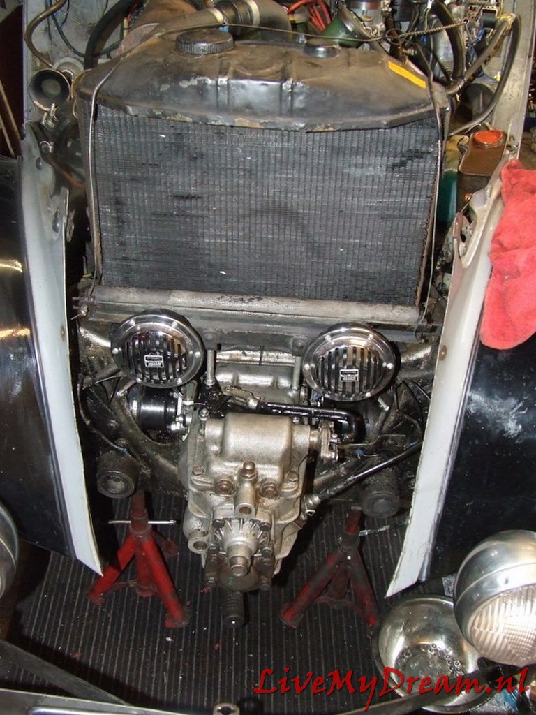
Alles eerst verwijderd: Motorkap, Grill, toeters en radiateurscherm, radiateur, ventilatorfan, poeli van de aandrijfas voor waterpomp e.e., subframe.
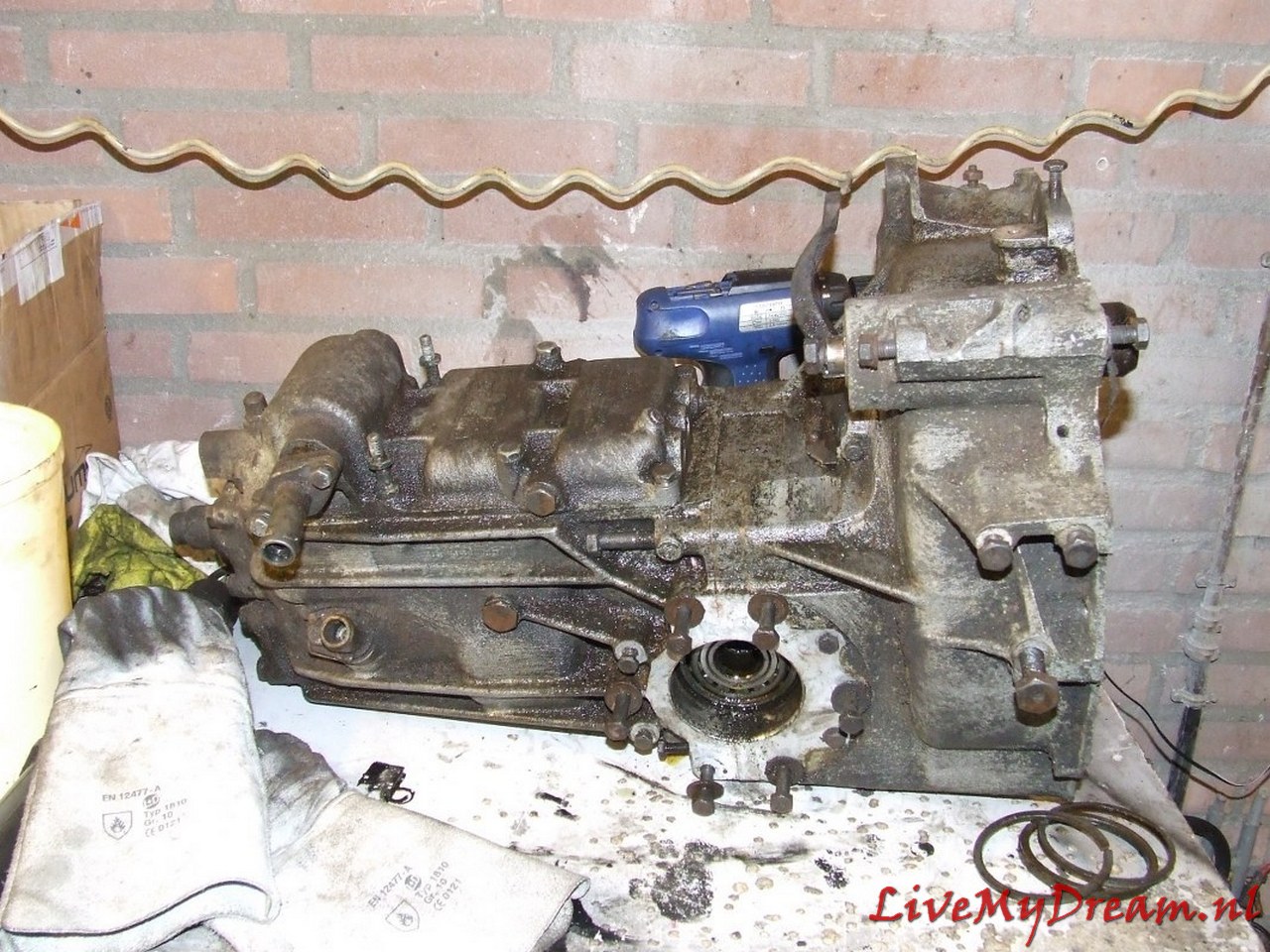
Voor de grote demontage-operatie van de bak, koppeling, aandrijving
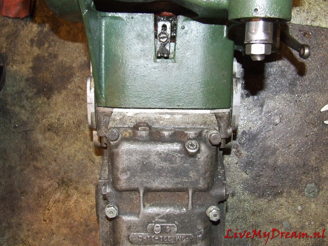
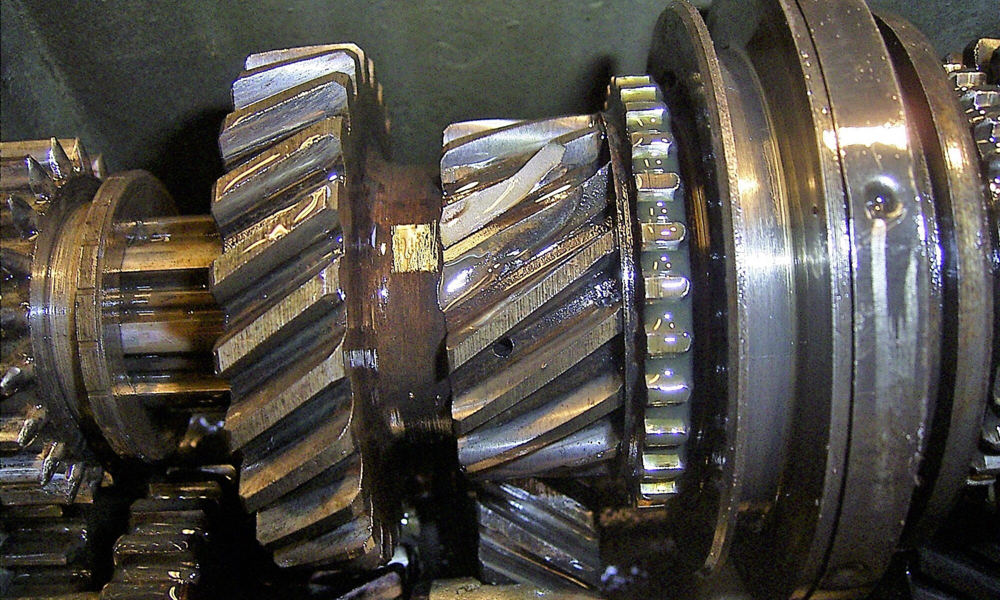
Bij afname van het bakdeksel bleken 2 tanden van het tandwiel van de 2e versnelling dat op de primaire as zit, te zijn verdwenen. OK. Valt even tegen. De tanden vond ik onderin de bak. 1 is oude schade en 1 is proefritschade.
Tandwiel bij de TAN club 2e hands besteld.
Zo erg kan het dus zijn in een bak.
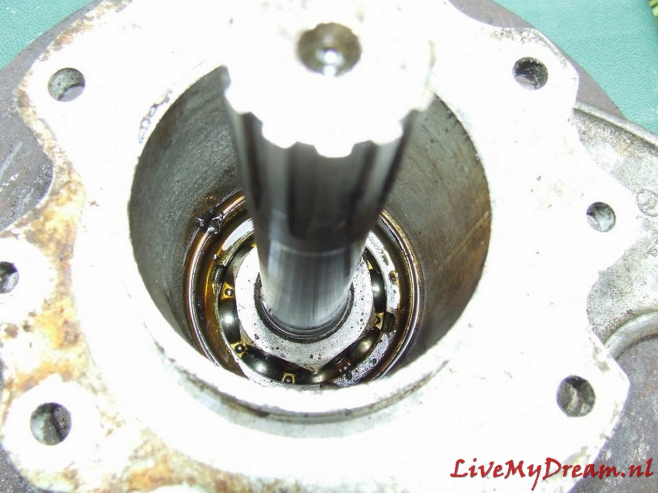
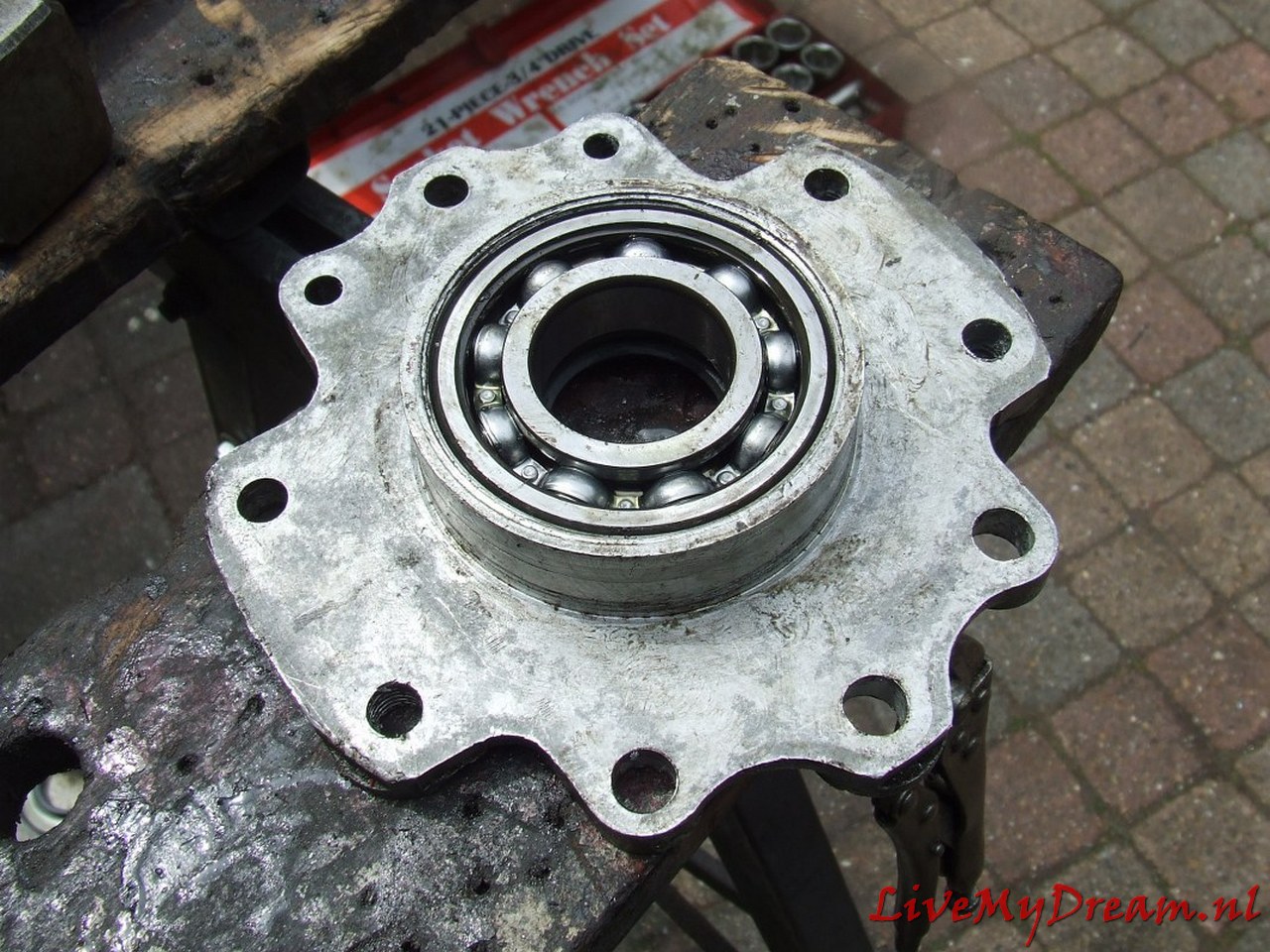
Speling op de lagers gemeten en is allemaal binnen norm.
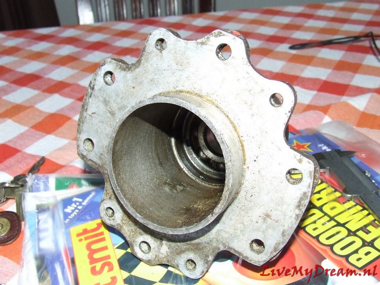
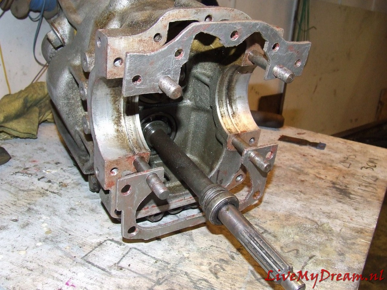
Om primaire as te verwijderen moet kroonwiel eruit. Gehele ‘ klokje’ verwijderd.

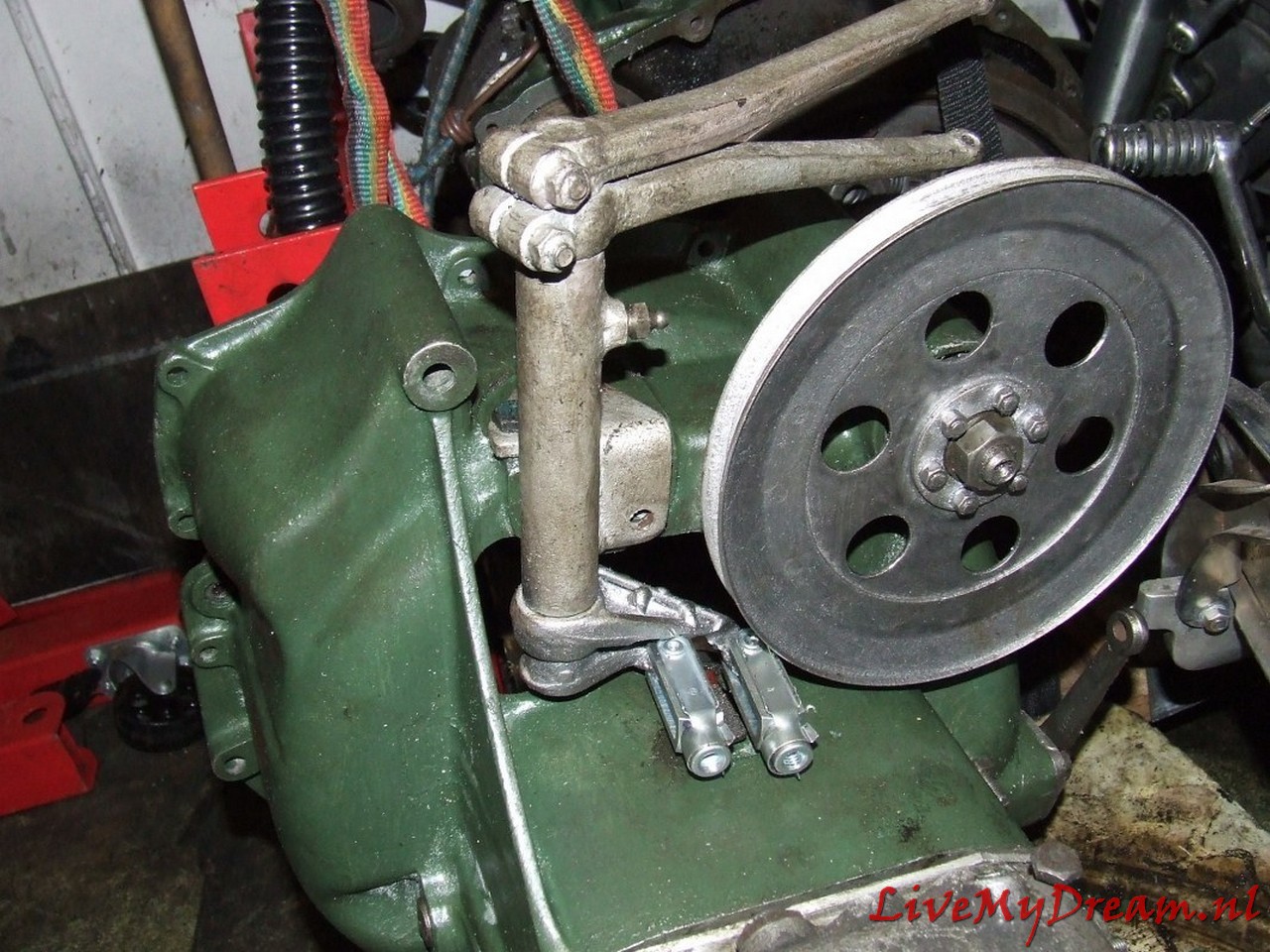
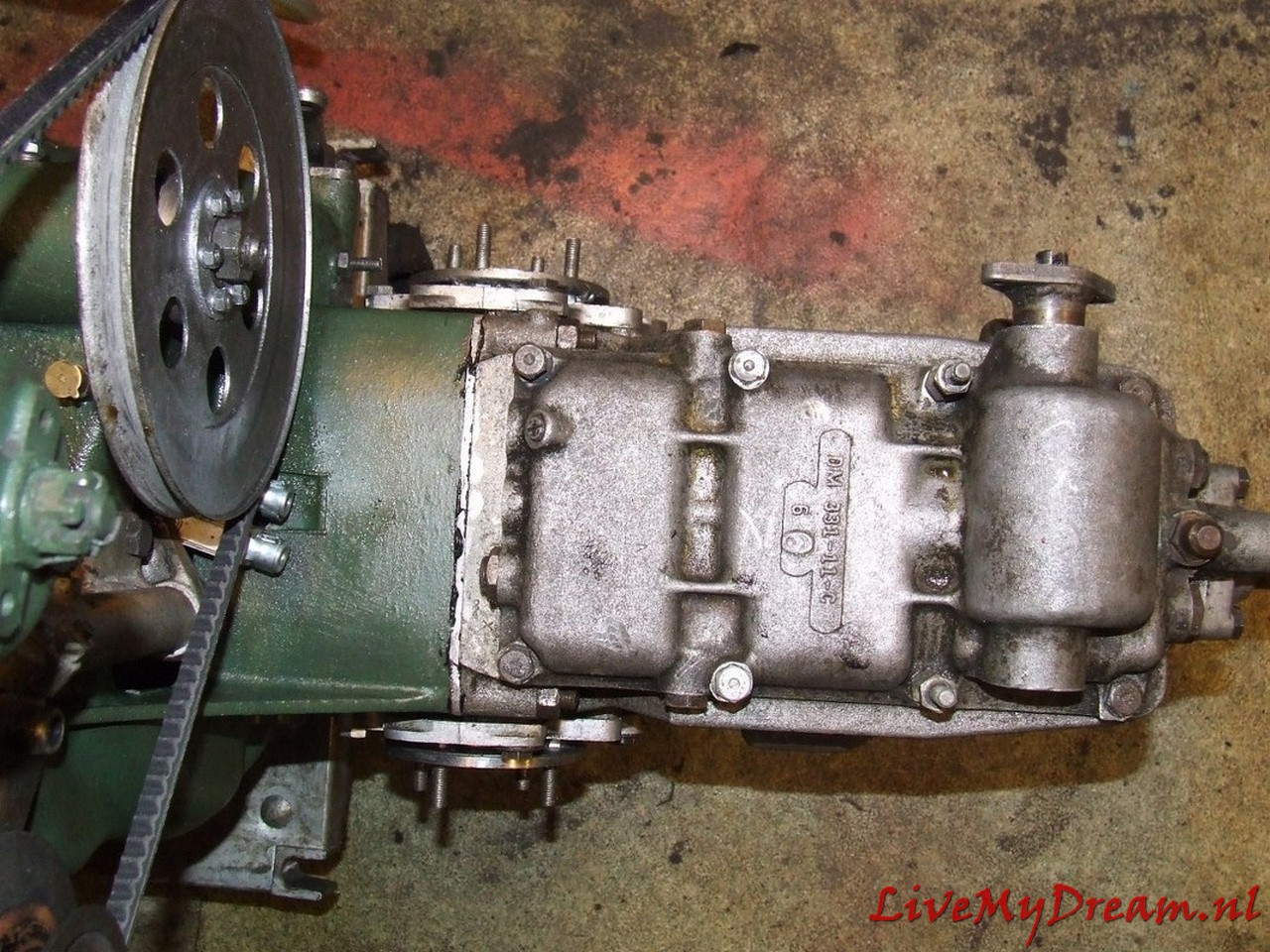
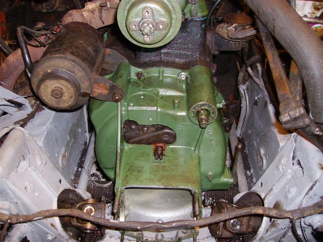
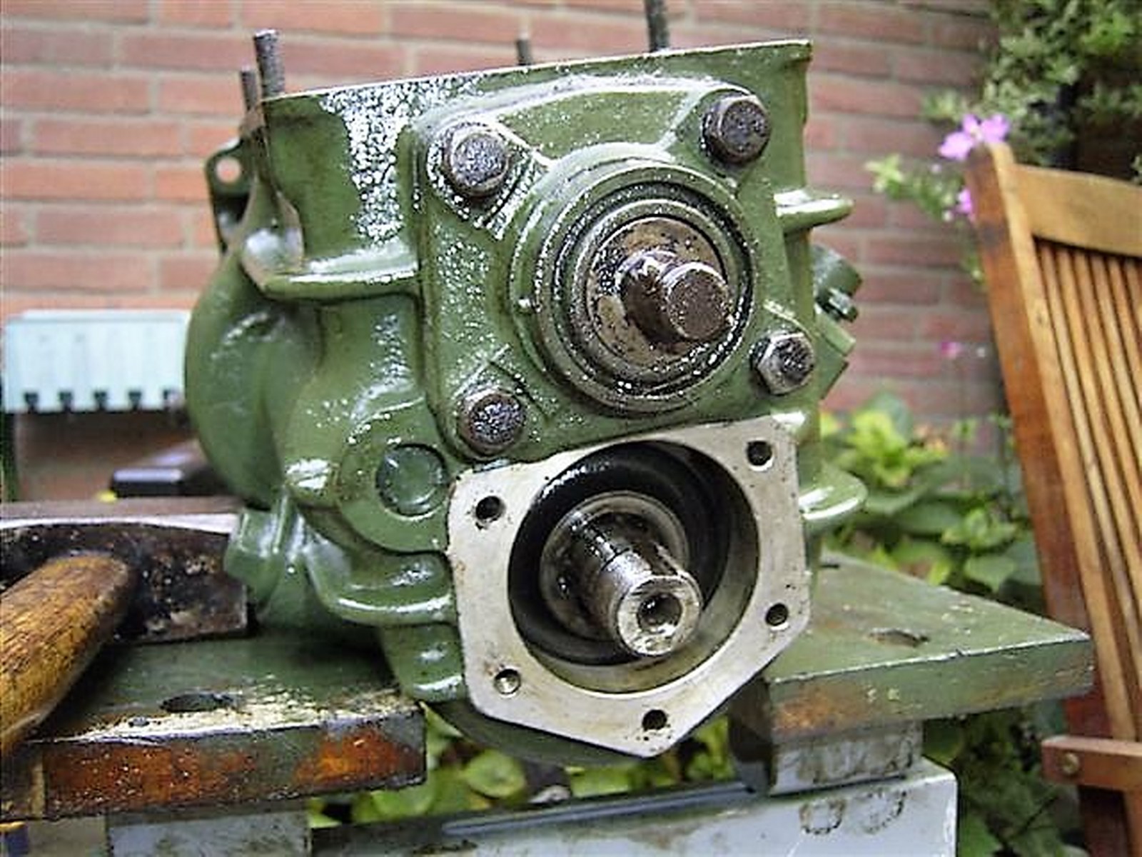
Mooi origineel groen gespoten
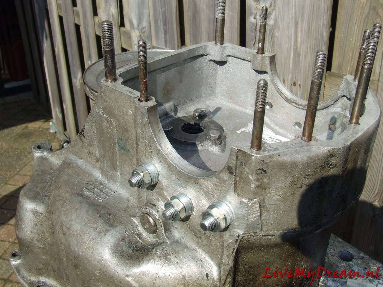
Zo. 10-9-2006: Koppelingsplaten vervangen. Koppelingshuis afgenomen, gereinigd en groen gespoten. De lastige M7 bouten naast de as van de aandrijving voor de waterpomp en dynamo vervangen door Imbus M8. De 2 gaten in koppelingshuis opgeboord naar 8 mm en schroefdraad in motorblok uitgeboord op 7 mm en getapt op M8 metrisch.
Kruiskoppelingen vernieuwd met nieuwe kruisjes en naaldlagerbussen etcetera.
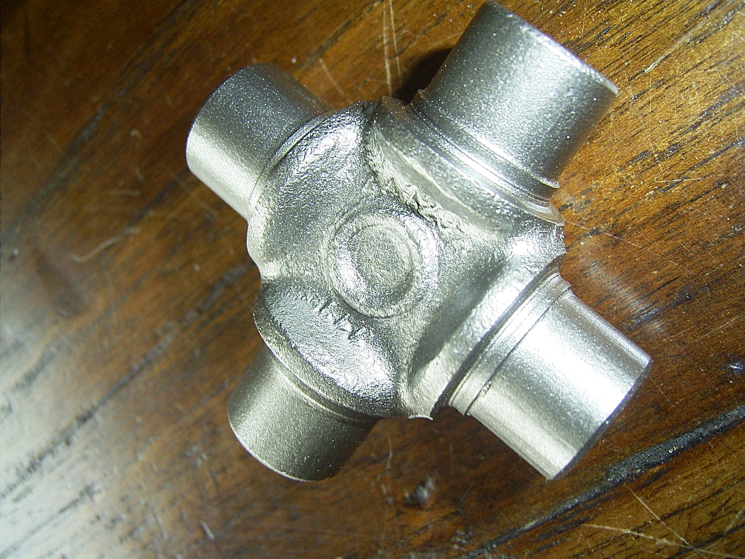
Kruistukje na grondige schoonmaakbeurt, herbruikbaar als presse-papier
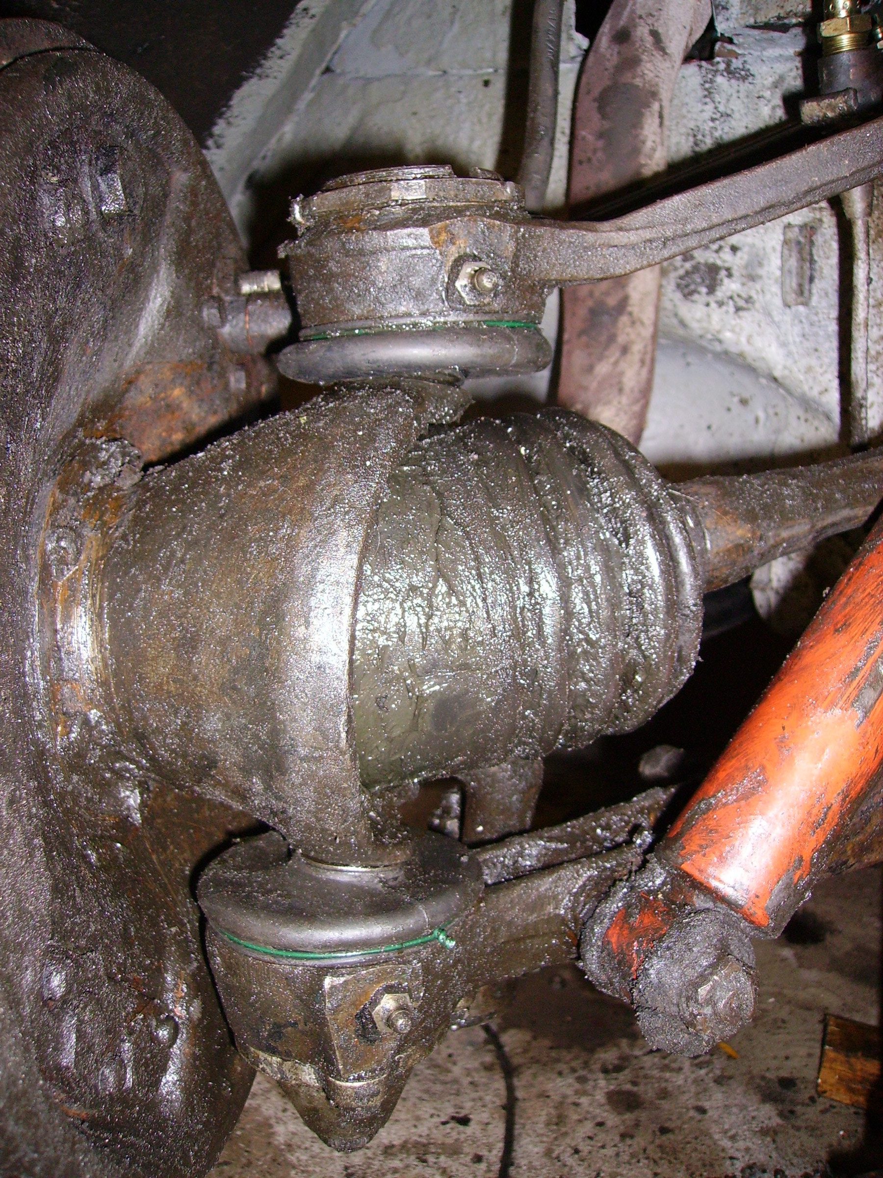
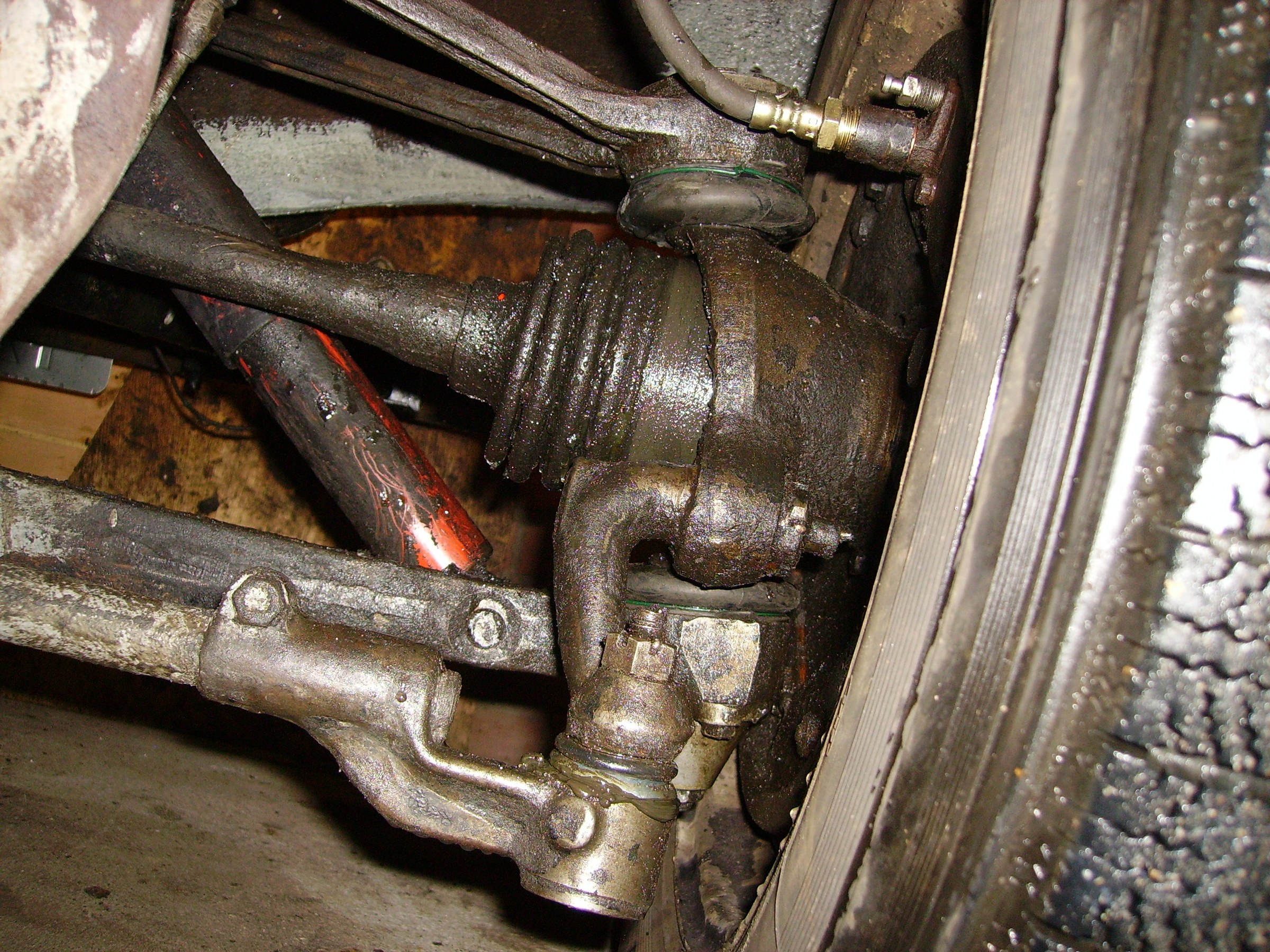
Gelijk stof- en vethoezen gemonteerd over de aansluiting van de difstukken op de aandrijfassen.
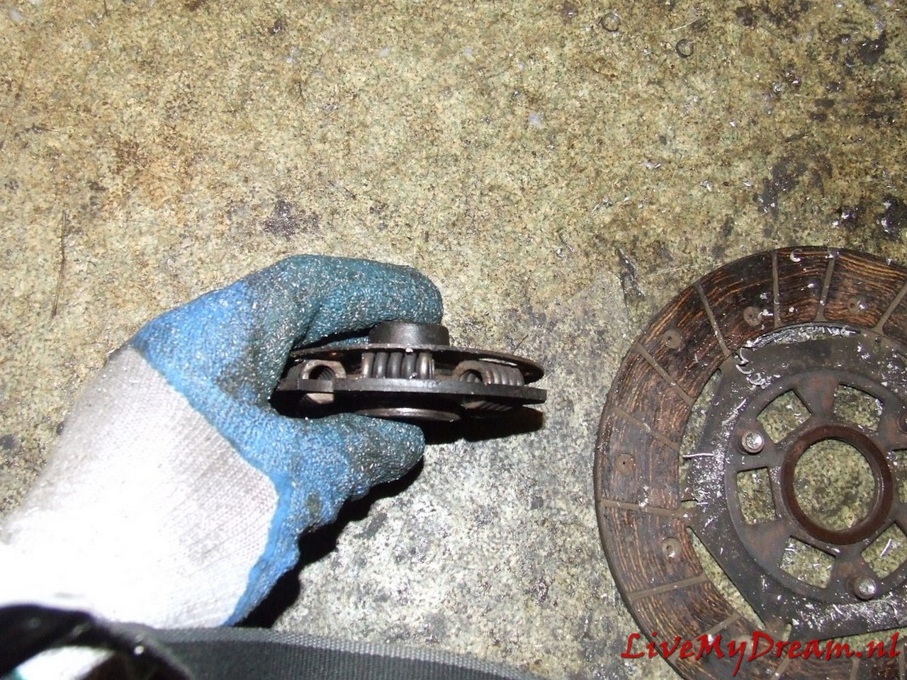
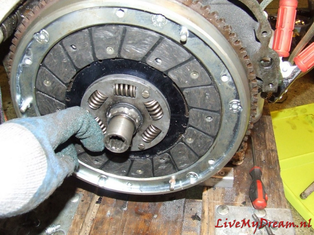
Druklager helemaal gereinigd en in compound gezet. Nieuw veertje dat druklager terugtrekt gemonteerd want dit was verdwenen. Drukgroep schoongemaakt met perslucht.
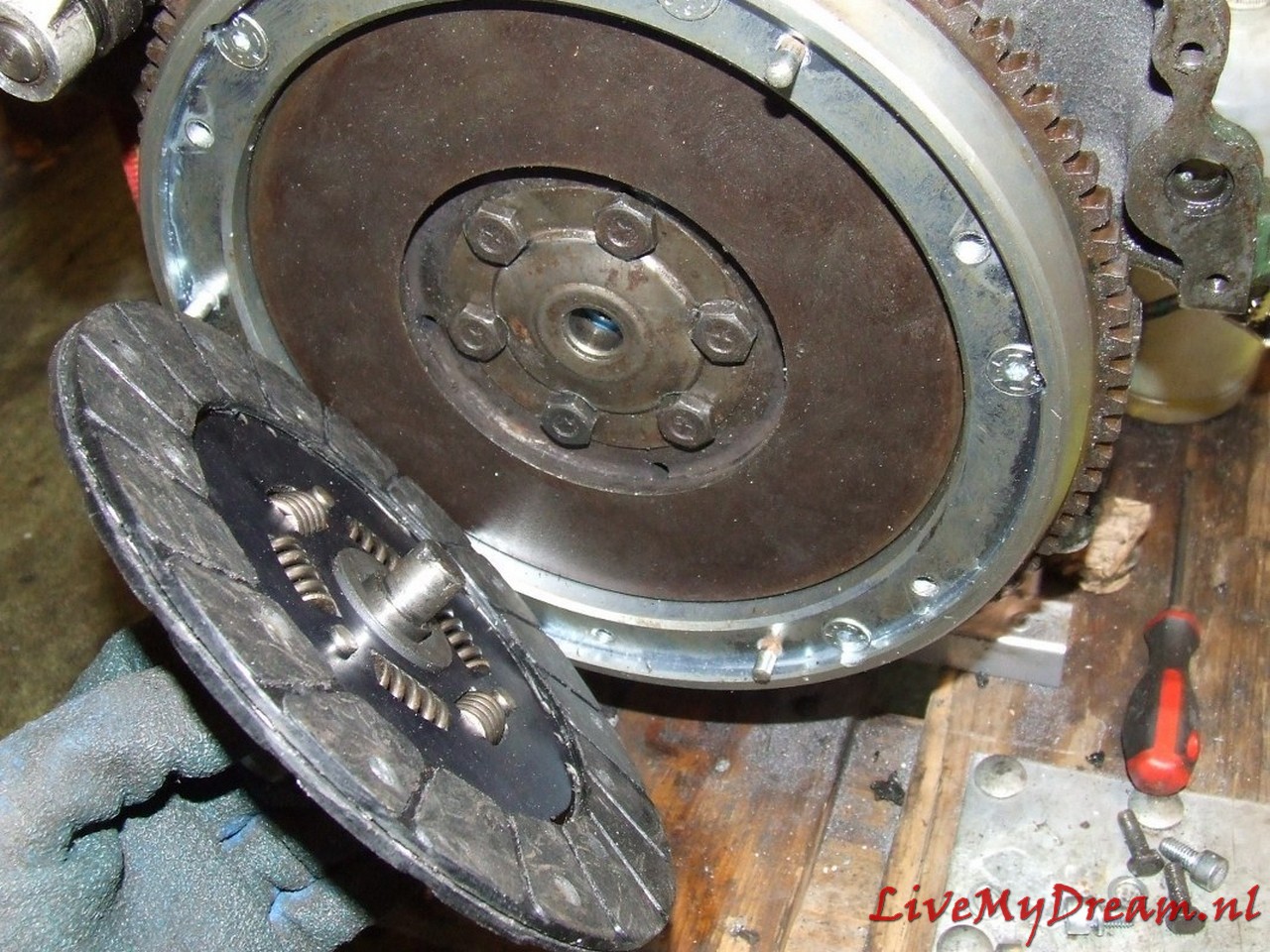
Koppelingsvlakken gereinigd van drukgroep en vliegwiel. Nieuwe koppelingsplaten gemonteerd.
Koppelingshuis gemonteerd.
Zo. 17-9-2006: Tandwiel 2e versnelling weer gemonteerd,
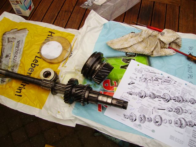
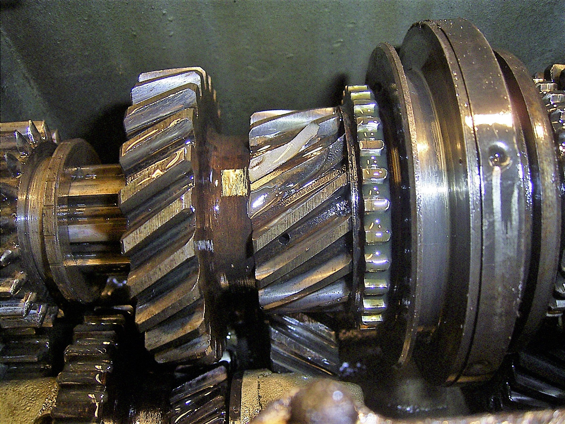
Primaire as met gemonteerd tandwiel 2e versnelling, boven de as ligt de synchronisateur en los daarin rechts het 3e versnellingstandwiel. Links net boven de as het tandwiel voor 1e c.q. achteruit.
Primaire as erin, pignonspeling gesteld op 1,3 mm tussen pignon en satelliethuis m.b.v. wegnemen van 2 shims en gelijktijdig invoegen van de pakking op voorzijde bak van secundaire as.
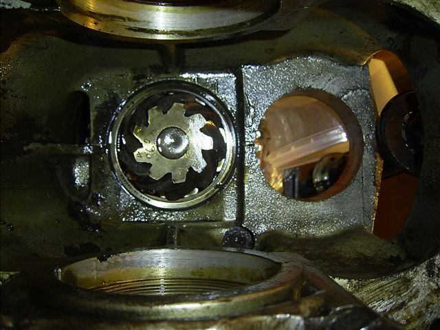
Pignon.
Voorzijde versnellingsbak met (boven) gemonteerde primaire as en (onder) secondaire pignonas.
Shim en lagerhuis secundaire as , Shims en voelermaten voor meten pignonspeling
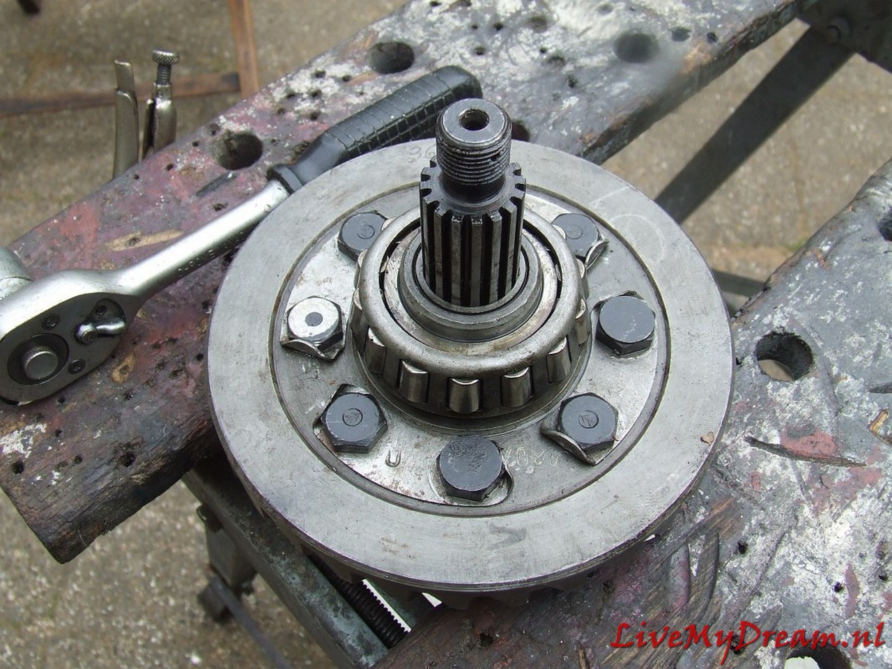
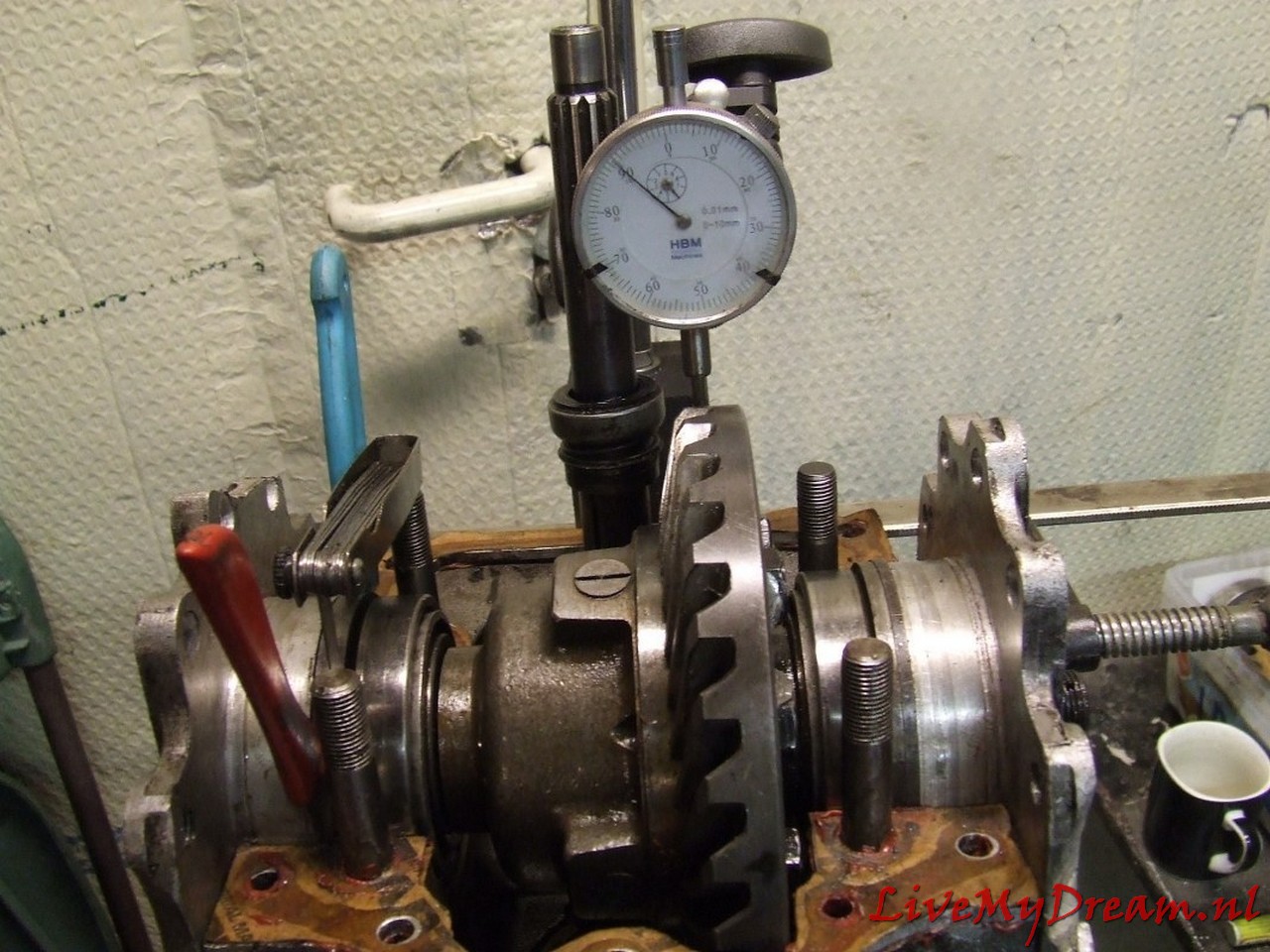
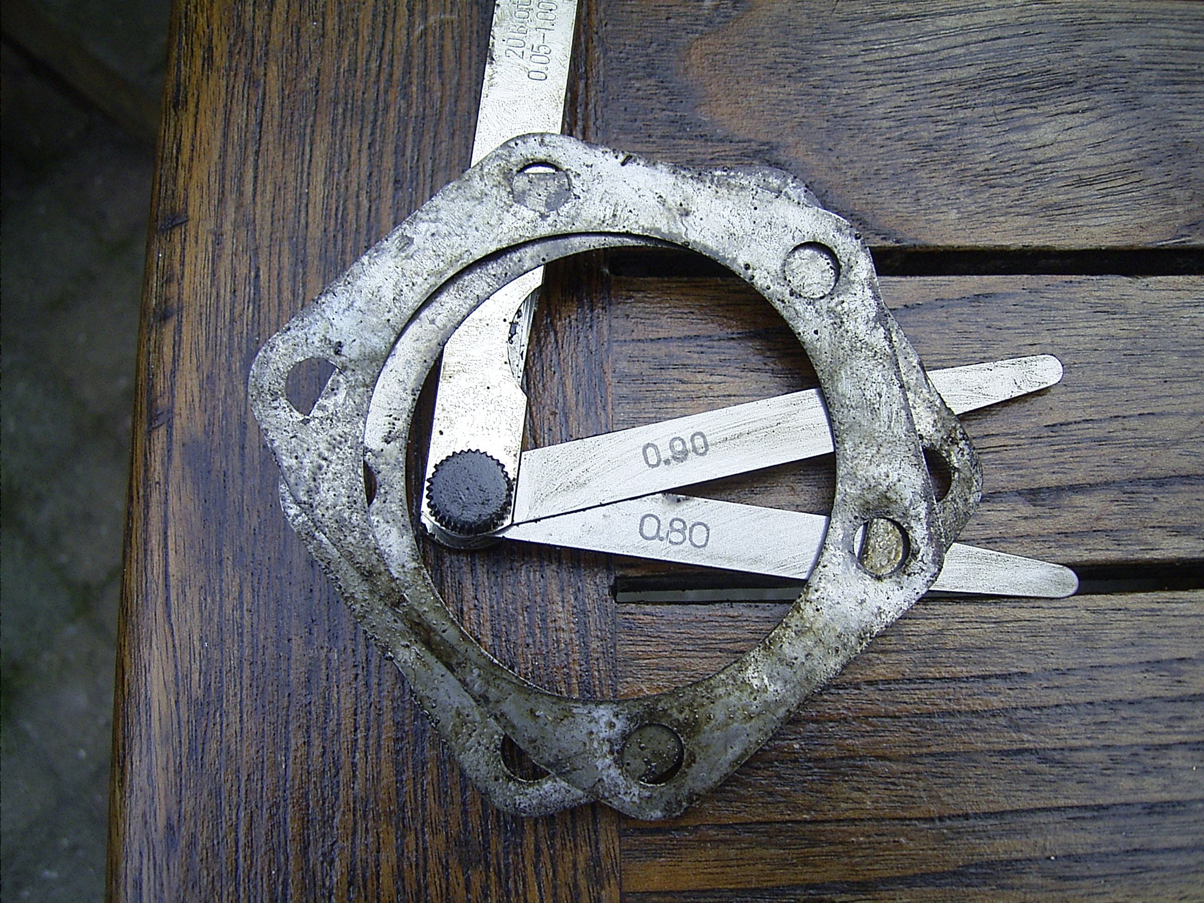
Wo. 20-9-2006: Kroonwielspeling op 0,2 mm gesteld d.m.v. stellen van de Timkenlagers van het differentieel.
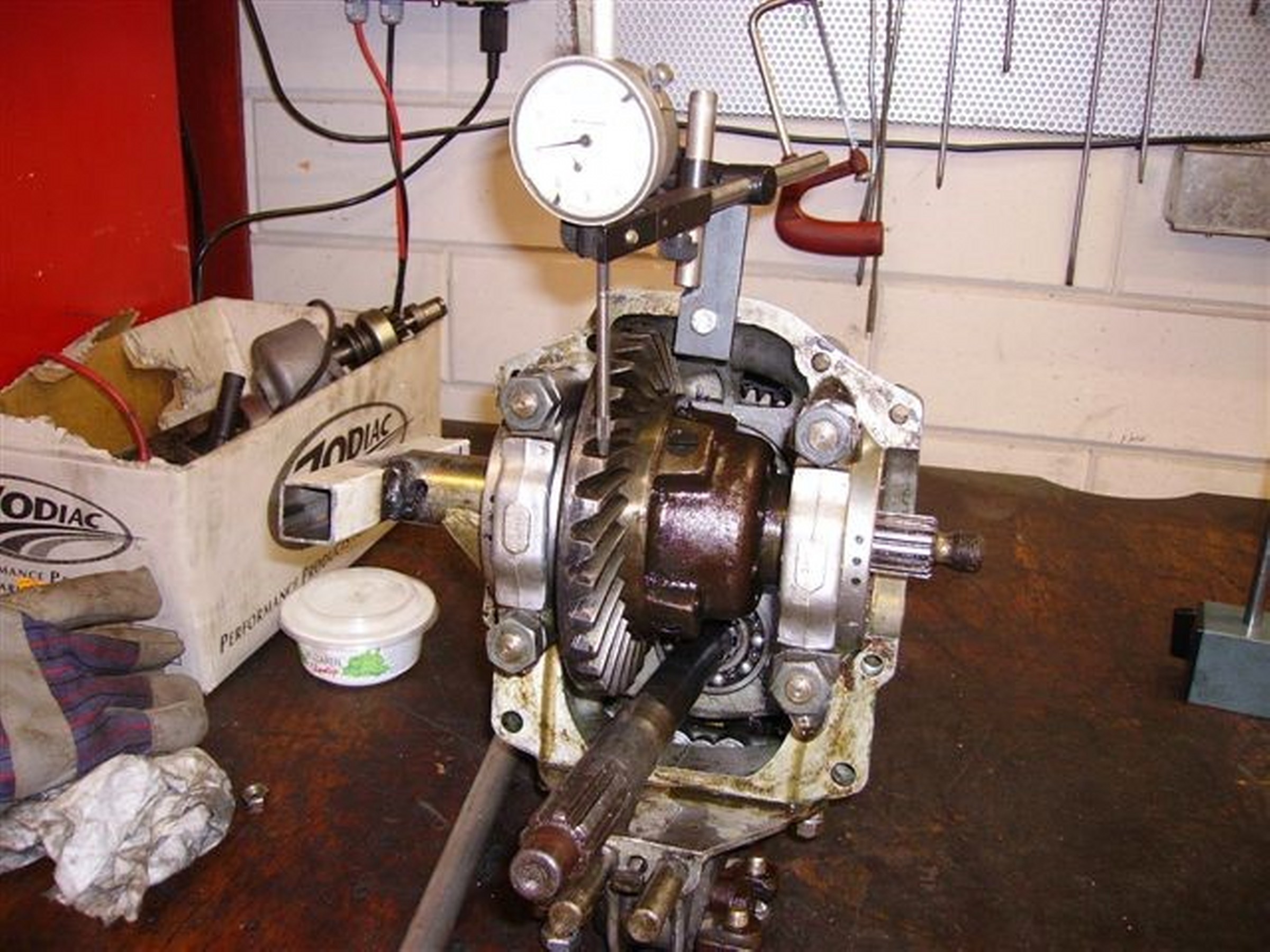
Praktijk van de meting in de garage van mijn broer
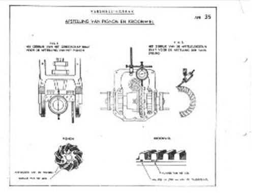
En de theorie uit het originele werkplaatshandboek Differentieelstukken gemonteerd met nieuwe keerringen. Pakkingen tussen koppelingshuis en versnellingsbak aangebracht, versnellingsbak aangebracht,
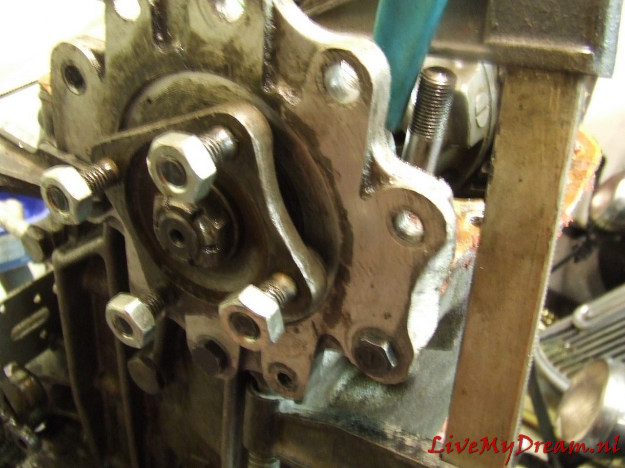
Aanschuiven van de bak op het koppelingshuis.
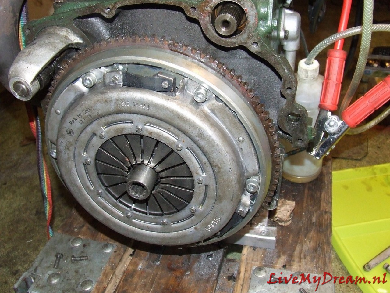
De korte aandrijfsasjes zijn hier nog los t.o.v. het differentieel. Aansluitingen tussen diffstukken en aandrijfassen aangesloten met nieuwe borgmoeren M8. Vervolgens alles weer gemonteerd: Vliegwiel, dynamo, waterpomppoelie, schakelstangen, beschermplaatje, afdekkap versnellingsbak met nieuwe pakking, olie bijgevuld, alles met nieuwe bouten en moeren gemonteerd.
Radiateur gemonteerd, auto schoongemaakt en ontdaan van alle vet en smeer.
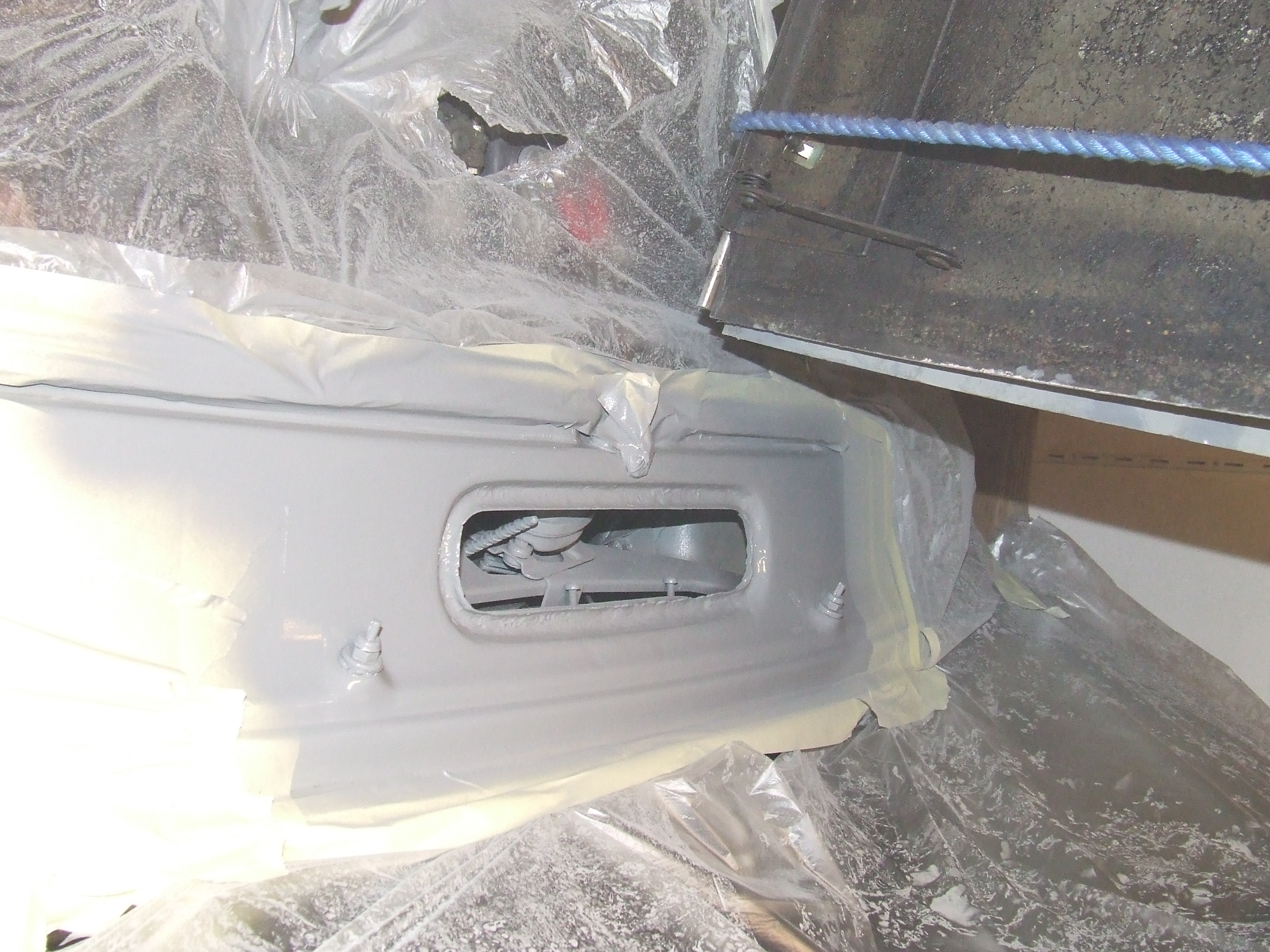
Alle roest verwijderd, Fertan opgebracht, afgespoeld en grijze Bodyschutz aangebracht op alle delen waar ik later niet meer bij kan komen.
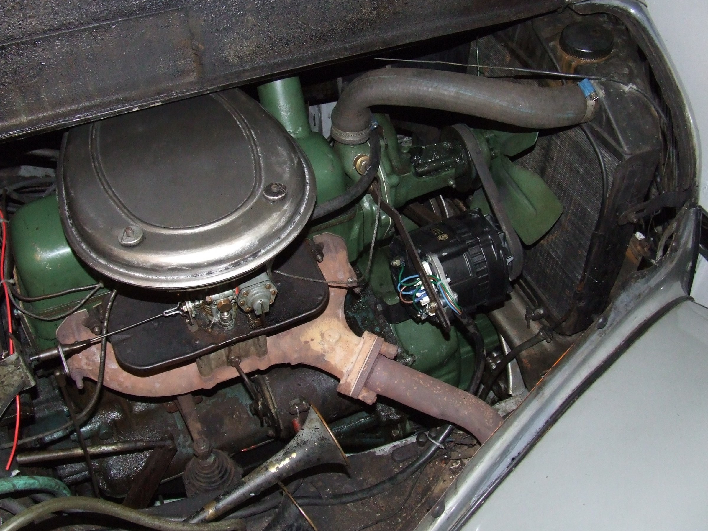
Auto zo ver gemonteerd dat de motor weer loopt en alles kan worden uitgeprobeerd
De mensen van de RDW hebben e.e.a. erg netjes opgepakt en zonder bijkomende kosten tegen inlevering van de vorige versie een nieuwe gemaakt. Lekker proefgereden op een hele zonnige vrijdagmiddag 22 september 2006. Aan alles gedacht maar toch vergeten benzine mee te nemen. De tank bleek nogal te lekken en dus stond ik na zo’n 4 kilometer helemaal stil. Gelukkig een hulpvaardige broer die op de motor met 5 liter reservebenzine aankwam. Benzine erin, even doorstarten en gaan met die banaan!
Onderweg wat olie verloren omdat de klepdekselpakking die van rubber was: zo’n mooie nieuwe, ongeveer 2 centimeter langer was geworden. Maar even door broerlief professioneel dichtgekit.
De benzinetank lekte zo erg dat hij geheel leeg is gelopen.
Naar huis gereden met een slang in de reservetank. Paar liter benzine erin en dan kom je wel weer thuis.
Het positieve nieuws: Remmen, sturen, (ont)koppelen en schakelen als een zonnetje. Wegligging prima, geen rare bijgeluiden uit motor of bak enzovoorts.
Moet nog wel de carburatie checken op acceleratiepomp en sproeiers want stationair gaat prima, voluit gaat prima maar daartussenin gaat het met horten en stoten en dat is erg jammer.
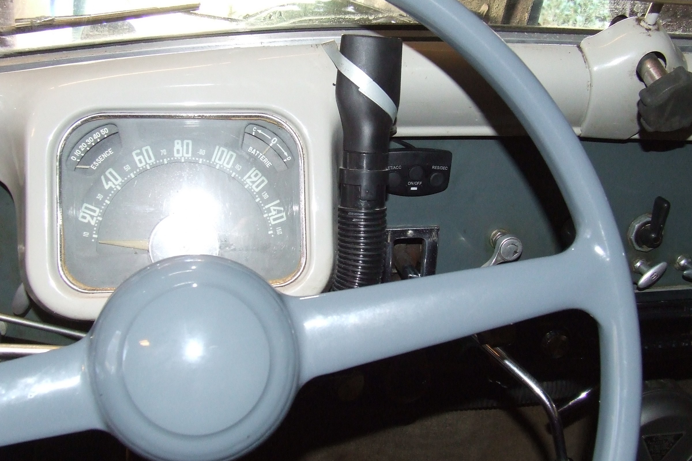
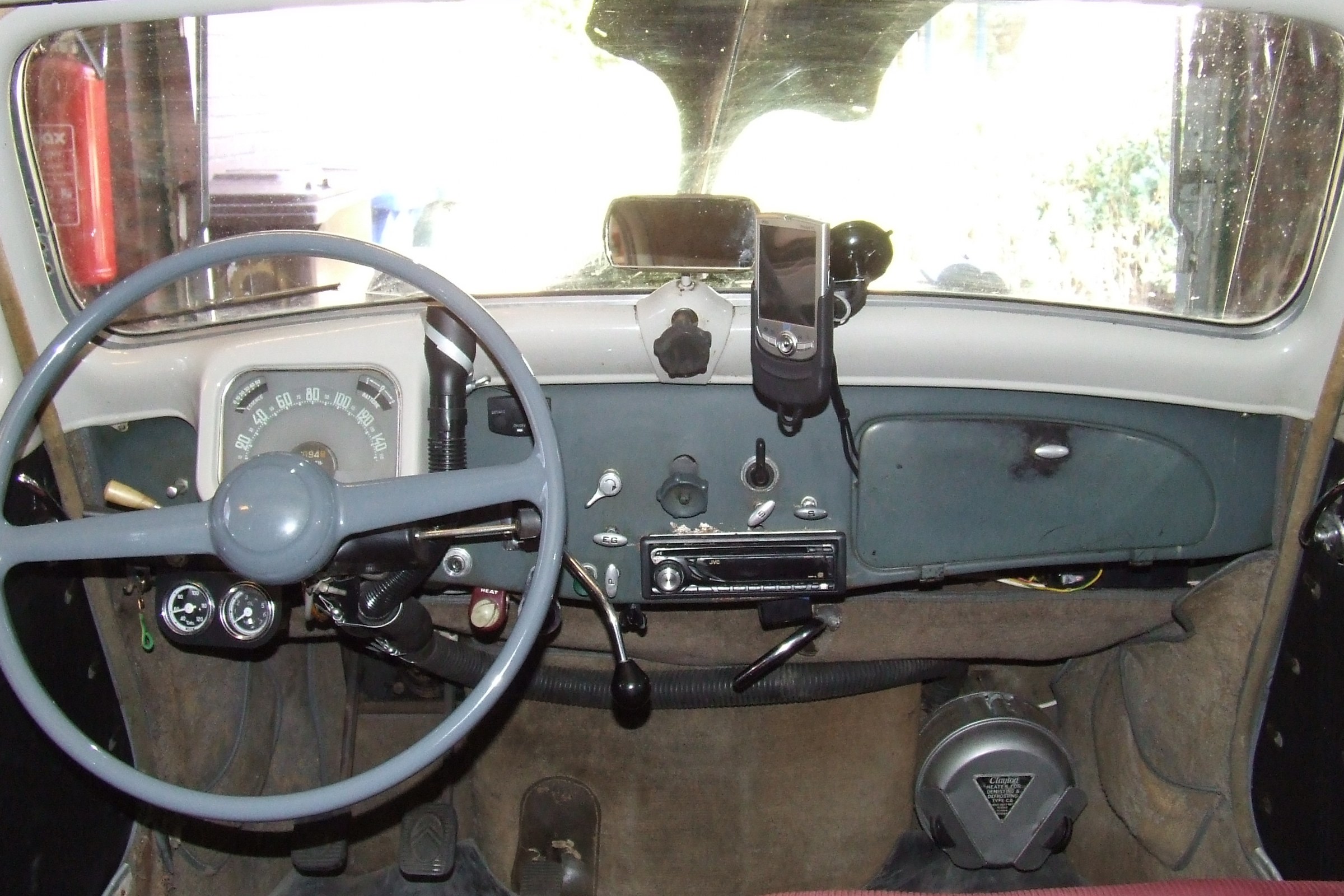
Inmiddels de luchthoorn gerepareerd en dat is errug leuk onderweg. Tweetonig claxoneren op z’n ouderwets met een speciale handel aan het stuur.
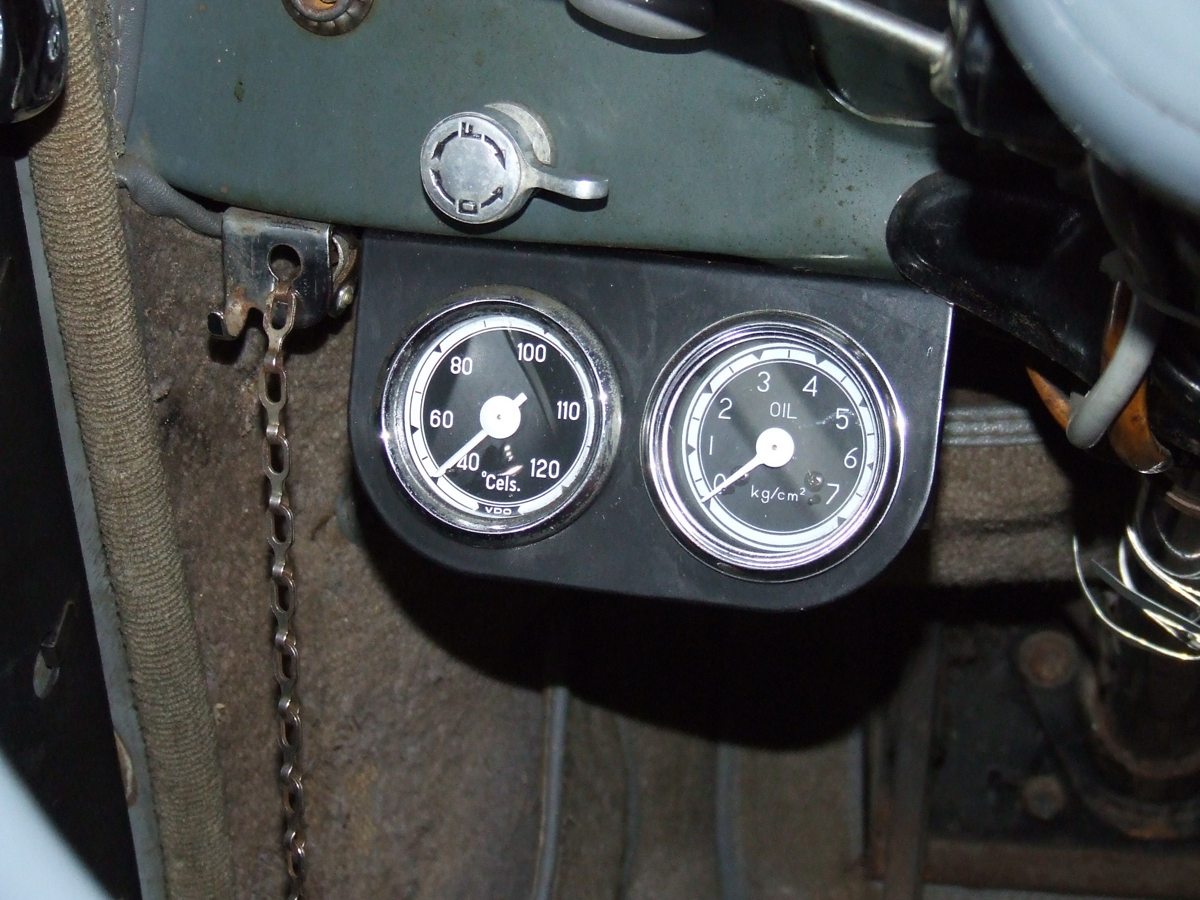
Inmiddels alle instrumenten en controlelampen vervangen, dimmer van de cockpitverlichting vervangen en een heuse stuurschakelaar gemonteerd voor de clignoteur. Ook het lampje in de oorspronkelijke schakelaar vervangen.
Antenne gemonteerd voor de 6 Volt Philips autoradio die het ook errug leuk en origineel doet.
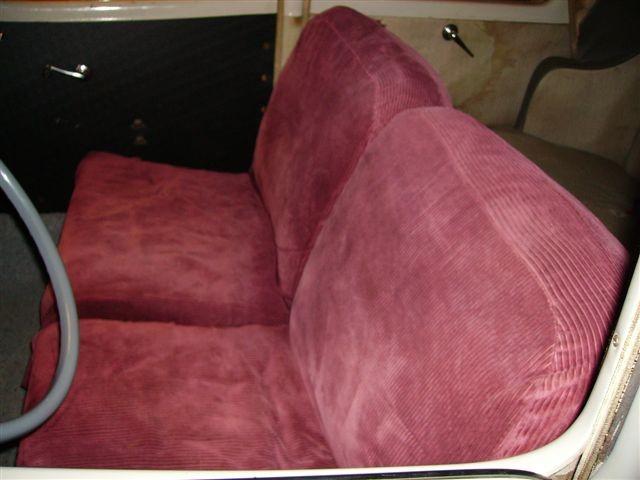
Binnenzijde met de bijgeleverde ribcoard (rode) stoelhoezen
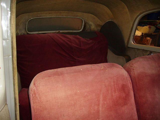
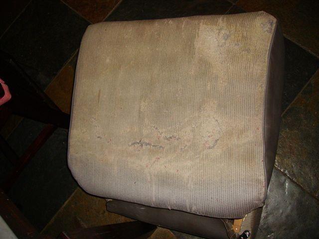
En de oorspronkelijke bekleding natuurlijk, met hier en daar een slijtageplekje.
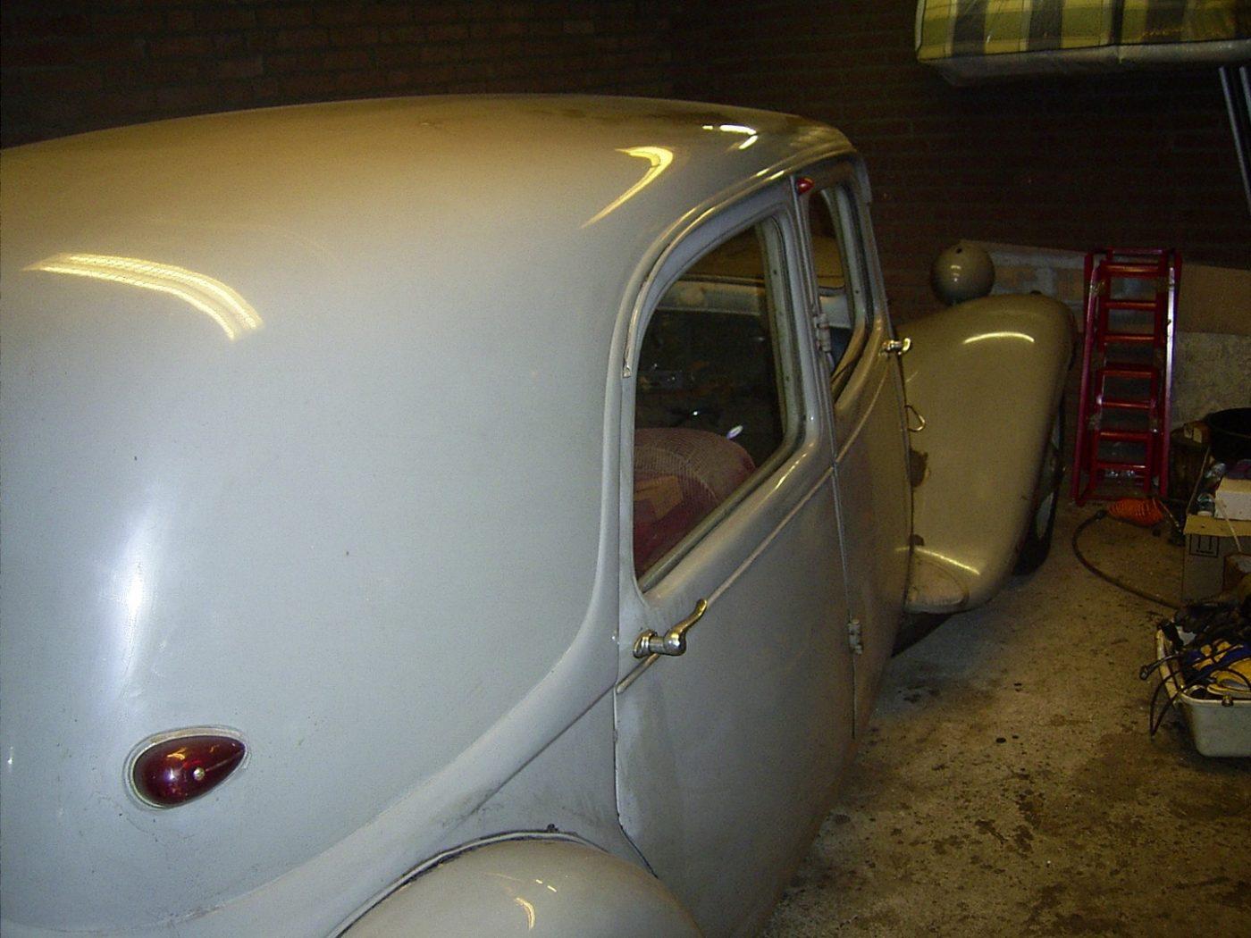
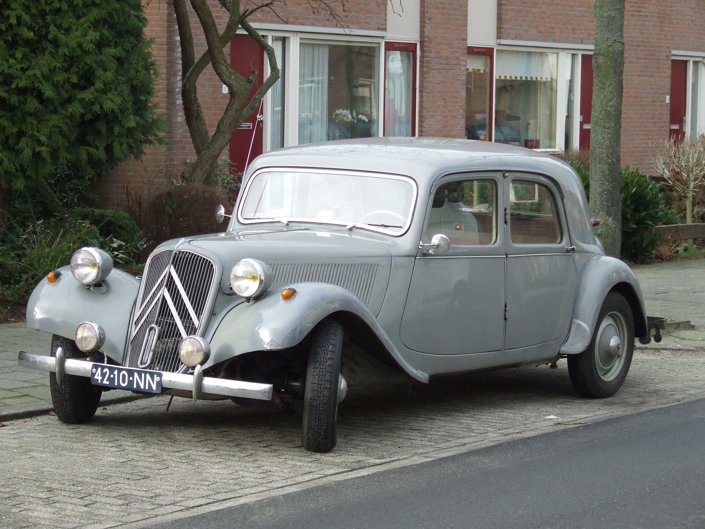
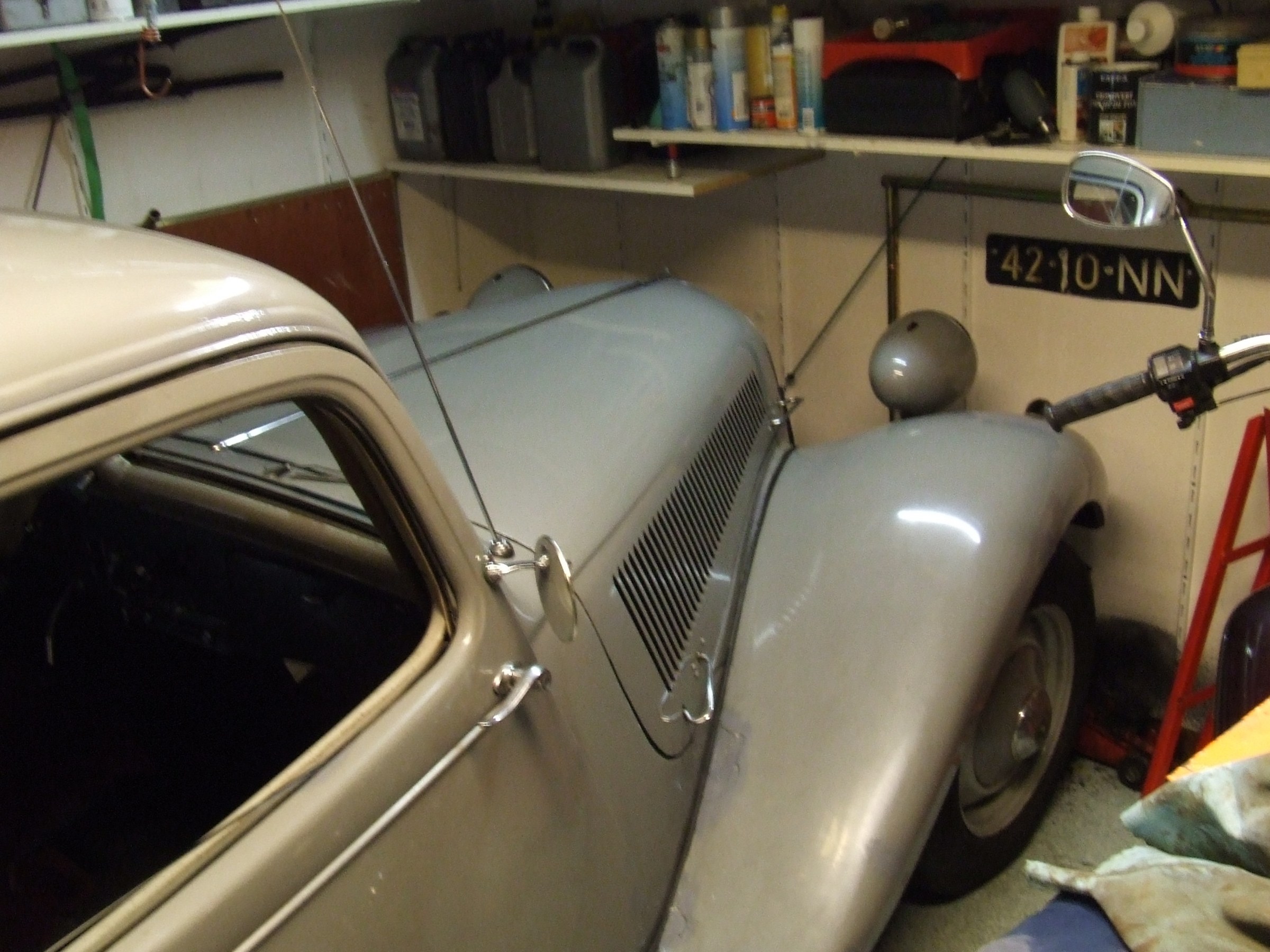
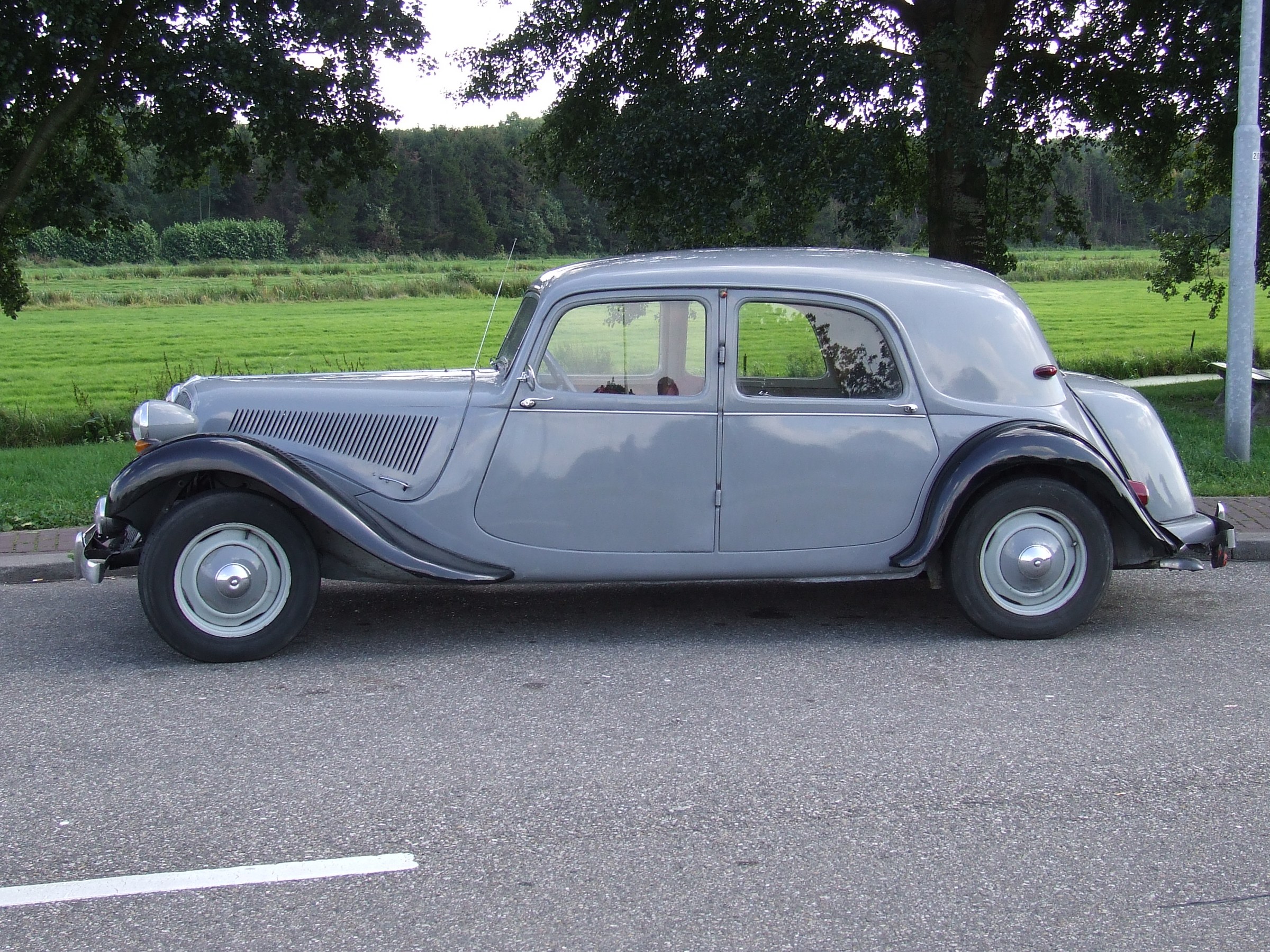
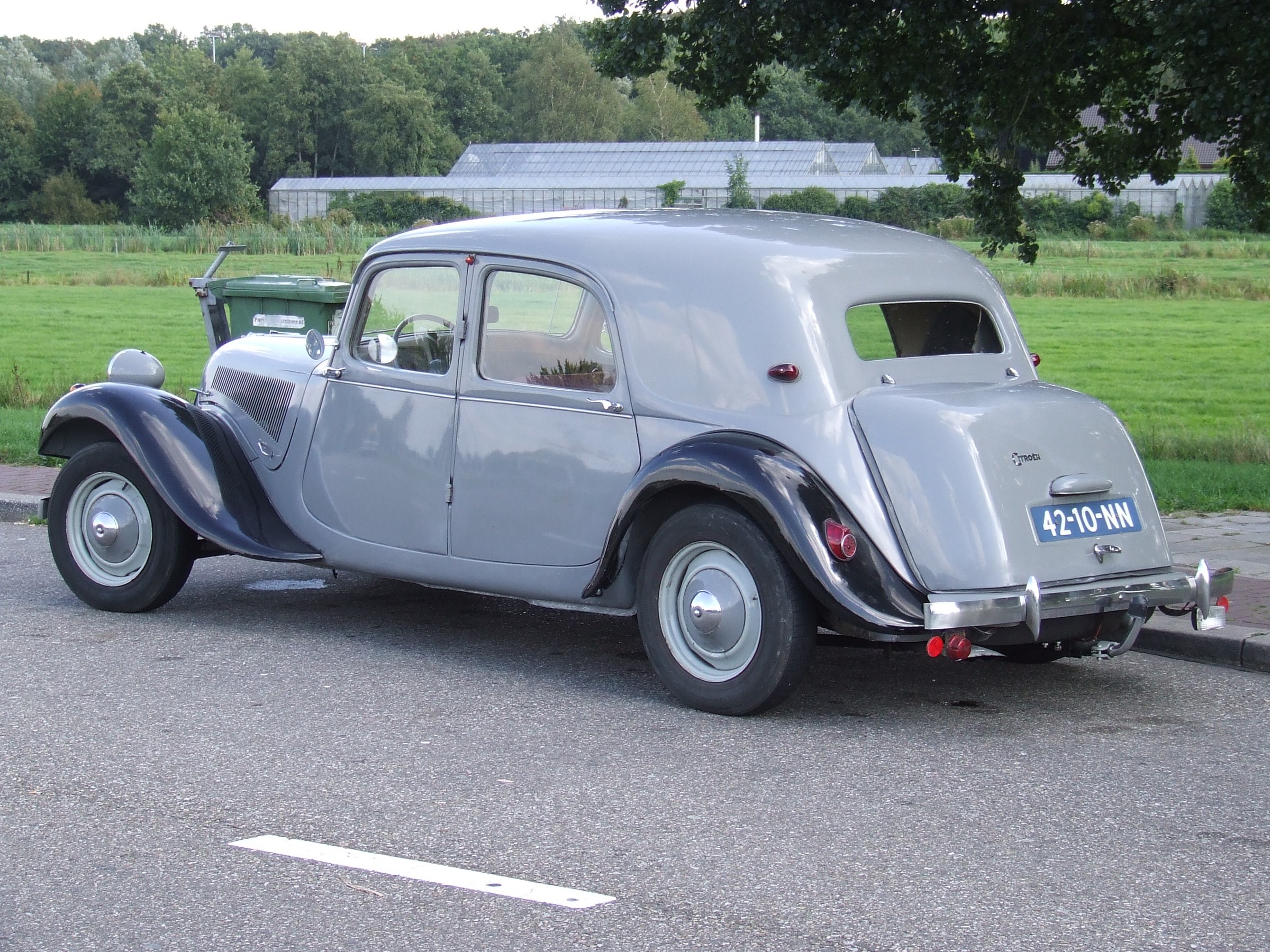
Achter- zij aanzicht in de garage


Leather dust covers steering mounted
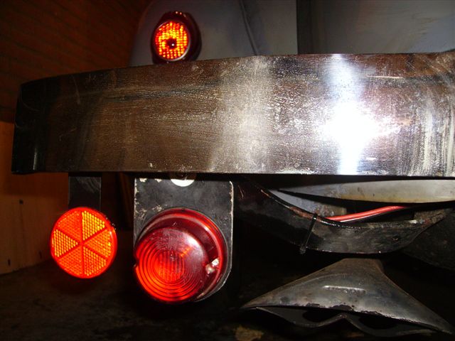
Rear indicator bulbs replaced and 25 watt bulbs mounted
Citroen plate mounted
New ignition coil
Bodywork repainted on rusted parts
Floor panelling in front of the seats (temporary)
Valves set
Ignition set
APK on 12-10-2006
Actions following MOT done (14-10 till 30/10/2006):
| B |
| 4 |
| 1 |
| 5 |
| 7 |
| 2 |
| 0 |
| 1 |
| 1 |
BEFORE THE ACTION
AFTER THE ACTION
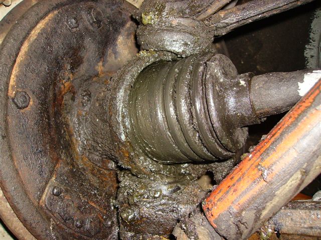
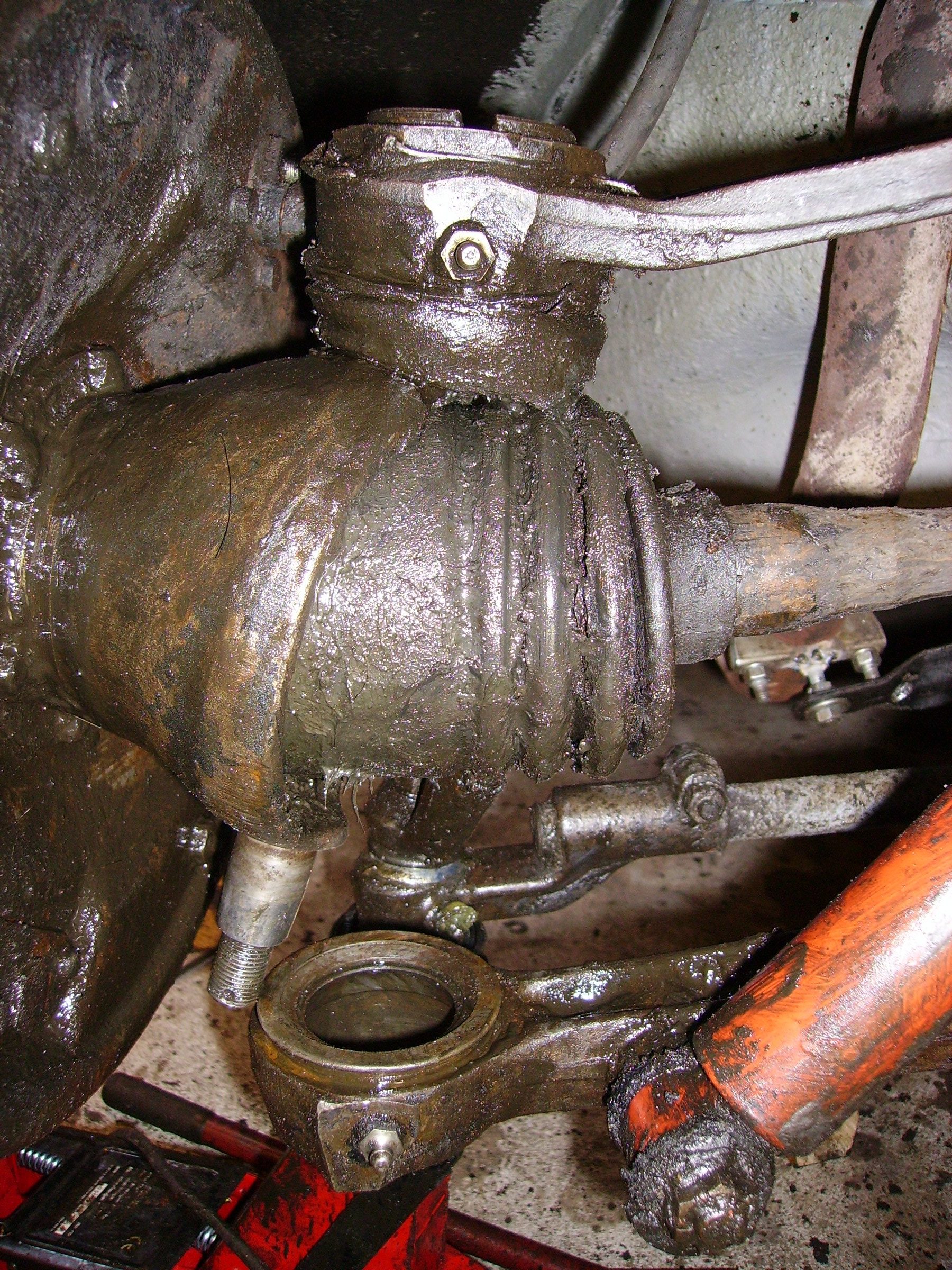
502: 4 pieces of greasebags on steering knuckles L+R replaced below + above
112: Front left headlight replaced by new glass and a new (56 years new in original box, cost 109 Euros) mirror, both headlights also adjusted to height
801: Rear right wheel replaced by a spare wheel and brakes loosened a bit because of some wear on the right rear side

Drive on Sunday 15-10-2006
Finished for now, had an MOT and after a short recovery we will continue with the structural things like electrics, sheet metal and paint, interior and so on…
Ordered 13-11-2006:
Air filter rubber carburetor 11D
Carburetor repair kit Solex 32/34 PBIC
4 pieces 11CV ball joint key
Pedal rubber brake/clutch
Mudguard trim, gloss black Ø7mm
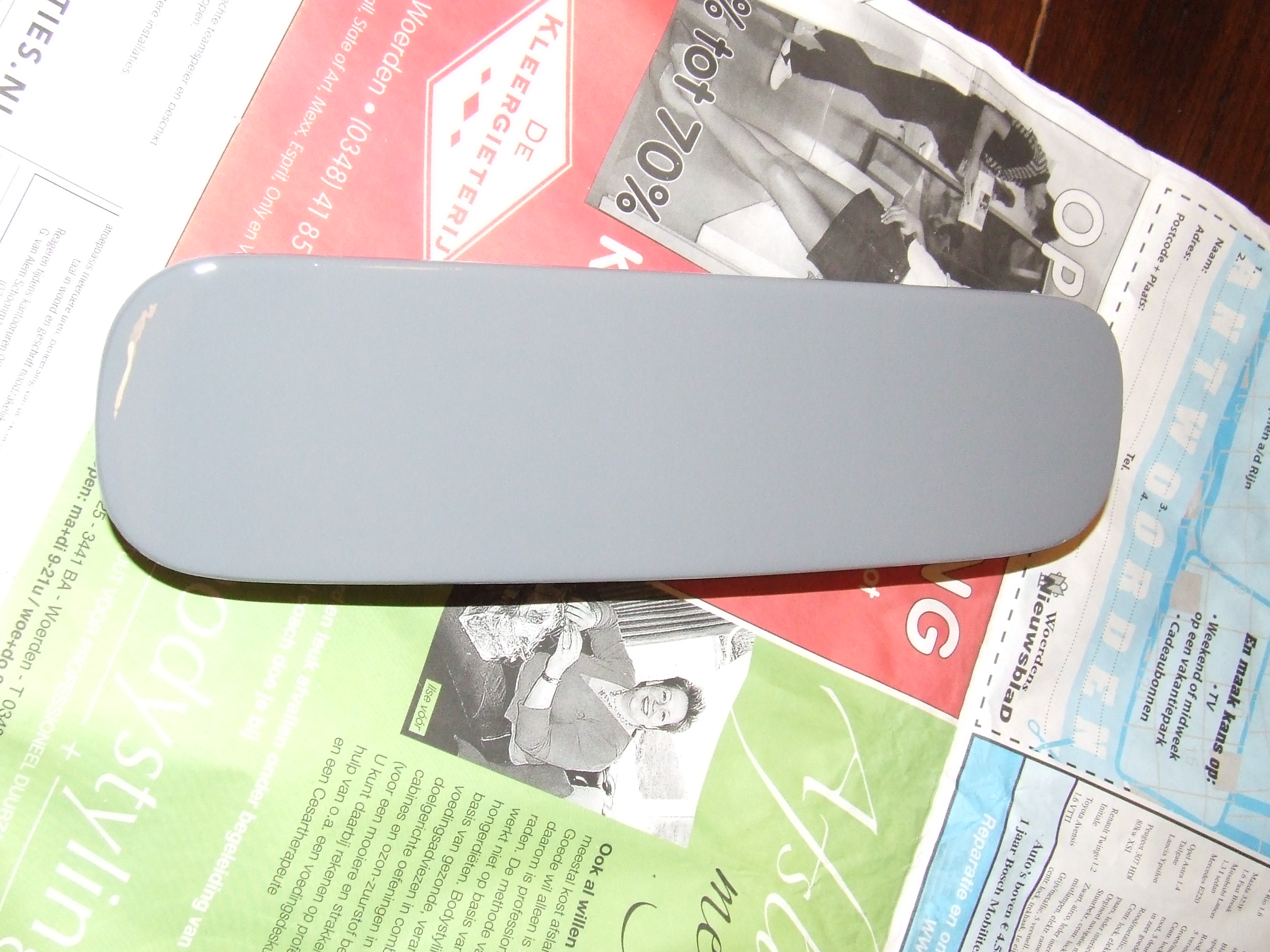
Spraycan window strips light grey
Alternator 7,4V/35Amp + support
Voltage regulator electronic 7V
Later done (2007):
Body where needed spray painted in grey (original color)
Upholstery and felt bottom and side/under dash ordered 5-10-2006 from CTA
Buy chrome inner caps
Tankcap with lock
6 to 12 Volt converter
Better sound, radio and CD with MP3
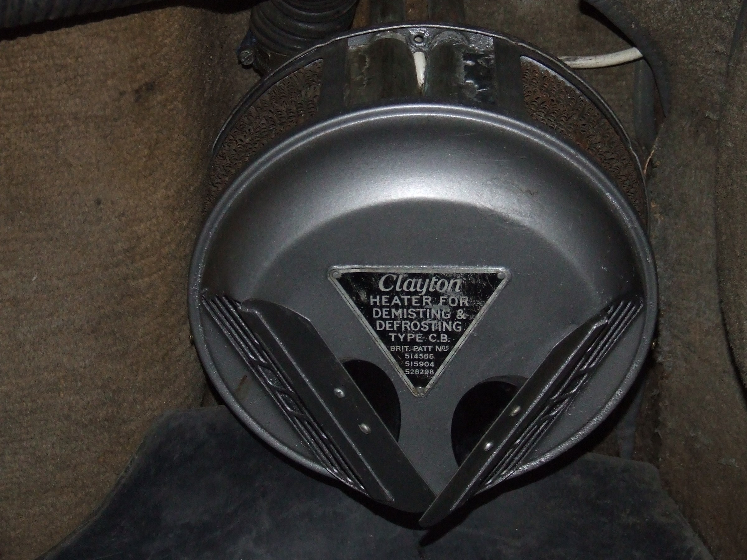
Heater mounted (Clayton) and windshield heater connected
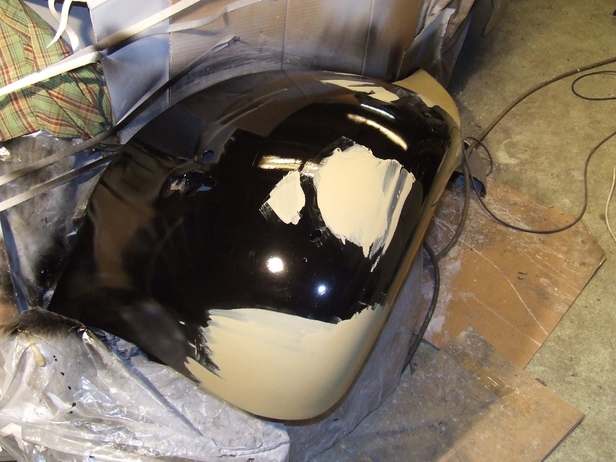
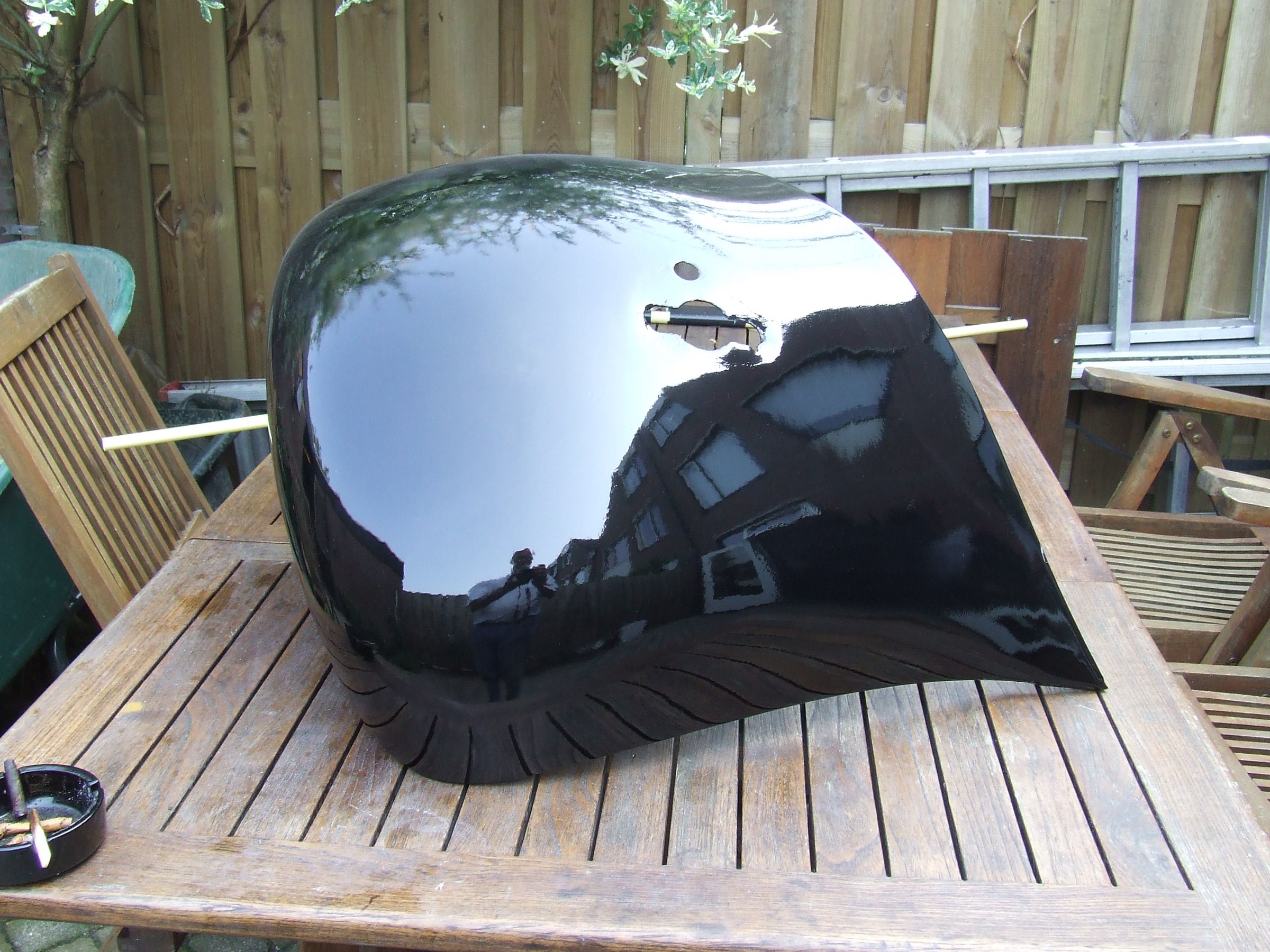
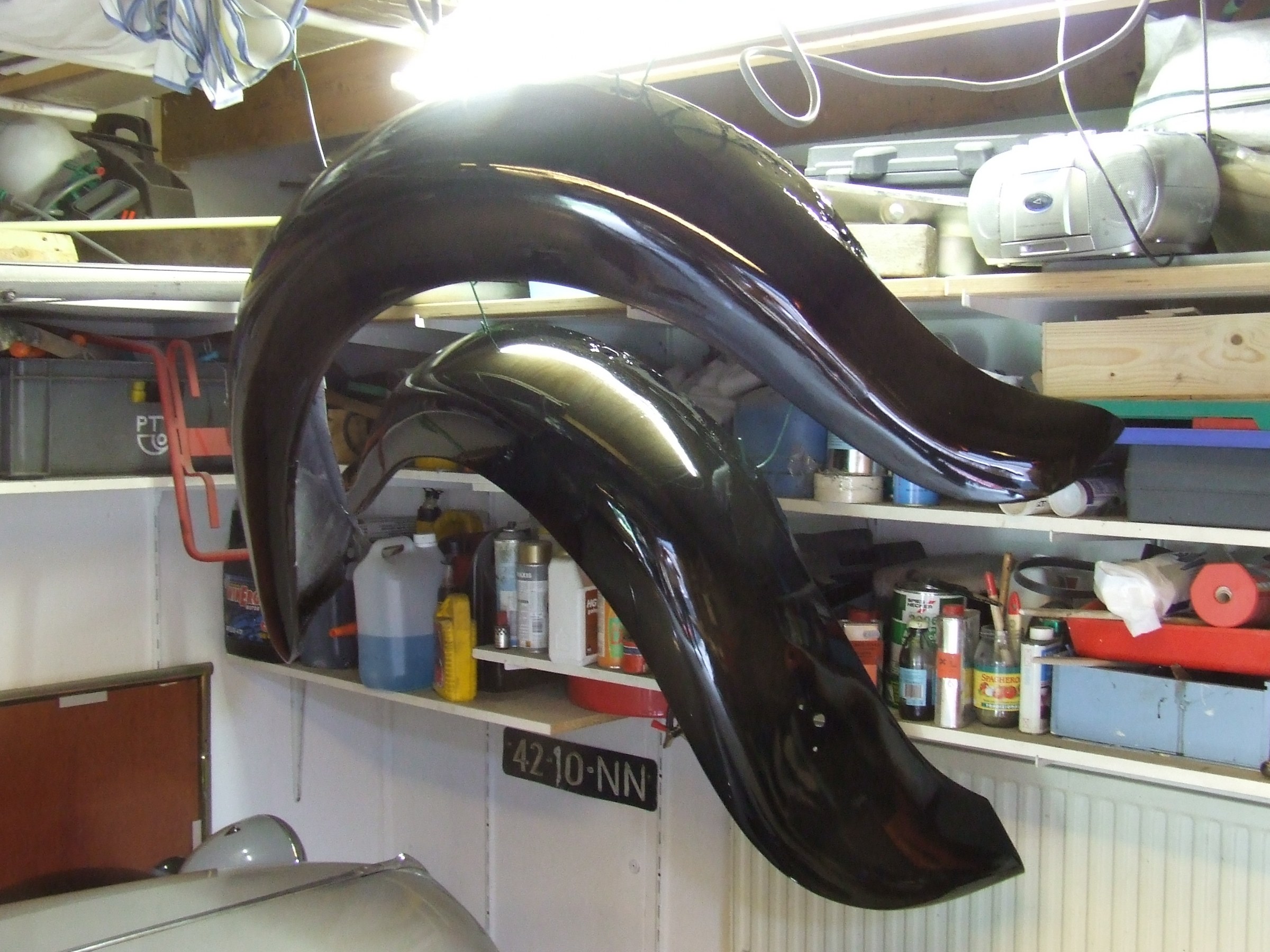
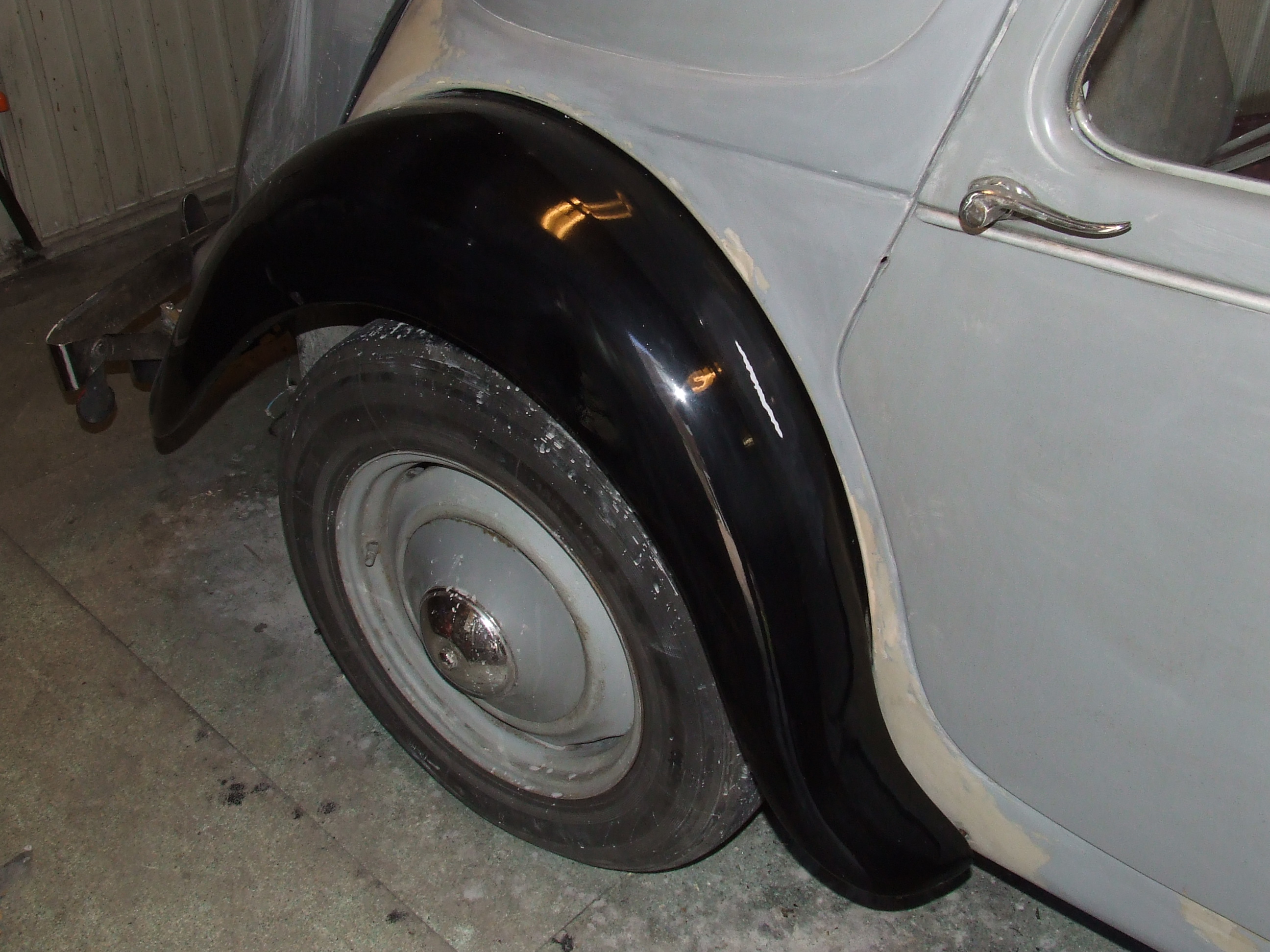
Fenders completely repaired and painted black
Body panels repainted in original color
Seat and door upholstery panels bought, to be installed after all rust and headlining is removed
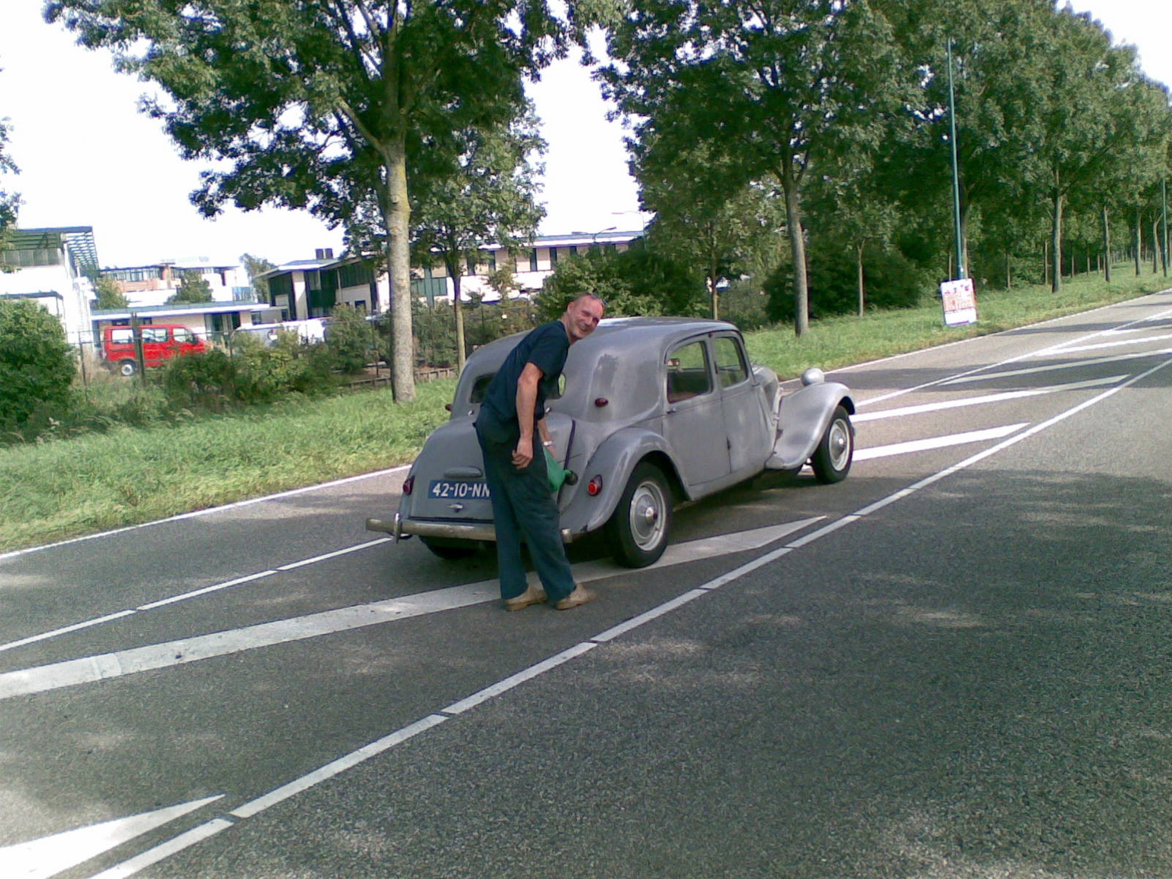
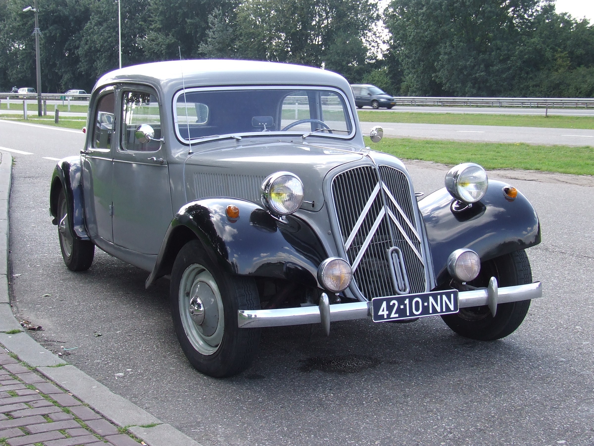
Ready to drive – All done but still work to do on the trim and fenders. In this picture the holes in the mudguards are provisionally closed.
In this state I drove a few times 200 kilometers without any problems.
Total of 2000 kilometers driven until April 2007.
From the beginning of April 2007 I started to refurbish the exterior. See the following pictures.
Next to that some work needs to be done on the brakes because the return movement is too stiff which causes the brakes to get hot in traffic.
Also the front wheel bearings need to be adjusted because there is some wheel play.
The mounted thermostat does its job well but because warm water enters the radiator in one go the final level in the radiator is about 5 centimeters below the top edge. This turns out to be sufficient in practice. Despite the thermostat, the radiator roll cap has proven to be necessary during the winter.
PS: In the meantime 1 small hole has been drilled in the thermostat to keep the circulation always going a bit.
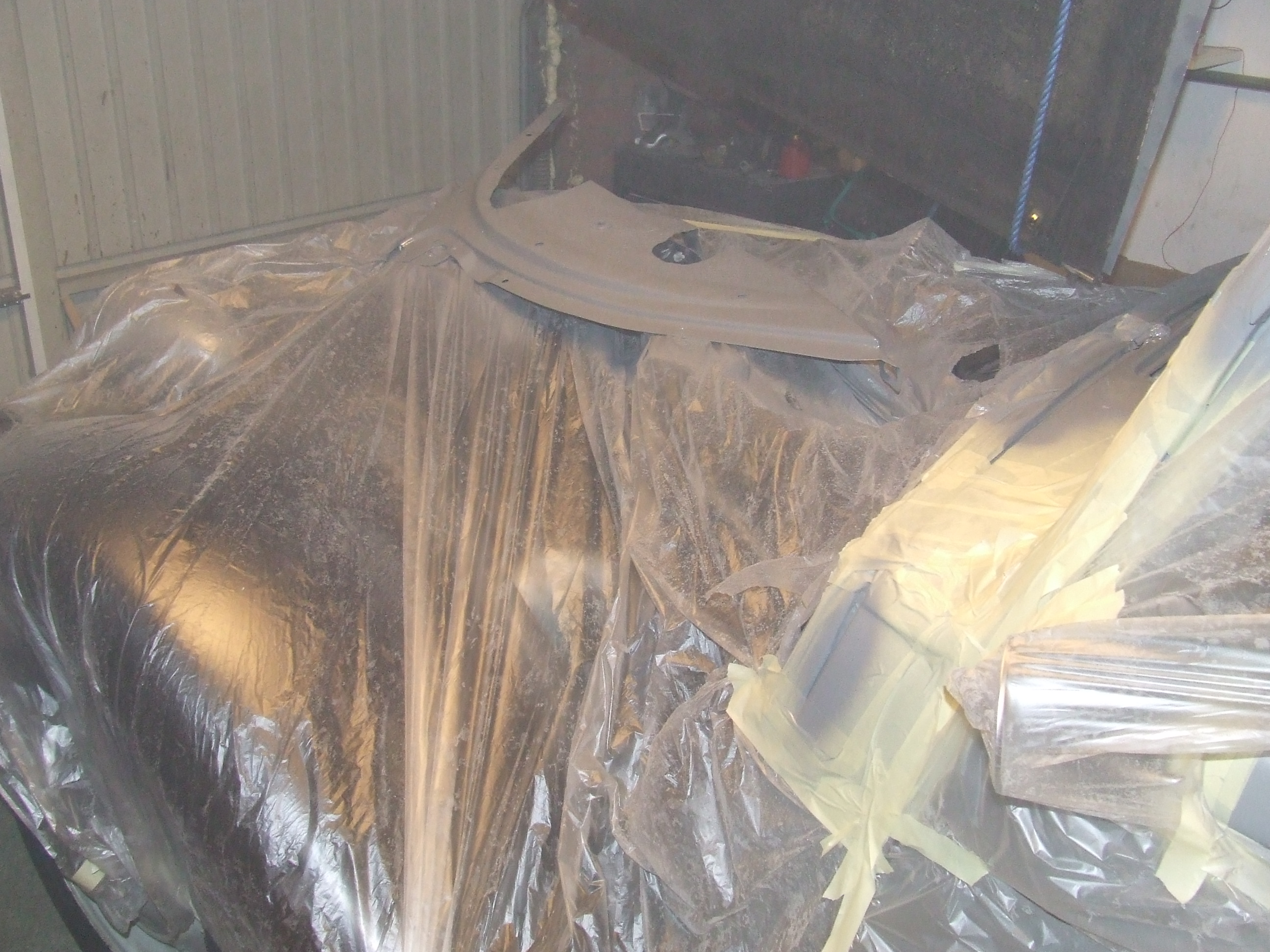
The welding and spraying work
April 10 to 30, 2007:
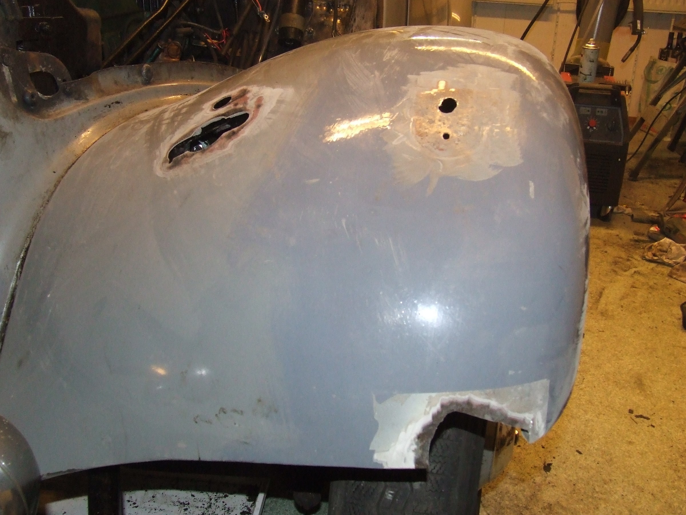
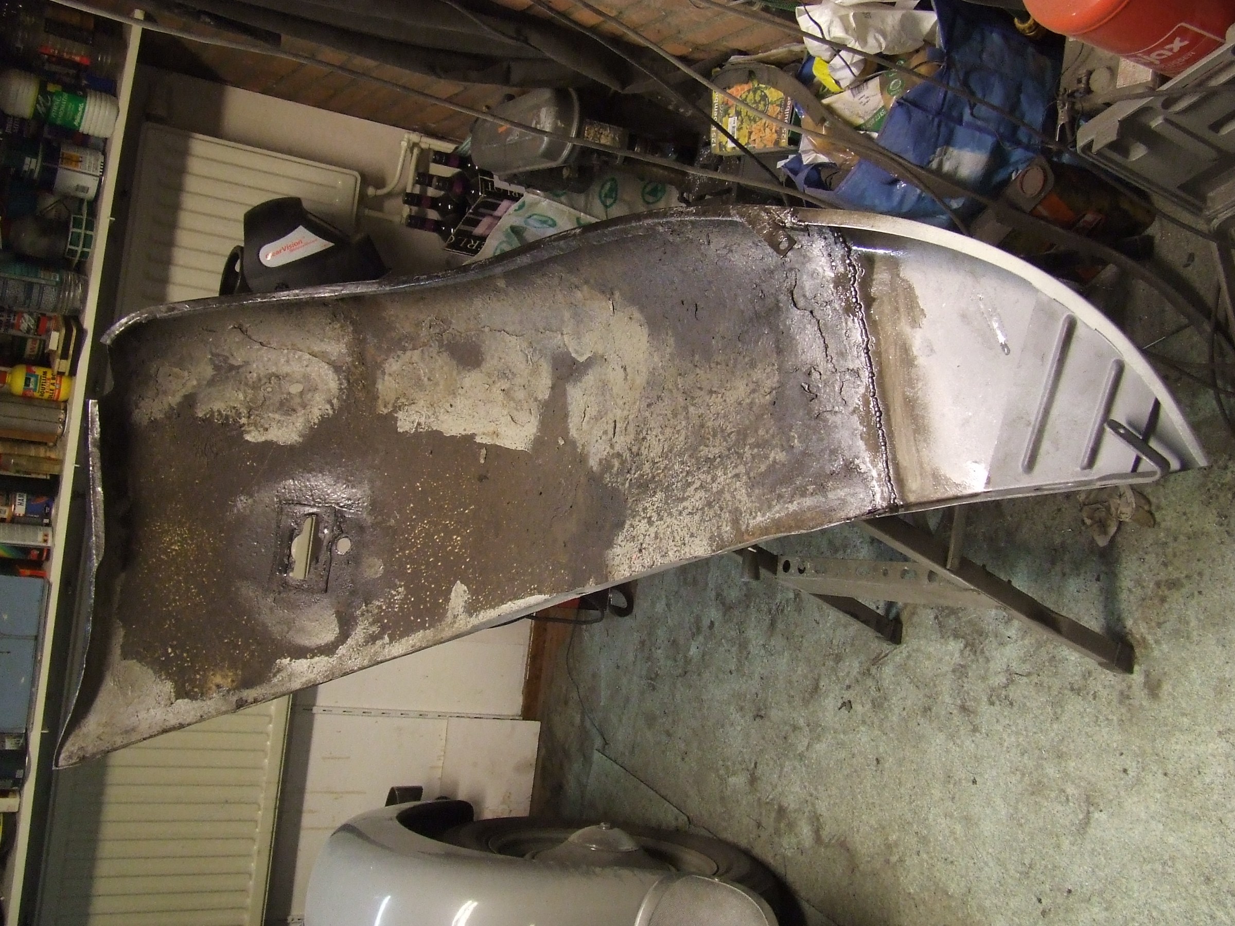
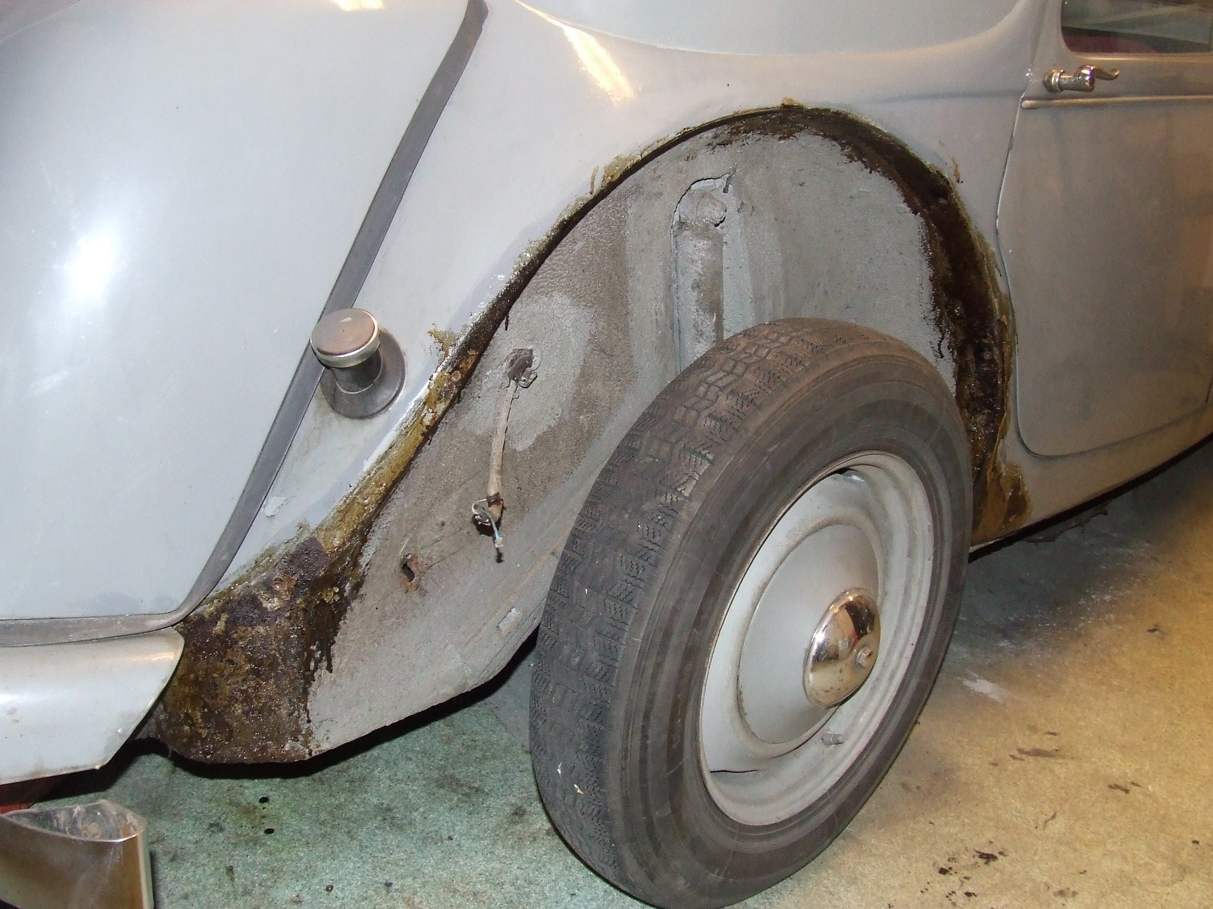
Fenders disassembled.
First we stripped everything as much as possible, applied Fertan, let it work and rinsed it off.
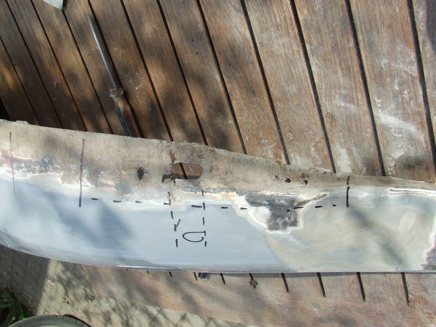
Around the holes made bare. Cut out the bad parts.
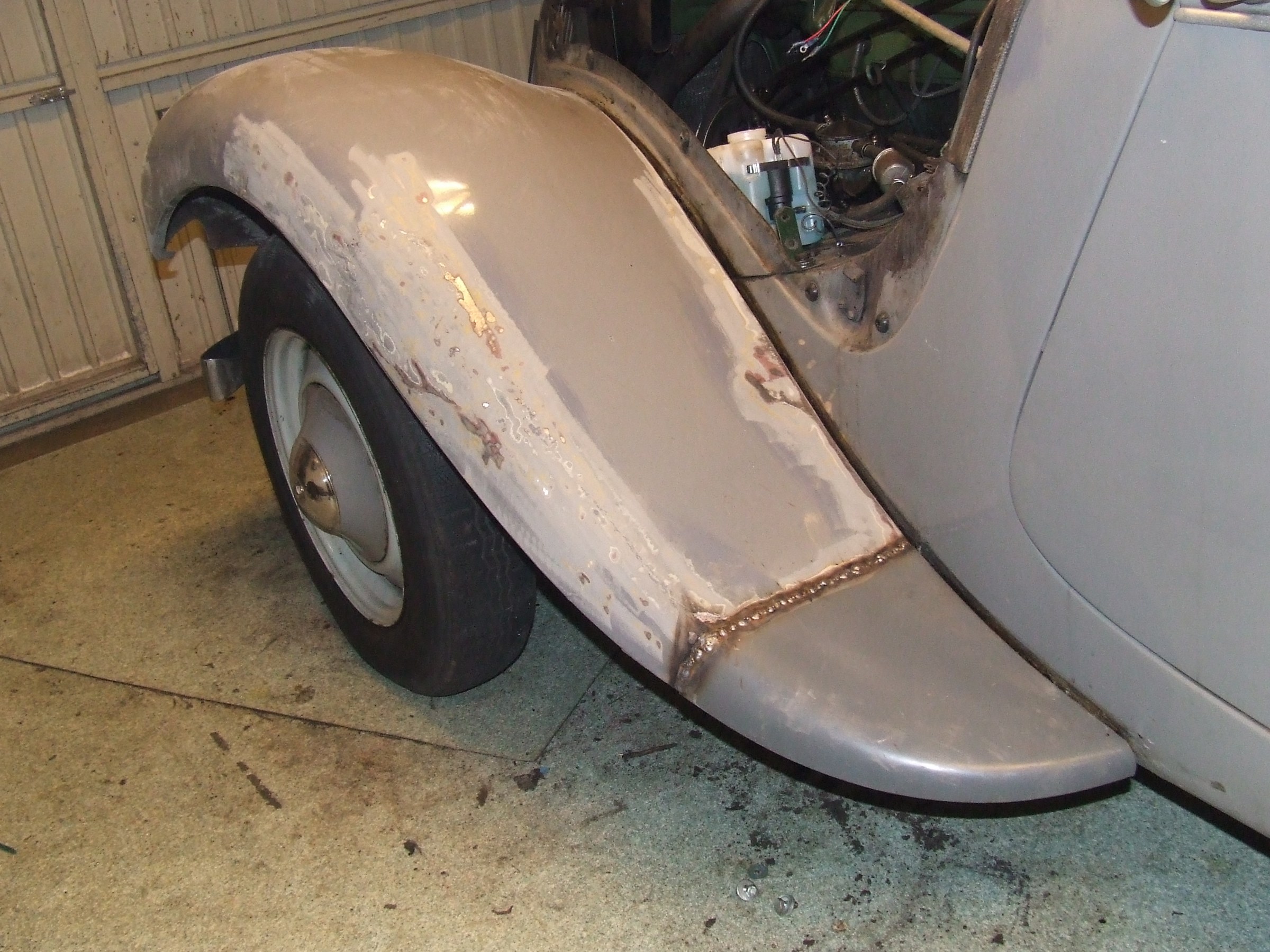
Welded in 1 replacement part (point left front mudguard)
For all parts to be replaced, beaten up and welded in place suitable body steel of 1.5 mm (MIG)
Grinded where necessary
Sprayed with INOX, inside and outside against rusting of the welding
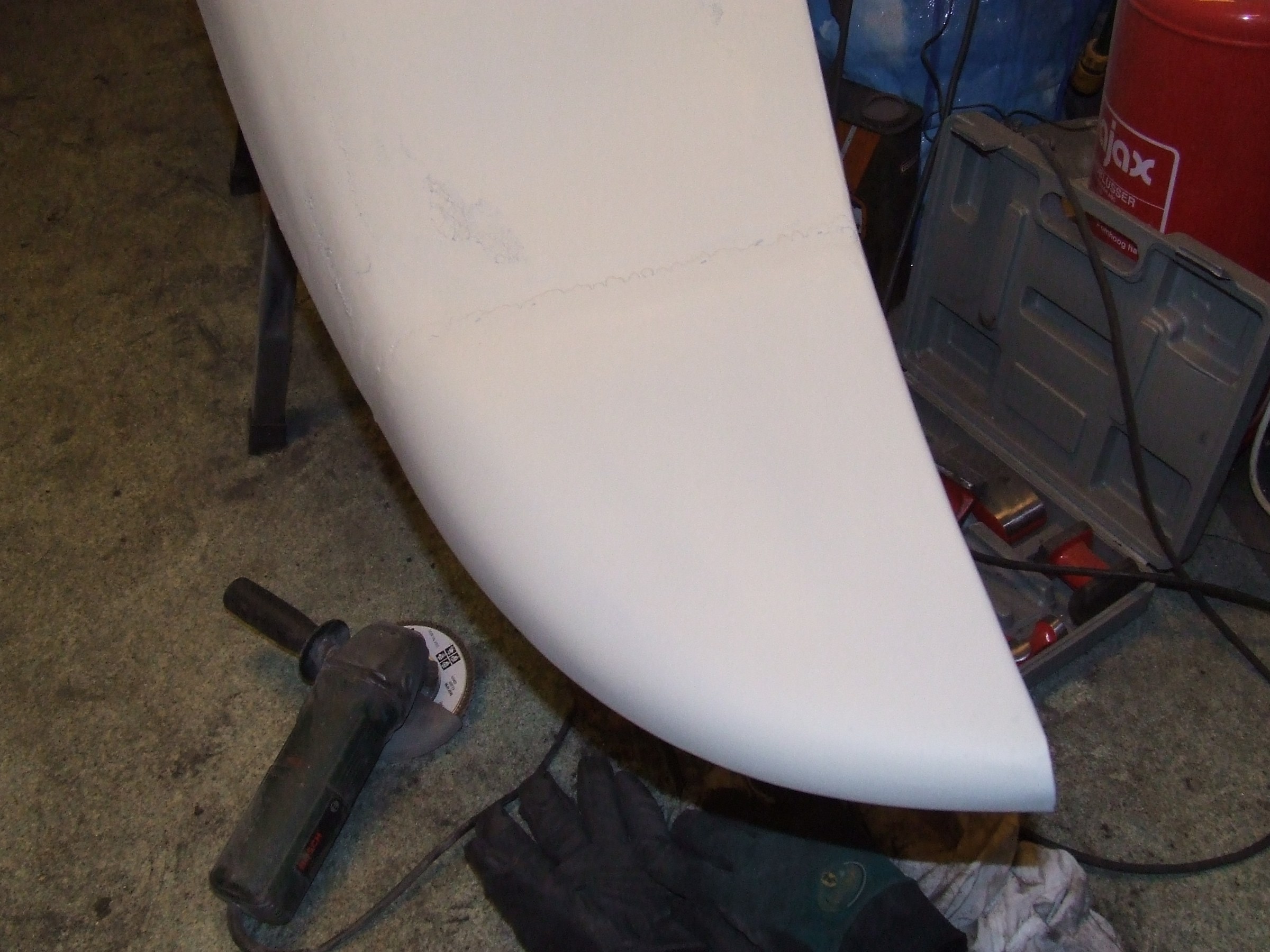
Flameproofed with 2K, sanded in shape with 120 and 180
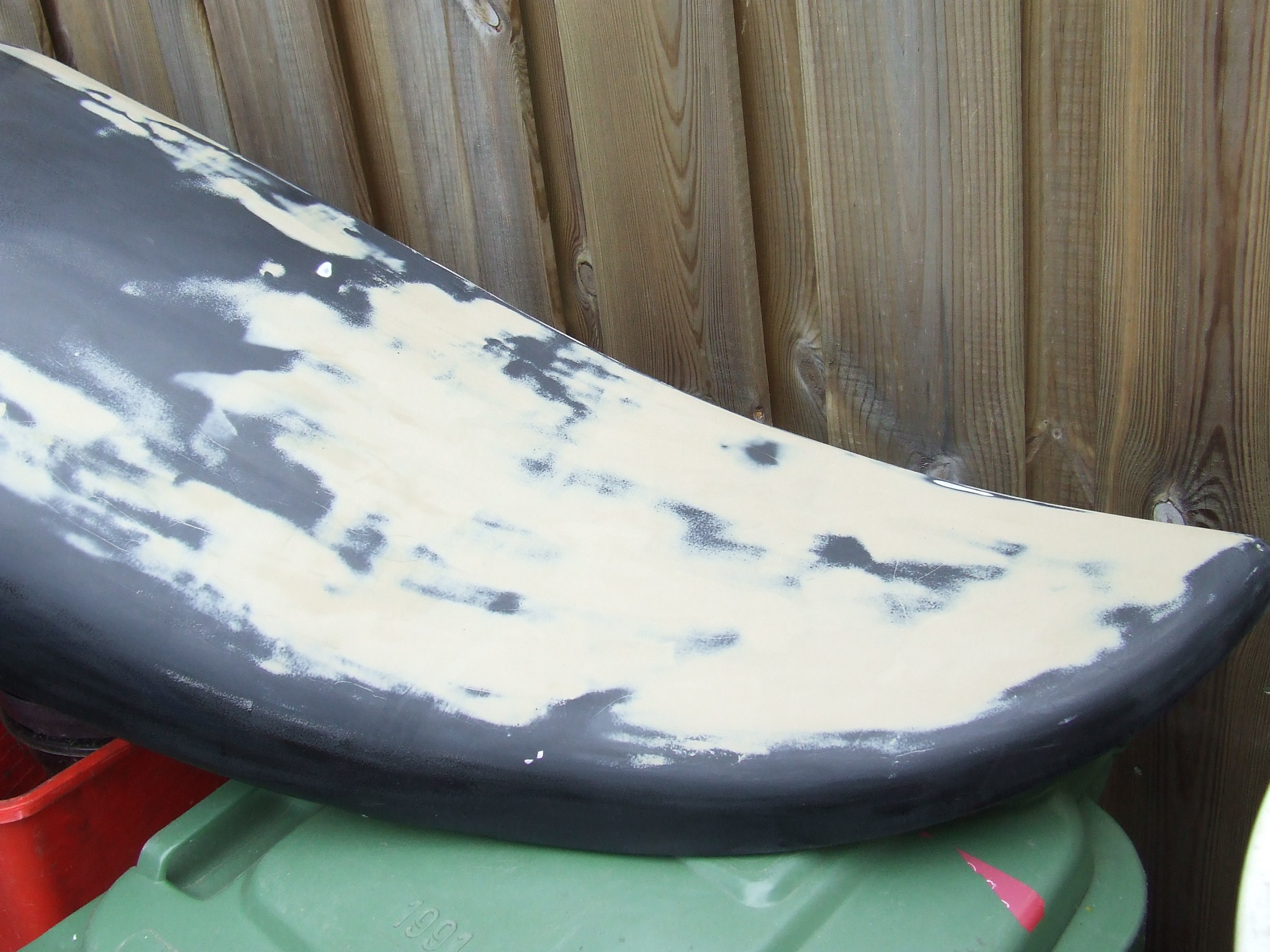
Spray putty
Fine putty, sanded flat with 600 and 800
Black 2K lacquer on top.
Fenders mounted with new piping.
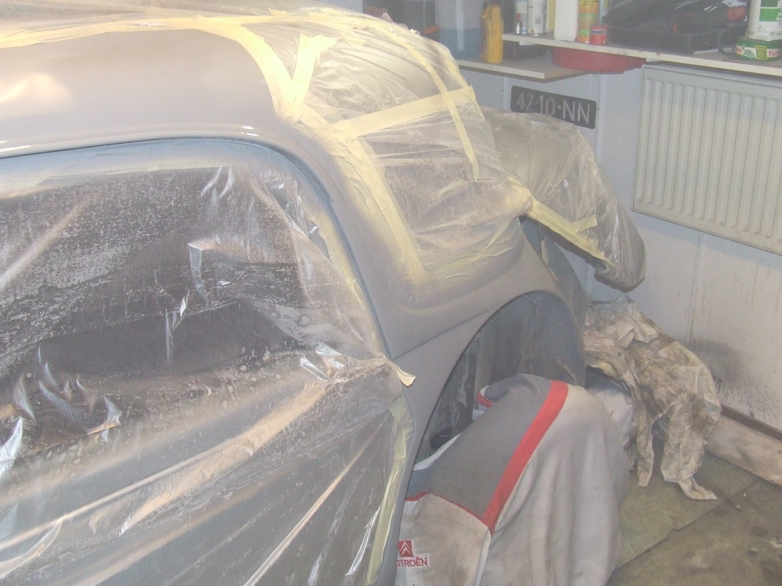
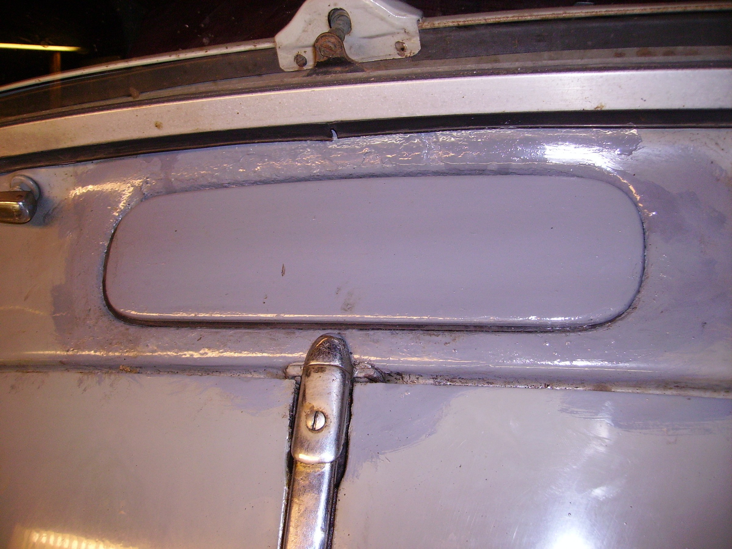
After the fenders, it’s the body’s turn.
All rusted spots were cleaned, Fertan applied.
Welded where necessary and then ground smooth.
Then filler, sanding, filler, sanding, etcetera.
Spray putty on it and then the (most) original color over it.
Reassemble everything, polish it and then proudly drive around!
That all sounds simple, but it took about 3 months…
July 2007: After the paint job on the body it was enough for a while.
The trunk, hood and grill will come next time.
All rust on grill, hood and trunk is preserved and the bare spots are painted as a temporary measure.
The headlight supports have been replaced by aluminum polished supports.
After painting the trunk, hood and grill, it will be the turn of the interior replacement….Probably in winter 2007/2008.
After the purchase, the TA’s gearbox turned out to be defective. 2 teeth were missing from the 2nd gear. Later I (fortunately) discovered both teeth in the gearbox’s oil sump.
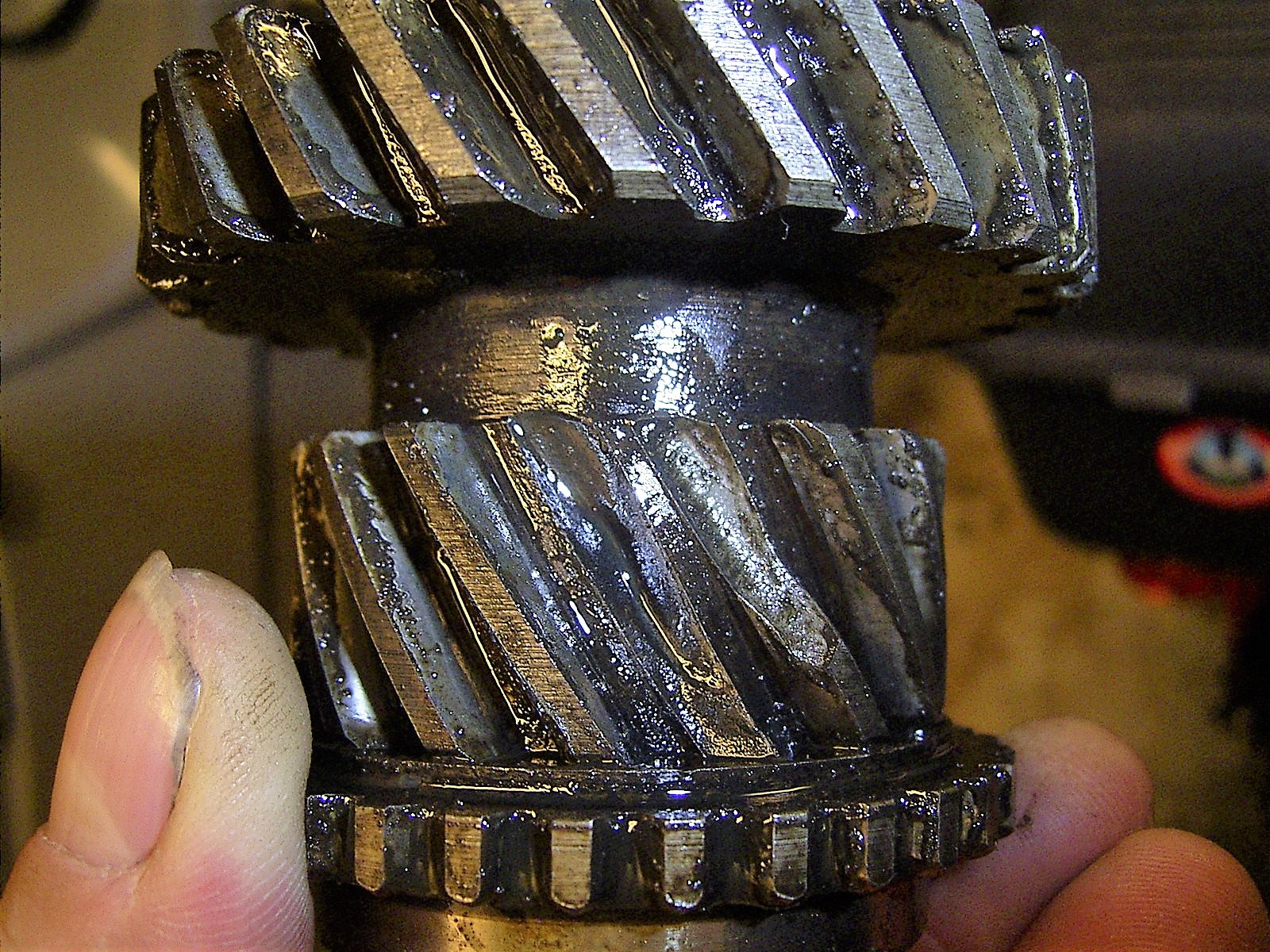
This second gear is the most vulnerable gear, especially because people often try to drag a TA in 2nd gear.
Or they try to get the engine loose by force dragging it in 2nd gear.
Fortunately I was able to buy a NOS gear via the TA club warehouse and after an evening of reading the garage manual I dismantled and reassembled it.
Easy to do most of this myself. With help from my brother in his garage, to set the Timken bearings at the correct tension and adjust the play of the differential.
Also mounted new oil seals.
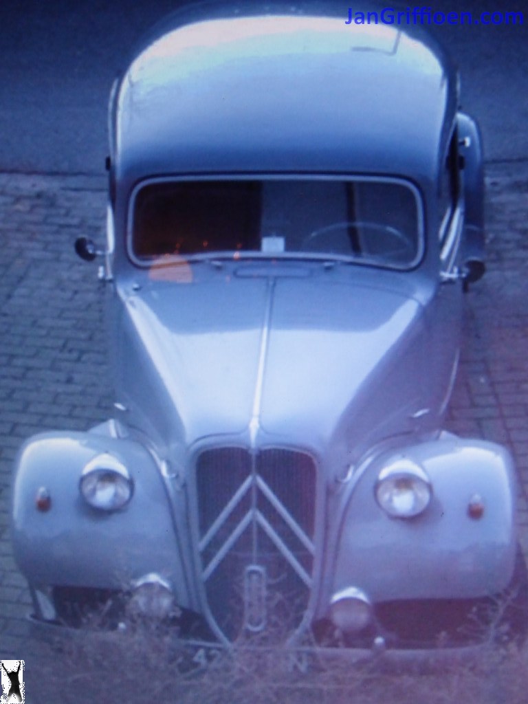
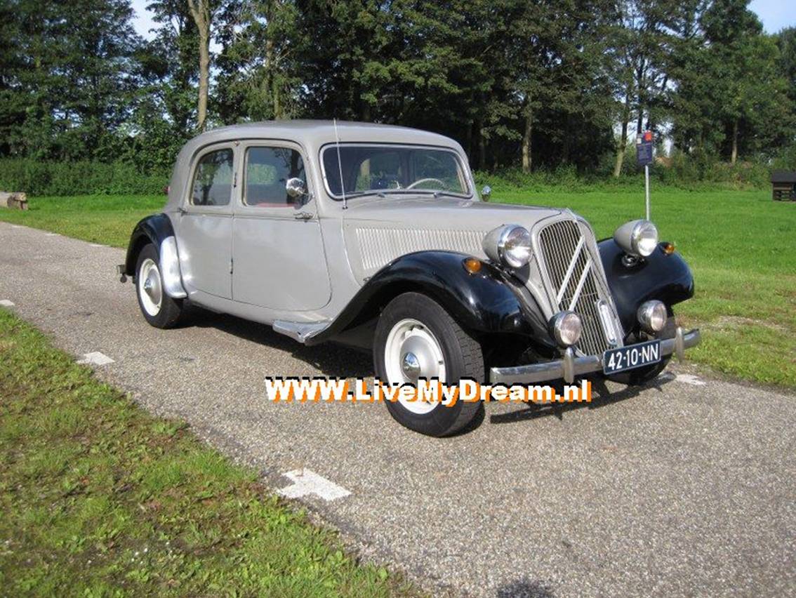
After the sale was completed for Eur2000,= I went to pick up the Citroën Traction Avant 11BN (built 1955) in Leiden with the rented car trailer.
The 3 below pictures are the seller’s ones from Marktplaats.nl:
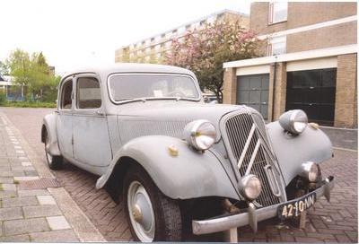
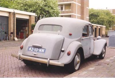
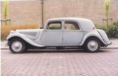
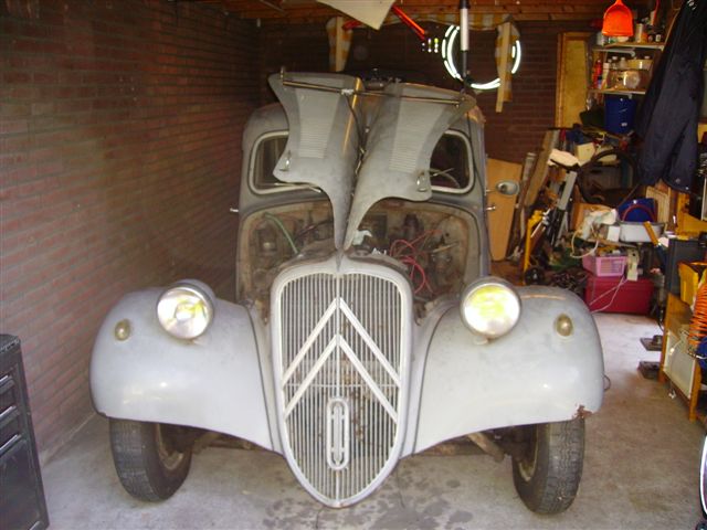
At home:
After the first inspection it turned out that nothing actually worked.
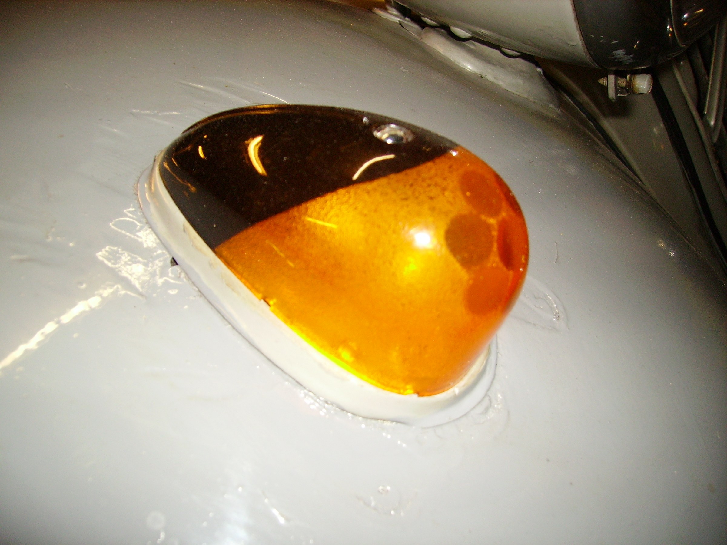
The engine was stuck, there was water in the oil, the gearbox was broken, holes in the fenders, headlight mirrors rotten, rear light lenses broken, gas tank leaking, exhaust rotted, tires on, front bumper was rotted off and so on.
But the bottom, side, roof and body were rock solid.
Read more: FIRST MOT