DOWNLOAD CNC_controller_box_6_parts_V2_C)JANTEC.NL_20251102
Please donate $1 to my paypal account if you use my original designs -)
THE CNC CONTROL BOX

Download the CNC controller box design file via the above link in 1 piece which will take around a day or more to print.
The CNC box design is available in 6 separate design STL parts that interlock very well and will have to be glued and (if you so desire-screwed) together.
The box is also available for DUET3 HERE
THE ENTIRE CNC CONTROLLER BOX AS 1 STL FILE:
THE ENTIRE CNC CDY CONTROLLER BOX AS 1 STL FILE: 
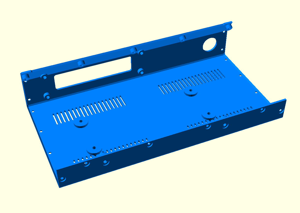
THE CDY BOTTOM PANEL:
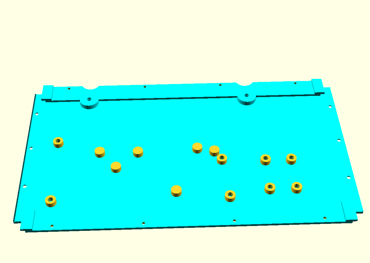
THE ’empty’ BOTTOM PANEL:
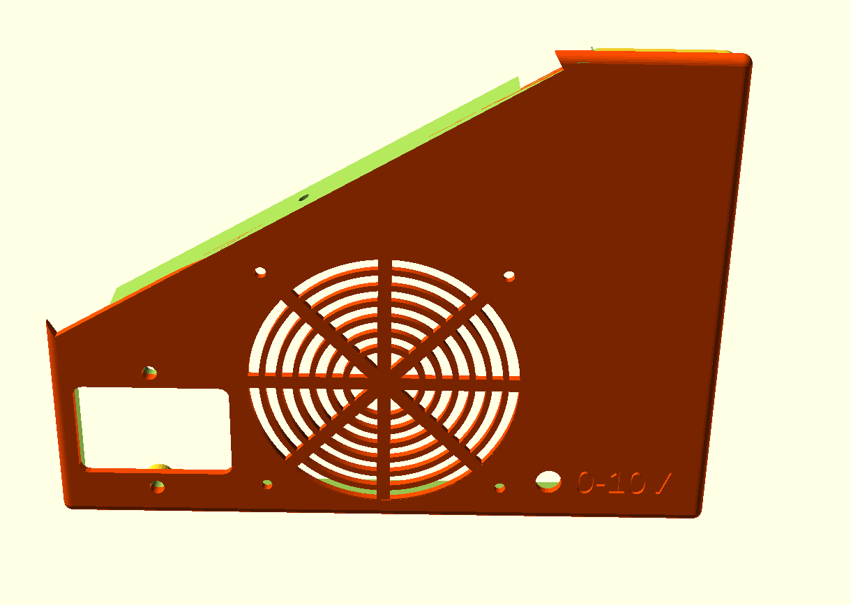
THE LEFT PANEL:
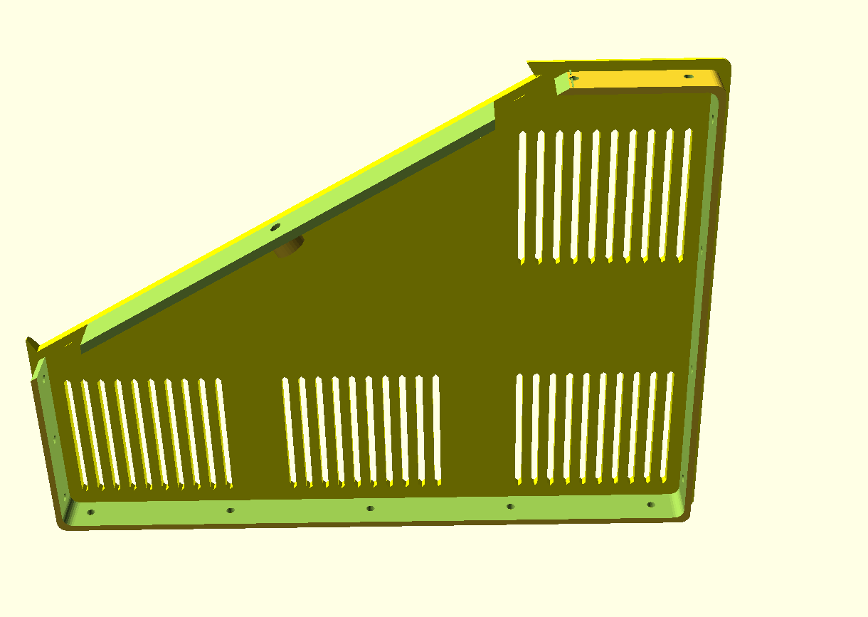
THE RIGHT PANEL:
THE FRONT PANEL:
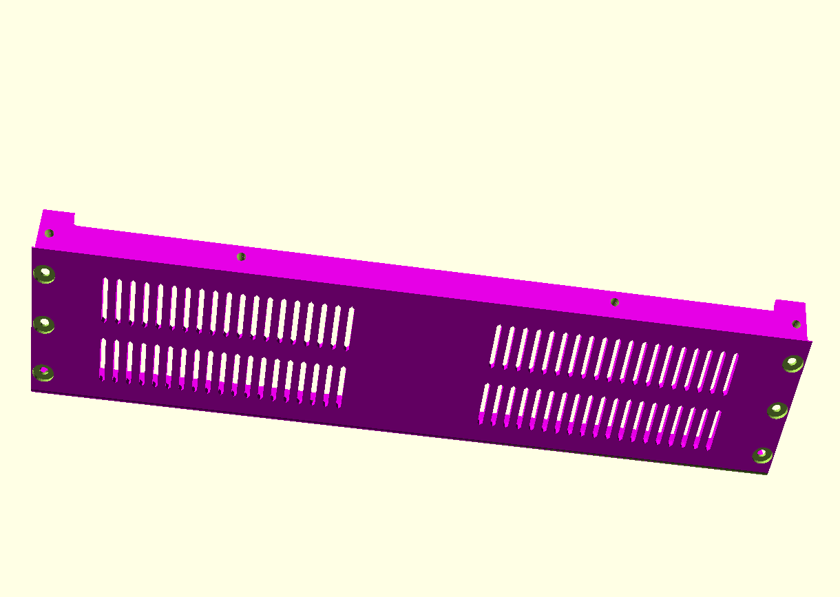
THE REAR/TOP PANEL:
THE TILTED TOP PANEL:
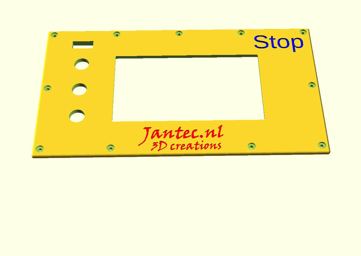
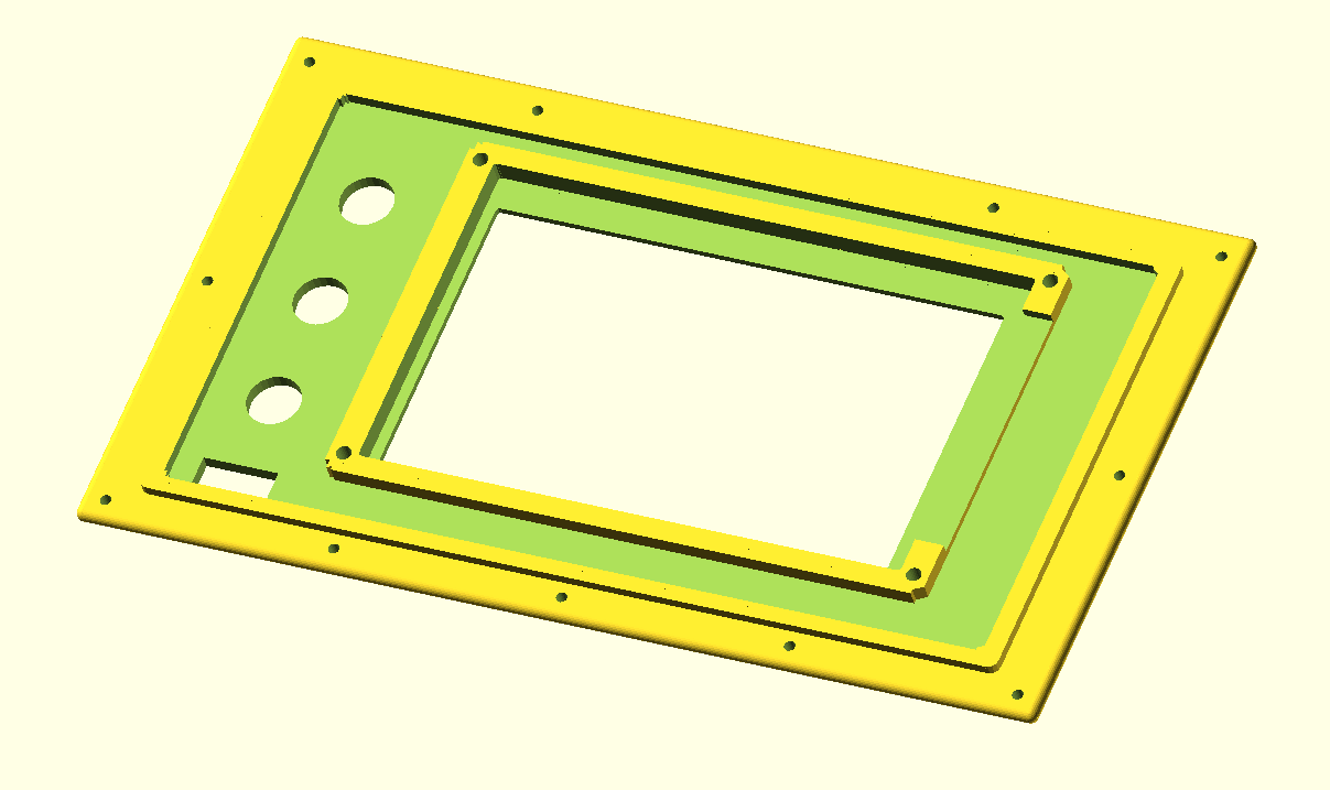

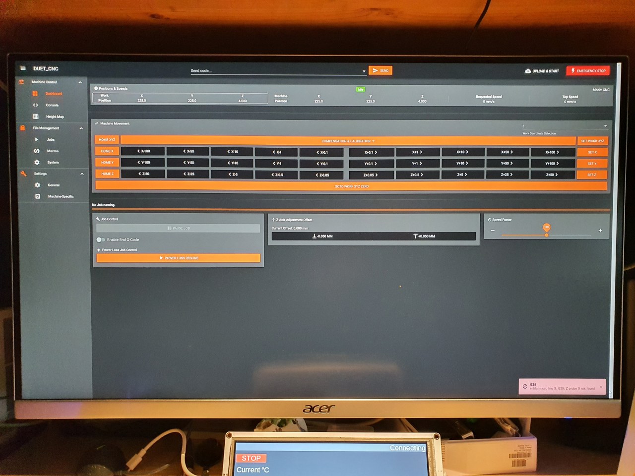
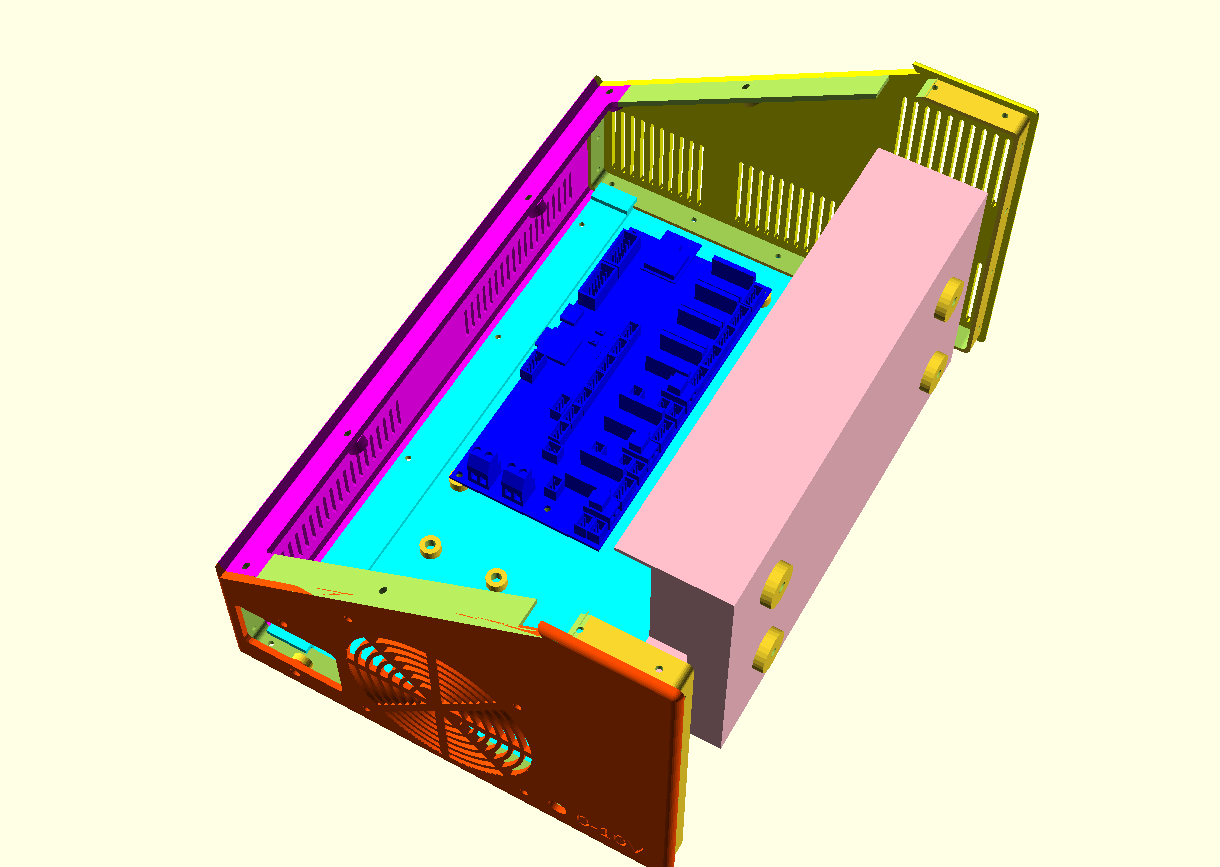
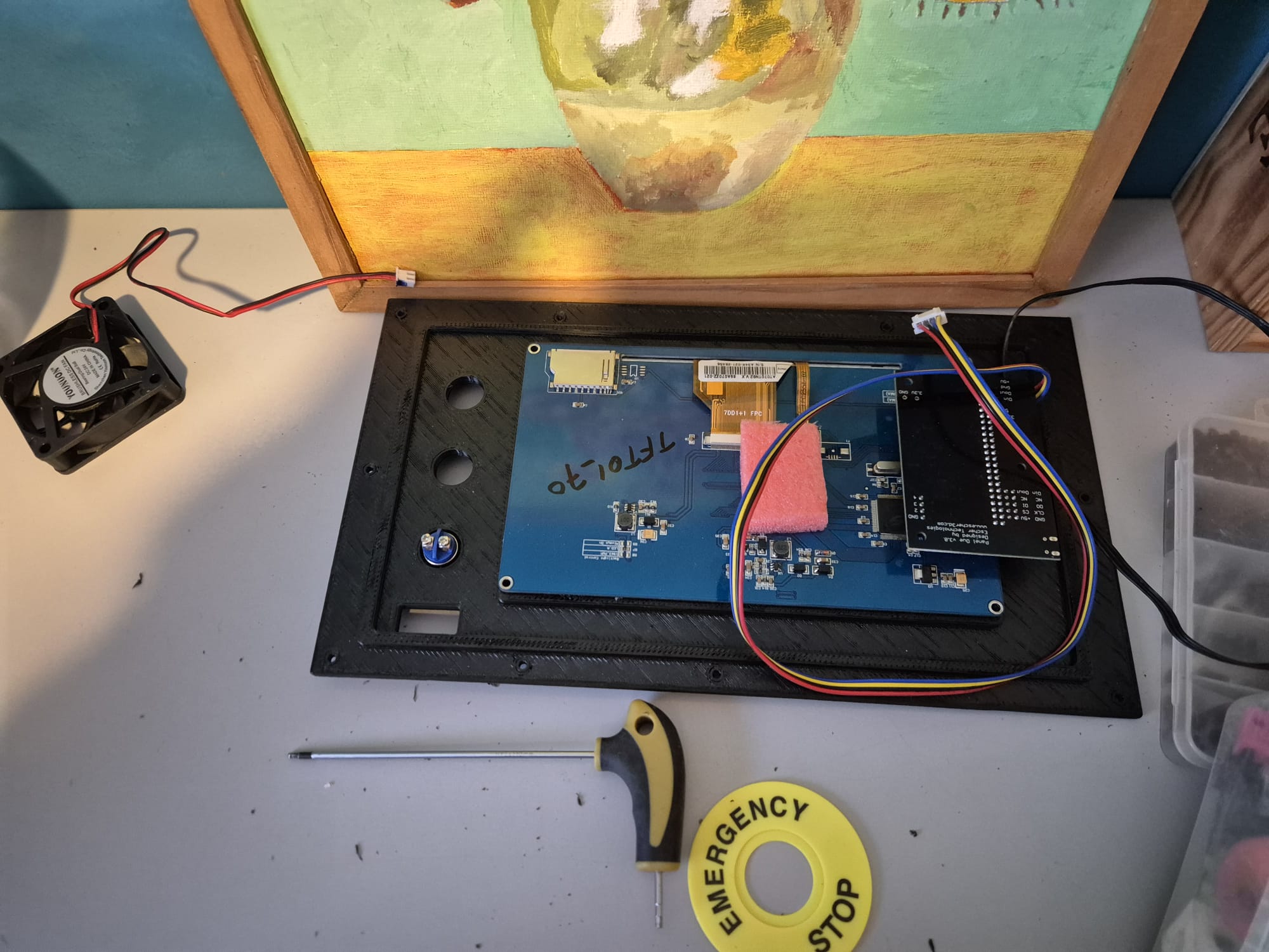
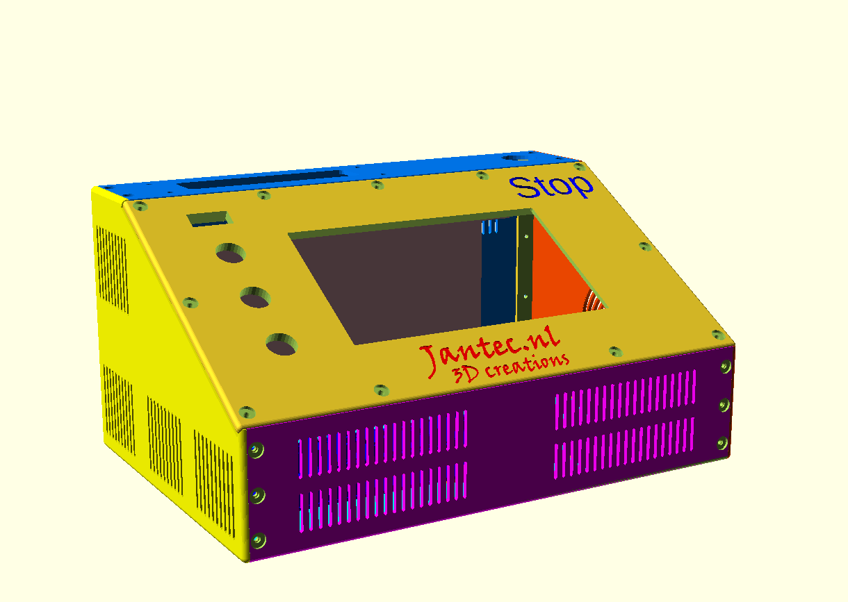
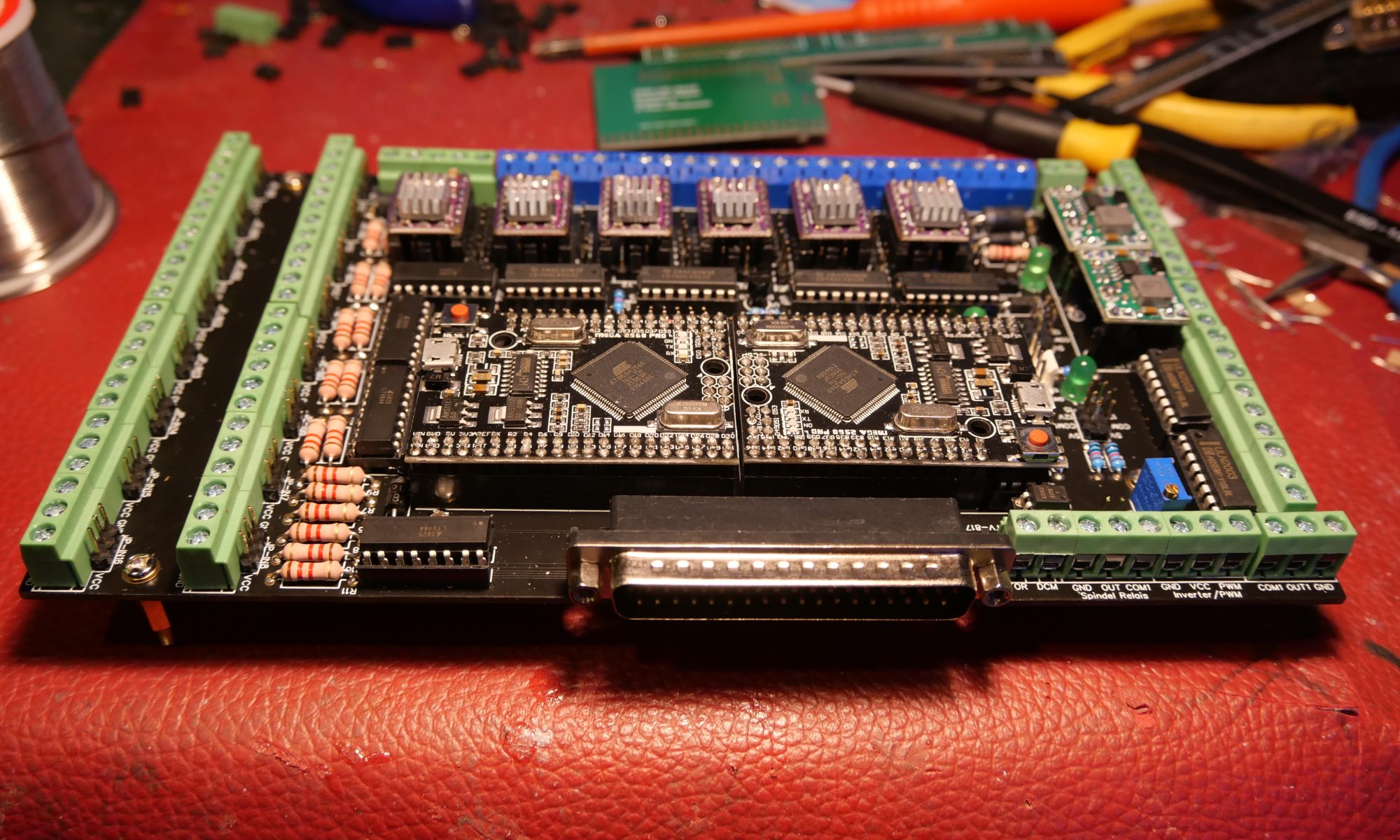
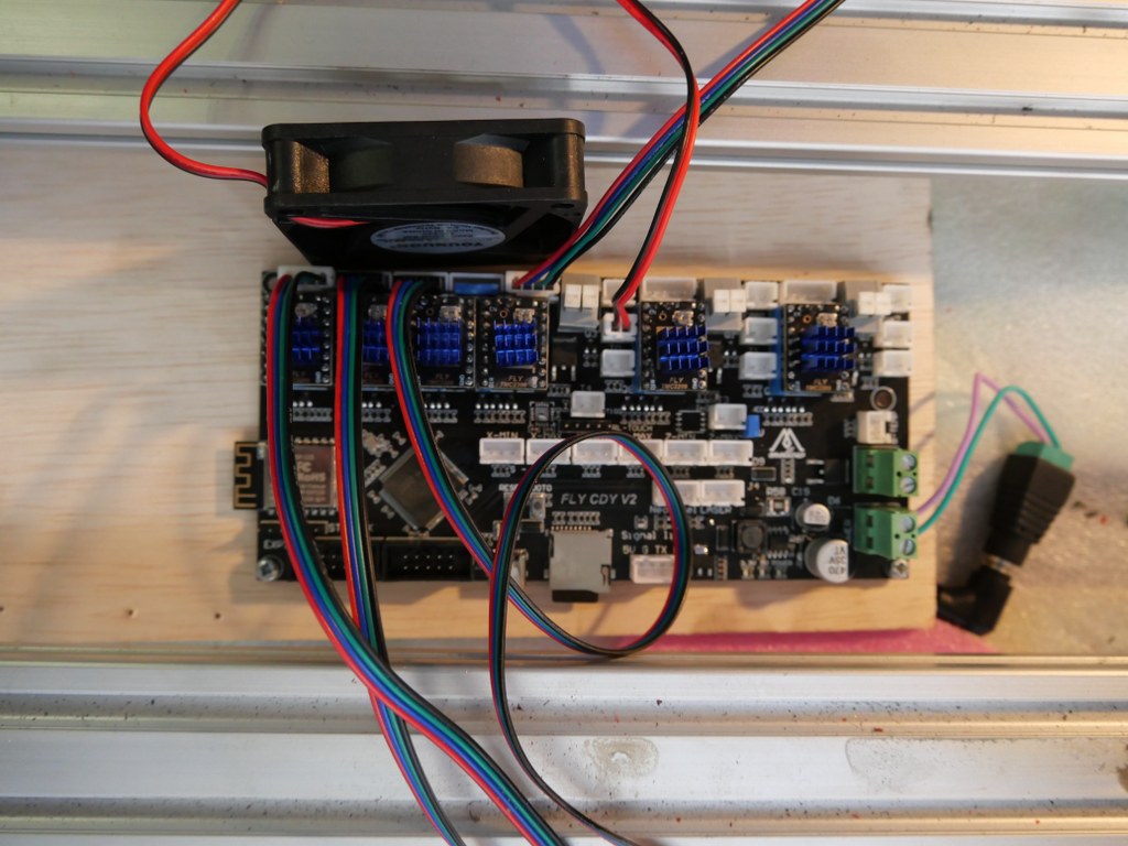
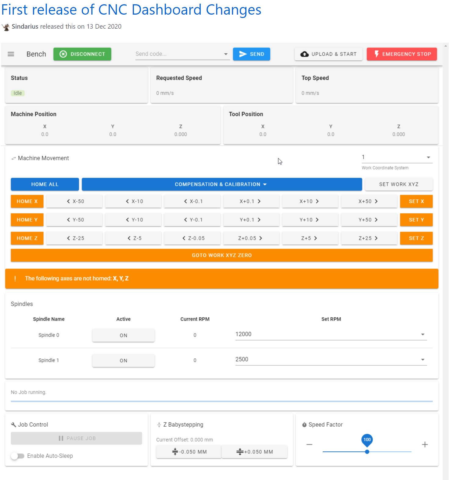
The tilted top panel houses a FysetC Duepanel 7 inch LCD module that interconnects to the FlyCDY2 or 3 ( and will also fit to the Duet3, obviously).
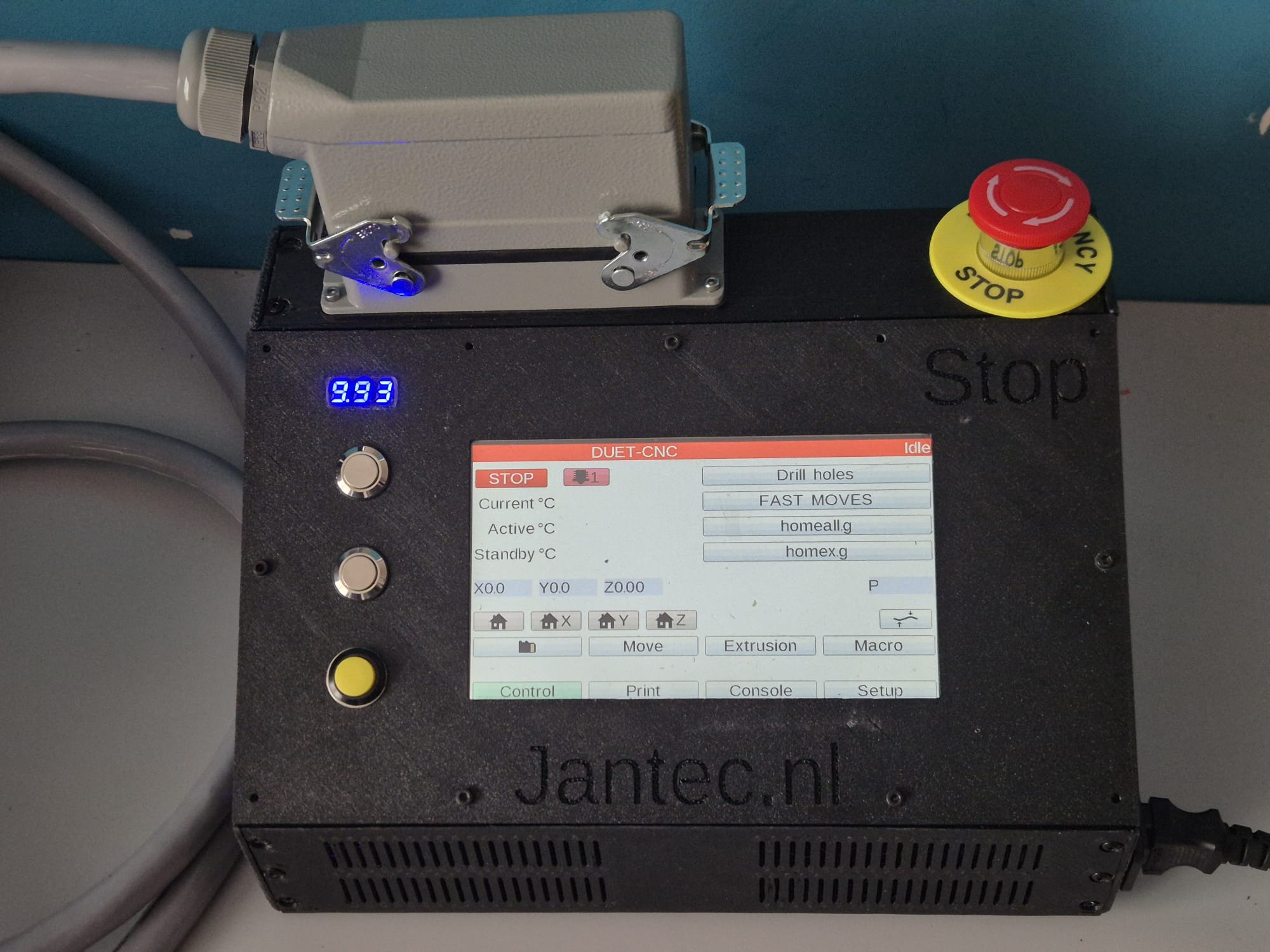
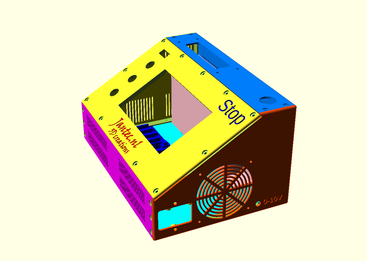
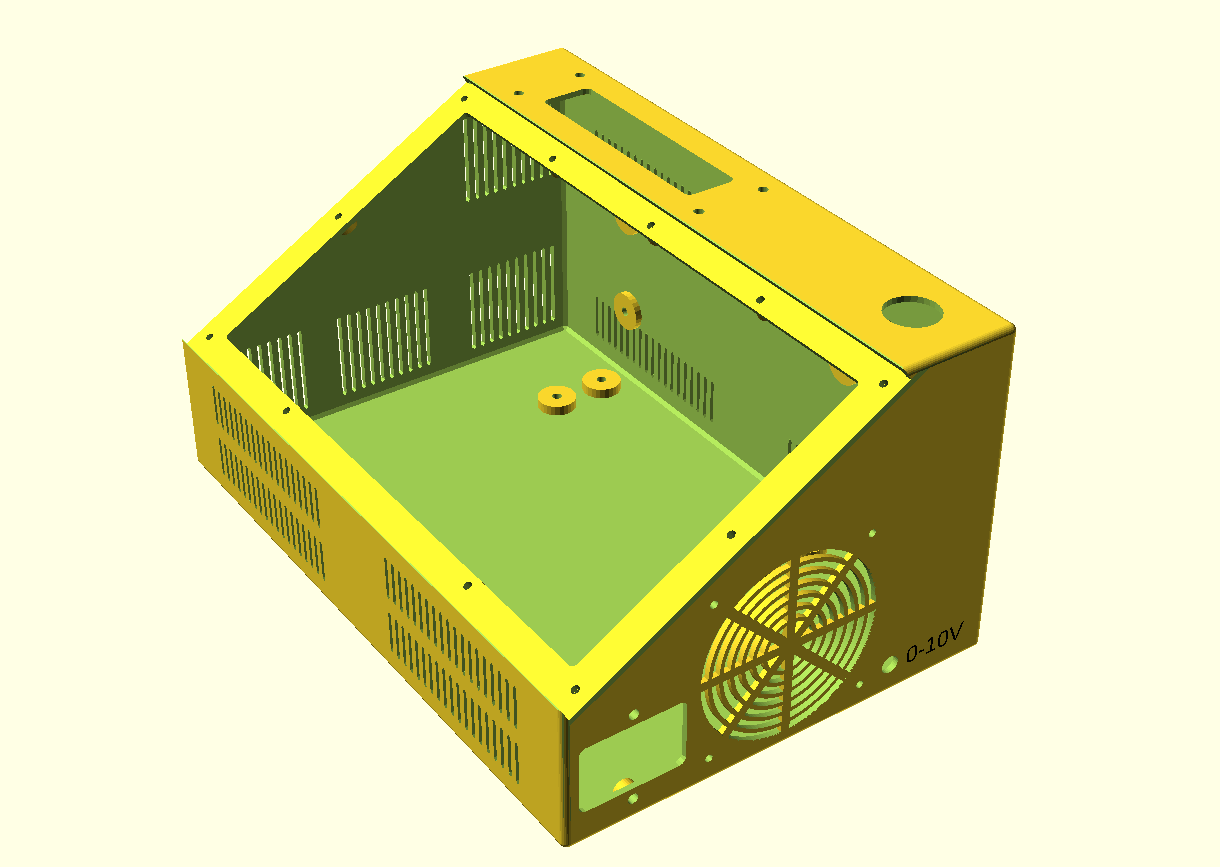
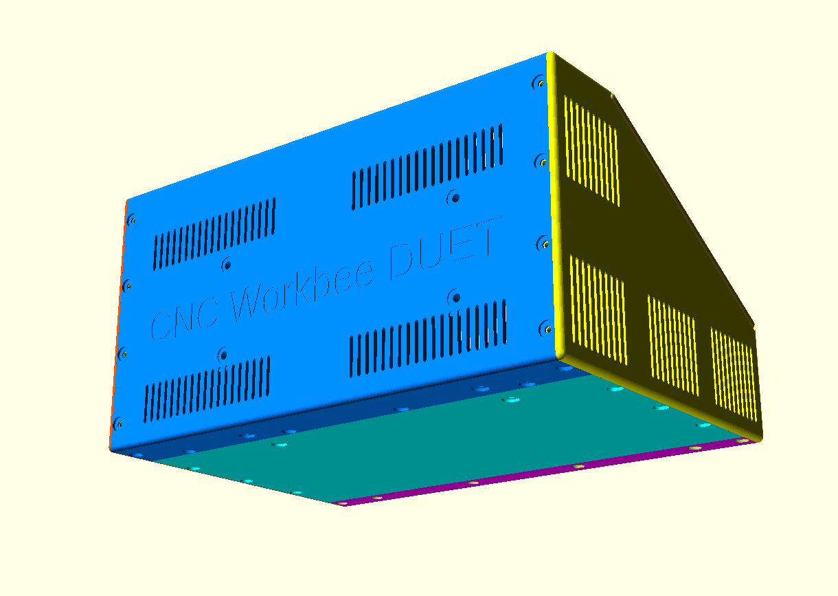
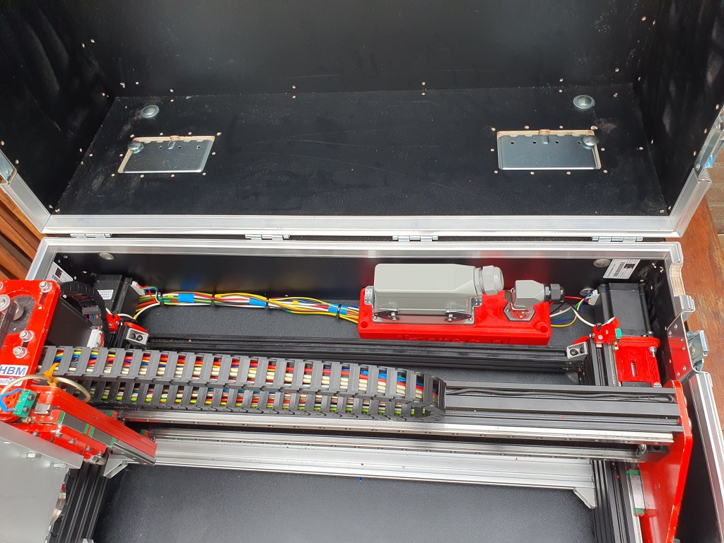
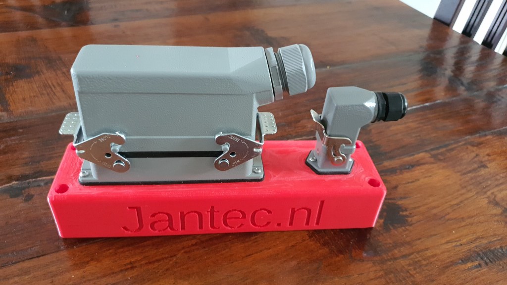
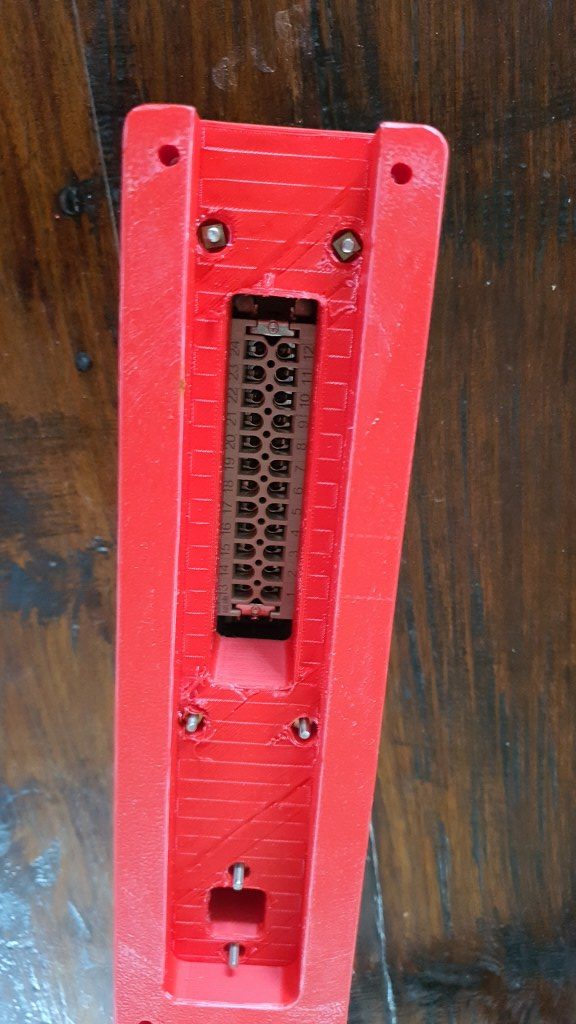
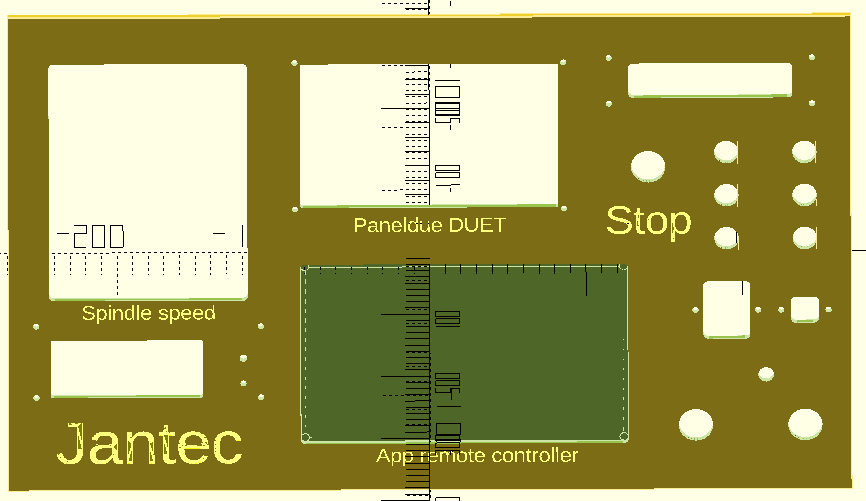
The box and panel also include holes for a 24-pins multiconnector on top, a panic button on top, an 80mm fan unit, a filtered power inlet unit (in my case, for 230V Europe standard) and 3 button holes on the tilted panel, as well as a small hole for a voltage reading unit. Any other required holes can best be done after printing. Just with normal tools, by using painters tape first to cause minimal collateral damage to the case.
All parts that can be screwed on or-in, can utilize M3 threaded inserts at the mounting points inside. The holes are supporting these. This is not done for thePSU (obviously, the M4 mounting bolts run through the case). The fan is mounted with M3 bolts from the outside through the case and secured with nuts against the fan’s body.
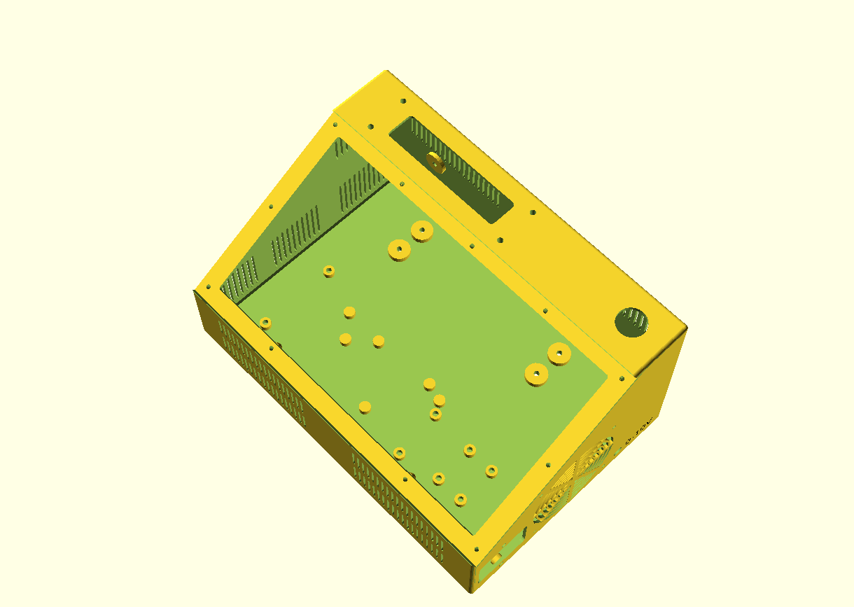
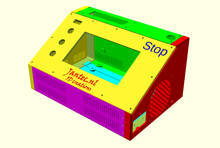
CNC CONTROL BOX DESIGN, PRINTABLE IN 6 INTERLOCKING PARTS
HOW TO PRINT
I always print tools and toolcases in ABS at 260-270 degrees, 100% fan and 100% infill. . Use minimal support of about 85% for these parts but always use maximal adhesion on the OUTSIDE only!
Also, set Cura to a shrinkage correction of 100.7%, due to ABS black shrinkage of 2.2 mm on the long side of the box. (The xSize should be 295 and this was measured 292.9 after being printed as full box)
For constructing the box from 4 individually printed parts, first connect the bottom parts without glue. Then, attach both the sides and screw in the front panel. Then, where needed file or sand off ledges so it all fits properly. Then, remount it all and let the glue find its way between the connecting overlapping ledges that connect the parts.
Print all parts with the vent openings down.
All parts will print best with support 85% AND adhesion outside only ON.
Print support with 85% angle support everywhere at 5%, so the M3threaded bus-supports will be printed well.
PRINT ORIENTATION EXAMPLE (Cura, VORON 2.4-600)
Please be aware that the 6-part design is developed with printing in mind, so the horizontal printing orientation as shown above is the only way to avoid overhangs in the interlocking ledges. This also goes for individual printing of each part.
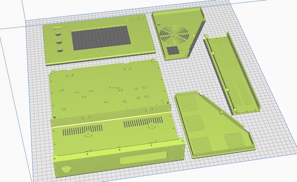
I print this with an 0.8 mm nozzle at 0.4-0.6 mm layer height and a full print-run of all items at once still takes 1 1/2 day, at 100mms speed.
Therefore, I am now printing each part individually so I can manage it a lot better. No fun when you run suddenly out of filament..-)
Please donate $1 to my paypal account if you use my original designs -)
DOWNLOAD CNC_controller_box_6_parts_V2_C)JANTEC.NL_20251102
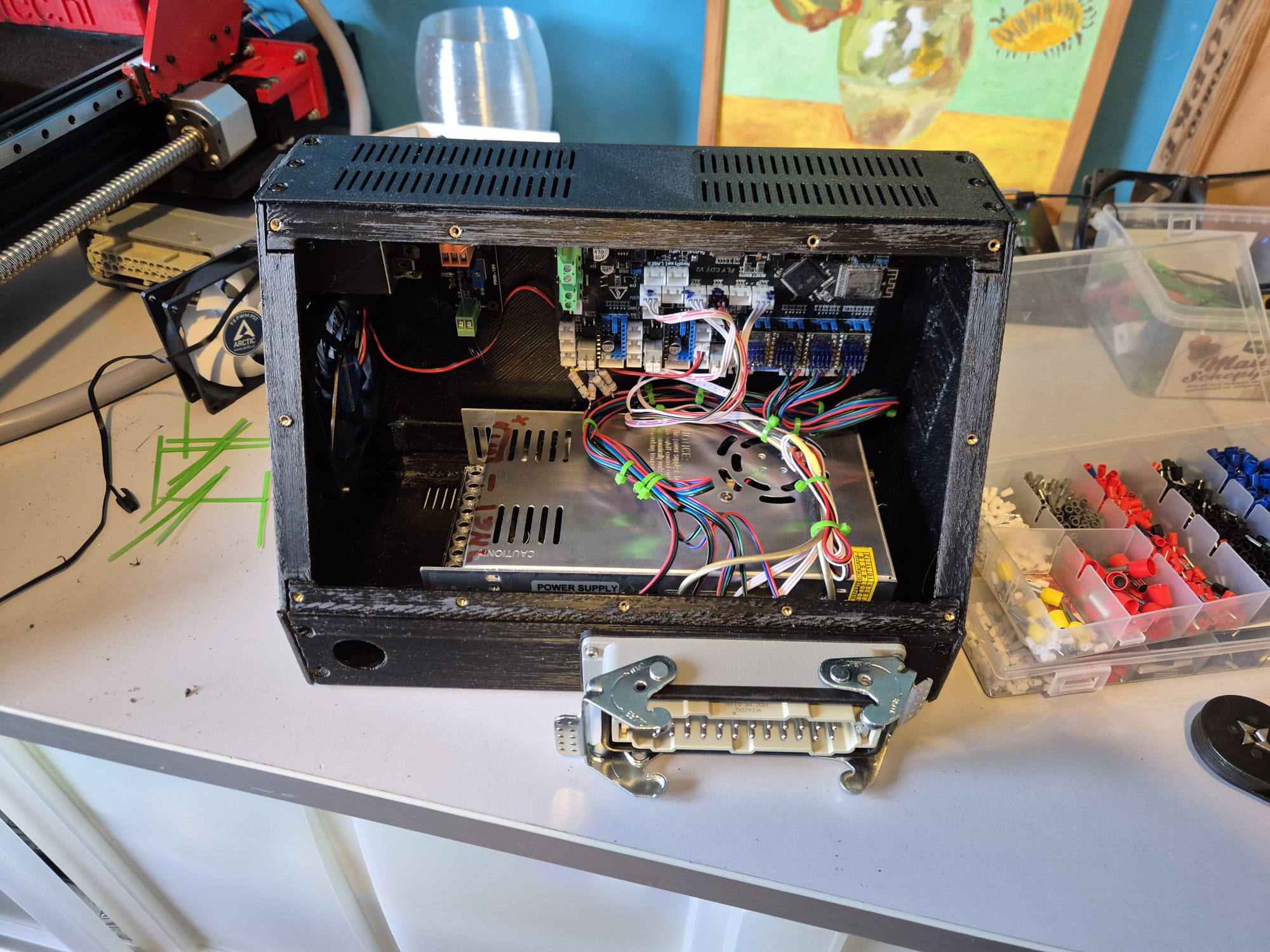
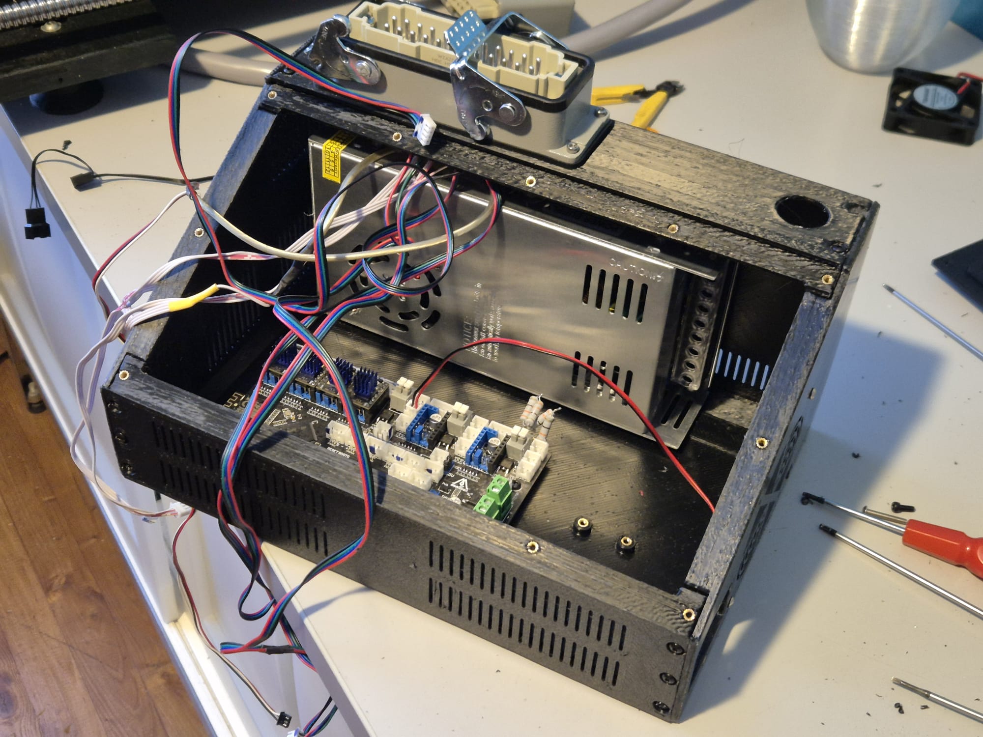
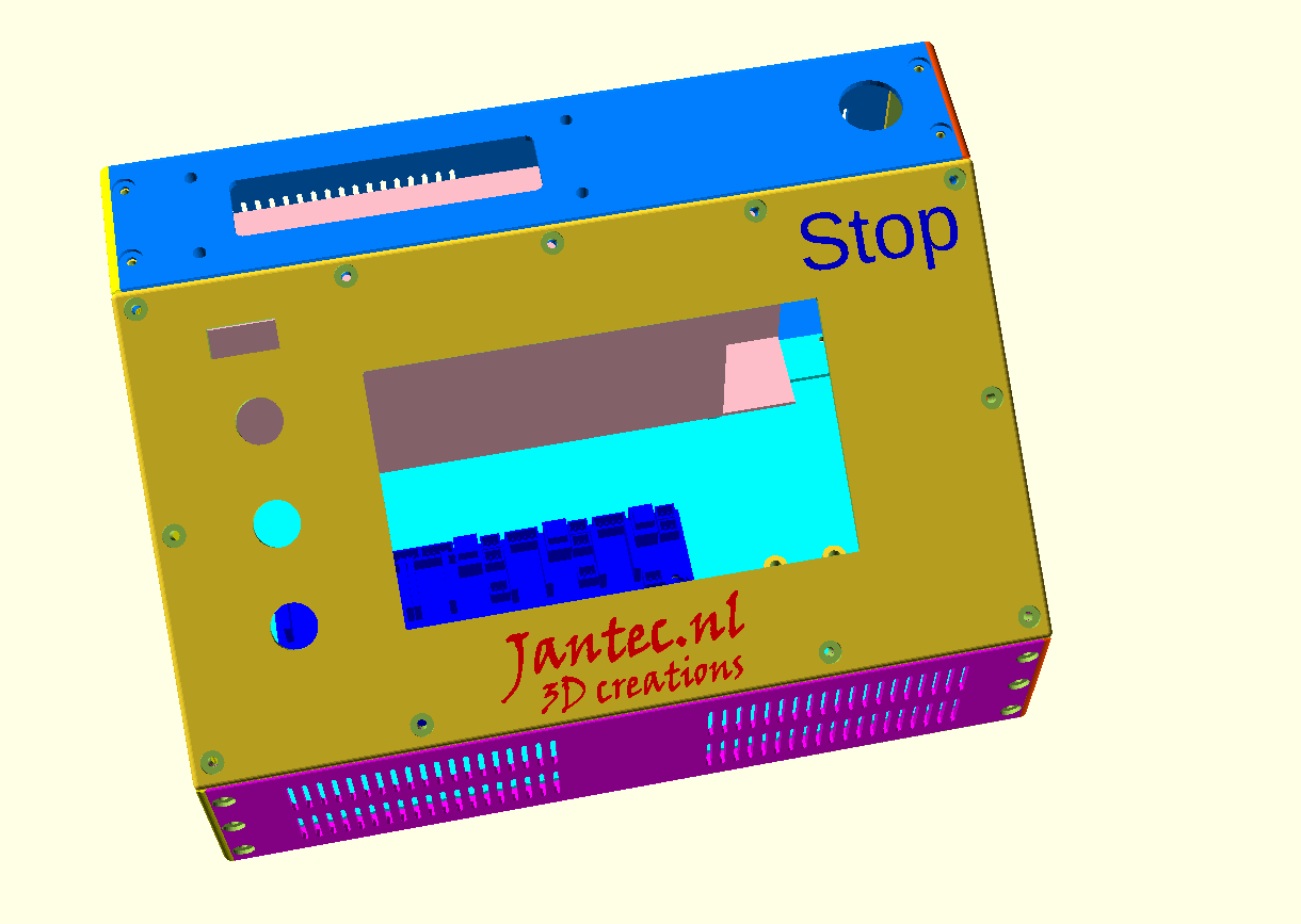
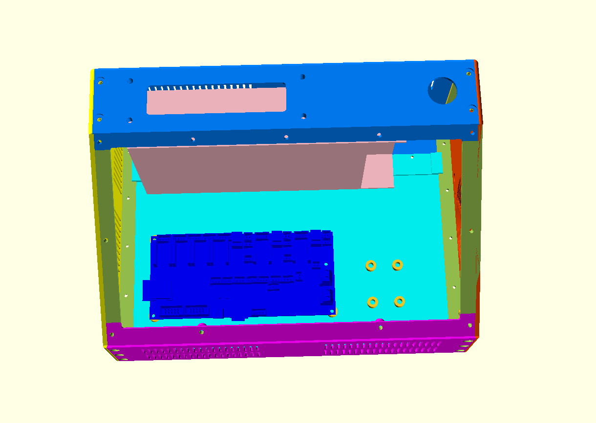
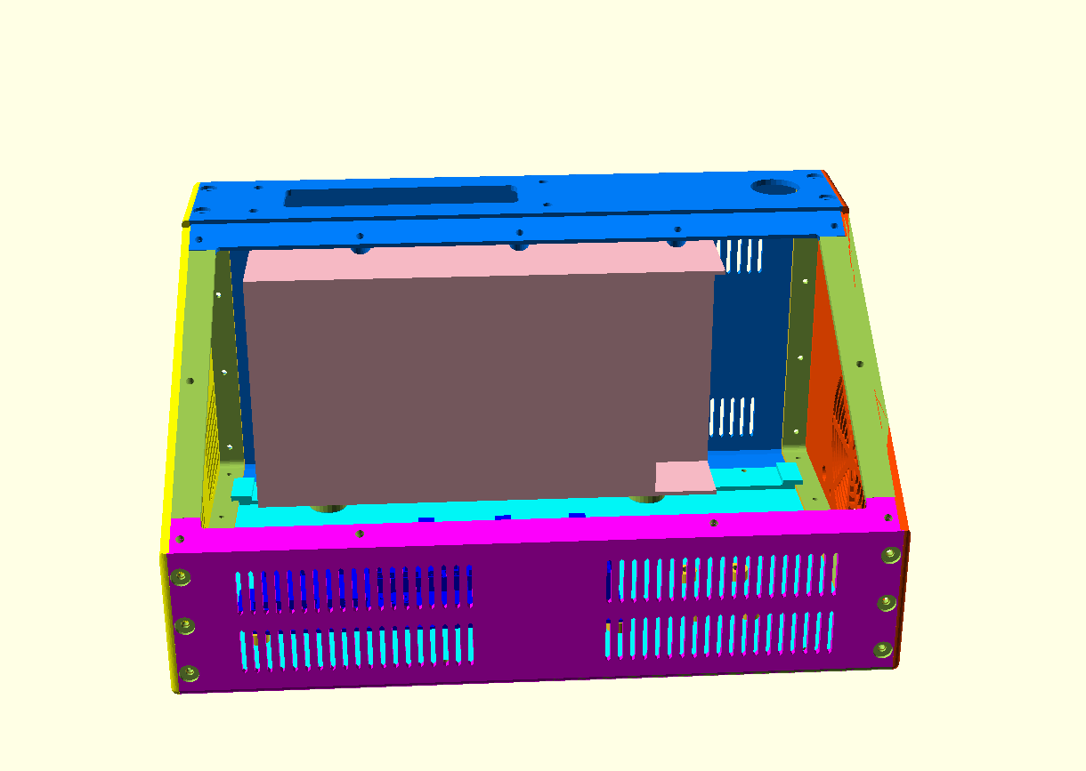
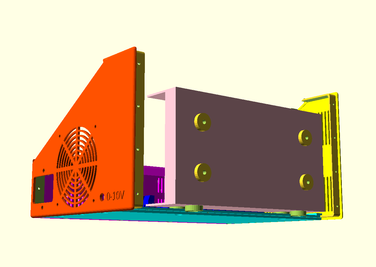
EXAMPLES WITH MOCKUP_PSU and CDYV3 board:

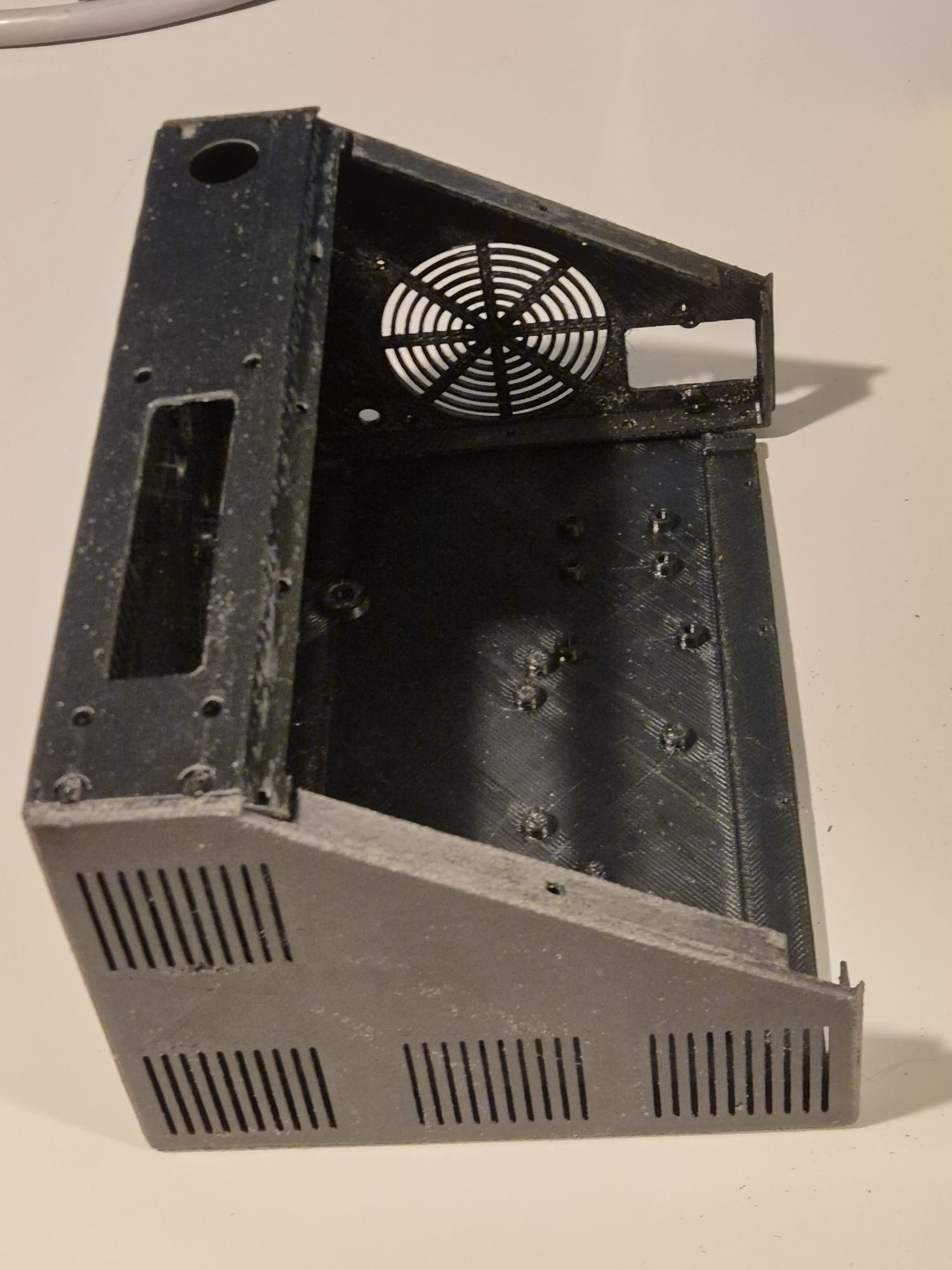
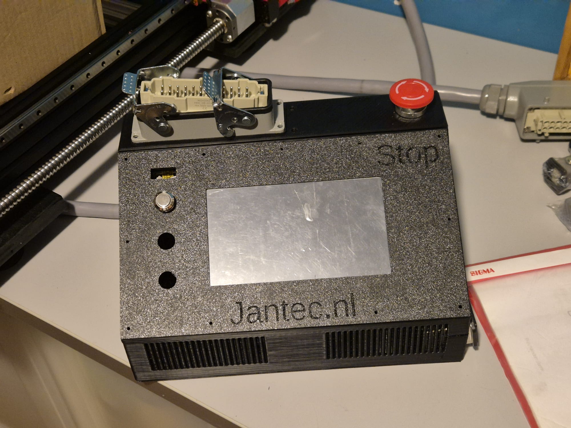
EXAMPLE OF A previous release PRINTED IN 1 PIECE:

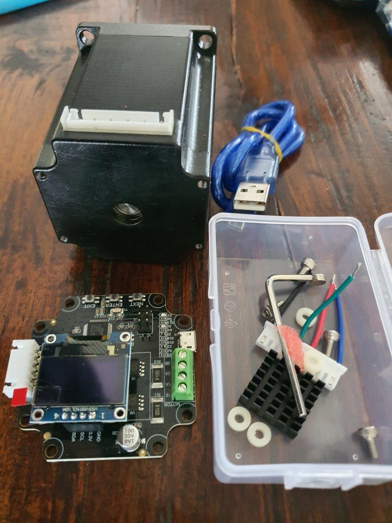
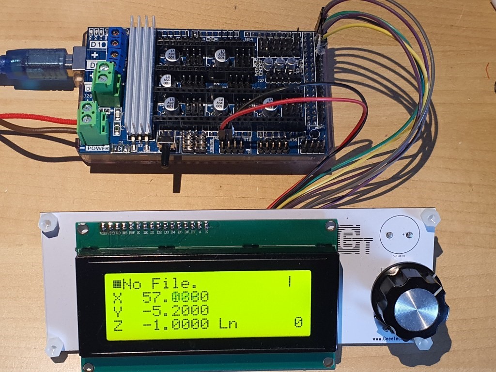
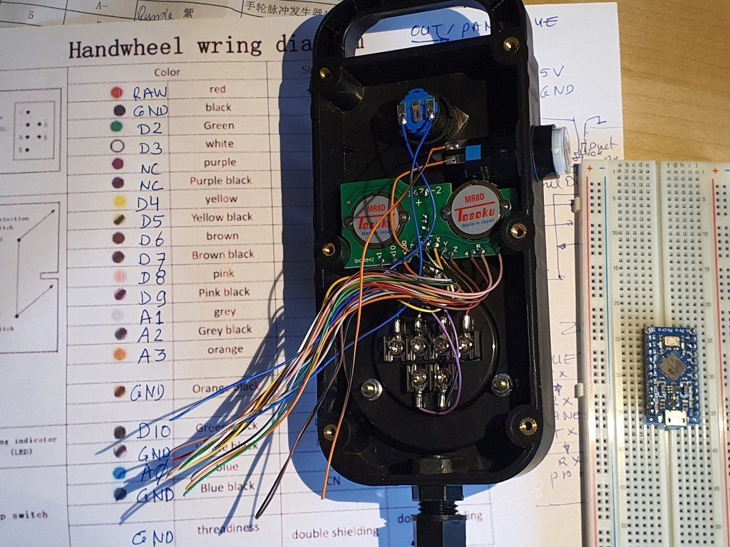
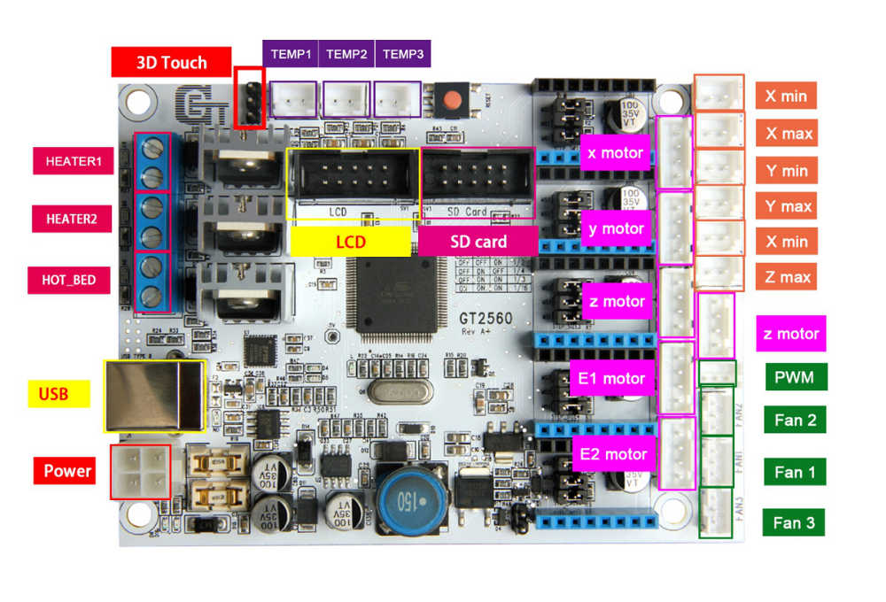 The main reason to NOT use this is the fact that the GT2560 board just has not got enough pins available onboard for things like a handwheel and other outputs for accessories. The second thing that prevents me from going this way is the fact that it proved impossible to have a functional LCD attached that shows things like position, speed, status et cetera.
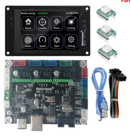 Also for this setup: No option for squaring the dual Y axis setup. But- this is a very neat solution for smaller machines. or larger, if you use external drivers. The nice option of this setup is the 3.5 inch LCD that also comes preconfigured for CNC. I use this for my small 3018 CNC.
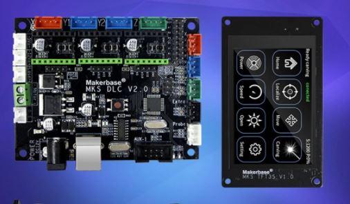

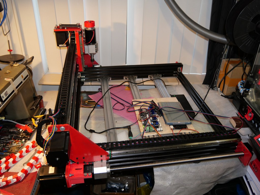


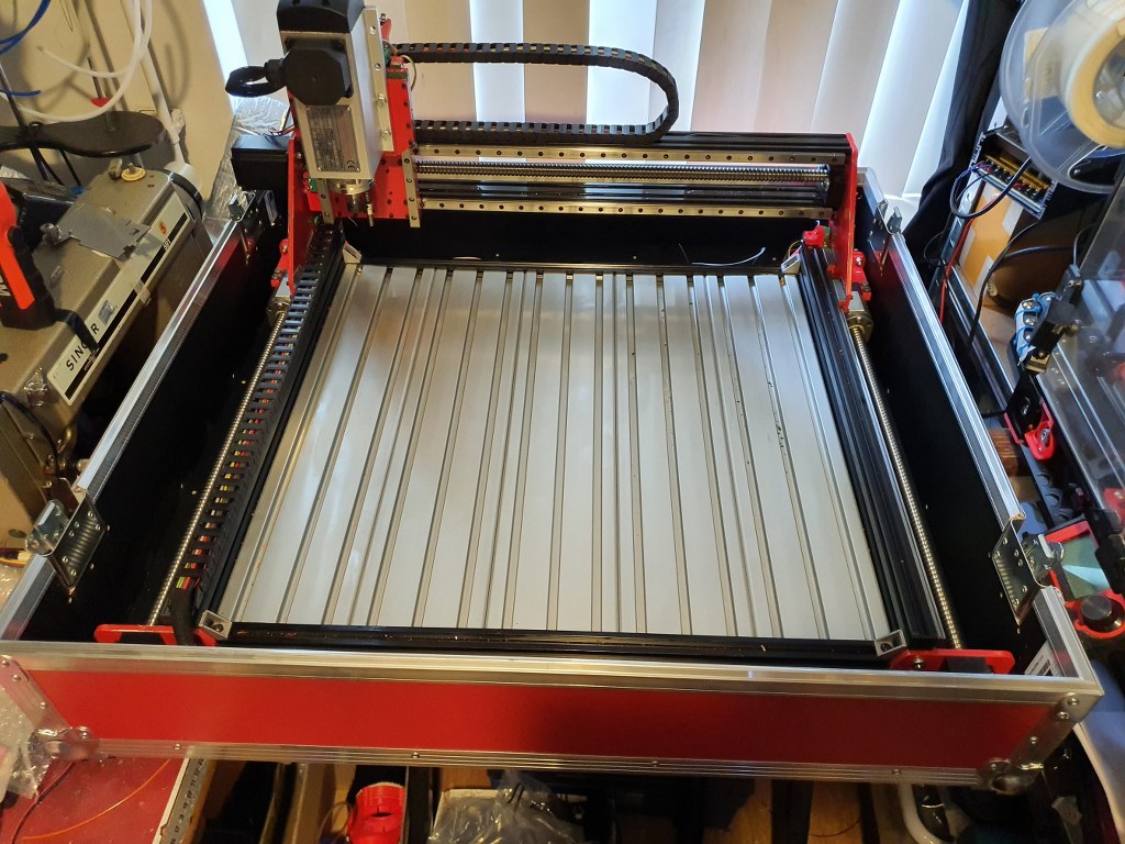
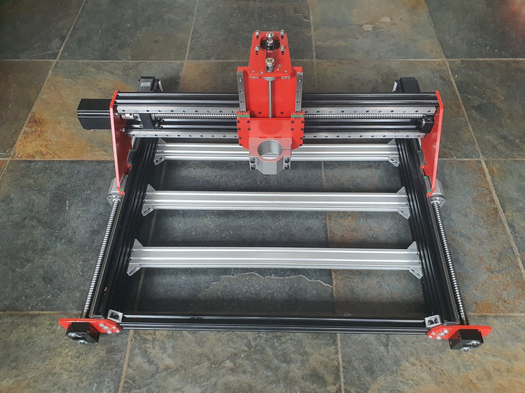
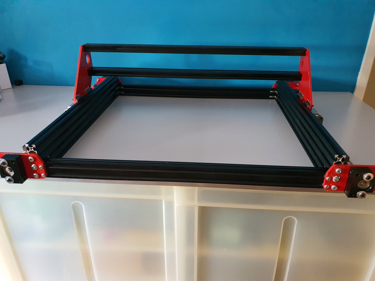
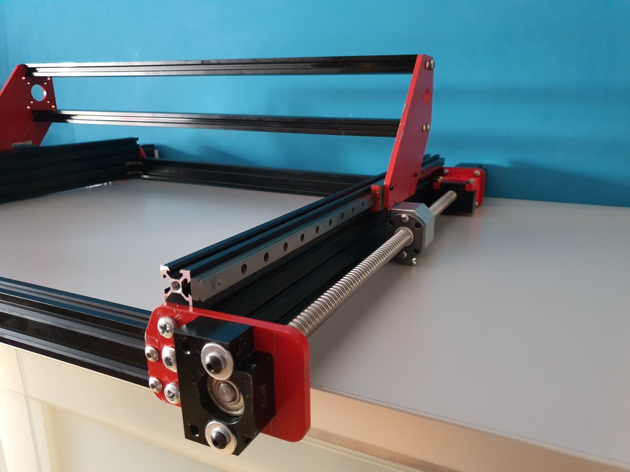
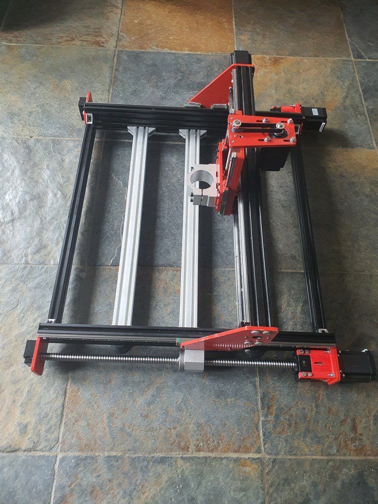

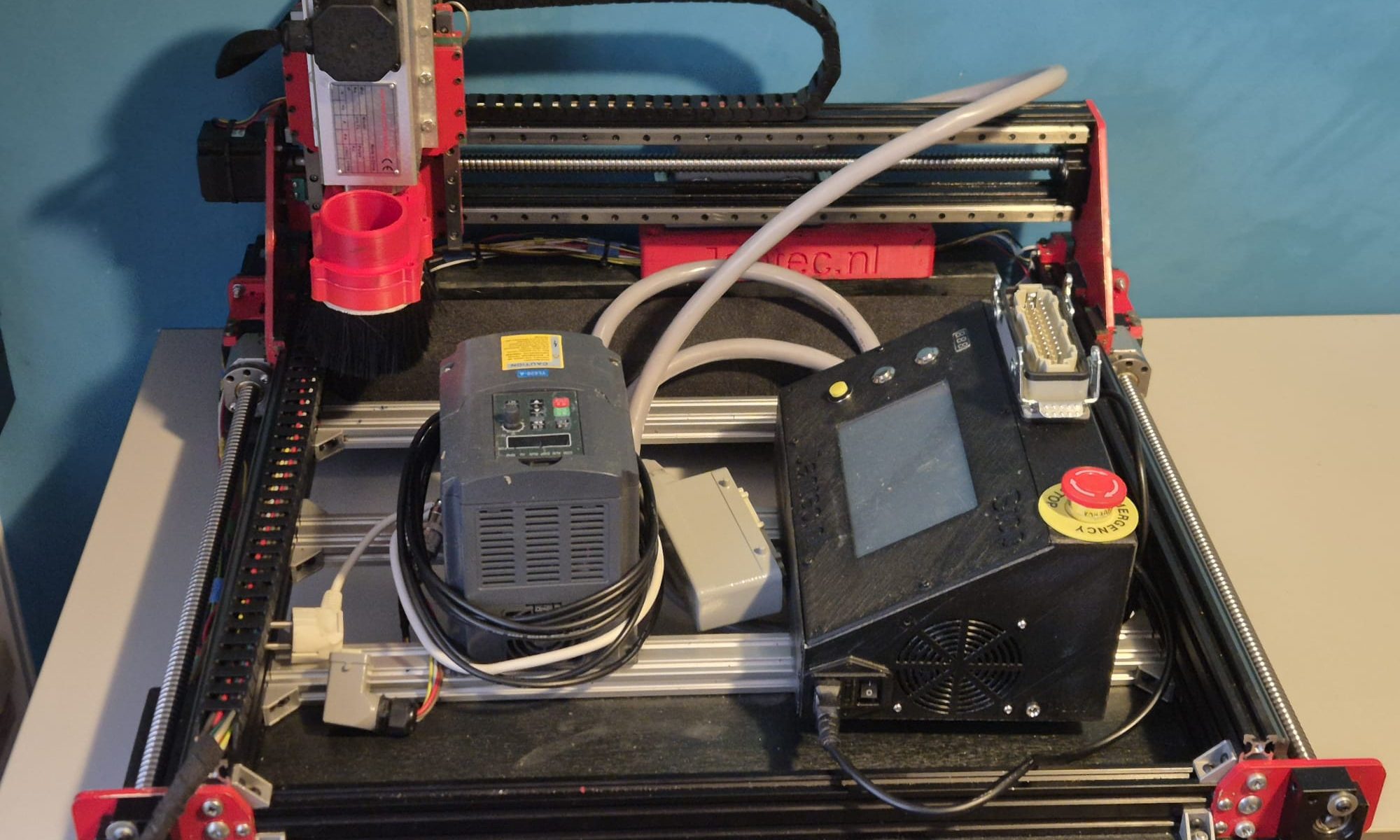
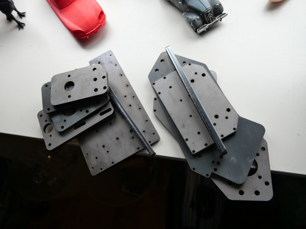
 and a simple GRBL 3- axis board that works very well. But- it would be nice to make a CNC machine that can really work with aluminium and possibly also with copper and brass. I have already done some research in the past about what sort of CNC machine would be right for my goals. And the IndyMill CNC macine was already on my mind for over half a year. So-last week I ordered the manual and the steel plates