

2021-05-22
Under construction-still trying to find out how to do this.
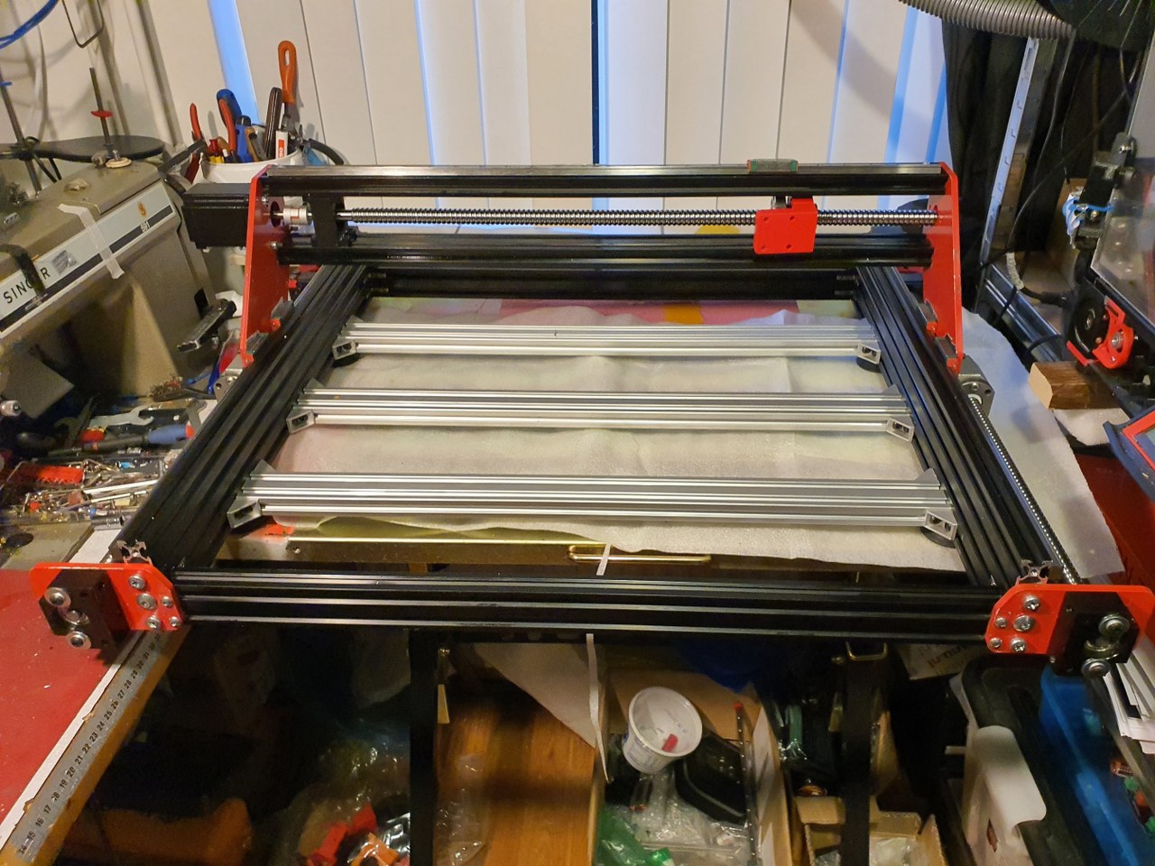
I intend to use the same method as with the Y-axes so drop the 3d printed parts as much as possible and re-use the available bearing blocks and nut holder.
For the red nut holder I only need to make a flat extension plate to connect the nut holder to the Z-plate.
For the end bearing block BF12 to the right, this is no problem. I can mount it easily on the sideplate’s outside.
The push/pull bearing block BK12 is more difficult to re-use, I will try and find a small enough connection block that is 3d printable to shape the BK12 in, and still fits in between the 2 horizontal aluminium profiles that shape the X-axis. It will be very tight so I might have to make something myself, possibly I will just mount the BK12 on a in-between piece of 2040 and first I can mill a hole in the center of the 2040 piece so the end of the 1605 ball bearing screw can gain access to the BK12… Or something like this, will try and report how it goes later!
2021-5-24: Found a possible solution with an adaption of the same Nema23 to BK12 housing as is used for the Y axis. I am printing this fast with PLA on the Ender pro, will cut off some flesh of the NEMA23 top and bottom flange and will then fit this between the 2 lengths of 2040 extrusions and see how it works! The screw holes will have to be saved, but 4cm in the center will be removed, some 4 mm wide om both top and bottom.
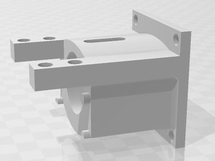
Today I made the last solution fit the X axis and got all related components to fit the X-axis. During this I found that the left bottom ball bearing slider cannot move along the BK12 block.. So, I machined some material from this block’s side bottom. That doesn’t hurt but it does impact my planning a bit. And- during the process I destroyed a piece of the PETG BK12 holder that connects the BK12 bearing block to the stepper motor and the in-between side plate. I already directly printed a new ABS part to replace the PETG and wished I had started with ABS like I dit with the Y-axes. But- look at the bright side: Now all 3d printed parts will be ABS red: like the steel plates!
You must know that I elaborated quite a lot on how to print the Neam to BK12 couplers and fount that it is not good to print these withh the face to the Nema23 motor DOWN. Instead- I printed them flat, with the side that faces the stepper motor to any side but down or up. This gives great strength to the 2 pieces that carry the mounting holes for the BK12 bearing so they won’t break during use.
And I found that ABS in my case (both ABS red and PETG vblack are Sunlu products) works better for this build because the PEG breaks under strain and ABS flexes a little but does nor break..