

Conversion of a Traction Avant 11BN from 1955 to 4 gears by using a Citroën ID19 gearbox and re-use parts of a Traction 11 differential -plus added afterthoughts at the end of the article-

Here you can read how I discovered by trial and error what I think is the best way to provide a Traction Avant 11BN with 4 gears .
The Citroën Traction Avant has standard 3 gears of which the first gear (and reverse) is not synchronized.
In my experience, this gearbox is the biggest stumbling block for this car to come along smoothly in modern traffic.
Therefore, from 2007 to 2015 I worked intermittently on adapting an old Citroën ID/DS19 4-speed gearbox so that it works properly in my Traction Avant 11 BN.
As basis for this project, I used an ID donor gearbox from a 1964 Citroën ID19.
The ID 4-speed gearbox has full synchronization on the 4 forward gears but won’t fit into my Traction Avant as-is .
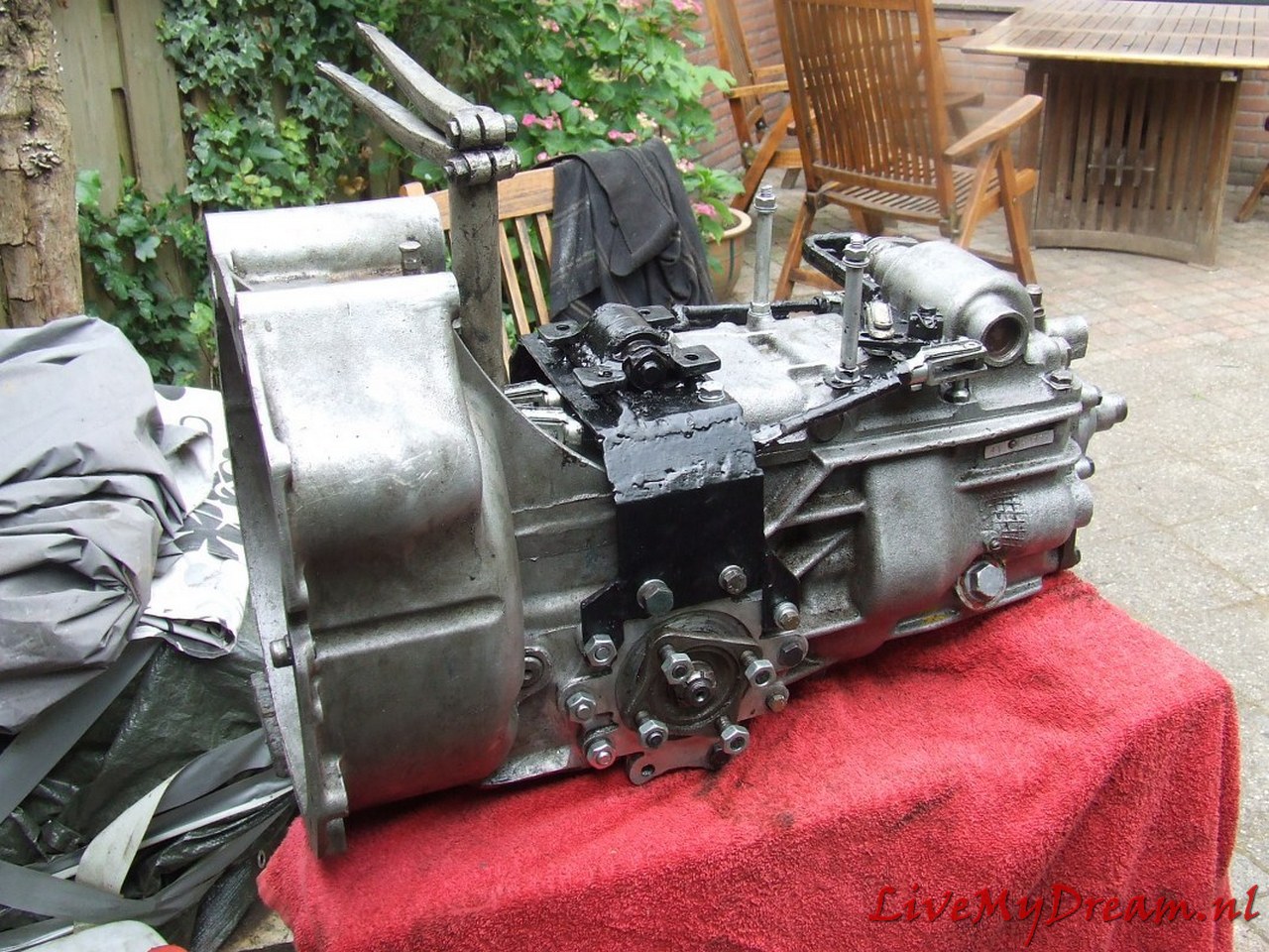
The tear-down of the ID motor, bell-house and gearbox, the modifications to the ID gearbox and the installation in my Traction Avant is available in the attached photo overview below!
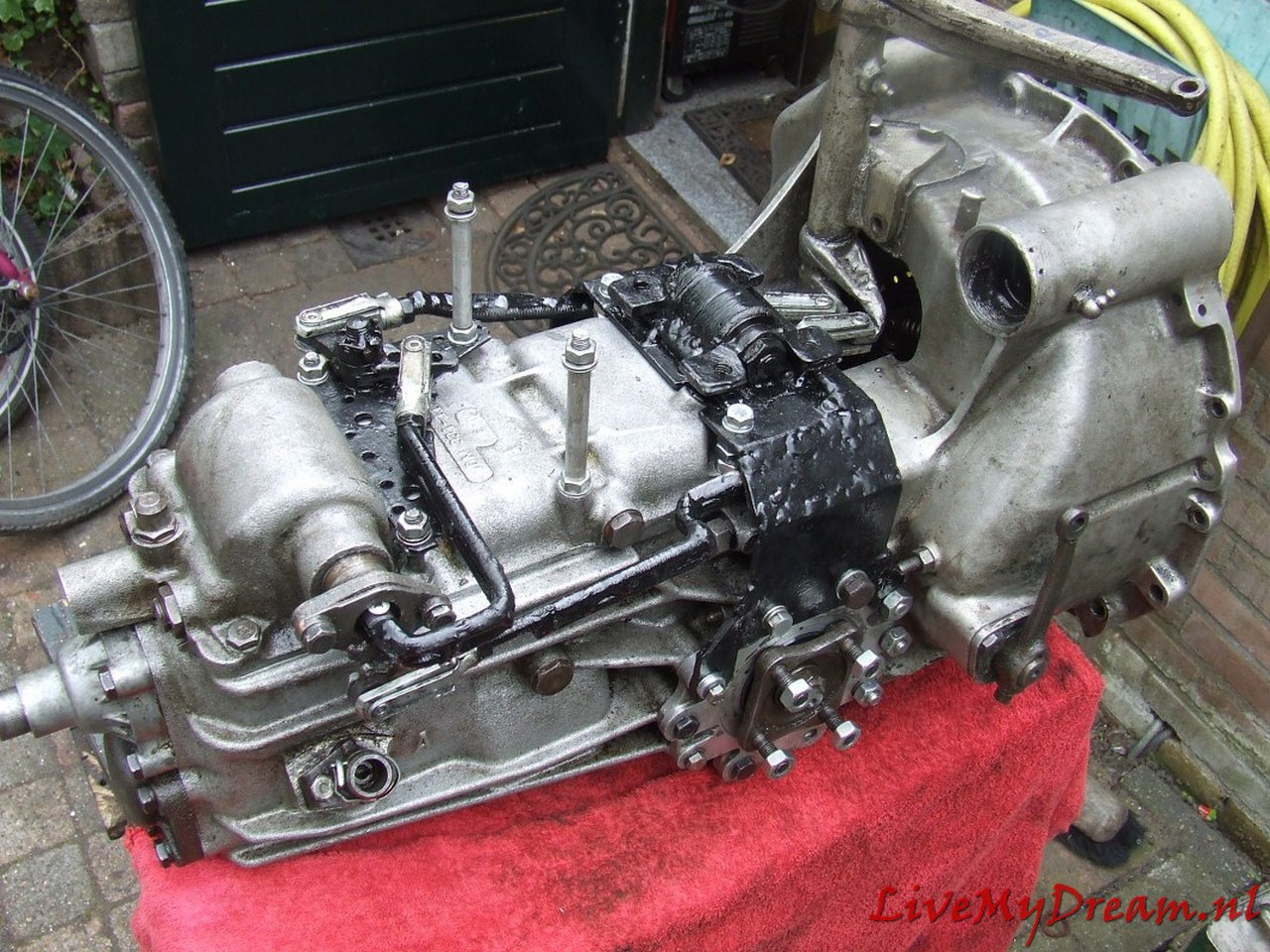
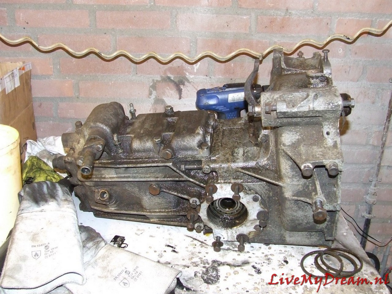
Above the rough end result is shown, before final cleaning and pre-assembly . By now (almost 2022) I have already traveled about 3000 kilometers with the 4-speed gearbox, without any problems.
All in all it has been a valuable project.
Driving the TA is perfect, shifting up and down is smooth and the car behaves very well.
An important advantage of the new gearbox is that the engine makes far fewer revolutions when driving at cruising speed.
And- due to some choices I made during the process, I also installed a 12 Volt alternator and a narrower V-belt.
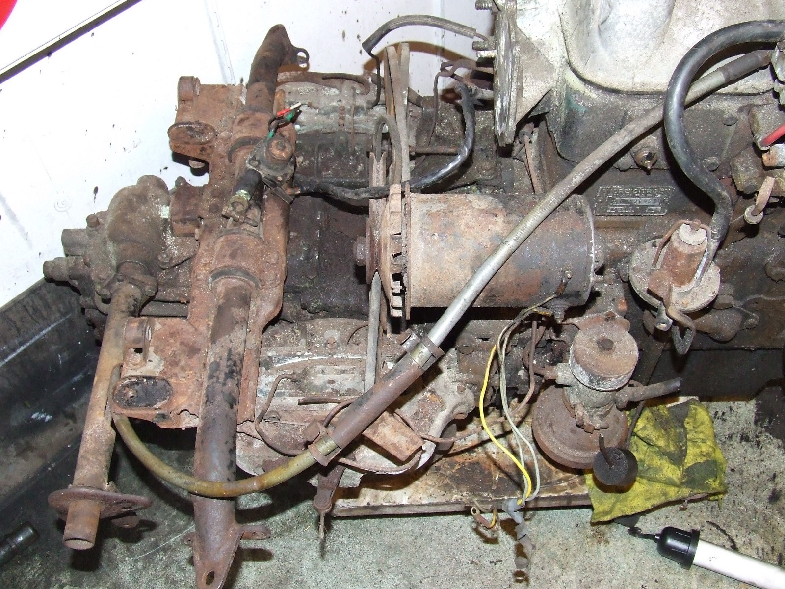
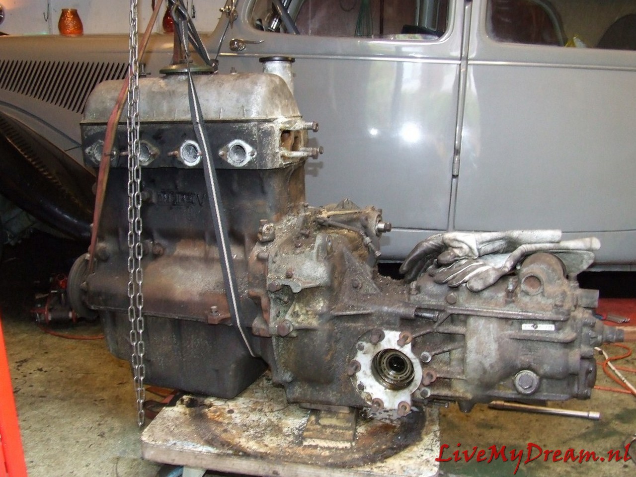
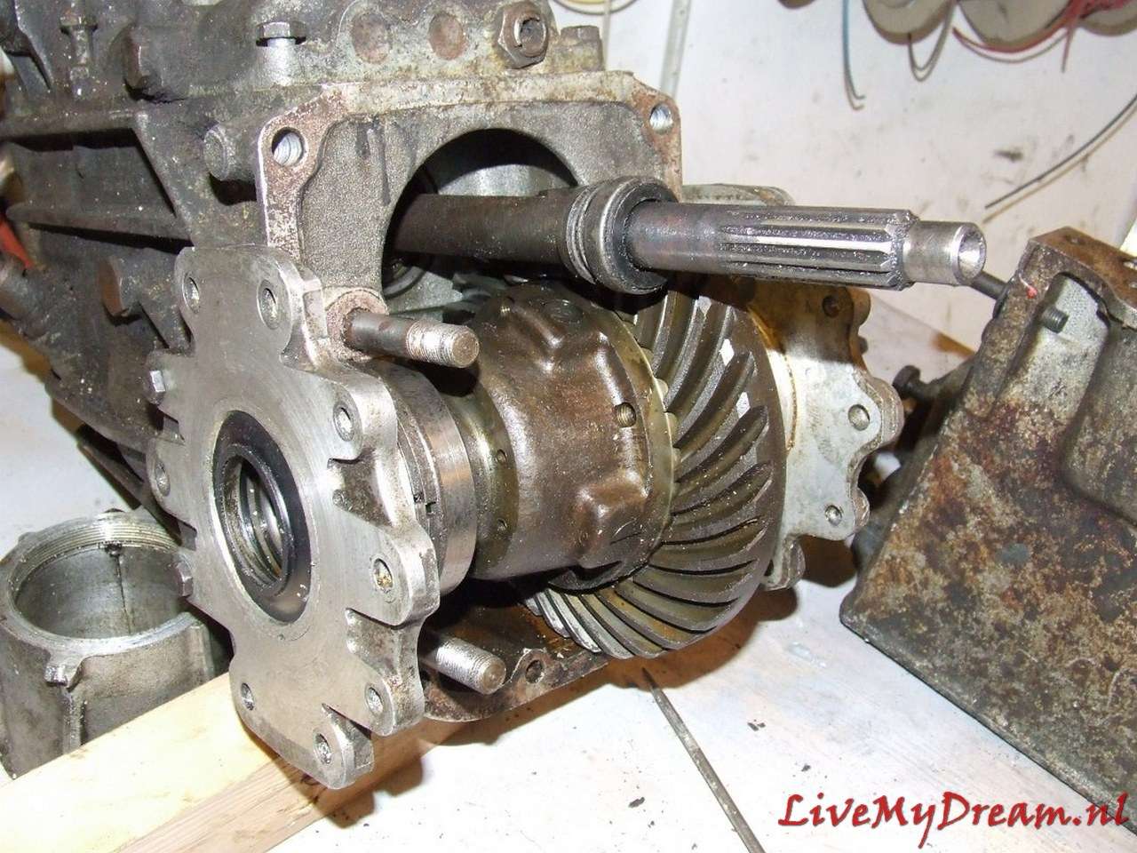
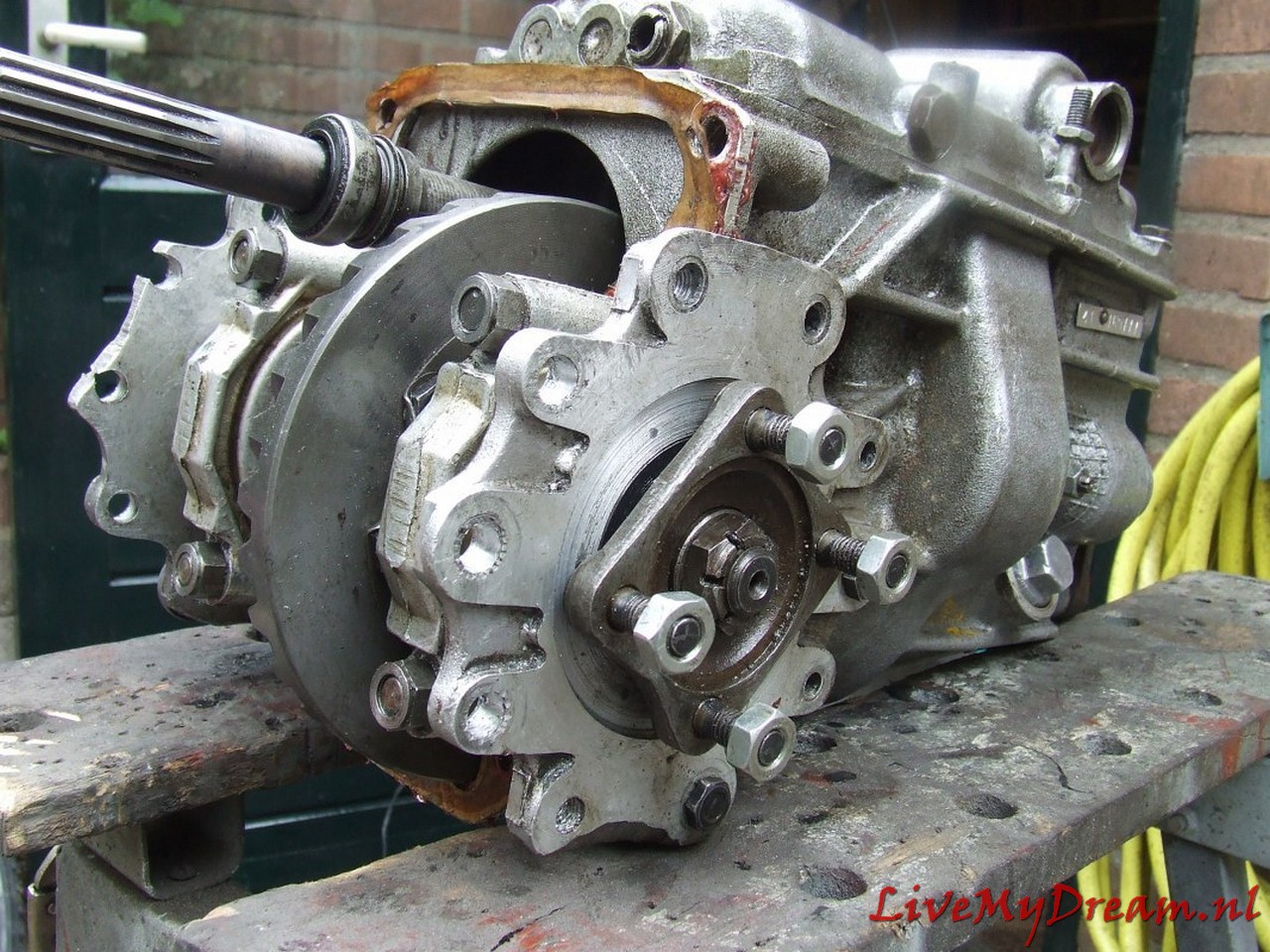
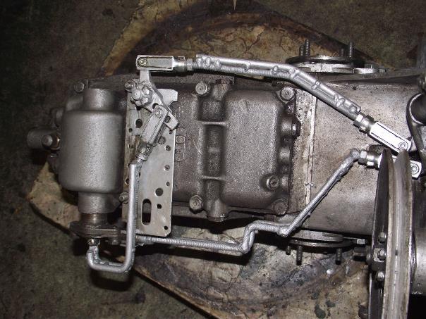
Above you see the overview of the donor long-stroke ID19 engine with the 4-speed gearbox.
At the time of purchase everything was still attached: brakes, suspension, shift sleeve, HD regulator, fuel pump, alternator and so on!
The water pump had already been removed by someone else.
The donor car had serious side damage and was declared total loss.
It was a pity but I was lucky with it.
The approach and design
The long flanges of the 4-speed gearbox have to be turned off.
From the ends of the flanges (gearbox side), filling rings are turned which will sit in the turned off flanges.
This is necessary because the bearings and seals are not available in outside sizes that will fit into the inside of the shortened flanges without fail.
New bearings and new oil seals will be enclosed in the fitting rings (or better said: adapters) in the turned-down flanges.
The shaft chucks will be turned down by about 1mm to a commercially available inner size for a bearing and seal. (35mm axle thickness)
The flanges are turned out by 3mm on the outside to allow the axle jaws to mount properly on the TA’s internal body shafts.
A stainless steel ring/bushing is turned to allow the outgoing internal TA shaft to rotate tightly in the ID crown gear.
In other conversions, this ring/bushing is usually not installed, but the lateral pressure on the end of this shaft without a fitting bushing becomes, in my opinion, too great to be able to drive it for very long without wear.
The ring/bushing has an oil groove on the rotating inner side. This ring/bushing is needed on 1 side of the donor ID crown wheel and is tightly crimped into the crown wheel.
The ID shaft rotates tightly in the ID crown wheel and is slightly thicker than the TA shaft. The difference in thickness is corrected by the stainless steel fitting ring/adapter/bushing.
The satellite wheels, internal gearbox drive axles and differential housing of the TA are reused.
The satellite wheel (which of course fits the pignon gear of the ID box) comes from the donor ID box.
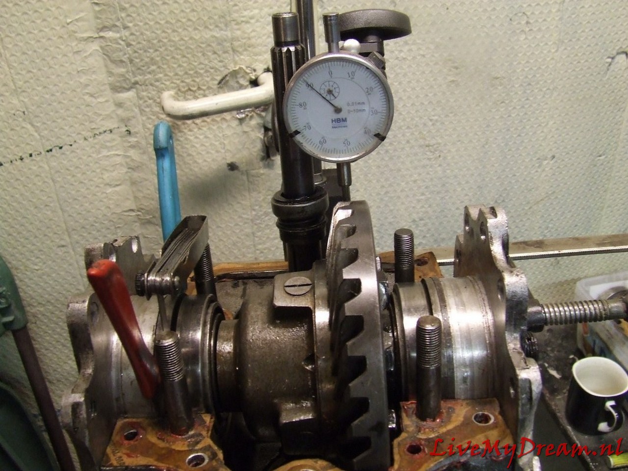
After the conversion of the satellite components you will install it and you will determine the preload on the Timken bearings again and make new spacer rings to fit the whole with the correct preload in the Differential ‘clock’ properly.
Measure the play of the crown wheel according to the workshop manual, and so on. This solution is robust and will not break or wear excessively.
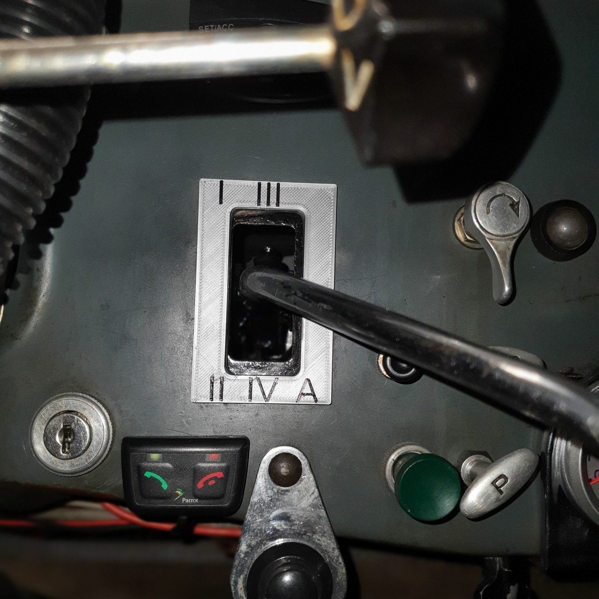
Controlling the gears was also an important issue for me, because the Traction Avant has a different standard gear change sequence and the known ‘conversions’ to 4-speed all have an extra button or lever to operate the reverse of the gearbox.
DOWNLOAD Roger Williams’s: “MORE STRIDE IN YOUR GLIDE”
I chose to convert everything so that a regular H-fork 4-speed + reverse operation is created:
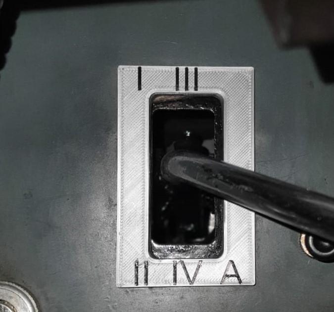 · via the TA’s original shift rods – by converting the selector/levier in the cab – by doing a conversion on the gearbox with new shift rods ‘outside out’ from the control levers at the bottom of the shift tower to the original 4-gear controls.
Axles removed and further work on turning the flanges
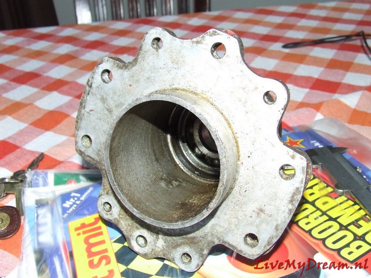
Above you see how I am turning the internal add-on rings for the flanges, in which the new bearing and the new oil seal can be mounted.
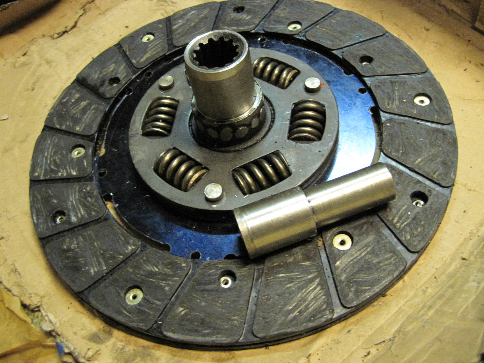
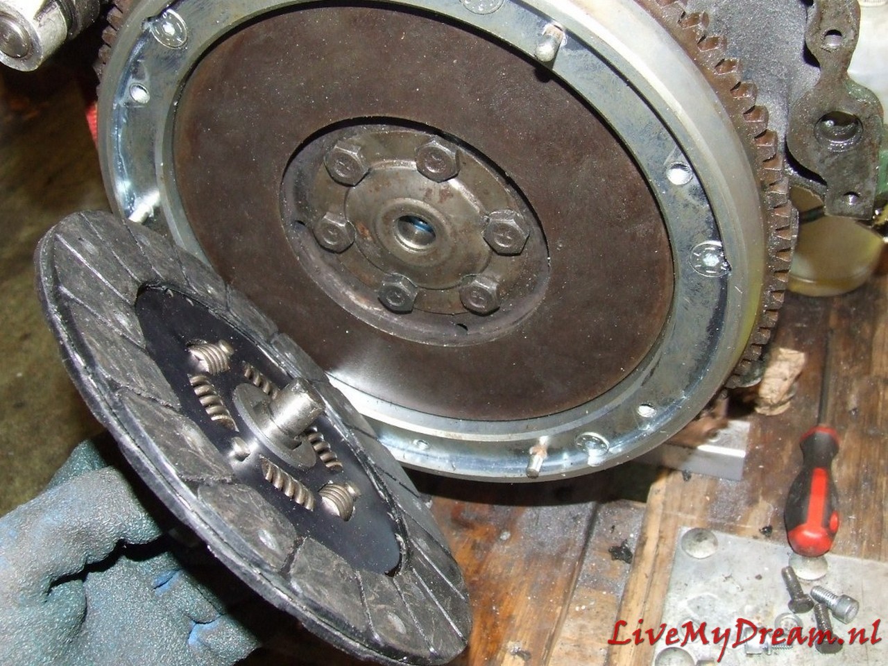
Here the center has been removed from an old ID-19 clutch plate to serve as an extension of another fitting plate.
For convenience I have used a new TA plate for this purpose, an ID plate can in principle also be used but then the keyways must be in perfect alignment so that the plate can continue to slide freely over the primary shaft.
This action is necessary because the primary shaft of the 4-gear box is shorter than the shaft of the 3-gear box and the keyway of the shaft is just not far enough into the keyway of a standard clutch plate to be able to transfer the force to the plate without damage.
On the picture above you may not be able to see it very well, but the fitting rings are locked to the flanges with stainless steel screws/rivets so they can’t move or rotate.
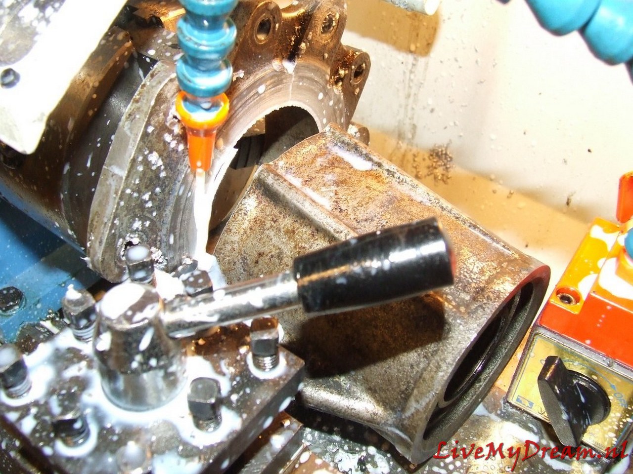
Then the flange is turned off at the outside to make room for the convex protruding parts of the 10mm threaded ends of the axle clamps. this also all just fits.
Above you can see that the flange was not yet turned out….
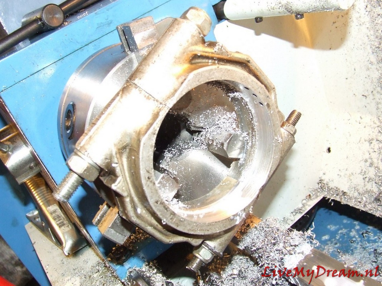
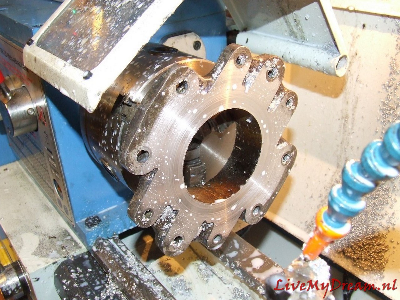
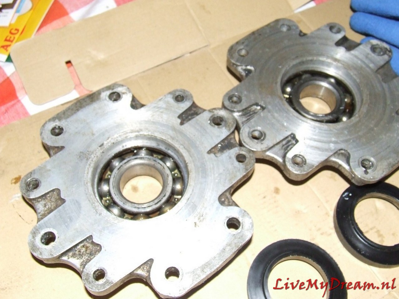
To make the bearing caps fit, they were very carefully turned out to the size of the Timken bearings in counter arrangement in the lathe. Obviously, the ID gearbox does not have a fully 180 degrees fitting part for the Timken bearin gs. This means that a plate needs to be installed between the bell house of the TA and the ID gearbox, to fill the gap.
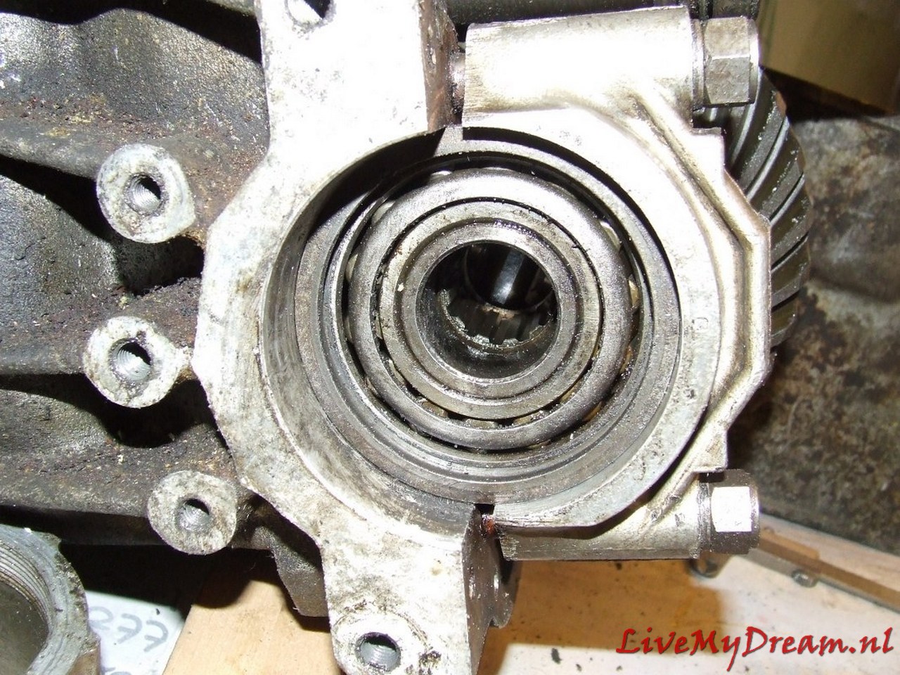
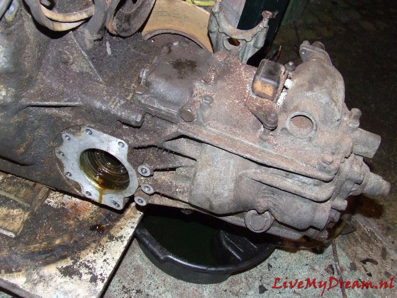
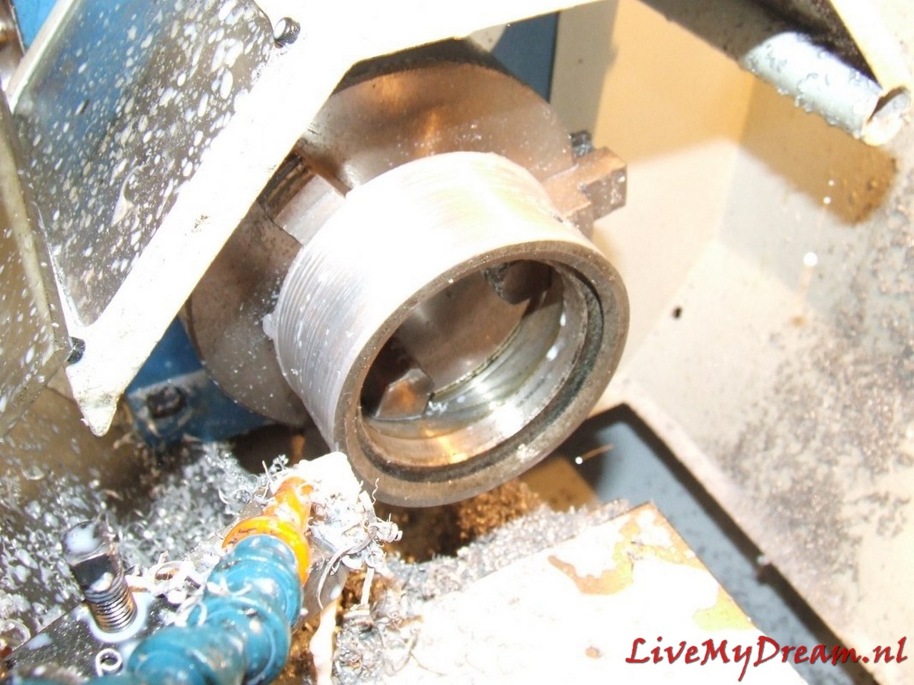
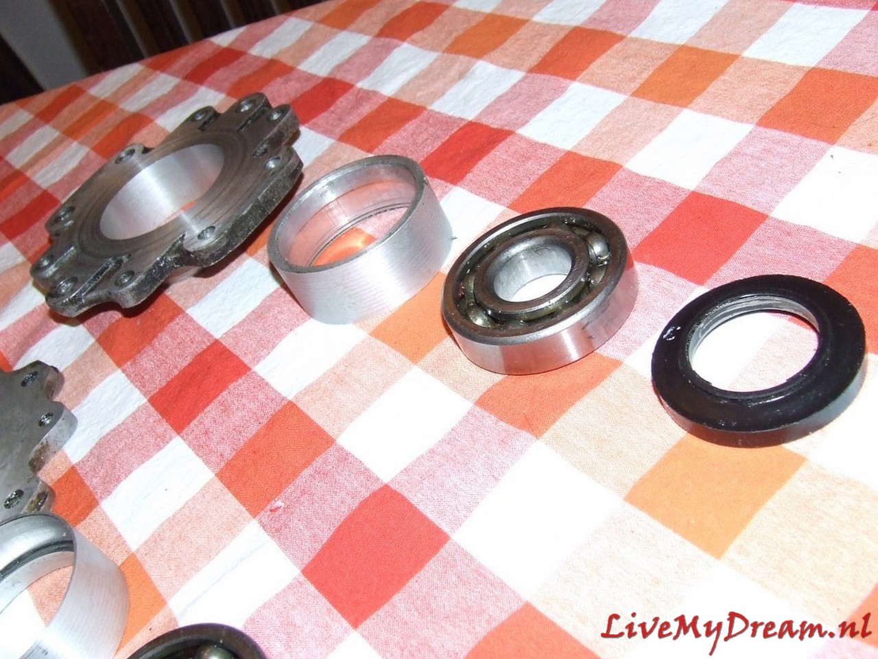
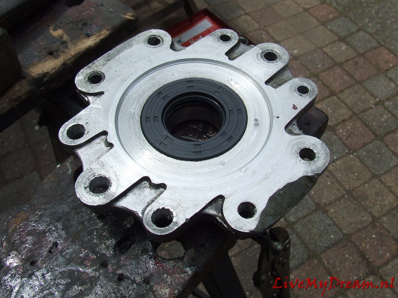
Above you see a turned-off flange with bushing, oil seal and bearing, mounted between gearbox and bell house/clutch housing
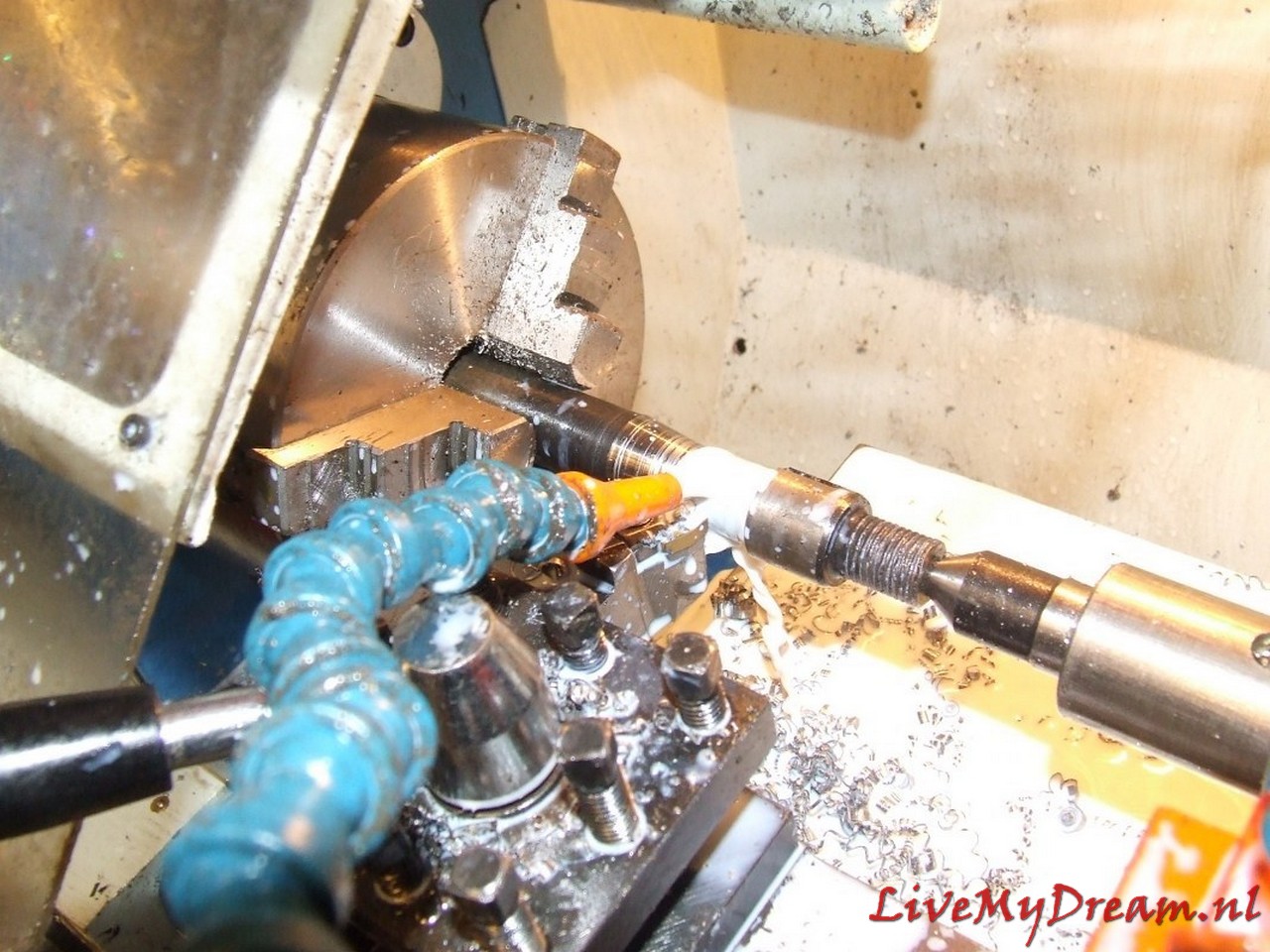
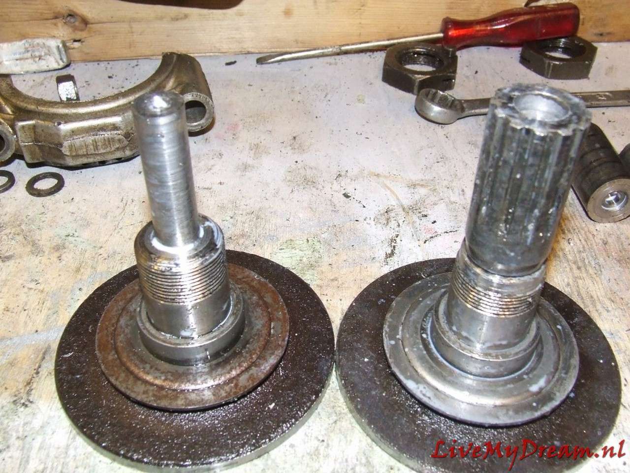
Next job: Extending the drive shaft to the accessories pulley of the ID motor.
The lengthening of this shaft was necessary because I installed a long stroke ID engine at the same time as assembling the 4-speed gearbox.
The drive of this driveshaft on the crankshaft is slightly thicker than on the Traction engine and is slightly deeper recessed in the ID engine .
See photo below where the already prepared TA shaft is on top and the ID shaft is lower.
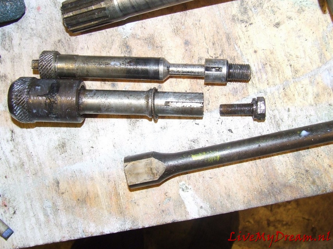
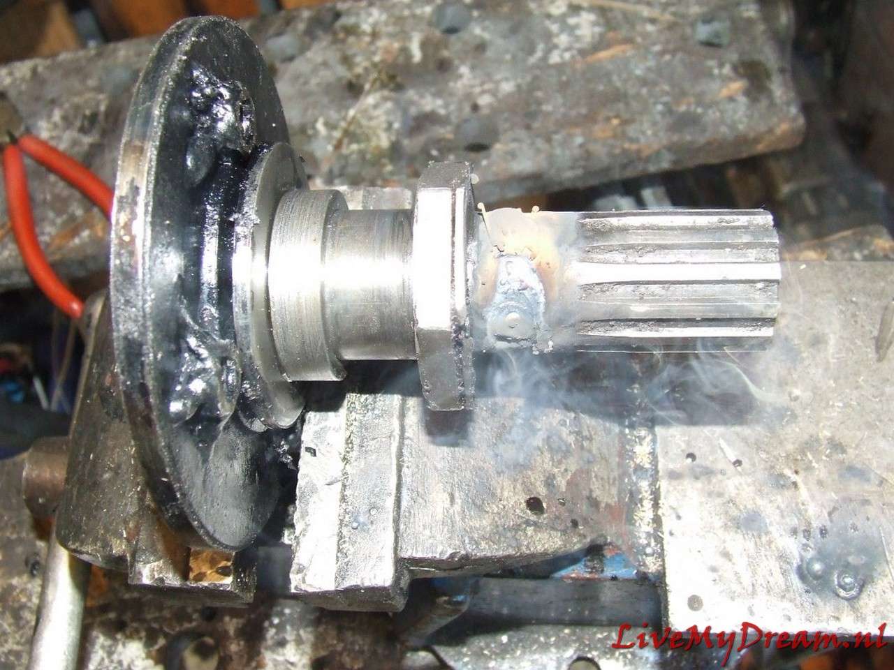
Above: Extended custom pulley shaft ready for assembly
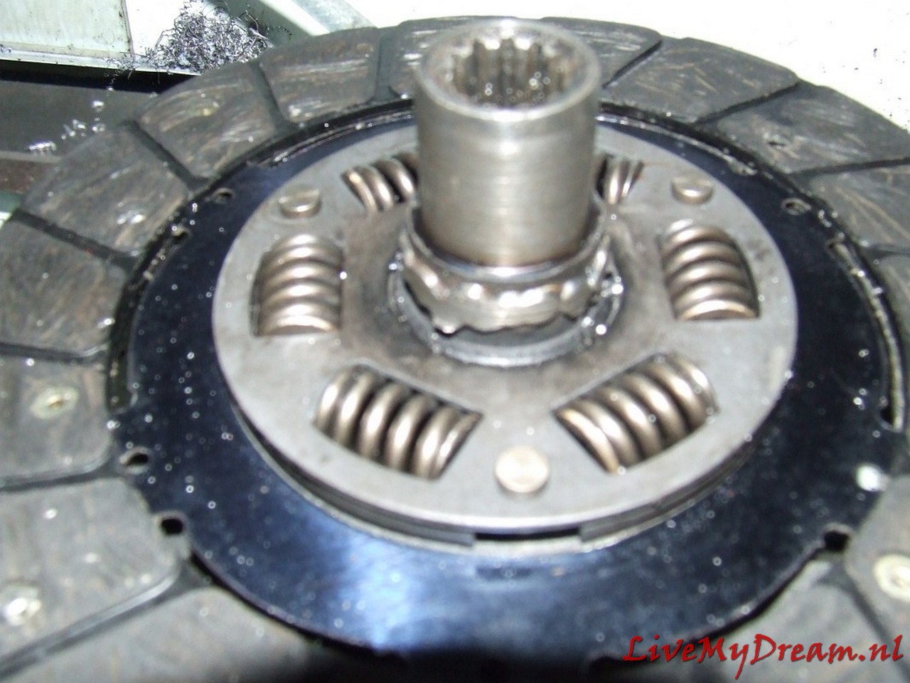
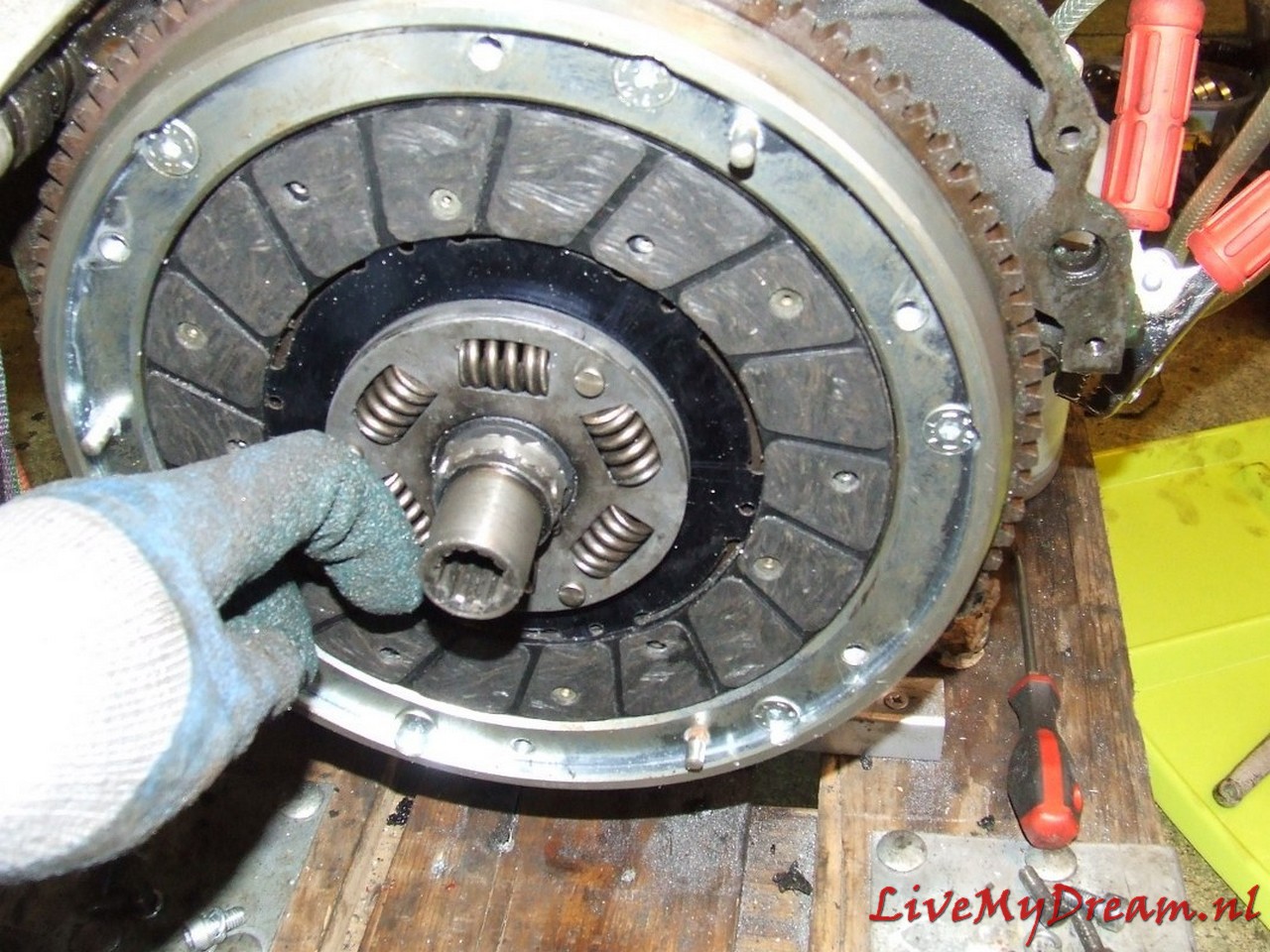
Above you can see the center of the ID clutch pin with ID keyway from a scrapped clutch plate mounted on a new TA clutch plate.
The welding was done with the specially made fitting shaft from ID to TA size tightly pressed into both keyways, this bushing is only removed after letting it cool down completely slowly.
To ensure good adhesion, the welding was first done in CO2 and later grinded out in 3 places, the fitting bushing reinserted and welded again using MIG.
After that I had the welding work checked for swings of the new keyway in relation to the clutch plate. Fortunately that was well within the norm.
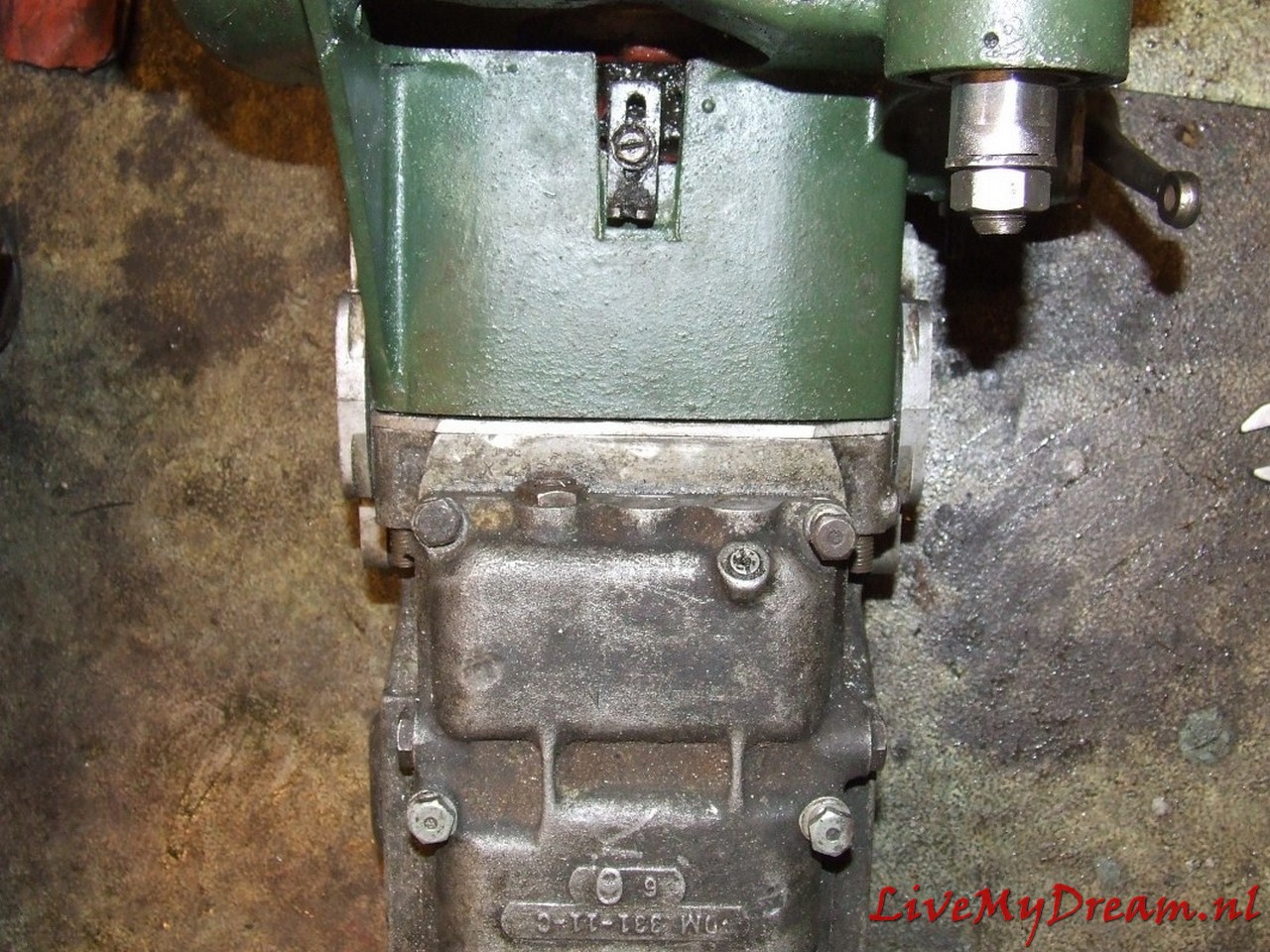
Above you can see the required fitting/shim plate of 4mm thick aluminum that I used to make the 100% fit of the TA clutch housing to the ID box.
The advantage of this solution is that the satellite housing is also free from the inside of the clutch housing and you don’t have to worry about the differential running into the clutch housing.
The reason for this required adjustment is due to the fact that the position (in the longitudinal direction) of the drive shafts on the TA compared to the ID has just shifted by 4mm.
The semi-circular recesses where the flanges on the ID box fit in and where the original oil seals on the TA box fit in are not the same on the ID side versus the side of the clutch housing.
On the TA the shape is exactly the same on both sides.
On the ID box, the hole for the flange is 4mm shallower on the gearbox side and 4mm deeper on the ID clutch housing side.
With a fitting plate between the ID box and the TA clutch housing the non-round shape due to the lack of 4mm is compensated so that the purely round shaped flanges fit exactly in the (again) round hole.
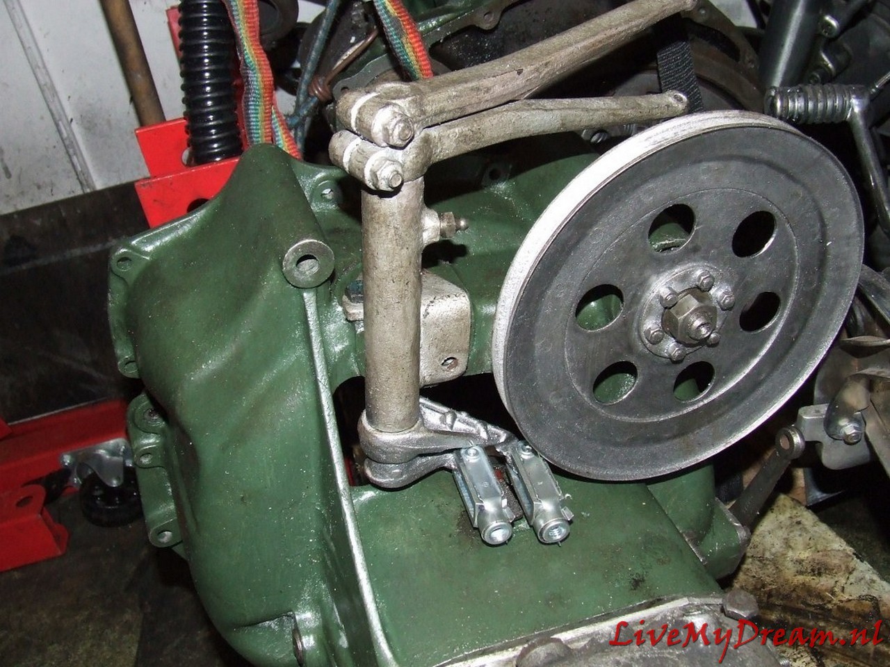
I had to completely modify the scoops of the gear controls at the bottom of the shift tower so that the newly developed rods can be operated for the ID box.
It took some thinking and trying but this solution works great!
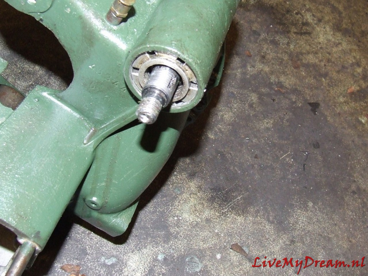
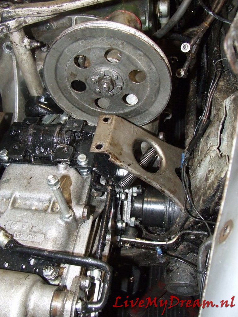
As you can see in the picture, the ID pulley only just fits next to the right-hand scoop.
By using this pulley I had to switch to a narrower V-belt, a more modern size of 9-10 mm wide.
That meant reworking the water pump pulley, and mounting a 12 Volt alternator.
Above is the 4 mm gasket plate in detail.
During the assembly process I used thin paper gaskets on both sides of the gasket plate.
That turned out to be the only way to get everything leak free.
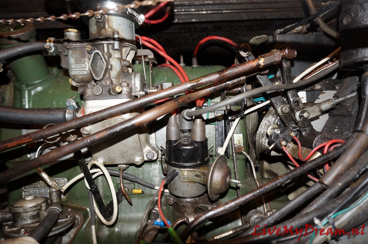
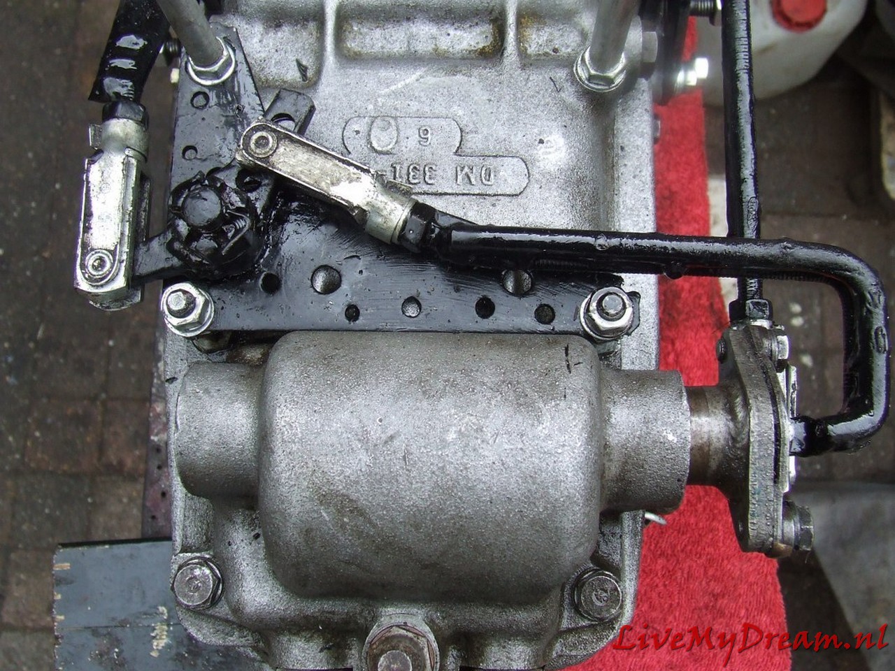
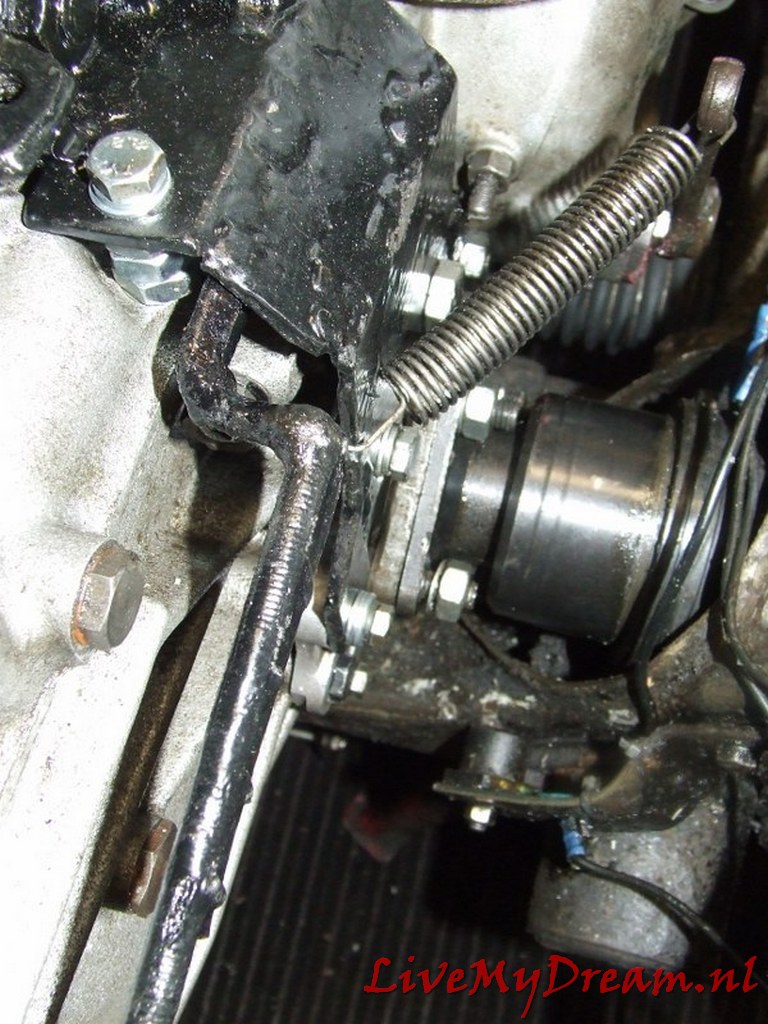
The switch rods between switch tower (left) and transmission levers (right) to the selector in detail: Small additional challenge with me was that due to the installation of the ID engine and- associated cylinder head- the carburetor suddenly ran in the path of these switch rods.
Using a water pipe bender, I was able to keep the shift rods exactly clear of any fixed engine parts and it all just fit.
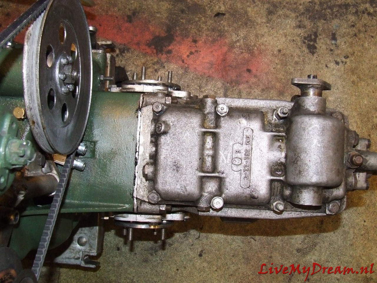
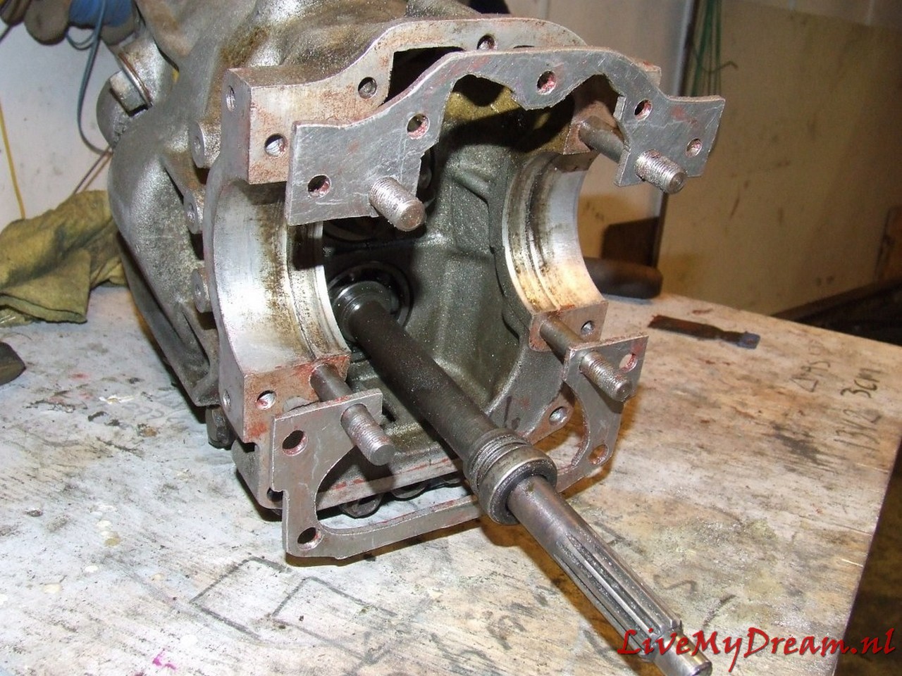
The gearbox without control rods mounted on the clutch housing. [If you look closely, you can see that here I still worked with the ID insert shafts, which I had shortened.
In the end, this solution did not work because the welded shafts kept breaking off at the weld and the included pins that ran through the inner and outer part of the shafts also just broke under high torque.
Basically, this solution is possible, but then you would have to make (or have made) new shafts].
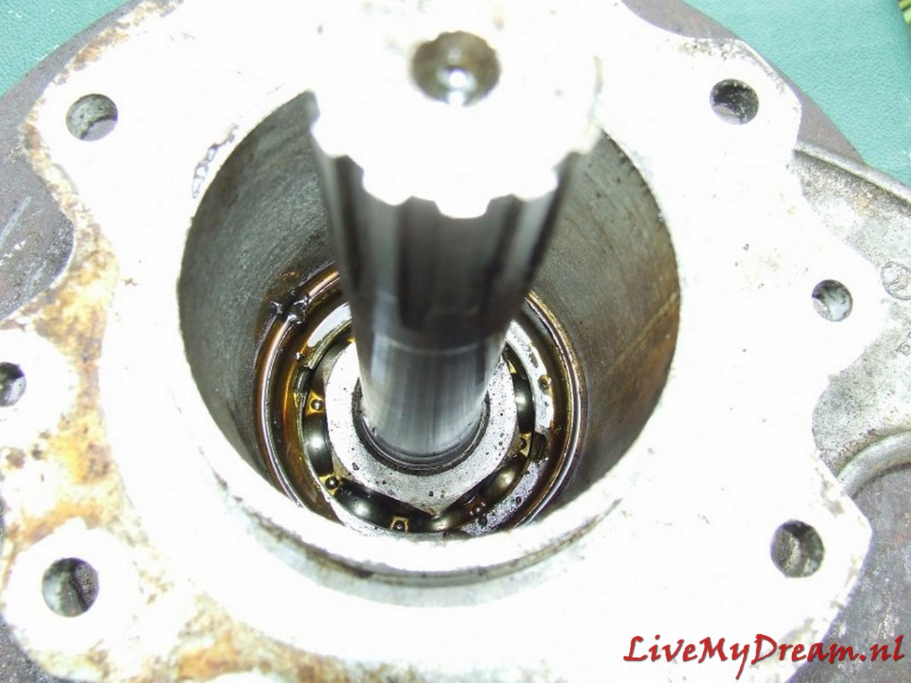
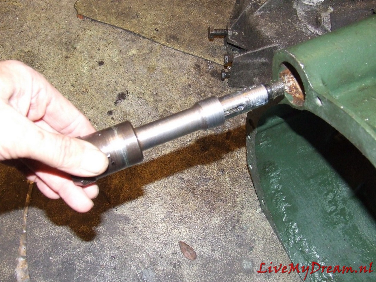
Above you can see the extension of the primary shaft by means of an extension rod that fits on the end of the primary shaft.
This part comes between the primary shaft and the top bearing of the crankshaft. The goal is to keep the primary shaft from swinging.
The extension piece in the photo was my prototype.
There are top bearings with different inner diameters in which the primary shaft fits and so again, actual experience was (again) my teacher.
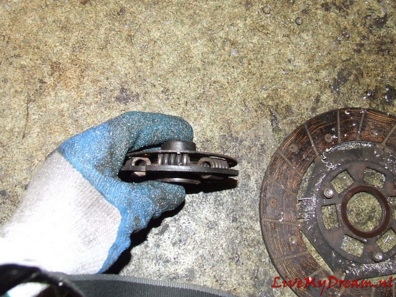
Clutch plate in the (equally mounted) attachment ring of the newly installed diaphragm pressure group
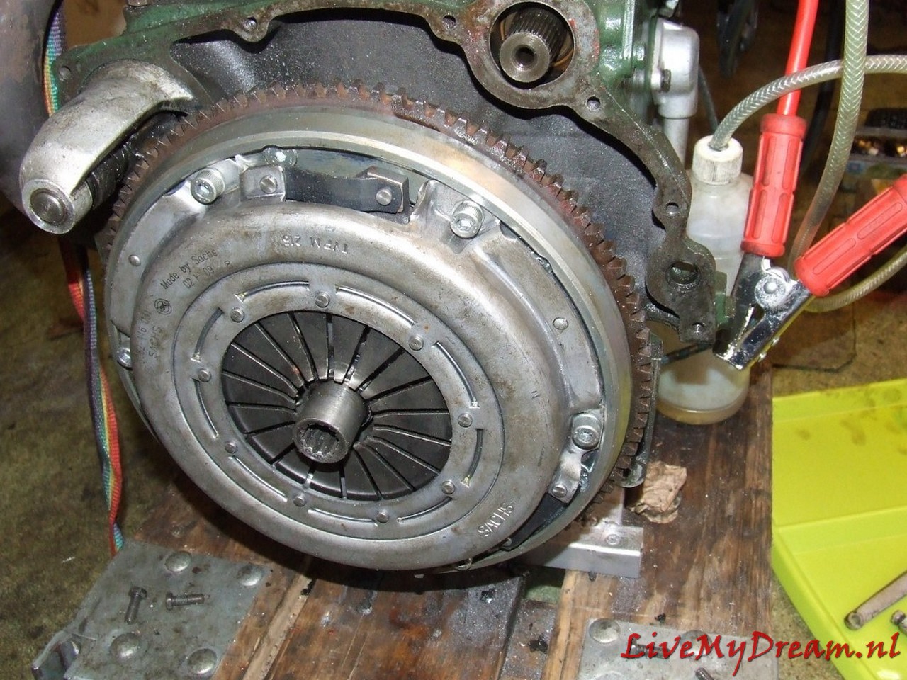
And the entire pressure plate with clutch plate mounted and the keyway of the reworked clutch plate protruding outwards
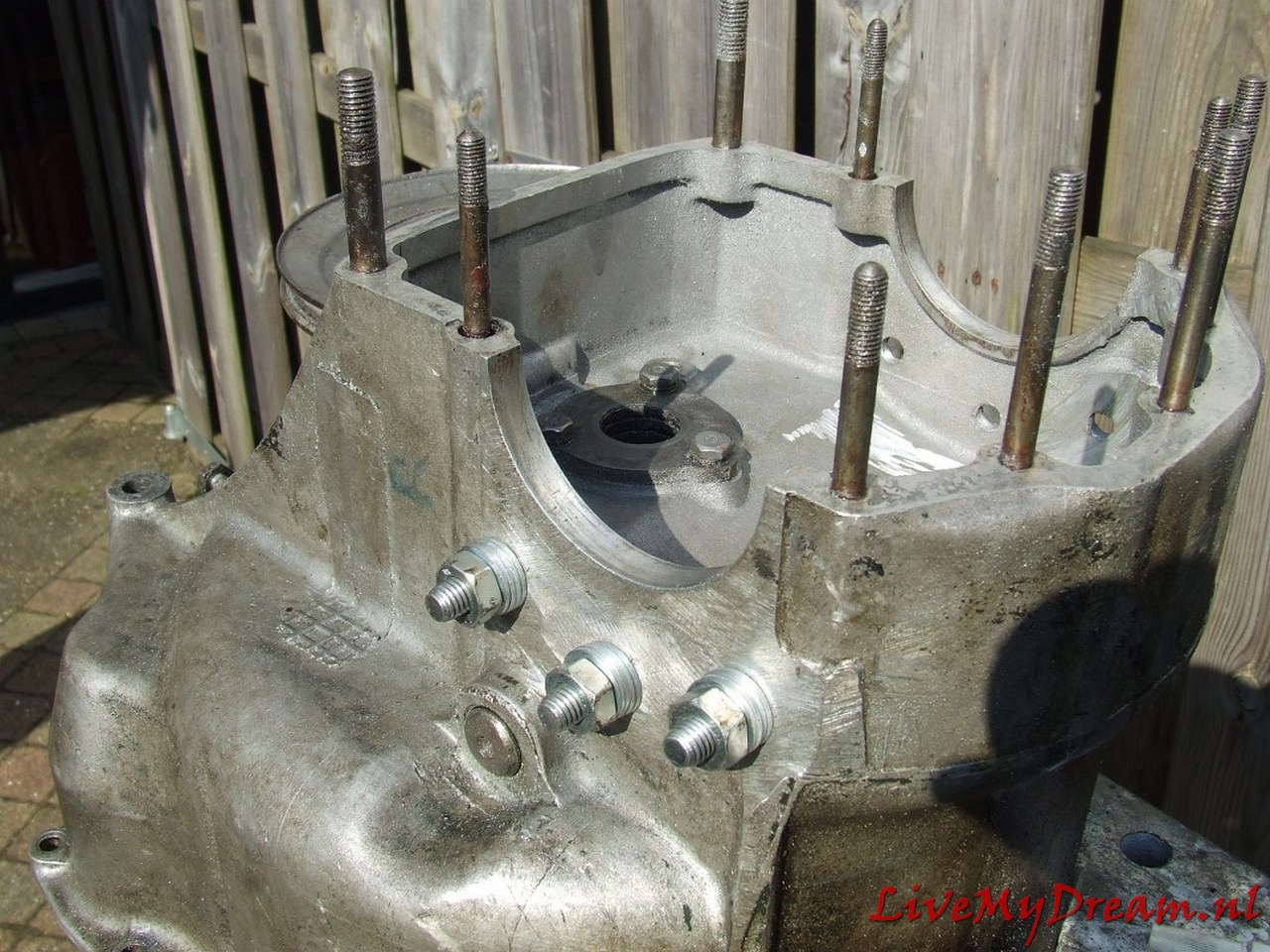
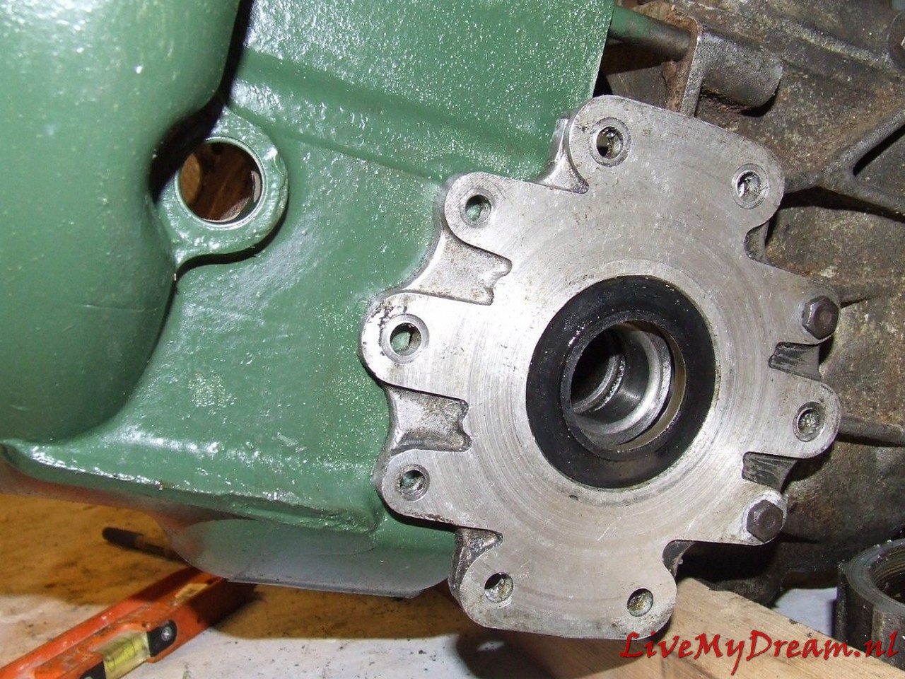
Clutch housing with M10 bolts for securing the flanges.
The M10 bolts are mounted through and through in the cheeks of the housing.
Previously I experimented with other solutions but with tapping, mounting bushings and so on I did not get it sufficiently oil-tight.
In the above solution with rings and paper gaskets it is perfectly tight!
The output axles and differential
Some builds re-use the existing ID axles and shorten these, after which they will be put together by either welding or/and putting pins through the keyed part and the remaining part.
In my experience, this does not work.
You will either have to machine new axles from scratch or do it as I describe in this article.
The reason that re-using the ID’s axles does not work is that the steel in the middle part of the axles is very flexible to handle the torque on these axles and therefore- if you weld this it will always break.
Trust me- I’ve tried multiple times with MIG, TIG, pins, and so on.
It never worked.
Or better to say: It always worked until I really came in a situation where the torque got high and it broke down at the weld, including any pins I had in the shafts.
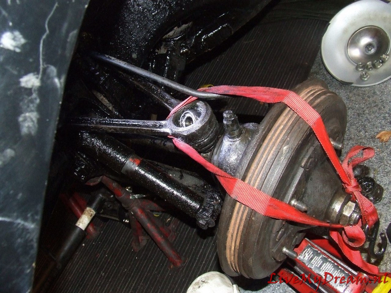
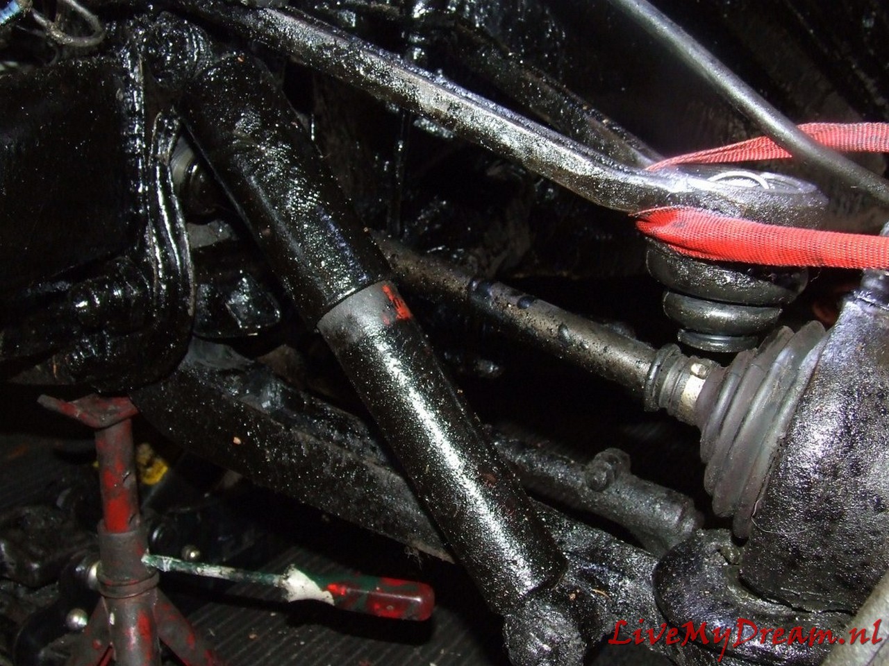
Please see the attached photo’s of failure after I de-assembled the gearbox again from the car and took the axles out, the last time:

At a certain moment (2014-4-14th) , I was fed up with this and got to do it as Roger Williams did: Make a differential that uses the TA’s output shafts on the ID gearbox.
That is what I have performed as described below:
This was a bit of a job:
Making 1 new differential from the donor parts of 2 differentials.
In itself not difficult when you think of what will fit:
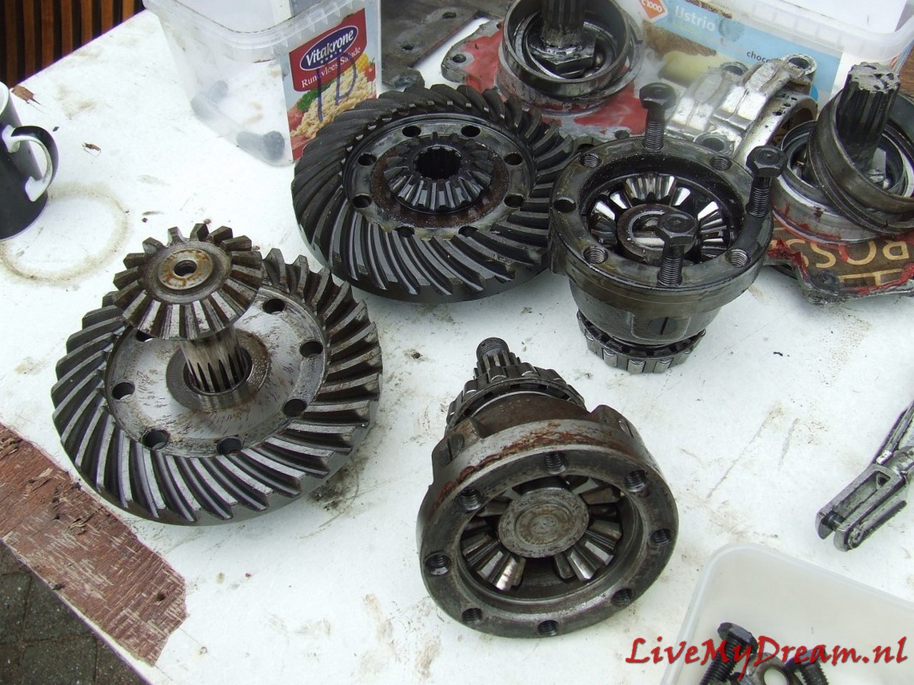
Pinion from ID is used, so the satellite gear from ID must be used.
The outgoing shafts from the TA are used so the satellite gears from the TA must be fitted.
The thinner output TA shaft is placed in the satellite gear of the ID so a fit lubricated bus/ring/bushing must be pressed into the ID satellite wheel to have the TA shaft rotate freely but tightly in it.
The Satellite housing of the TA is used (bowl-side where the gears are) with the fixed (TA) shaft attached.
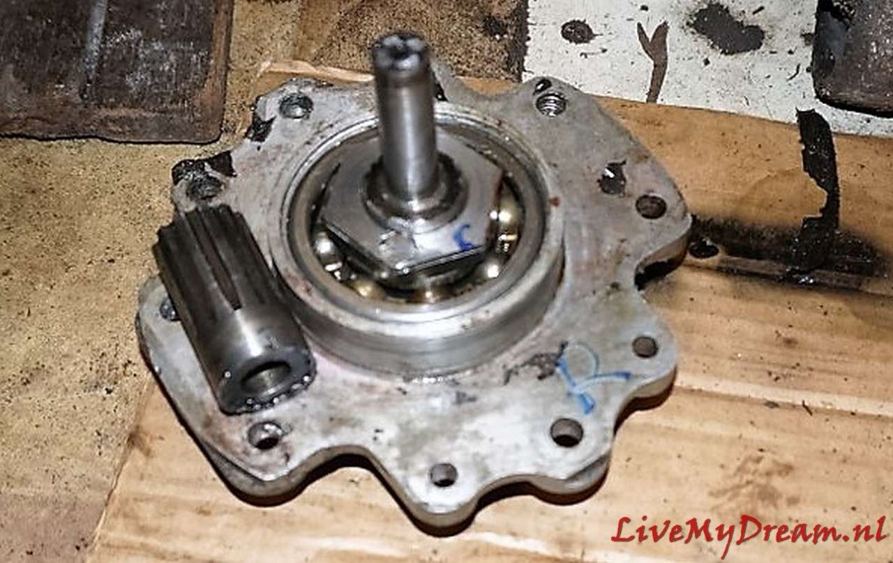
In the picture above you see the bottom left satellite gear with freely rotating output shaft.
Bottom right you see the bowl part of the satellite housing with the satellite gears and fixed output shaft.
The original TA differential works with differential outlet shafts with keyways on the outside on which the TA short output-shafts with internally keyways can be mounted.
The advantage here is that this allows you to easily replace the large retaining rings of the TA box.
So in the photo above, the bottom differential is the TA differential.
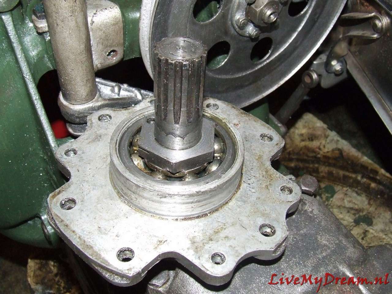
Above: Finished and assembled differential. You can see the fitting ring/bushing sitting nicely at the bottom of the top shaft, between the keyway and the differential housing.
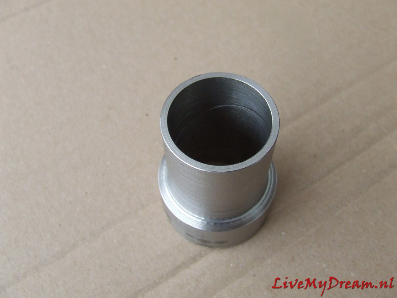
Above you can see the made fit ring/bushing with oil groove on the free turning inside.
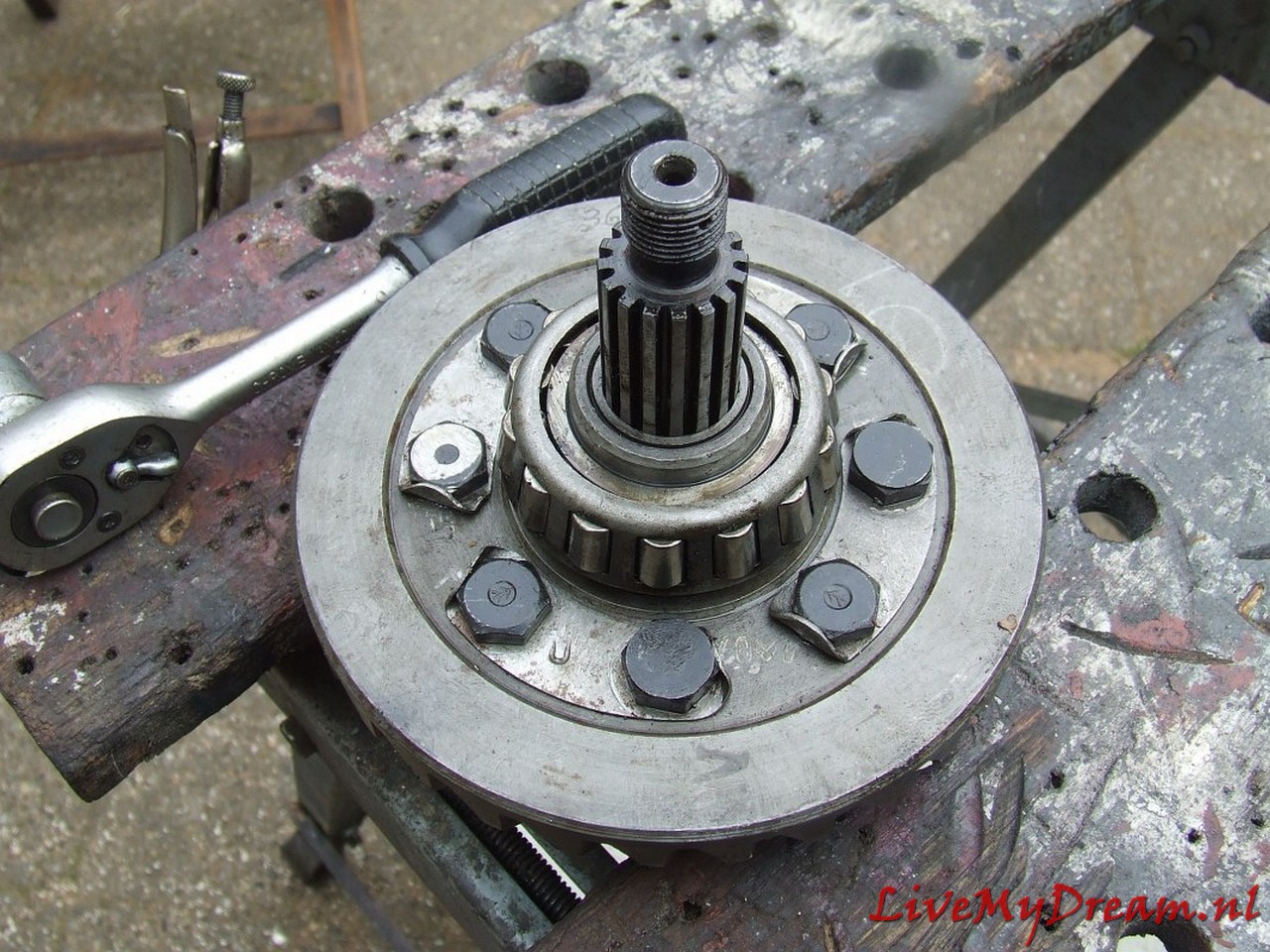
Timken bearings tighten but not too tight….
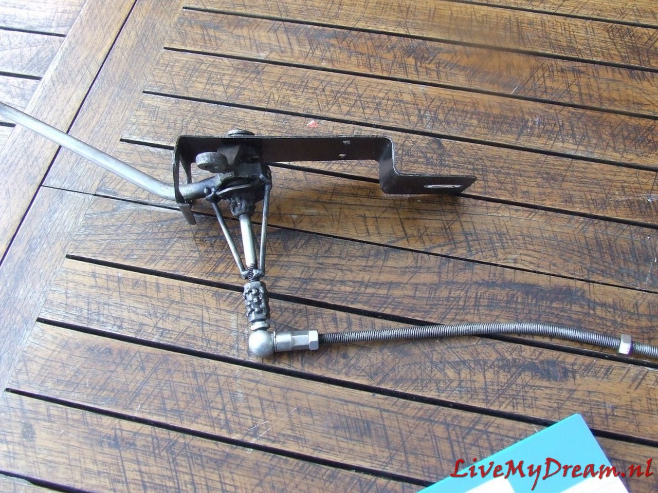
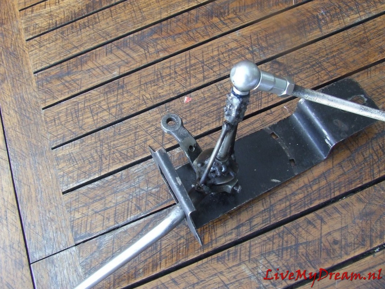
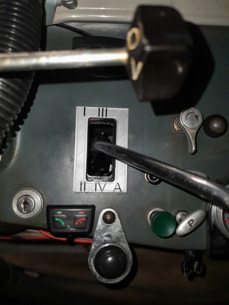
Converted switch selector/levier, in the experimental phase.
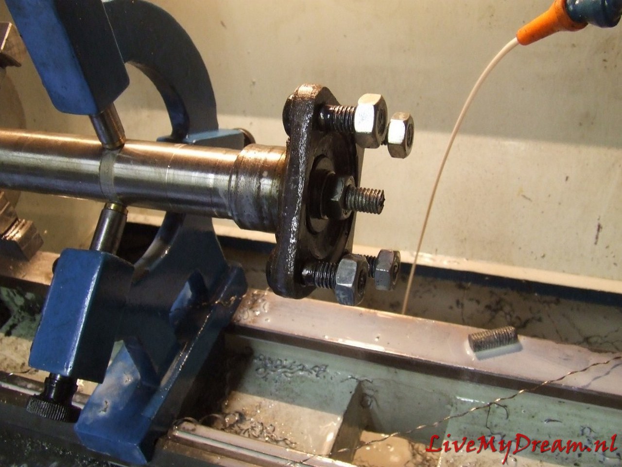
Turn shaft chuck to commercially available bearing size
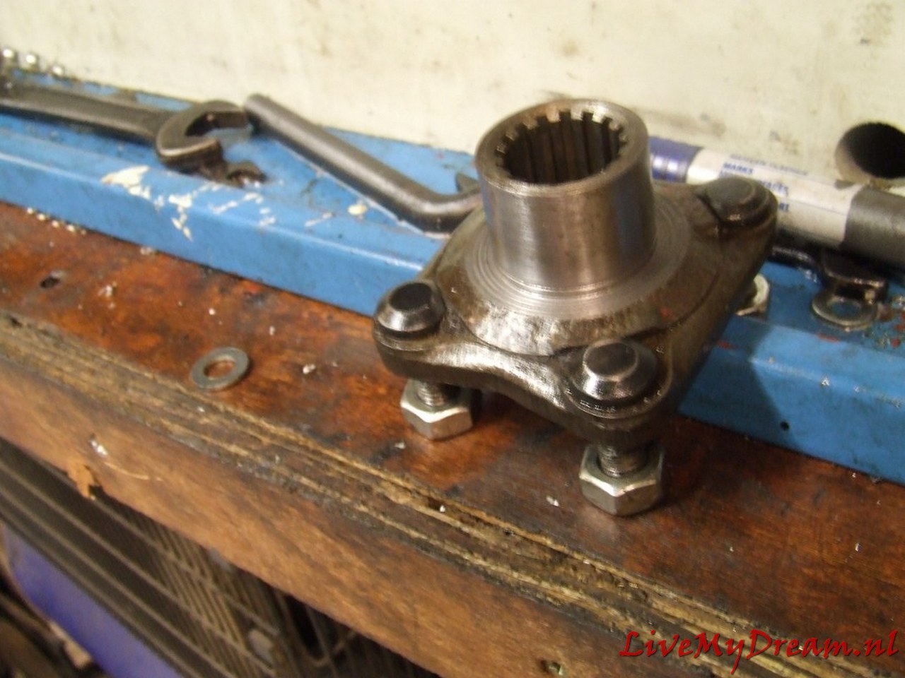
And the turned down result of the axle claw of the TA with inner groove.
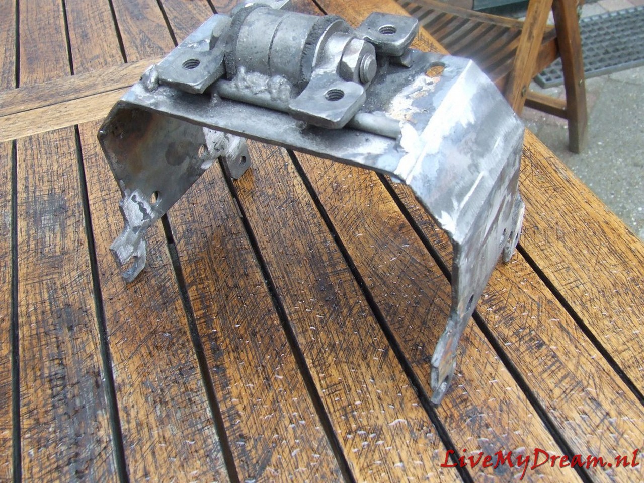
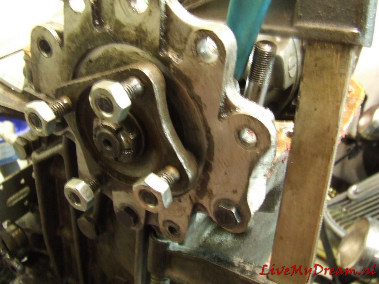
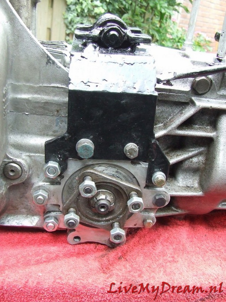
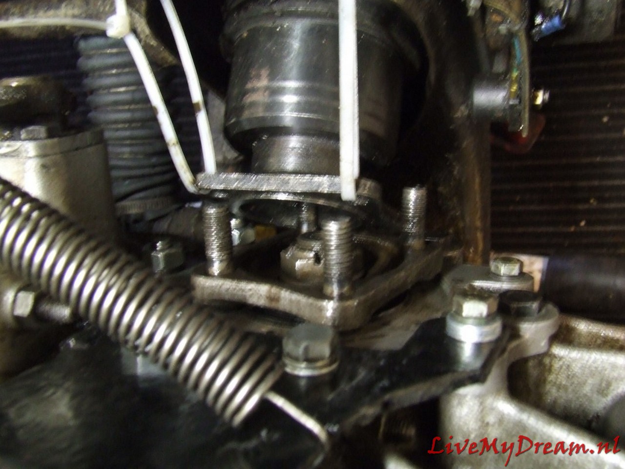
Mounting Bracket. I chose a very robust setup, since the motor/box/drive shafts are all suspended from this point. In addition, I chose to simply reassemble the cross pieces of the drive traverse to maintain sufficient strength.
Pay close attention above: On the underside of the flanges, I have ground away about 2 cm of material on both sides. This is because these points protrude from the original TA body. This means that they come up against the cradle just above the passage of the drive shafts. So I had to remove some material. I can’t remember the number of times I have assembled and disassembled the box, but at least it was so many times that I can now do it blindly and very quickly.
Above again the removed material: Handy to do BEFORE mounting!
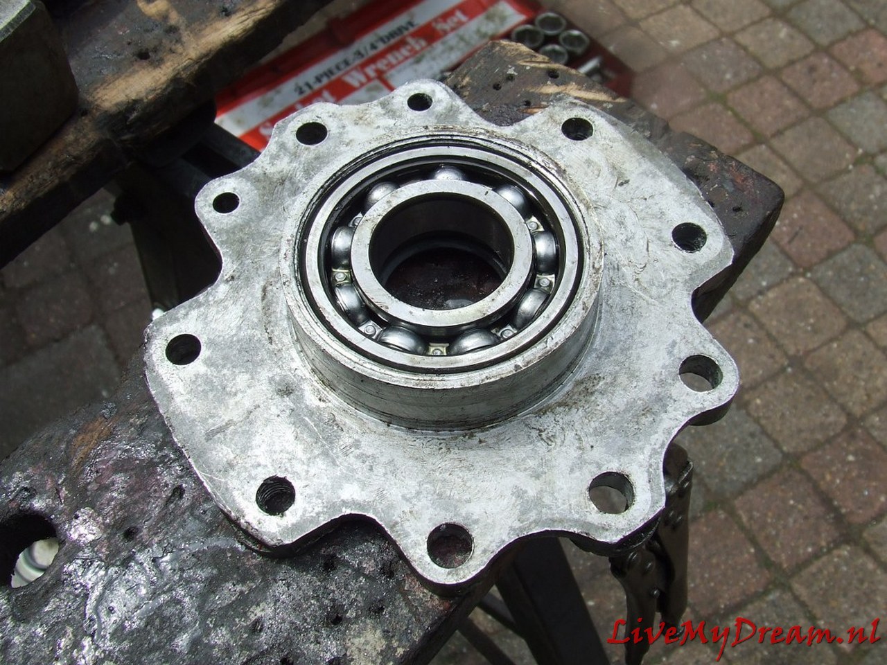
Bearing for the axle claws. I heated this part in the oven at 60 degrees before final assembly.
Ready.
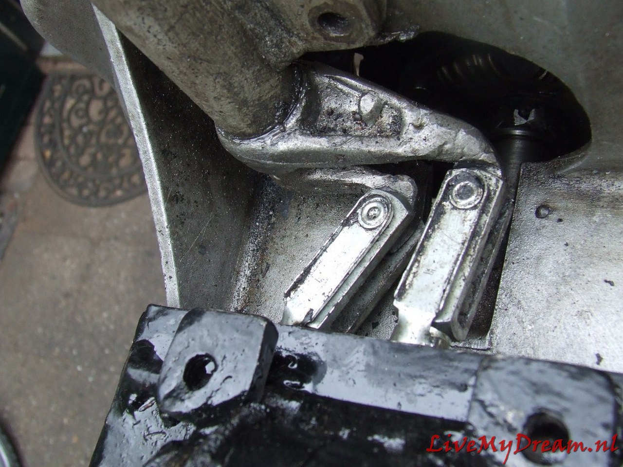
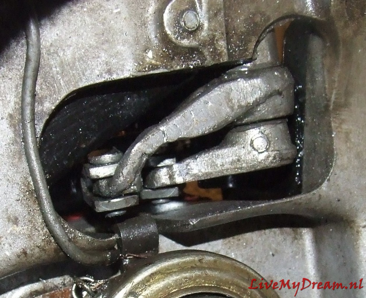
Shifting axles. Left the up/down movement of the shifter and right the left/right movement….
Taken during assembly: nut still tightening and all. At the bottom right you can see the sensor of the cruise control hanging away. The magnet is placed under the nut, which is still loose, with a bracket so that the recorder can see it at every turn.
Above the modified scoops of the underside of the switch tower.
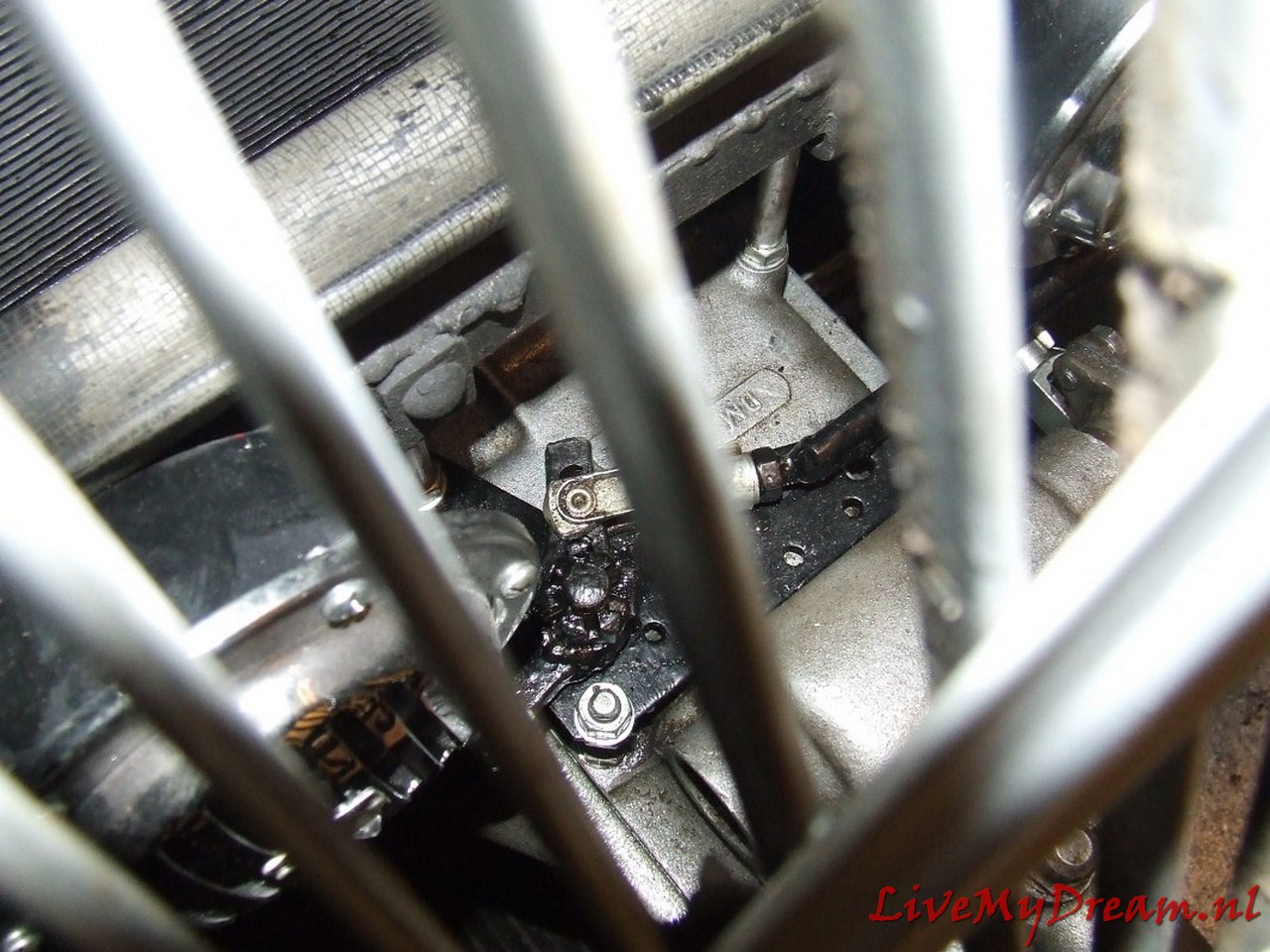
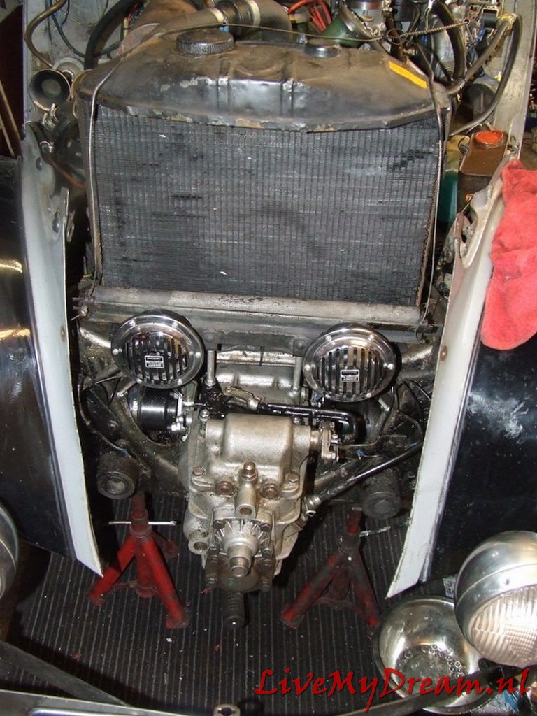
And- the final result!
Afterthoughts (2022):
Would I do this again? Certainly a YES
Would I do it differently? Also for sure a YES!
In hindsight I would include everything that comes from the ID into the Traction, which means the engine, bell housing and gearbox. You only need to shift the engine mounts in the engine bay somewhat to the front so the drive shafts are correctly poistined and make a properly attached connecting point to ‘hang’ the gearbox in the Traction’s cradle because this is different in the ID.
Of course, controlling everything is different like the clutch cable goes on top instead of left of the bell housing, you need to make new drive shafts, gear controls are new (like with any conversion to 4 gears) but that’s all doable.
Think of the benefits: Alls fits perfectly and you don’t need to get the gearbox off the engine nor off the bell housing. No difficult machining with fitting plates, lengthening primary axle, and so on. And- you get to keep our original set intact as-is so you can always revert this build to original, and very fast!
The simple truth is- on the other hand- that driving with an ID engine and 4-speed gearbox that I don’t want to go back to the 3-speed gearbox. Ever. Unless it is needed when the car gets sold. I do have a complete original set available as spare with everything on it. I run it every one and a while but in practice it is more of a stand in the way than a serious neccessity.
The drive shaft holders still need to be shortened but they will fit perfectly back in place again, on their original position.
Maybe I will get lucky someday and get the opportunity to obtain another engine/bell house/ 4-speed gearbox combination but this stuff is already very difficult to get this. No more surprises or people that almost ‘give’ their old cars away..
I am still pleased with what I made, though. And it drives very well!