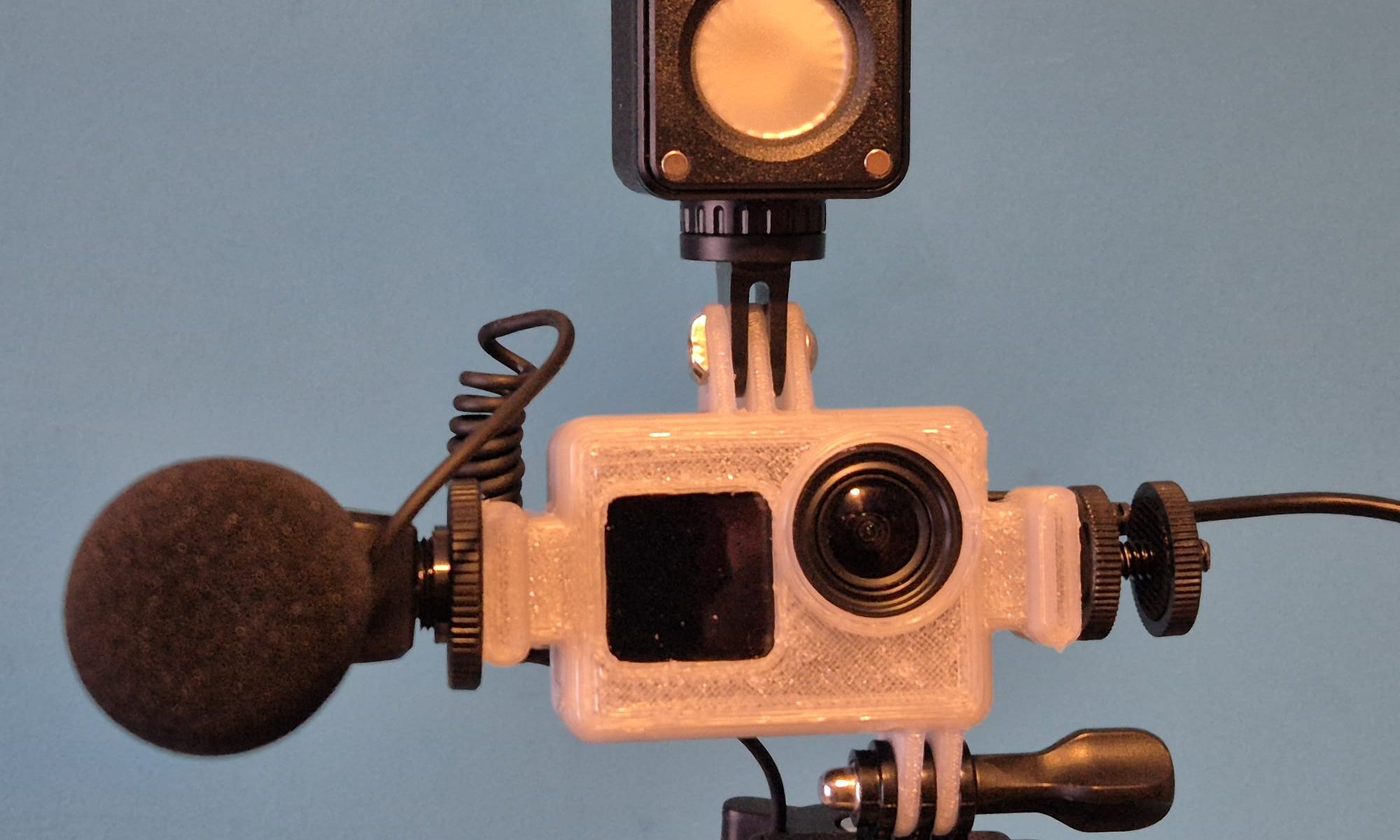
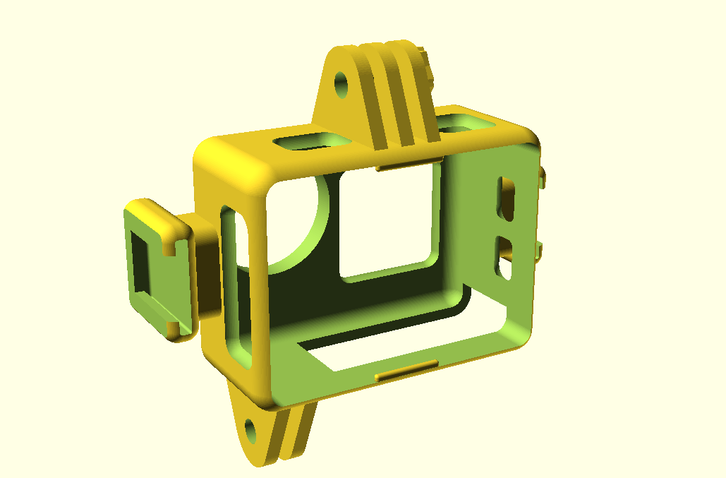
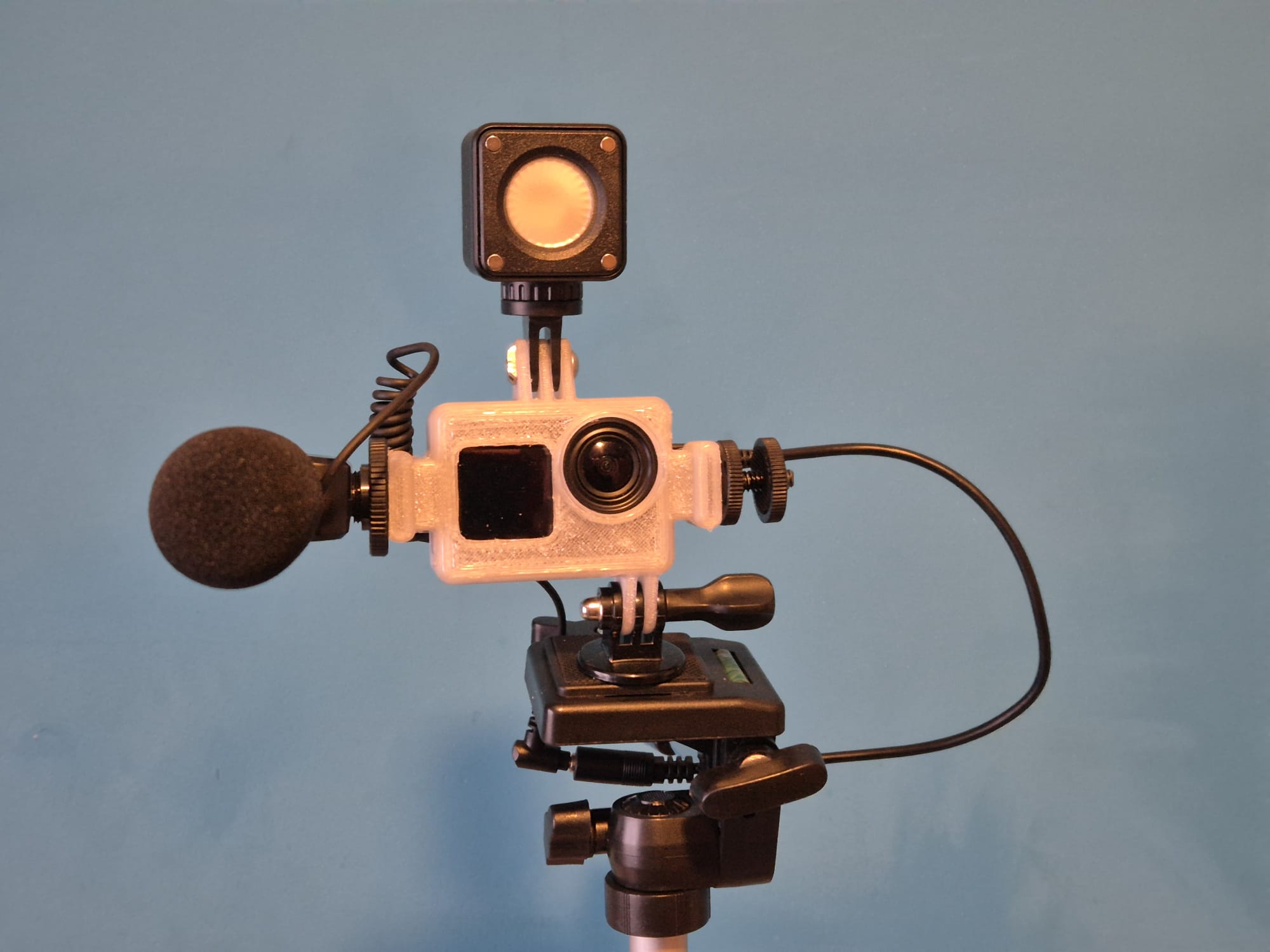
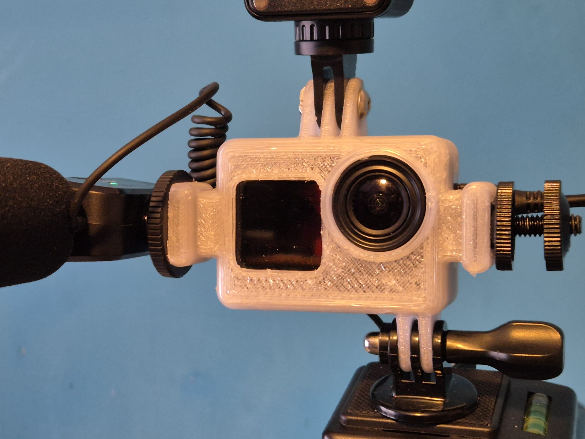
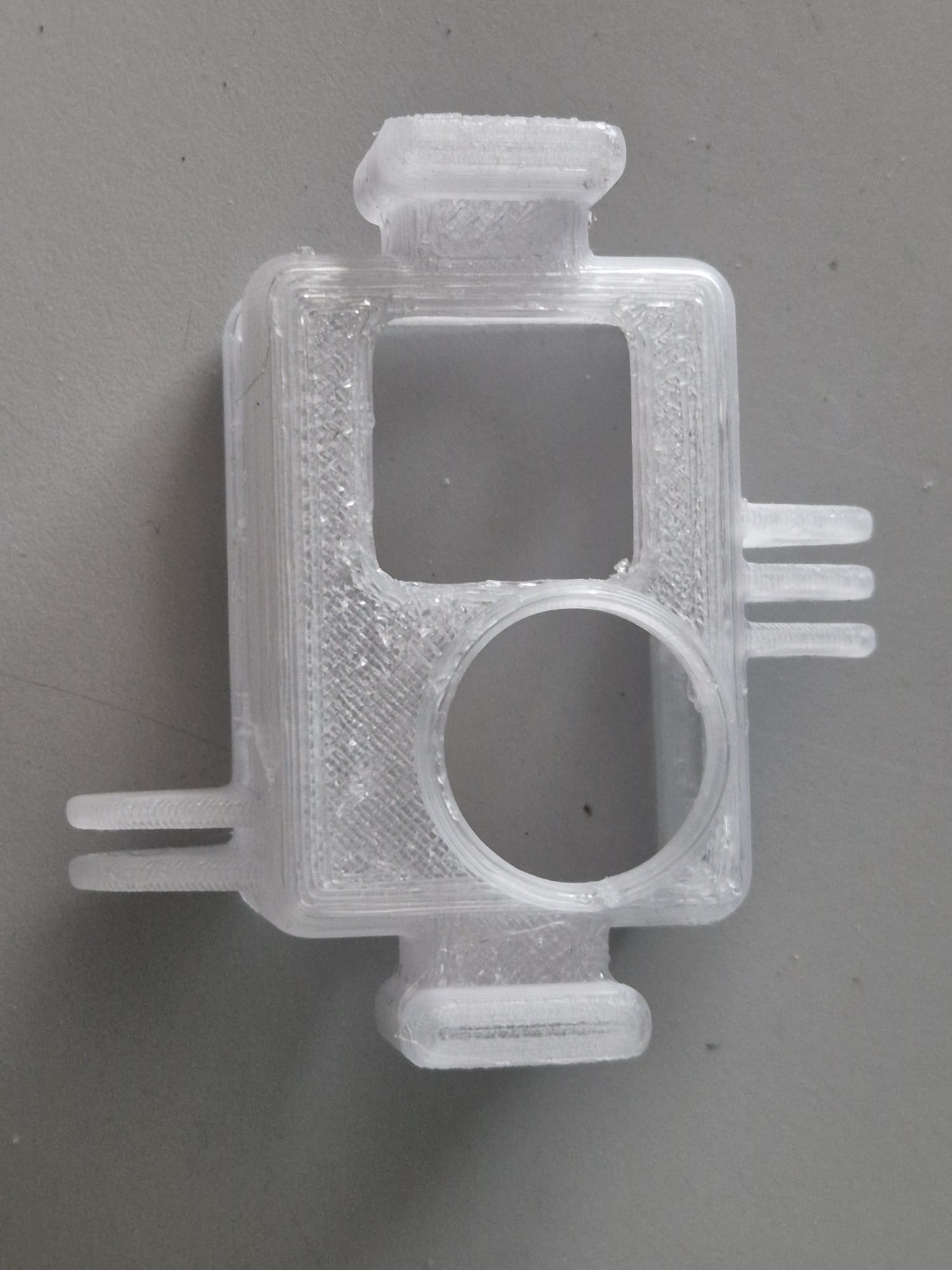
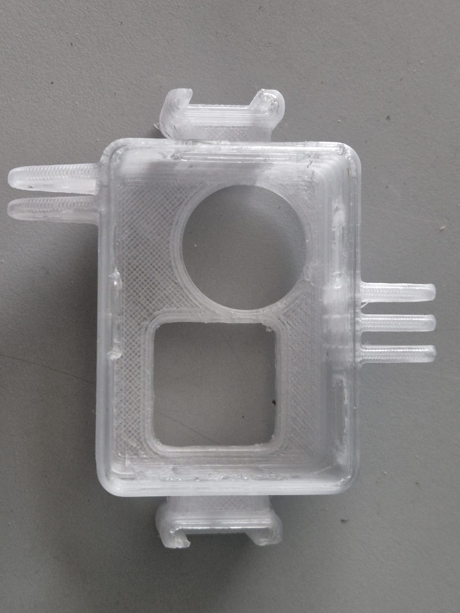
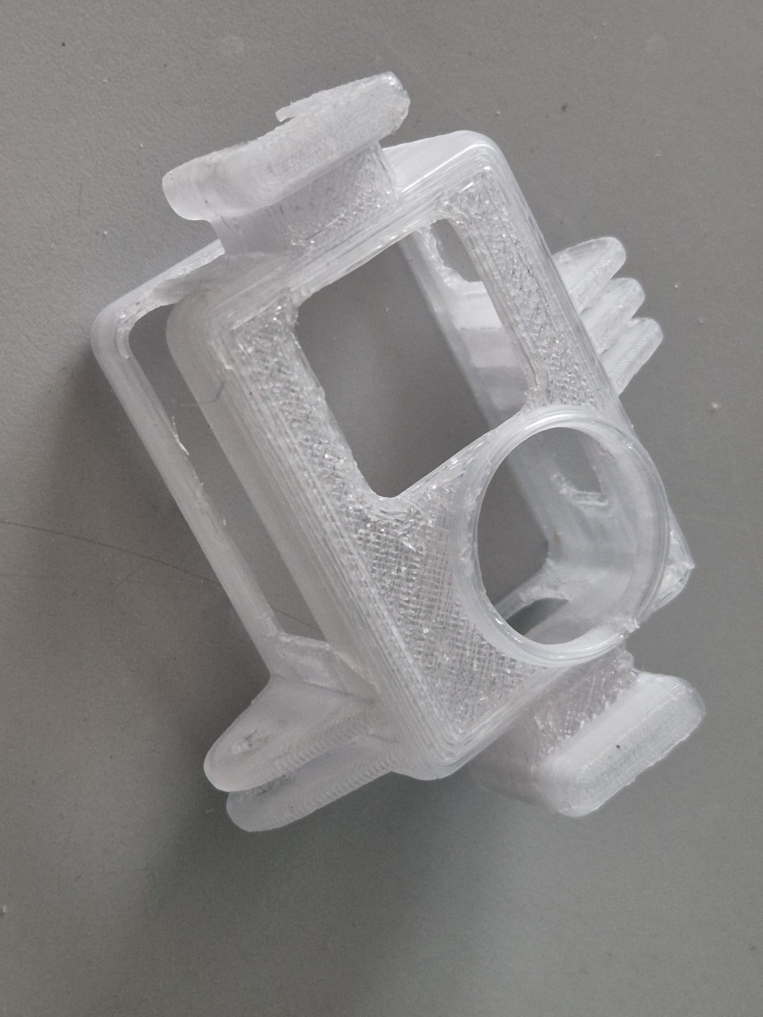
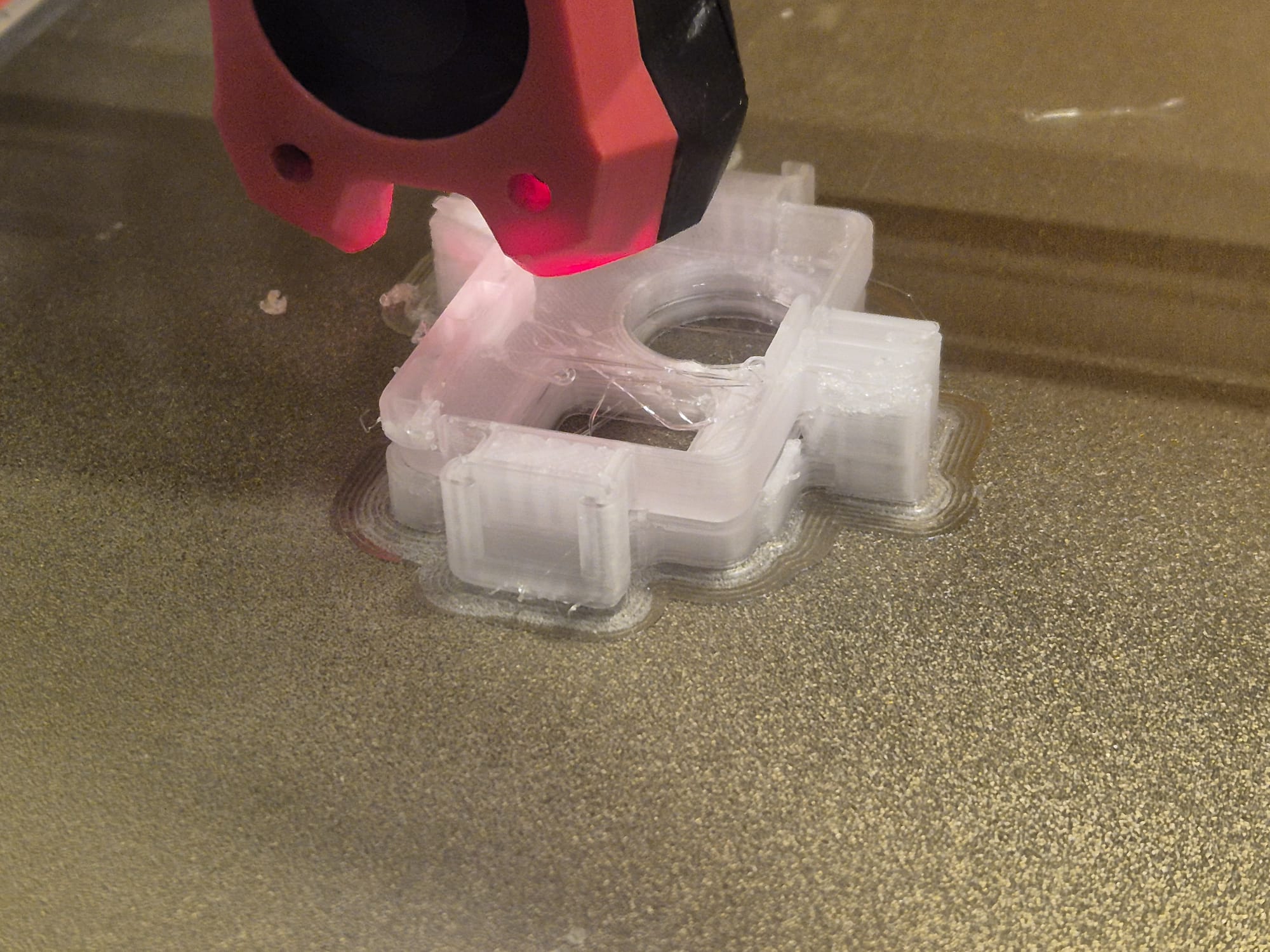
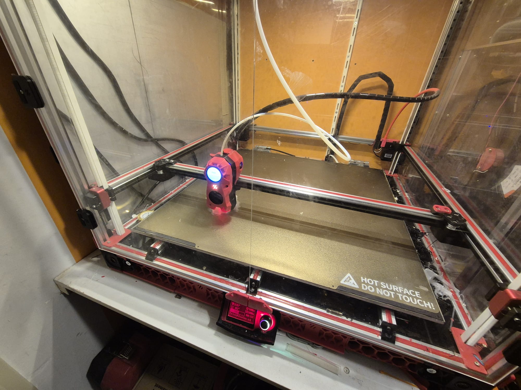
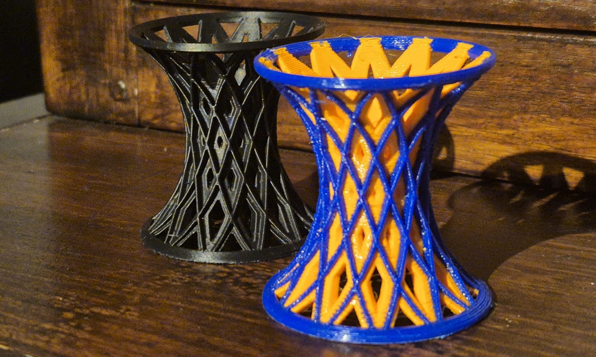
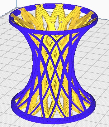
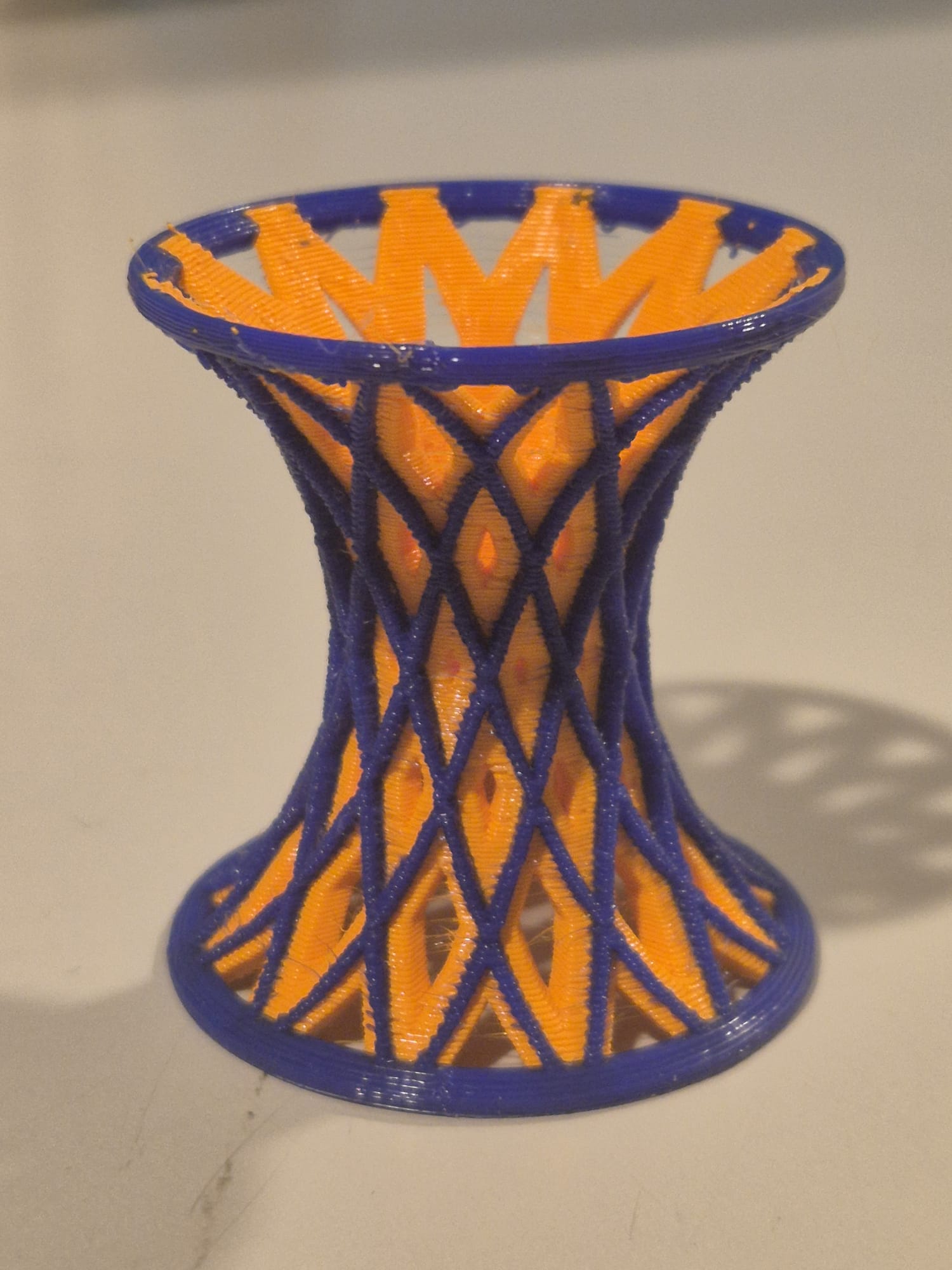
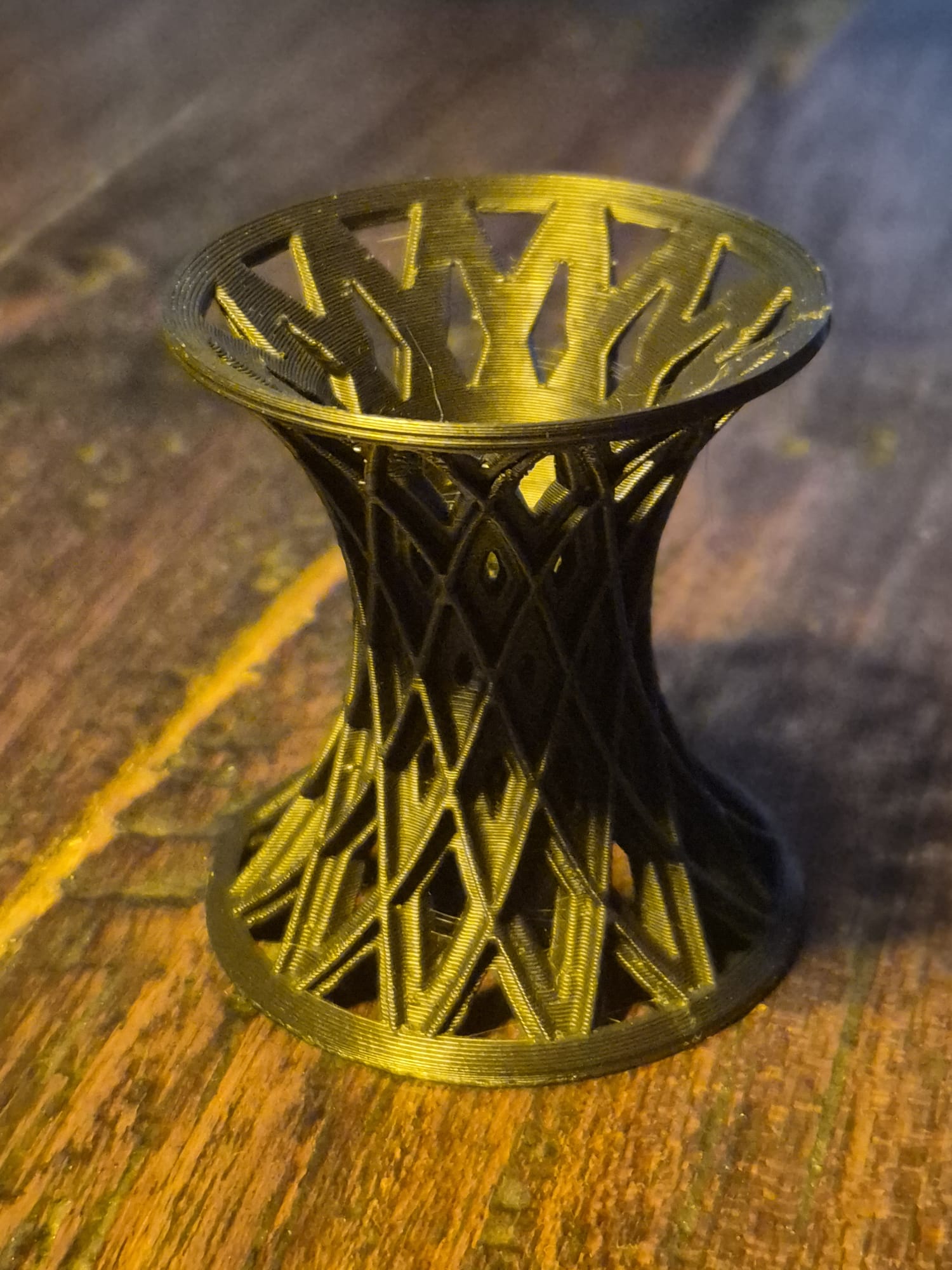
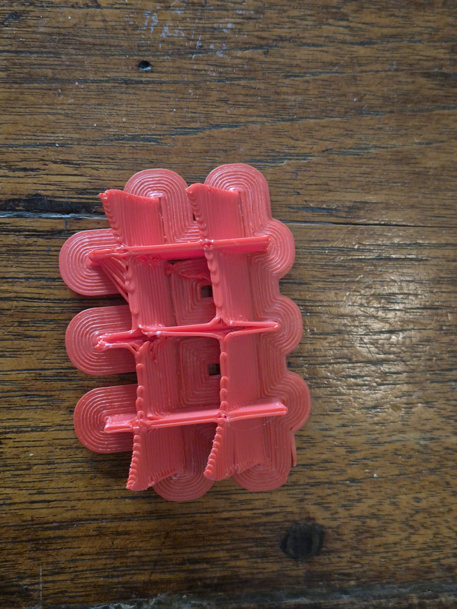
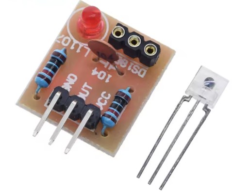
Printed on Voron 600 @ 0.3 mm LH and 0,8mm nozzle, transparant PETG. Hispeed in 1 hour at 100% infill, front down, brim 0.2 mm thick, 10mm wide. Supports everywhere in matrix mode @ 10mm wide, big gap 0.5mm top of Z and 1.2 mm on X/Y spacing. Temp 235 deg nozzle, 85 deg bed. 100% fan except for 1st 3 layers.
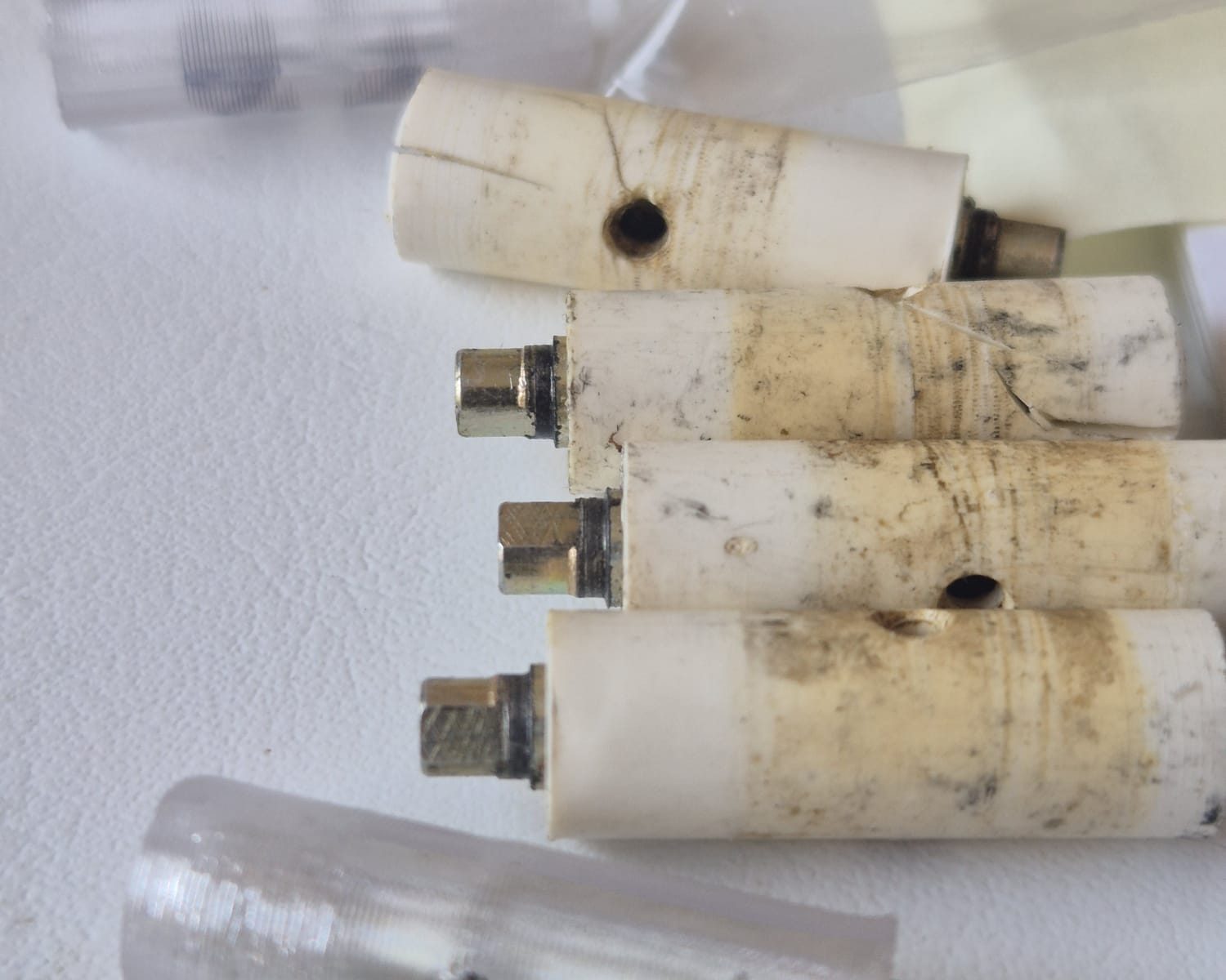
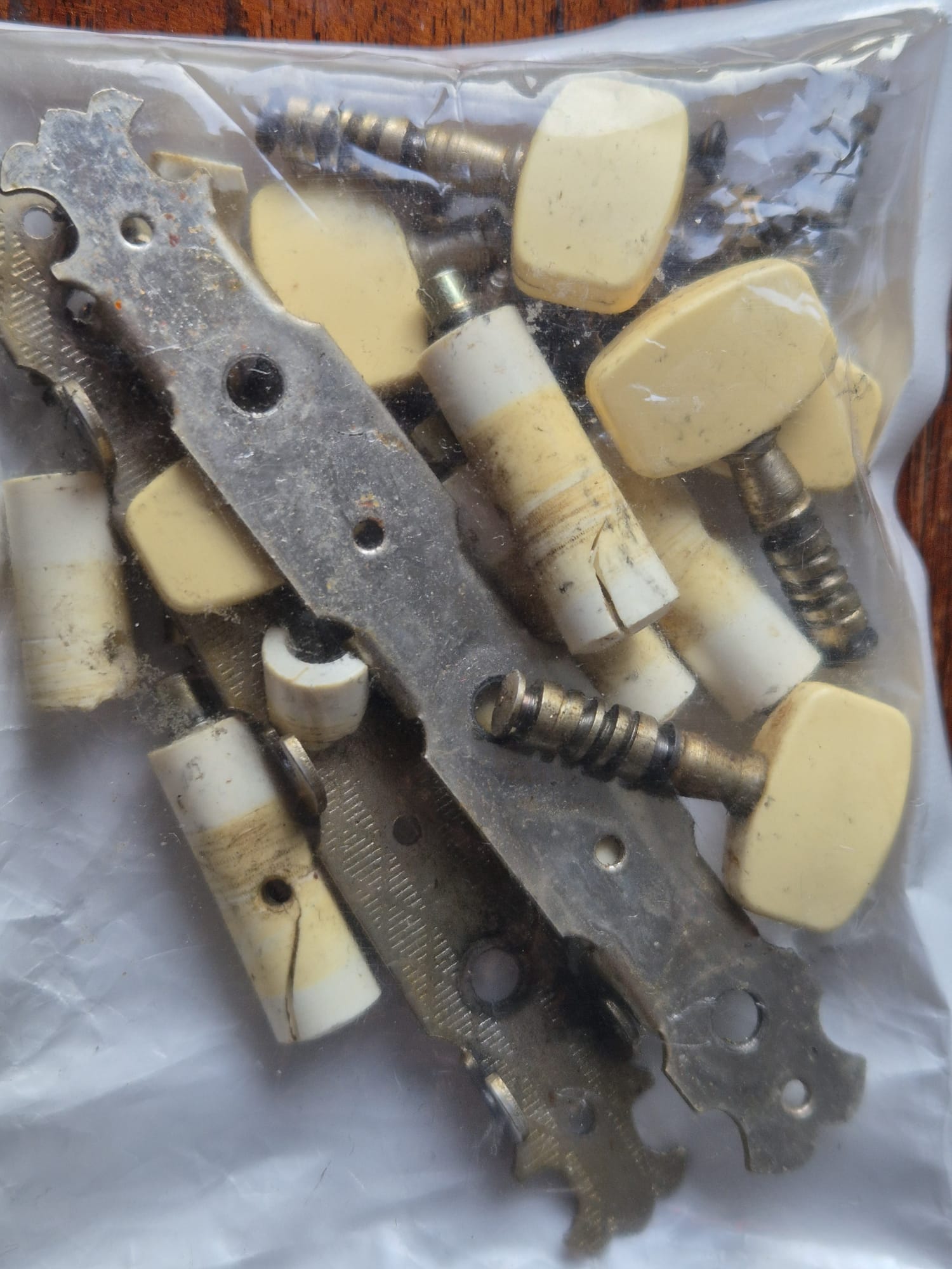
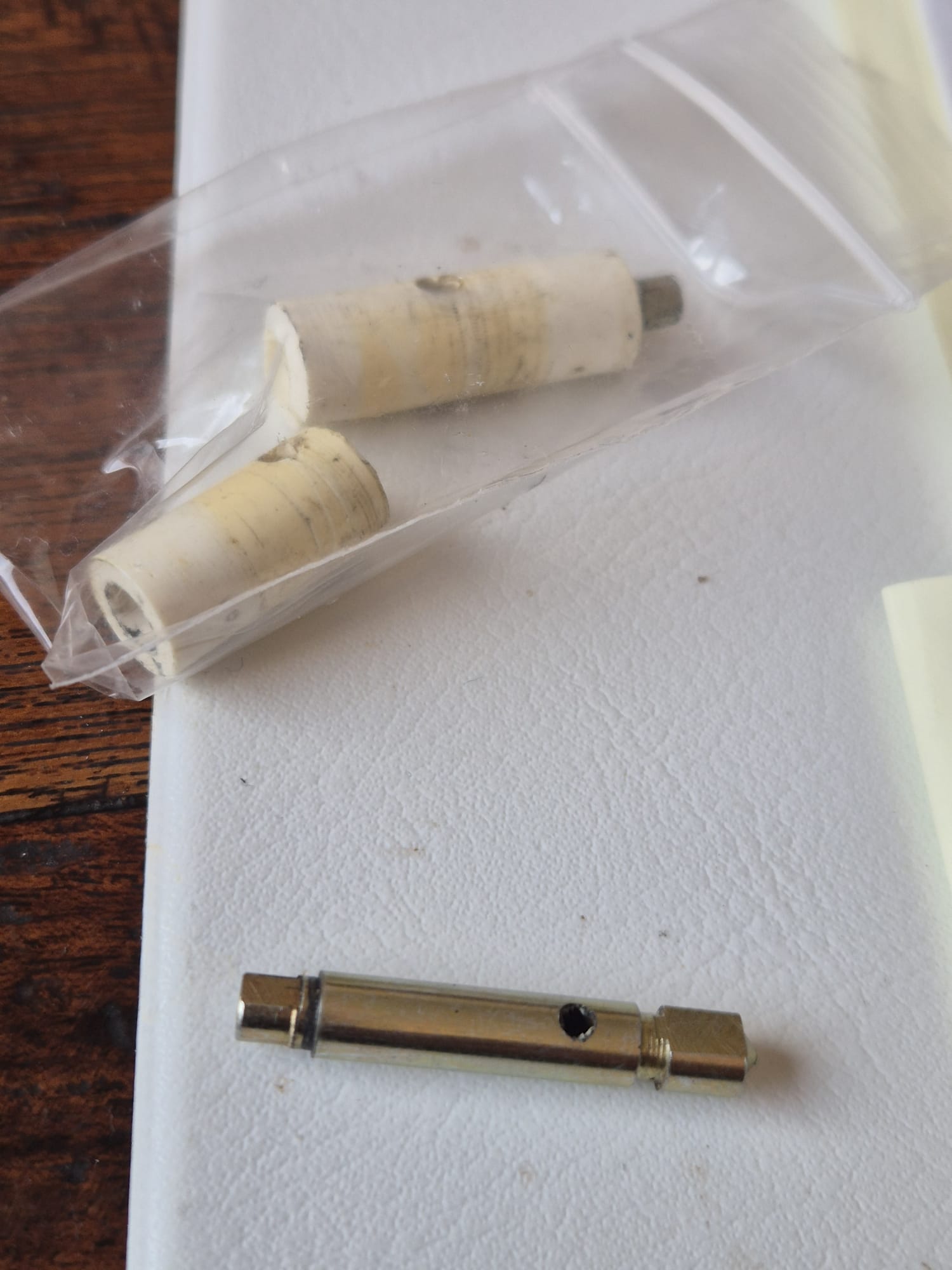
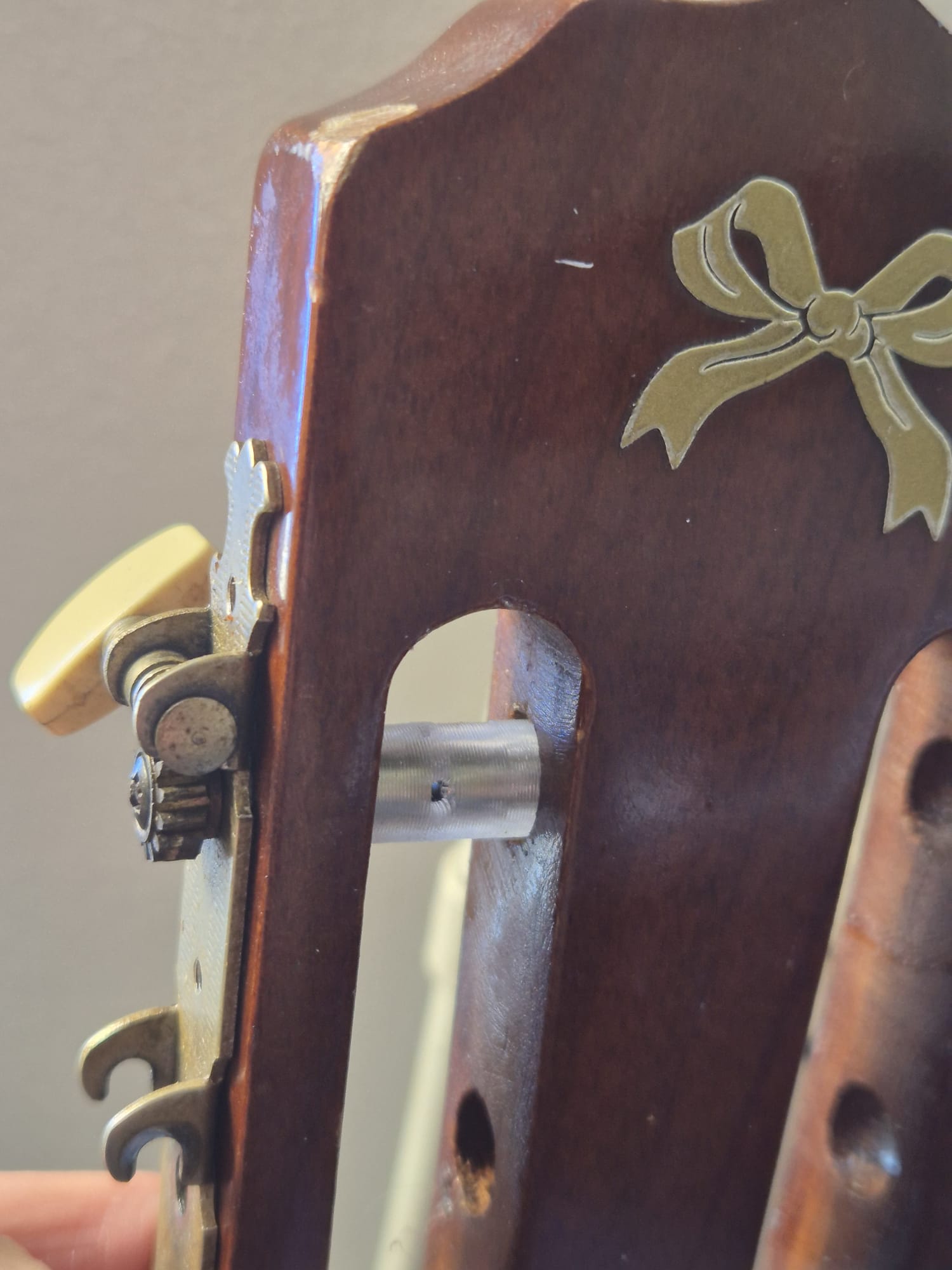
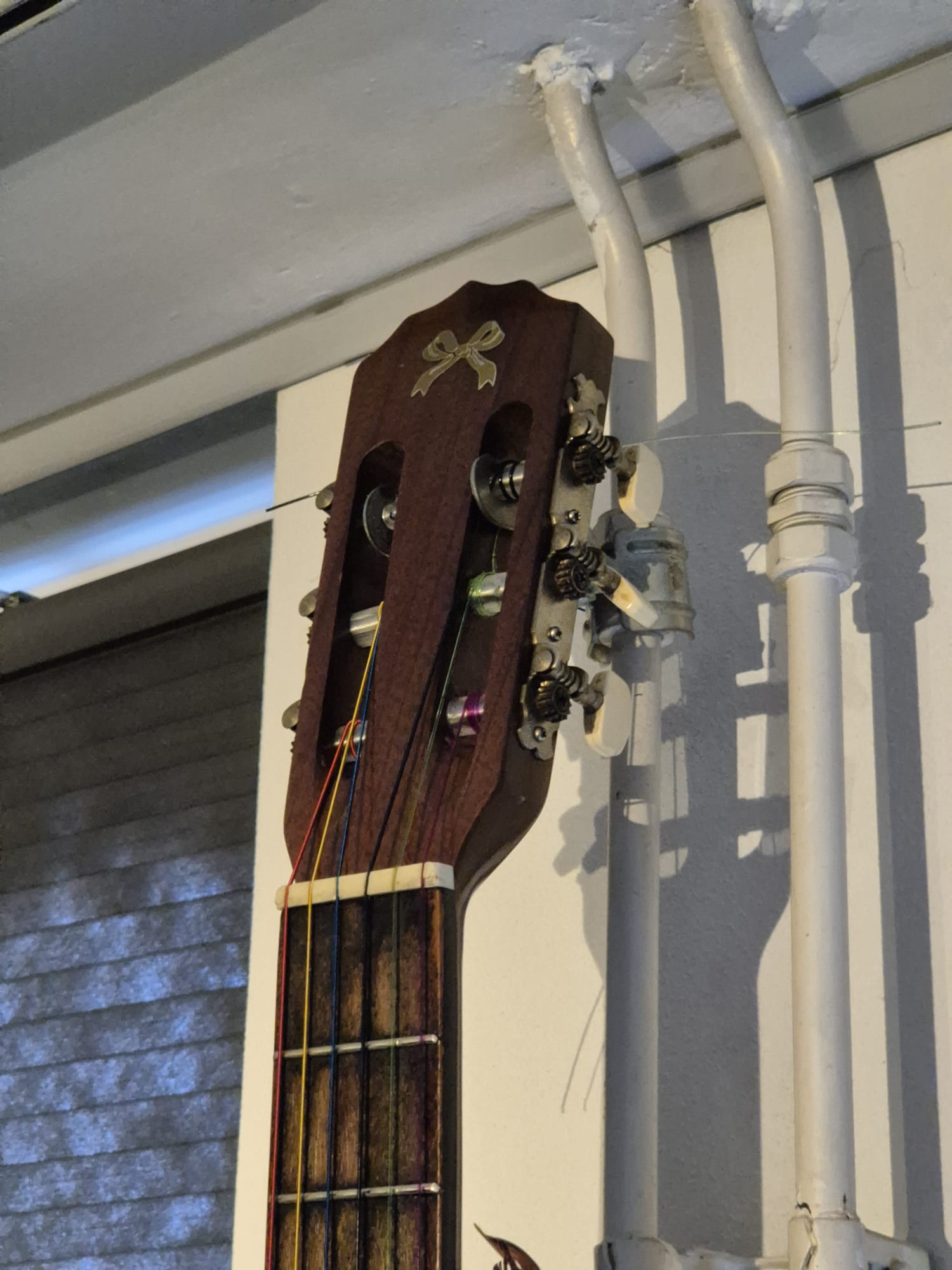
One of my very old DIY elktro-acoustic guiters had broken tuners on it. I did not want to order me new ones, since the mechanics were Ok, it was just the plastic covers that were all more or less torn up.
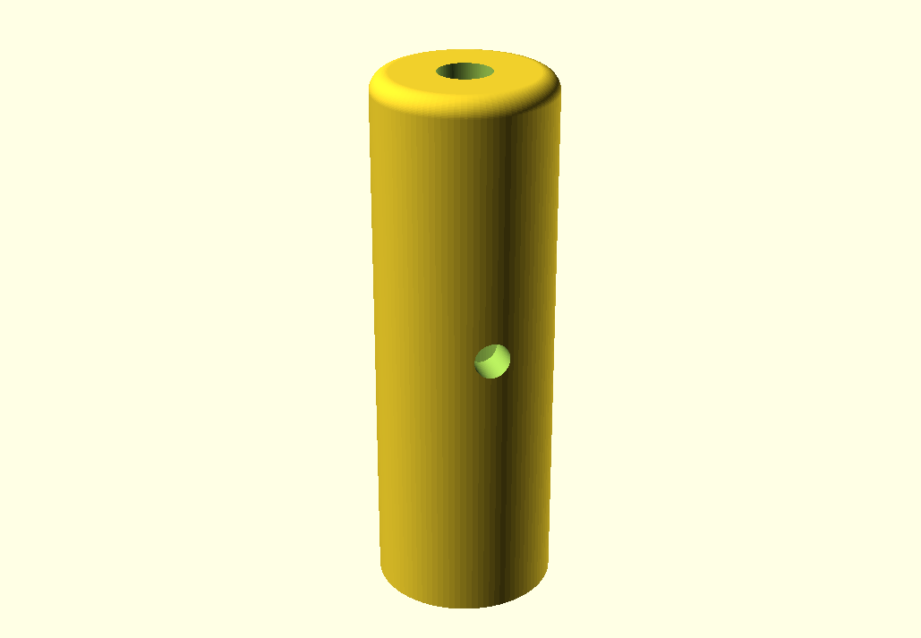
In Openscad, I designed the to be 3d-printed sleeves that fit around the metal tuner shafts.
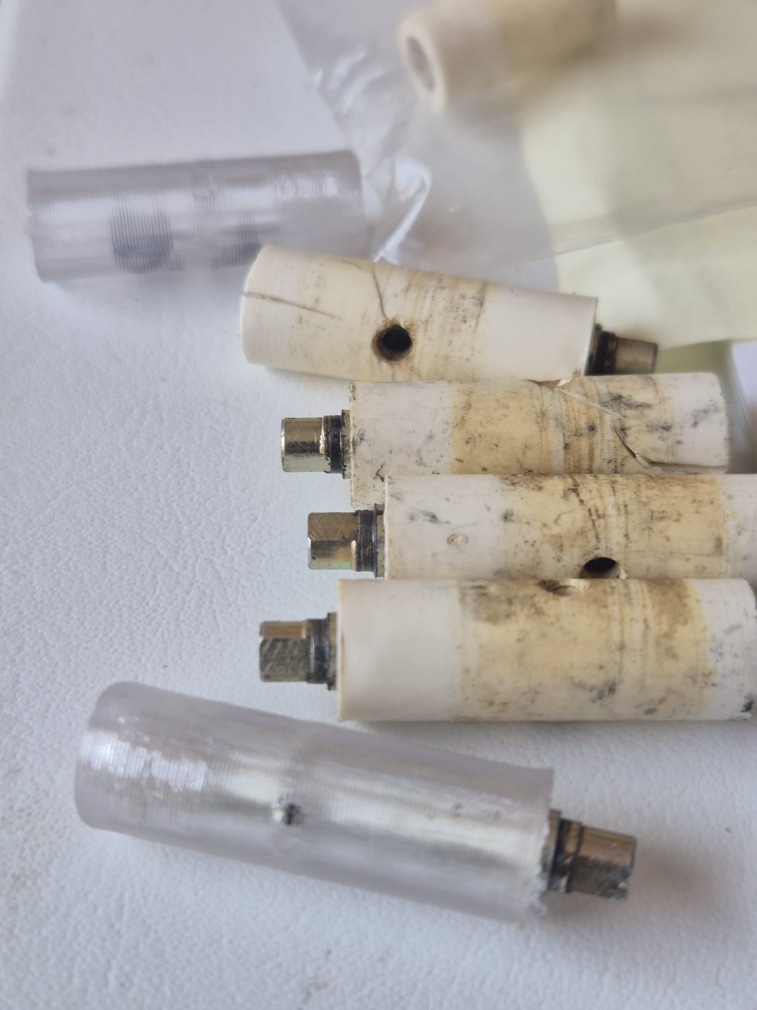
I printed 6 sleeves in transparant PETG on the Voron 600 (0.8 mm nozzle, 0.3mmLH, 235deg nozzle//85deg bed.
No supports, although I did use a firm brim around the shaft. I printed the sleeves one at a time, in 7 minutes each.
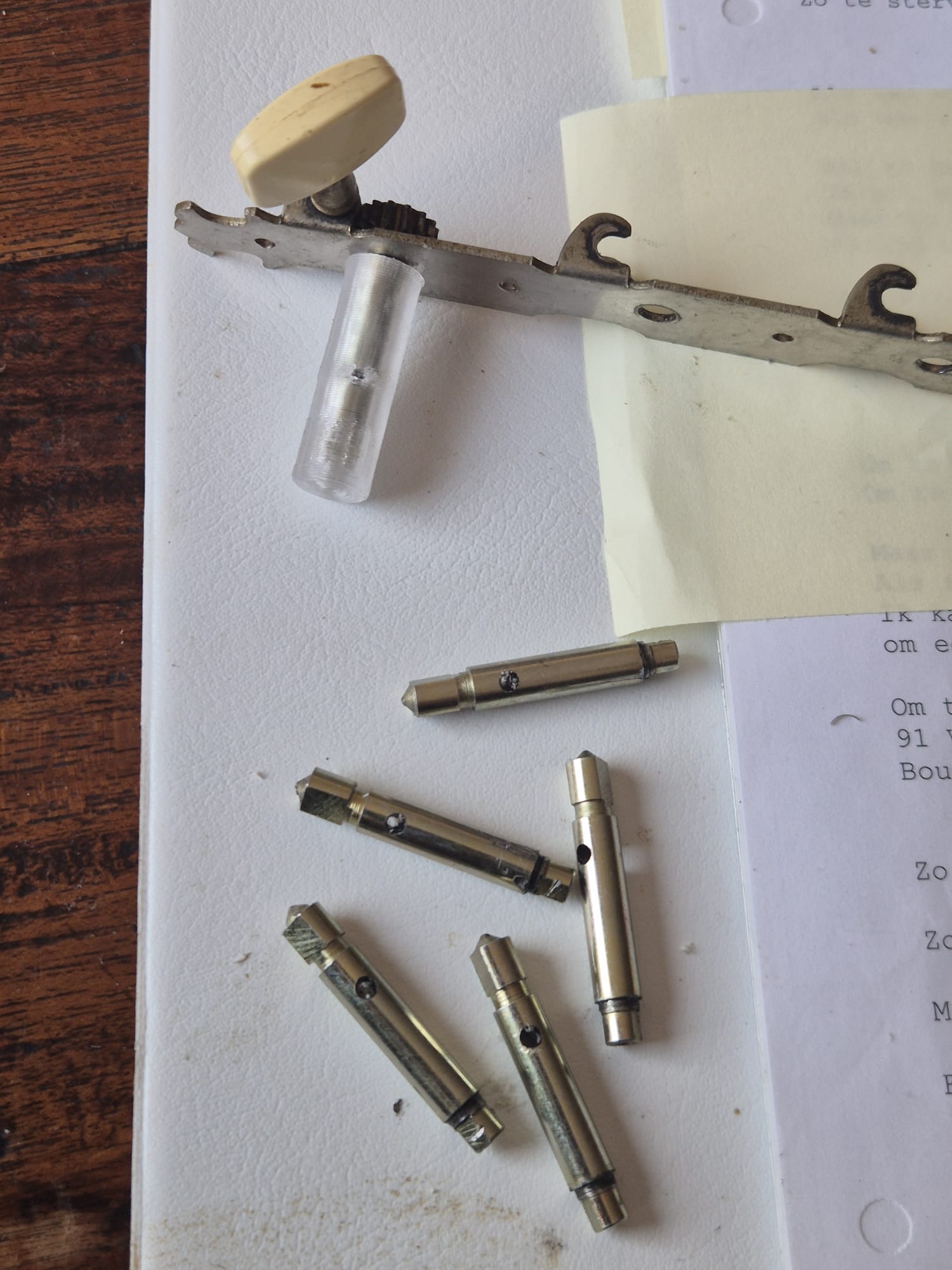
The old shafts were tapped out of the metallic shafts. I used my vice and opened the vice’s jaws just enough to tap the shafts out of the sleeves.
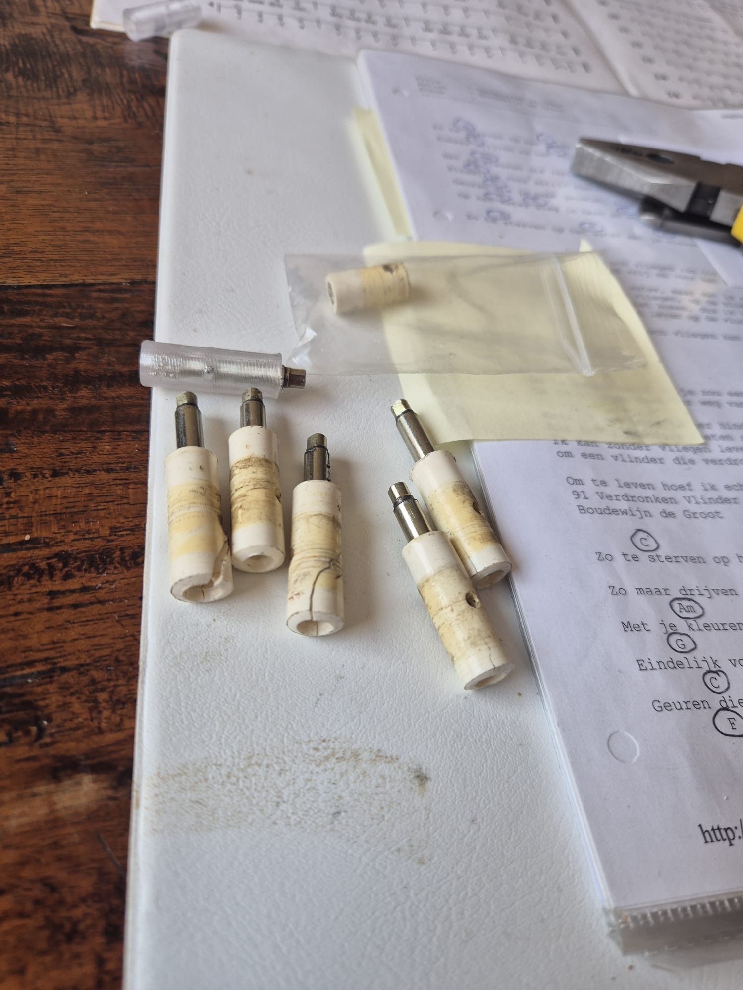
Mounting the sleeves around the shafts is pretty easy, since the hole in the shafts and sleeves can be lined up due to the transparancy of the PETG material.
The shafts fit easily in the sleeves, although I used the vice to push the shaft in for the last 1-2 cm, due to the tight fit of the shaft in the inner sleeve’s recess that makes the sleeve follow the circular motion of the shafts when tuning the strings.
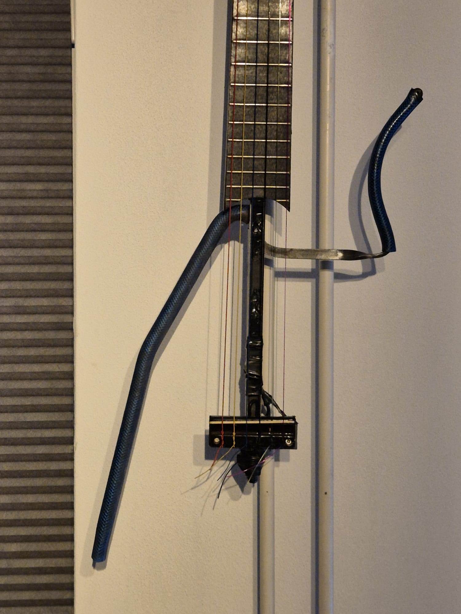
When installing the tuner sets, I used some vaseline around the plastic sleeves where they meet the holes in the tailstock wood so the sleeves don’t get stuck.
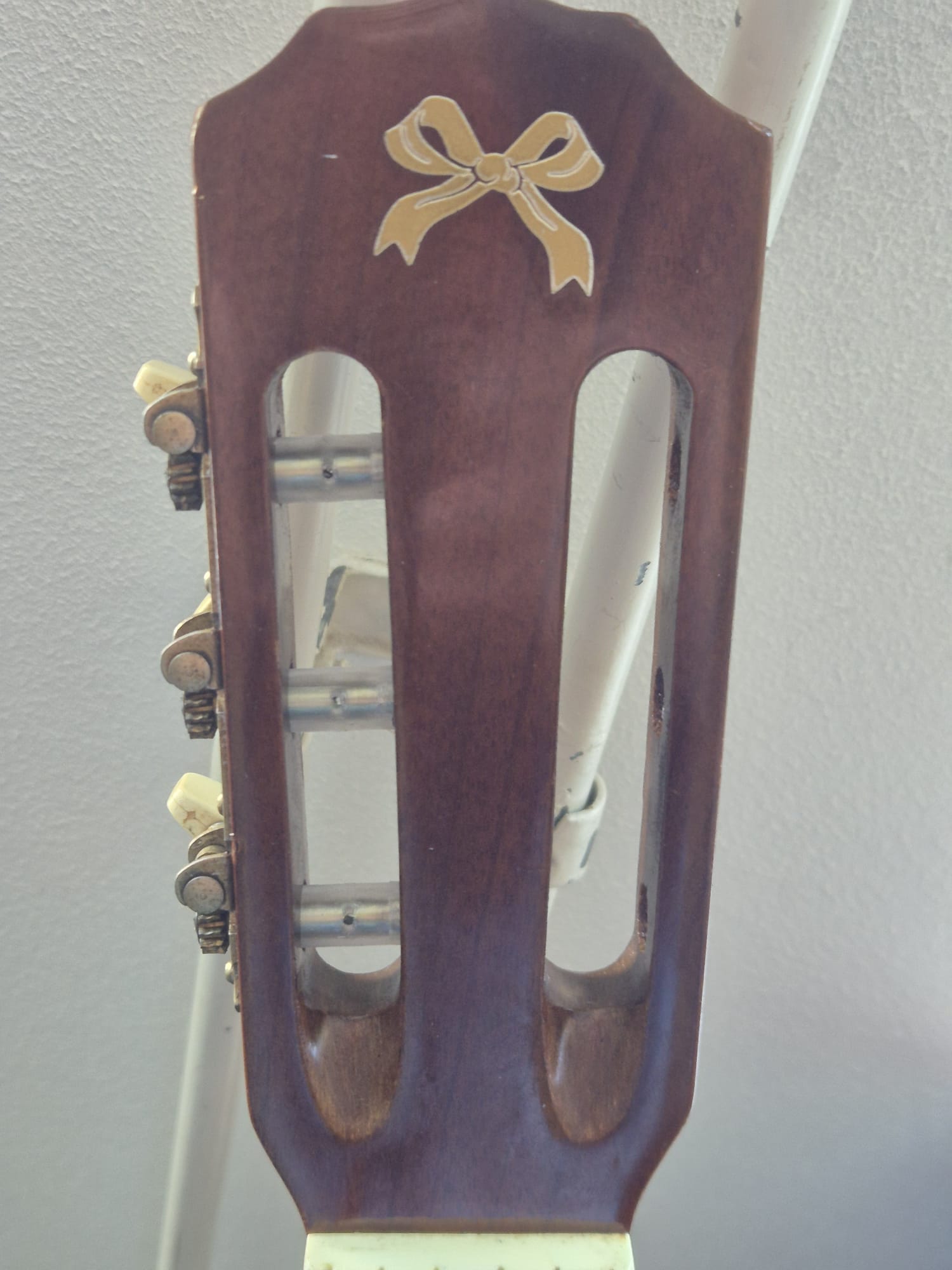
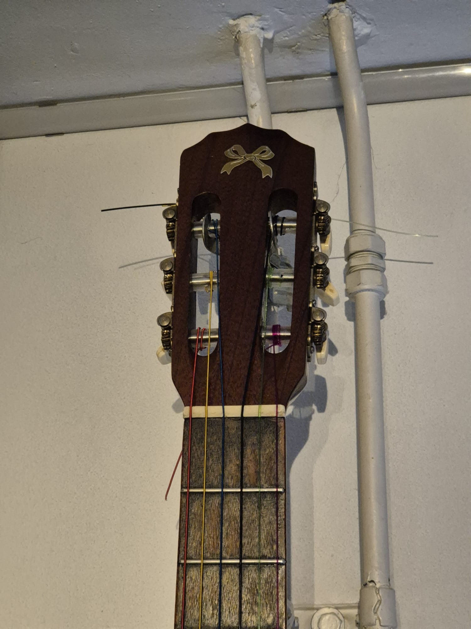
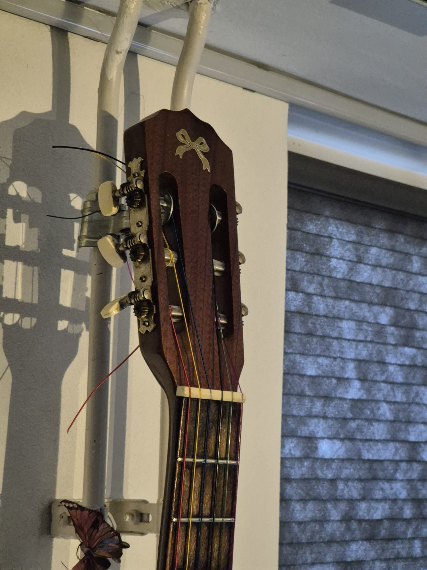
The process of de mounting and mounting the sleeves and the tuner sets is pretty self-expalinatory, please have a look at the below added photo’s!
BTW, I made 2 versions of the sleeves.
The one I used on my fast Voron600 is a bit wider inside (shaft diameter +0.4mm) .
This is needed due to the fact that little holes are always printed smaller on my Voron600 with the 0.8mm nozzle than designed.
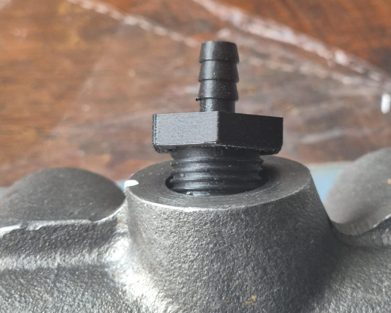
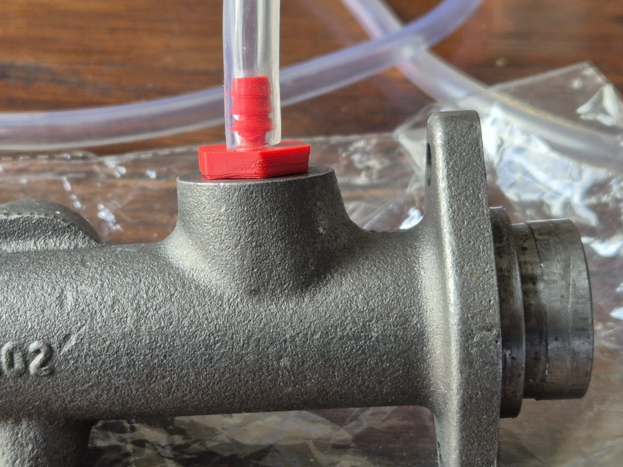
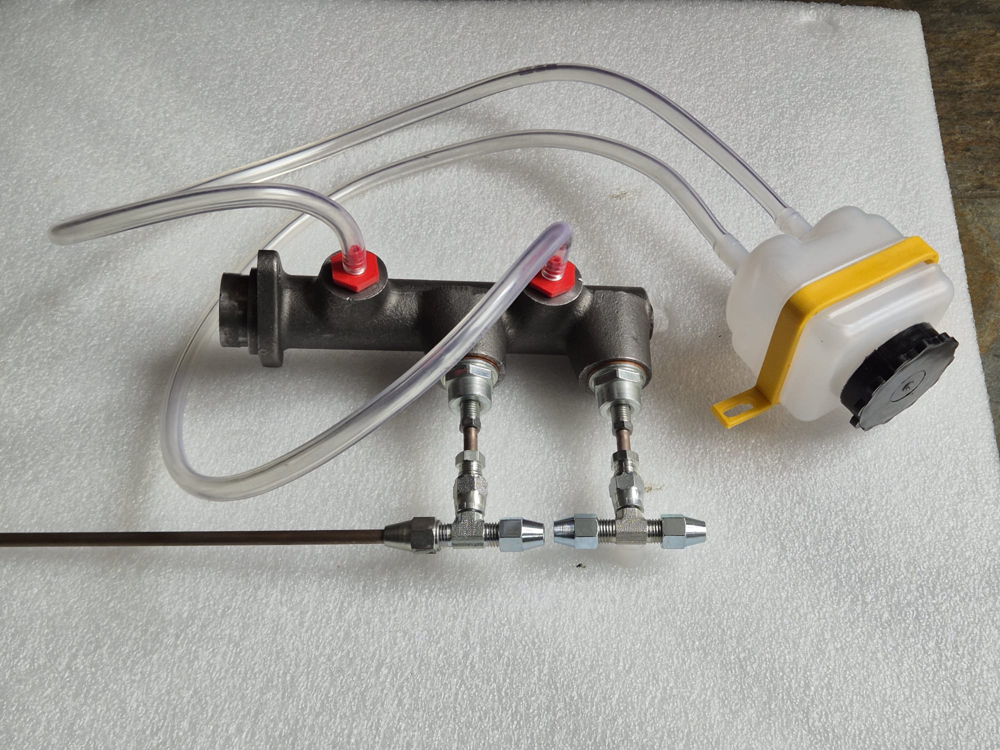
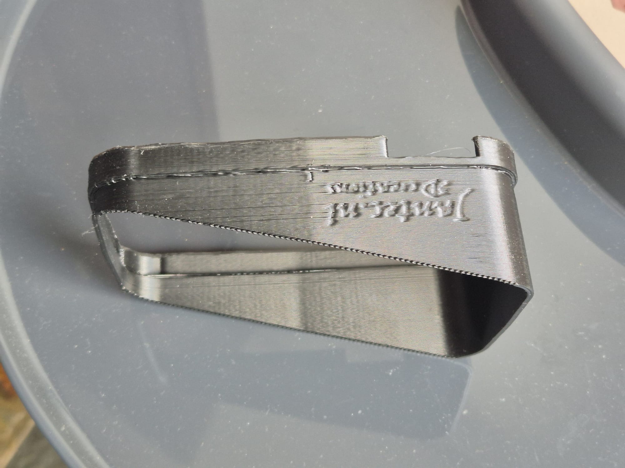
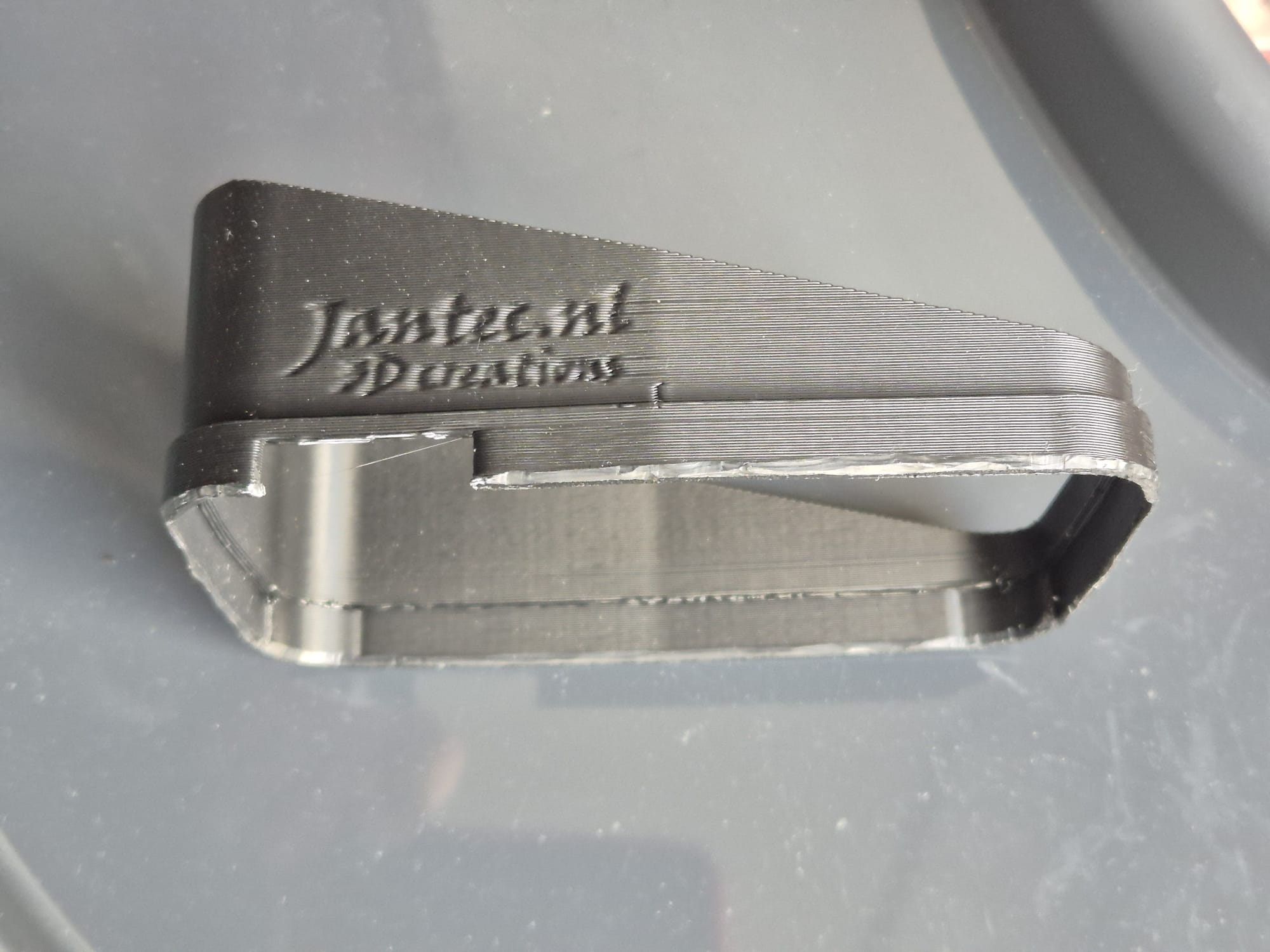
Made for old Peugeot J7/ 404 etc. and Citroën Traction Avant master brake cylinder, connects to a modern hose from a new type brake fluid’s supply reservoir. Printed in ABS, 100% infill. Put a rubber ring under the screw!
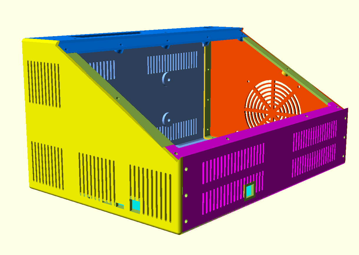
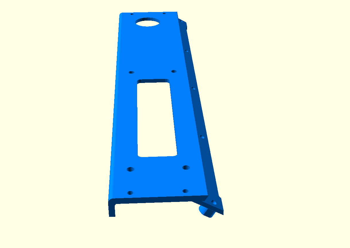
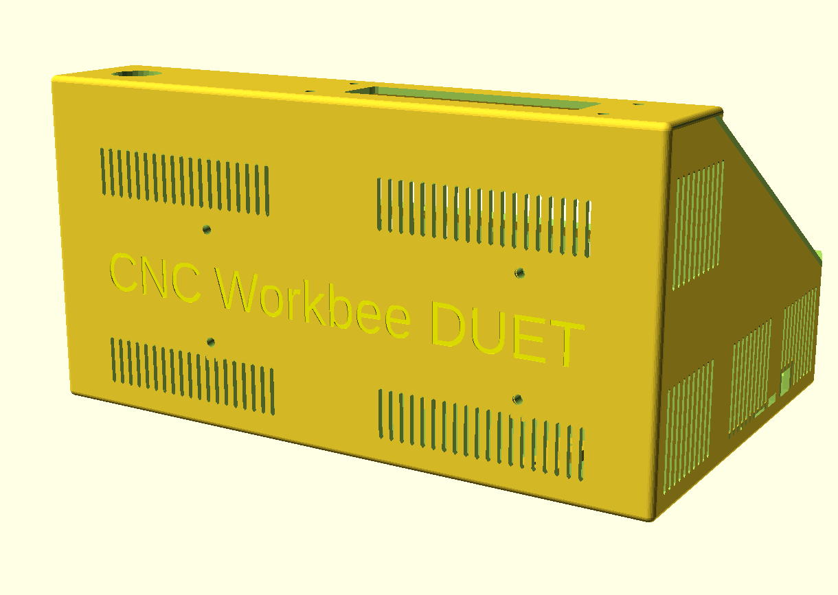
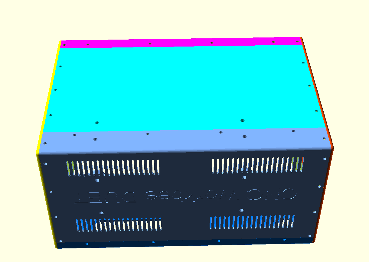
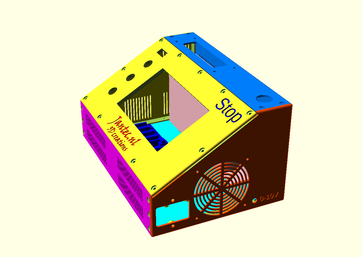
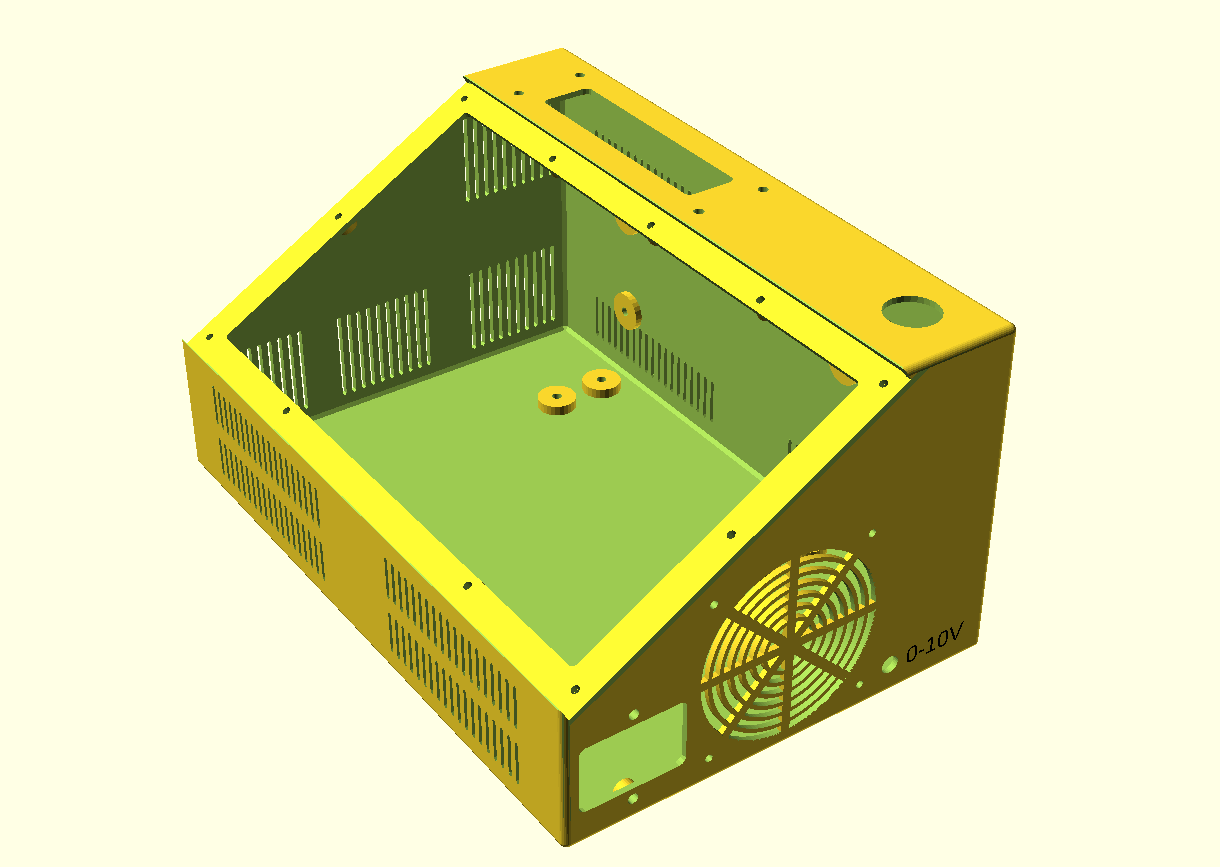
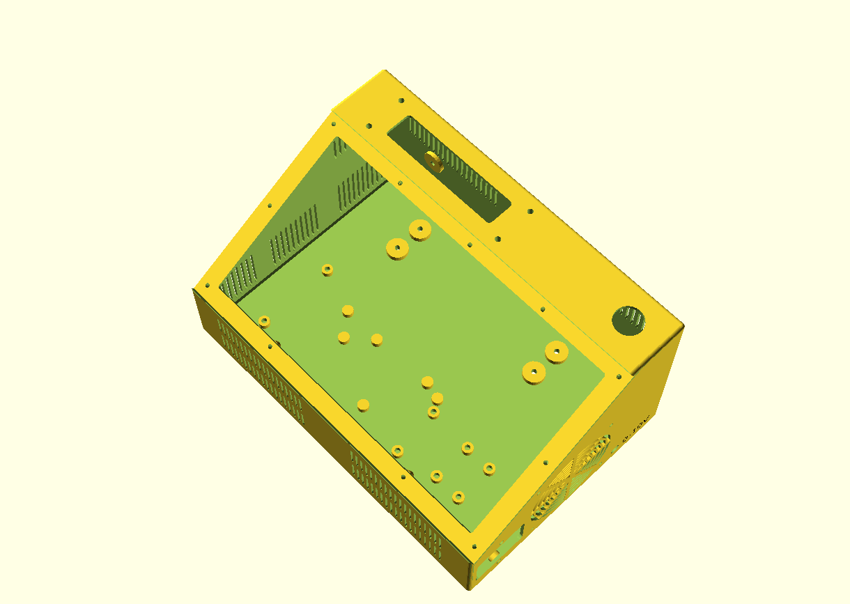
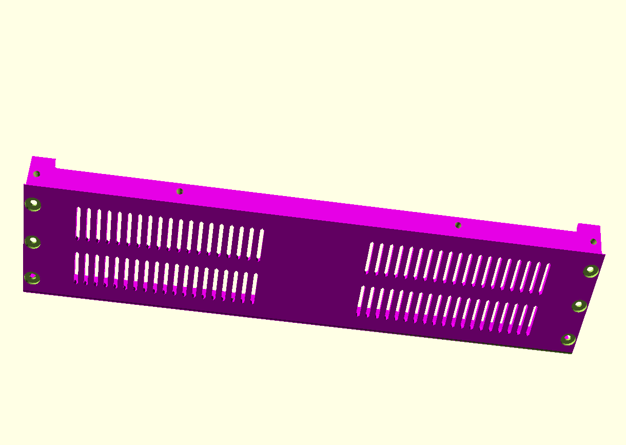
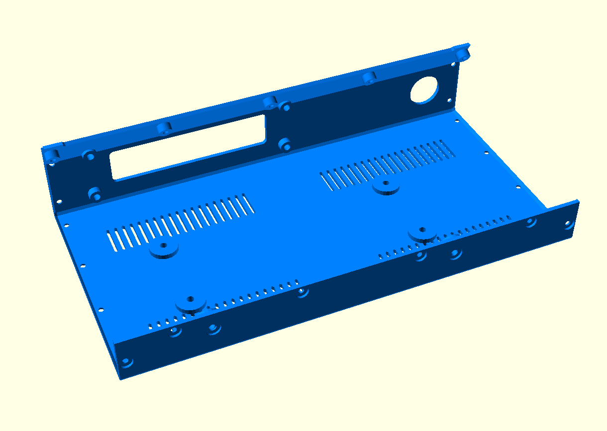
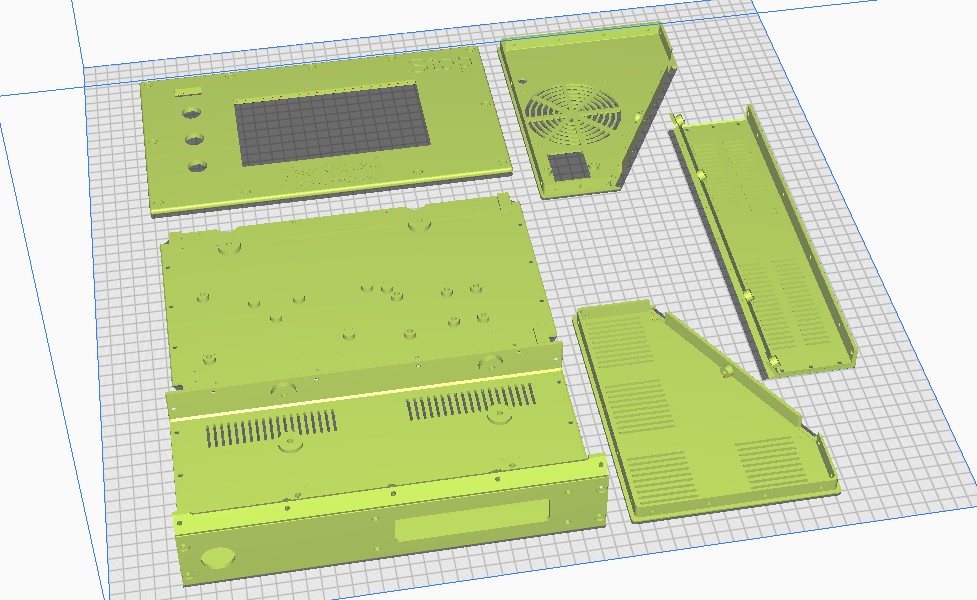
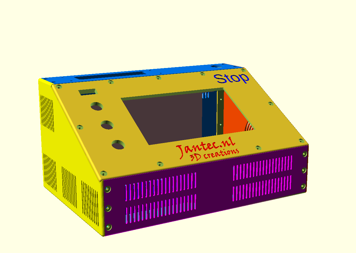
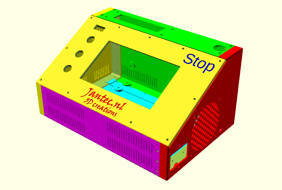
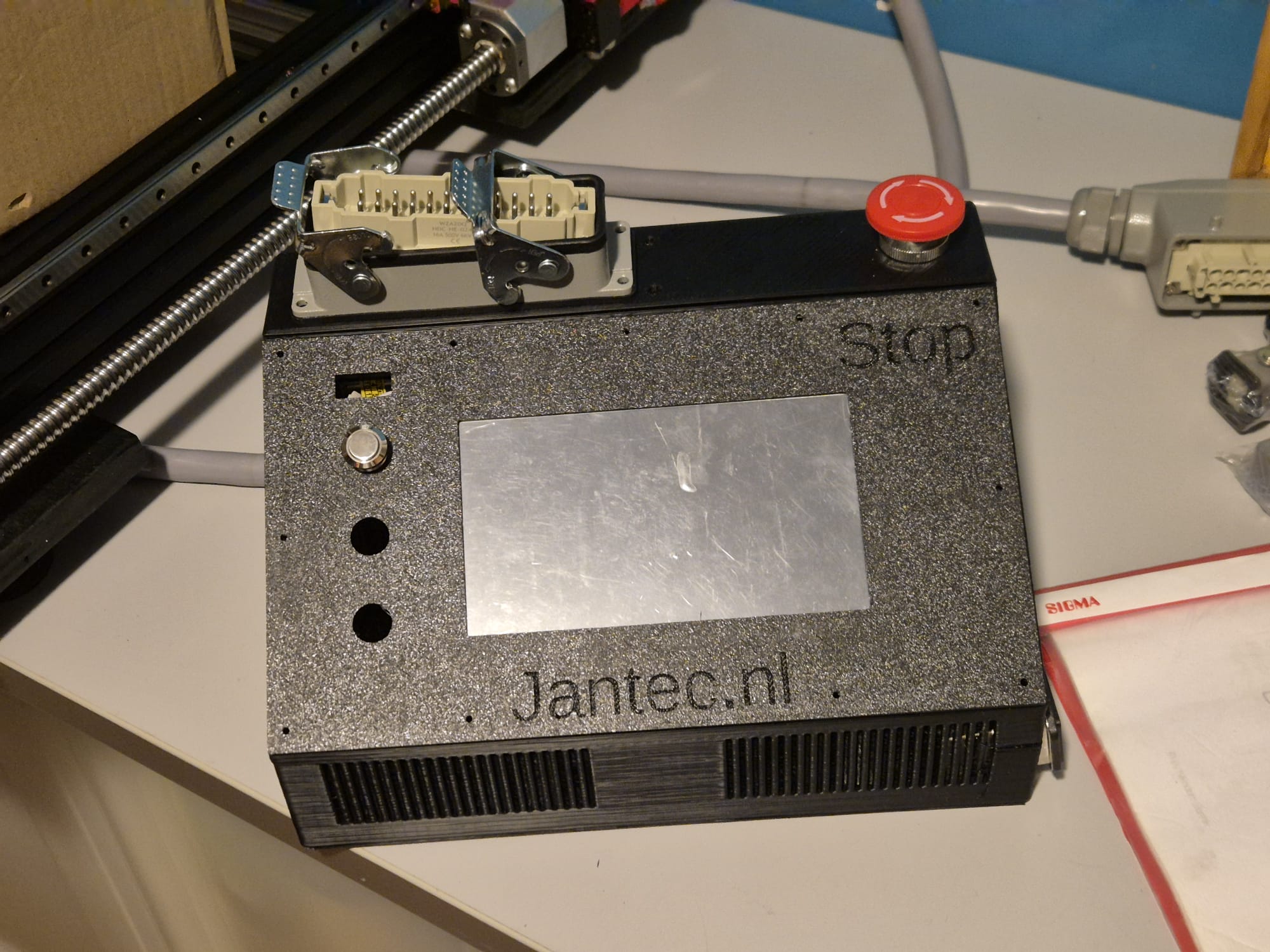
Download the CNC controller box design file via the above link in 1 piece which will take around a day or more to print.
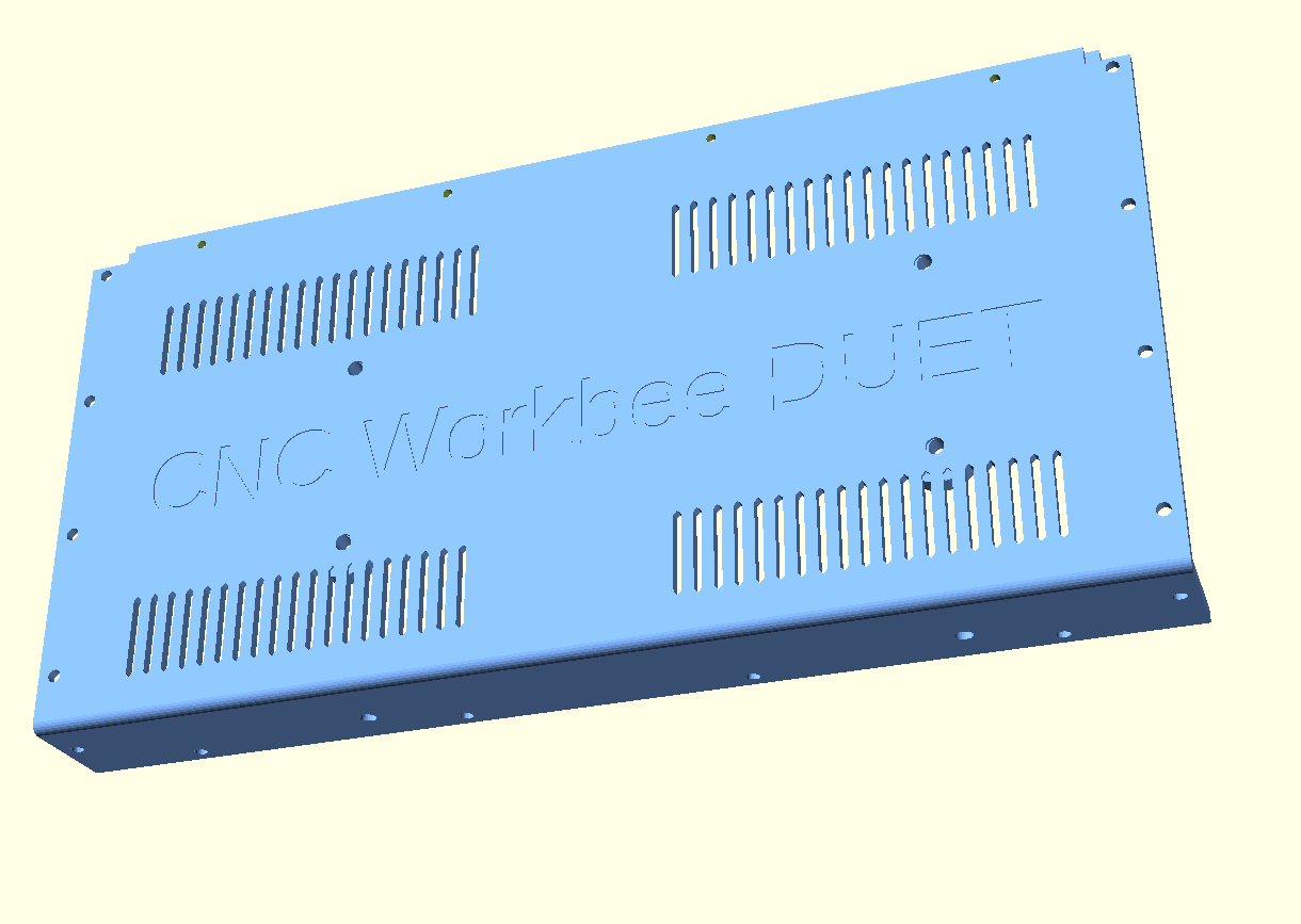
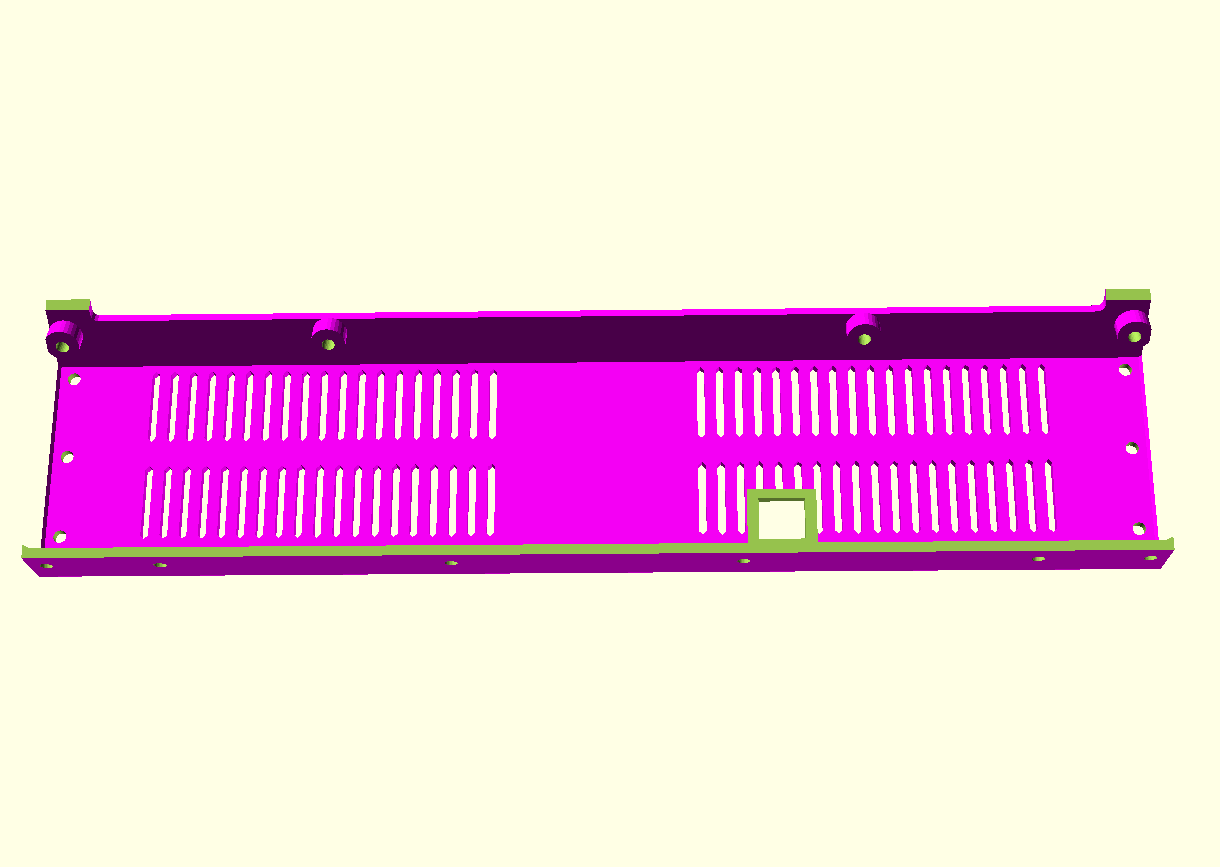
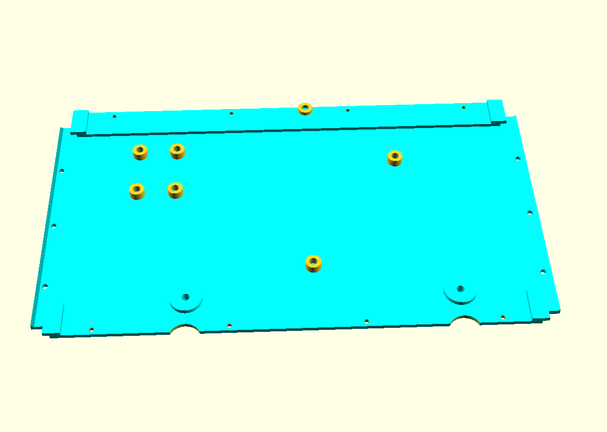
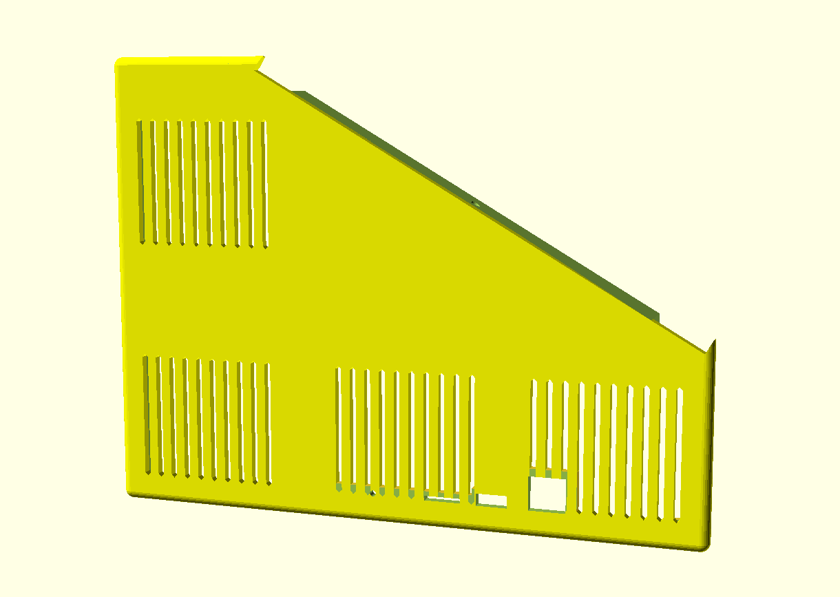
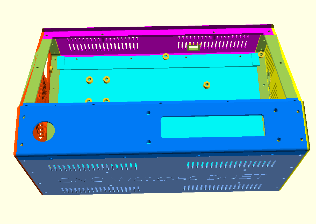
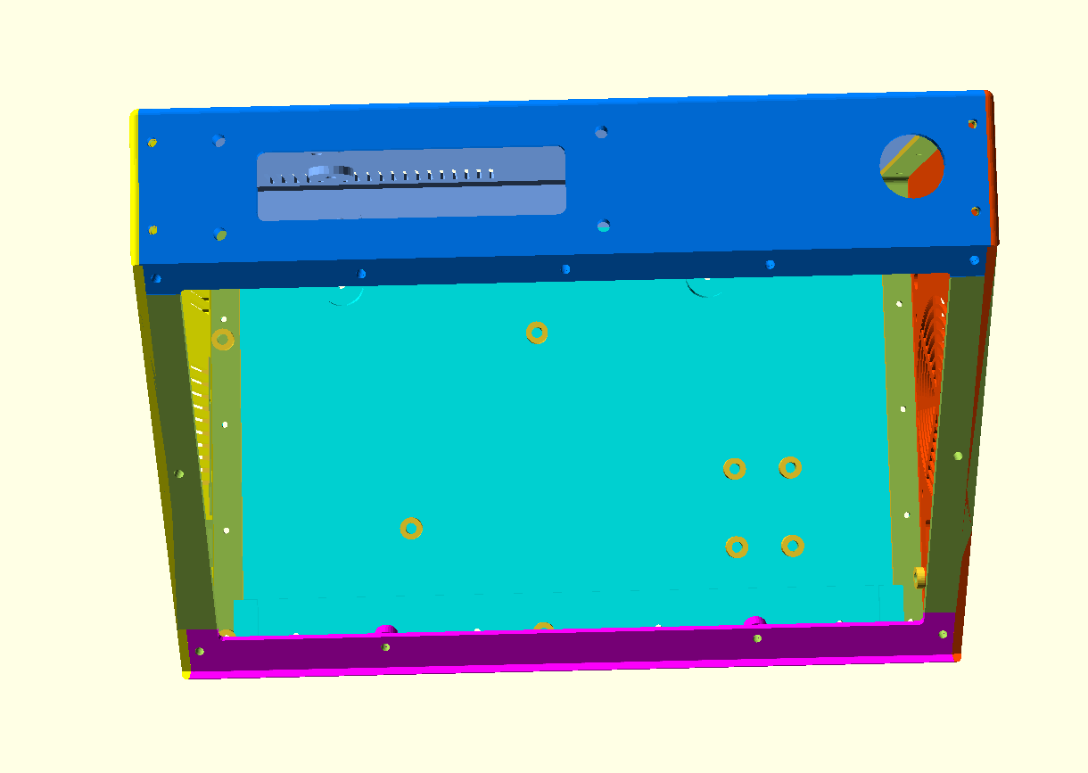
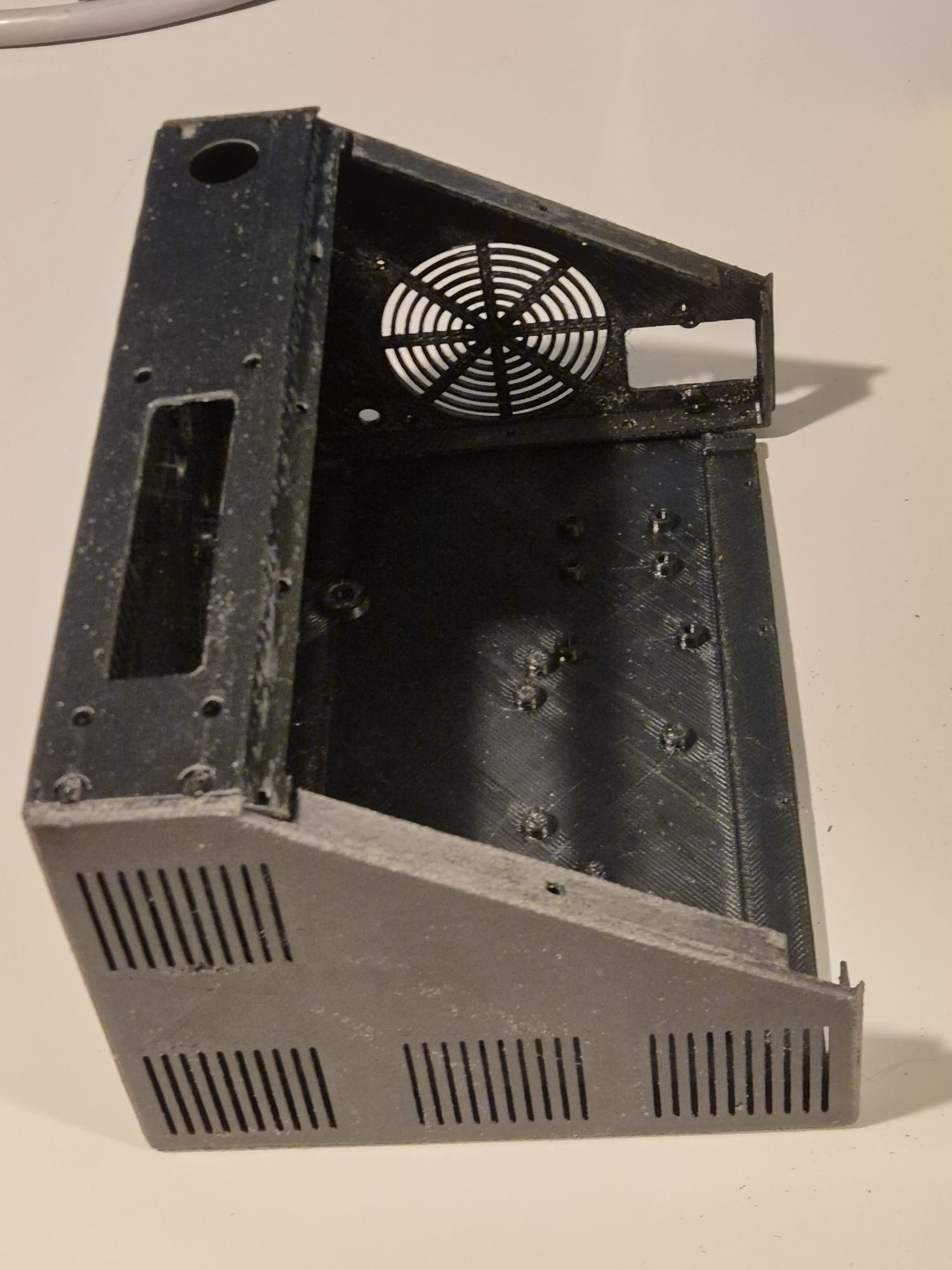
The CNC box design is available in 6 separate design STL parts that interlock very well and will have to be glued and (if you so desire-screwed) together.
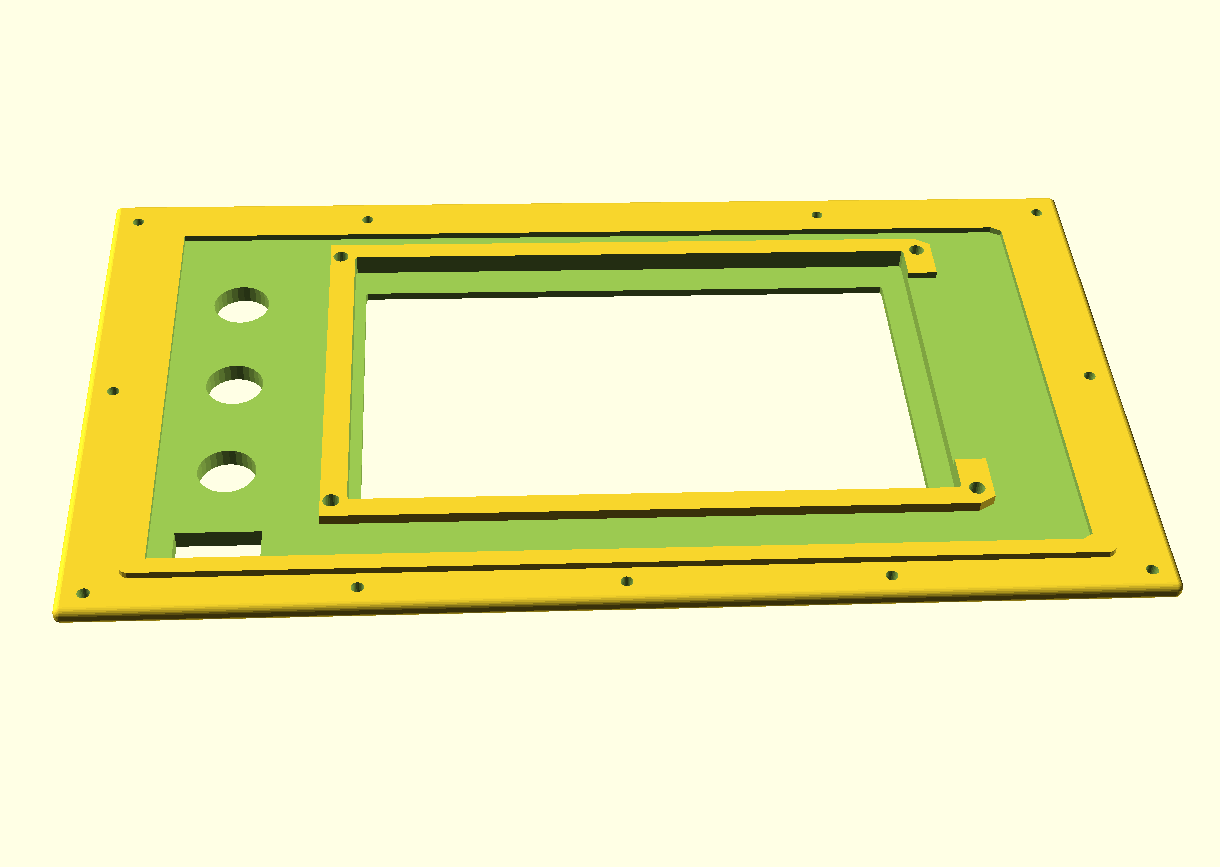
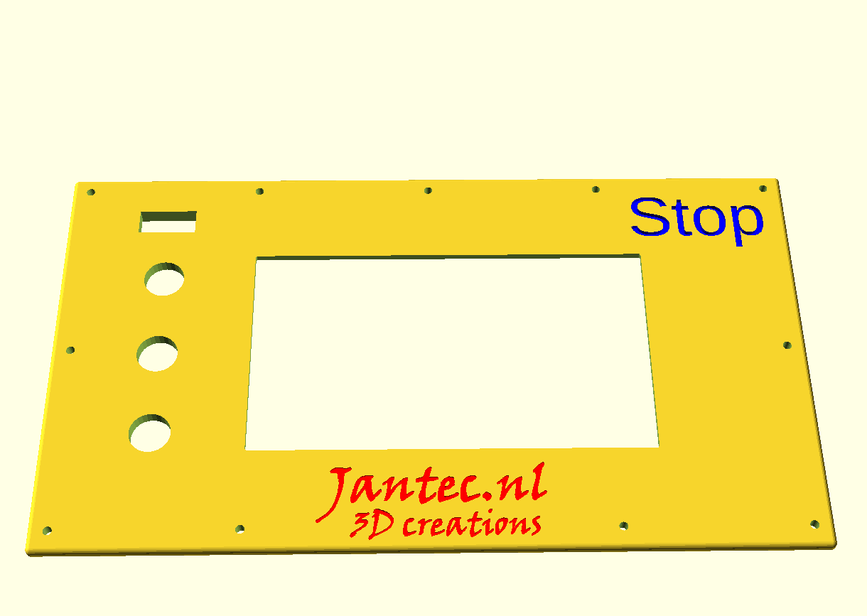
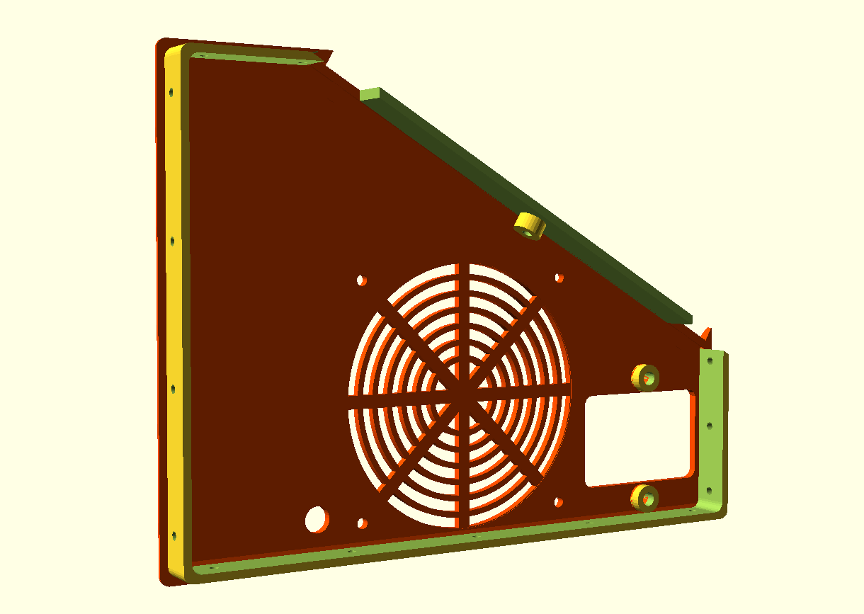
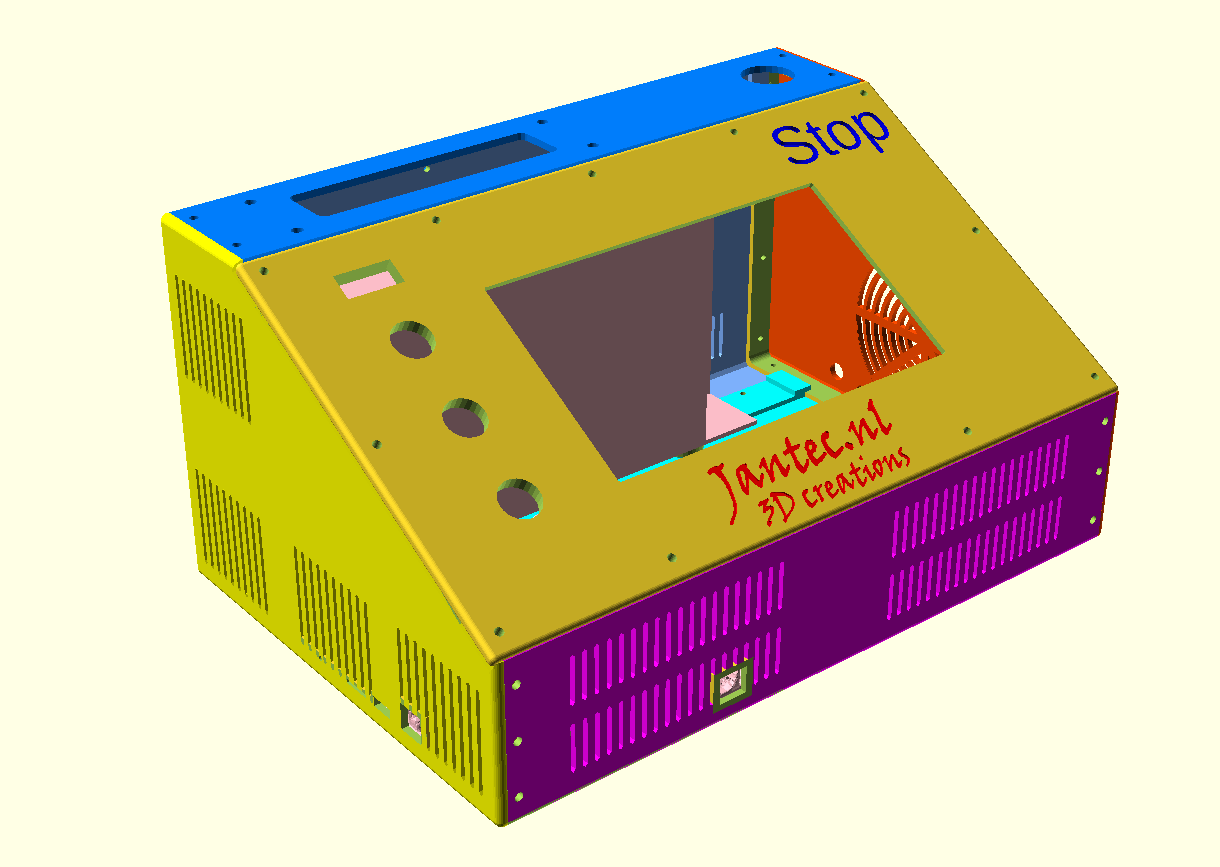
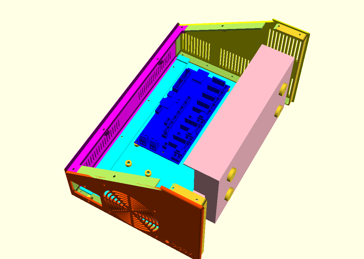
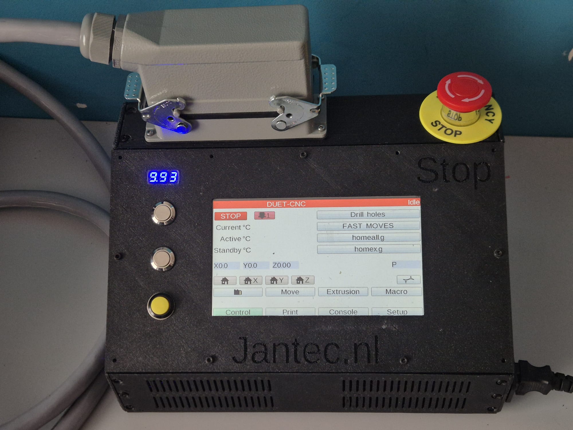
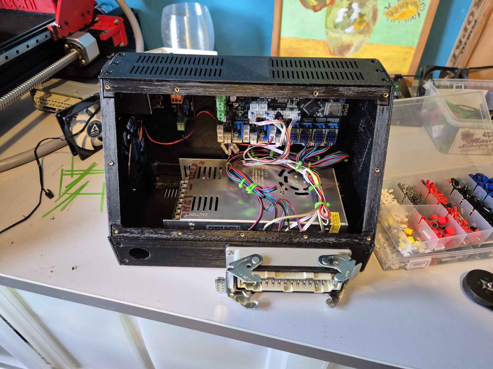
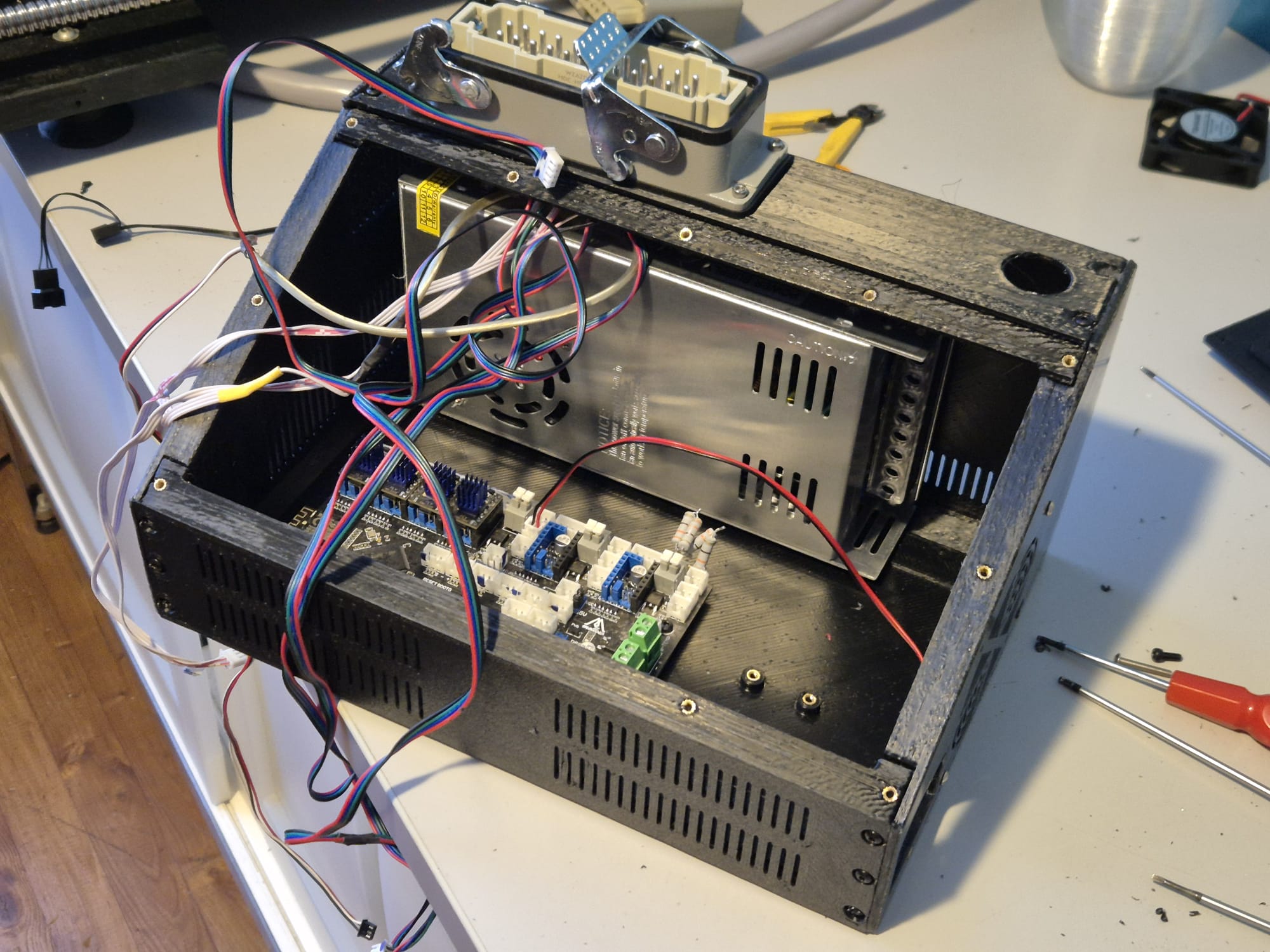
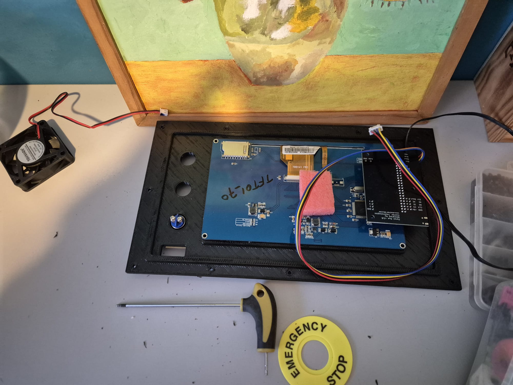
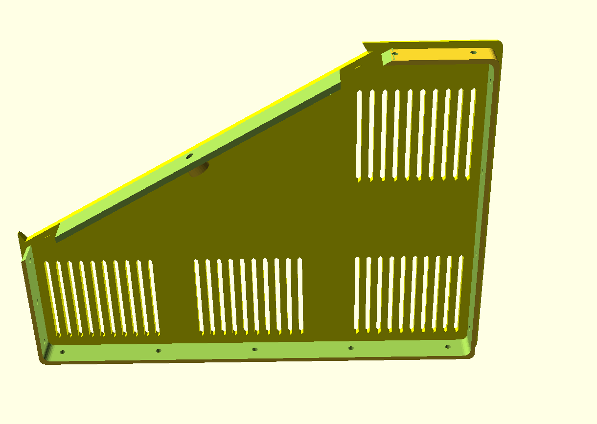
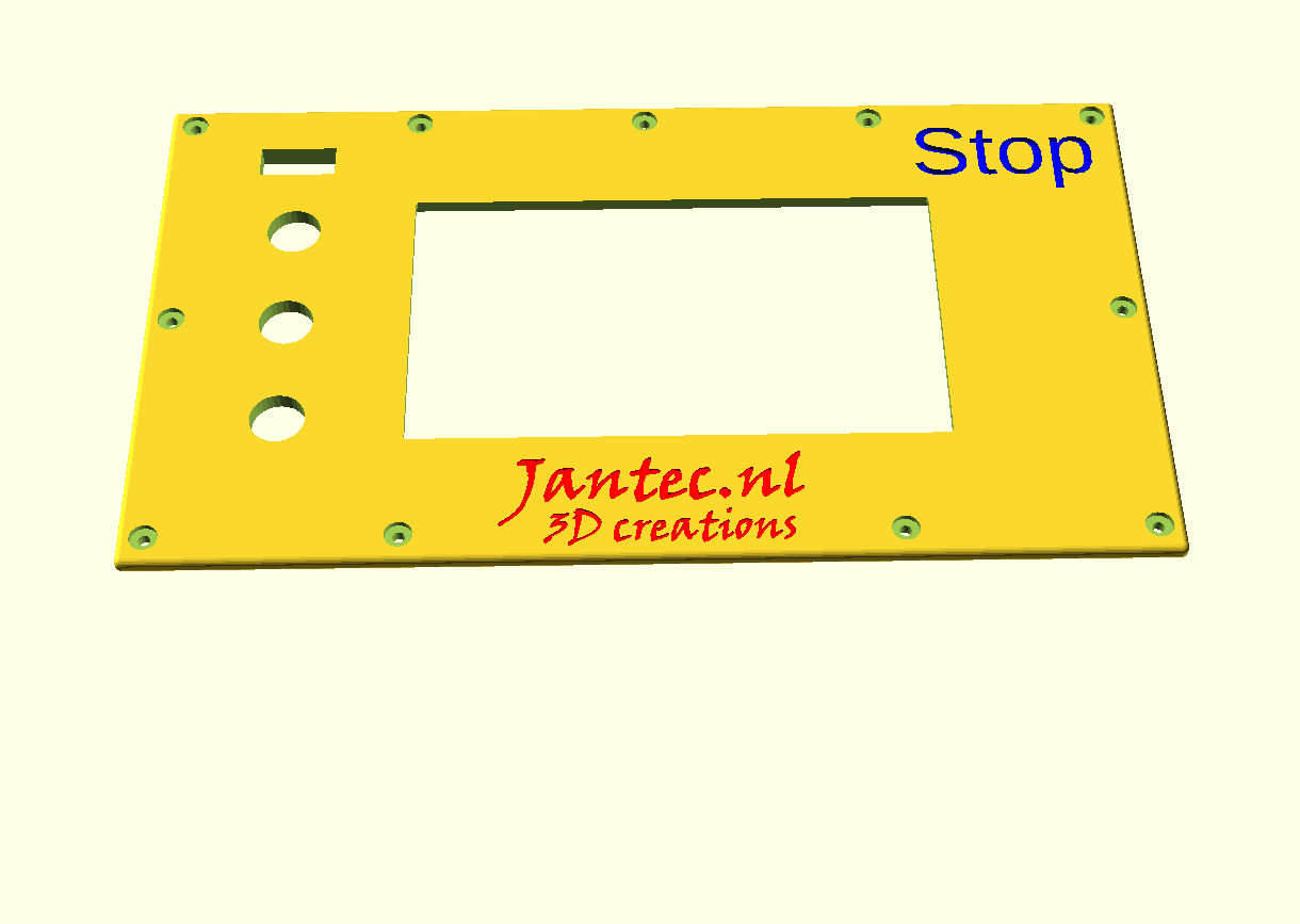
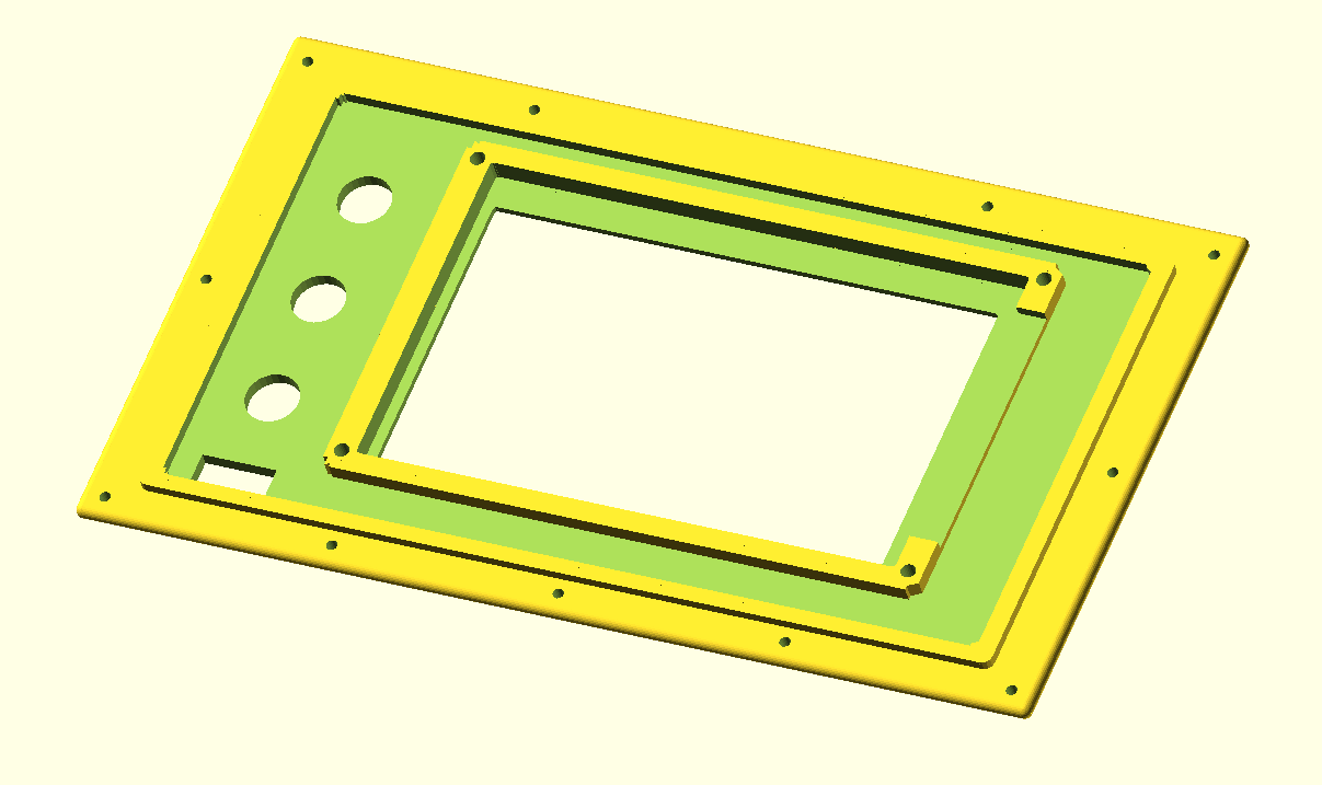
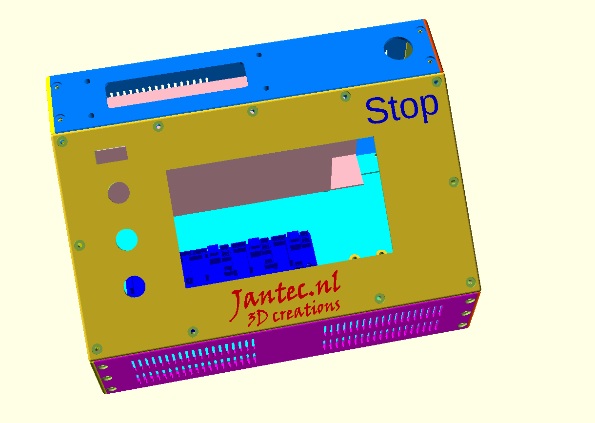
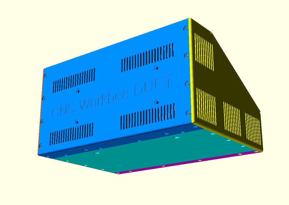
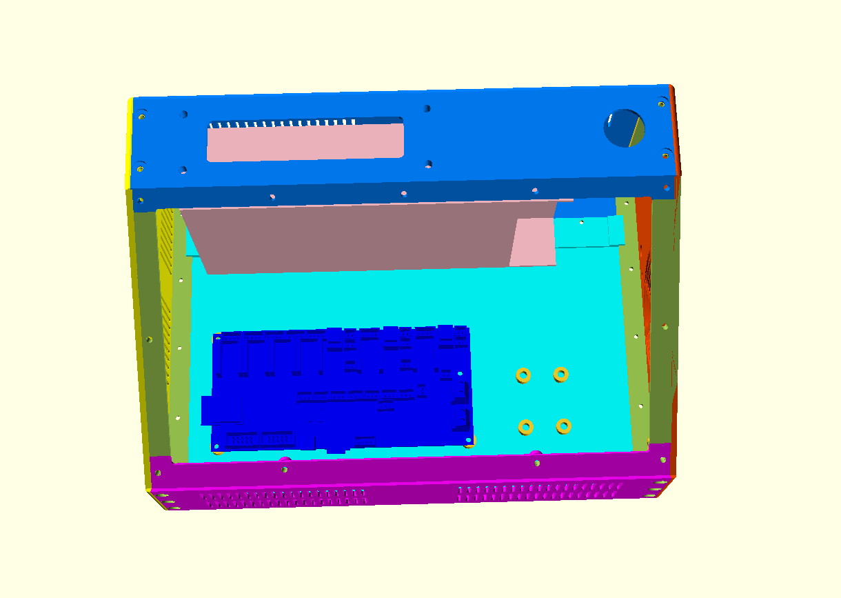
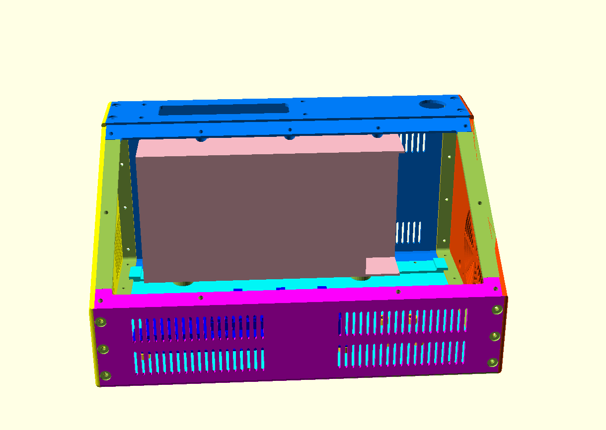
The tilted top panel houses a FysetC Duepanel 7 inch LCD module that interconnects to the FlyCDY2 or 3 ( and will also fit to the Duet3, obviously).
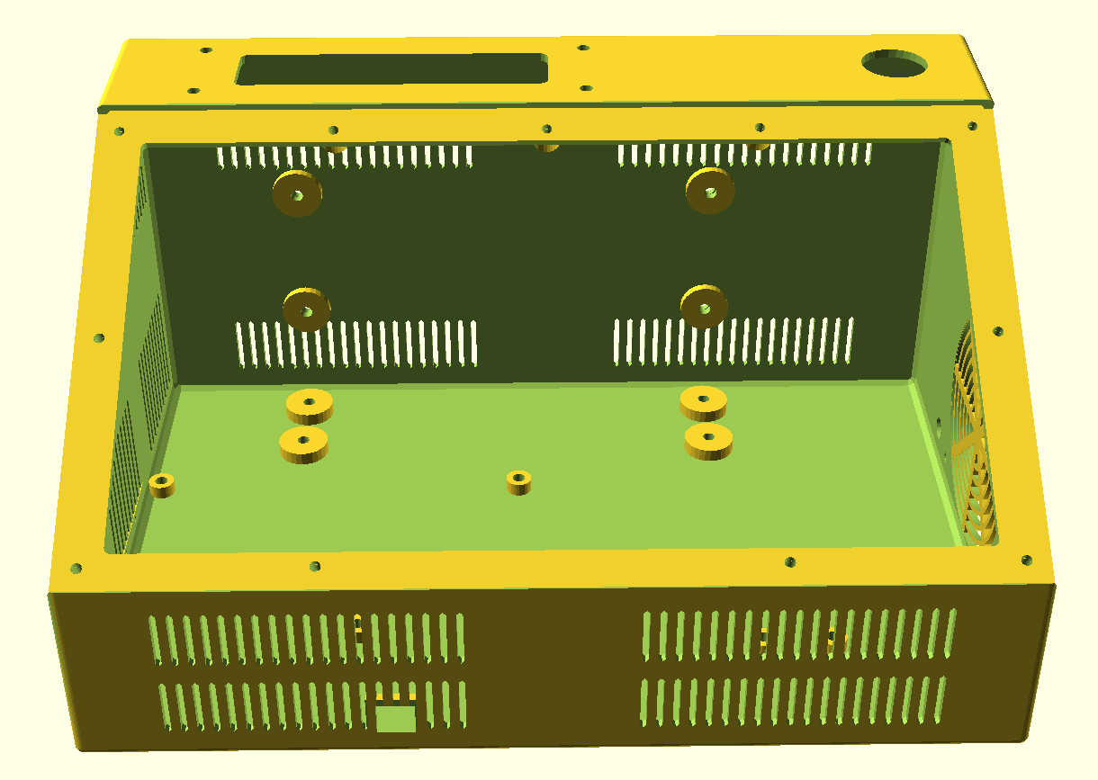
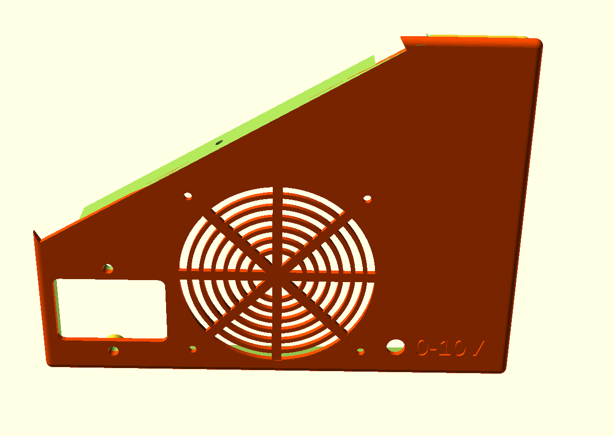
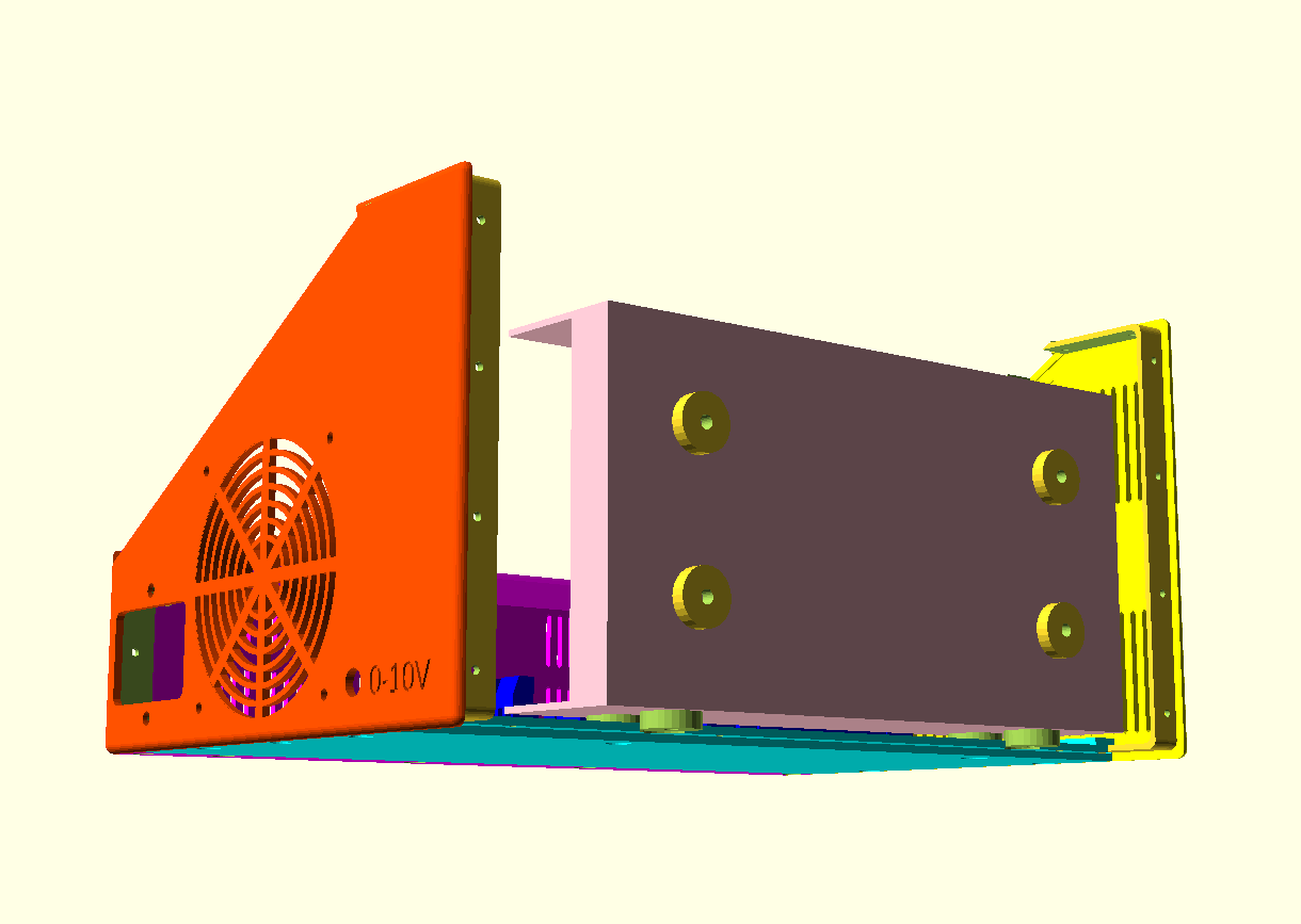
The box and panel also include holes for a 24-pins multiconnector on top, a panic button on top, an 80mm fan unit, a filtered power inlet unit (in my case, for 230V Europe standard) and 3 button holes on the tilted panel, as well as a small hole for a voltage reading unit. Any other required holes can best be done after printing. Just with normal tools, by using painters tape first to cause minimal collateral damage to the case.
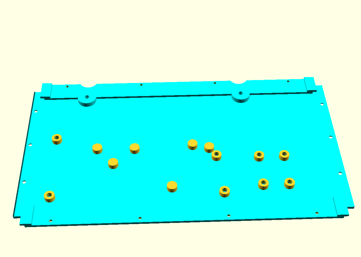
All parts that can be screwed on or-in, can utilize M3 threaded inserts at the mounting points inside. The holes are supporting these. This is not done for thePSU (obviously, the M4 mounting bolts run through the case). The fan is mounted with M3 bolts from the outside through the case and secured with nuts against the fan’s body.
I always print tools and toolcases in ABS at 260-270 degrees, 100% fan and 100% infill. . Use minimal support of about 85% for these parts but always use maximal adhesion on the OUTSIDE only!
Also, set Cura to a shrinkage correction of 100.7%, due to ABS black shrinkage of 2.2 mm on the long side of the box. (The xSize should be 295 and this was measured 292.9 after being printed as full box)
For constructing the box from 4 individually printed parts, first connect the bottom parts without glue. Then, attach both the sides and screw in the front panel. Then, where needed file or sand off ledges so it all fits properly. Then, remount it all and let the glue find its way between the connecting overlapping ledges that connect the parts.
Print all parts with the vent openings down.
All parts will print best with support 85% AND adhesion outside only ON.
Print support with 85% angle support everywhere at 5%, so the M3threaded bus-supports will be printed well.
PRINT ORIENTATION EXAMPLE (Cura, VORON 2.4-600)
Please be aware that the 6-part design is developed with printing in mind, so the horizontal printing orientation as shown above is the only way to avoid overhangs in the interlocking ledges. This also goes for individual printing of each part.
I print this with an 0.8 mm nozzle at 0.4-0.6 mm layer height and a full print-run of all items at once still takes 1 1/2 day, at 100mms speed.
Therefore, I am now printing each part individually so I can manage it a lot better. No fun when you run suddenly out of filament..-)
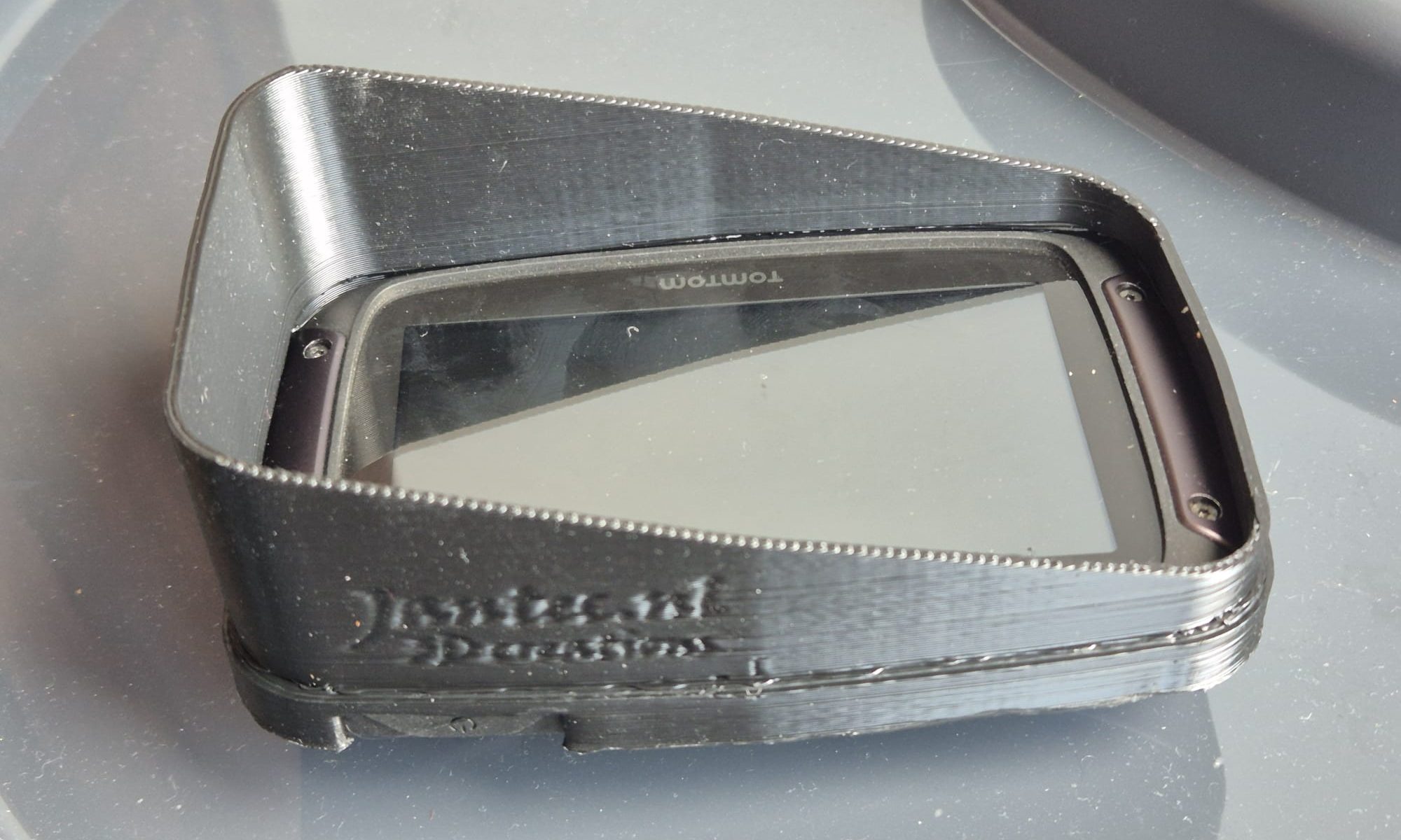
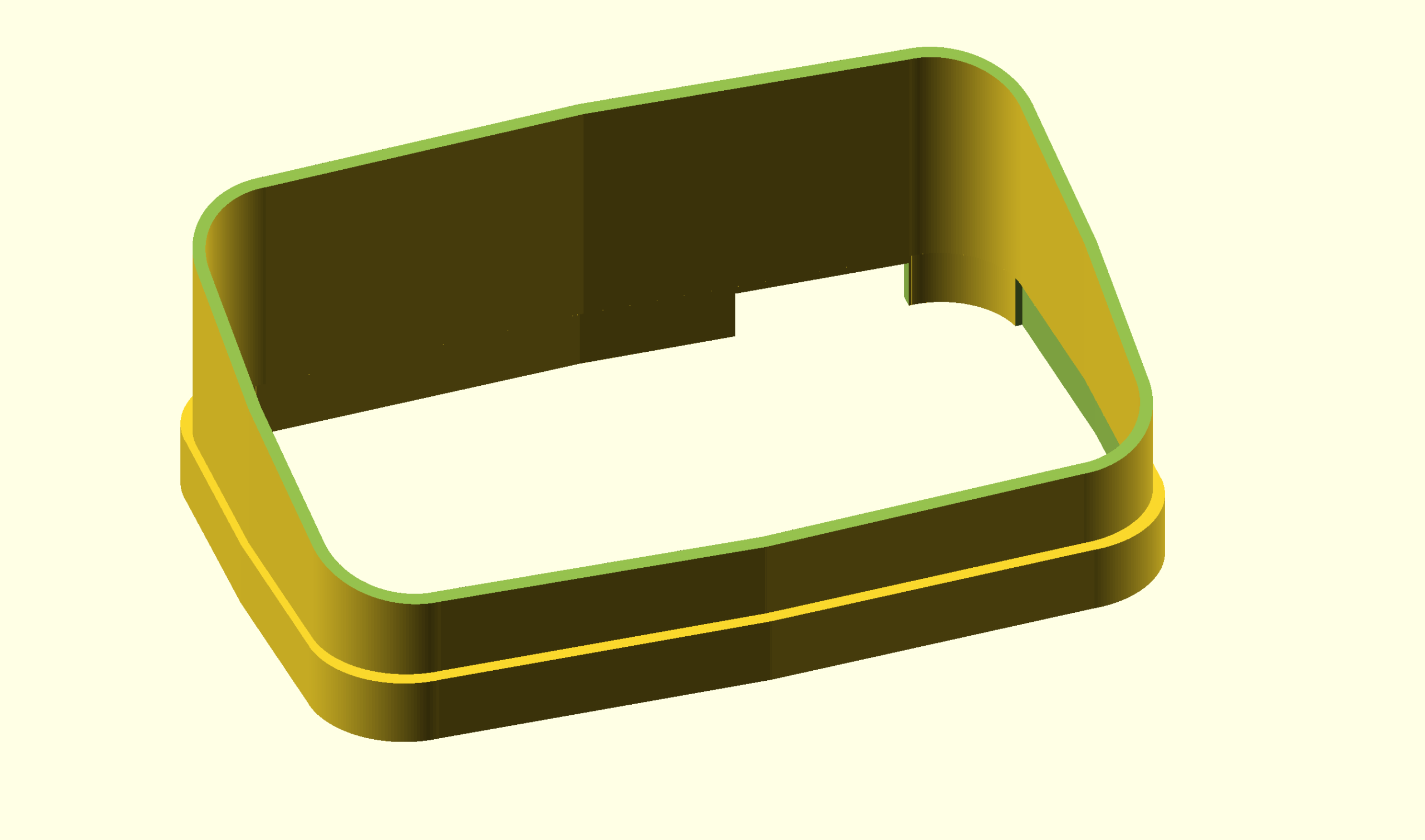
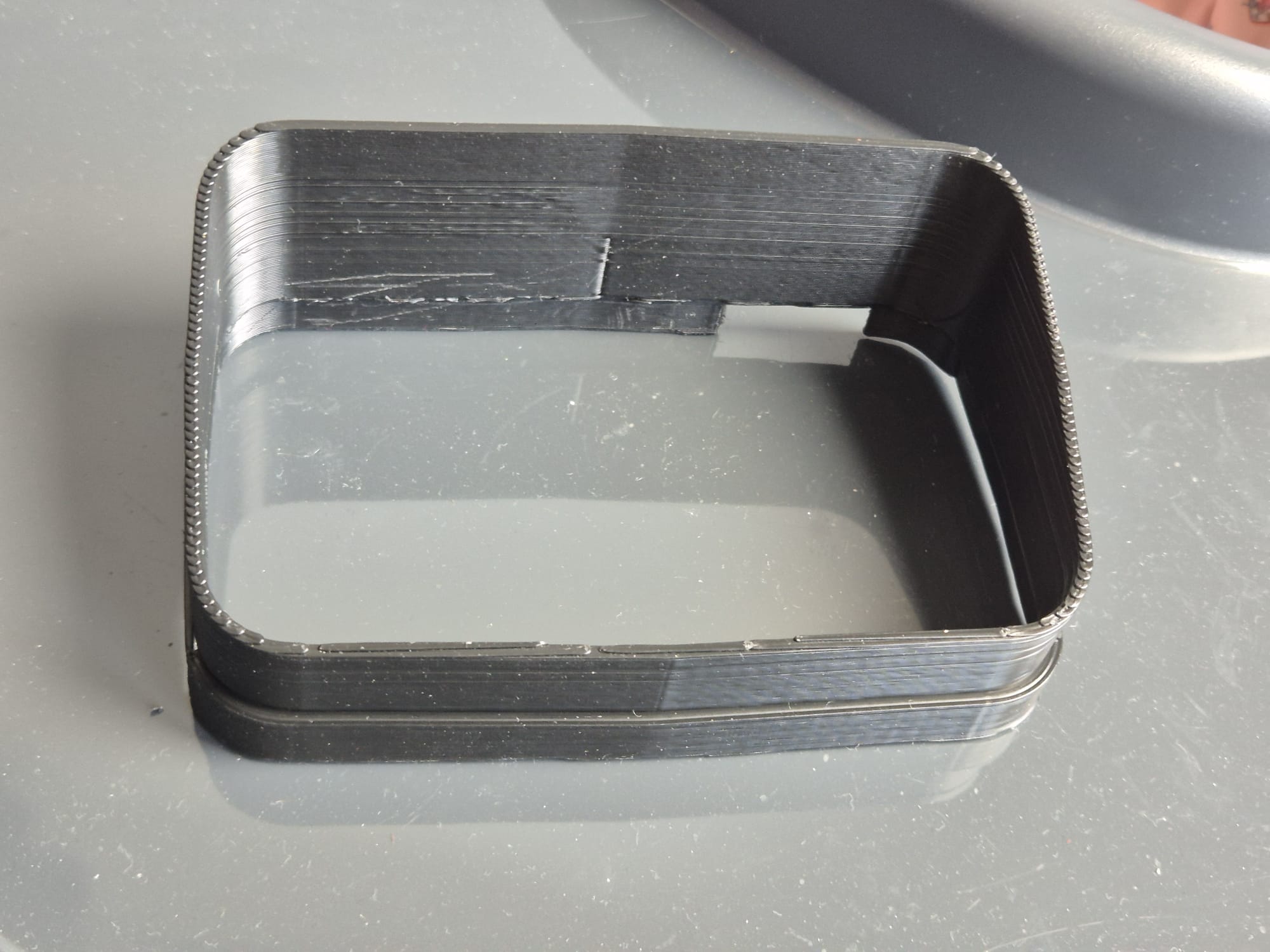
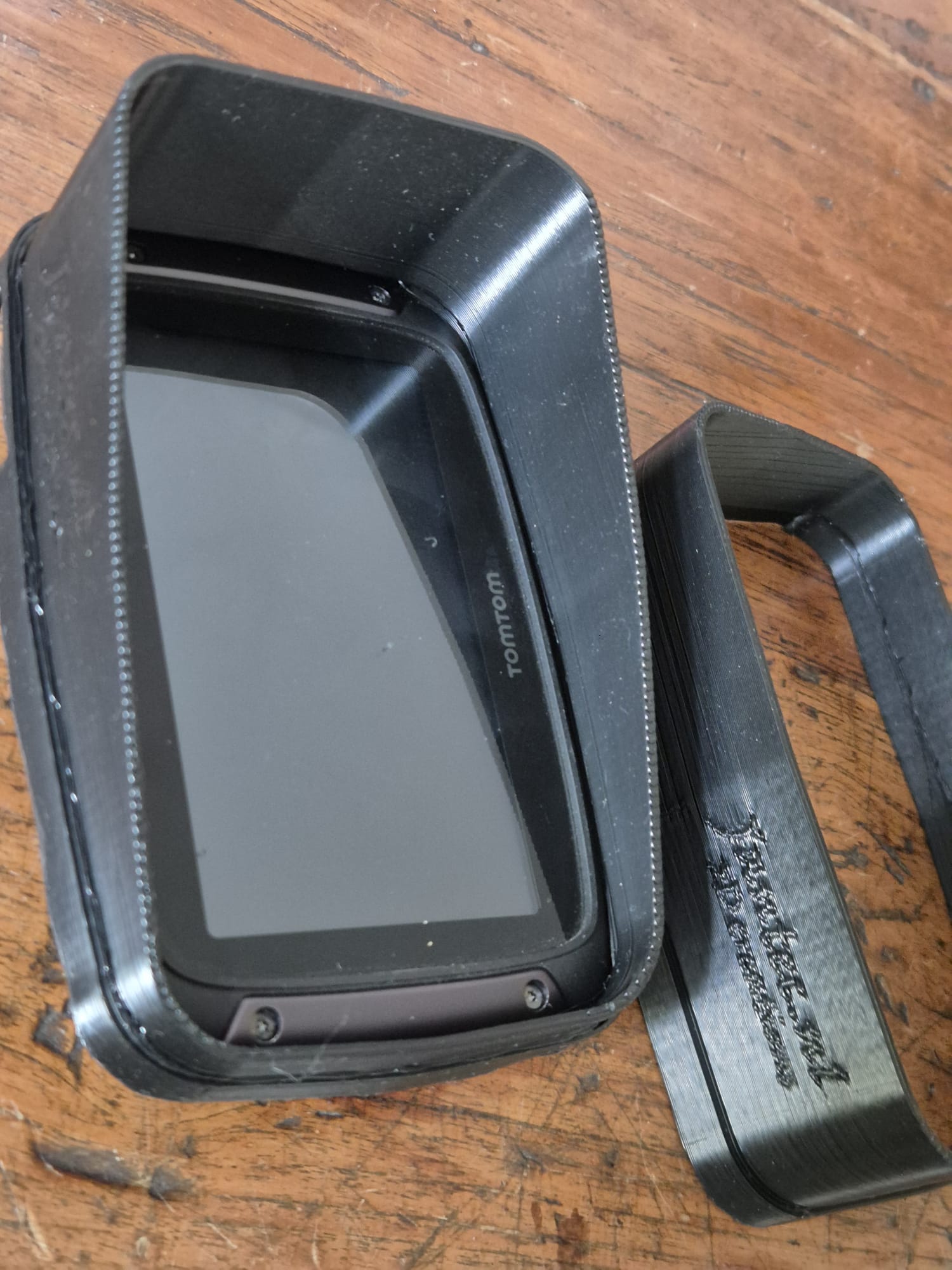
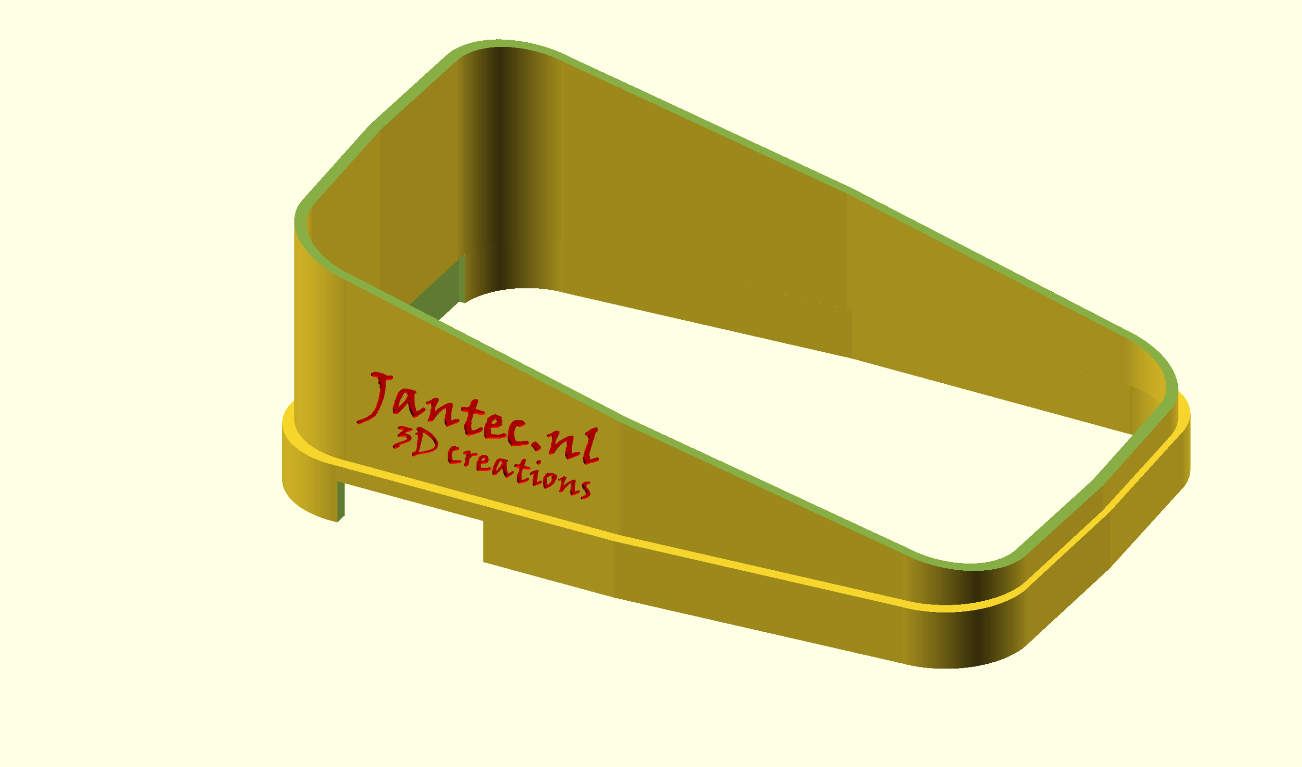
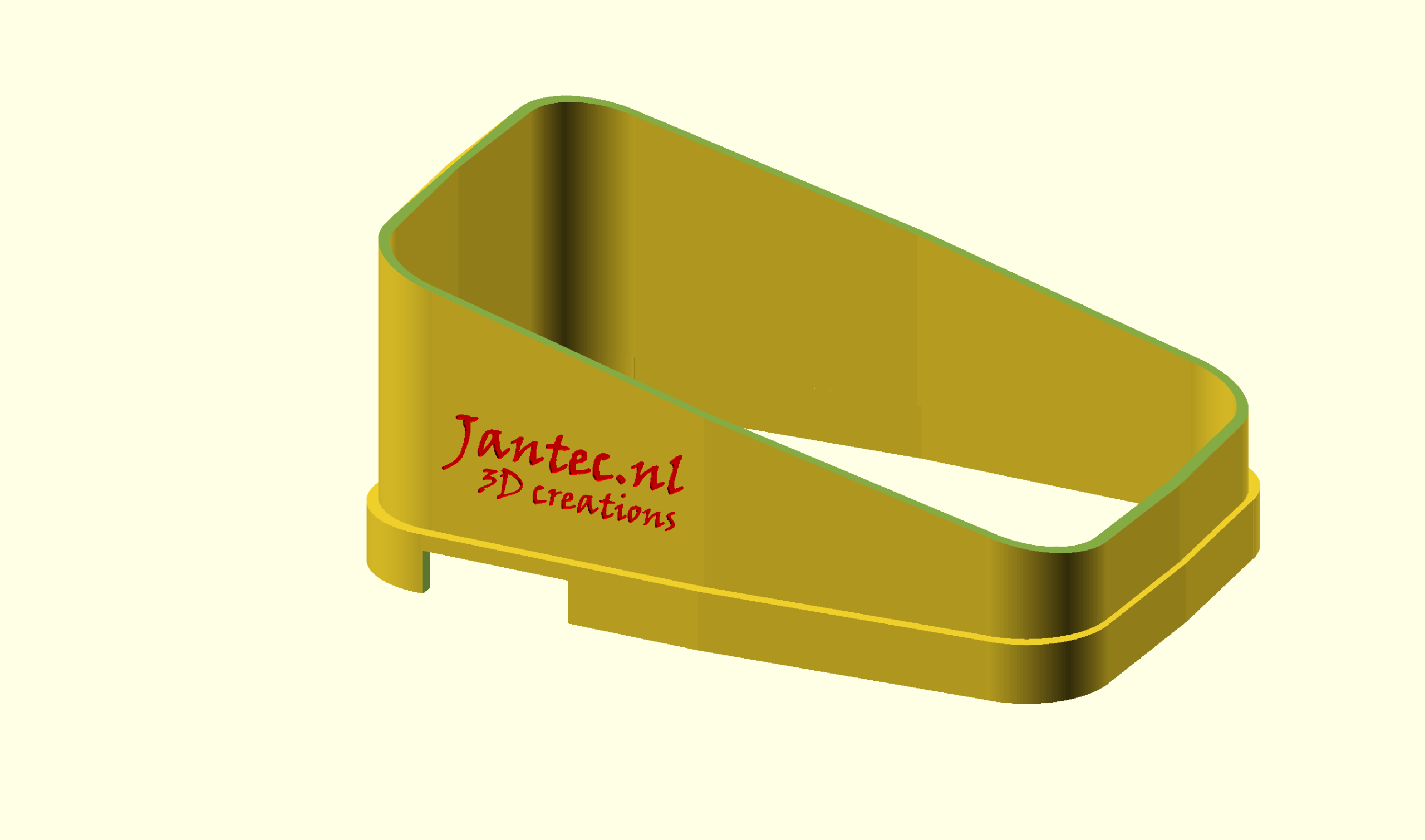
But I really needed a vertical one for usage on my motorbike.
So I changed the horizontal sun shade I had made earlier to a vertical one, which was very easy once I had the horizontal one really perfect. It took a couple of fitting trials before I had it good enough.
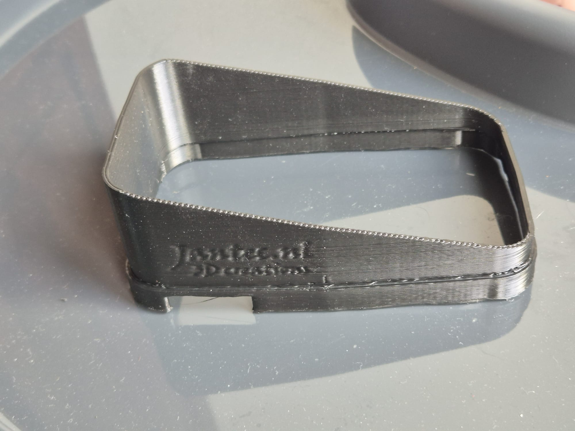
I printed this all on my hi-volume Voron600 with black ABS at 275 degrees, nozzle 0.8mm and layer height 0.4mm, 32 minutes to print the complete sun shade for my Tontom Rider 550. I always have the parts fan at 60% except 1st 3 layers and I print at 120mms, except 1st layer which is 20mms. Travel speed is 200 mms , rather low for this print at 0.4mmLH.
I use a rather high setting for Z-hop height at layer changes because this particulat ABS filament at this temp can give a small blob at the end of print lines and I don’t want the nozzle to jam into this at layer changes. Nor do I want to retract any more than 0.2mm since I don’t want any filament to get stuck in my so-called cold-end.
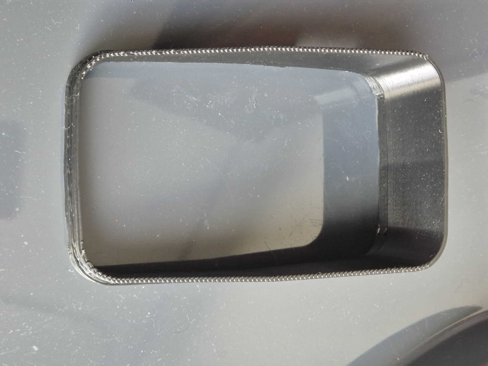
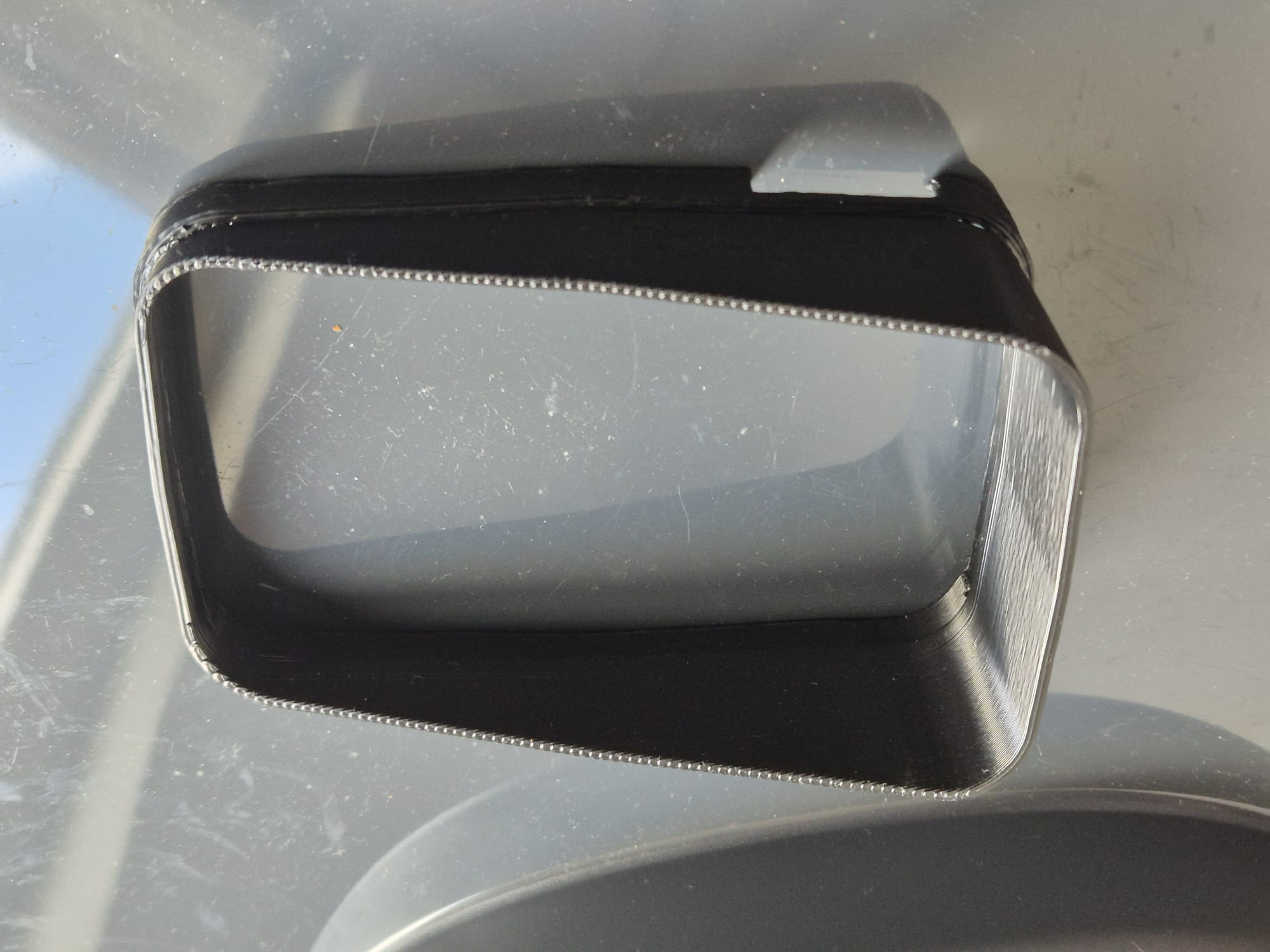
The sun shade fits snug around the Rider 550 but if you feel it is not tight enough, then print the sun shade at 99 % for the X and Y multiplier factors in your slicer.
And- yes, you should be able to print this STL file on any 3d printer with any filament and use your own preferred printer settings.
You will get much nicer prints when you use a 0.4 nozzle in your hotend and set it at 0.2mm layer height. It will then take around 2 hours + to print. Cheers!
Object fan: 25% max from 5th layer, below this: 0%
MY USAGE OF ABS
I use almost only ABS for my professional prints with an 0.6 or 0.8 nozzle.
That is because it is cheap, makes very sturdy prints and it can withstand pretty high temperatures.
I use ABS mainly for car’s interior parts, garden goodies and so on.
For any stuff that gets in cantact with food, kids and so on I use PETG.
For any other prints and all multicolor prints I use PLA.
Since I use dedicated printers per type of filament, I hardly ever have clogs or ruïned prints.
ABS- my story
Actually, there is not one standard for ABS settings. That’;s due to the fact that not all ABS on the market is really the same type.
However, I can give you some hints for different types of ABS 1.75 mm filament, after my extensive experience with those specific types of filament.
DO PRINT MY TESTPIECE PRIOR TO PRINTING ANY OBJECT and inspect the brim, and the sturdiness of the wall adhering, and the layer adhering.
Regular ABS: nozzle temp 270 deg C (15 deg too low), bed 120 deg C, object fan 30% (should be 0%) , 0.8 nozzle at 0.4 mm Layer Height, printing speed set to 120mm/s, BIG BRIM everywhere, brim also at LH 0.4mm, line width set at 0.8 exactly, sliced all in Cura
If the print comes apart if you try to break it at low force like in the above picture, the print temp is too low. Same for the wings of the testpiece as for layer adherence.
If you observe a bubbly surface, your ABS is wet. It will probably not be able to save it. You can try to dry it in an oven or in a food dehydrator at 80 degrees C, for at least 10 hours. My experience is that this is a waste of time and energy. Just throw it away in the plastics recycle bin.
GENERIC ABS PREREQUISITES
For all ABS, you need a hotbed at at least 90 degrees C but 120 deg C is better;
You will also need a hotbed plate with either a layer of smooth PEI on it, OR a hotbed plate with textured PEI, which I use especially for my 0.8 mm nozzle prints.;
In general, never ever use a toolfan.Unless you are using low-temperature ABS like EASY ABS with the rquired lower bed- and nozzle temperature settings;
Always use a completely covering enclosure for your printer;
Always do a bed mesh that really works prior to printing ABS and make sure this is done at operating temperatures of both bed and nozzle;
Print with a really big brim everywhere, at least 10 lines wide, also for your support structure;
Print the first layer with at least your regular print temp, NEVER any lower;
NO object fan on first 4 layers!
SUNLU ABS (WHITE AND BLACK)
Sunlu has ABS filament that is shiny on the spool, and can be printed shiny at the right temperature. This filament is not very prone to warping.
Nozzle: 265 deg C
Bed: 120 deg C
Object fan: 30% max=regular, no object fan on first 4 layers
EASY ABS (RED)
This ABS is also shiny, makes very sturdy prints and needs lower temp than general ABS. And- it requires a bit of object fan speed. The prints come out shiny. This type of ABS is not at all prone to warping, as far as I experienced.
Nozzle: 235 deg C
Bed: 90 deg C
Object fan: 60% max=regular, no object fan on first 4 layers
GENERIC ABS (RED, matte)
This is the most difficult to print matte red ABS(on the spool) and requires very high printtemp, and can’t handle any percentage of object fan. The prints come out matte when printed under 270 degrees and at 285 deg they are shiny. This type of ABS is very much prone to warping. This is likely a type of ABS without any additions to it.
Nozzle: 285 deg C
Bed: 120 deg C
Object fan: 0% max=regular, no object fan on first 4 layers
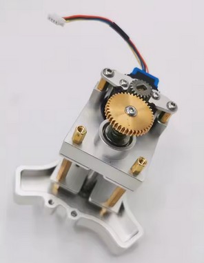
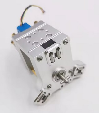
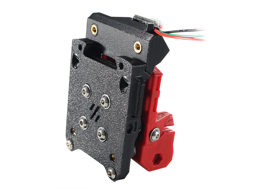
The system whereby the E3D tool changer determines the Z value of the four tools is fixed in the preset system files. This means that you perform a Z homing paper test for each tool to determine the deviation of each tool relative to T0, which is the leftmost tool. You enter the result in the config file as the Z-value for each tool, whereby I usually use “0” for T0 and the general Z-probe value, which I determine as the difference between the manual probe on the carriage and the nozzle height of T0.
First, you need to determine the Z deviation of T0 relative to the Z value of the carriage that picks up the tools. This is done by homing the bare carriage with a Z probe switch under the carriage to Z value = 0 on the bed.
Then you do a tool pickup from T0 and measure the height of T0 as the Z value. You then enter that value as the probe value in your config file. I find all this rather cumbersome, especially because everything changes when you change a nozzle, for example.
Below video: E3D toolchanger homing the carriage and do the tool pickup
DESIRED SITUATION
Ideally, I would prefer to have each of the four tools, i.e. T0 to T3, home X, Y and Z every time a new object gets printed, and in this manner you can also just select any tool to do the bed mesh.
You then take those four Z values as the Z=0 value per tool, and you’re done. This works great with the Voron that I run with TAP Z-homing! It doesn’t matter what you do with your bed or your hot end, gantry, etc. It doesn’t matter because the nozzle is used as a mechanical Z-homing tip.
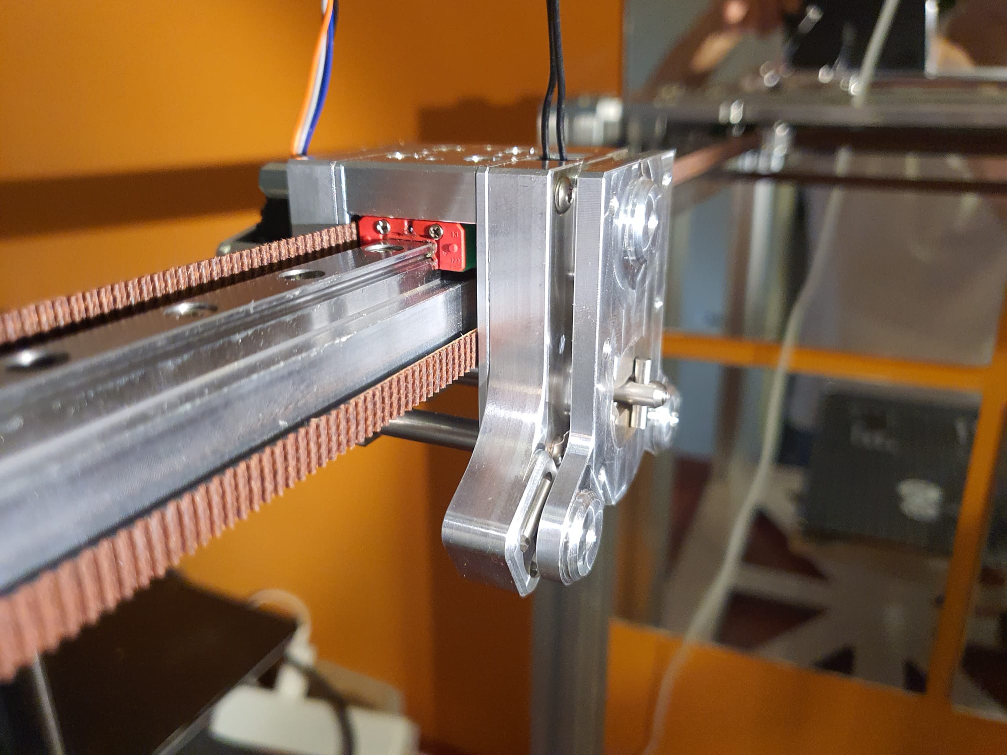
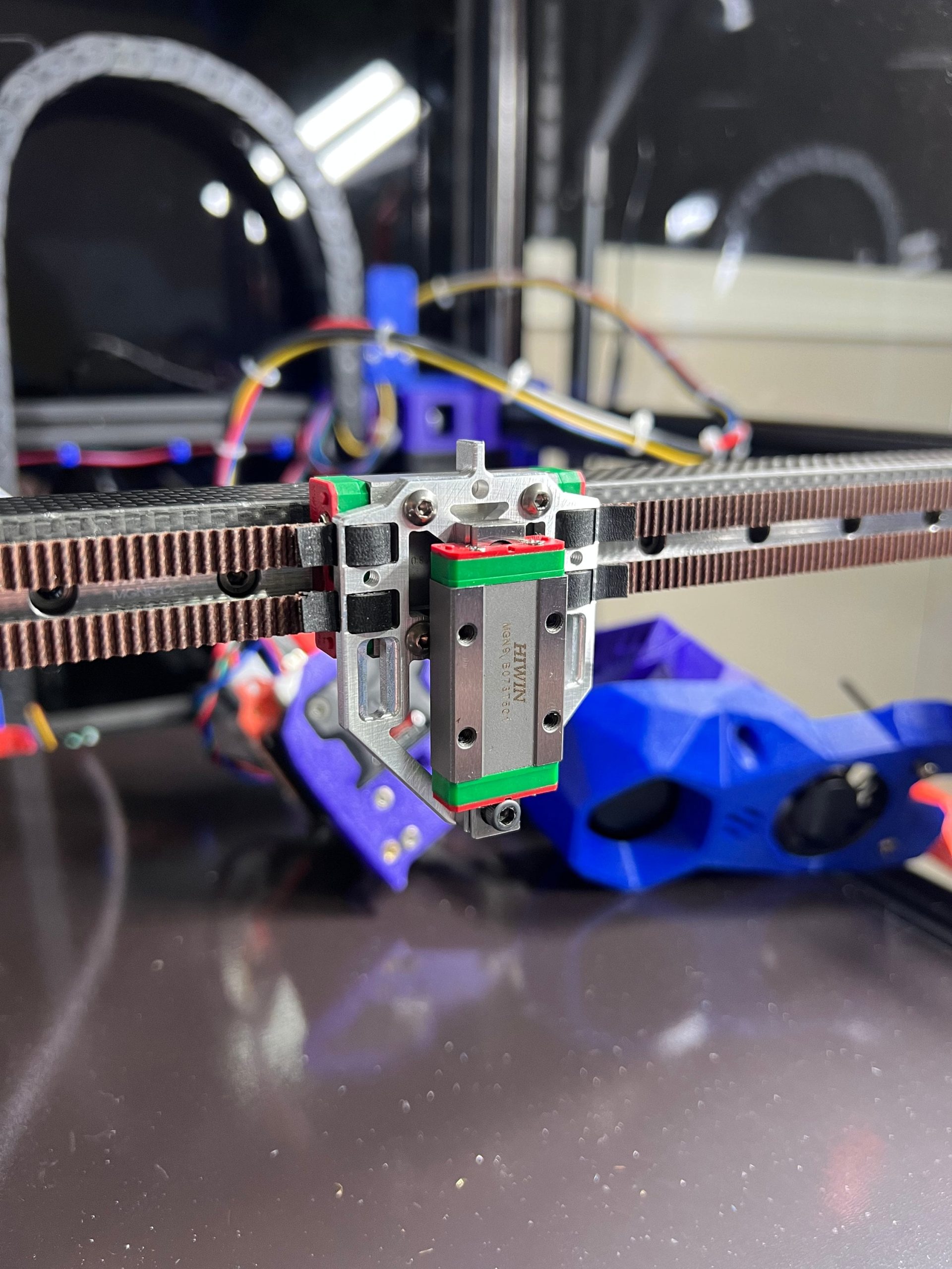
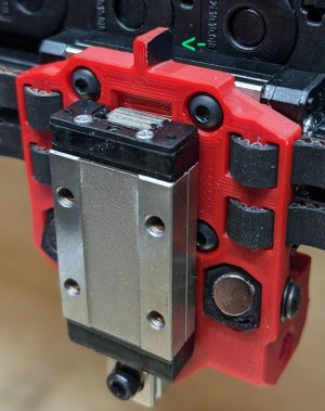
The tool pickup (the trolley) is very securely attached to the X-axis. The best solution would be to allow this entire unit to move vertically in order to enable the TAP function. That is still a challenge, partly because the A and B belts are attached to this trolley. This only seems possible with a new trolley to which the belts are attached and a separate tool changer pickup next to or in front of it. I then still need to create the TAP function between the two parts. And if the tool changer is placed in front, the X-axis must be moved back on the Y-axes. I’m not sure how that will fit….
After exploring all kinds of possibilities, this one remained: Keep the tool pickup in the same place and work with existing resources. Saw the mounting block on the X-axis slider into 3 parts and then mill 1 mm off the centre piece on both mounting sides. Adjust the side plates to which the belts are attached so that these plates can be reattached to the middle section of the slider block with new countersunk screws. The through bushings on the bottom no longer pass through the plate, and the plate must be milled away at the corners, just like on the top, to create approximately 5 mm of vertical play. Mount the two lower connection points of both side parts with two 1 mm spacer rings each so that the carriage can move up and down and the sides remain at the original distance from each other in order to maintain the stability of the moving construction. An additional mounting block for the vertical linear rail of the TAP slider is placed on the centre mounting block of the X-axis slider. Extension pieces are attached to the front and/or rear of the tool pickup, to which the TAP slider with the moving part is attached so that everything can move up and down by approx. 3-4 mm..
How the TAP function works on a Voron2.4 3D printer
ADDITIONAL: Self-searching tool changer
And while I’m at it: why not make a self-searching tool changer? Roughly set it up with the XYZ coordinates per tool, the last part electronically with a guide system between the pick-up trolley and the tool, and the final fitting with the existing mechanical fitting.
Instead of determining exactly where each tool should be picked up and put away by trial and error, you could use an electronic guidance system to aim precisely at the right tool when it needs to be changed. No more hassle with X-Y settings and homing axes. Because if anything changes as a result of mechanical stress in the frame or due to small deviations from the X and Y homing, picking up and putting away tools will regularly go wrong.
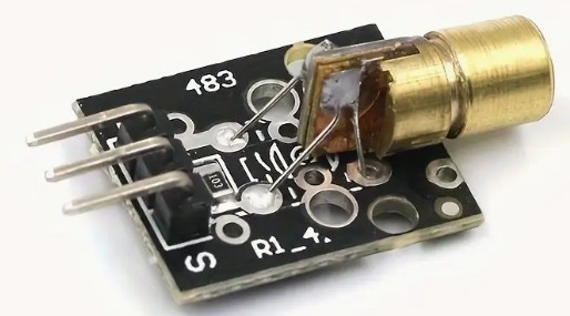
One possible way to do this could be a passage LED/LASER system, such as those used at shop entrances.
.
mini focussable laser module
mini laser receiver module
Or simply use infrared, which is invisible but also much less dangerous.
To do this, you use a targeting laser, such as in a levelling system, or an infrared laser with a receiver.
This is placed on top of the X-axis on the moving toolhead and is aimed at the tools, at a 90-degree angle to the X-axis.
You then activate the correct tool you want to move to or pick up as the receiver.
With an X-sweep movement, you can make contact with the receiving tool and then move in a straight line towards the tool until you reach the pick-up point, which is specified in absolute Y value in the configuration file. Sounds like a great development!
ADDITIONAL: Precise XYZ homing of the tools
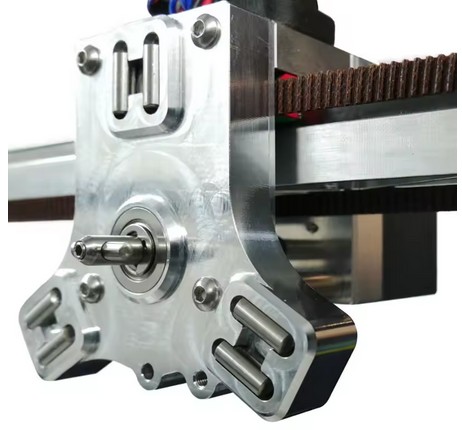
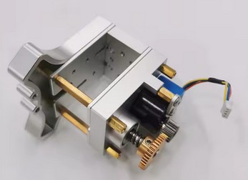
And I would like to have a way to centre X, Y and Z of each tool nozzle in detail relative to the other tool nozzles, just like with my CNC machines:
With such a head alignment block, you can accurately determine the position of all axes on a CNC machine. First, you need to determine the approximate position of this block, with an accuracy of approximately 1 mm on the X and Y axes.
The alignment block is electrically insulated and works by making contact between the tool tip and the block.
How does homing with an alignment block work?
You programme a centring macro in G-code.
First, you temporarily set the motor power to the lowest possible value to avoid damage if anything is in the way of the moves to be made.
Just as when I regularly do a home-all, with this new method you also set the bed and the relevant tool nozzle to operating mode (e.g. bed at 70 degrees and nozzle at 180 degrees).
Then you do a normal XY homing, which in my case works with limit switches (or optical switches) at the start of the X and Y axes.
A Z-homing action is also necessary unless you do not want to remove the Z-move block that occurs when you have not first homed Z.
Then move the Z-axis up sufficiently to avoid hitting the block.
Next, move to the absolute XY position of the block.
When you are above the block with your tool, home your Z.
Then home on Z+0.3 both -X and +X, and in the middle of -X and +X home -Y and +Y.
The result is the exact position of the centre on the flat Z plane of the alignment block.
Because you know exactly what the position is in relation to the bed centre and from X0, Y0 and Z0, you can translate this directly into the macro and enter the Z0, X0 and Y0 values as absolute values.
It should be possible to home the E3D tool changer tools in this way as well, with Z using the TAP function and X and Y using electrical detection as described above for the CNC milling machines. We will see if and how this will work as a supplement to TAP-Z homing with the current X and Y microswitch homing on the X and Y axes.
CONCLUSION -FOR NOW-
The credo still seems to be: If the E3D tool changer is working, it’s best to leave it alone. That doesn’t suit me at all, because I often move my printers around. And that doesn’t always go well.
So I’m going to look into these issues and, if possible, build something!
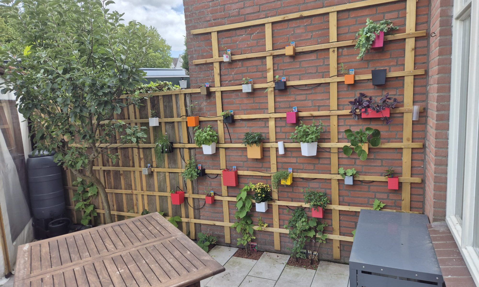
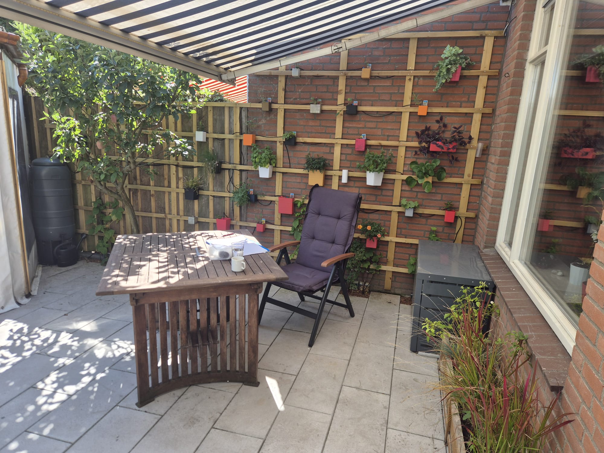
In my small garden, a wall from my neighbour’s house extension has always felt a sort of in my way. I thought a lot about making this wall a bit more visually attractive and I came up with this:
I created a setup with impregnated wooden garden planks, which I splitted lenghtwise with my small portable sawmill. The wood carries around 20 small 3d-printed flower pots in all sort of colors and shapes.
In the flower pots, I put in a variety of small plants plants of which most of them can withstand the Dutch winter time, so I don’t need to replace all plants next year.
Also, I put in an automated solar-powered watering system that utilises my rain water gathering supply bins.
I am very happy with the result!
Below in this post I have gathered my flower pot designs for this wall, if you click the images, the STL file will be automatically downloaded to your device.