Minimill CNC conversion Toolmania WMD16LV endstops

2021-10-30:  When converting (or upgrading, depends on your P.O.V.) a mill to CNC, it is absolutely necessary to have end stops on all ends. Except the low-end of the Z-axis, an end stop at the Z-axis low end is practically impossible.

On the Z-axis low end another solution has been established by using a Z-stop from the milling toolbit on a fixed X-Y position, OR by testing with the toolbit in place on the matrerial by sight or electronically.

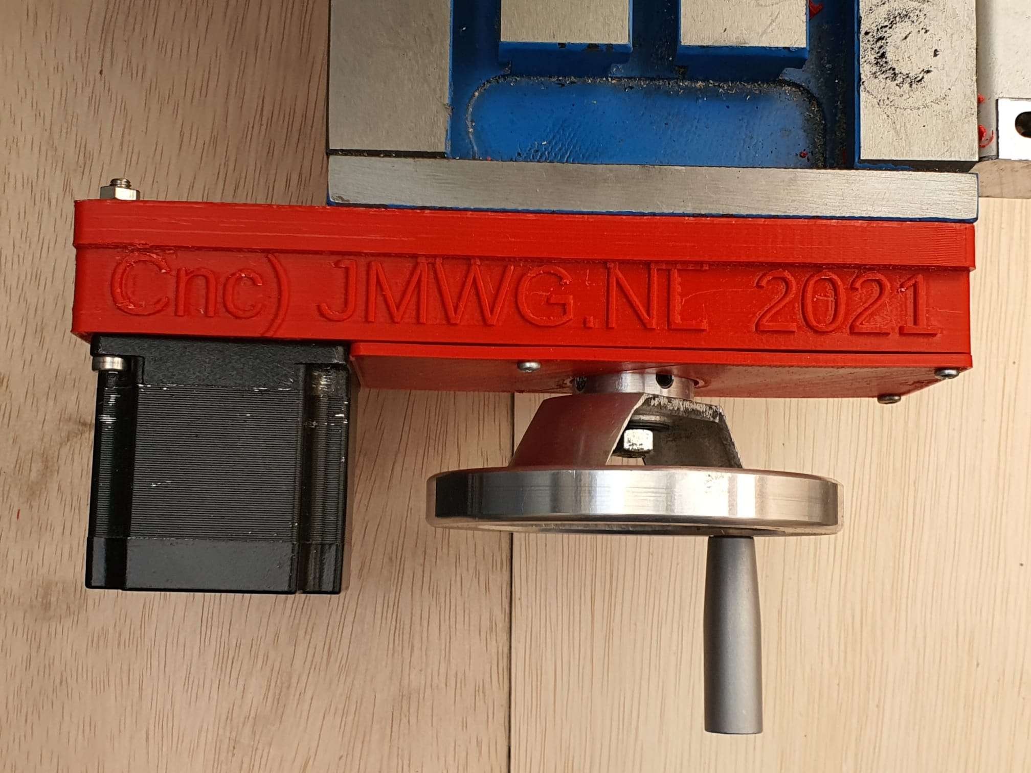
I bought a Z-position sensor for this, which is nothing more than an electrically insulated round pod with a flexible brass top. It is with one wire connected to the Mach3- motherboard as Z-probe and triggers when the tooltip touches the top of the Z pod’s brass top.  Therefore, this trigger is defined as ACTIVE when it is conected to Ground.  Since the mill will be grounded and thus also the tooltip is always connected to ground.  You MUST ground the mill, by the way.  Also for your safety.

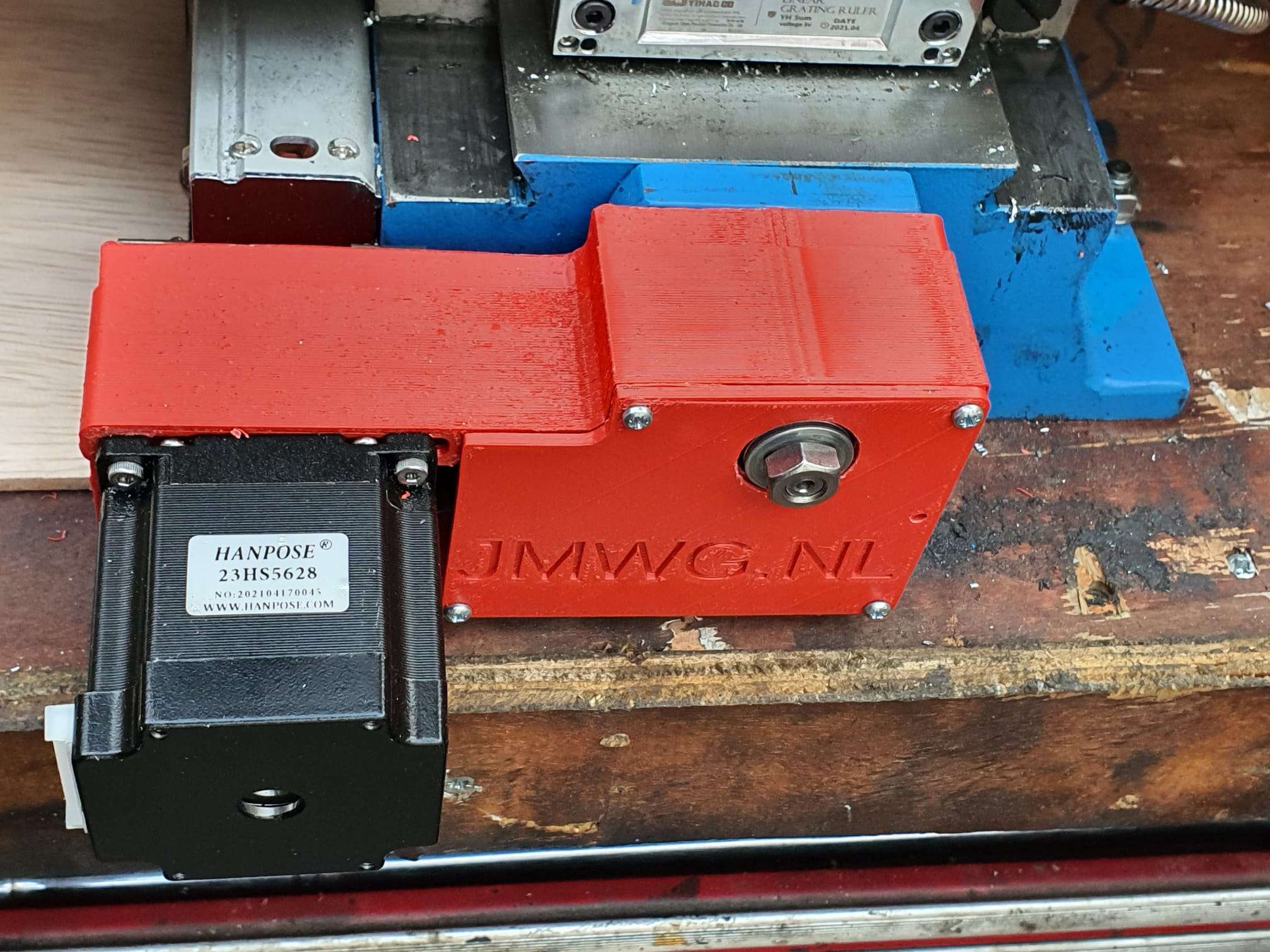
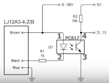
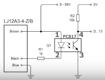
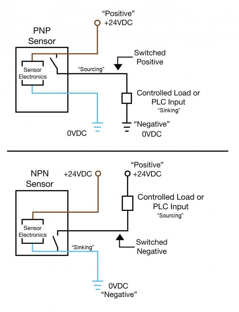
Leaves us with the 5 enstops for which I have bought the thinnest available inductive sensors. These are M6 size round and about 8 cm long. These sensors require power, ground and since they are NPN type sensors which means Normally OPEN when NOT active, they will  ground the output pin when activated at reaching the the stop position.  To activate these inductive sensors,  a carbon- containing metal would be best to use and bring the sensor close.  The trigger moment depends on the connected power voltage.  The higher the voltage, the more sensitive the sensor becomes.

I will use 12 Volts or 24 Volts, I will experience a bit with these settings.

NPN and PNP proximity sensors - OMCH

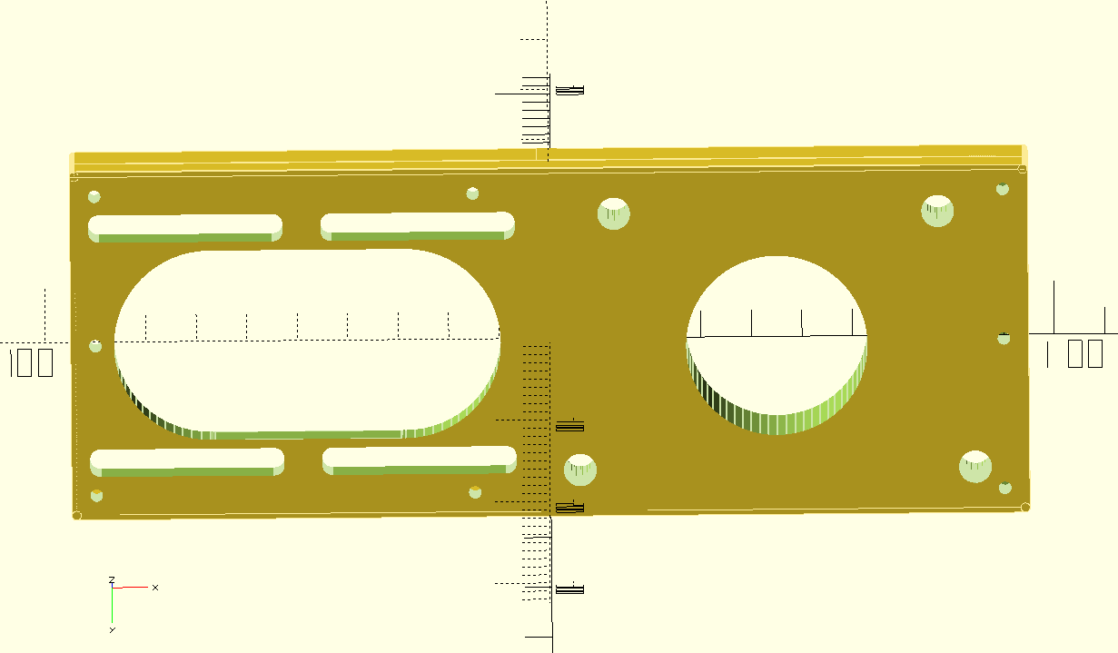
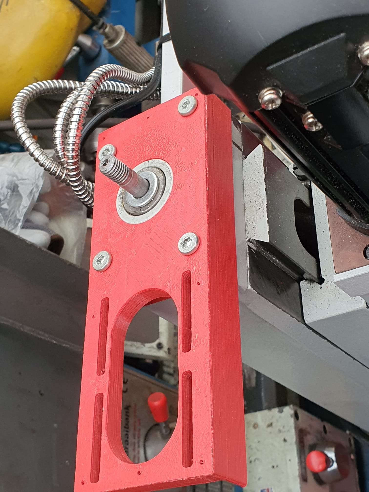
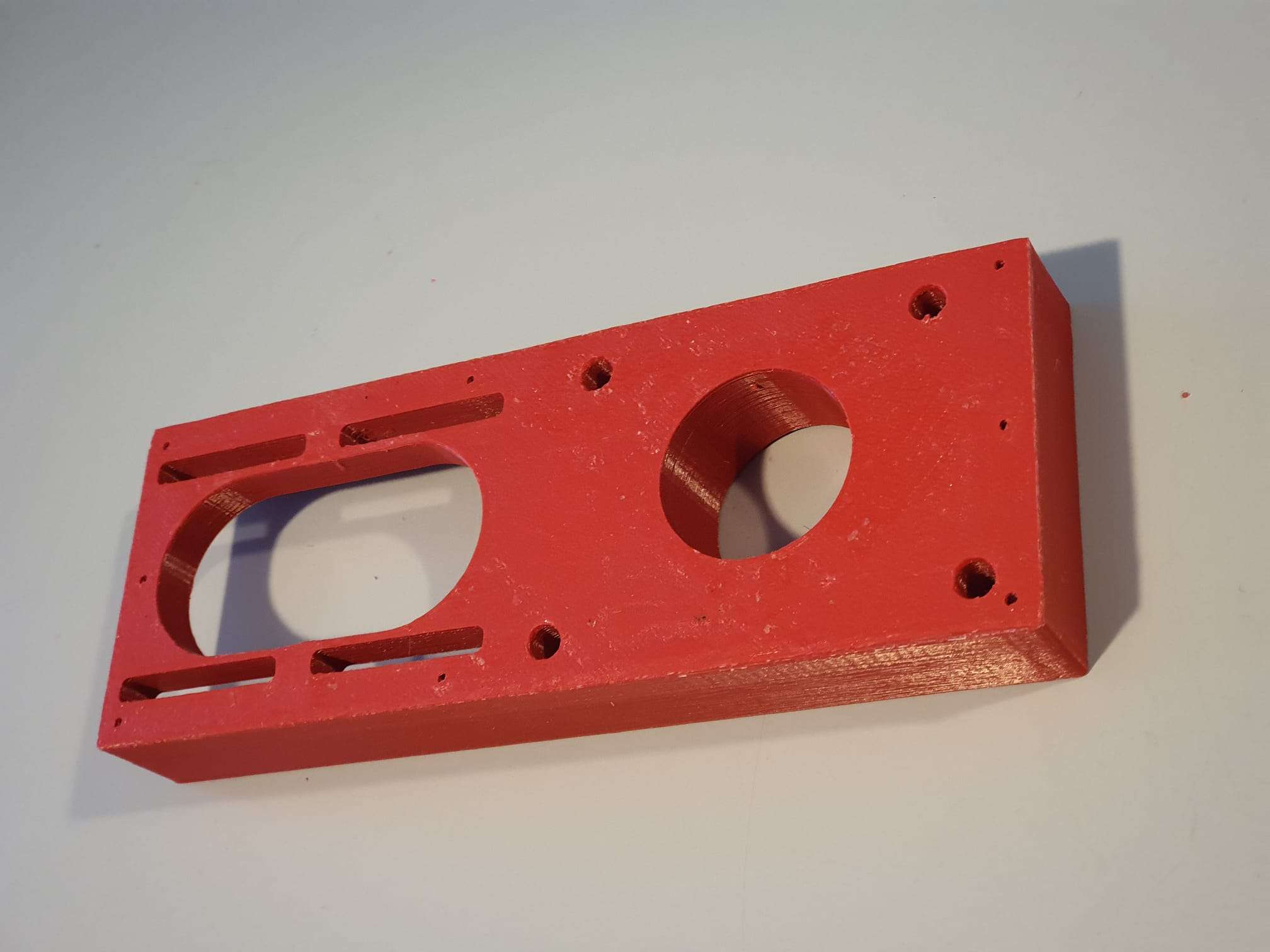
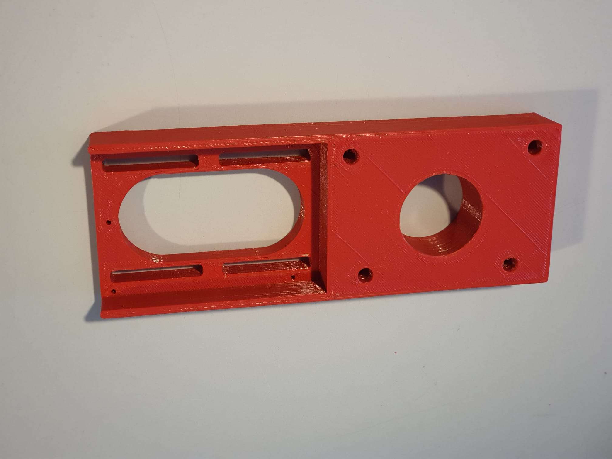
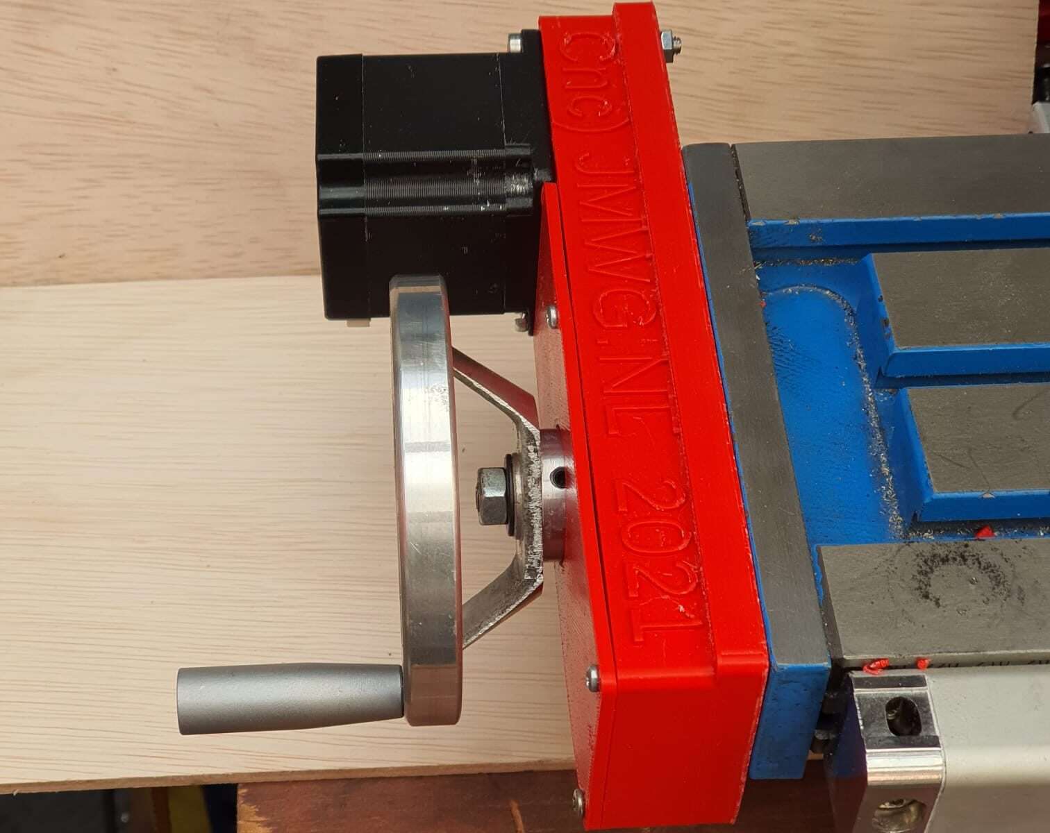
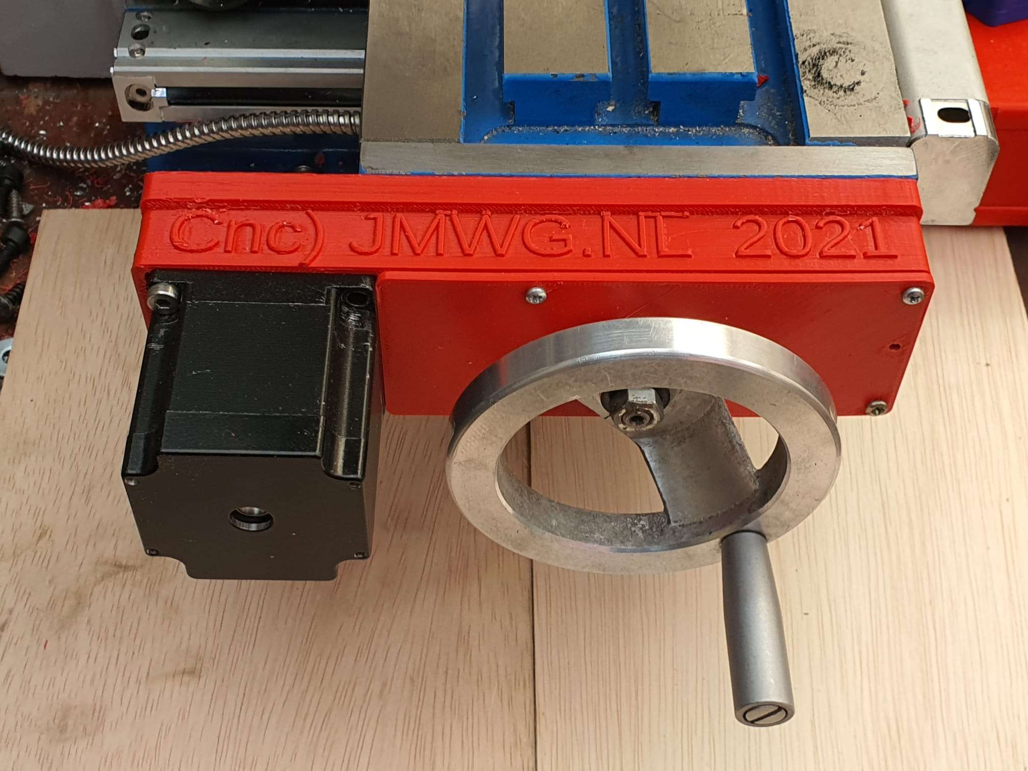
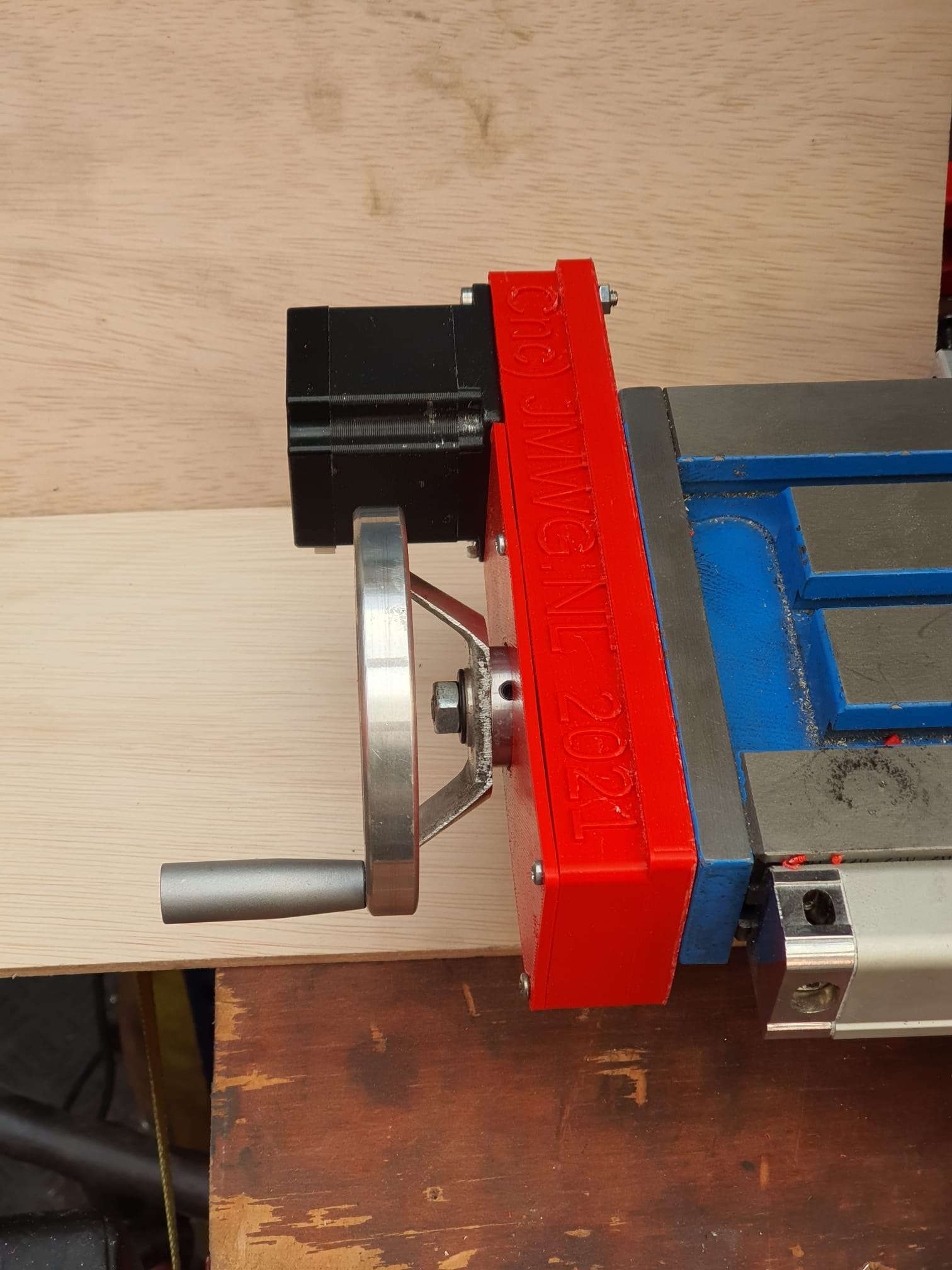
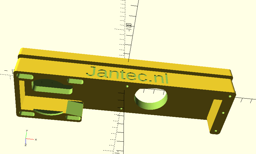
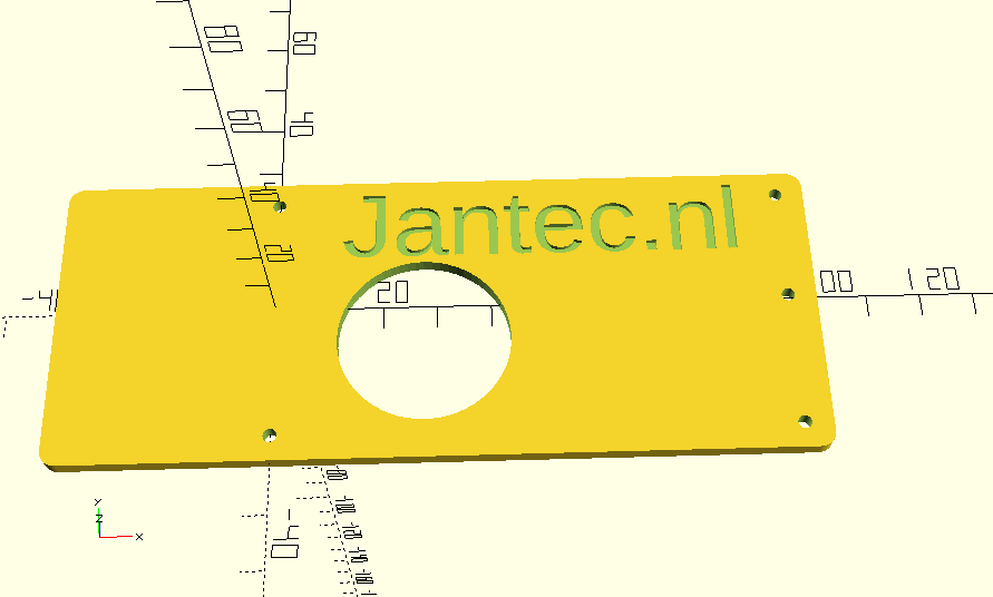
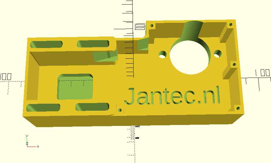
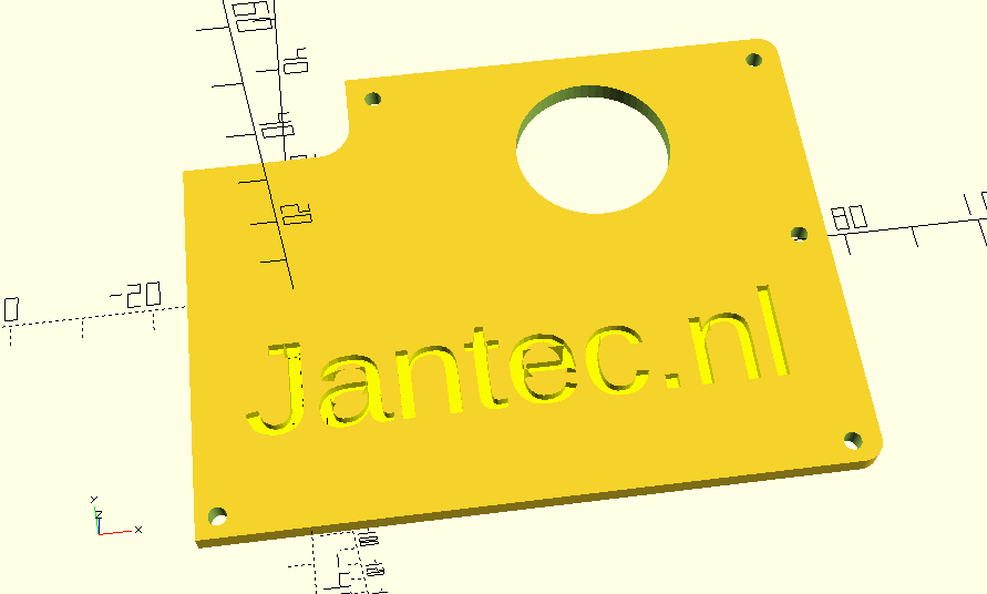
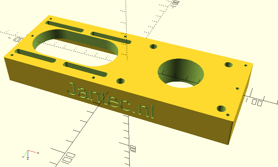
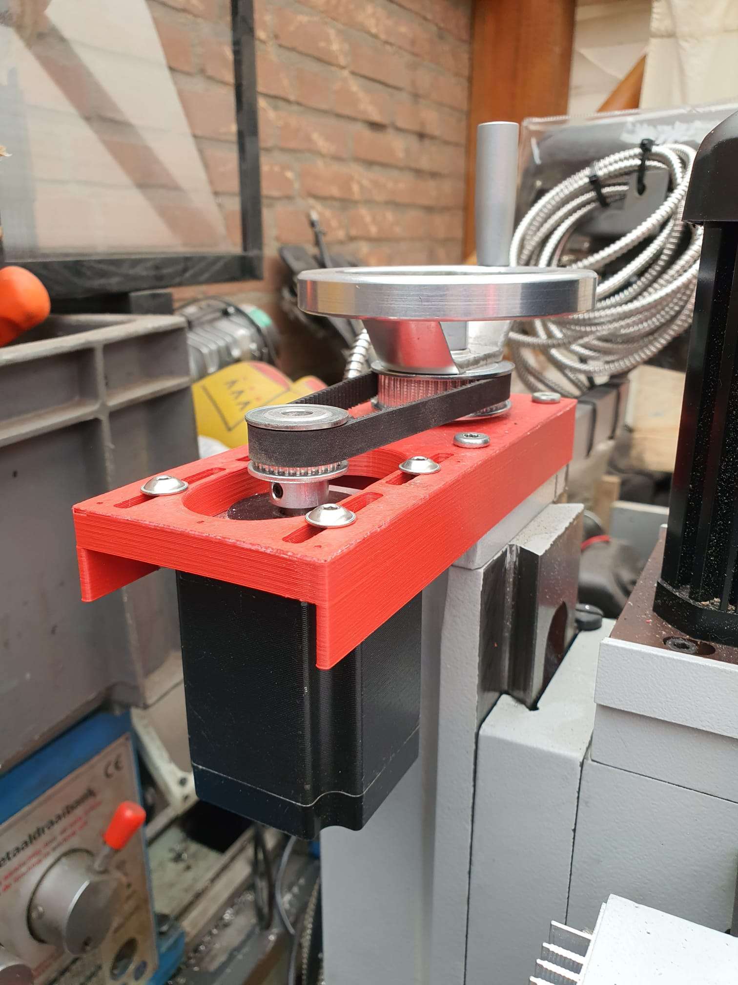
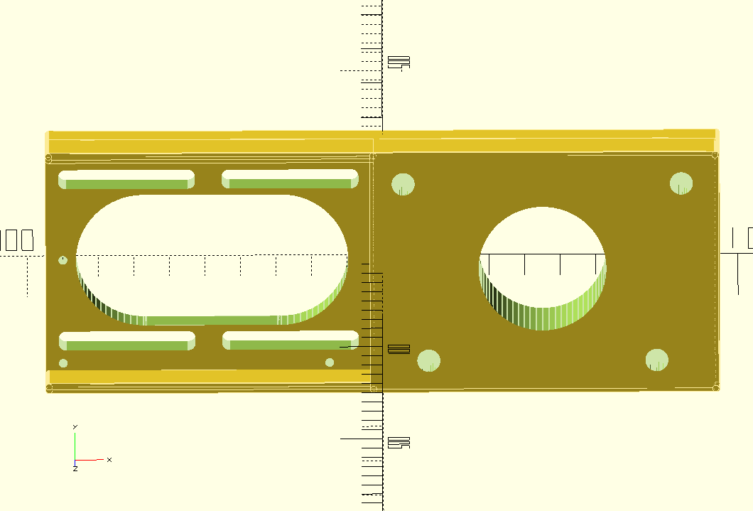
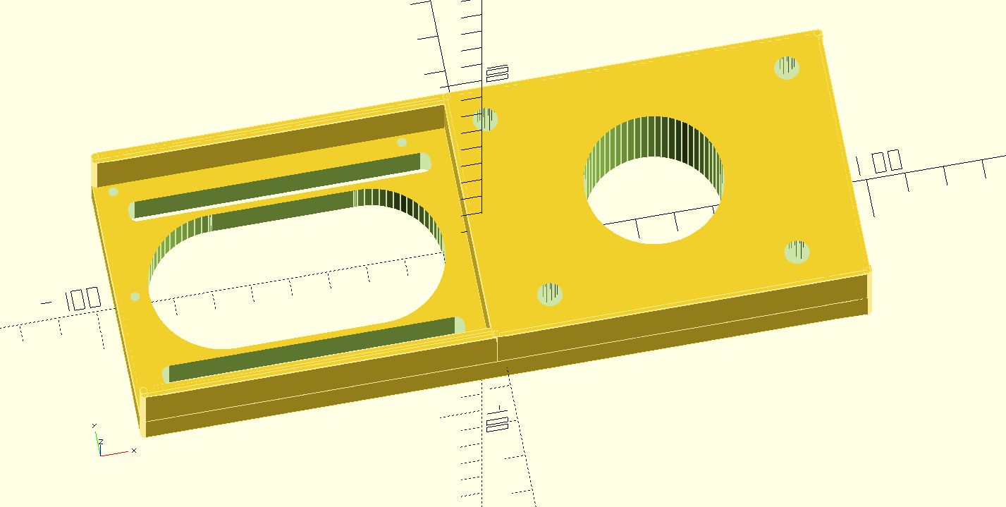
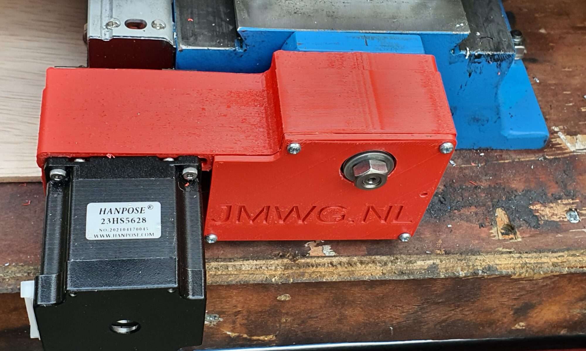
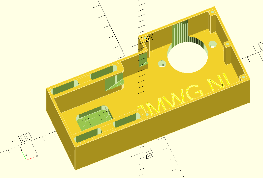
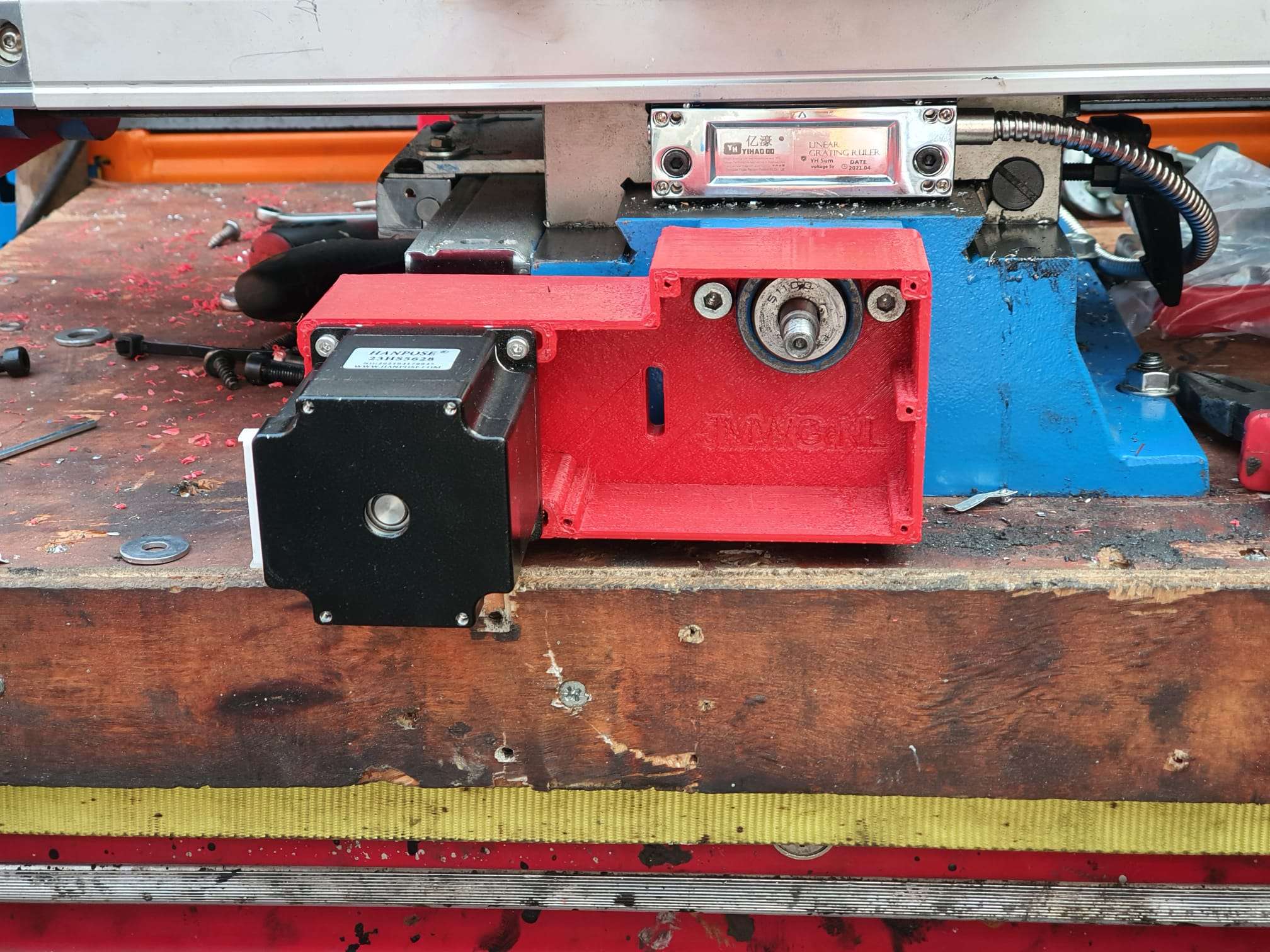
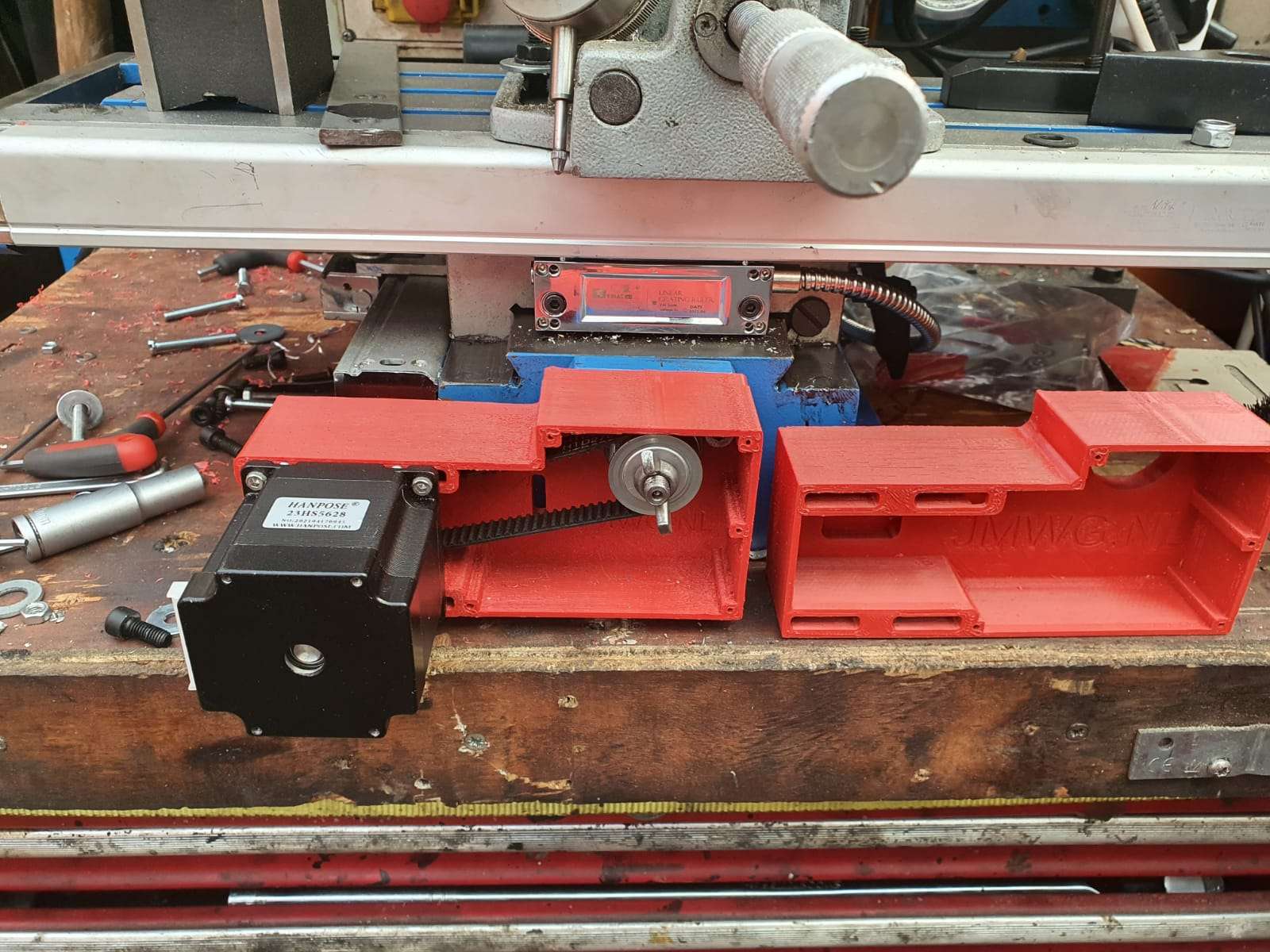
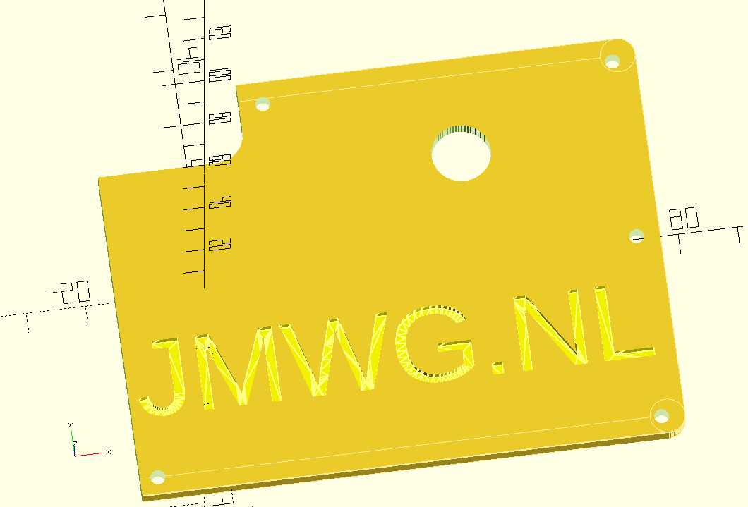
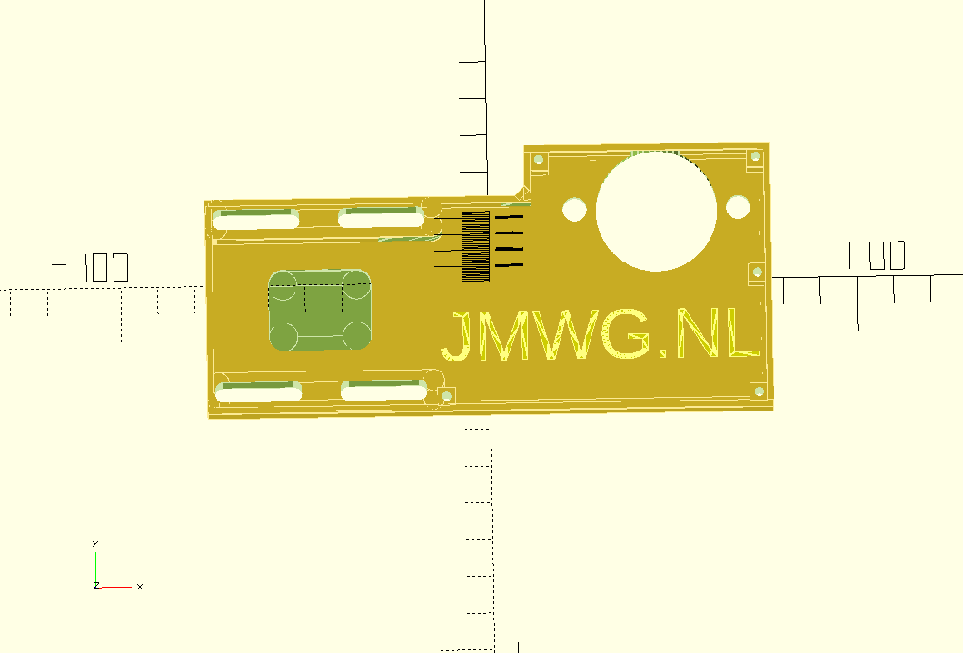
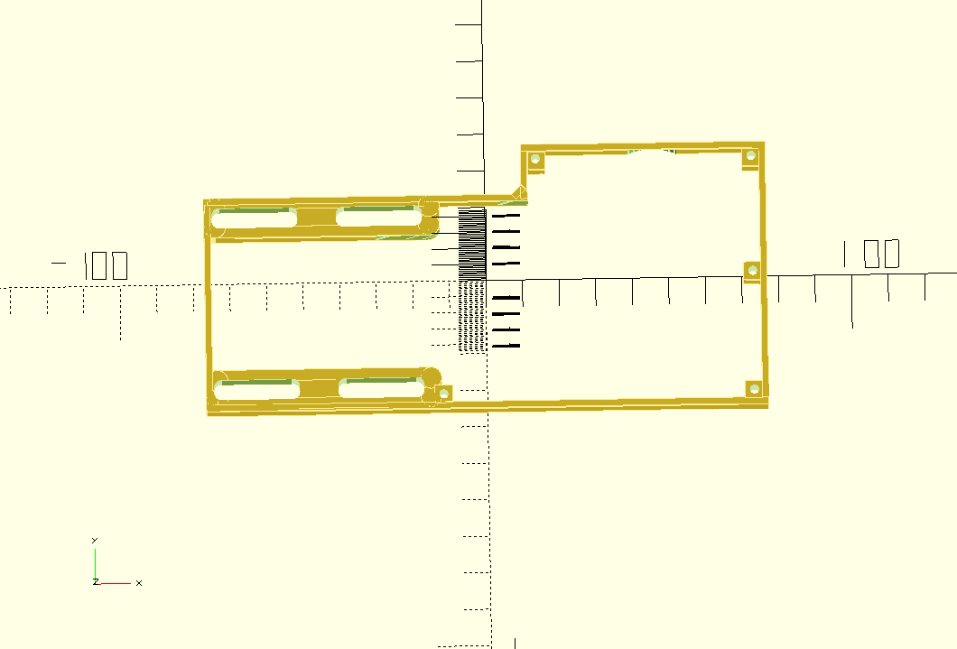
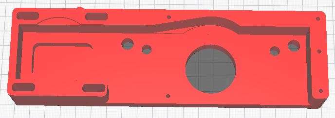
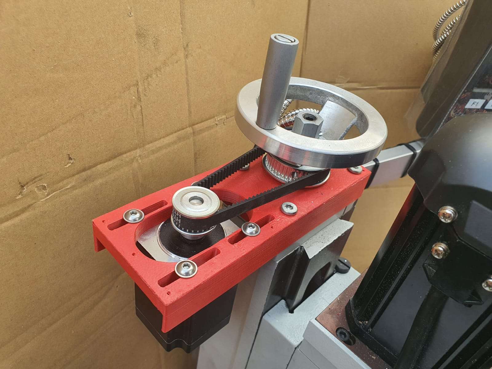
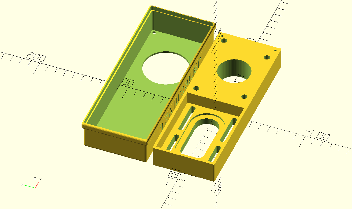
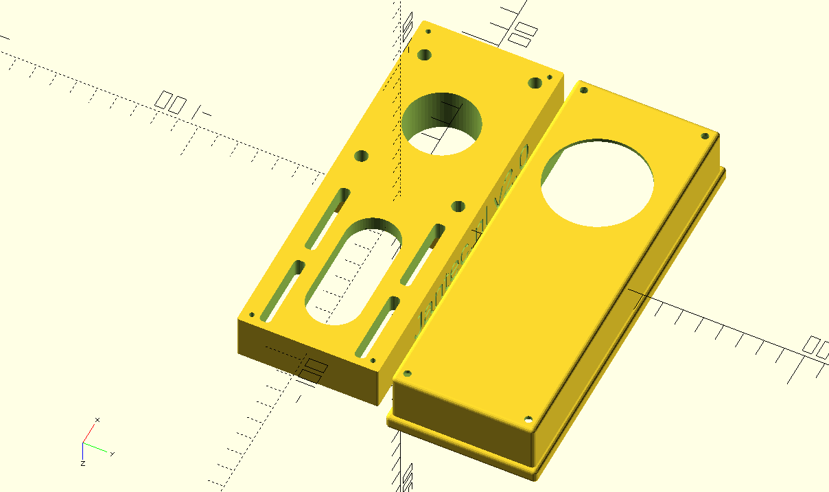
On the net I was unable to find any plug and play sensor holders for my mill, so I developed these holders again from scratch in OpenScad.

Fortunately, I have a lot of starting material in OpenScad from my previous projects.

The X axis left:


The X axis right hand side:


The Y axis front:


The Y axis rear:


The Z-axis top:


Minimill CNC conversion WMD16LV Z-axis adapter for NEMA23 and M3 teethed belt

New stronger version V2 made, also including a top cover 2025,04-24. Will update with pictures after install on the minimill.

MINIMILL_BF16L CNC_Z_adapter belt driven 2025_05_24_V2 Jantec.nl

Please donate $1 to my paypal account if you use (parts of) my developed materials so I can continue to share nice stuff for you to download

:

First working version

The mount on the Z-column needed to get UP so the NEMA23 teethed wheel gets at the same level as the wheel that is mounted on the leadscrew.

Required hardware:

  • 3d printed Z-axis adapter
  • Nema23 stepper 76 mm length with enough torque, 8mm axle diameter
  • 48teeth M3 teethed  wheel of 11mm width, 10mm hole with collar for the leadscrew
  • 24 teeth M3 teethed wheel 11mm width , 8mm hole with collar for the Nema23 stepper motor
  • new M6 40mm length bolts flathead for the top connection to the Z column
  • 4 bolts and nuts M5 to mount the Nema 23 stepper
  • teethed belt 300mm M3 (100 teeth) 9 or 10mm

OR, use the 72 teethed wheel on the leadscrew and get a larger length belt of (I  estimate) 330-350 mm

OR.. another way to mount the Nema23stepper is at the rear of the Z column, BUT I don’t want it to stick out at the rear, that’s why I decided to mount the stepper at the left of the Z-column…

This is the 72 teeth 11 mm width teethed wheel that I will probably use for the final mount at the Z-axes. But not with this bracket at the rear. Unfortunately this bracket does not easily fit at the left or right side of the Z-column. I might make a fitting piece to mount it at the left, though. We’ll see how good the 3d printed parts will perform and if needed the Z-axis will be the easiest to use a standard bracket for mounting the stepper motor as shown above.

GOTO the X axis adapter

GOTO the Y axis adapter

DOWNLOAD THE CNC ADAPTER DESIGNS  as STL

Please donate $1 to my paypal account if you use (parts of) my developed materials so I can continue to share nice stuff for you to download

STL download  for the belt driven adapters of the WMD16LV minimill and Nema23 

Please donate $1 to my paypal account if you use (parts of) my developed materials so I can continue to share nice stuff for you to download

CLICK on the URL to start the download of the corresponding STL file

DOWNLOADS Y-adapter (LEFT SIDE):

MINIMILL_BF16L CNC_Y_adapter belt driven 2023_04_23_V1 Jantec.nl MINIMILL_BF16L CNC_Y_adapter LID belt driven 2023_04_23_V1 Jantec.nl


DOWNLOADS X-adapter (FRONT SIDE):

MINIMILL_BF16L CNC_X_adapter belt driven 2023_04_23_V1 Jantec.nl MINIMILL_BF16L CNC_X_adapter LID belt driven 2023_04_23_V1 Jantec.nl


DOWNLOAD Z-adapter (TOP):

MINIMILL_BF16L CNC_Z_adapter belt driven 2023_04_23_V1 Jantec.nl


GOTO THE MINIMILL PAGE

Minimill CNC conversion WMD16LV X-axis adapter for NEMA23 and M3 teethed belt

NEW VERSION with debree screen:

You can 3dprint the entire bottom and debree screen with the risers for the stepper motor at once, as I did in red ABS at 270 degrees C

For this setup you need

  • 1 piece Nema23 56 length stepper motor with 6.35 mm axis
  • 1  piece 12-teethed M3 wheel with collar, hole dia 6.35 mm, 11 mm width
  • 1  piece 24-teethed M3 wheel with NO collar, hole dia 10 mm, 11 mm width
  • Teethed M3 belt , 9 mm wide and length 255 or 275 mm (need to check this)
  • 3d printed parts
  • M8 rings and nut

Here the connection is shown onto the X-axis/ leadscrew bearing holder with 2 M6 bolts.

And front lid:

And the Milling design for the base plate for CNC machining in aluminium should you prefer this.

The 3D print file for the debree cover and the stepper motor risers, to be placed on the aluminium milled base plate:

GOTO the Y axis adapter

GOTO the Z axis adapter

DOWNLOAD THE CNC ADAPTER DESIGNS  as STL

Please donate $1 to my paypal account if you use (parts of) my developed materials so I can continue to share nice stuff for you to download

Minimill CNC conversion WMD16LV Y-axis 3d printed adapter for NEMA23 and M3 teethed belt

The design for the Y-axis mounting plate for the Nema23 stepper  is shown below and can be 3dprinted or, as I will do after the printed part proves to fit well, CNC it in aluminium on my CNC Indymill router.

The Y-axis adapter proved to be the most difficult design.  It took me 15 trial prints before I got everyting fully optimized.  And I also wanted to have a debree screen with a removable lid, which took some energy to test this.  Also, the belt has to have a clean route where it sits between the wheel.

The physical data for this setup:

  • Nema23 stepper motor
  • 3d printed parts: a: Baseplate inclusing risers for motormount and shield; b: lid
  • Teethed wheel for the Nema23 8mm axle: 10mm wide, 24 teeth M3 with chest
  • Teethed wheel for the leadscrew 10mm axle: 10mm wide: 48 teeth M3 with chest, machined on the teethed inside 9mm depth with a  width of 33 mm diameter to fit the chest of the leadscrew bearing holder
  • The fitting belt is 9mm wide, 300 mm long and has 100 teeth (M3)

GOTO the MiniMill’s X-axis CNC Nema23 mounting plate

GOTO the MiniMill’s Z-axis CNC Nema23 mounting plate

FINAL DESIGN:

Machined the inner part out on the lathe so it will slide for about 9mm over the Y axis’ leadscrew bearing holder

And now the wheel can move over the bearing holder to the right
This saves 9mm mounting space and now the machined handwheel can be replaced, if so desired.  But the handwheel needs to be machined first, to get the dial off.

the small holes can be used to place the lid on the debree screen with small 2.5 mm dia screws  Or, you van leave the lid off and put a wheel on as I have done on the Z-axis.  You must machine the dial off the wheel so it gets thin enough to mount on the remaining M8 leadscrew-end.  A little part of the 10mm shaft will stick out  with my method to keep the handwheel centered.

GOTO the X axis adapter

GOTO the Z axis adapter

DOWNLOAD THE CNC ADAPTER DESIGNS  as STL

Please donate $1 to my paypal account if you use (parts of) my developed materials so I can continue to share nice stuff for you to download

3d Printers – overview

At the moment (2025-07) I have the following 3d printers up and running:

  1. Voron 2.4 300x300x300 extremely fast ABS/ASA printer
  2. Voron 2.4 R2 CANBUS_TAP 600x600x500 VERY BIG & FAST ABS  printer
  3. Twotrees Sapphire Pro ‘enclosed’ very fast ABS/ASA printer
  4. Prusa mini very good for PETG primarily
  5. I3 Prusa Bear DIY Fly-CDY-V2 with dual Z axes, 0.6mm nozzle for PLA/ PETG
  6. I3 Prusa Bear ‘plus’ DIY with dual magnetic carriages and sensorless Xhoming
  7. A30M Duet2wifi Geetech dual extruder switchable mono or dual head
  8. Delta G2S Duet2wifi Geetech single head speedprinter 0.8 mm nozzle
  9. Kingroon KP3 mini with full extension package (rails, extruder, firmware..)
  10. Flashforge adventurer 3 all-original almost never used
  11. Ender3pro with TT mini e3 V2.1 , workhorse with 0.6 mm nozzle for PETG
  12. Prusa mini clone (but I can’t tell the difference..) for PETG primarily
  13. E3D Toolchanger met 4xHemera DD’s
  14. Mini Monoprice Delta printer
Prusa mini clone

Triple mixing hotend for A30M

Next to the penta non-mixing hotend, I recently bought this mixing triple hotend, to experiment with it on the A30M.  It is not the same as the Geeetech original triple mixing hotend, however it does have some resemblance.

Obviously, this hotend requires 3 extruders via bowden tubes.  The extruders I have are all Chinese clones of the 1:3 geared bondtech extruders.

The 3 extruders will be placed on the top horizontal aluminium frame, right where they are originally placed.  In fact, I am rebuilding the machine like the A30M from Geeetech that has a mixing triple hotend.  But- mine will have the Duet2wifi motherboard instead.

Soon as I install this, I will upload pictures and the config files (and all tool files like tfree, etcetera for the three tools as well).


Hanging 3d printer

My last 3d printer I built just produced too much noise, mainly from changing the tools during multi-filament prints

Finally, I made a construction where the printer hangs in big elastic suspenders.  This took away any noise that was previously transferred to the wall, so no more problems with noises throughout the house.  Pfff…

My mini shop

One of the 2nd floor bedrooms was converted into my 3.5×2  meters mini in-house workshop… The garage is used for my larger machines like the lathes, milling- and welding machines, laser cutter et cetera…

FLY 407 Motherboard RRF3+ wifi + BTT 2.4 inch TFT + multi-extruder

2021-05-11

I got the Mellow Fly 407 board in today, and it now works awesome!

I hooked the Mellow dedicated wifi unit to EXP 1 and EXP2 and to the serial TFT connection, programmed the microSDcard offline on the PC with the files from the proposed Github site and it all went great!  (The little added user manual is very good, just follow the directions and it can’t go wrong!)

Burnt the board’s firmware first, then the firmware of the wifi esp module and after setting up the wifi with YAT via USB, I programmed the wifi settings.  Then, with the Duet’s WDC PC-remote console via wifi, I uploaded the FLY 407 motherboard with all the latest available firmware: RRF3.4 beta and the latest wifi- and DWC versions.

Then, I removed the serial connection between the TFT connection on the motherboard and the wifi module and plugged in the BTT 2.4 inch TFT at the same serial port.  Since there is only 1 tft port available, I use the same serial port as I used for programming the esp wifi module.  I already put the RRF3 firmware on the TFT unit.

Well, the results are awesome! On the TFT after connecting you see the extruder step from 0 to 1-2-3-4 and back to 0 so this all works very nice!

I must be honest here: I also tried the Mellow 7 inch screen but this is not yet really working as well to me as the little BTT screen IMHO.  The Fly screen is a lot bigger, though, and the Fly 7 inch TFT has great potential.  I know that it will also take some getting used to the FLY’s TFT screen layouts.  The access to the macro and gcode directory is nice, but since everything is placed differently than the PanelDue screens, it might just take some time to appreciate it more.