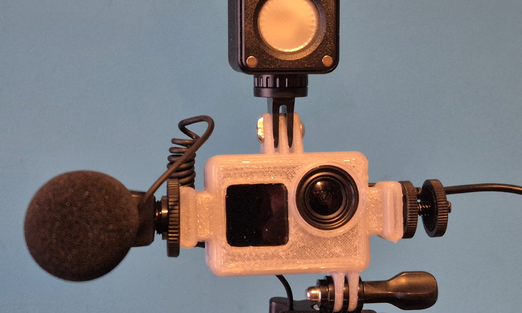
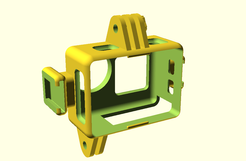
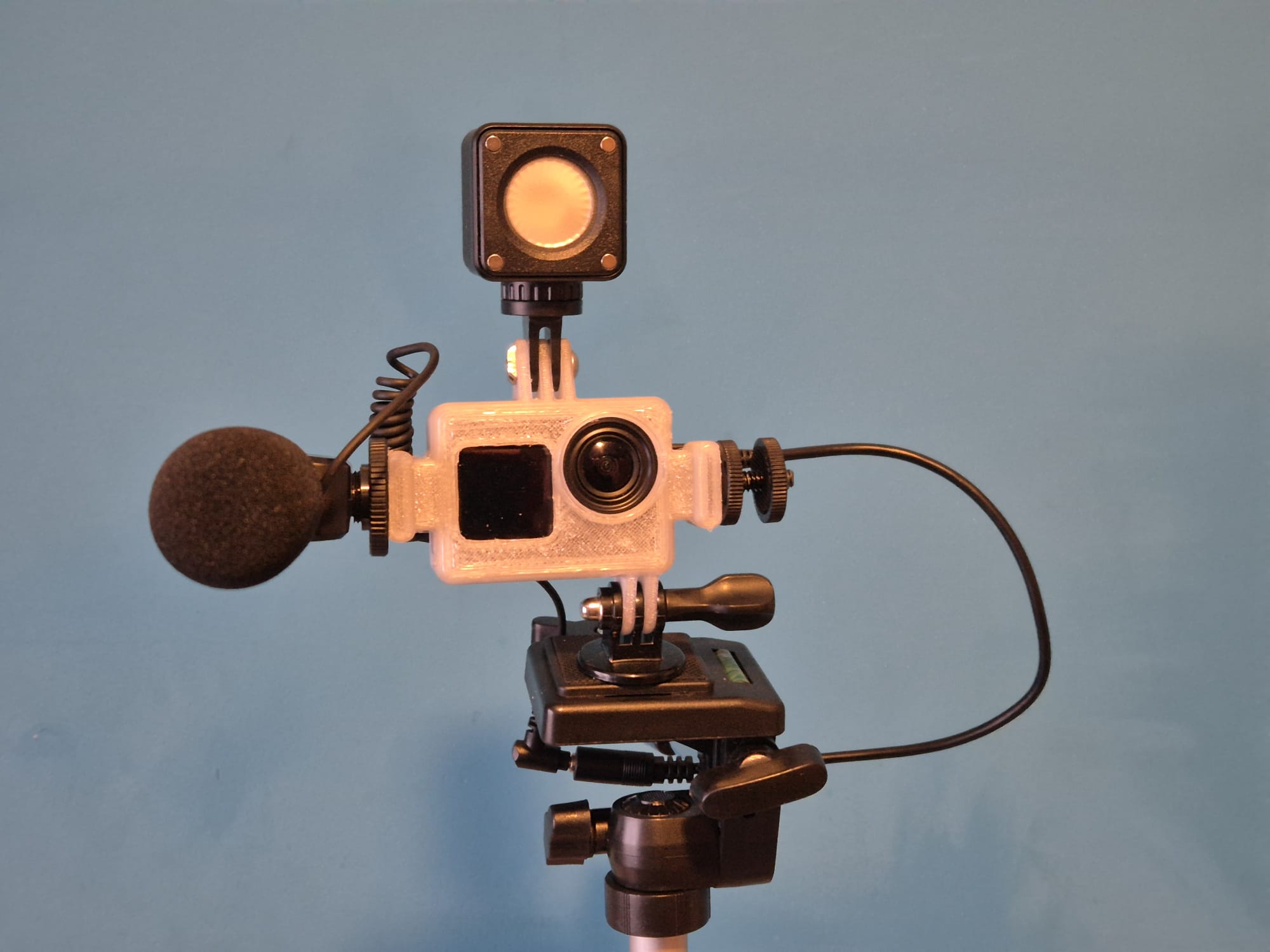
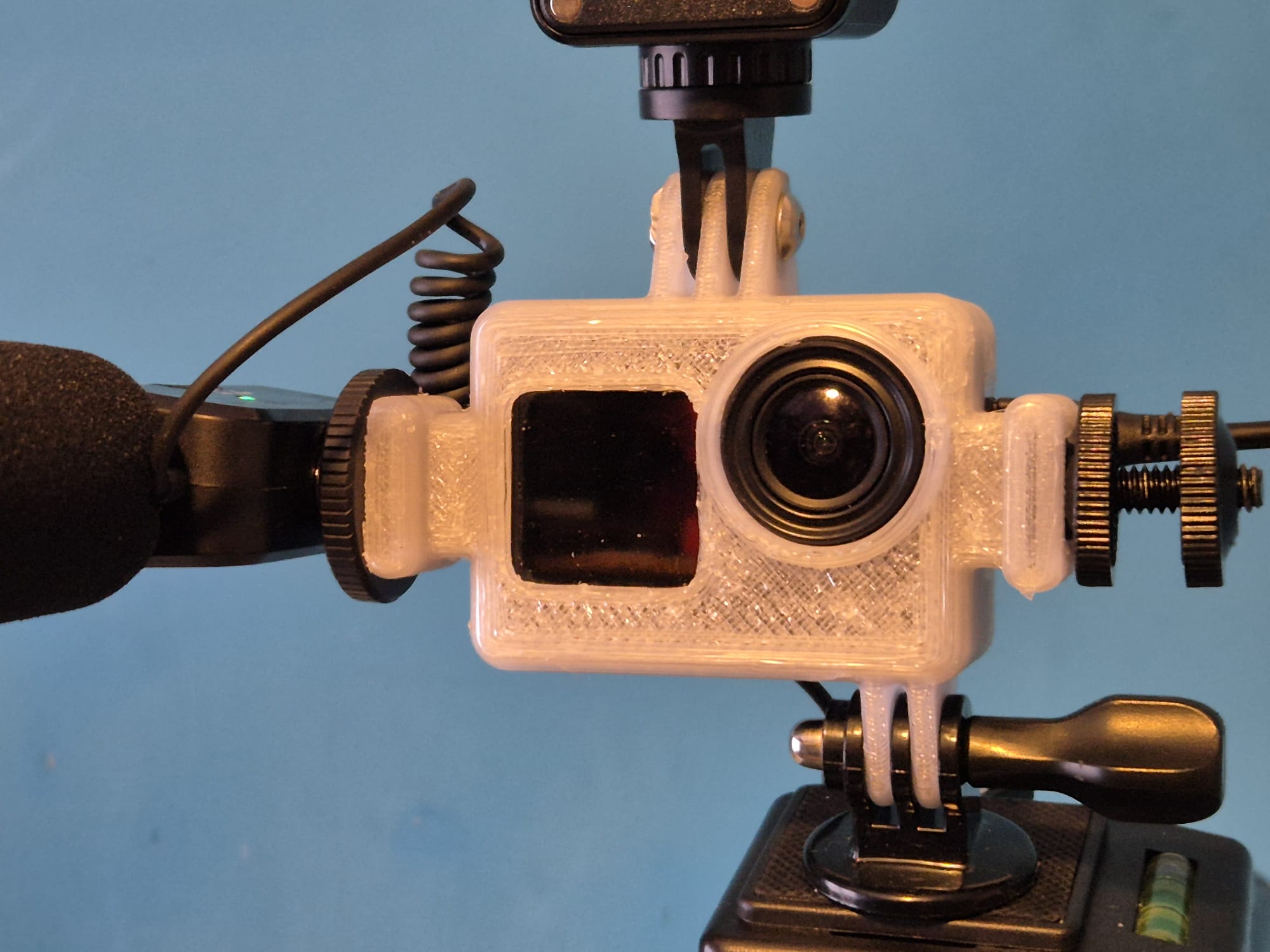
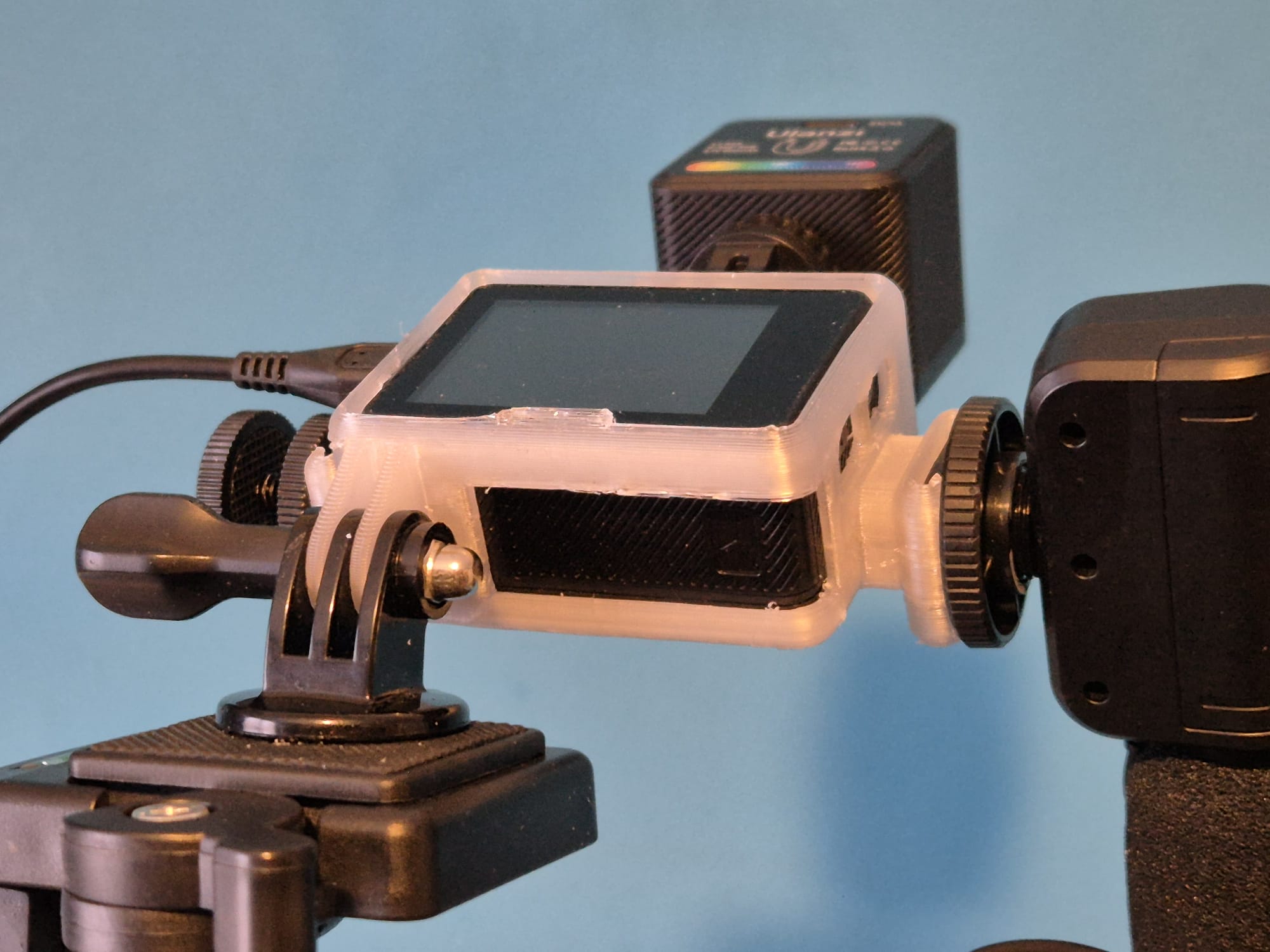
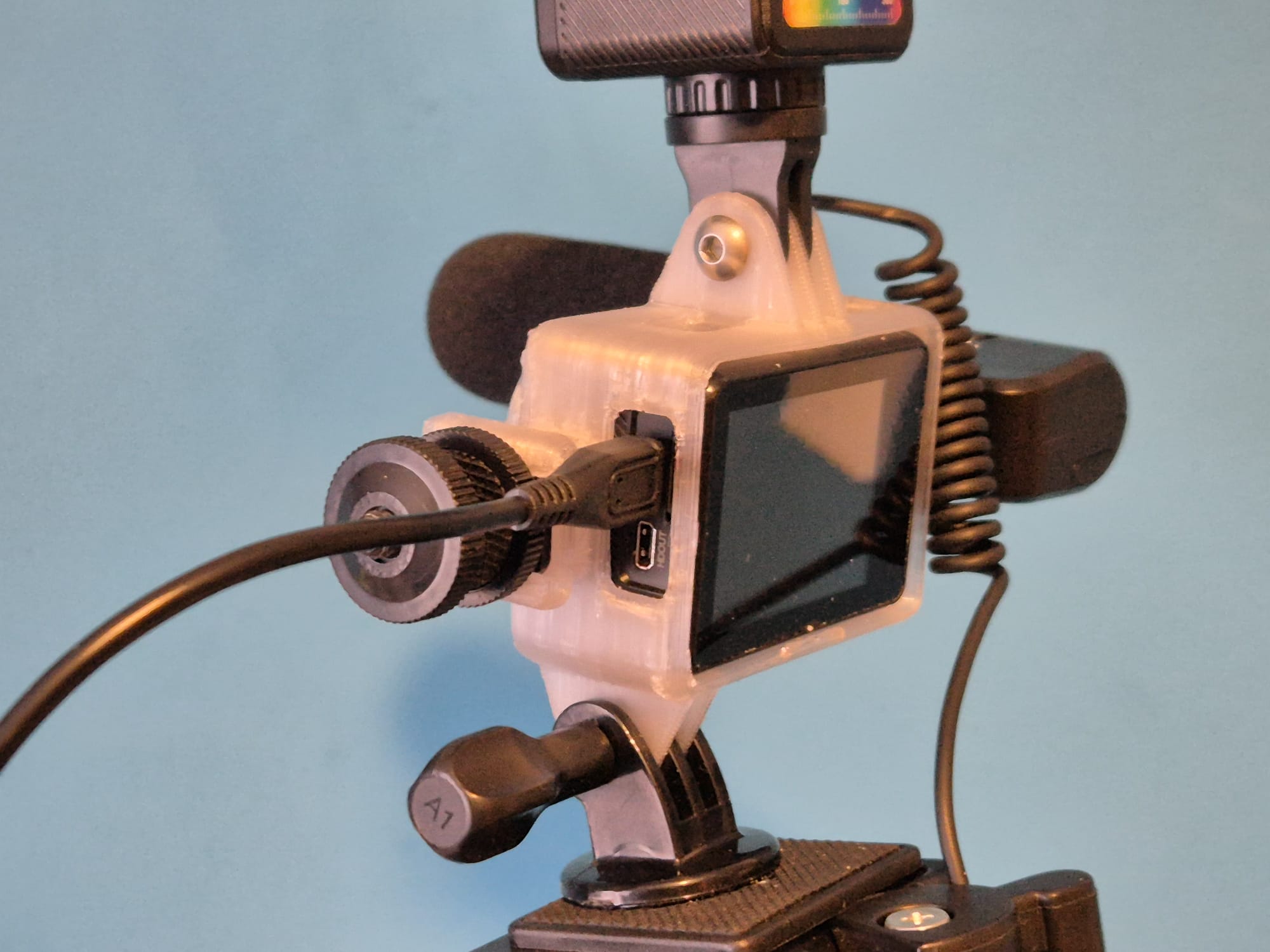
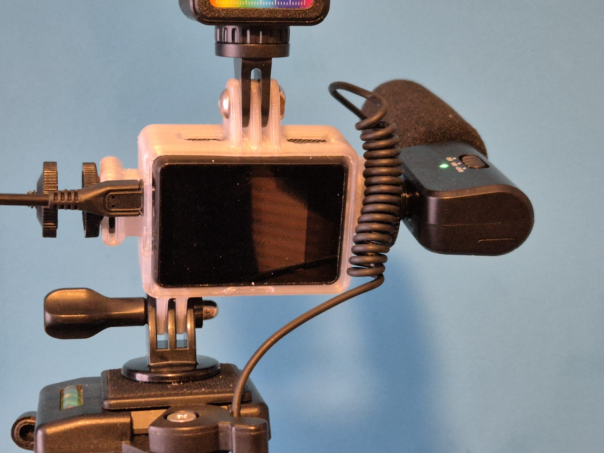
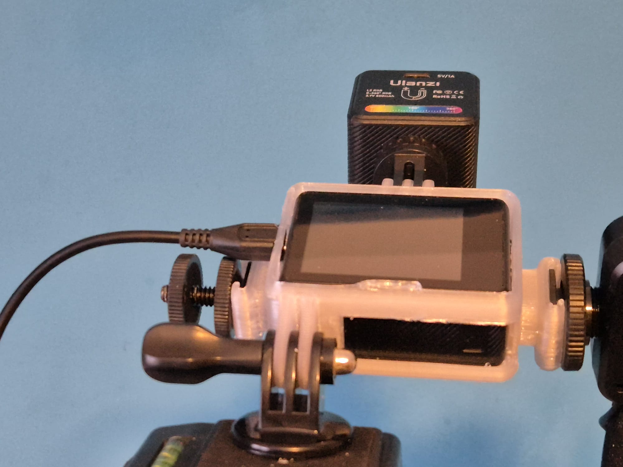
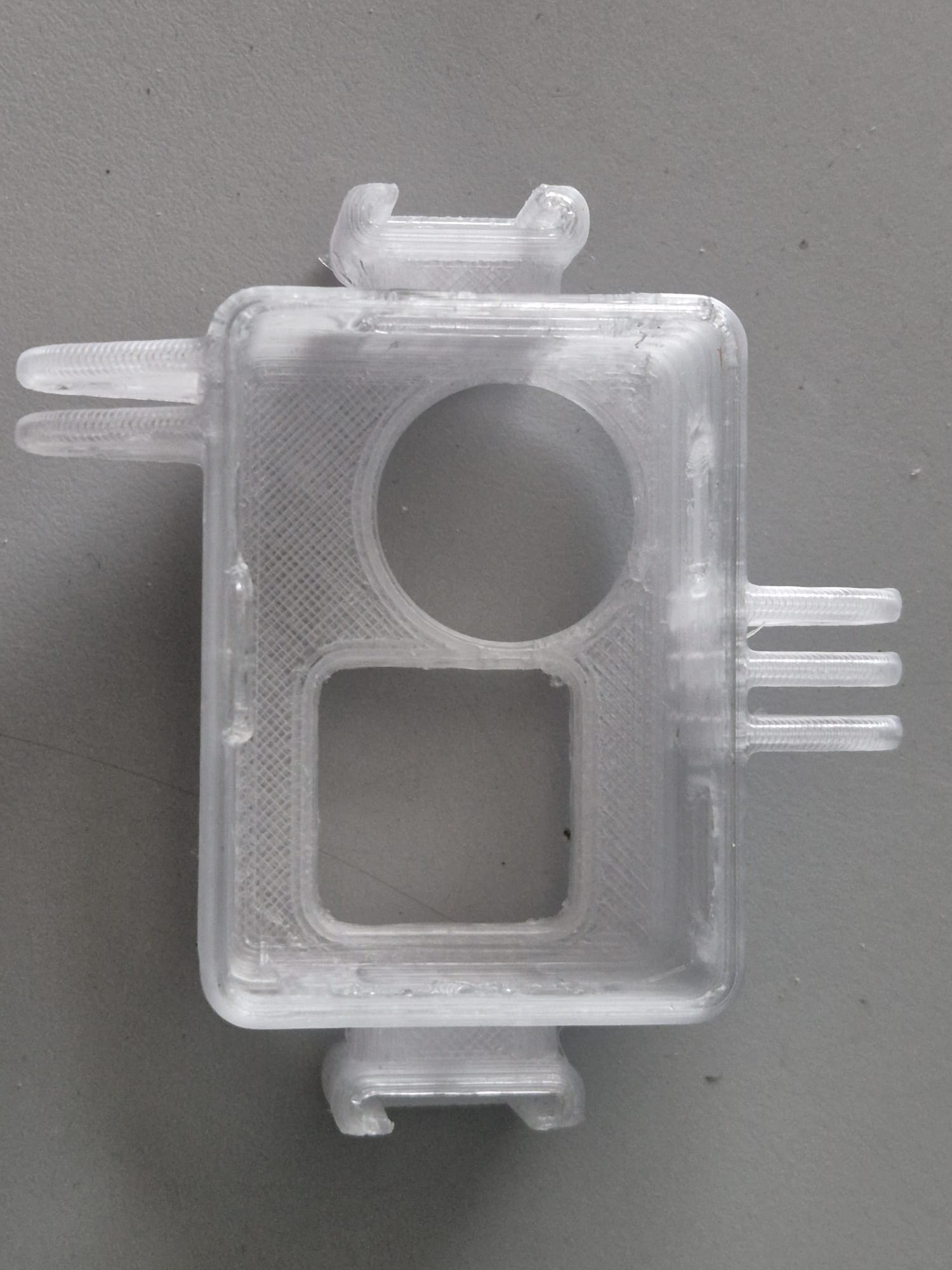
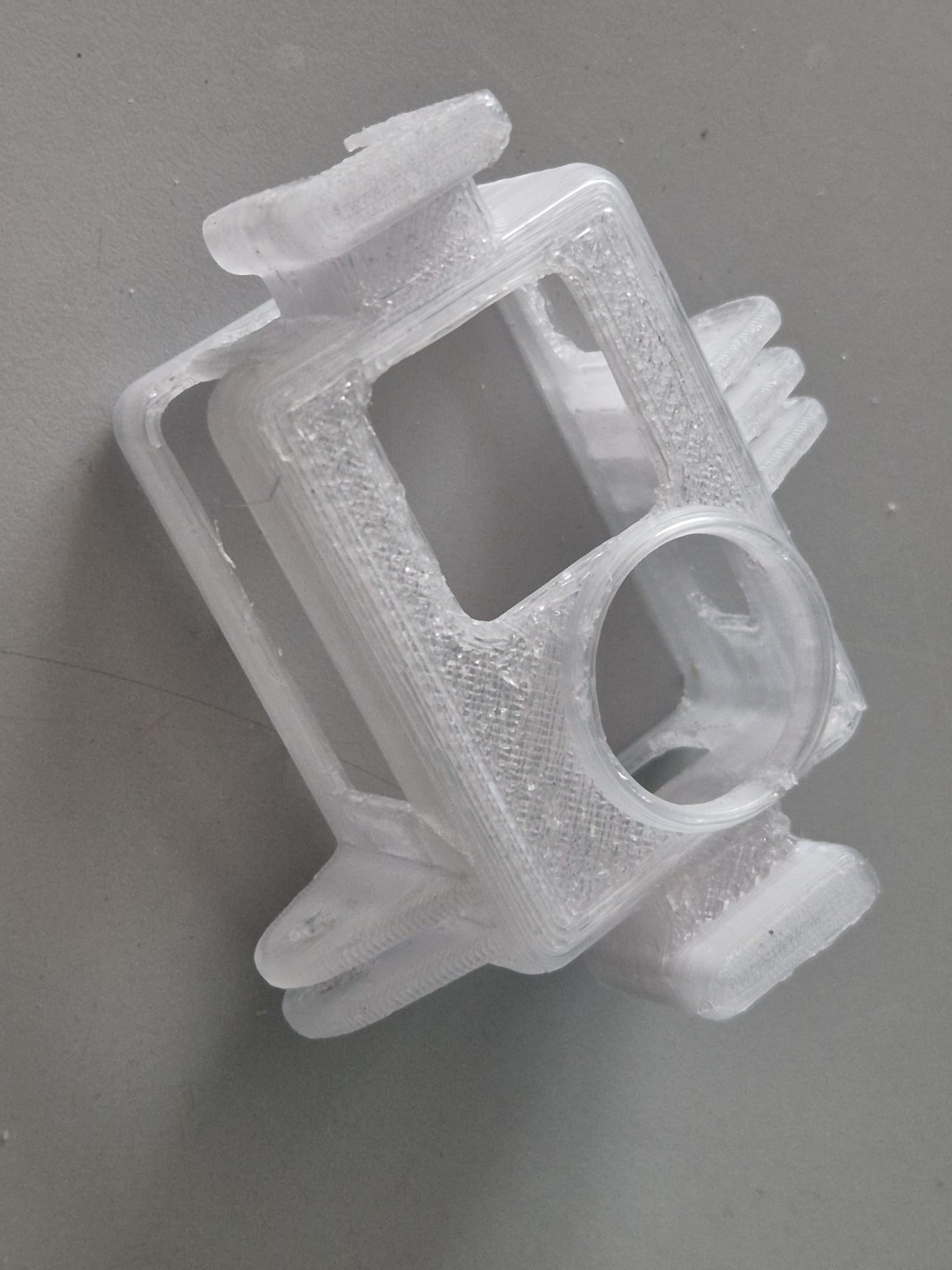
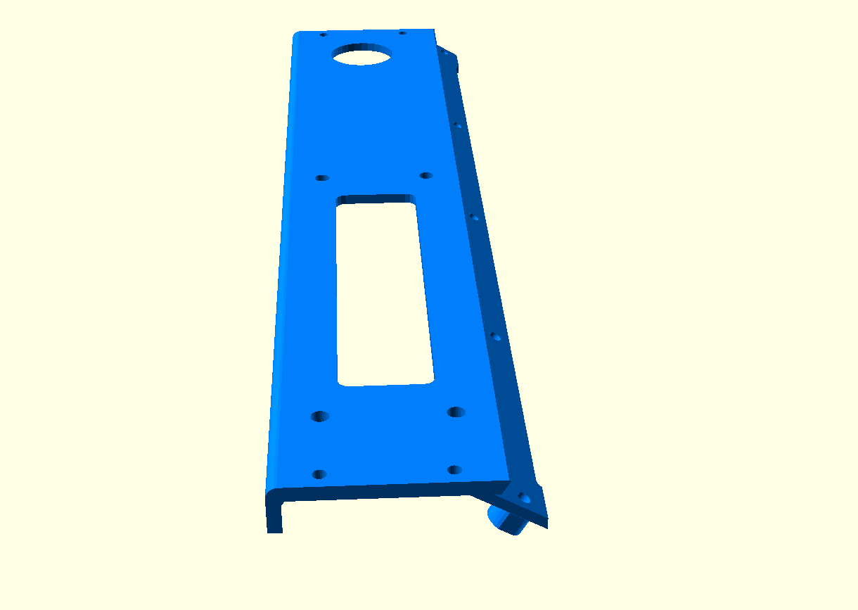
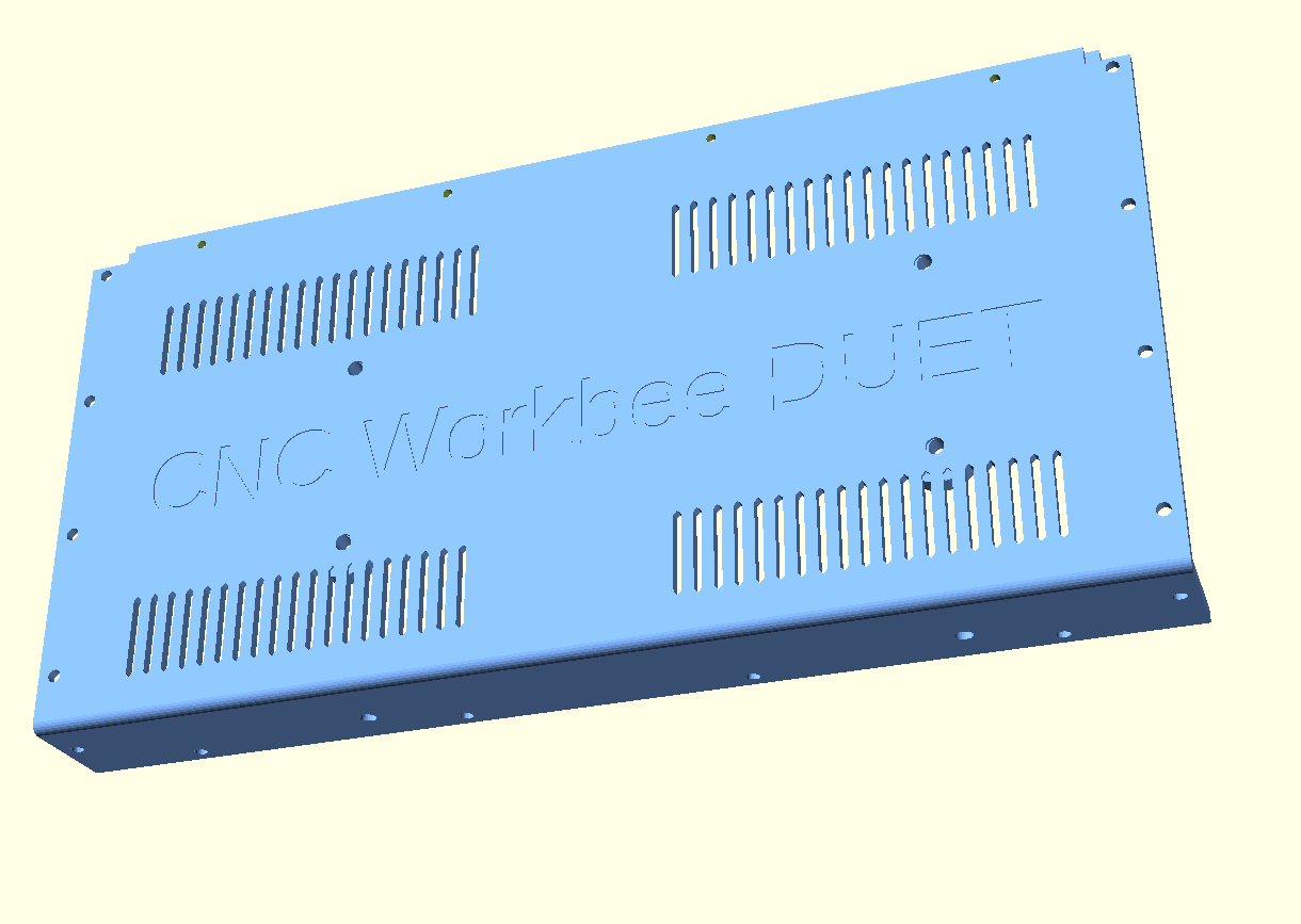
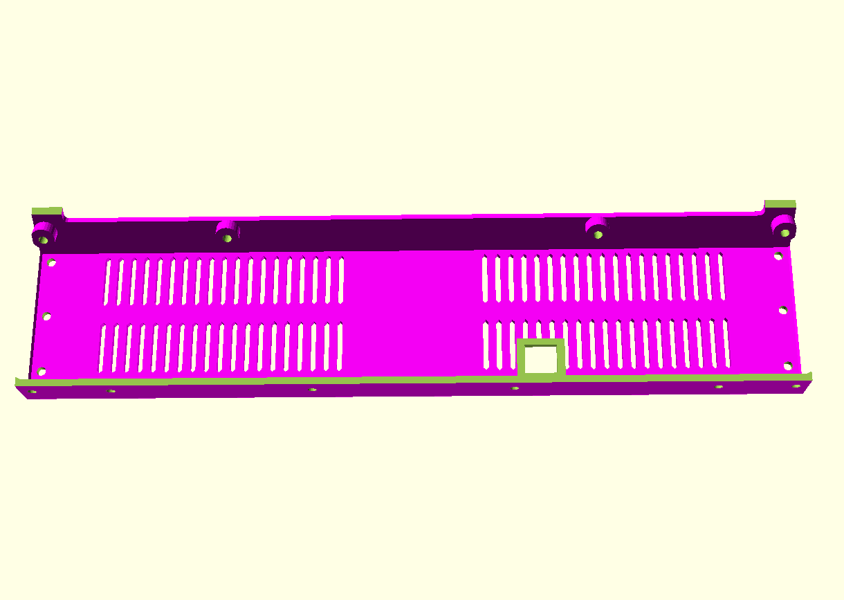
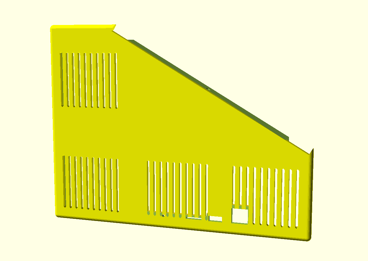
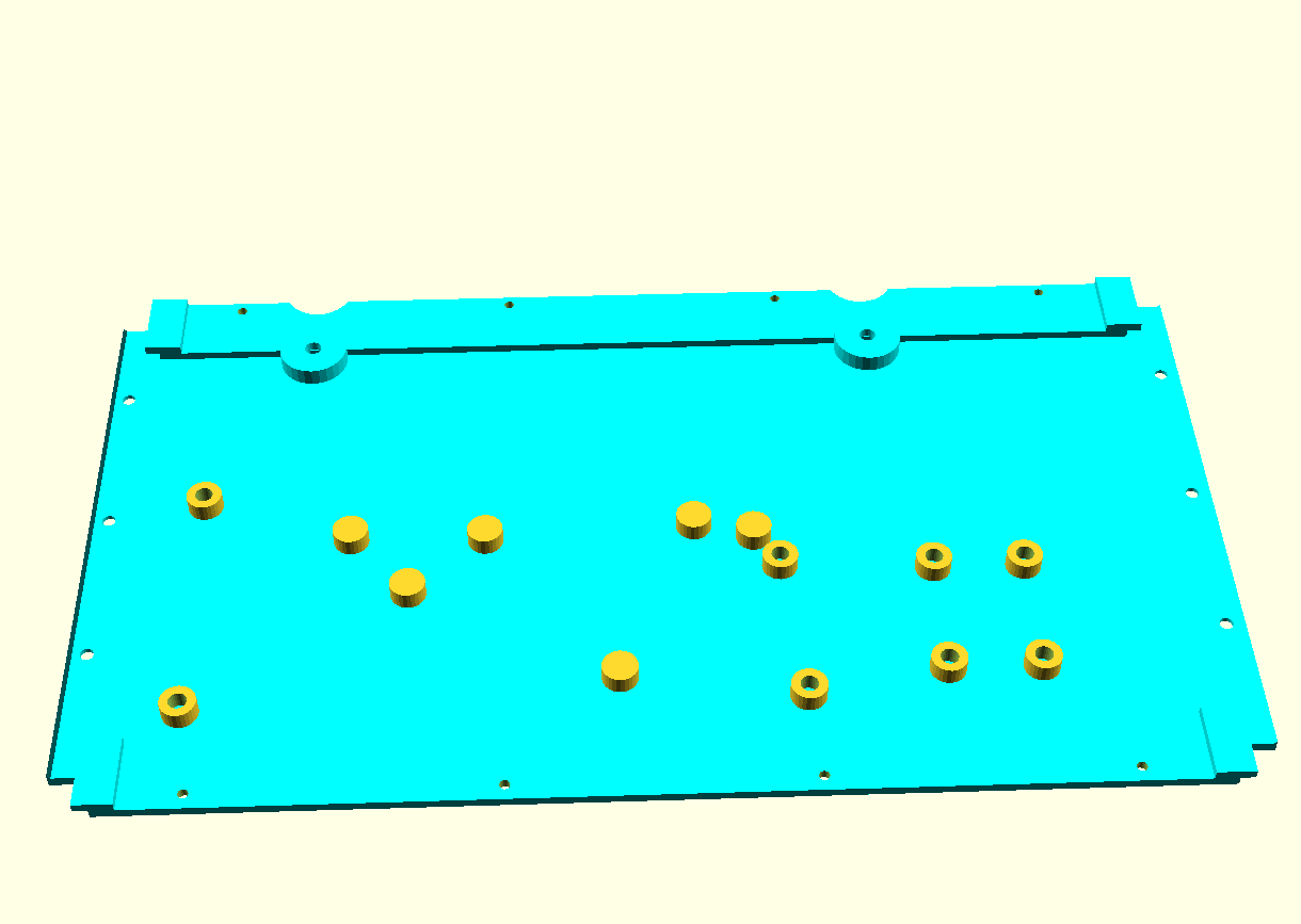
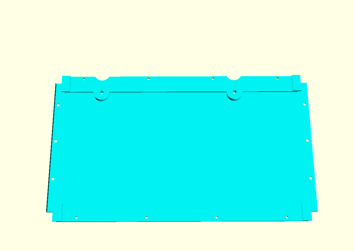
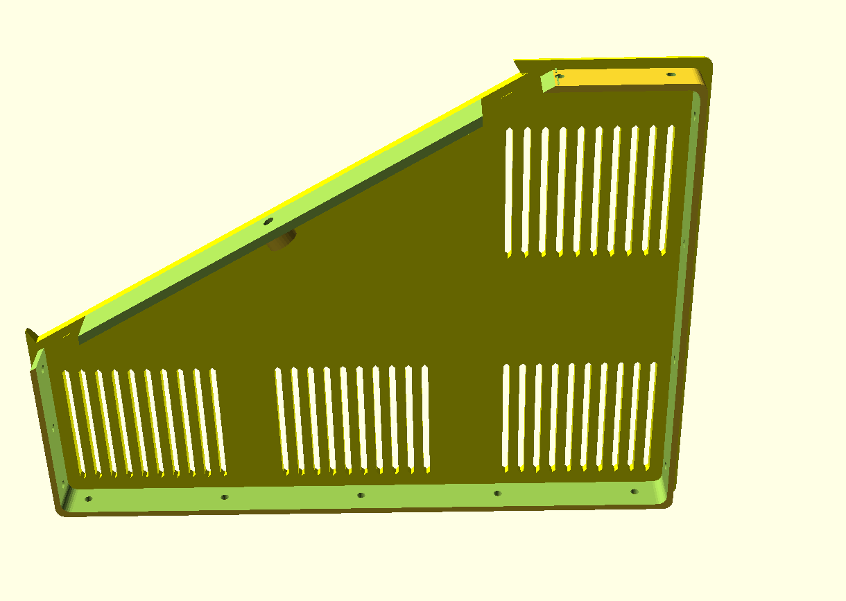
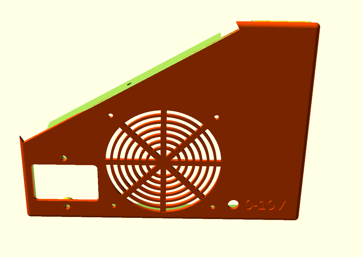
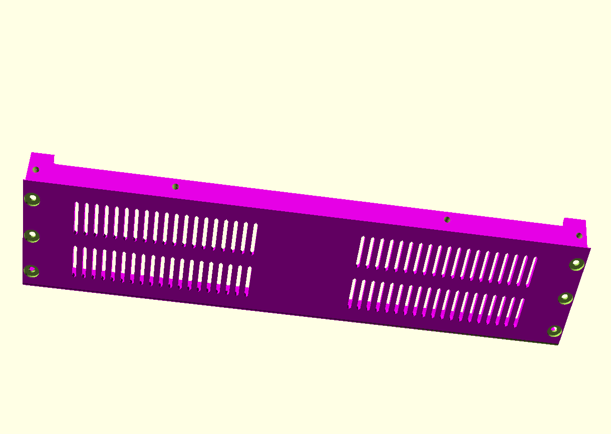
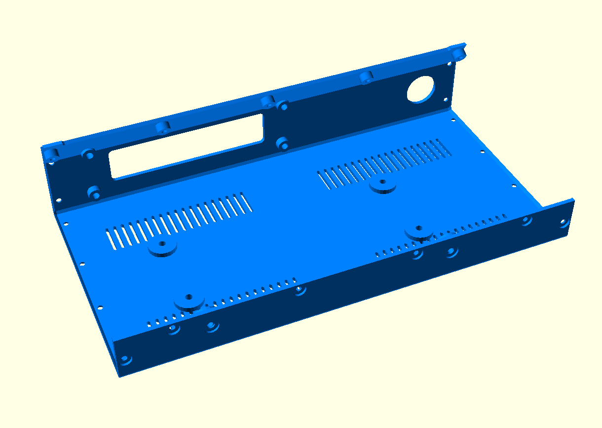
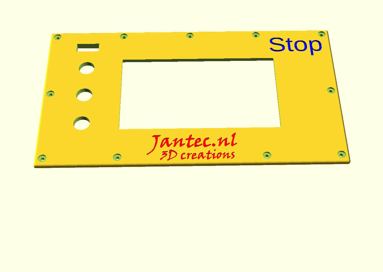
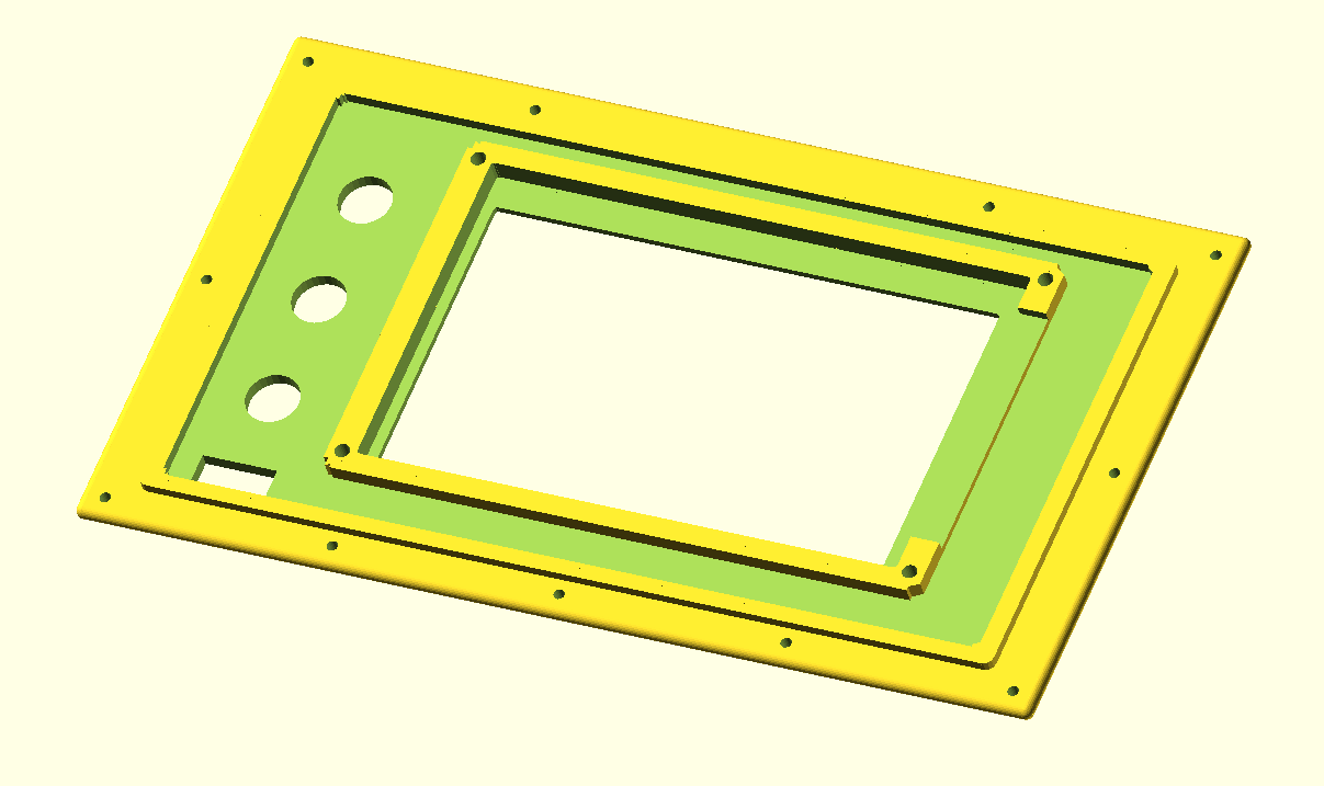
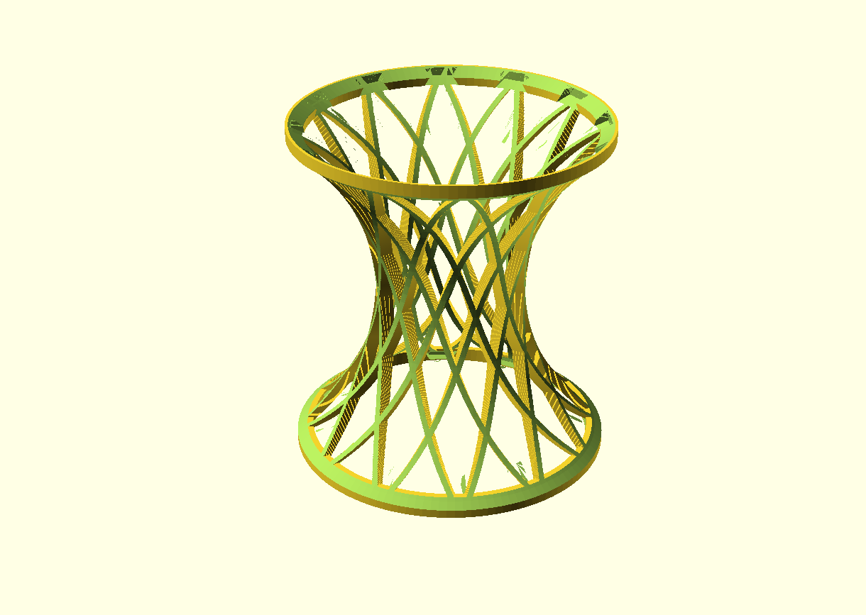
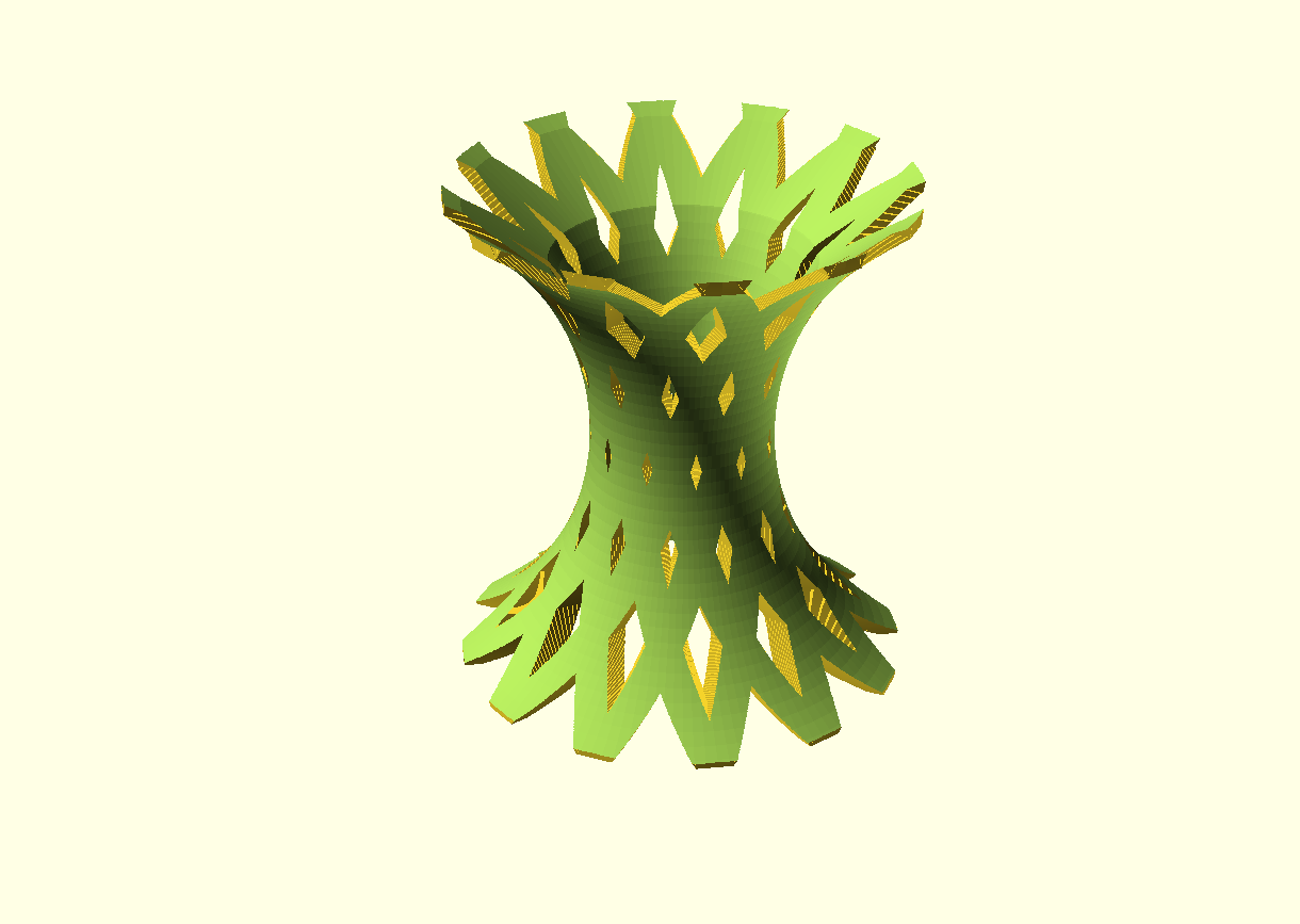
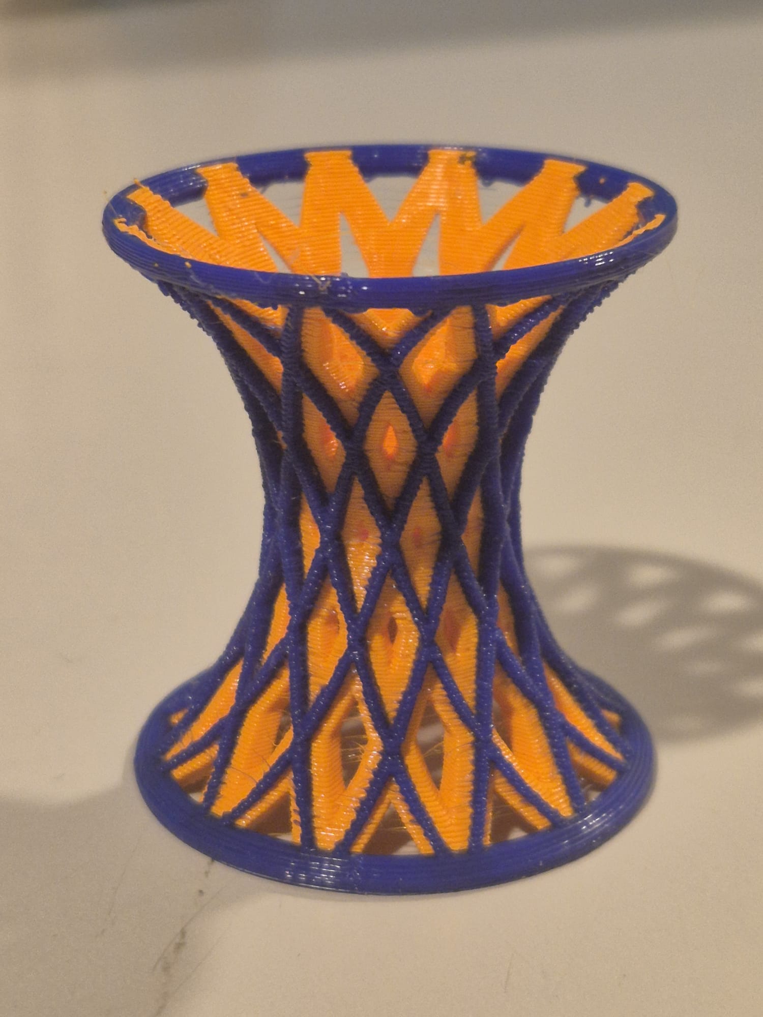
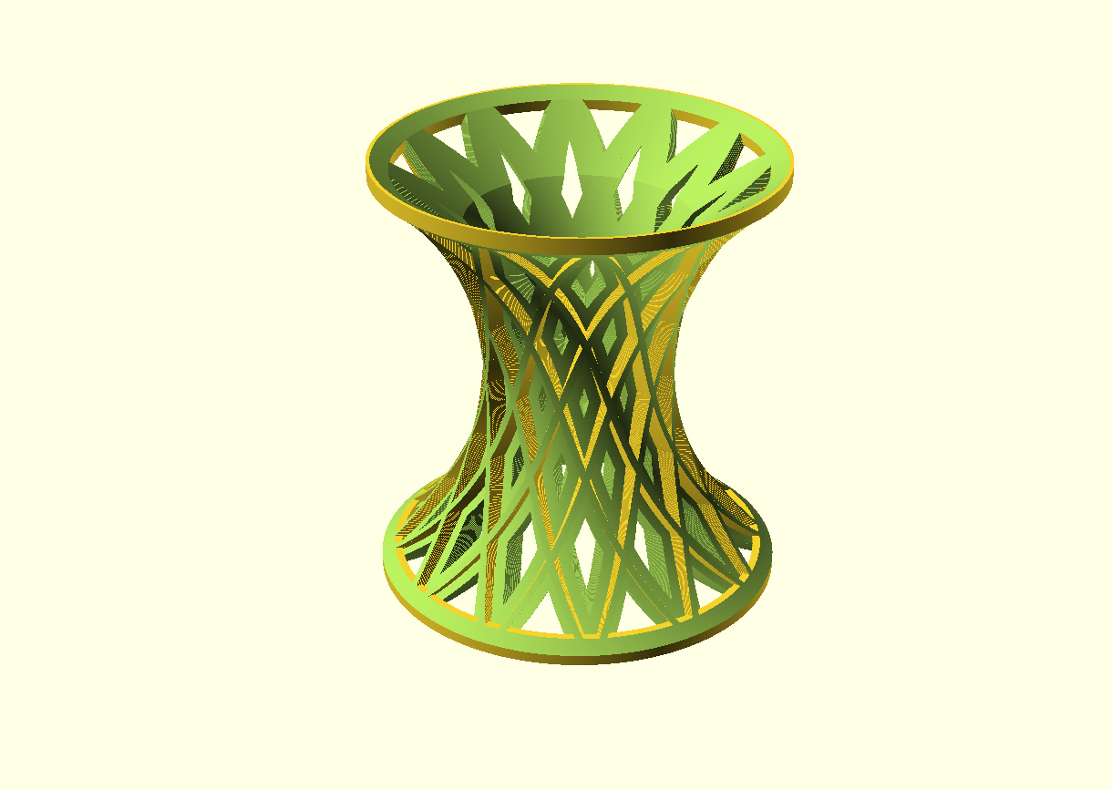
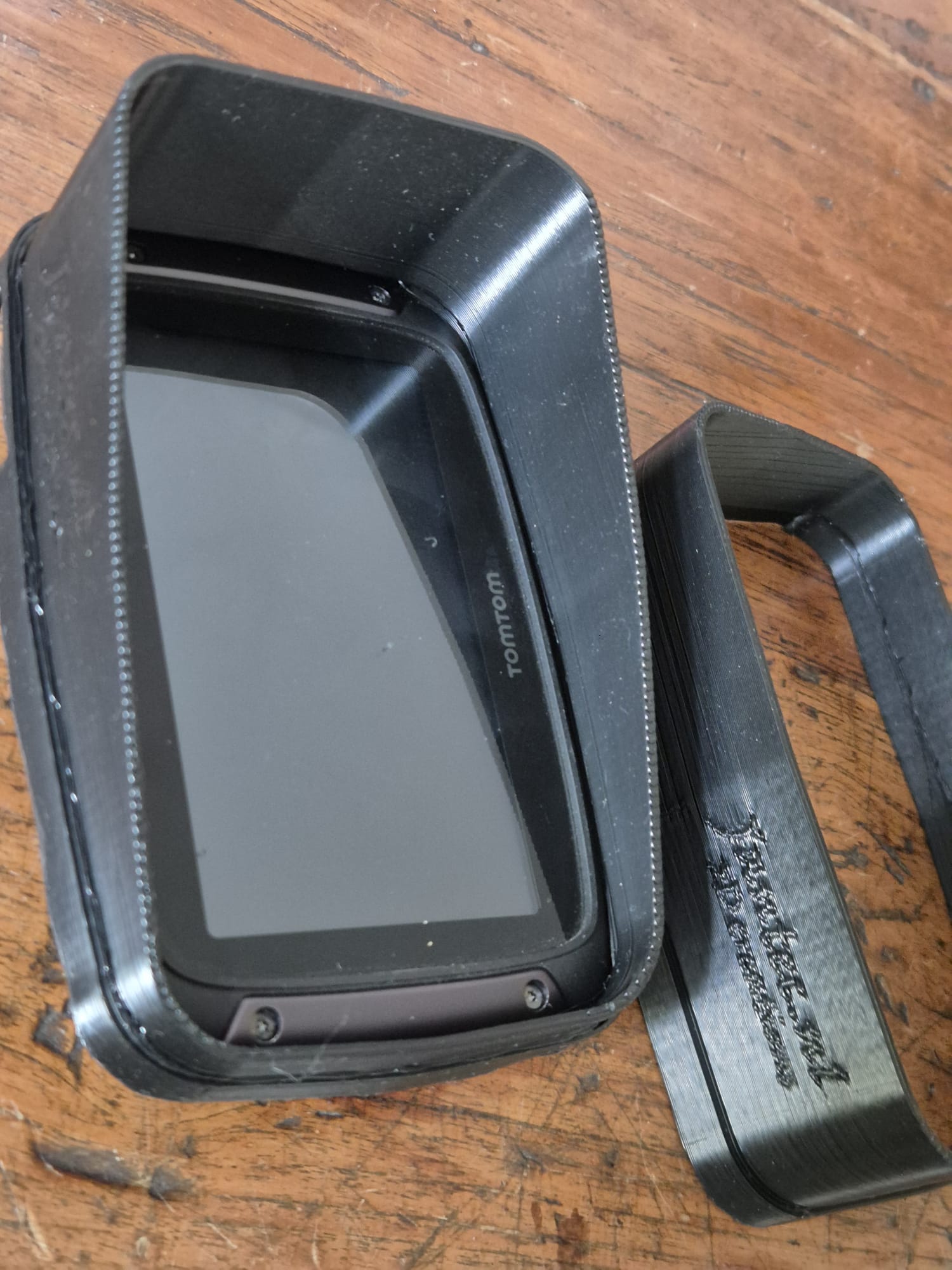
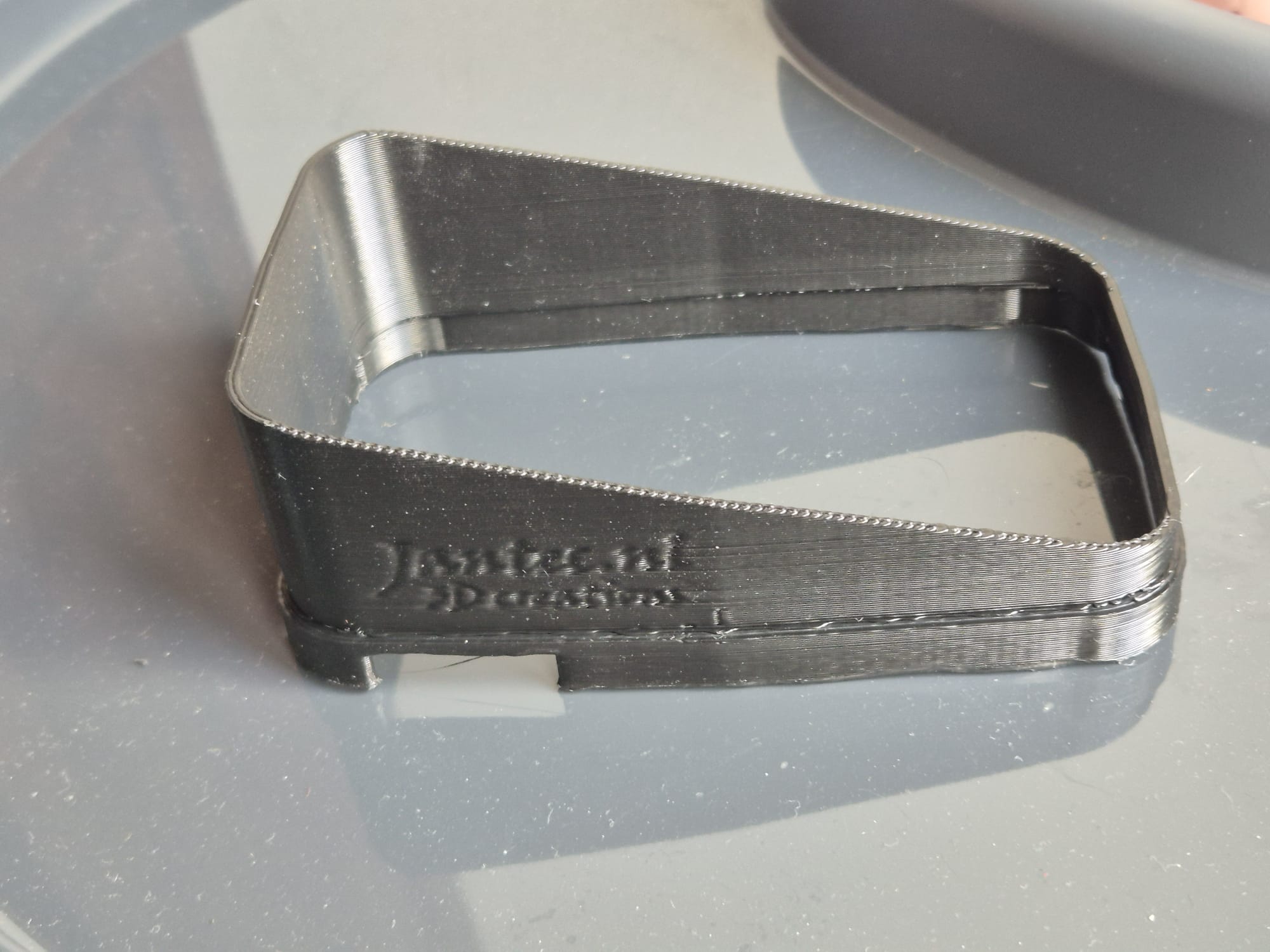
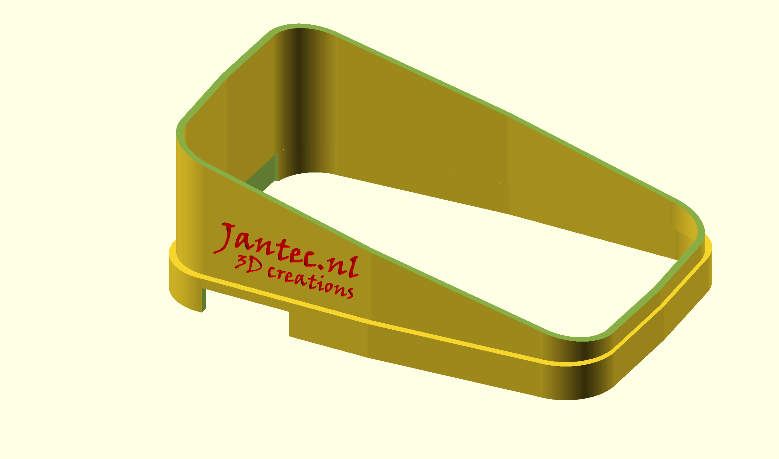
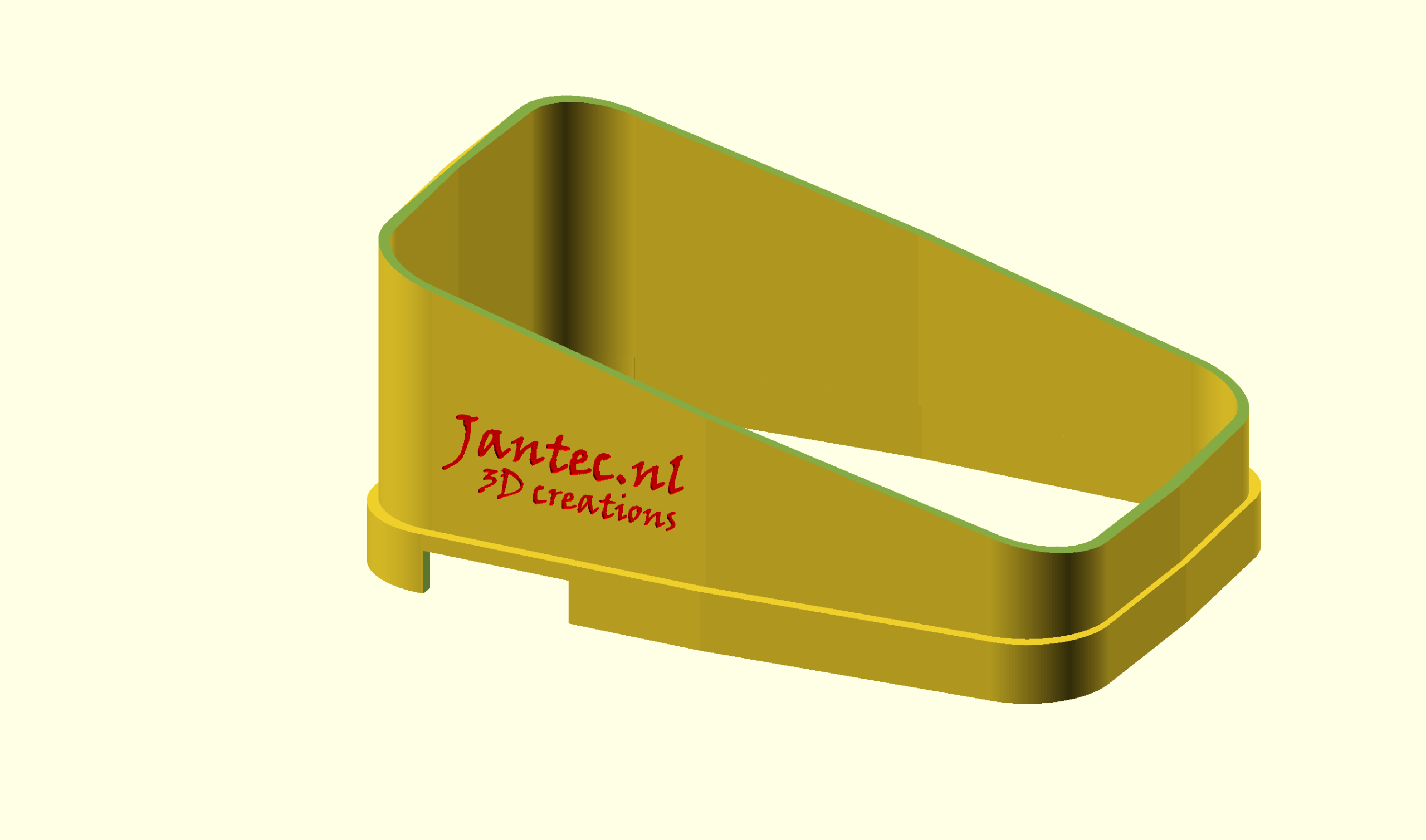
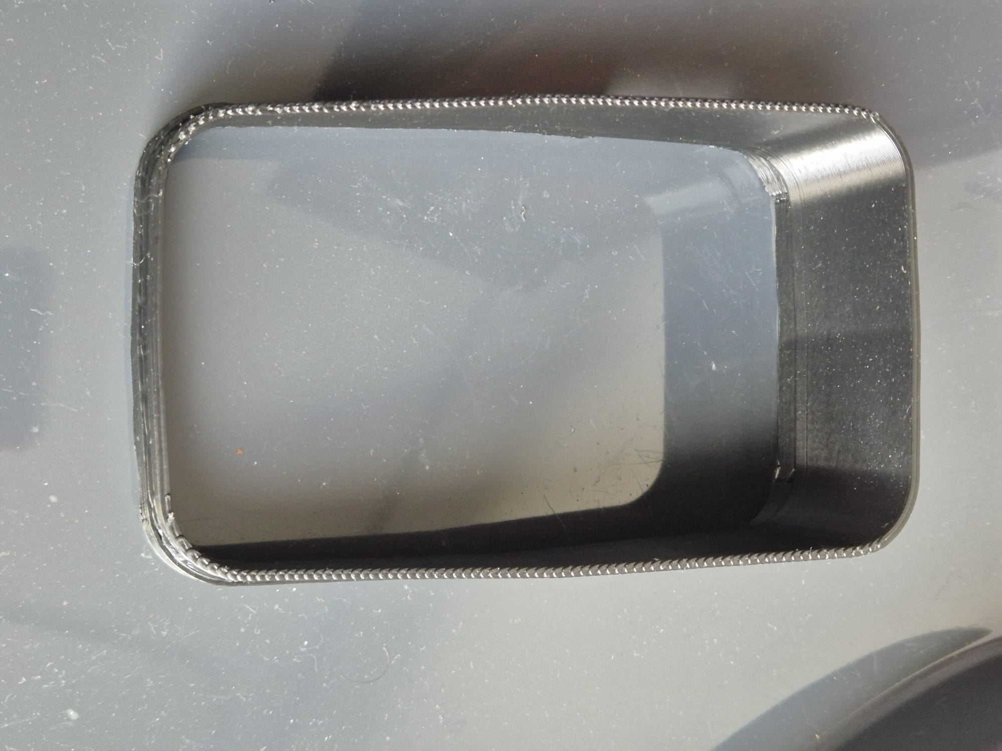
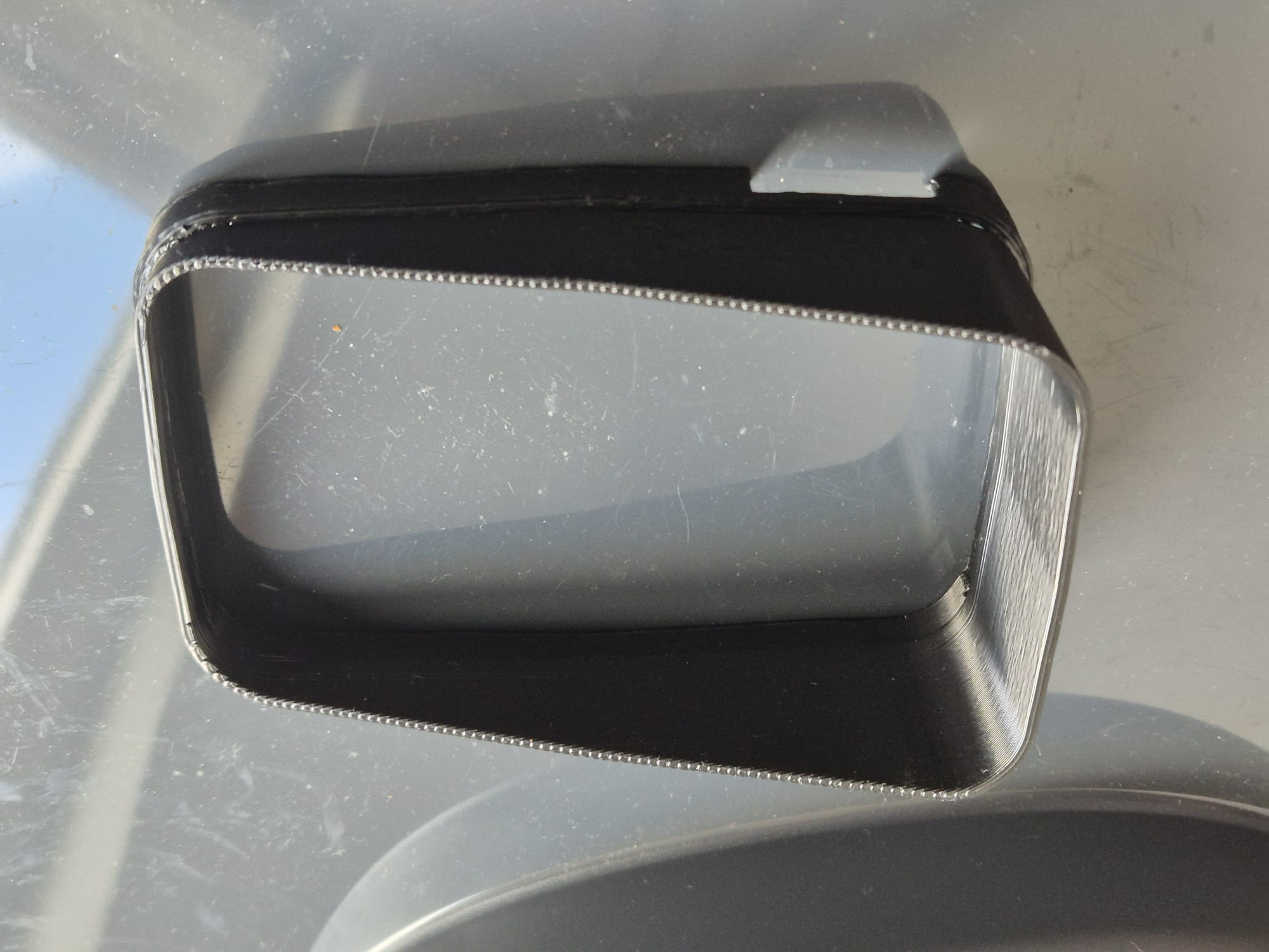
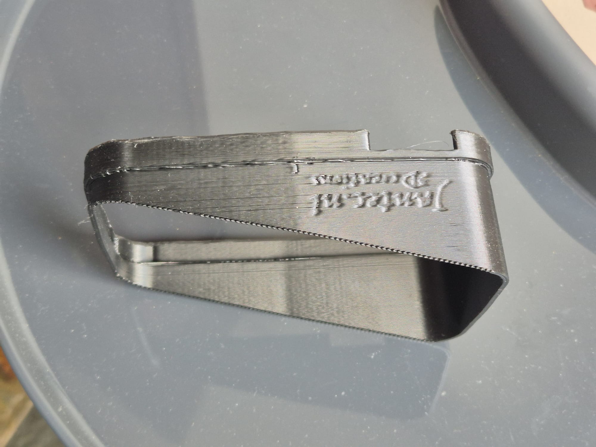
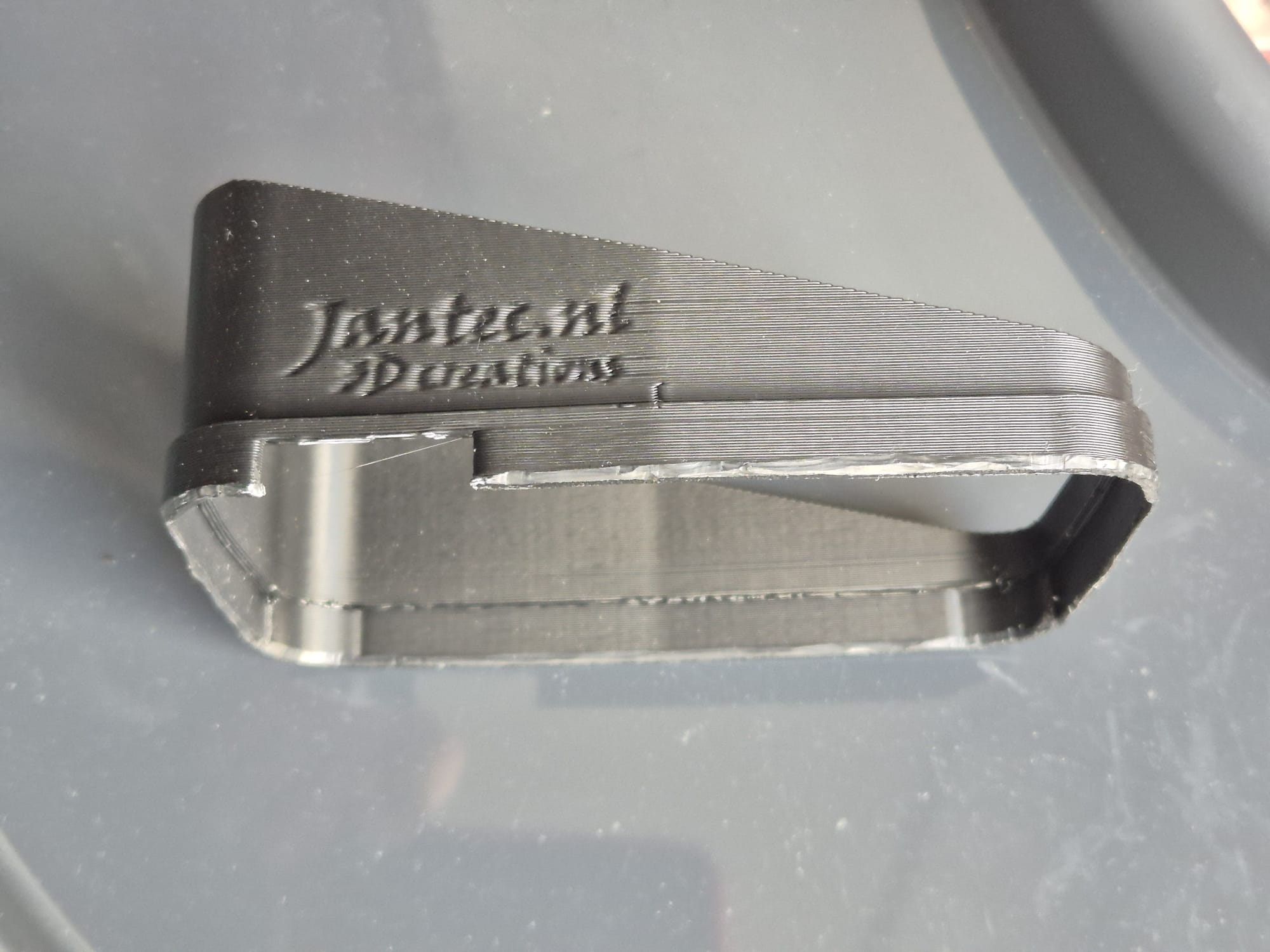
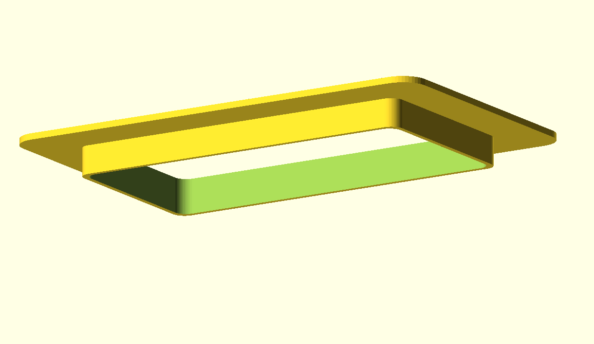
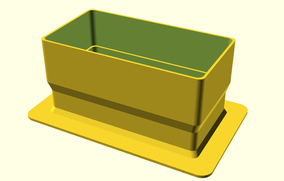
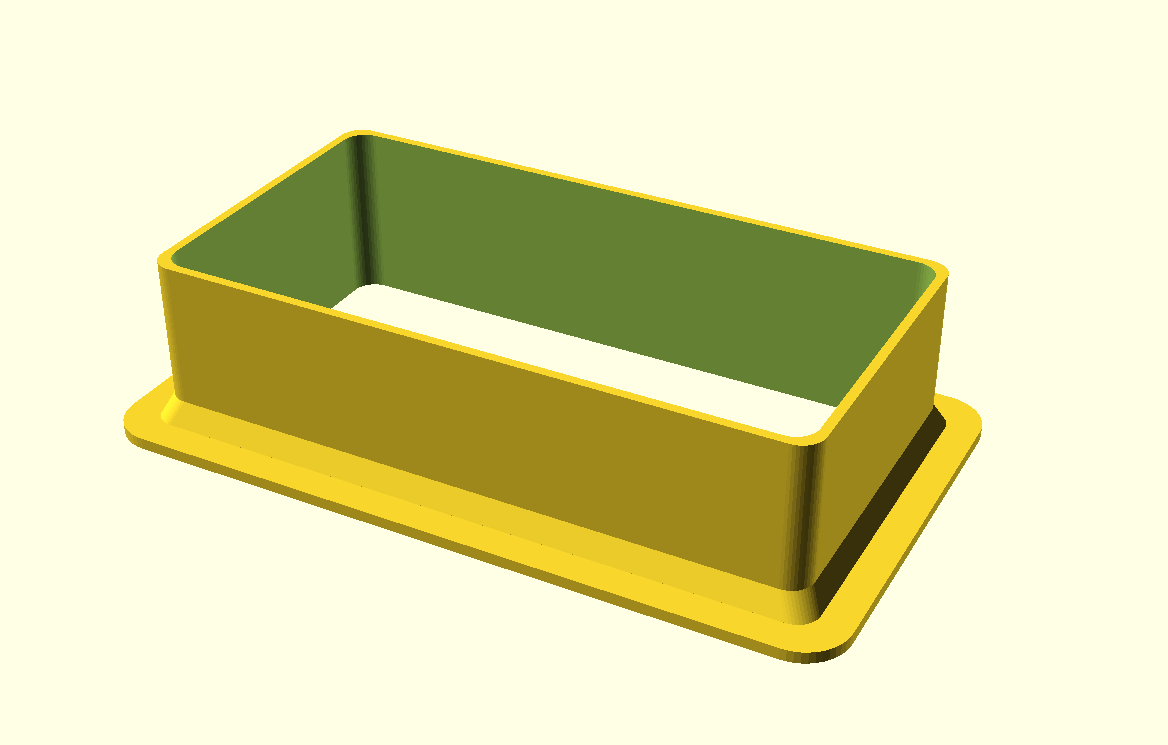
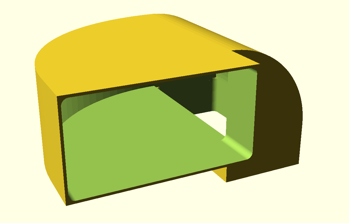
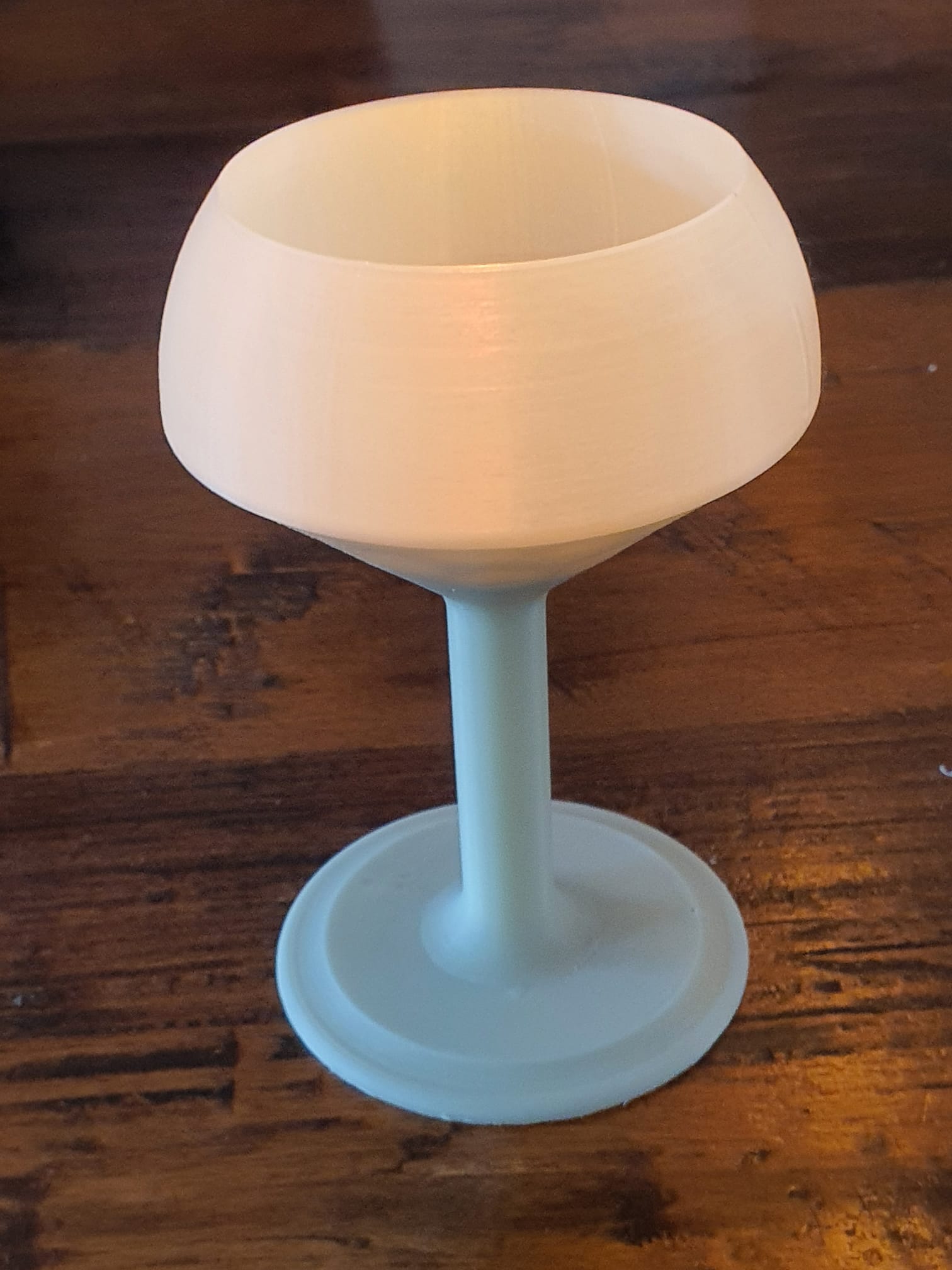
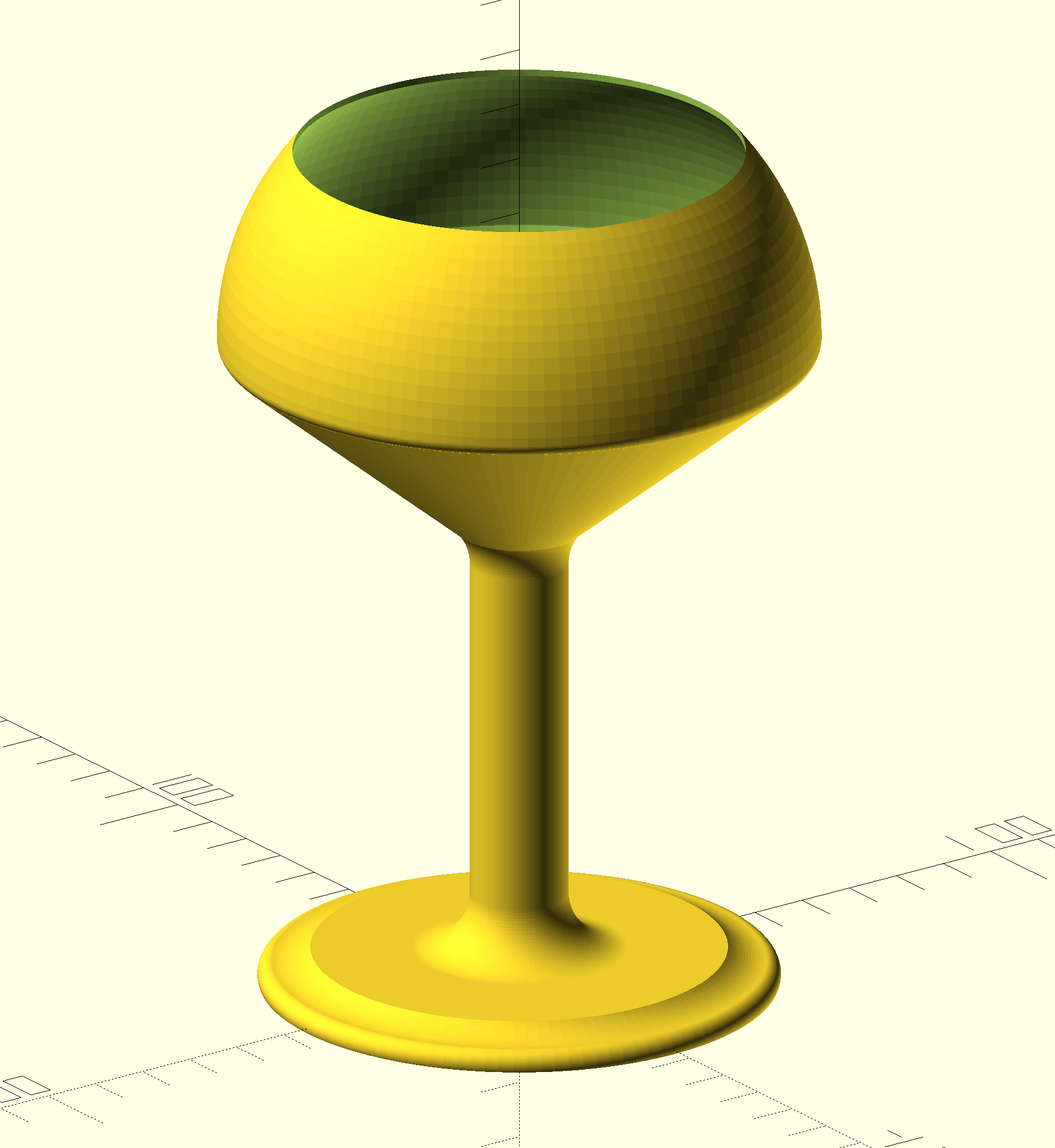
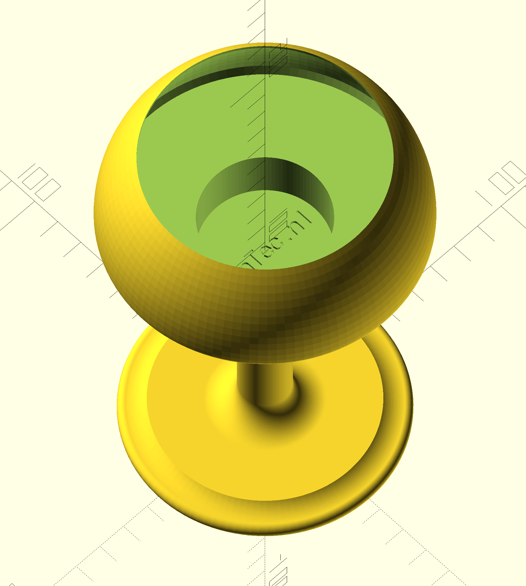
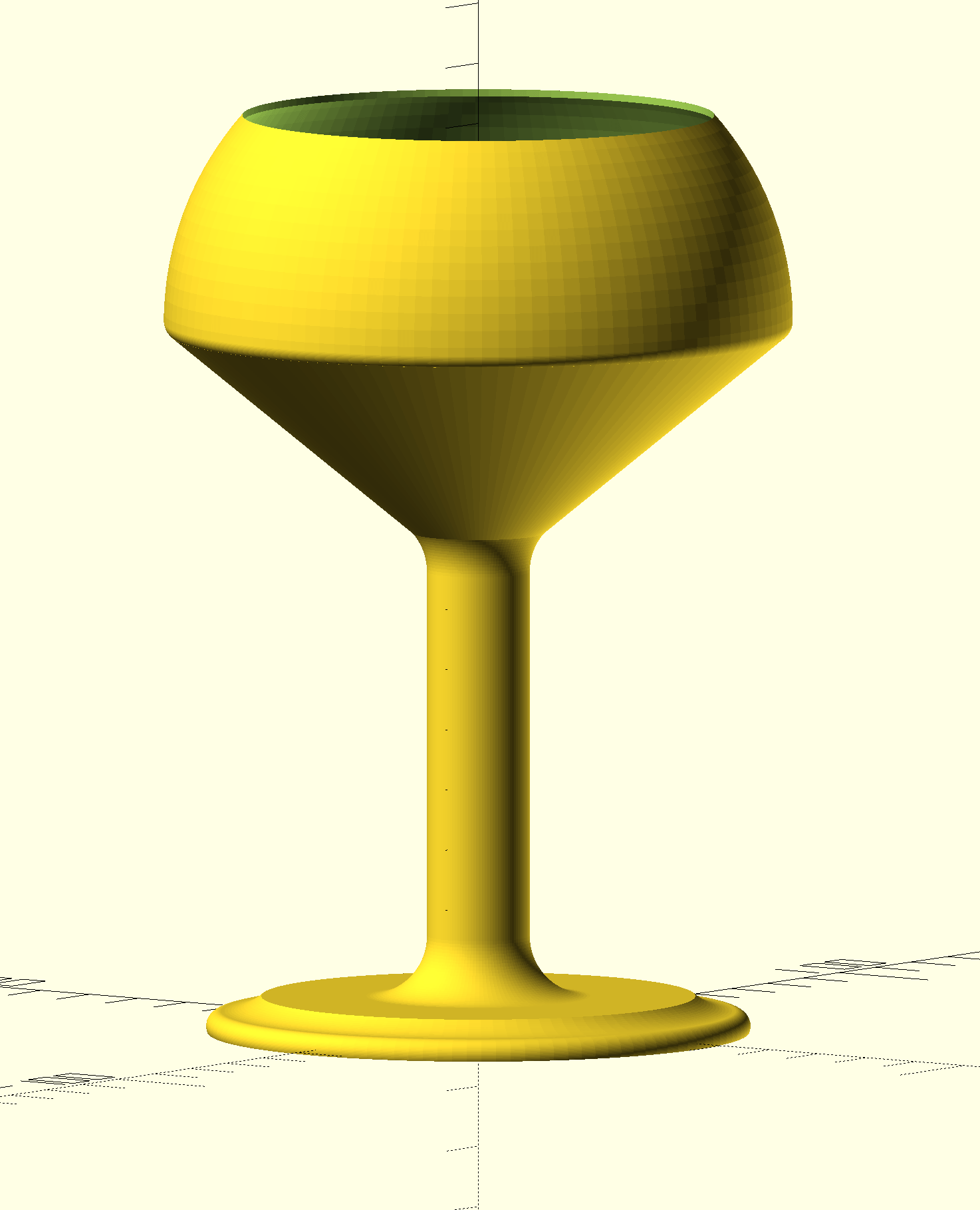
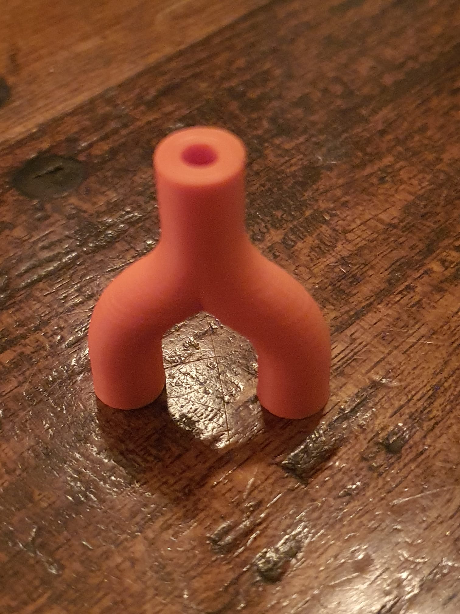
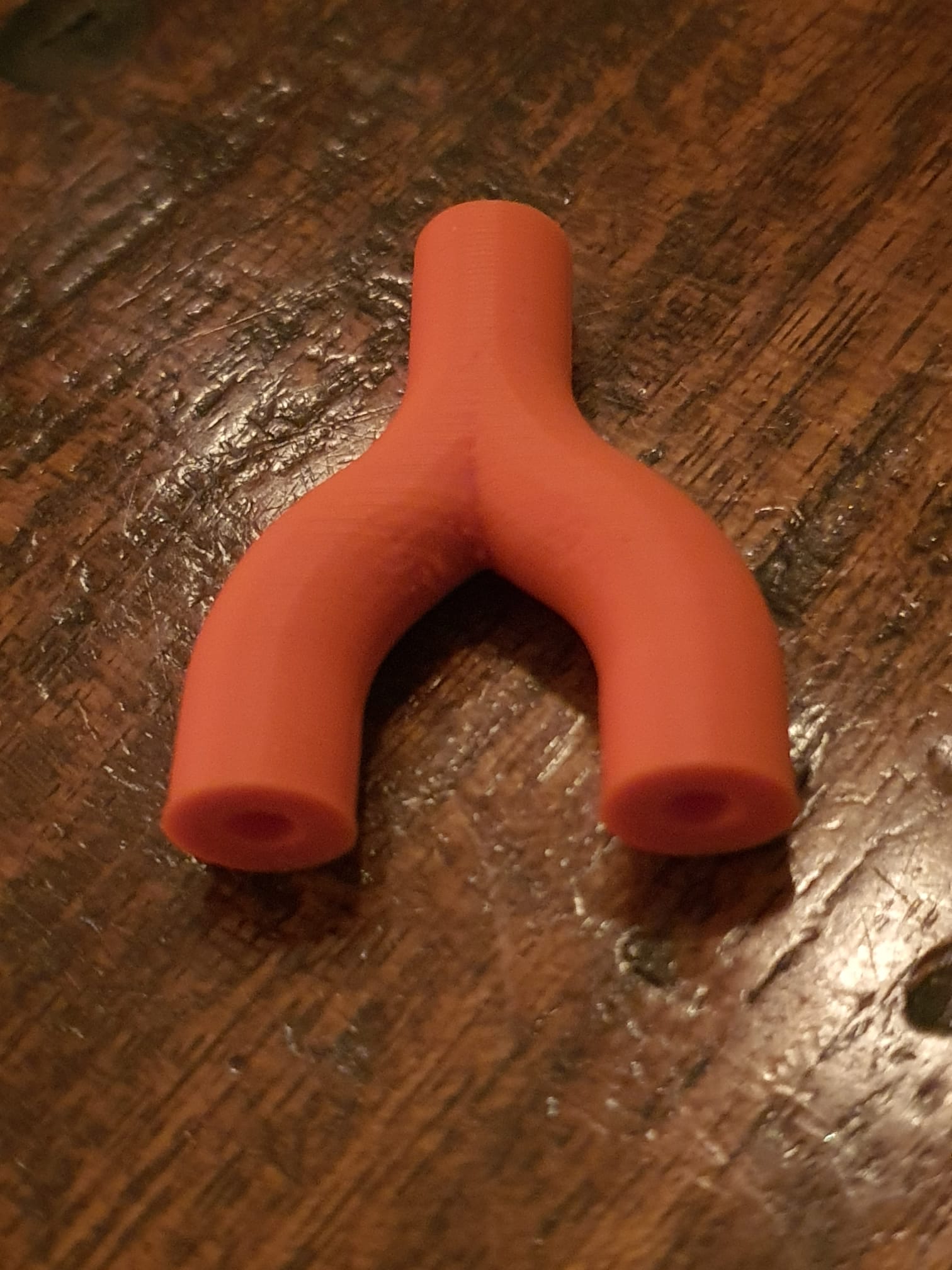
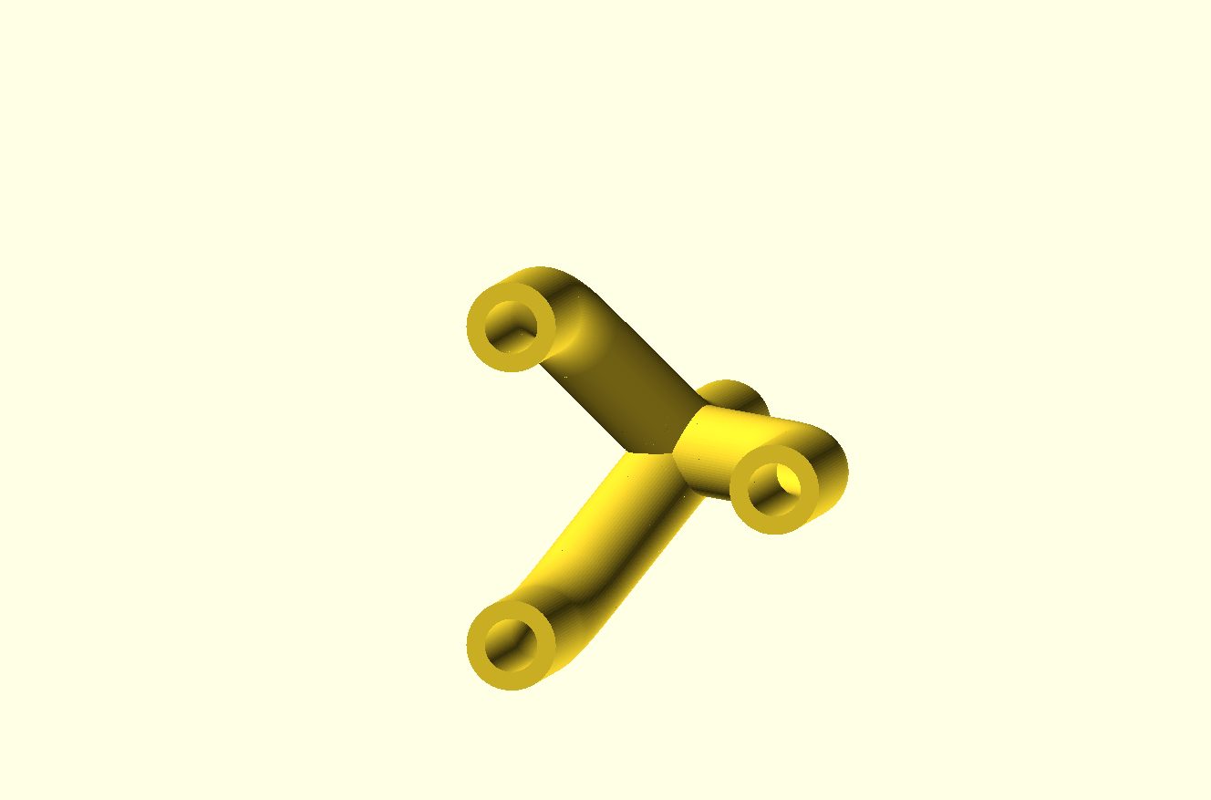
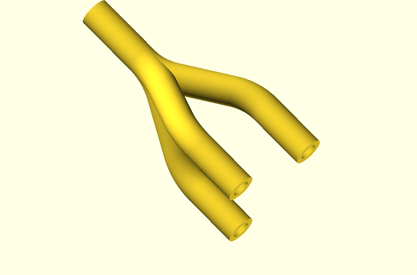
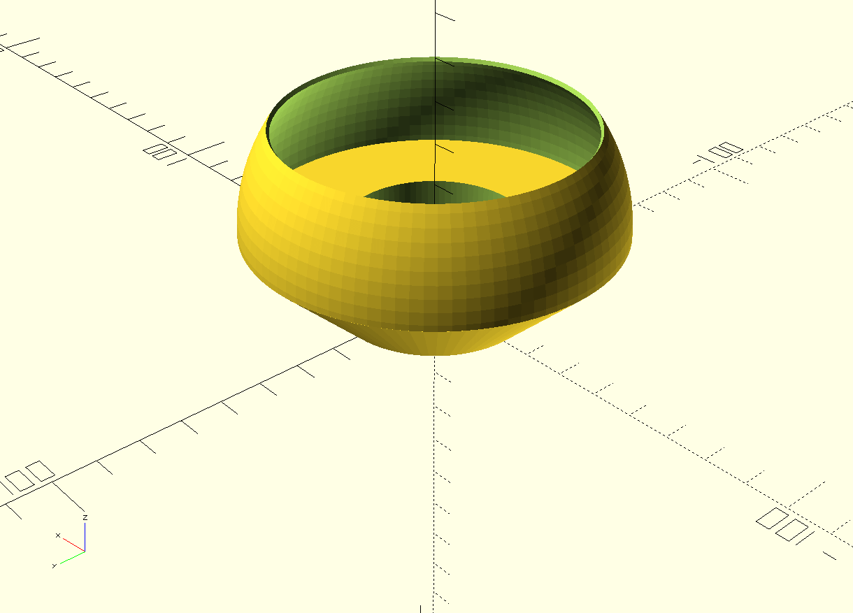
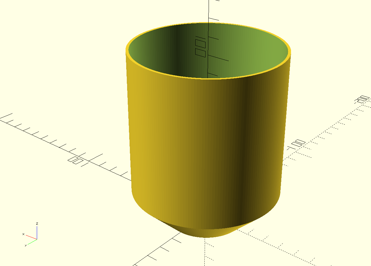
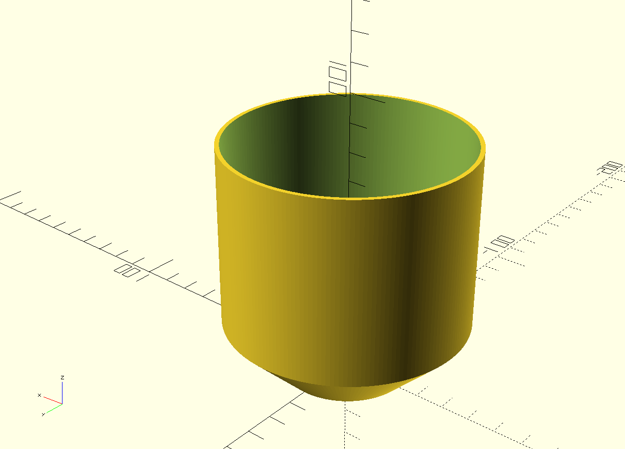
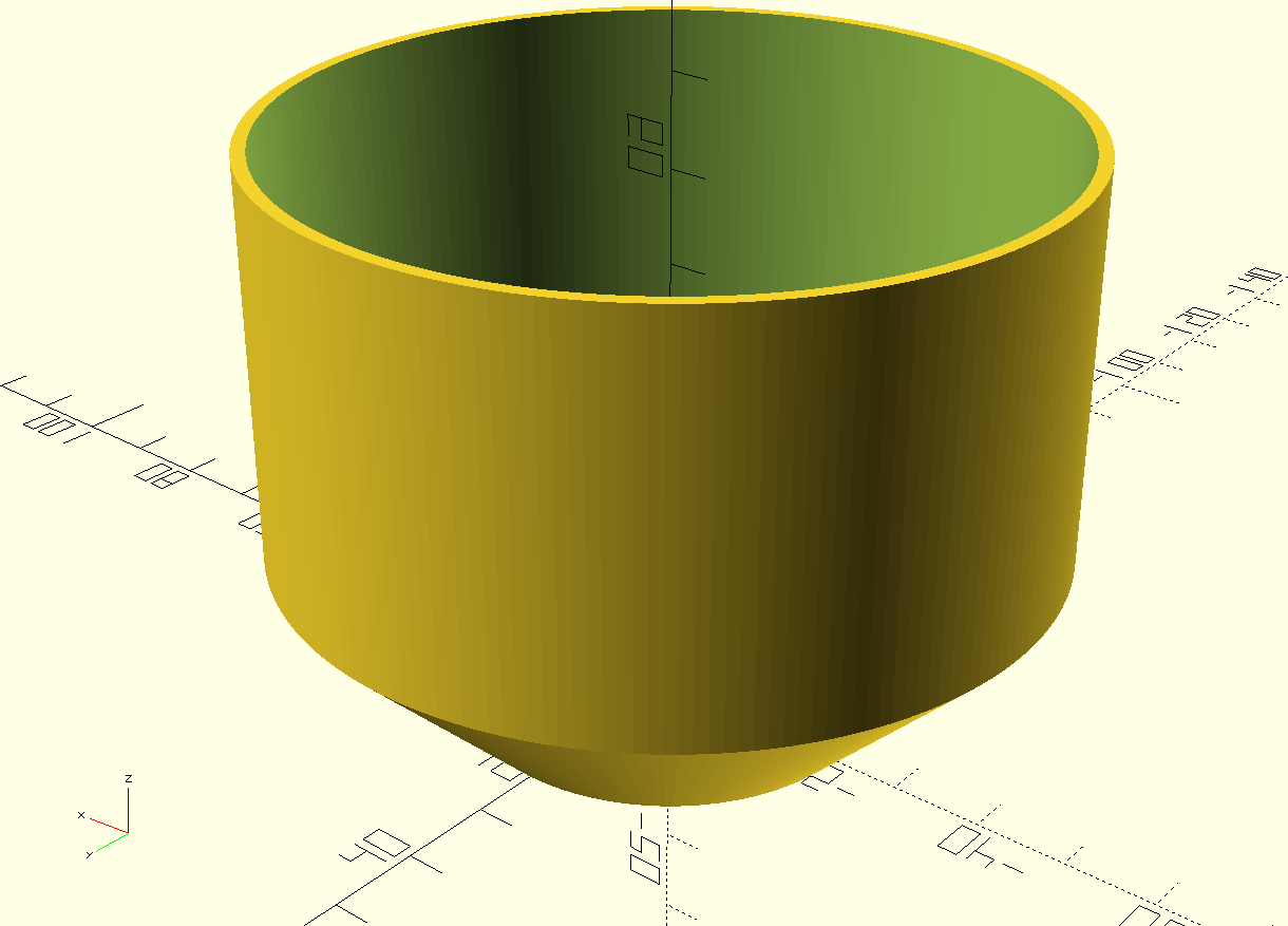
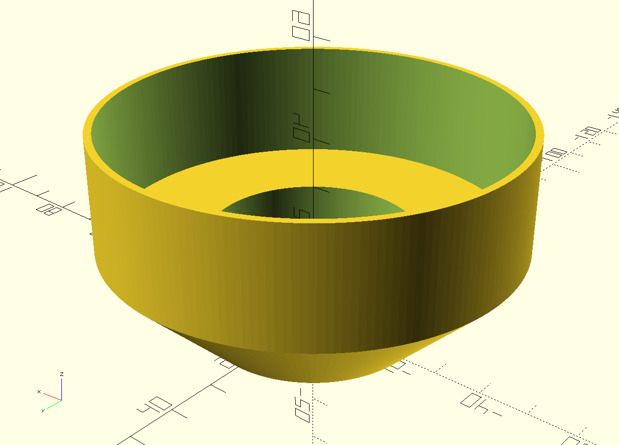
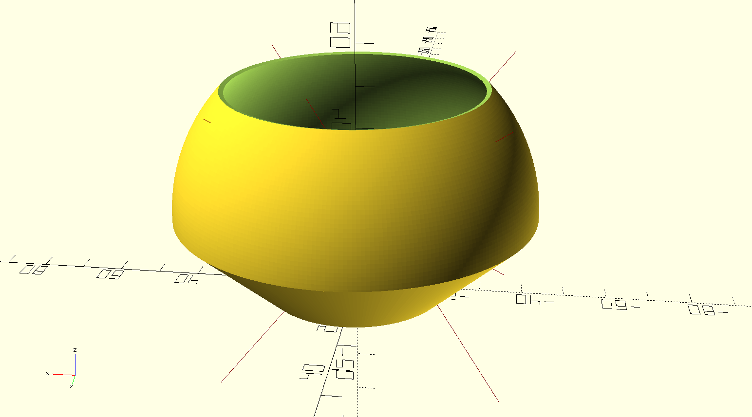
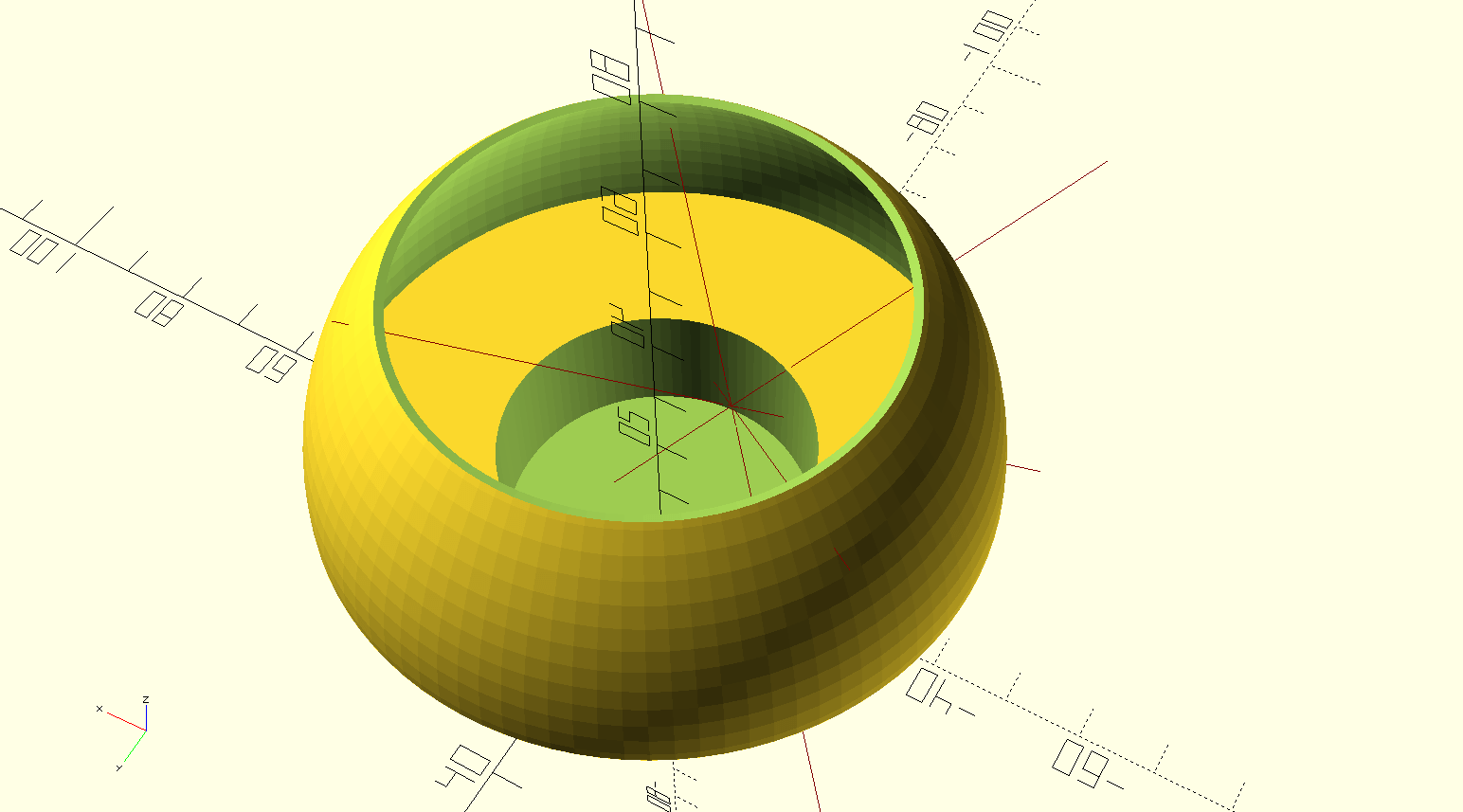
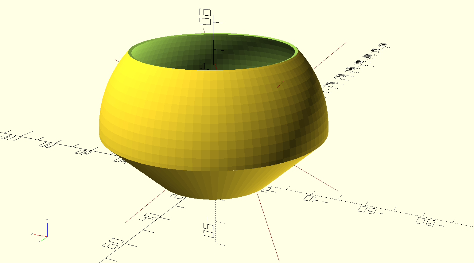
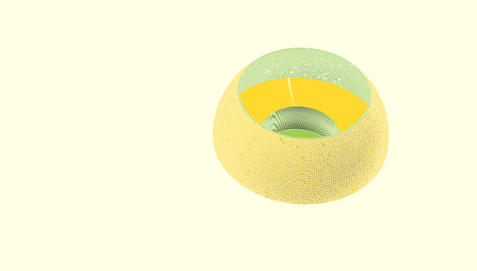
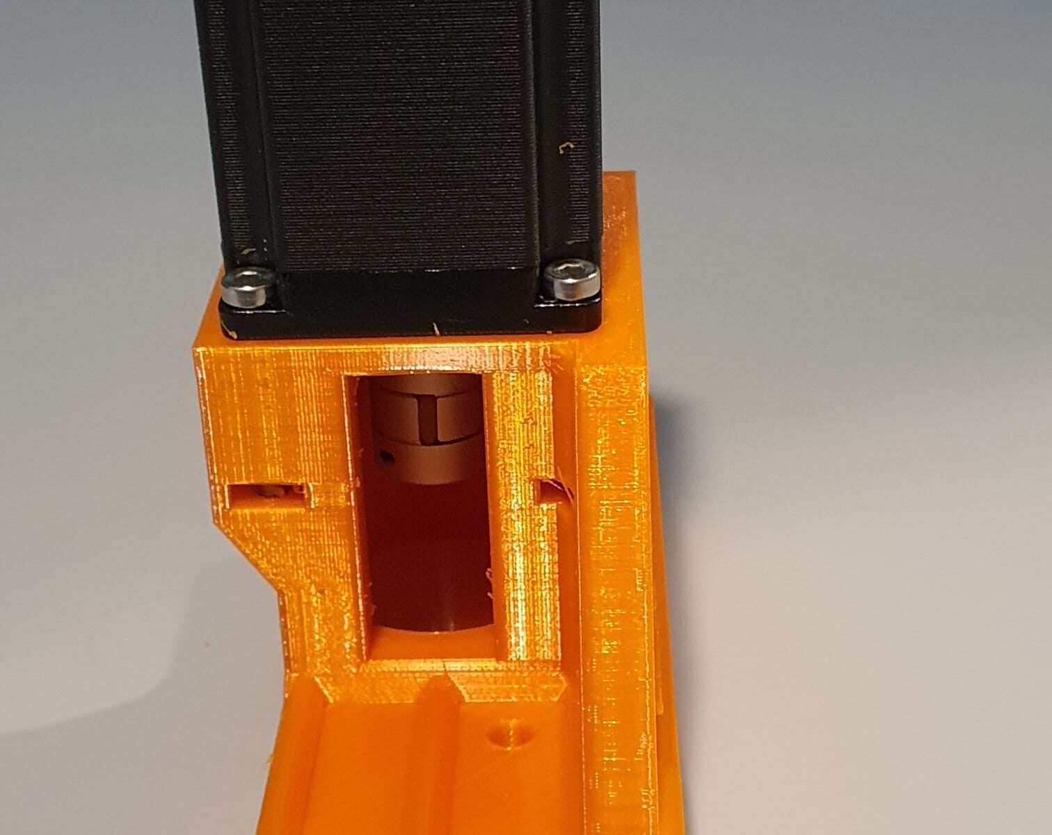
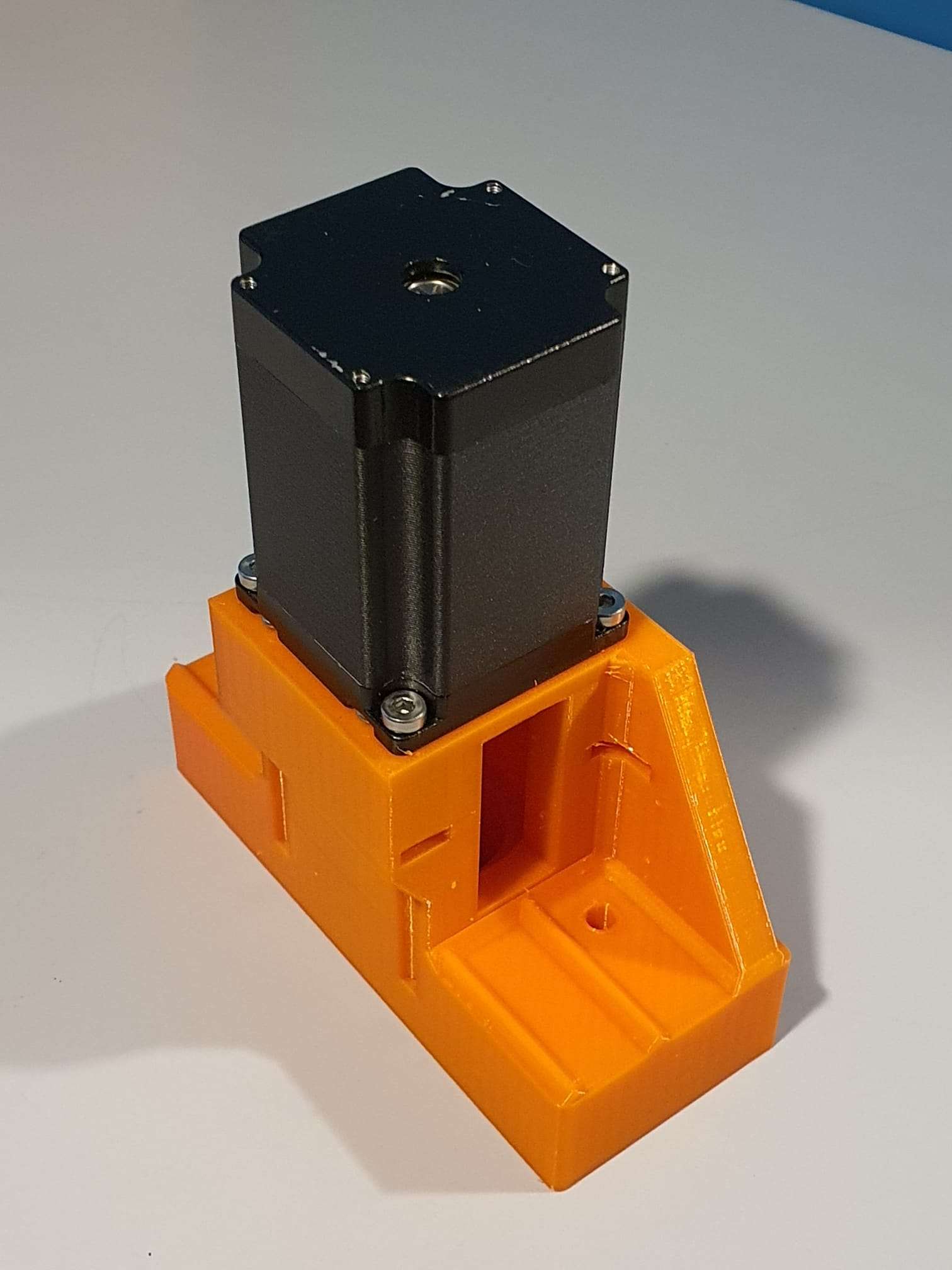
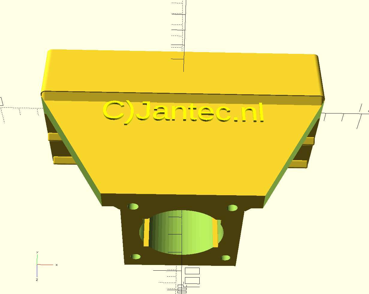
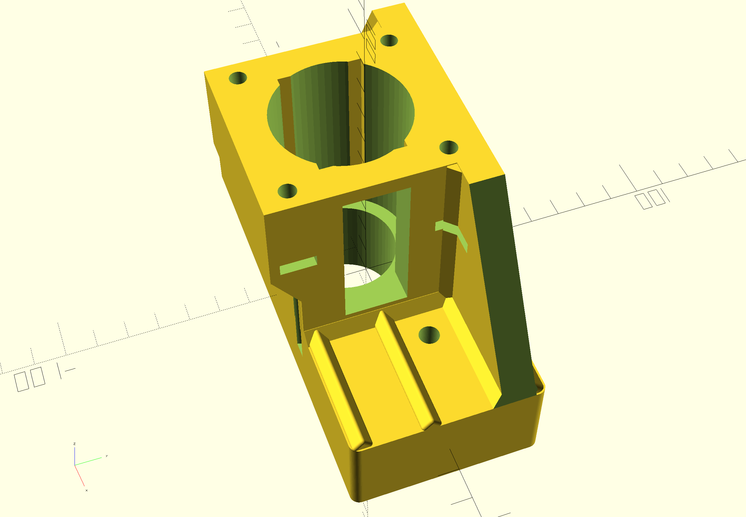
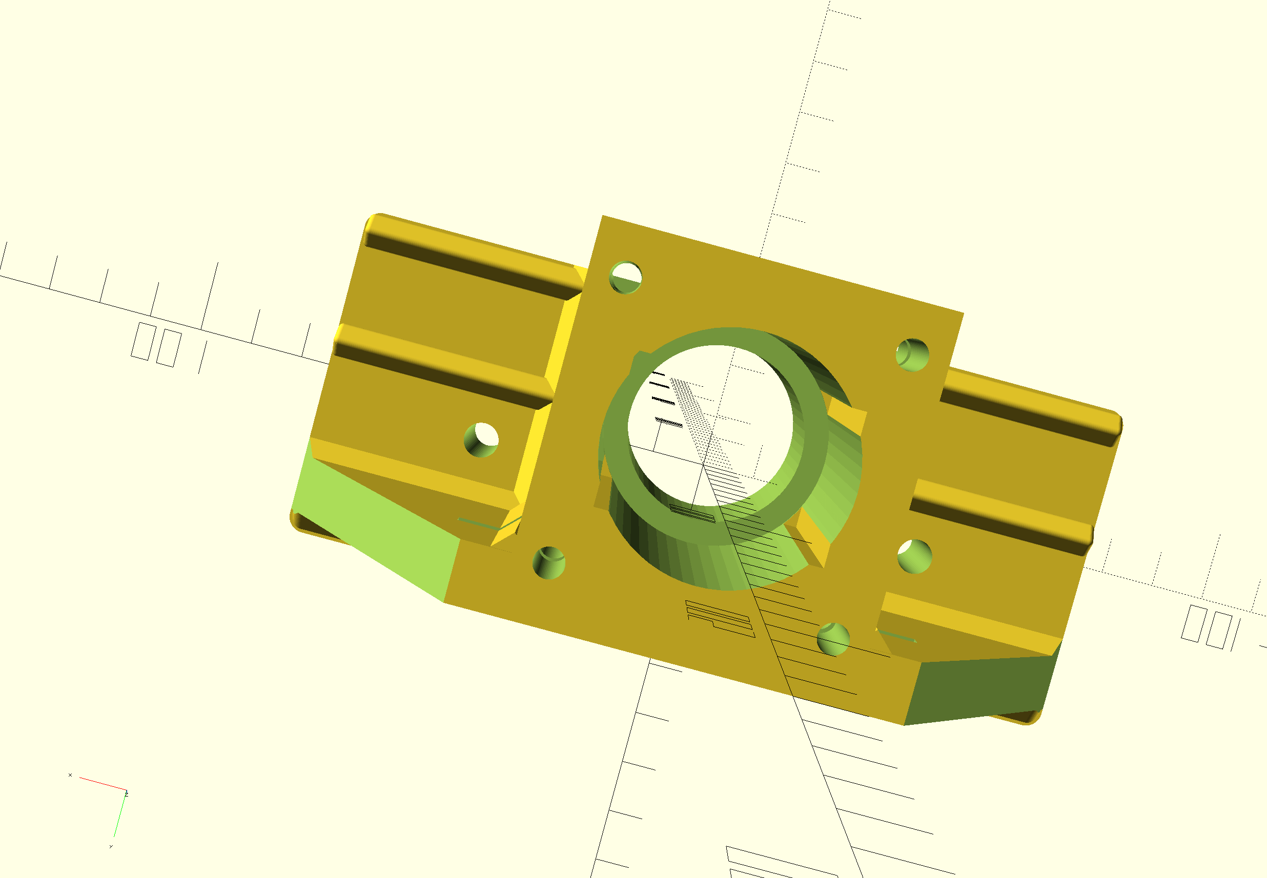
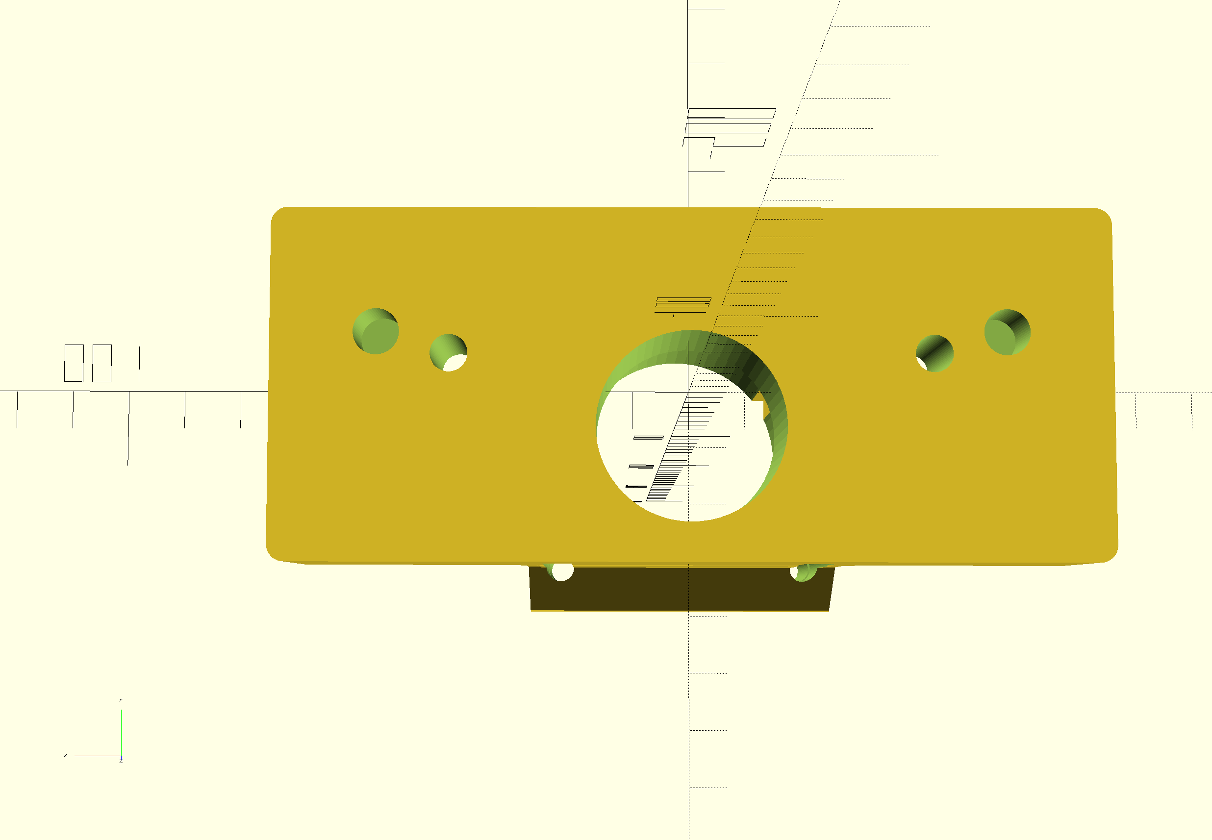
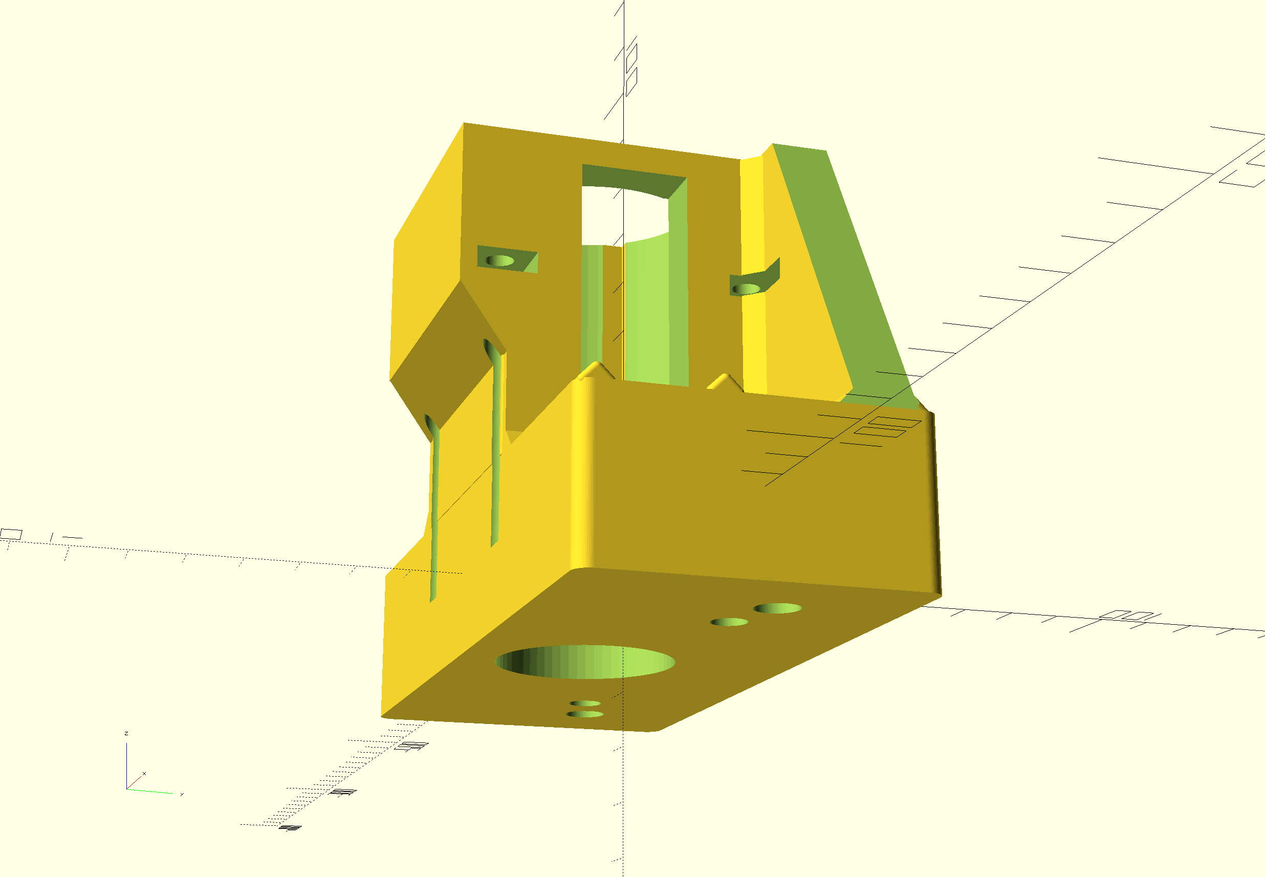
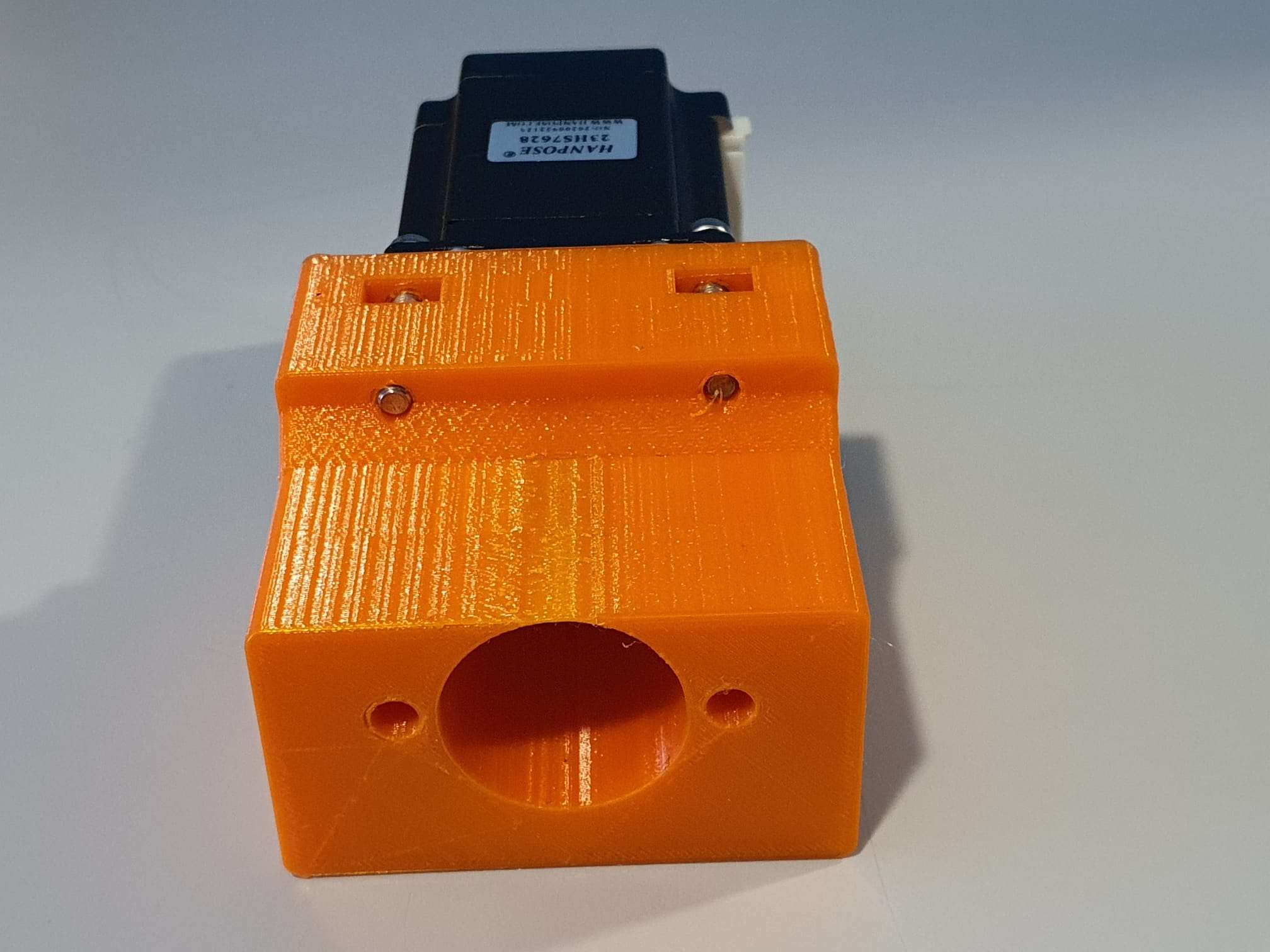
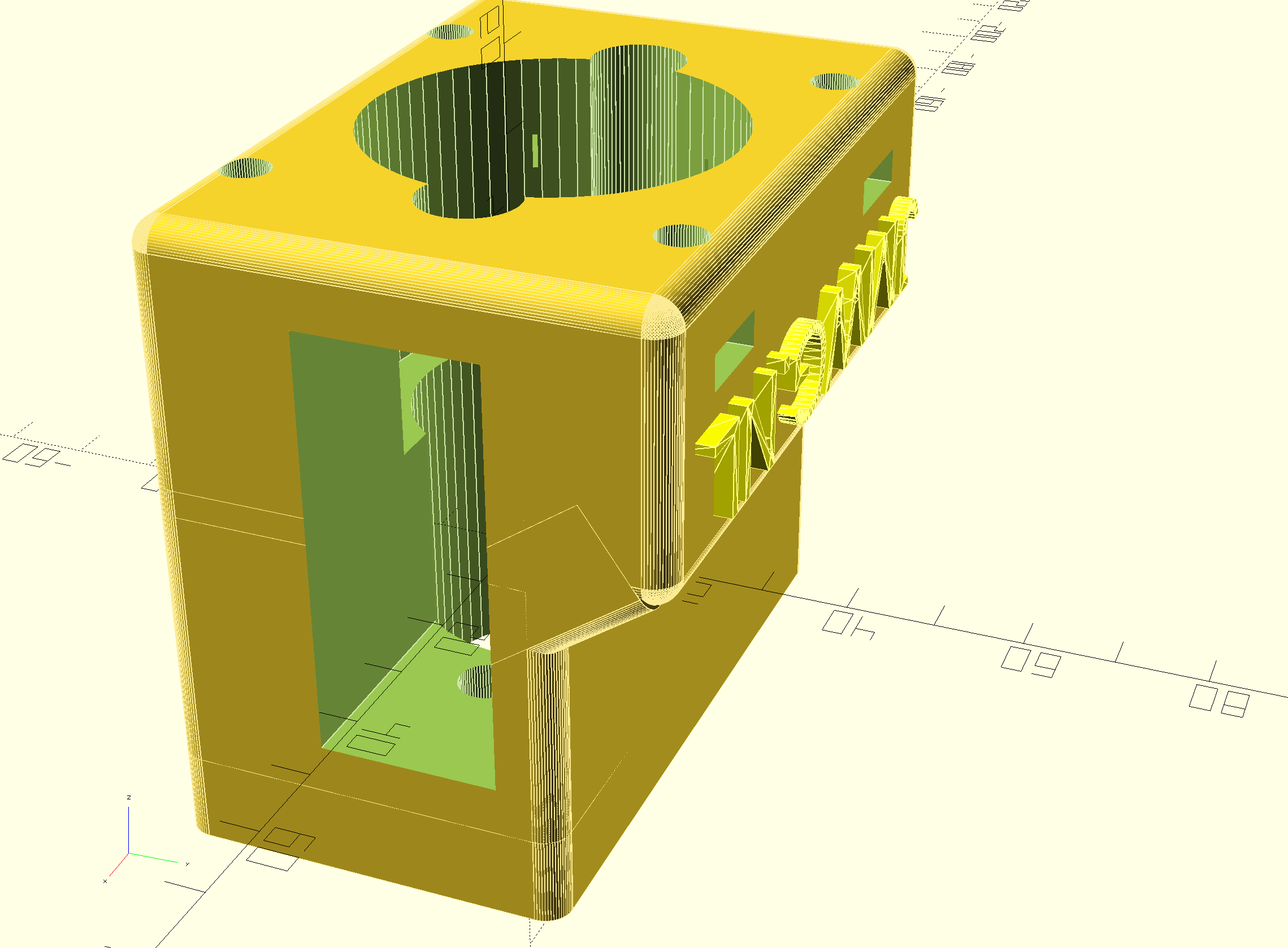
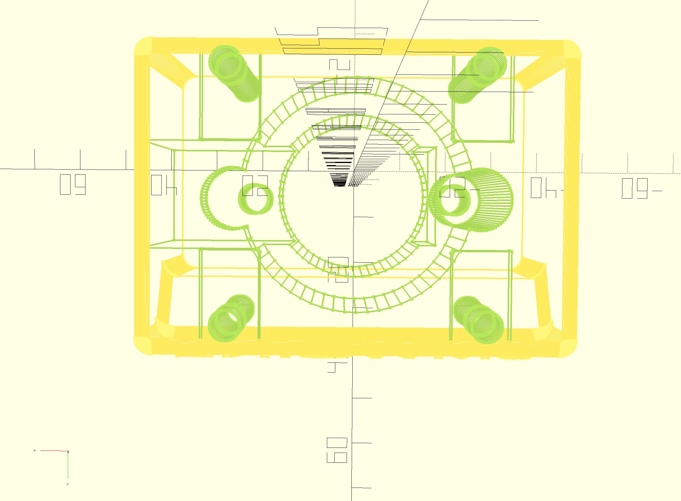
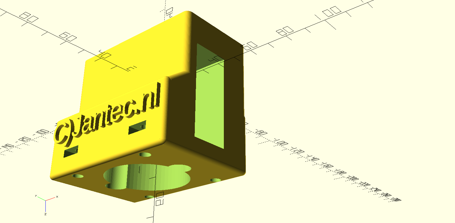
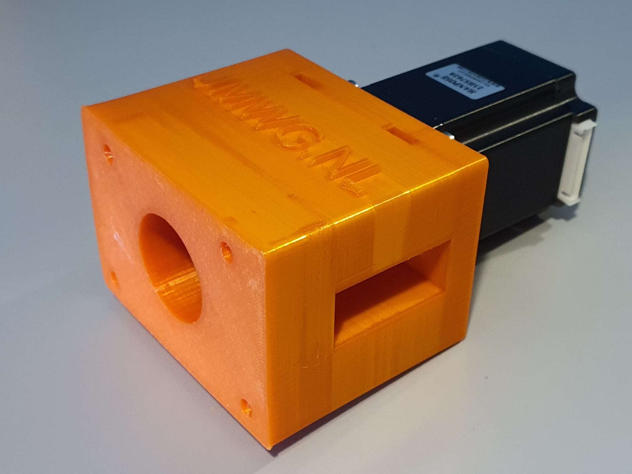
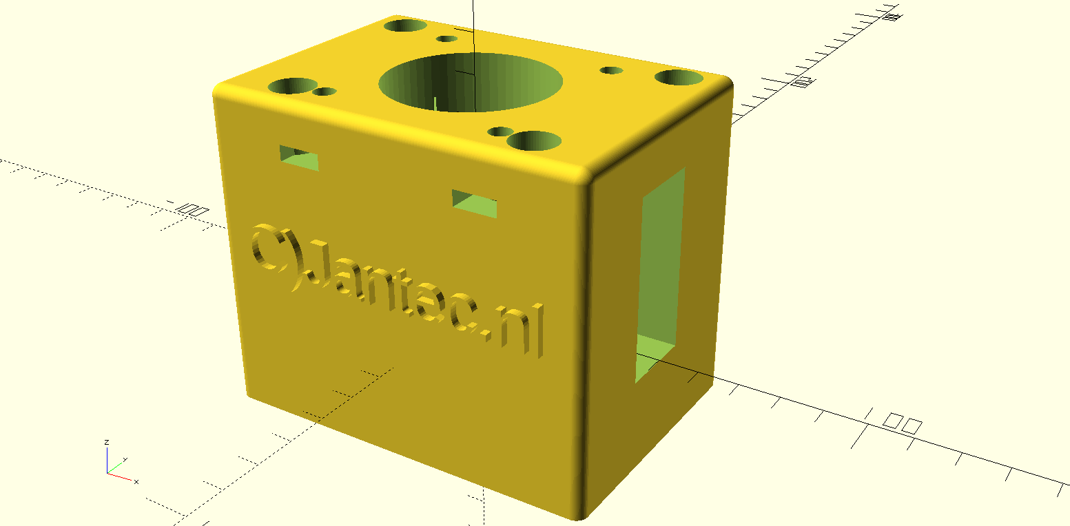
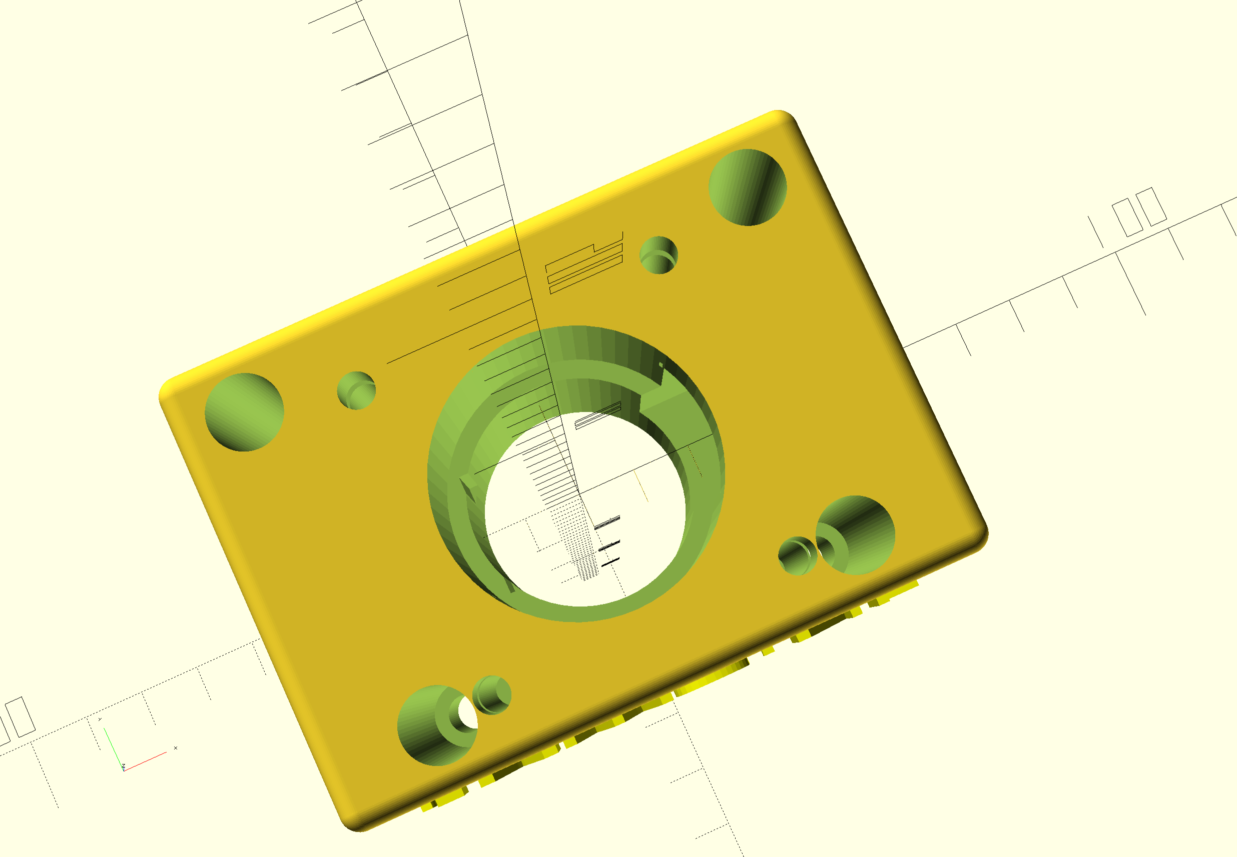
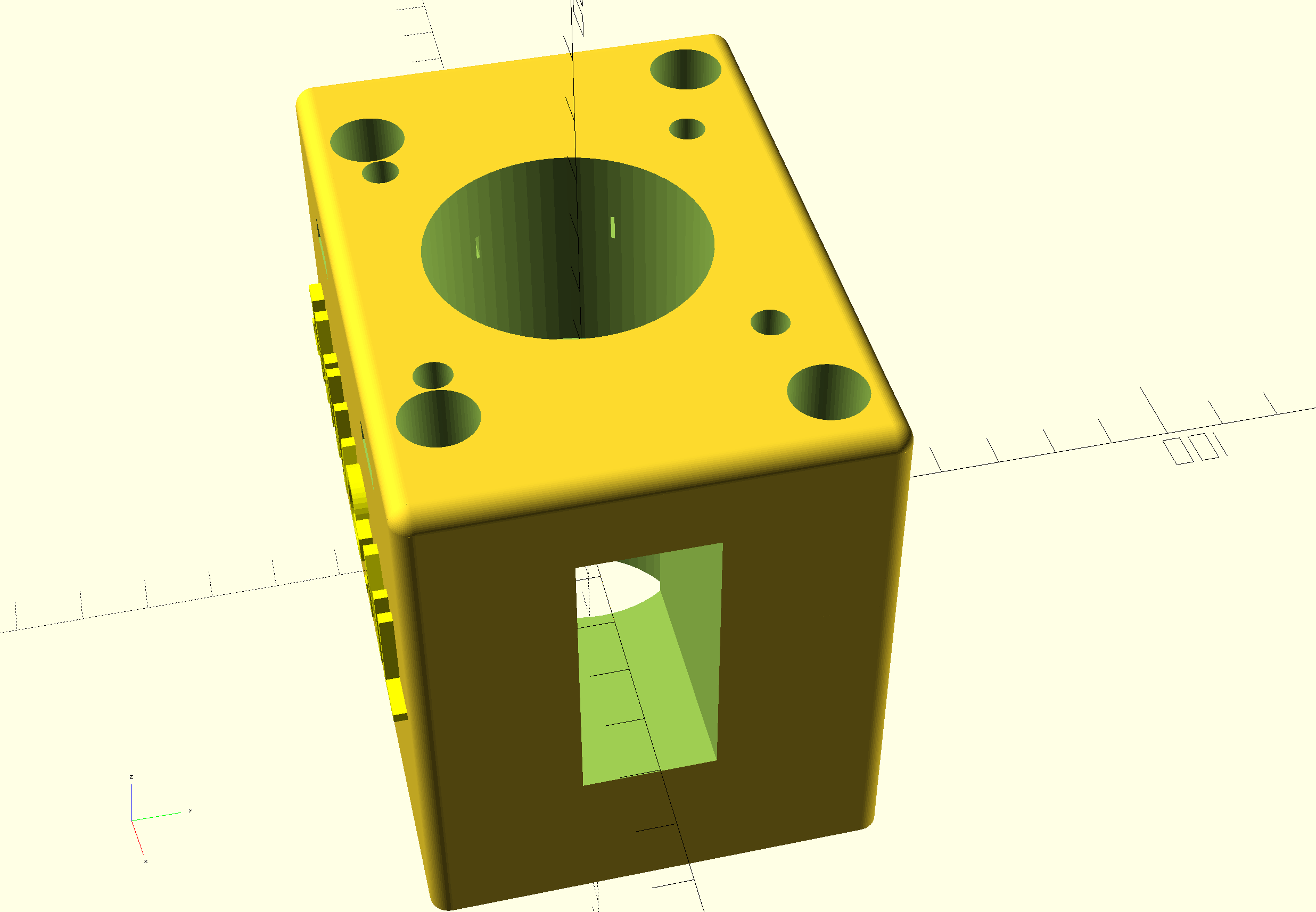
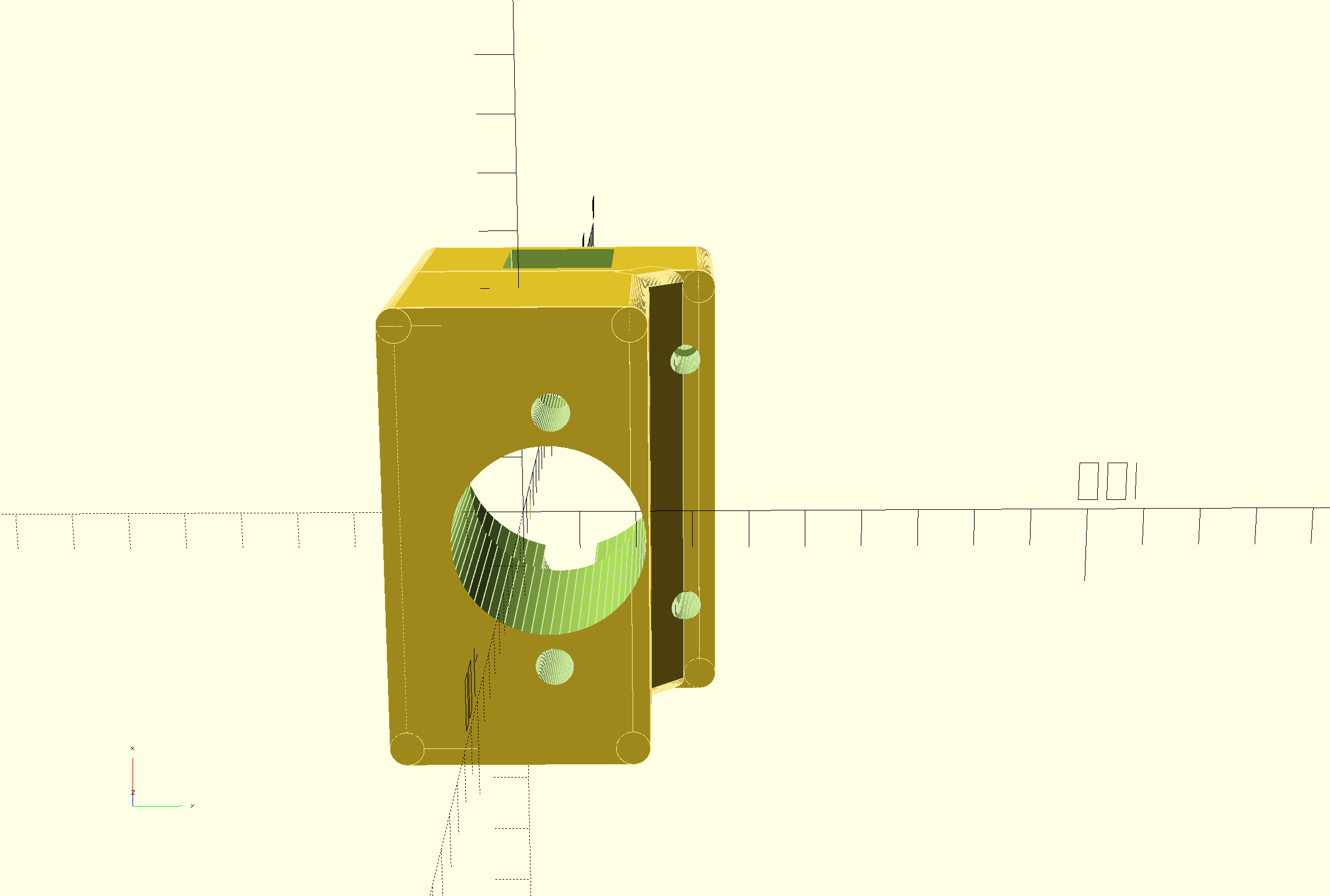
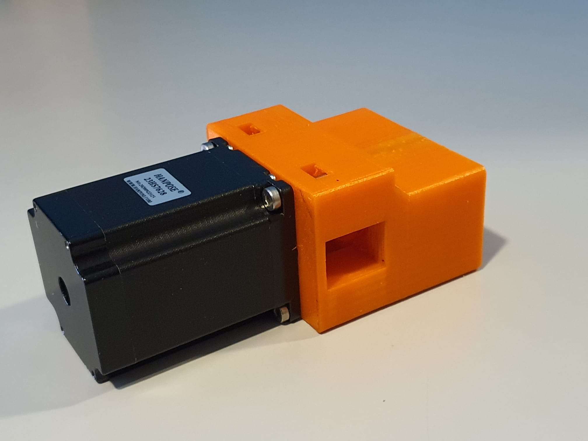
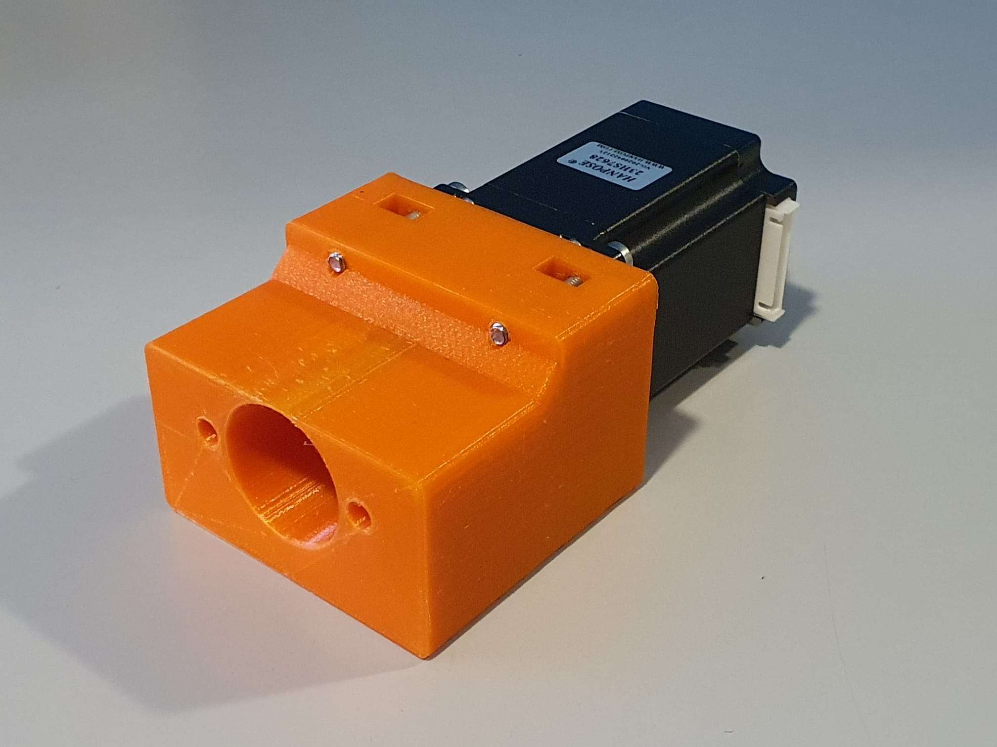
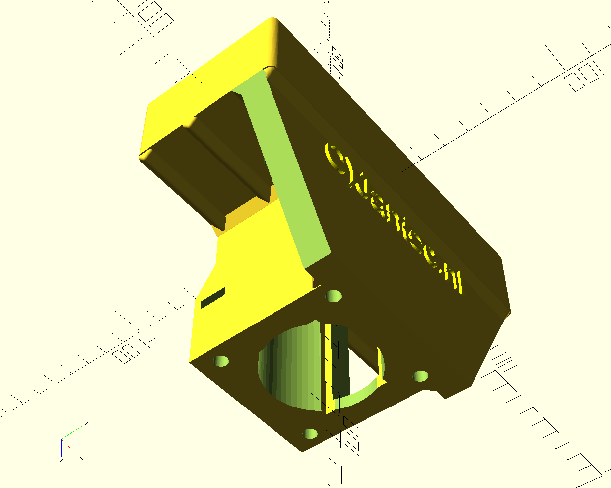
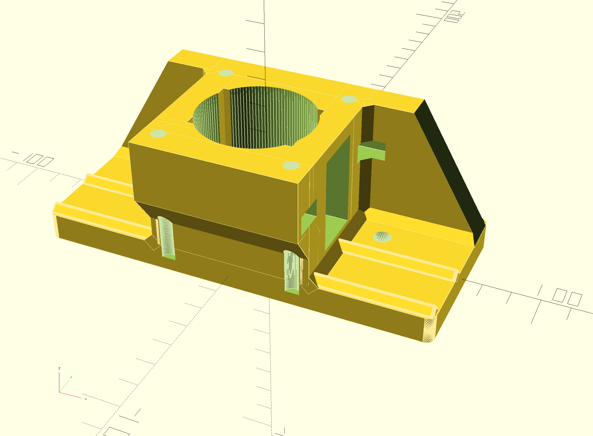
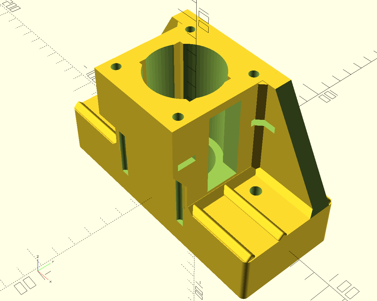
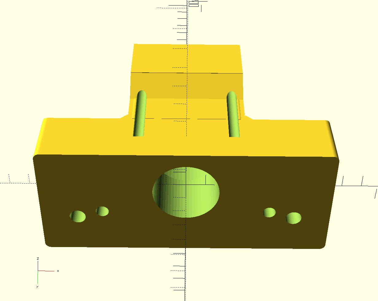
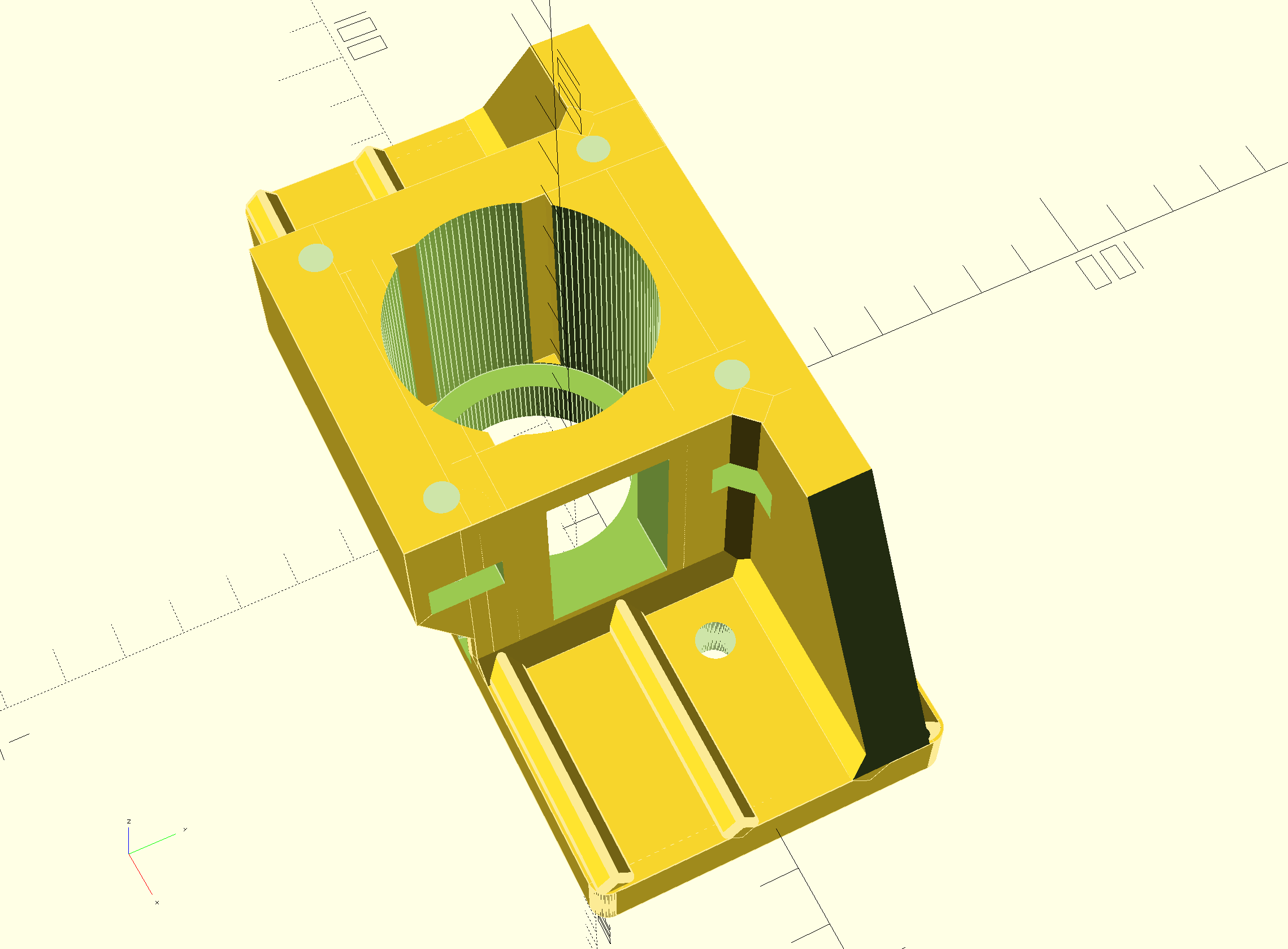
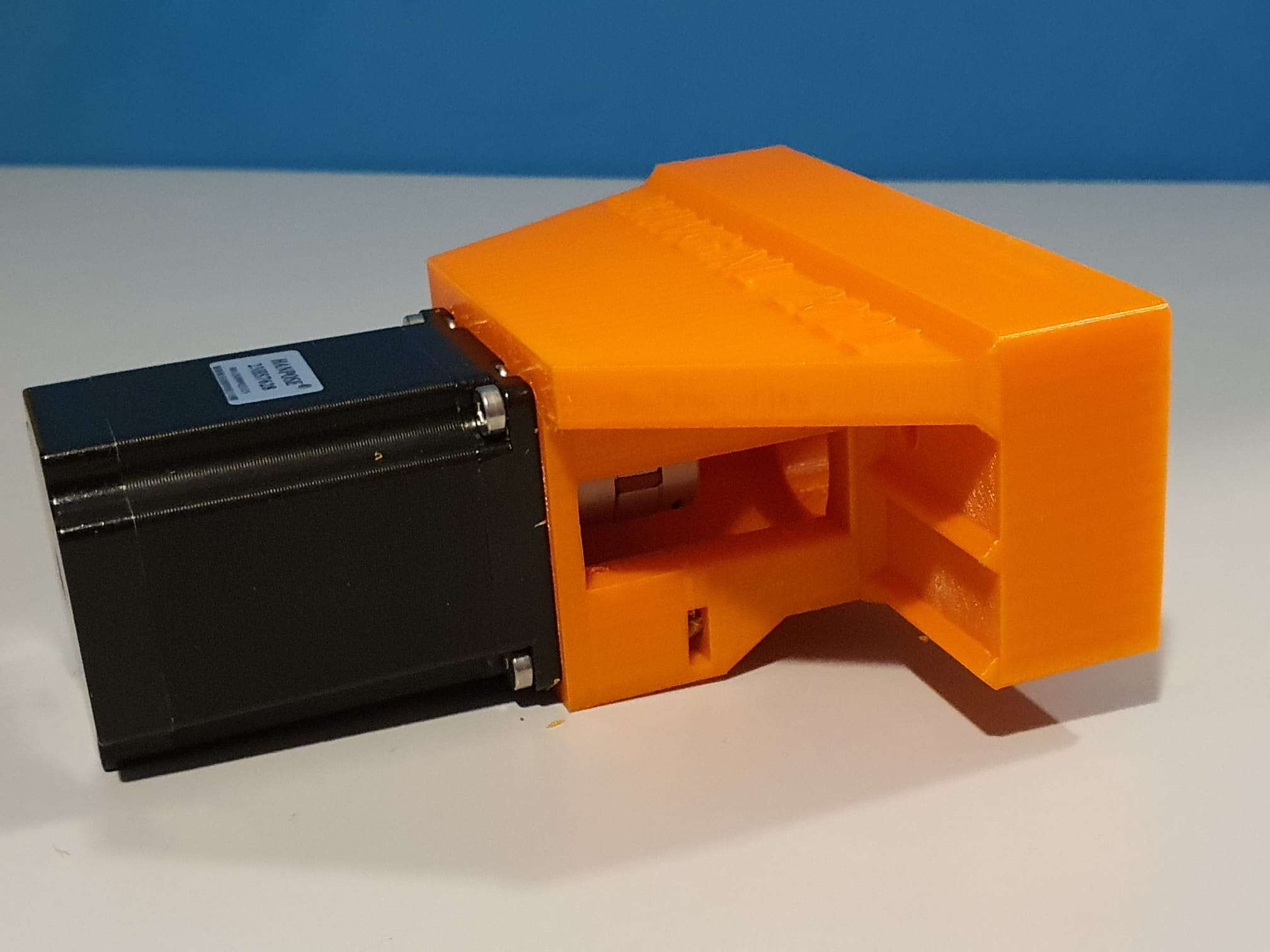
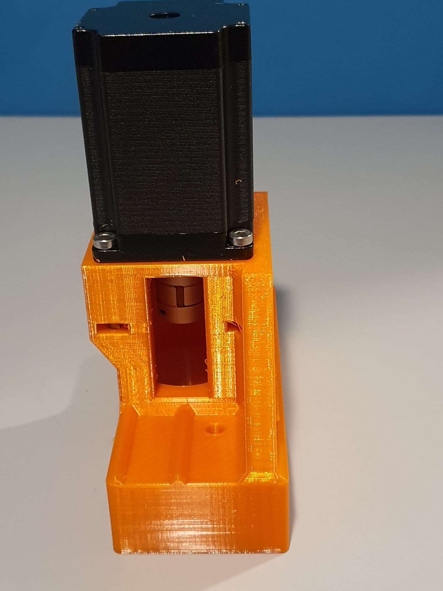
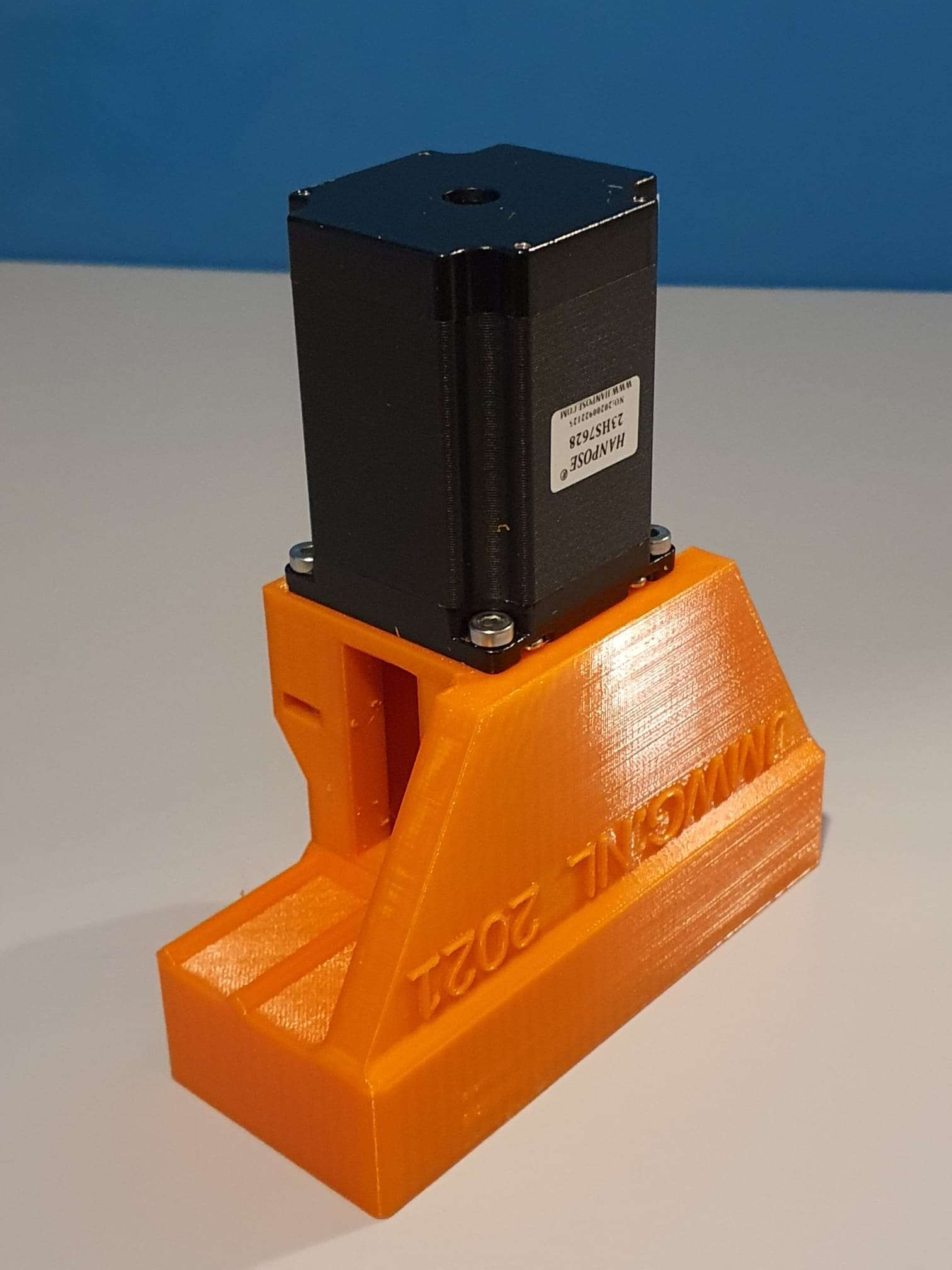
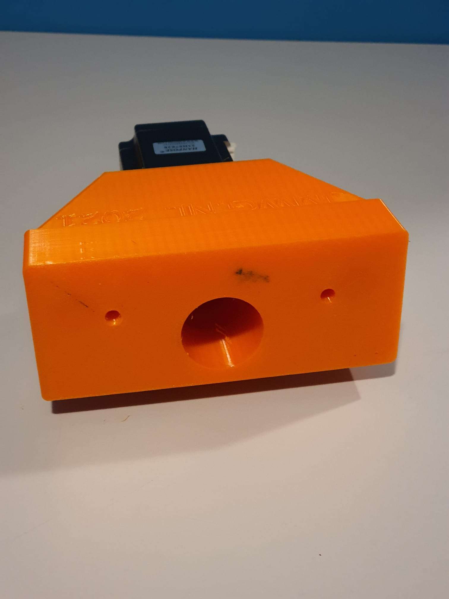
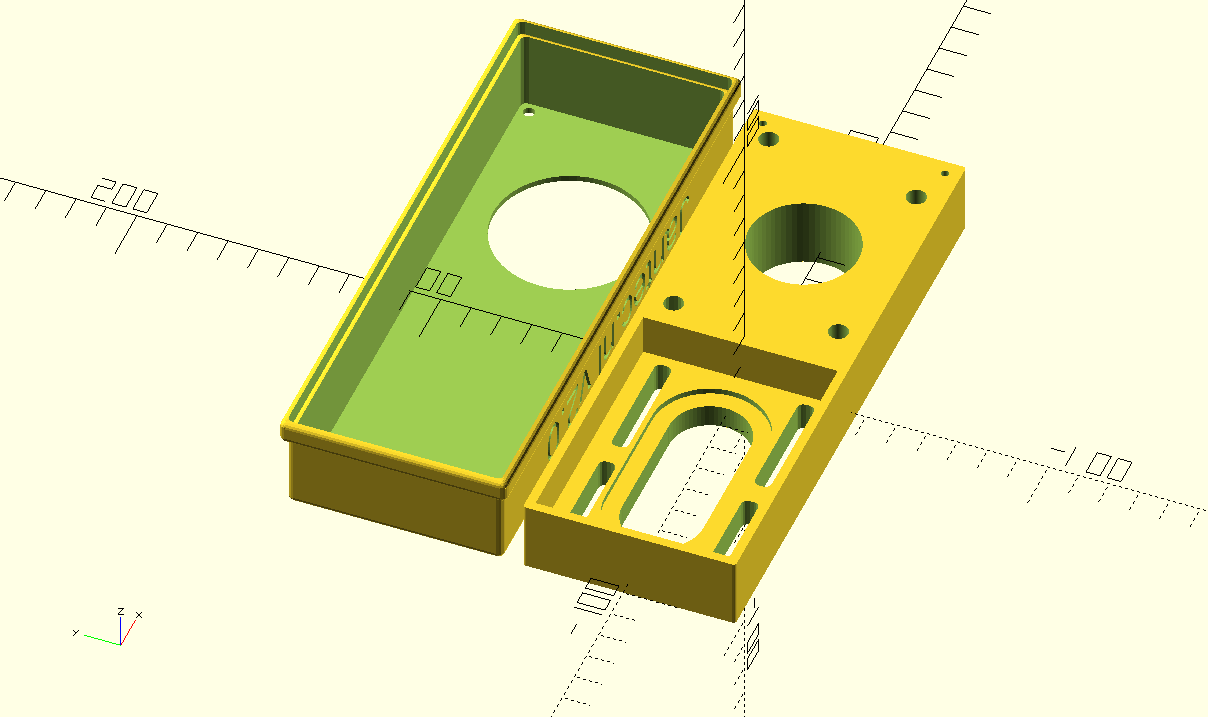
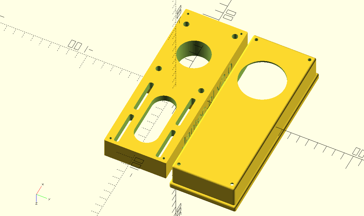
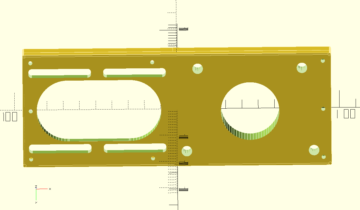
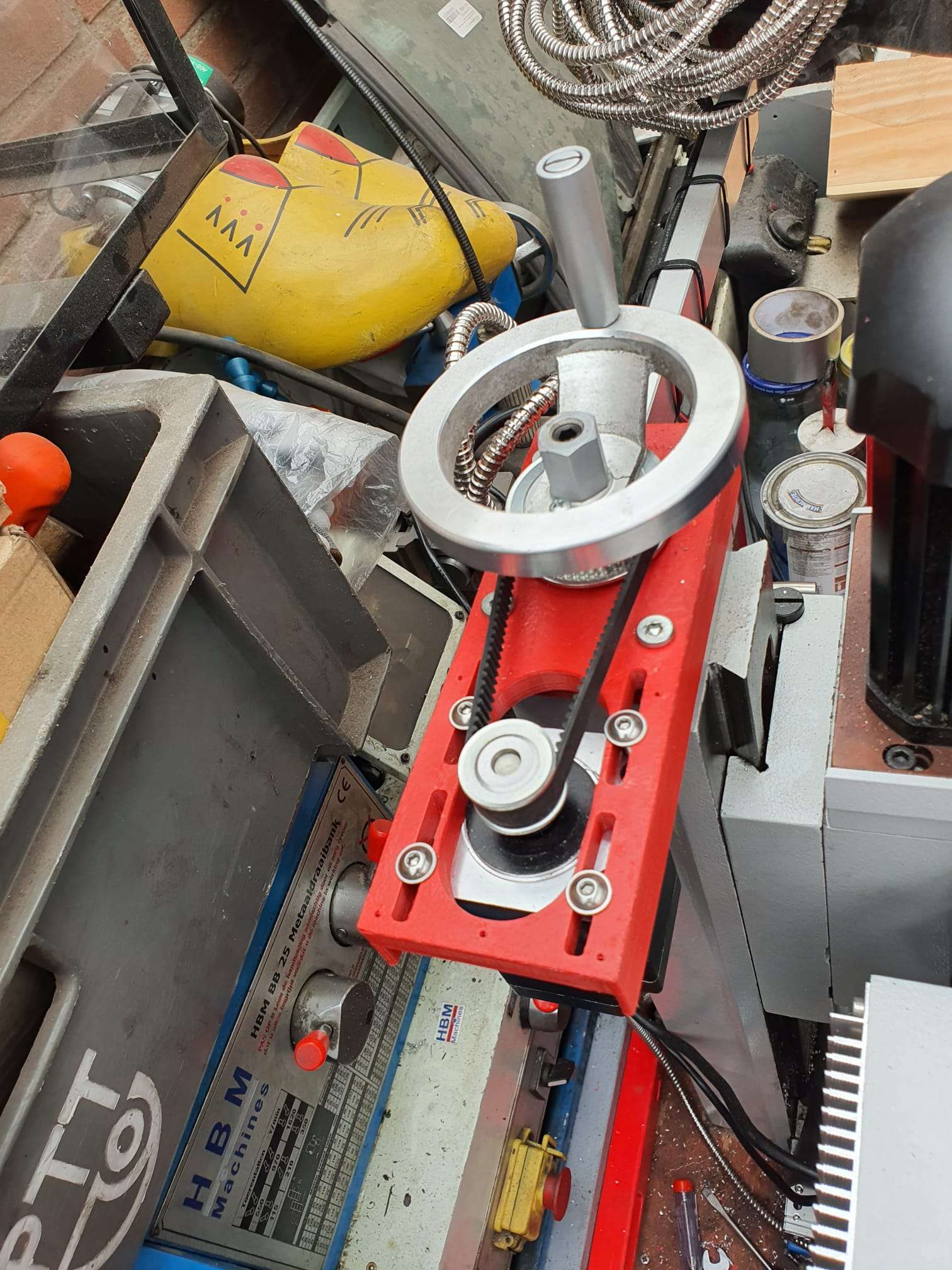
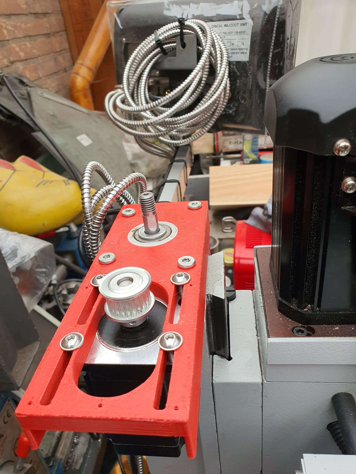
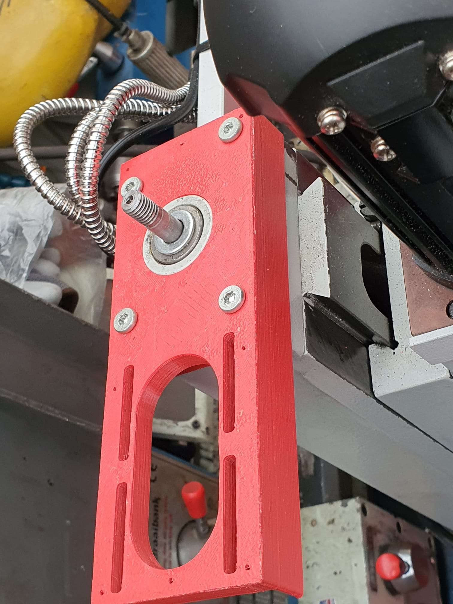
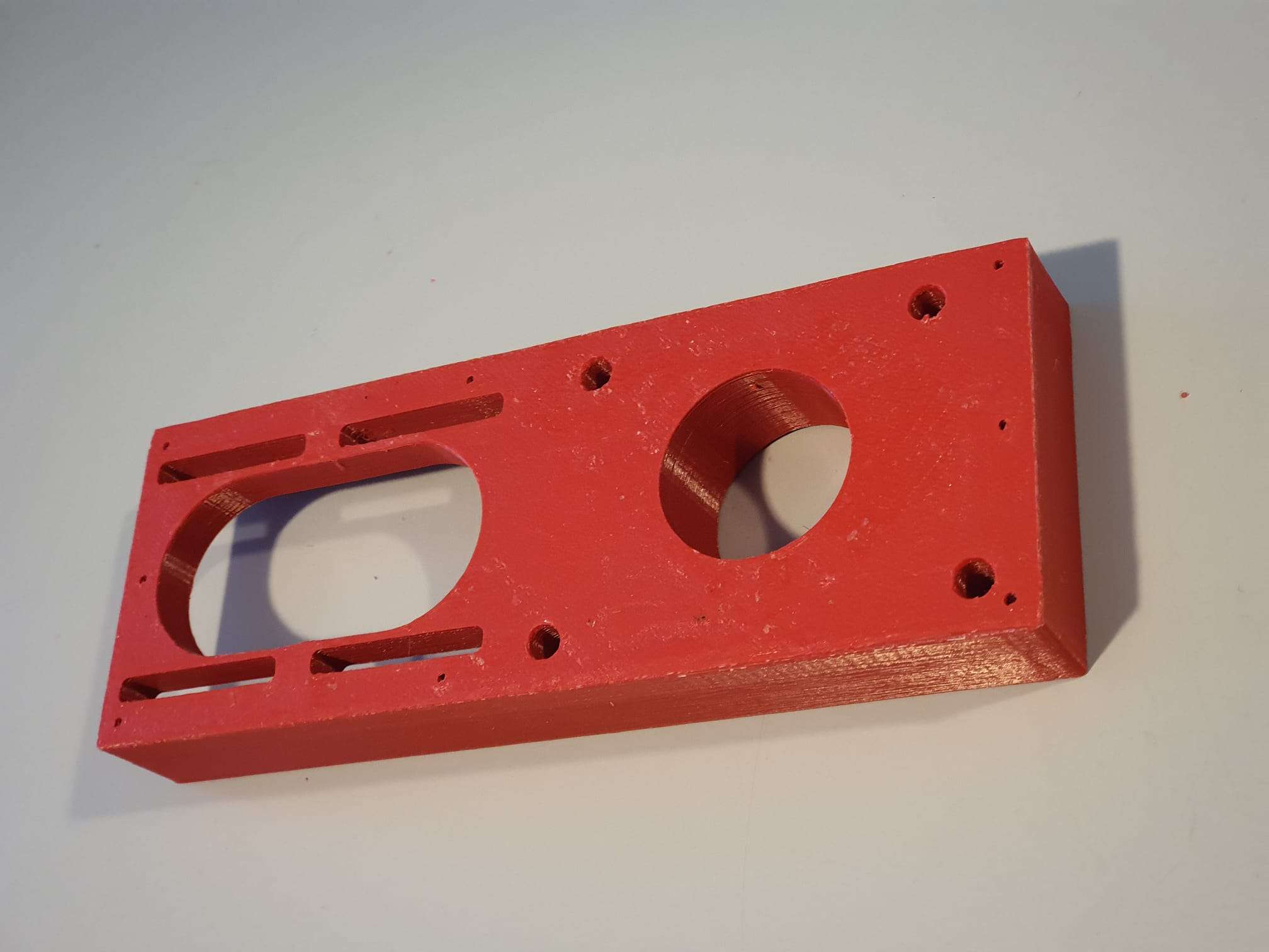
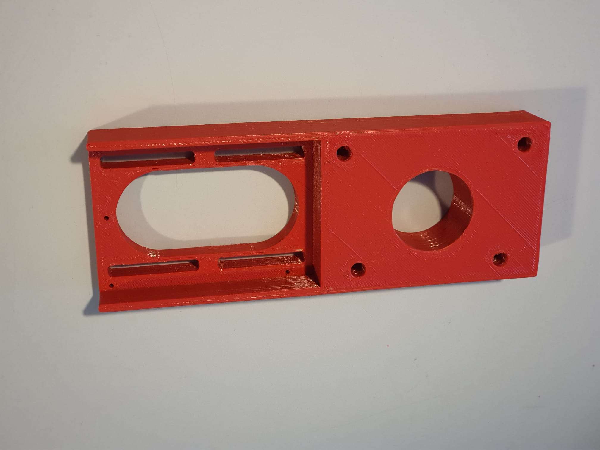
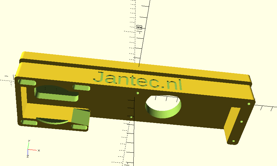
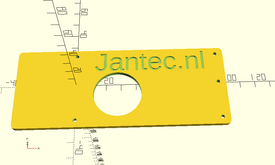
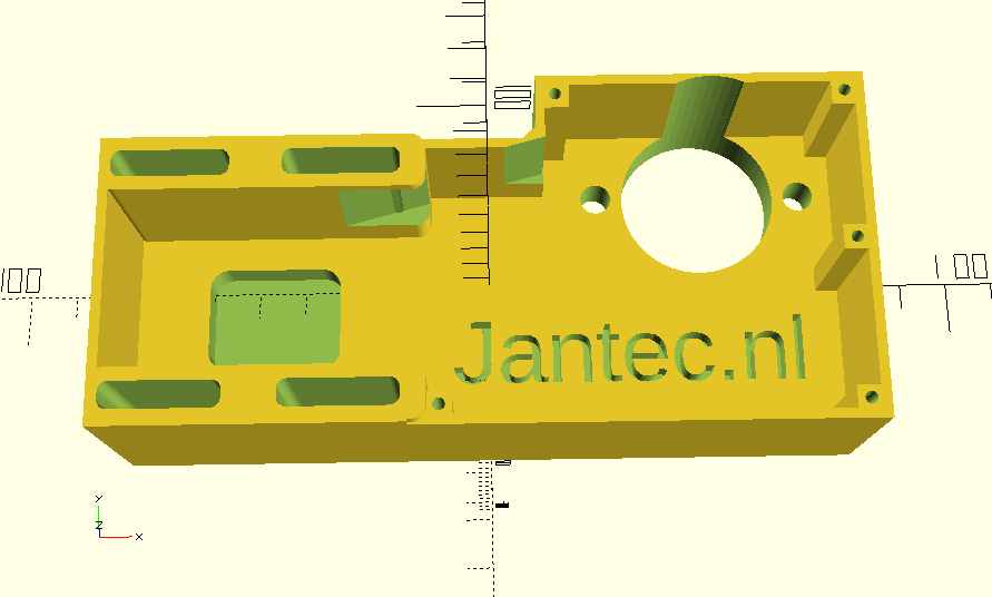
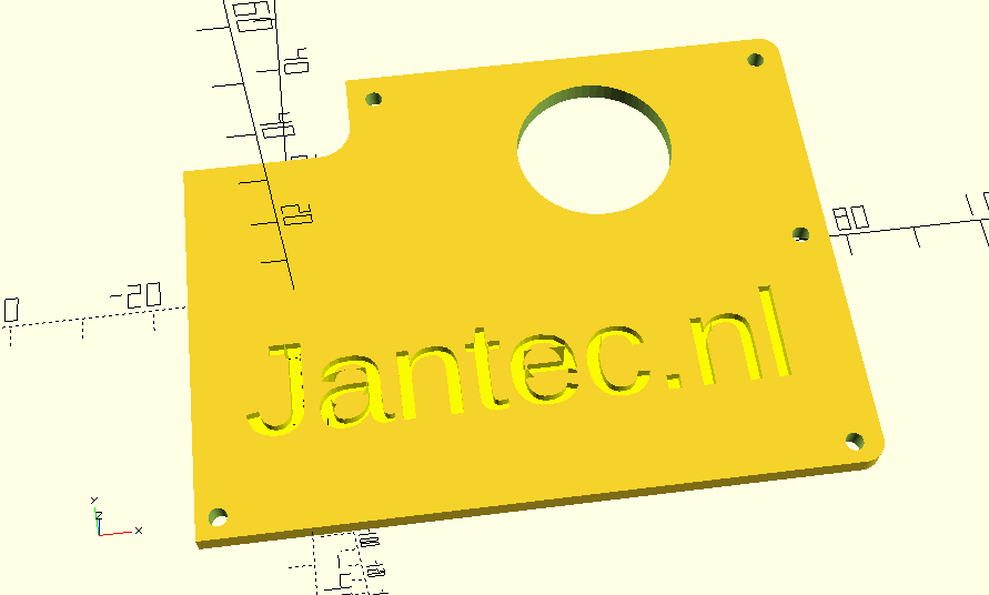
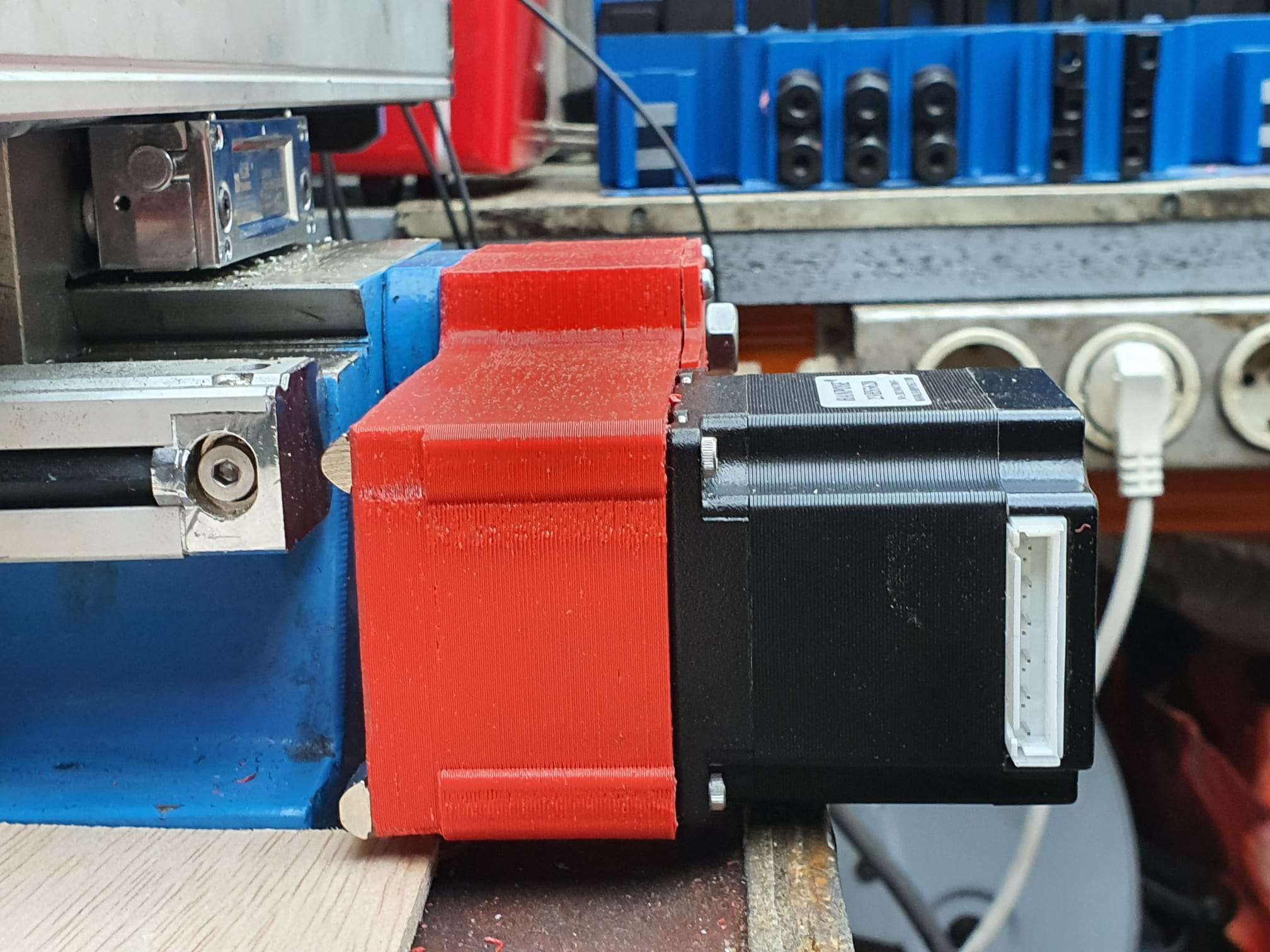
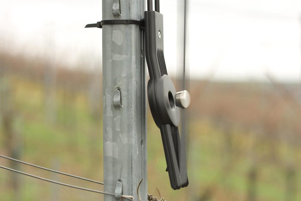
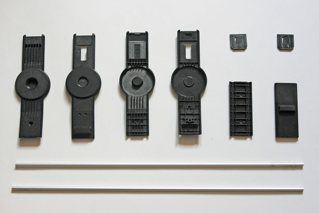
Wolfang GA200 action camera mini rig STL download

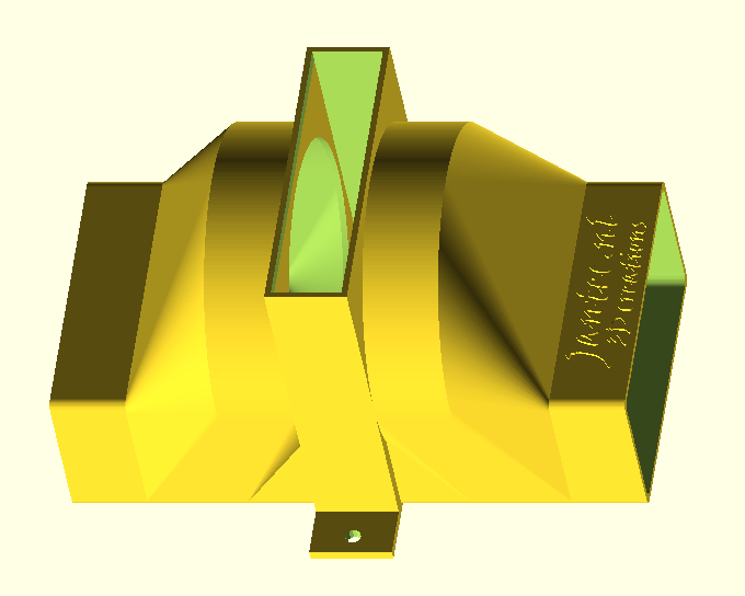
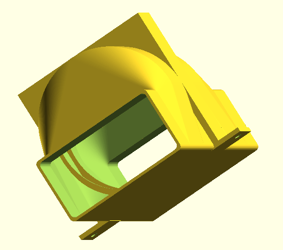
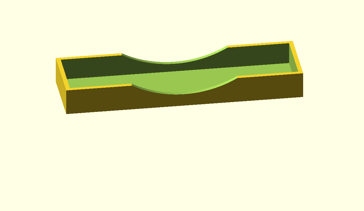
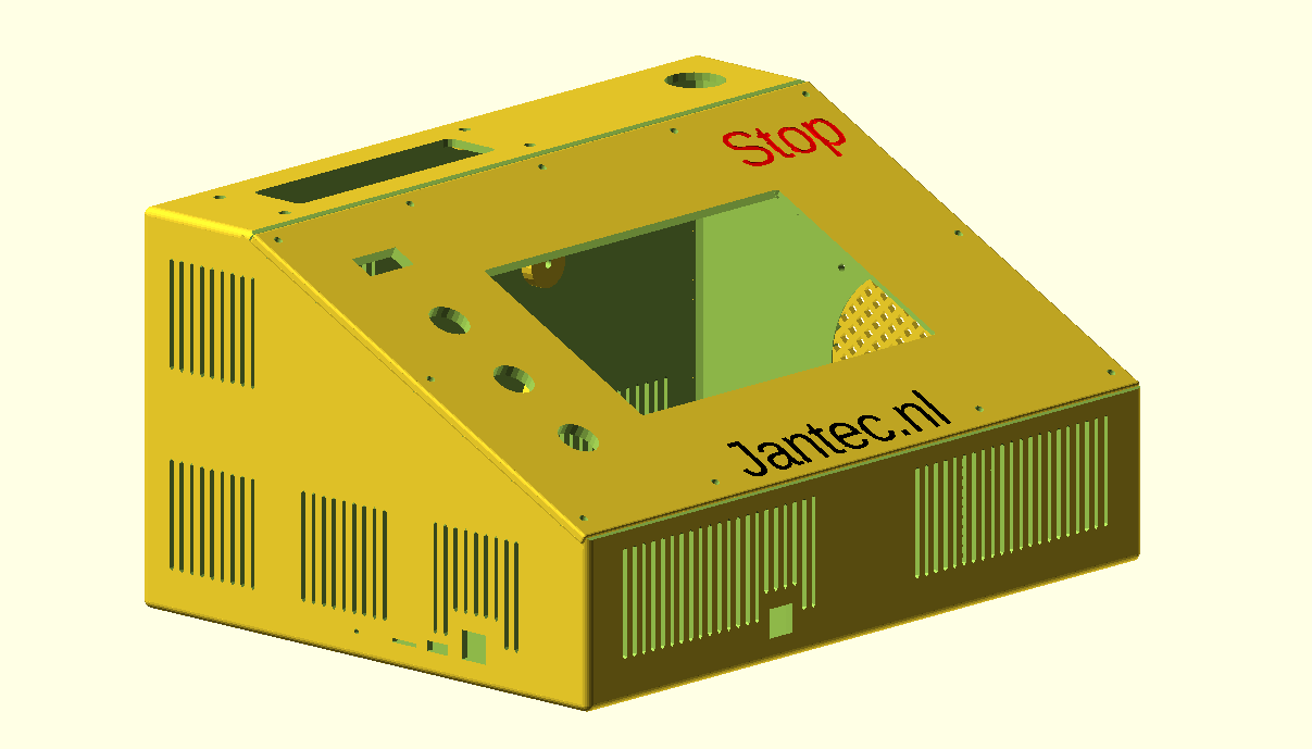
Wolfang_GA200_4k_videocam_smallrig_20260318_V11G_jantec.nl


Please donate $1 to my paypal account if you use this original jantec.nl design  -)

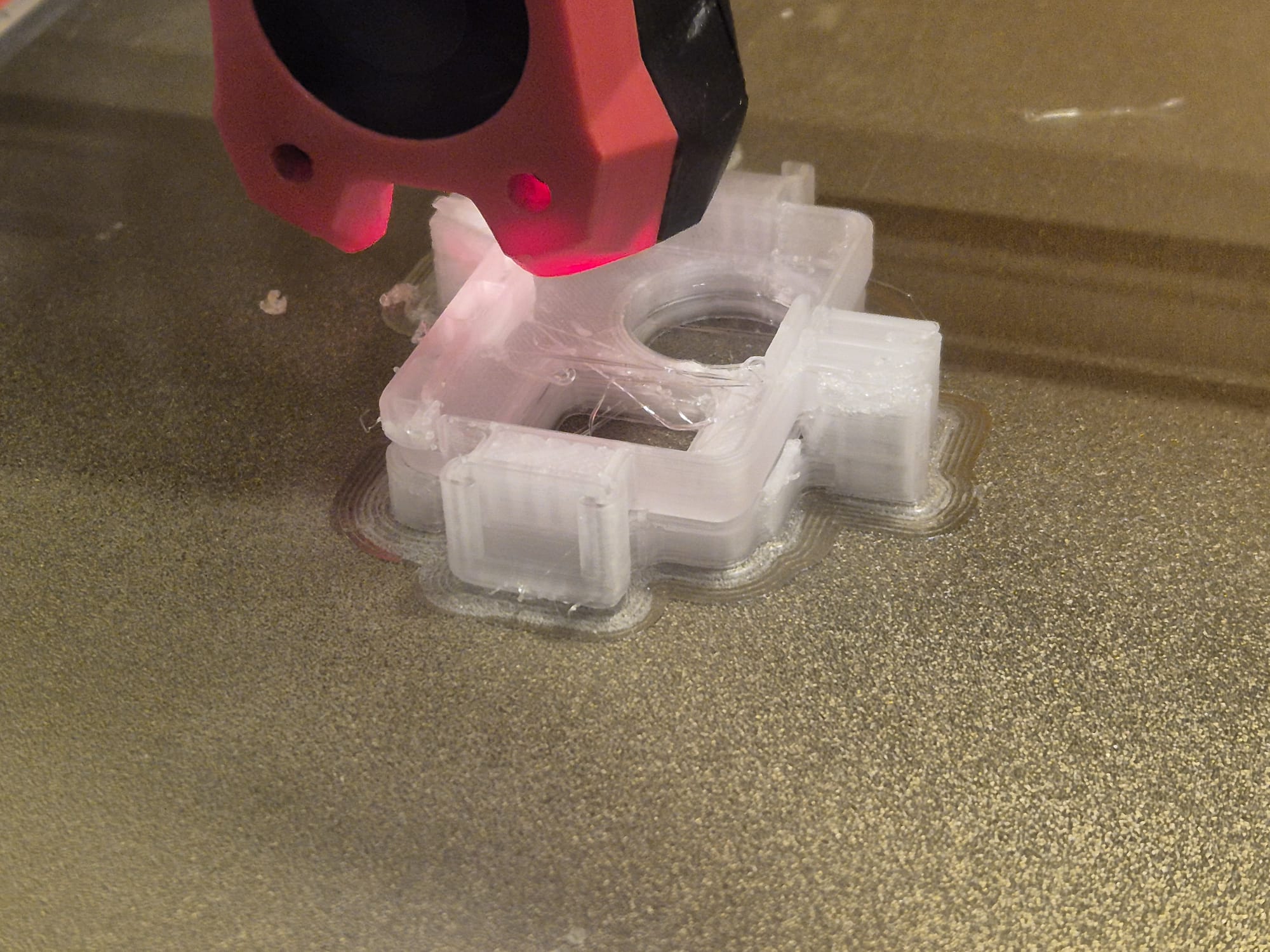
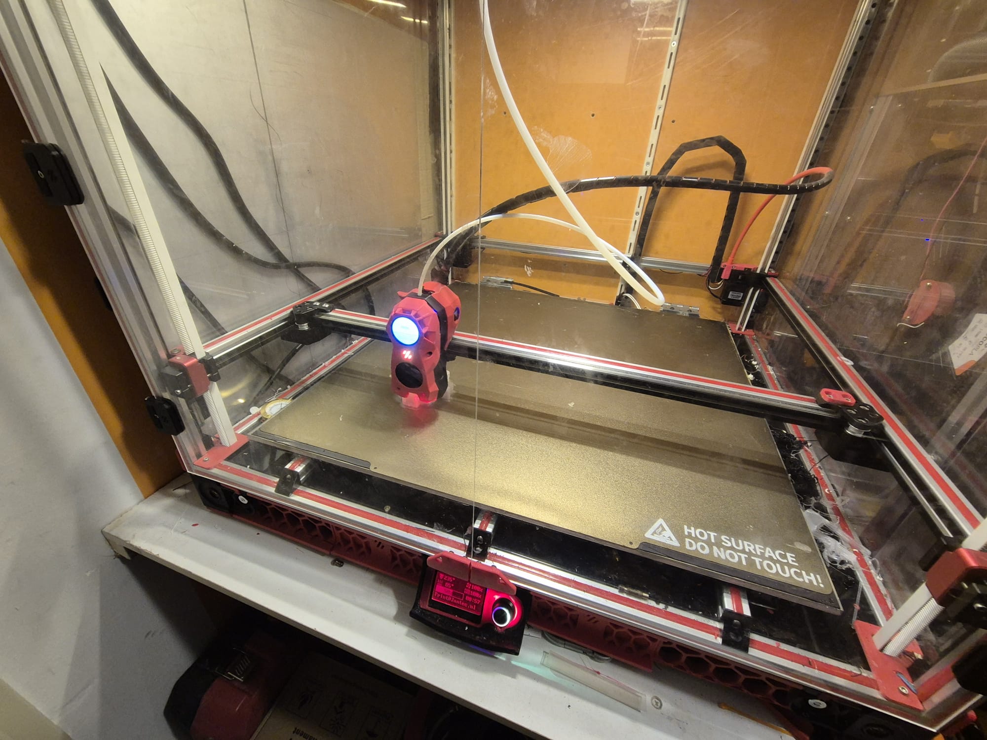
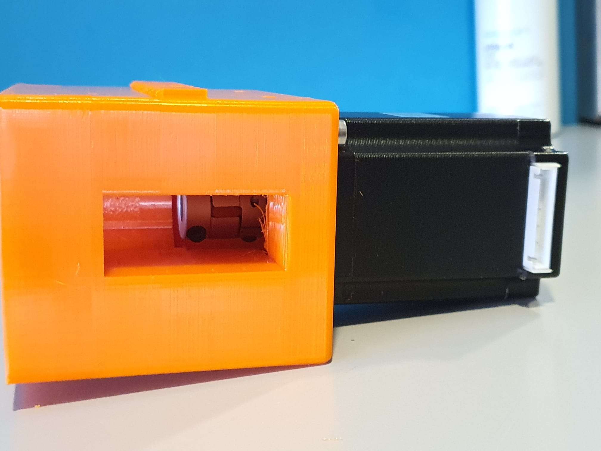
Printed on Voron 600 @ 0.3 mm LH and 0,8mm nozzle, transparant PETG. Hispeed in 1 hour at 100% infill, front down, brim 0.2 mm thick, 10mm wide. Supports everywhere in matrix mode @ 10mm wide, big gap 0.5mm top of Z and 1.2 mm on X/Y spacing. Temp 235 deg nozzle, 85 deg bed. 100% fan except for 1st 3 layers.

STL download acoustic guitar string tuners plastic pegs repair with 3d printed covers

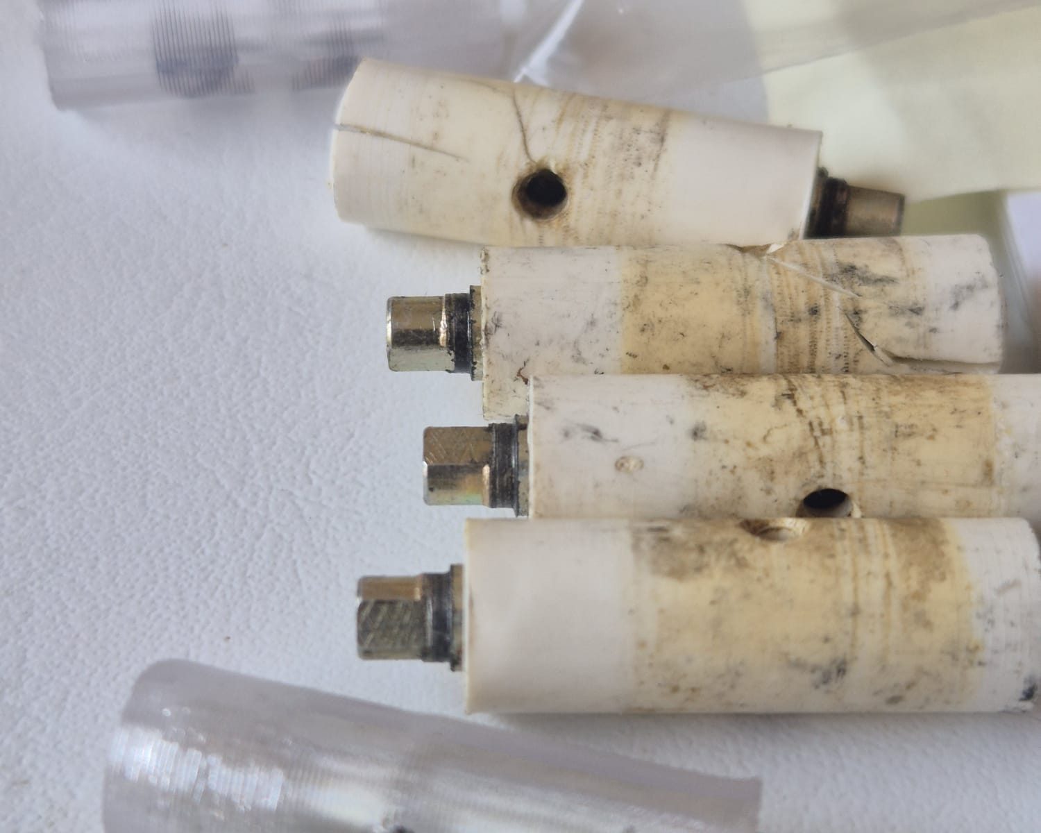
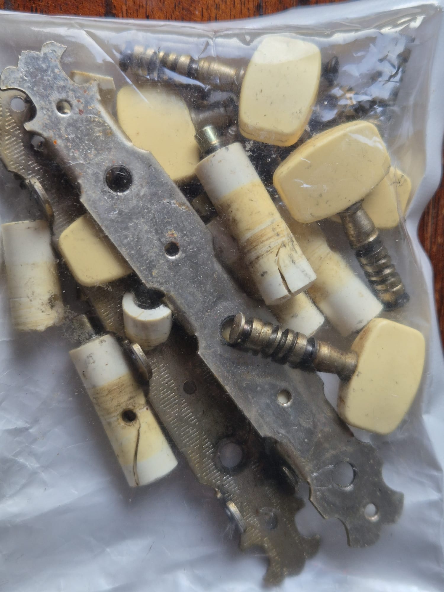
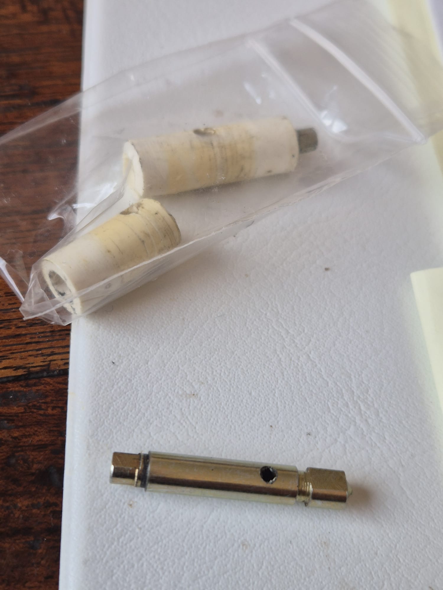
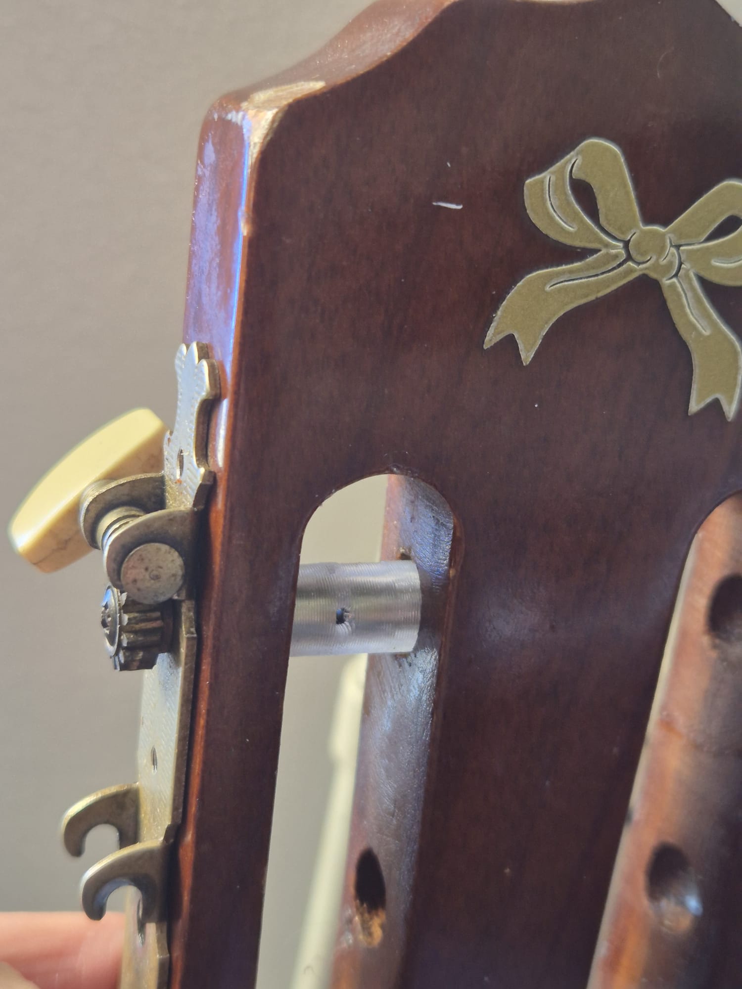
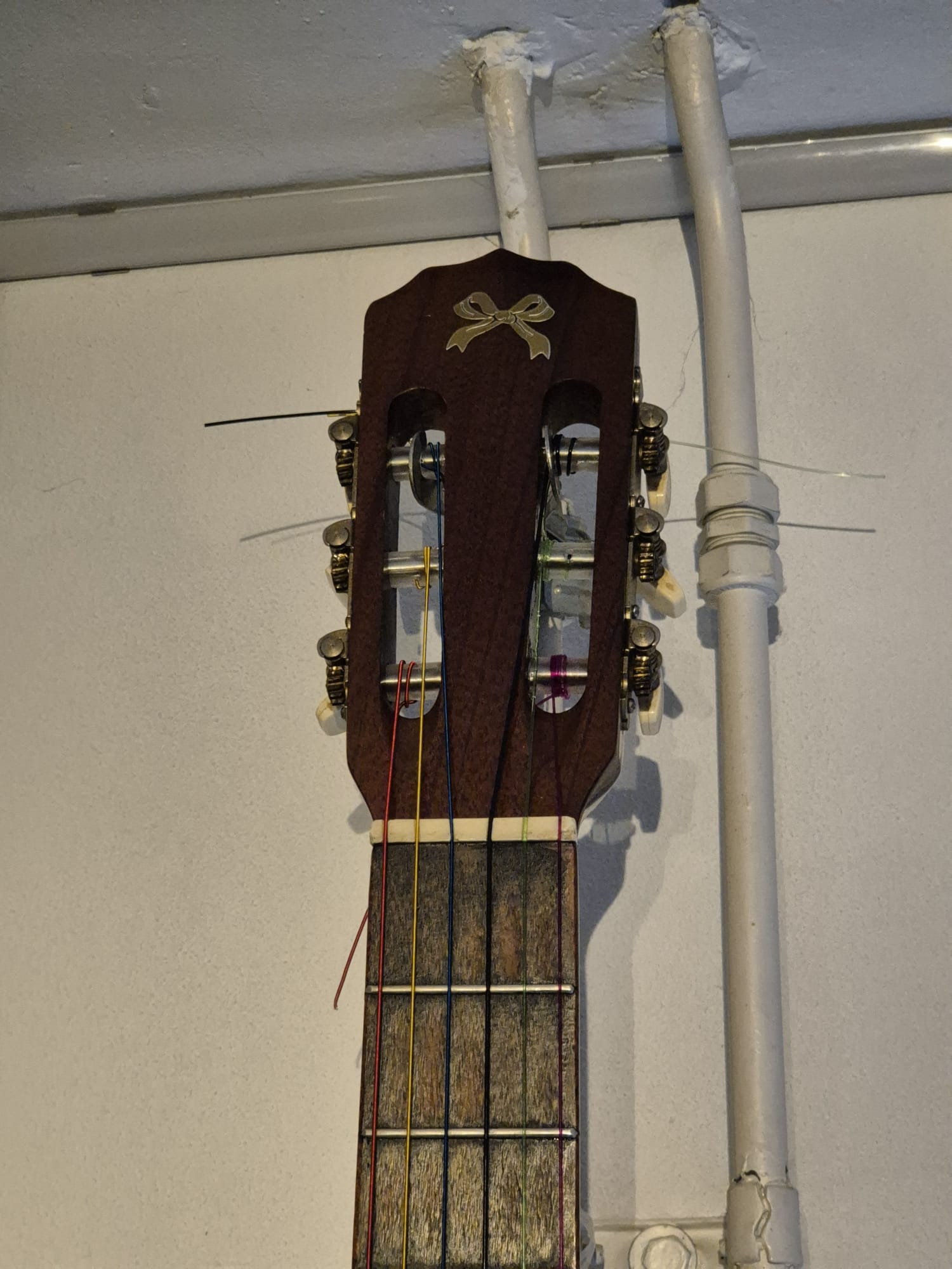
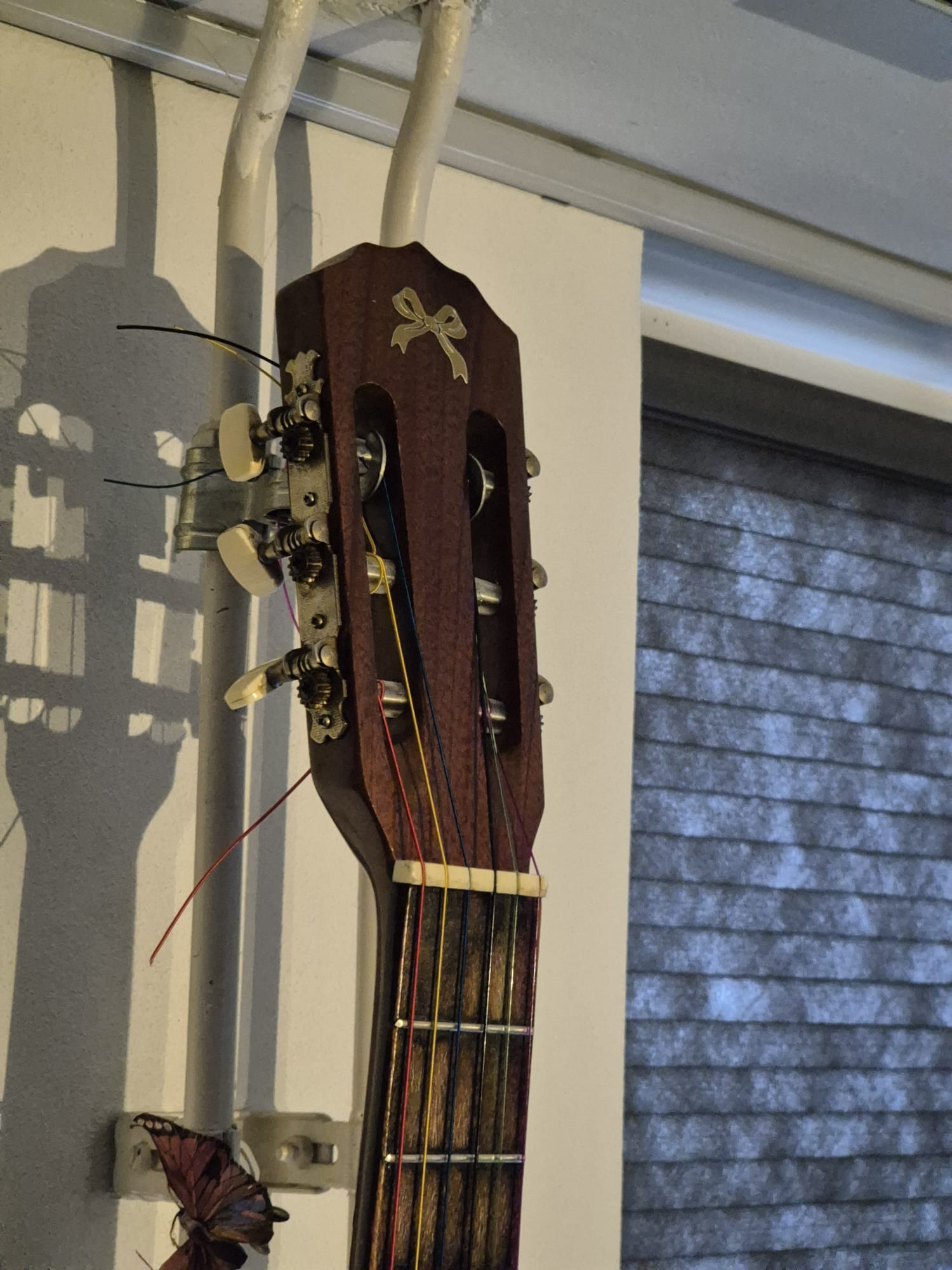
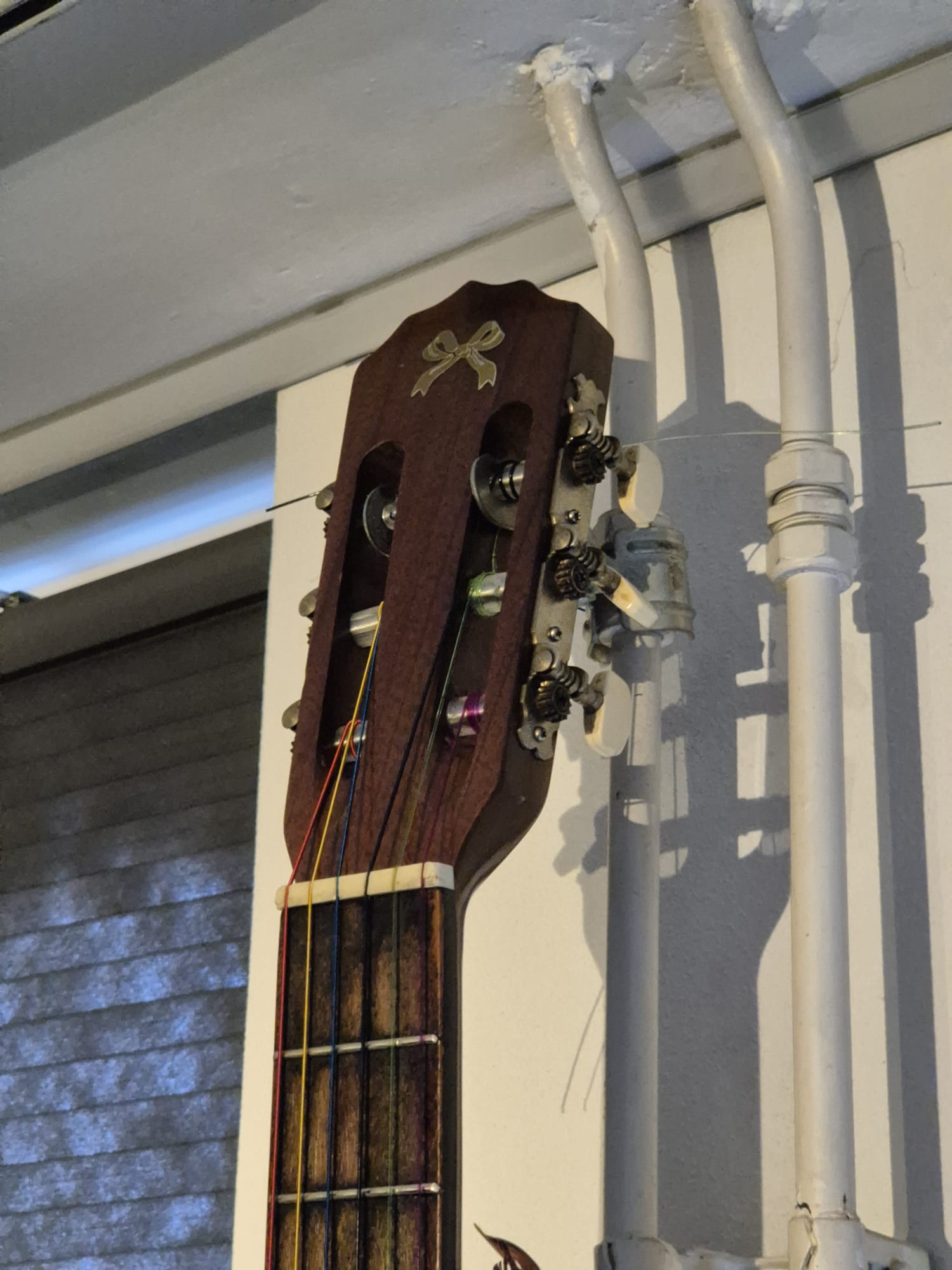
One of my very old DIY elktro-acoustic guiters had broken tuners on it. I did not want to order me new ones, since the mechanics were Ok, it was just the plastic covers that were all more or less torn up.

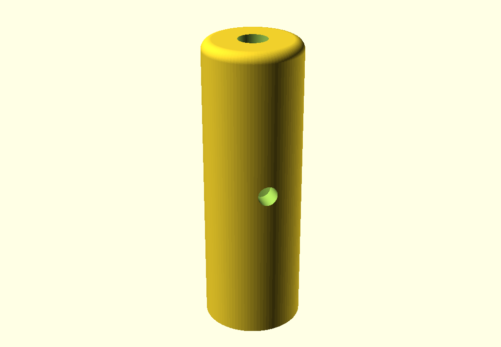
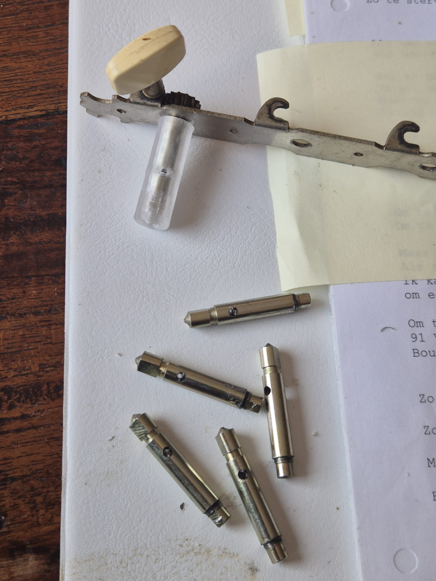
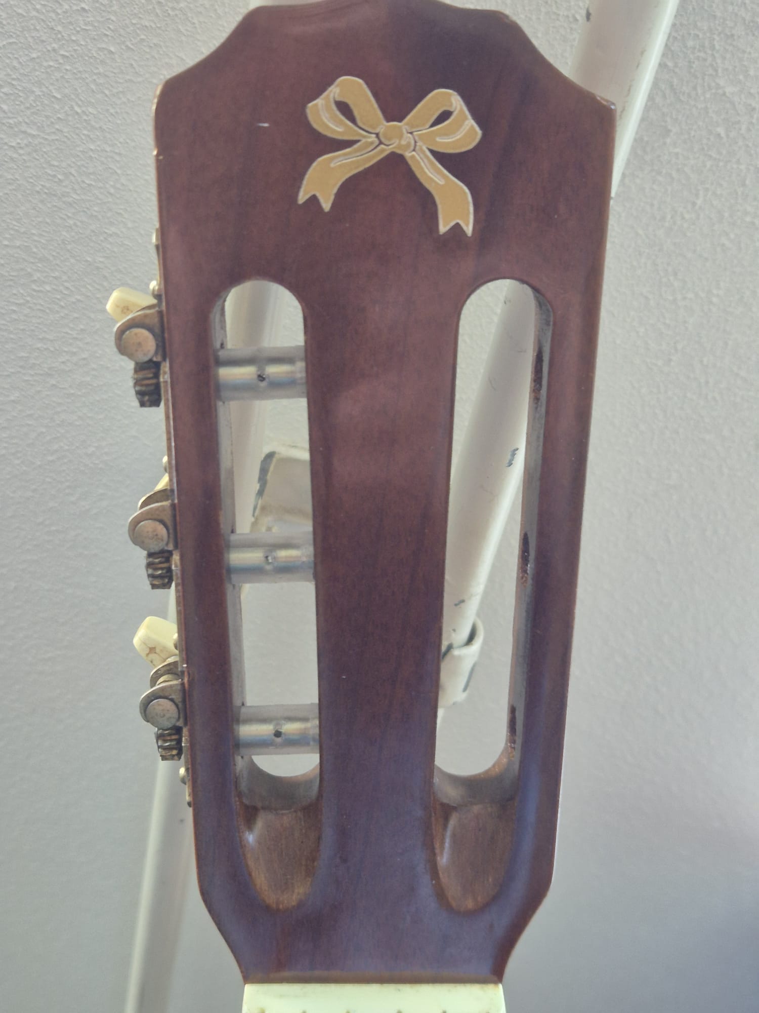
In Openscad, I designed the to be 3d-printed sleeves that fit around the metal tuner shafts.

acoustic_old_guitar_tuner_plastic _replacement_part_5.9mmID_10mmOD_30mmL_V3_20260305

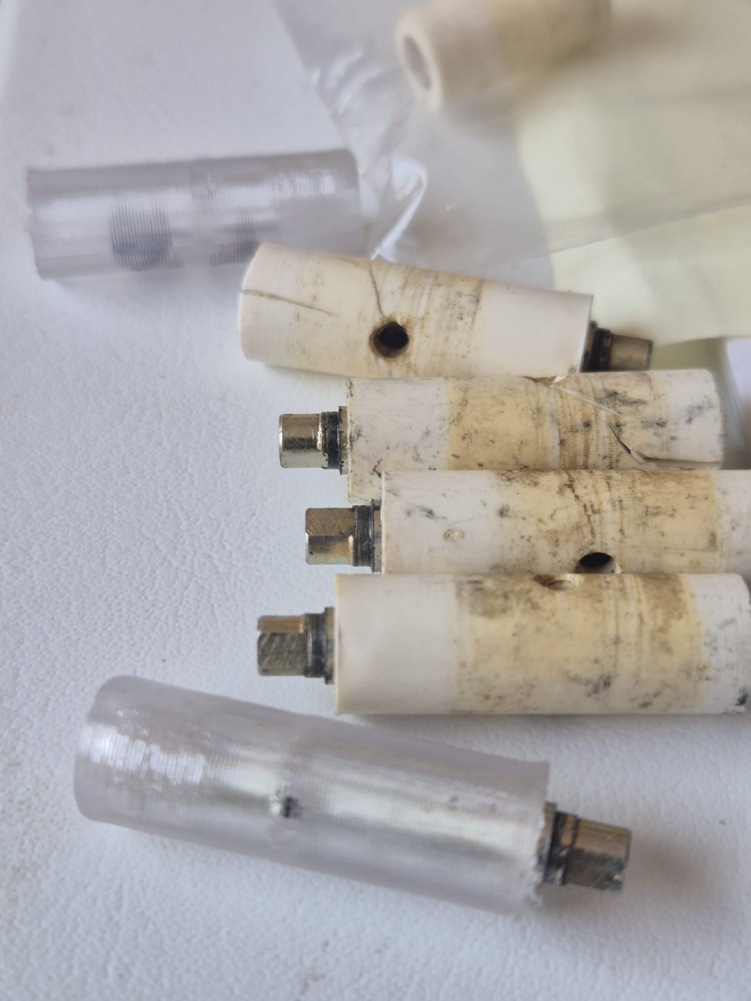
I printed 6 sleeves in transparant PETG on the Voron 600 (0.8 mm nozzle, 0.3mmLH, 235deg nozzle//85deg bed.

No supports, although I did use a firm brim around the shaft.  I printed the sleeves one at a time, in 7 minutes each.

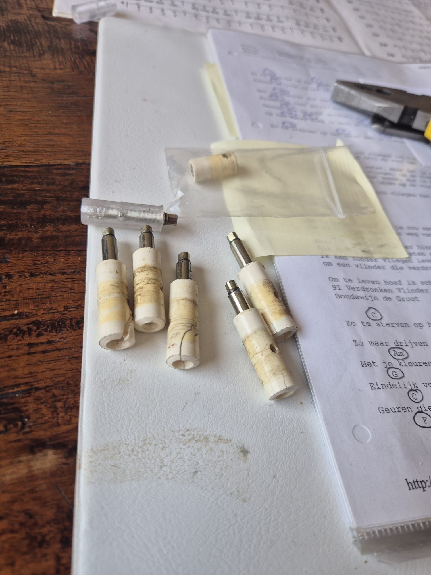
The old shafts were tapped out of the metallic shafts. I used my vice and opened the vice’s jaws just enough to tap the shafts out of the sleeves.

Mounting the sleeves around the shafts is pretty easy, since the hole in the shafts and sleeves can be lined up due to the transparancy of the PETG material.

The shafts fit easily in the sleeves, although I used the vice to push the shaft in for the last 1-2 cm, due to the tight fit of the shaft in the inner sleeve’s recess that makes the sleeve follow the circular motion of the shafts when tuning the strings.

When installing the tuner sets, I used some vaseline around the plastic sleeves where they meet the holes in the tailstock wood so the sleeves don’t get stuck.

The process of de mounting and mounting the sleeves and the tuner sets is pretty self-expalinatory, please have a look at the below added photo’s!

BTW, I made 2 versions of the sleeves.

The one I used on my fast Voron600 is a bit wider inside (shaft diameter +0.4mm) .

This is needed due to the fact that little holes are always printed smaller on my Voron600 with the 0.8mm nozzle  than designed.

If you want to print the sleeves with an accurate 3d printer, the exact fitting design is HERE:  acoustic_old_guitar_tuner_plastic _replacement_part_5.6mmID_10mmOD_30mmL_V3_20260305

free STL downloads in 7 parts for CNC controller box with mounts for Duet3-6HC, PSU, AC-inlet, multiconnector, emergency shut-off, LCD panel, homing buttons and DC outlet

CNC_ctrlbox_V21_DUET3_6HC_LCDPANEL_C)JANTEC.NL_20251115

CNC_ctrlbox_V21_DUET3_6HC_TOP_PART_C)JANTEC.NL_20251115


CNC_ctrlbox_V21_DUET3_6HC_REAR_PART_C)JANTEC.NL_20251115


CNC_ctrlbox_V21_DUET3_6HC_FRONT_PART_C)JANTEC.NL_20251115


CNC_ctrlbox_V21_DUET3_6HC_BOTTOM_PART_C)JANTEC.NL_20251115


CNC_ctrlbox_V21_DUET3_6HC_RIGHT_PART_C)JANTEC.NL_20251115


CNC_ctrlbox_V21_DUET3_6HC_LEFT_PART_C)JANTEC.NL_20251115

ALL IN ONE BOX as 1 STL FILE:

CNC_ctrlbox_V21_DUET3_6HC_allinonebox_C)JANTEC.NL_20251115


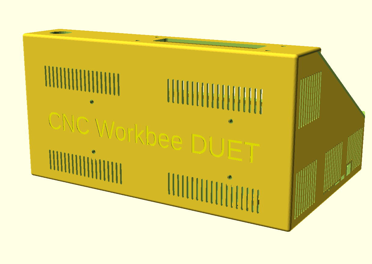
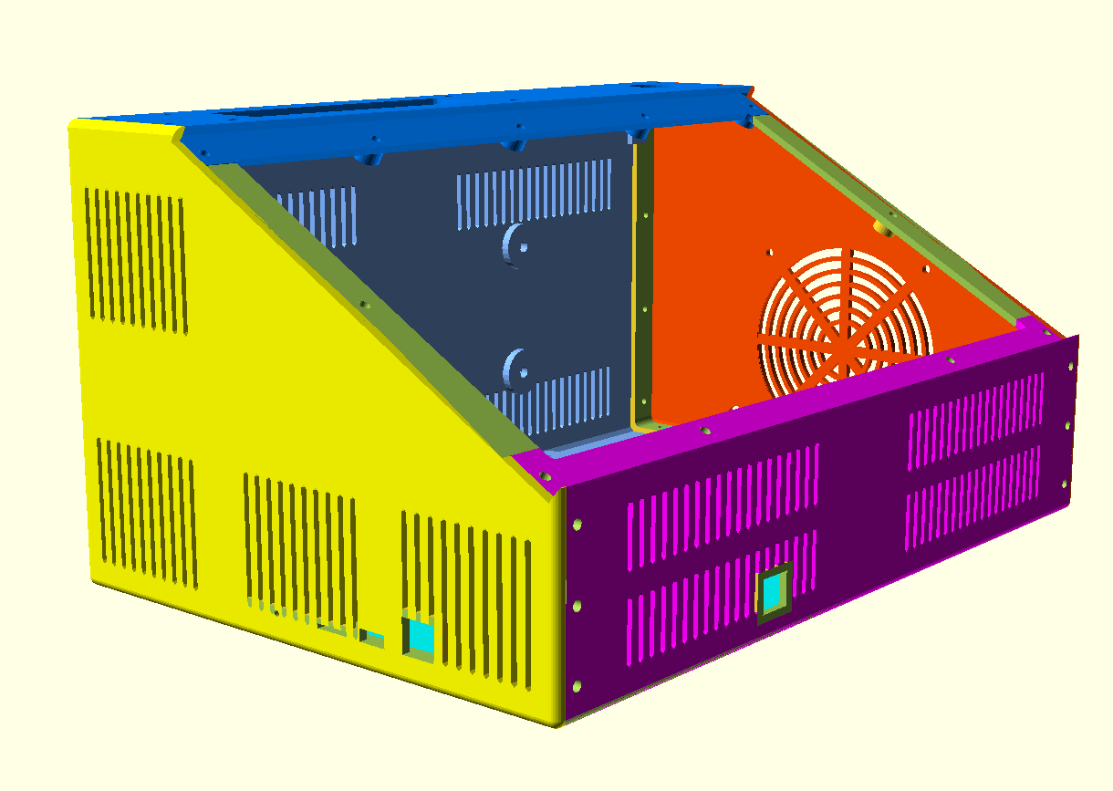
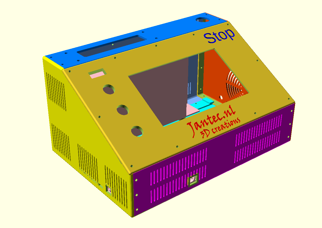
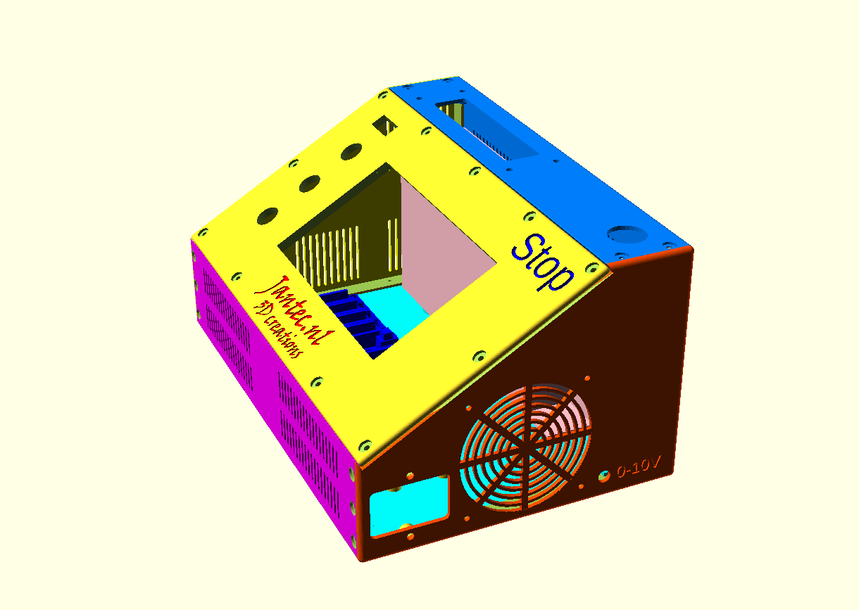
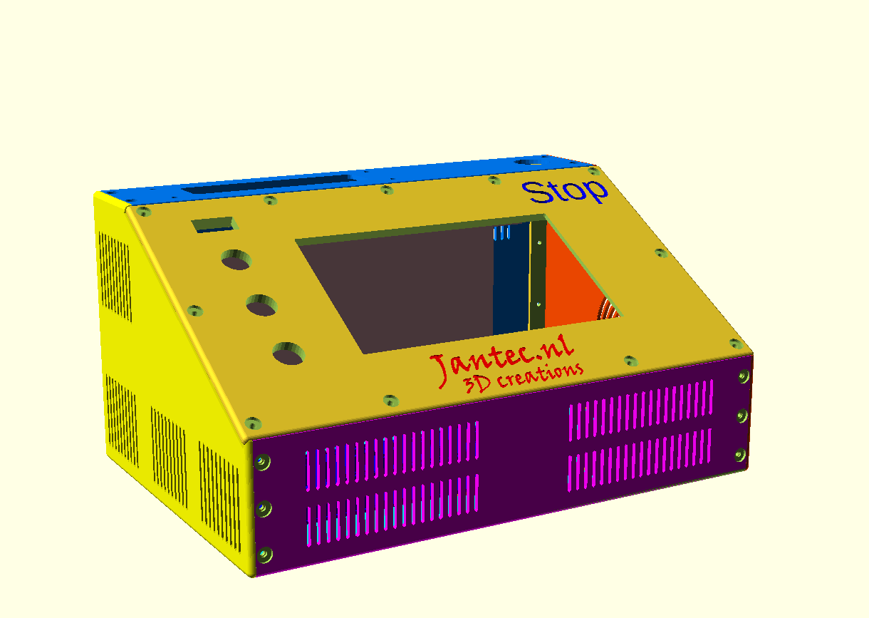
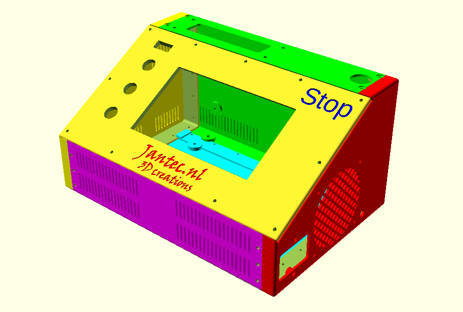
CNC controller case free STL download Duet workbee Mellow FLY CDY with PSU, panic button, multiconnector and Fysetc Duepanel 7 inch

DOWNLOAD CNC_controller_box_6_parts_V2_C)JANTEC.NL_20251102

Please donate $1 to my paypal account if you use my original designs  -)

THE CNC CONTROL BOX

Download the CNC controller box design file via the above link in 1 piece which will take around a day or more to print.

The CNC box design is available in 6 separate design STL parts that interlock very well and  will have to be glued and (if you so desire-screwed) together.


The box is also available for DUET3 HERE

THE ENTIRE CNC CONTROLLER BOX AS 1 STL FILE:

THE ENTIRE CNC CDY CONTROLLER BOX AS 1 STL FILE: 

THE CDY BOTTOM PANEL:

THE ’empty’ BOTTOM PANEL: 

THE  LEFT PANEL:


THE  RIGHT PANEL:

THE  FRONT PANEL:

THE  REAR/TOP PANEL:

THE TILTED TOP PANEL:

REAR TOP PANEL PART CNC FLYCDY CONTROLBOX BY JANTEC.NL

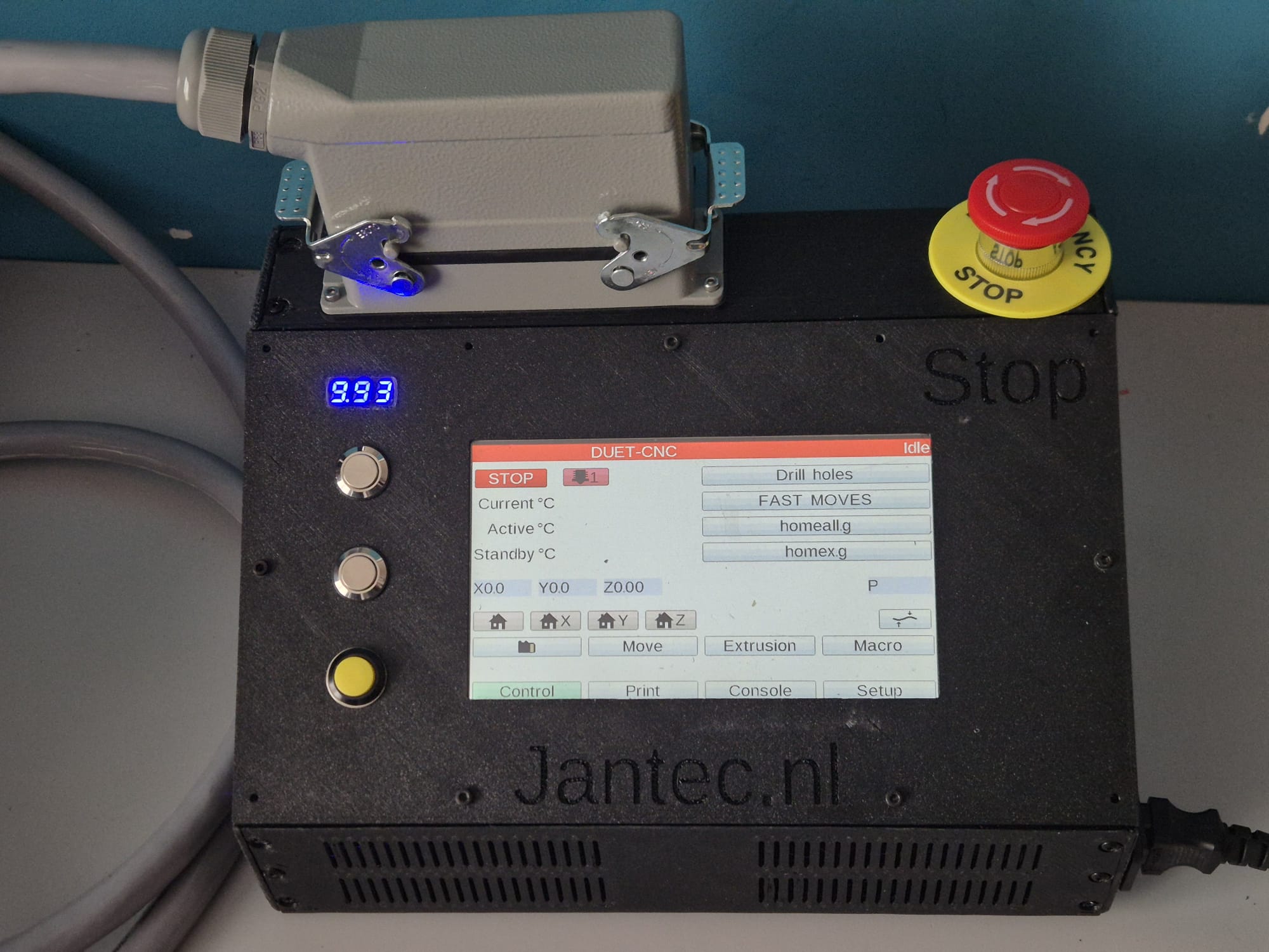
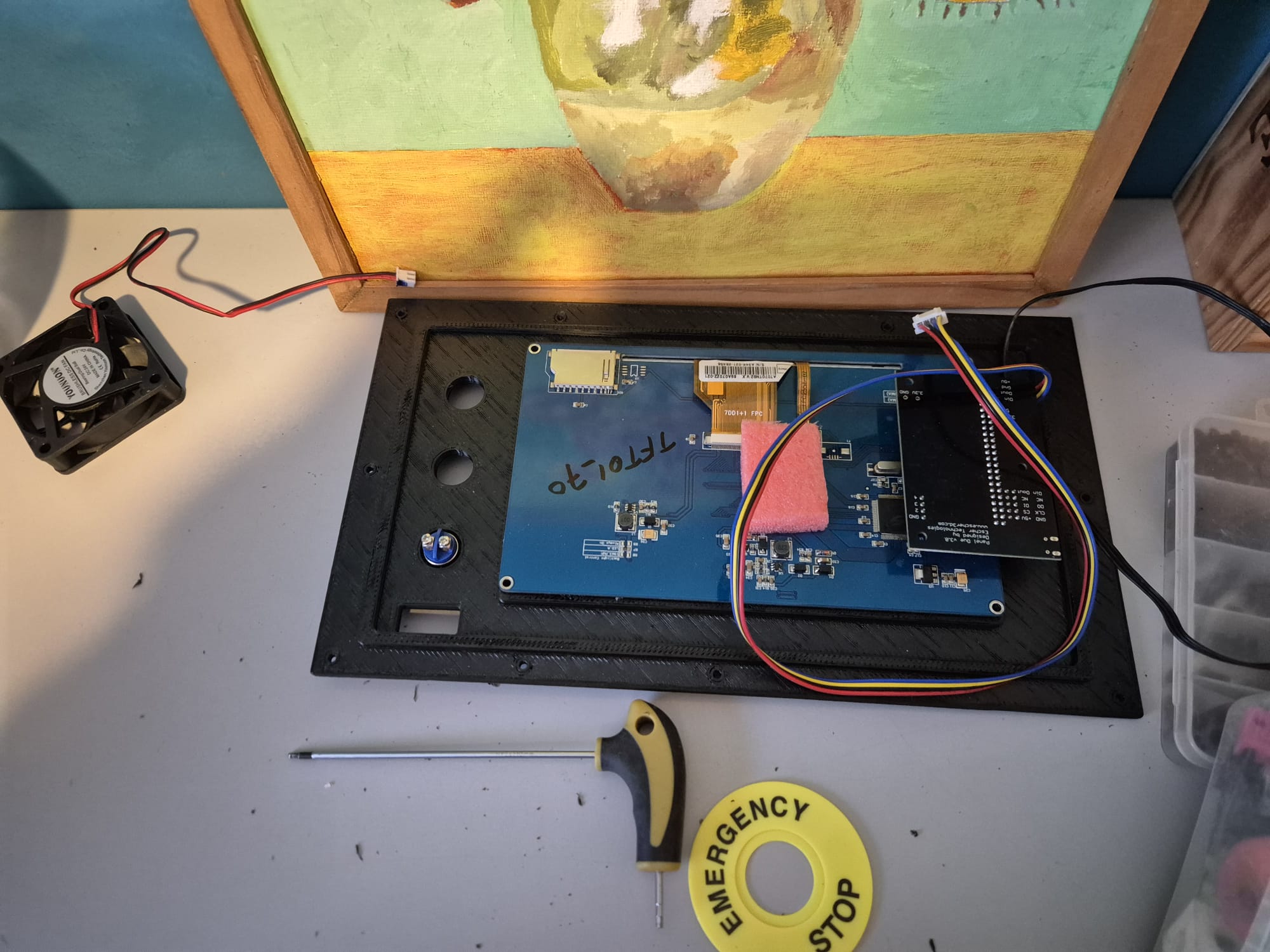
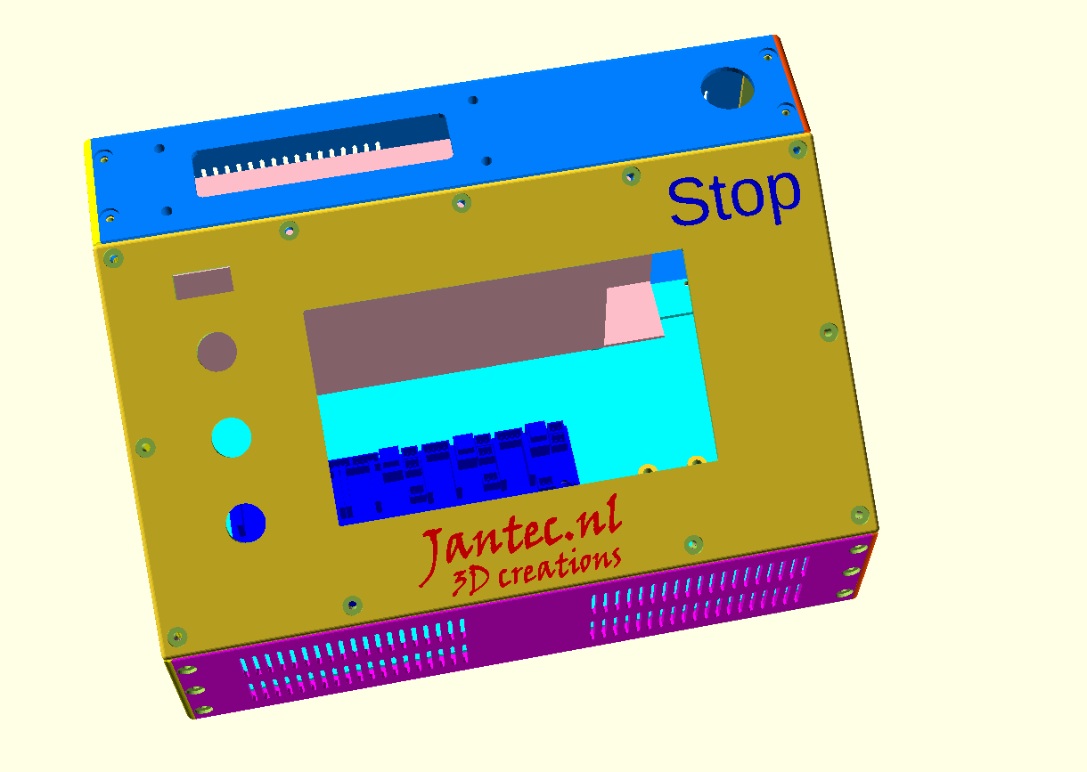
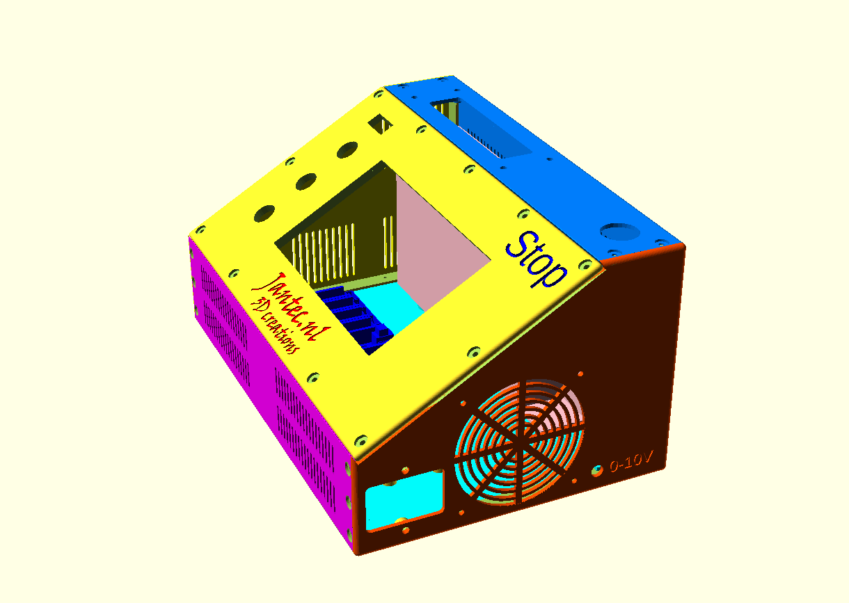
The tilted top panel  houses a FysetC Duepanel 7 inch LCD module that interconnects to the FlyCDY2 or 3 ( and will also fit to the Duet3, obviously).

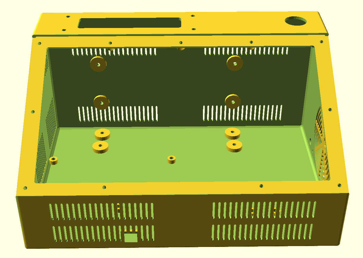
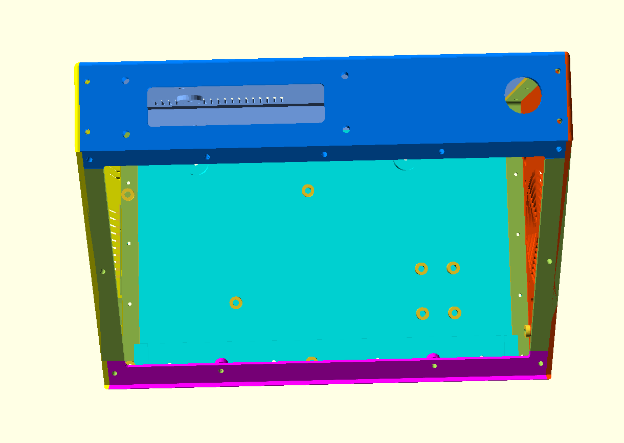
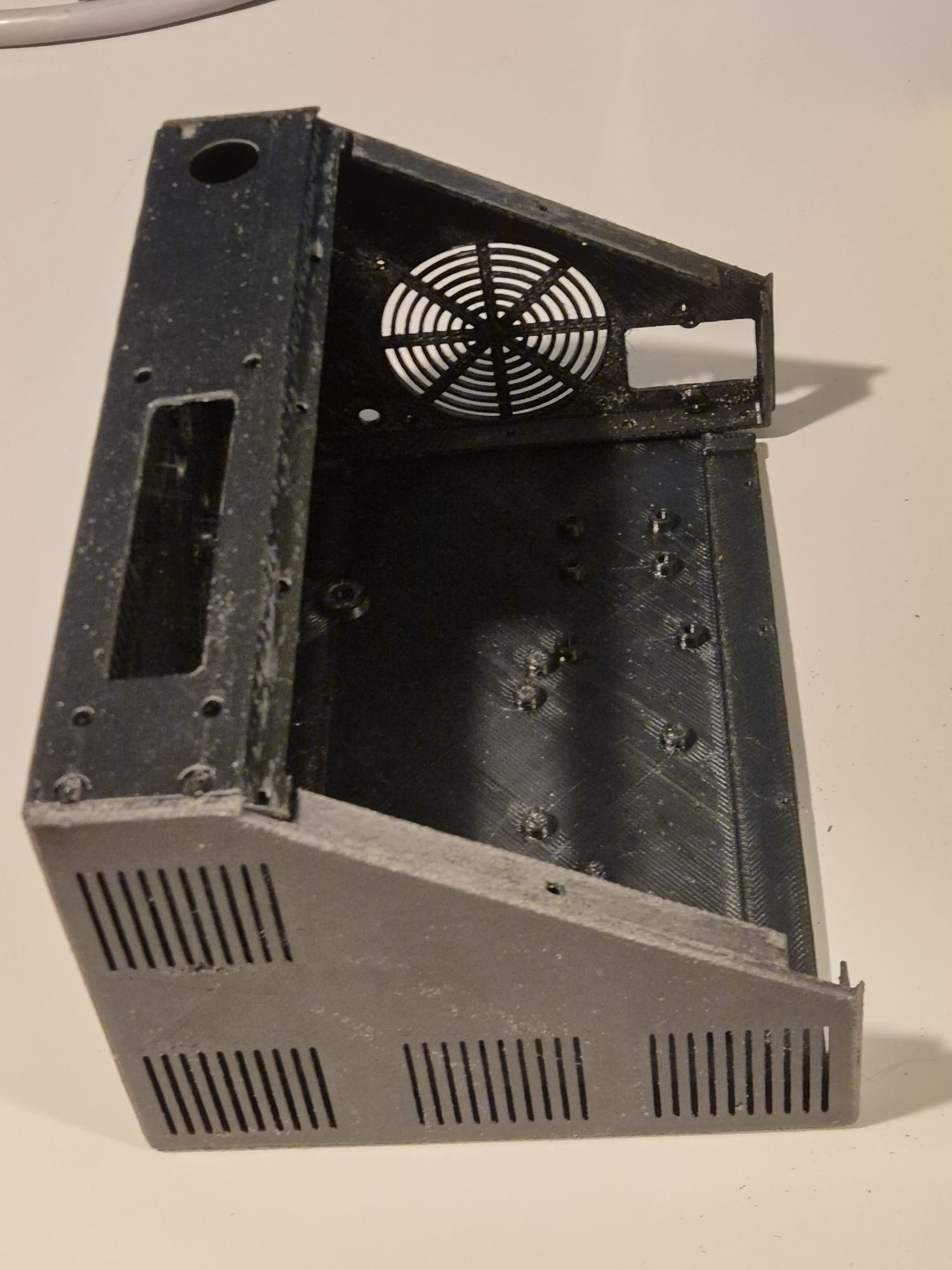
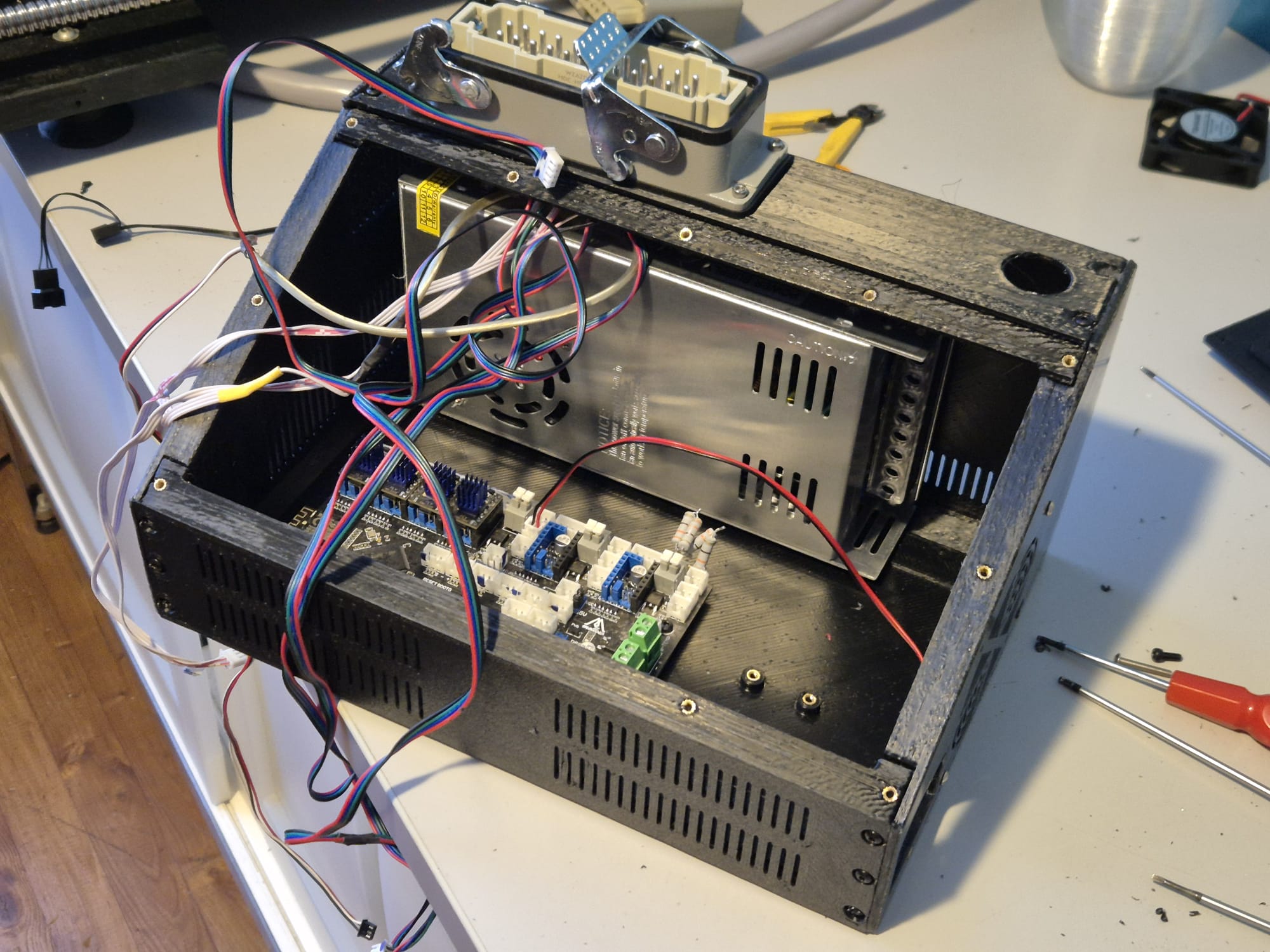
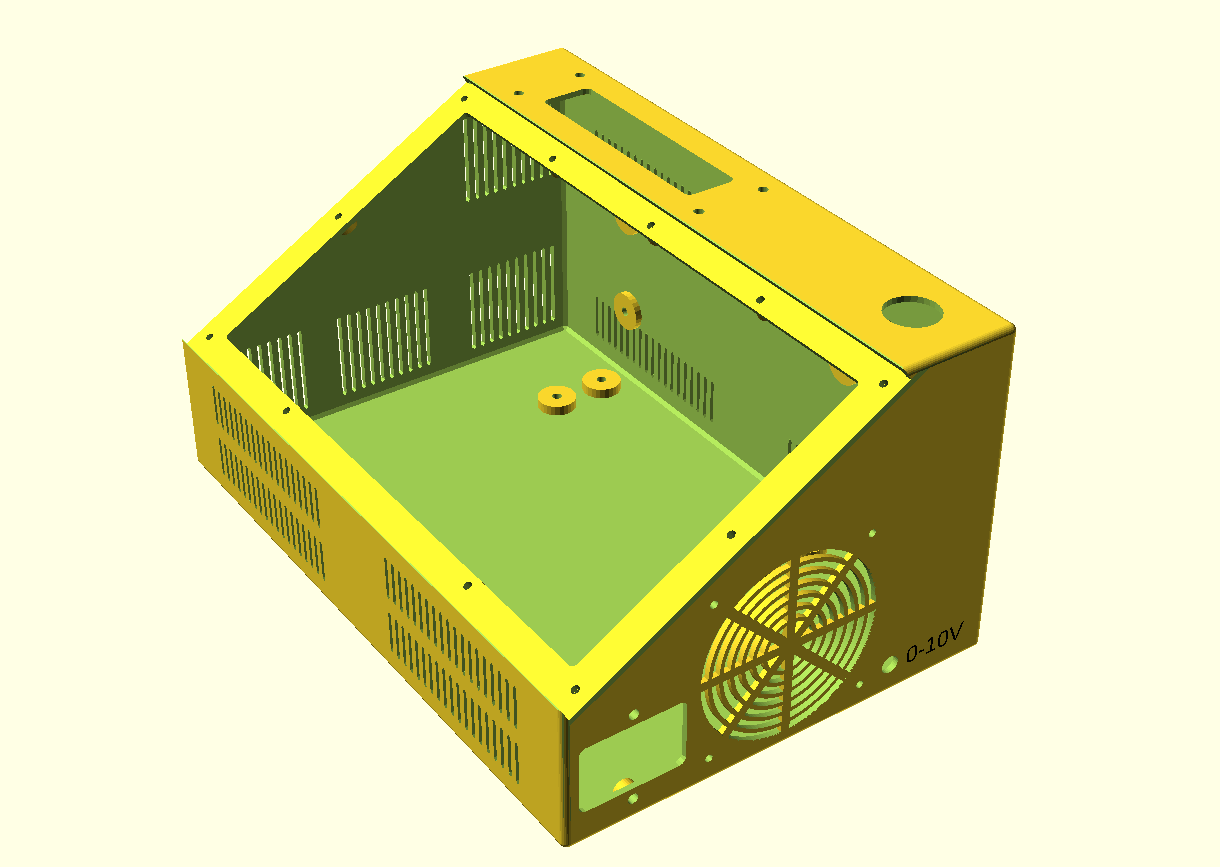
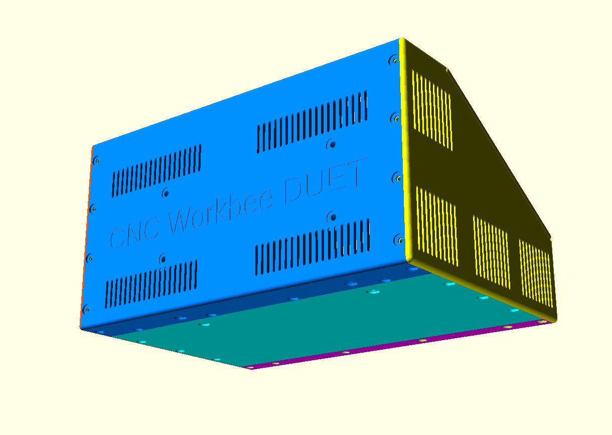
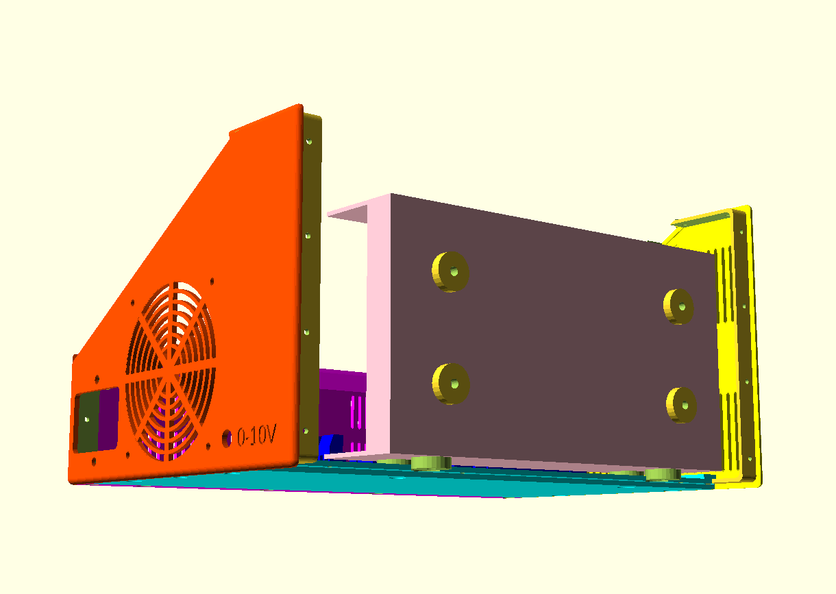
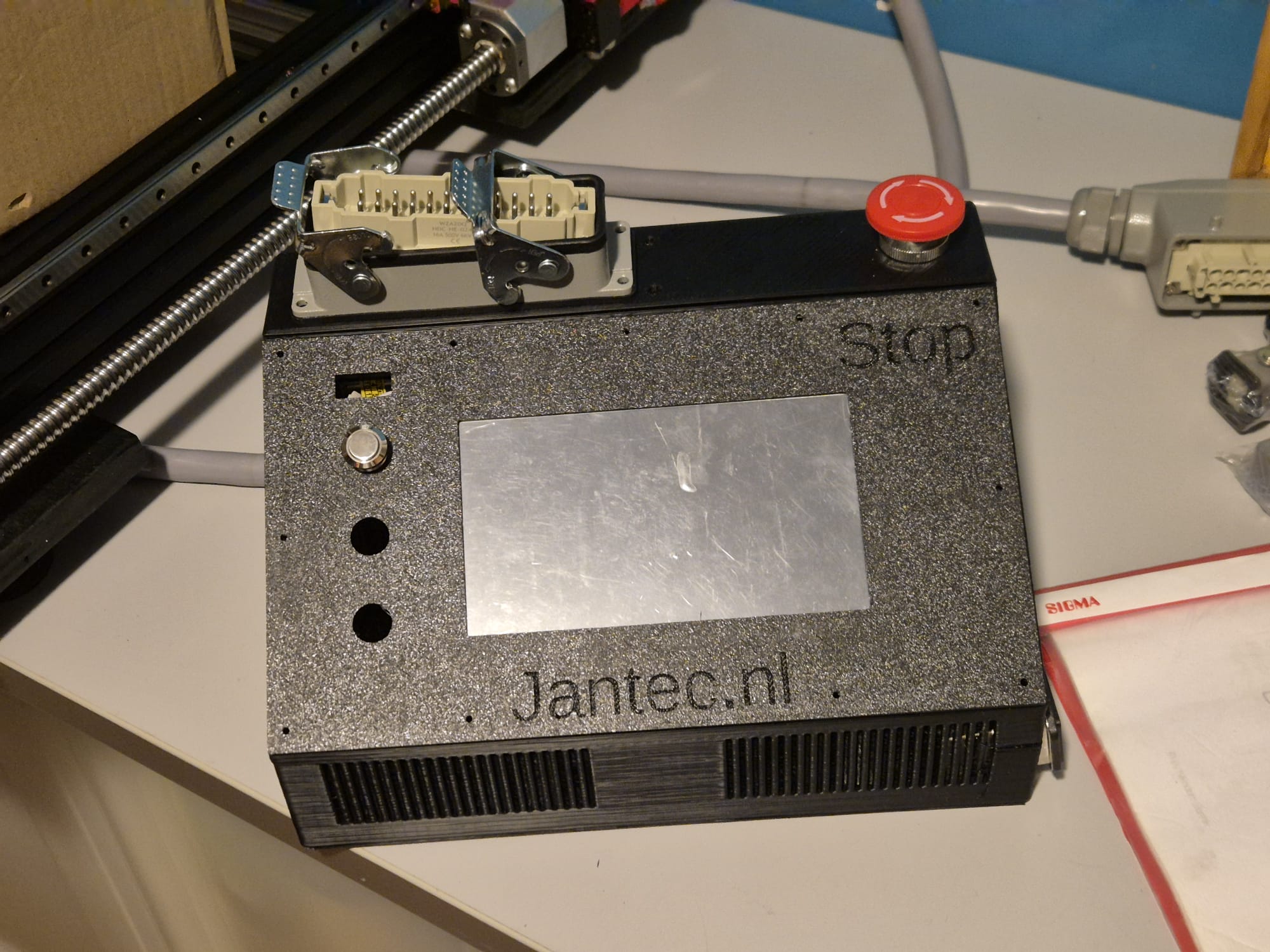
The box and panel also include holes for a 24-pins multiconnector on top, a panic button on top, an 80mm fan unit, a filtered power inlet unit (in my case, for 230V Europe standard) and 3 button holes on the tilted panel, as well as a small hole for a voltage reading unit.  Any other required holes can best be done after printing. Just with normal tools, by using painters tape first to cause minimal collateral damage to the case.

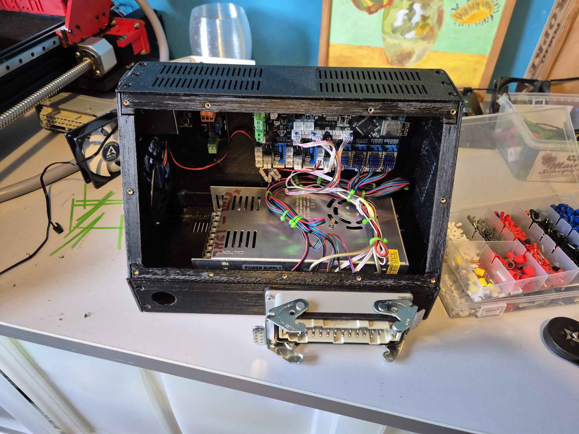
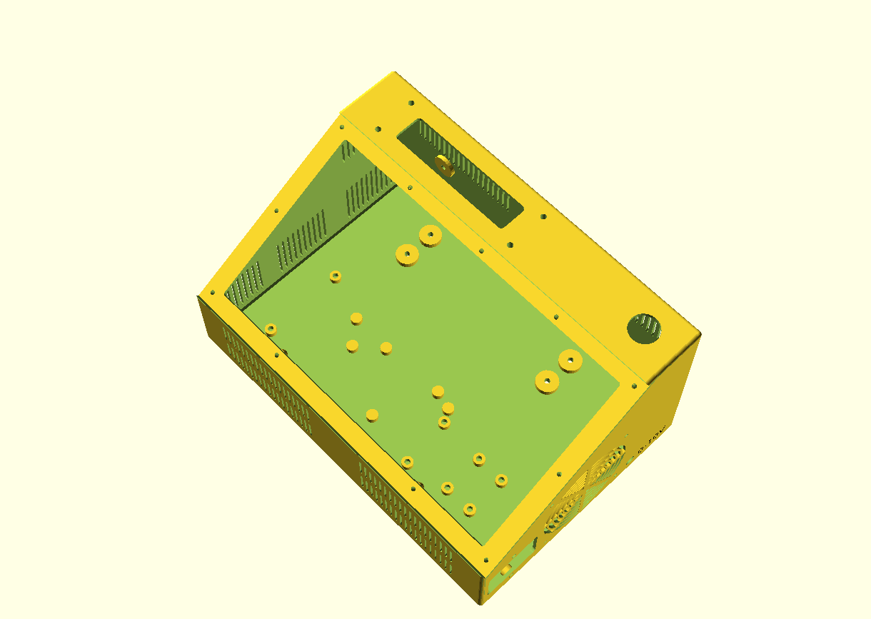
All parts that can be screwed on or-in, can utilize M3 threaded inserts at the mounting points inside. The holes are supporting these. This is not done for thePSU (obviously, the M4 mounting bolts run through the case). The fan is mounted with M3 bolts from the outside through the case and secured with nuts against the fan’s body.

CNC CONTROL BOX DESIGN, PRINTABLE IN 6 INTERLOCKING PARTS

HOW TO PRINT

I always print tools and toolcases in ABS at 260-270 degrees, 100% fan and 100% infill. .  Use minimal support of about 85% for these parts but always use maximal adhesion on the OUTSIDE only!

Also, set Cura to a shrinkage correction of 100.7%, due to ABS black shrinkage of 2.2 mm on the long side of the box. (The xSize should be 295 and this was measured 292.9 after being printed as full box)

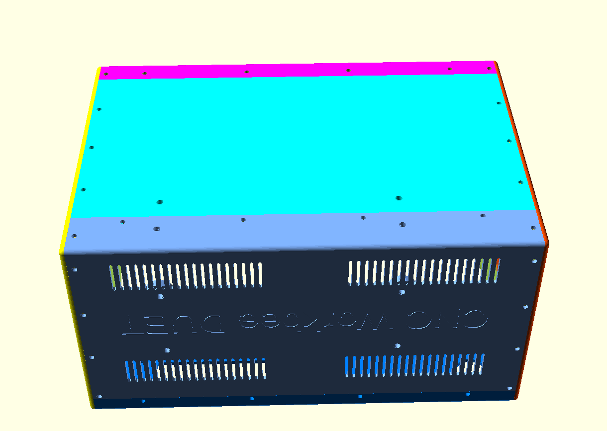
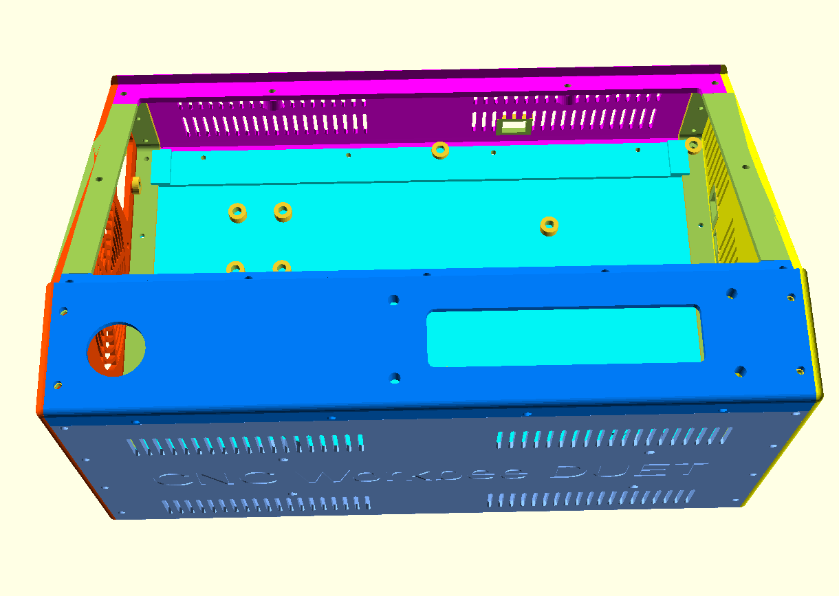
For constructing the box from 4 individually printed parts, first connect the bottom parts without glue. Then, attach both the sides and screw in the front panel. Then, where needed file or sand off ledges so it all fits properly. Then, remount it all and let the glue find its way between the connecting overlapping ledges that connect the parts.

Print all parts with the vent openings down.

All parts will print best with support 85% AND adhesion outside only ON.

Print support with 85% angle support everywhere at 5%, so the M3threaded bus-supports will be printed well.

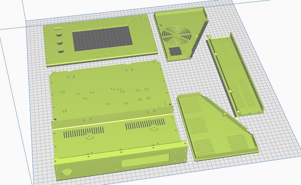
PRINT ORIENTATION EXAMPLE (Cura, VORON 2.4-600)          

Please be aware that the 6-part design is developed with printing in mind, so the horizontal printing orientation as shown above is the only way to avoid overhangs in the interlocking ledges.  This also goes for individual printing of each part.


I print this with an 0.8 mm nozzle at 0.4-0.6 mm layer height and a full print-run of all items at once still takes 1 1/2 day, at 100mms speed.

Therefore, I am now printing each part individually so I can manage it a lot better.  No fun when you run suddenly out of filament..-)

Please donate $1 to my paypal account if you use my original designs  -)

DOWNLOAD CNC_controller_box_6_parts_V2_C)JANTEC.NL_20251102

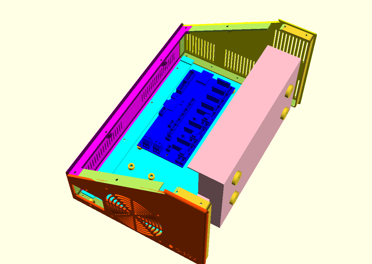
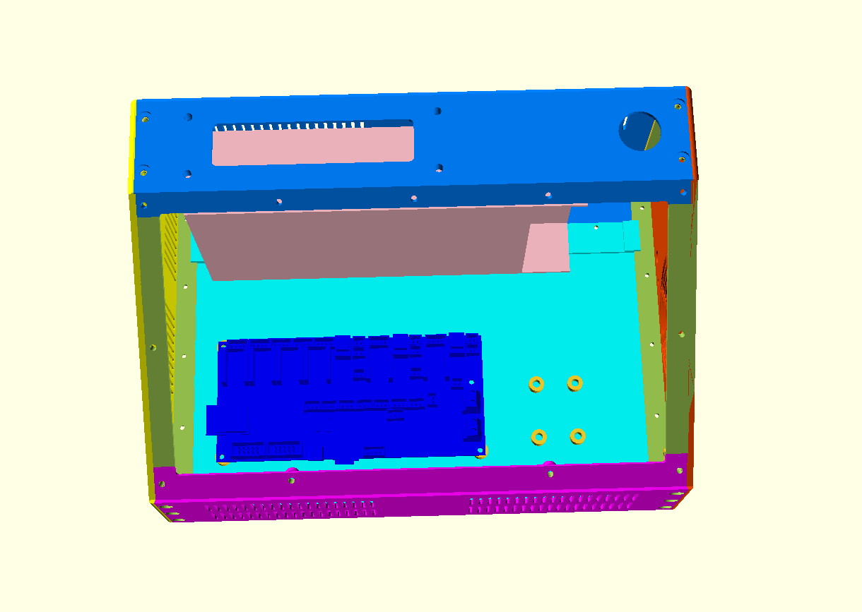
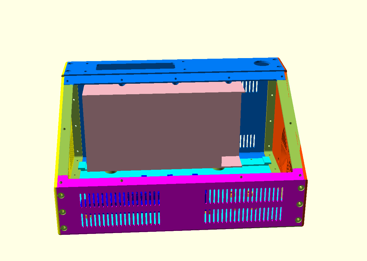
EXAMPLES WITH MOCKUP_PSU and CDYV3 board:

EXAMPLE OF A previous release PRINTED IN 1 PIECE:


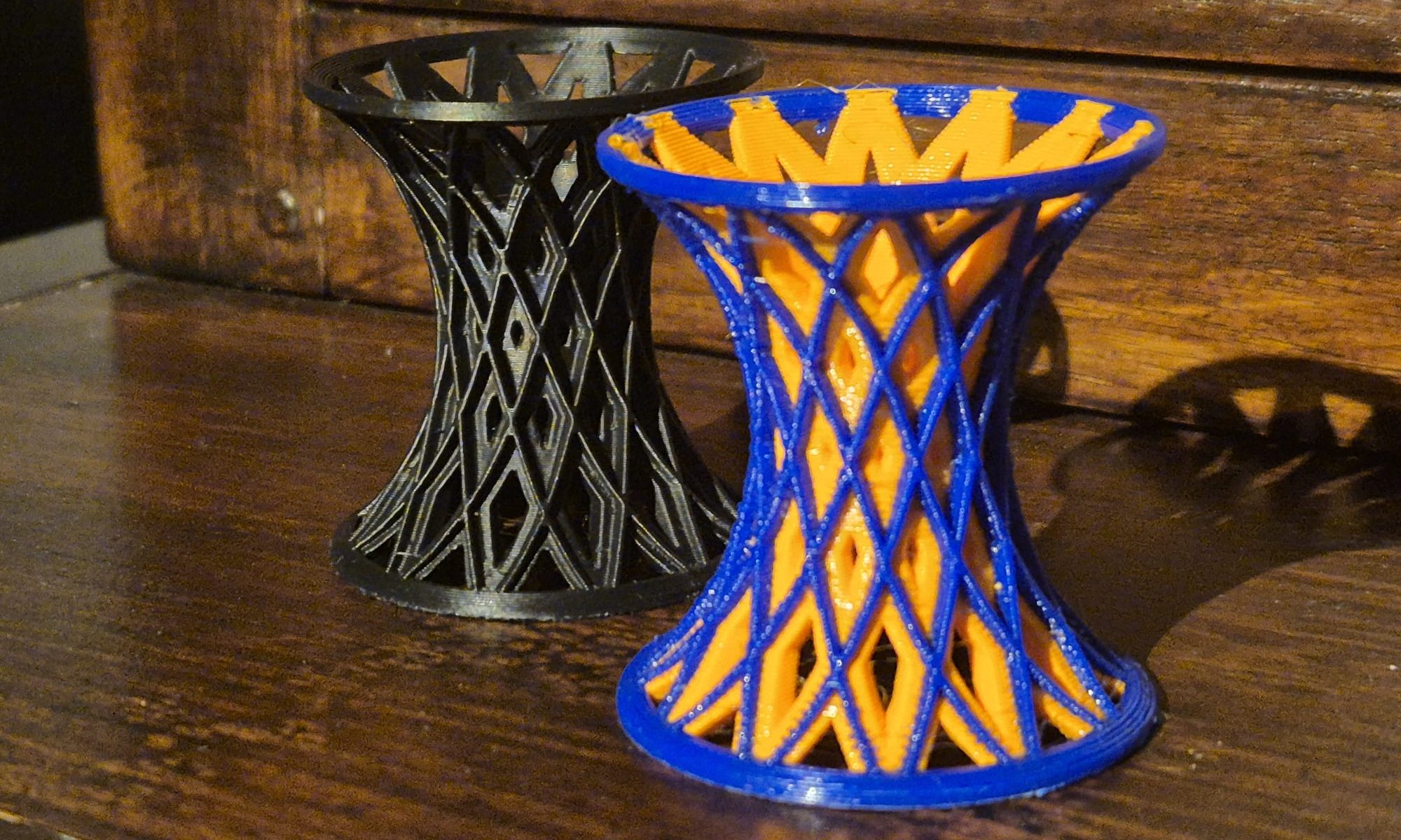
STL download single- or dualcolor articulated egg cup

COLOR1
COLOR2

Please donate $1 to my paypal account if you use my original designs !

joined colors for my E3D toolchanger
Printed this very fast with 0.3 mm LH in PLA on my E3D toolchanger
Colors combined in 1 STL
     
Printed this on my original Prusa mini in black ASA with 0.2 mm LH

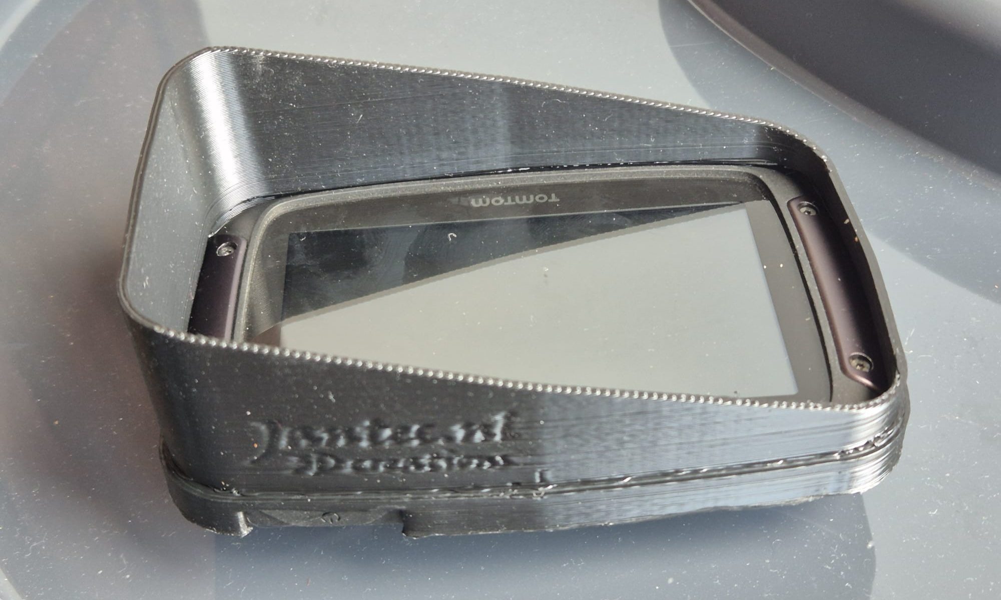
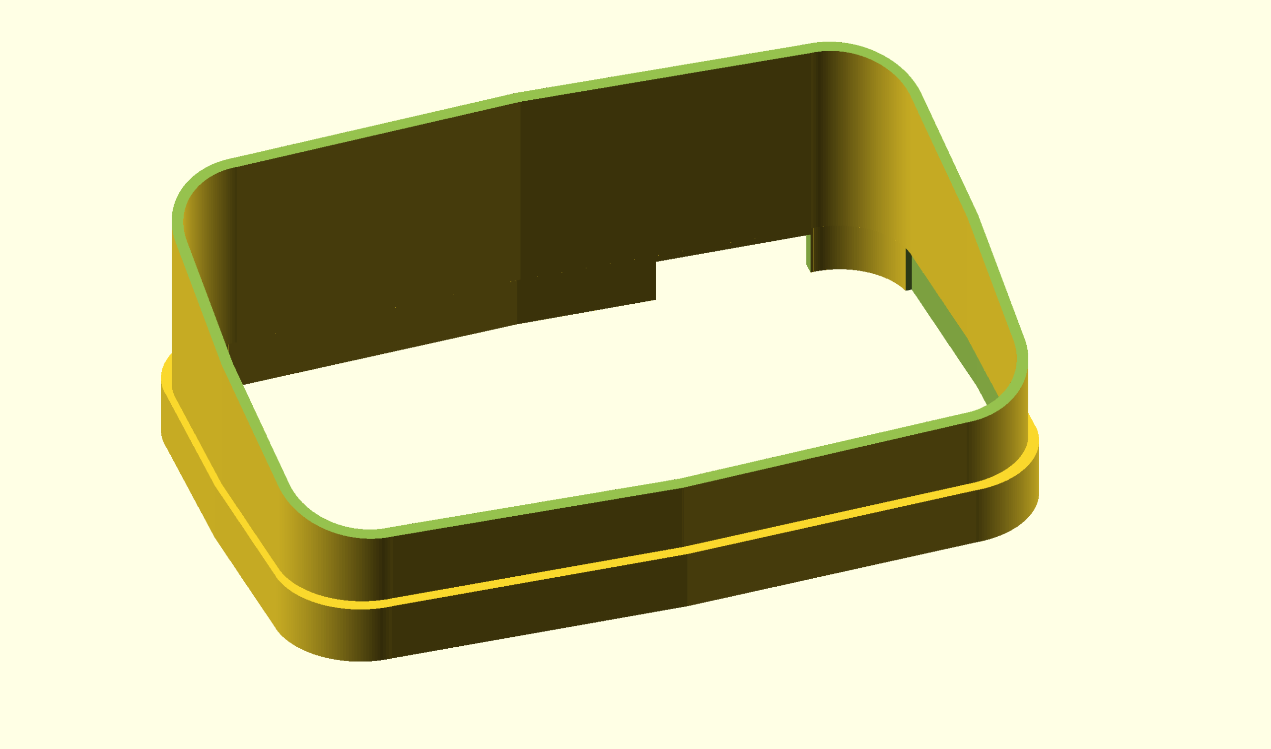
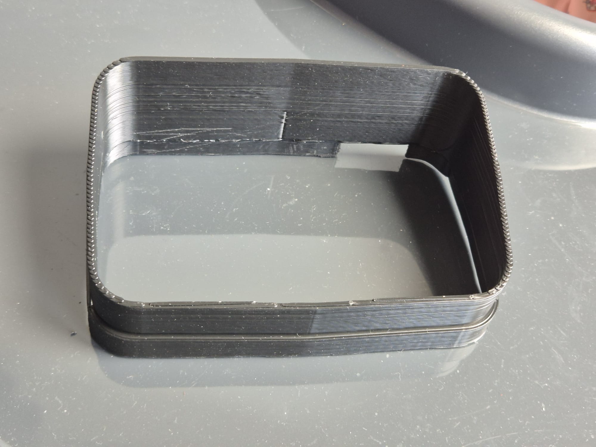
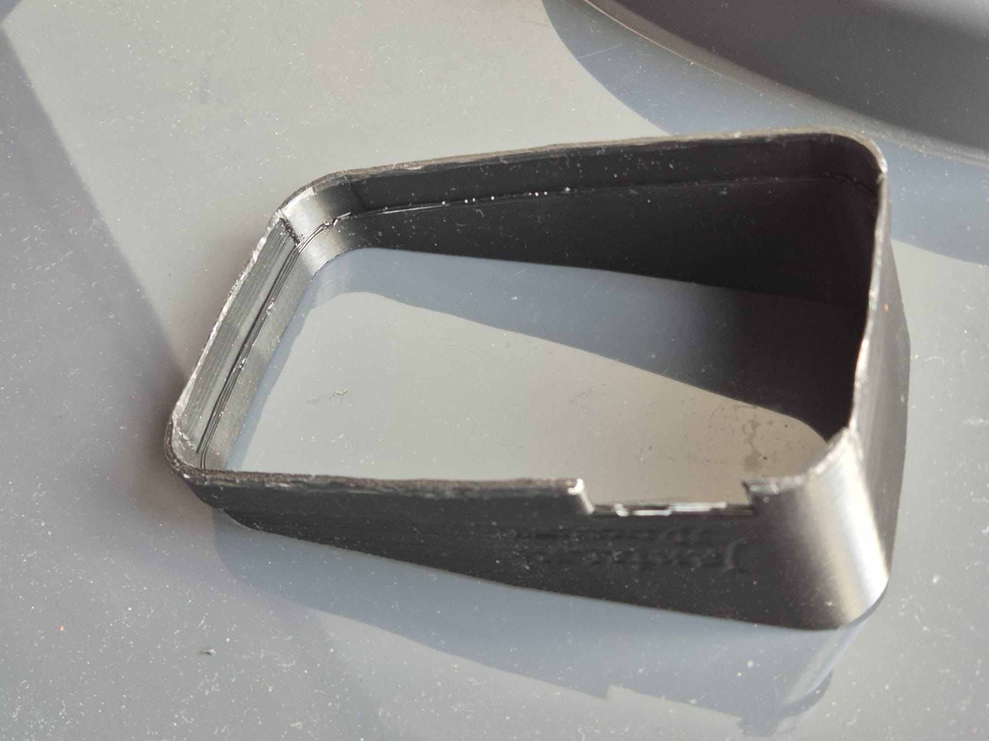
Download free vertical sun shade hood STL file for Tomtom Rider 410-550

I designed this in Openscad and it took 2 days (off and on) to get it perfect.  I started with a horizontal sun shade I designed earlier.

Please donate $1 to my paypal account if you use my original designs !

Tomtomrider550_sunshade_horizontal,_M_20251011V10


But I really needed a vertical one for usage on my motorbike.

So I changed the horizontal sun shade I had made earlier to a  vertical one, which was very easy once I had the horizontal one really perfect.  It took a couple of fitting trials before I had it good enough.

I printed this all on my hi-volume Voron600 with black ABS at 275 degrees, nozzle 0.8mm and layer height 0.4mm, 32 minutes to print the complete sun shade for my Tontom Rider 550. I always have the parts fan at 60% except 1st 3 layers and I print at 120mms, except 1st layer which is 20mms.  Travel speed is 200 mms , rather low for this print at 0.4mmLH.

I use a rather high setting for Z-hop height at layer changes because this particulat ABS filament at this temp can give a small blob at the end of print lines and I don’t want the nozzle to jam into this at layer changes.   Nor do I want to retract any more than 0.2mm since I don’t want any filament to get stuck in my so-called cold-end.

The sun shade fits snug around the Rider 550 but if you feel it is not tight enough, then print the sun shade at 99 % for the X and Y multiplier factors in your slicer.

And- yes, you should be able to print this STL file on any 3d printer with any filament and use your own preferred printer settings.

You will get much nicer prints when you use a 0.4 nozzle in your hotend and set it at 0.2mm layer height.  It will then take around 2 hours + to print.  Cheers!

Please donate $1 to my paypal account if you use my original designs !

UPDATED (nightly version)

Tomtomrider550_sunshade_vertical_L_20251011V10


Tomtomrider550_sunshade_vertical_XL_20251011V10

ABS best speed- , fan- and temperature 3dprint settings

STANDARD ABS start settings

Nozzle: 265 °C,   Bed: 110 °C

Object fan: 25% max from 5th layer,  below this: 0%

MY USAGE OF ABS

I use almost only ABS for my professional prints with an 0.6 or 0.8 nozzle.

That is because it is cheap, makes very sturdy prints and it can withstand pretty high temperatures.

I use ABS mainly for car’s interior parts, garden goodies and so on.

For any stuff that gets in cantact with food, kids and so on I use PETG.

For any other prints and all multicolor prints I use PLA.

Since I use dedicated printers per type of filament, I hardly ever have clogs or ruïned prints.

ABS- my story

Actually, there is not one standard for ABS settings. That’;s due to the fact that not all ABS on the market is really the same type.

However, I can give you some hints for different types of ABS 1.75 mm filament, after my extensive experience with those specific types of filament.

DO PRINT MY TESTPIECE PRIOR TO PRINTING ANY OBJECT and inspect the brim, and the sturdiness of the wall adhering, and the layer adhering.

Regular ABS: nozzle temp 270 deg C (15 deg too low), bed 120 deg C, object fan 30% (should be 0%) , 0.8 nozzle at 0.4 mm Layer Height, printing speed set to 120mm/s, BIG BRIM everywhere, brim also at LH 0.4mm, line width set at 0.8 exactly, sliced all in Cura

DOWNLOAD JANTEC.NL’s TESTPRINT_tilted_raster_20250902V1_STL

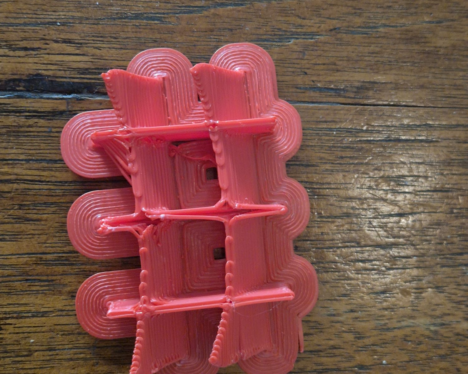
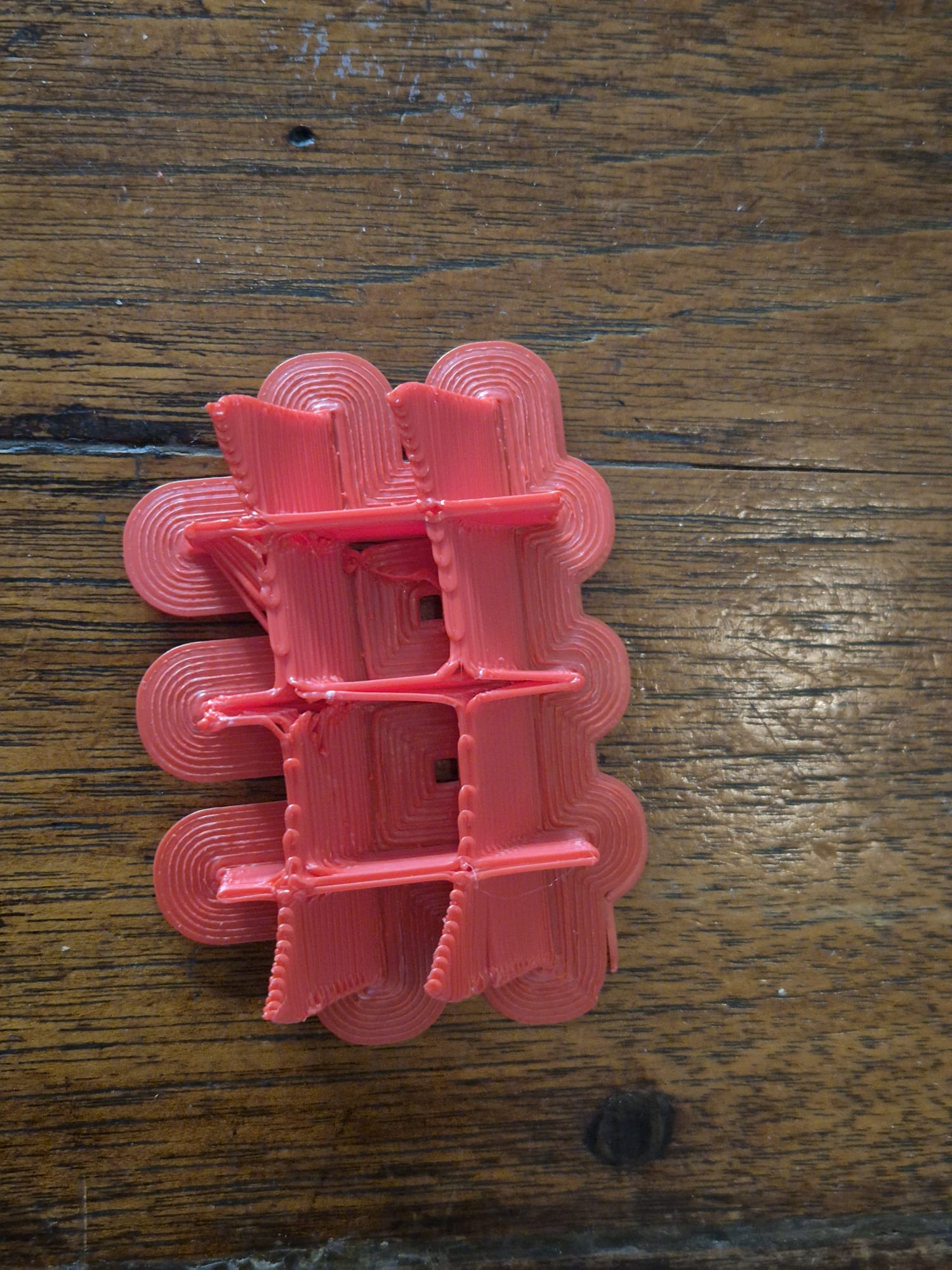
If the print comes apart if you try to break it at low force like in the above picture, the print temp is too low. Same for the wings of the testpiece as for layer adherence.

If you observe a bubbly surface, your ABS is wet.  It will probably not be able to save it.  You can try to dry it in an oven or in a food dehydrator at 80 degrees C, for at least 10 hours.  My experience is that this is a waste of time and energy.  Just throw it away in the plastics recycle bin.

GENERIC ABS PREREQUISITES

  1. For all ABS, you need a hotbed at at least 90 degrees C but 120 deg C is better;
  2. You will also need a hotbed plate with either a layer of smooth PEI on it, OR a hotbed plate with textured PEI, which I use especially for my 0.8 mm nozzle prints.;
  3. In general, never ever use a toolfan.  Unless you are using low-temperature ABS like EASY ABS with the rquired lower bed- and nozzle temperature settings;
  4. Always use a completely covering enclosure for your printer;
  5. Always do a bed mesh that really works prior to printing ABS and make sure this is done at operating temperatures of both bed and nozzle;
  6. Print with a really big brim everywhere, at least 10 lines wide, also for your support structure;
  7. Print the first layer with at least your regular print temp, NEVER any lower;
  8. NO object fan on first 4 layers!

SUNLU ABS (WHITE AND BLACK)

Sunlu has ABS filament that is shiny on the spool, and can be printed shiny at the right temperature.  This filament is not very prone to warping.

Nozzle: 265 deg C

Bed: 120 deg C

Object fan: 30% max=regular, no object fan on first 4 layers

EASY ABS (RED)

This ABS is also shiny, makes very sturdy prints and needs lower temp than general ABS. And- it requires a bit of object fan speed. The prints come out shiny. This type of ABS is not at all prone to warping, as far as I experienced.

Nozzle: 235 deg C

Bed: 90 deg C

Object fan: 60% max=regular, no object fan on first 4 layers

GENERIC ABS (RED, matte)

This is the most difficult to print matte red ABS(on the spool)  and requires very high printtemp, and can’t handle any percentage of object fan.  The prints come out matte when printed under 270 degrees and at 285 deg they are shiny.  This type of ABS is very much prone to warping.  This is likely a type of ABS without any additions to it.

Nozzle: 285 deg C

Bed: 120 deg C

Object fan: 0% max=regular, no object fan on first 4 layers

garden wall with 3d printed hanging flower pots download free STL files

In my small garden, a wall from my neighbour’s house extension has always felt a sort of in my way.  I thought a lot about making this wall a bit more visually attractive and I came up with this:

I created a setup with impregnated wooden garden planks, which I splitted lenghtwise with my small portable sawmill.  The wood carries around 20 small 3d-printed flower pots in all sort of colors and shapes.

In the flower pots, I  put in a variety of small plants plants of which most of them can withstand the Dutch winter time, so I don’t need to replace all plants next year.

Also, I put in an automated solar-powered watering system that utilises my rain water gathering supply bins.

I am very happy with the result!

Below in this post I have gathered my flower pot designs for this wall, if you click the images, the STL file will be automatically downloaded to your device.

Cheers! Jan, 08-2025


square_plant_hanger_b100xd100xh110_V12_REVd_20250702 square_plant_hanger_b220xd80xh80_V12_REVd_20250701 square_plant_hanger_b80xd80xh100_V12_REVc_20250701 Diagonal_plant_hanger_T110_B90_H125_V2_20250701 Square_diagonally_placed_plant_hanger_TOP110_BOTT90_HEIGHT225_V1_20250630

Facets_semi_round_plant_hanger_TOP260_BOTT170_HEIGHT220_V15_20250628c


Please donate 1 US Dollar to my paypal account if you use (parts of) my developed materials so I can continue to share nice stuff for you to download

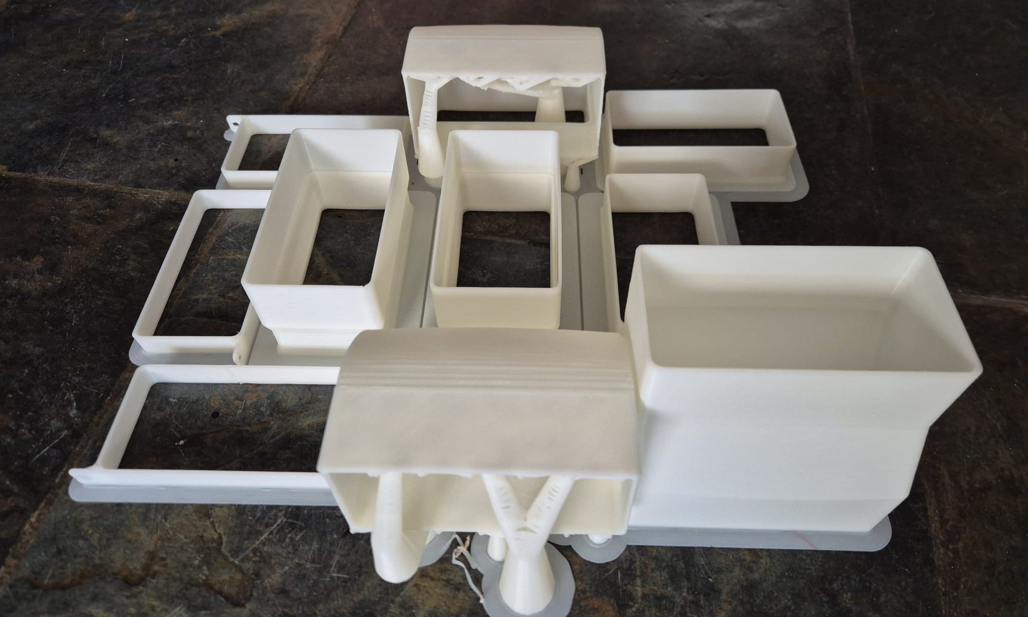
FREE STL DOWNLOADS reducers, bends, offset pieces, mounting brackets and wall bushings for 55×110 mm air ducts

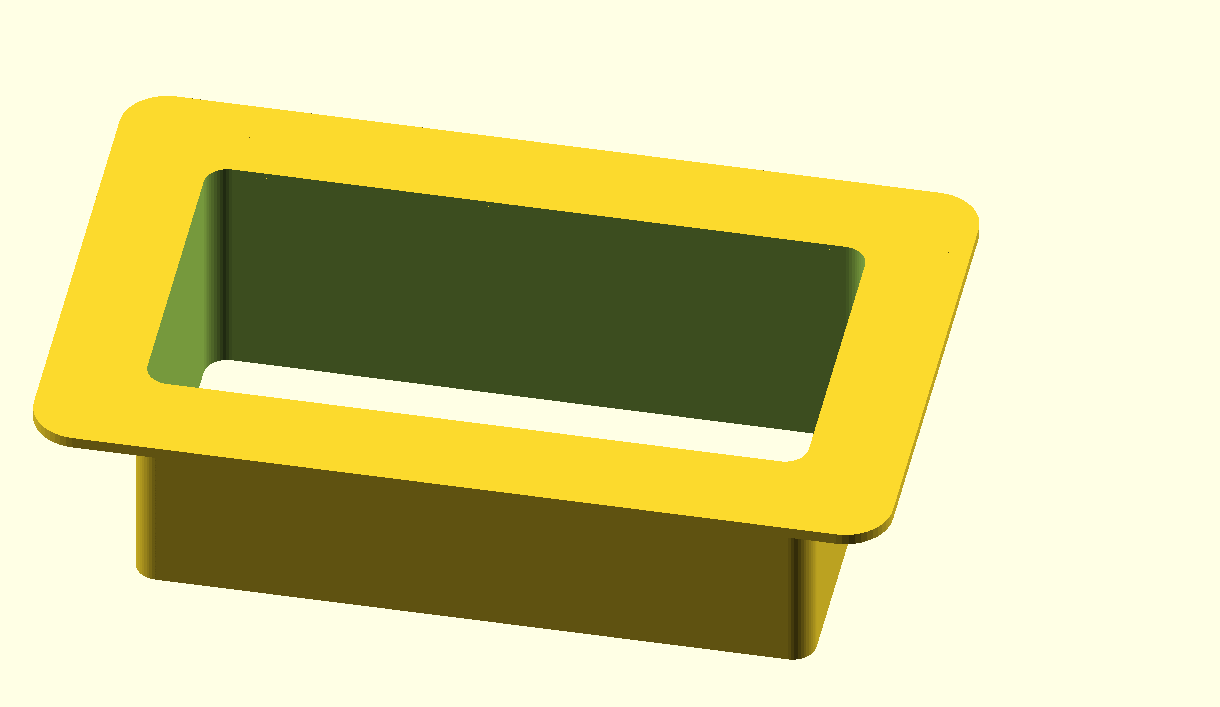
10mm wall plate for 55x110mm air duct. The wall plates are glued in place in the wall and are also used for  covering the sides of the through-hole in the wall. The 55×110 air duct will then pass through the glued-in wall plates on either side of the wall.

40mm wall plate for 55x110mm air duct.
wall_plate, extended to 60mm for 55x110mm air duct. This piece connects through the wall  and fits in one of the above wall plate-pieces
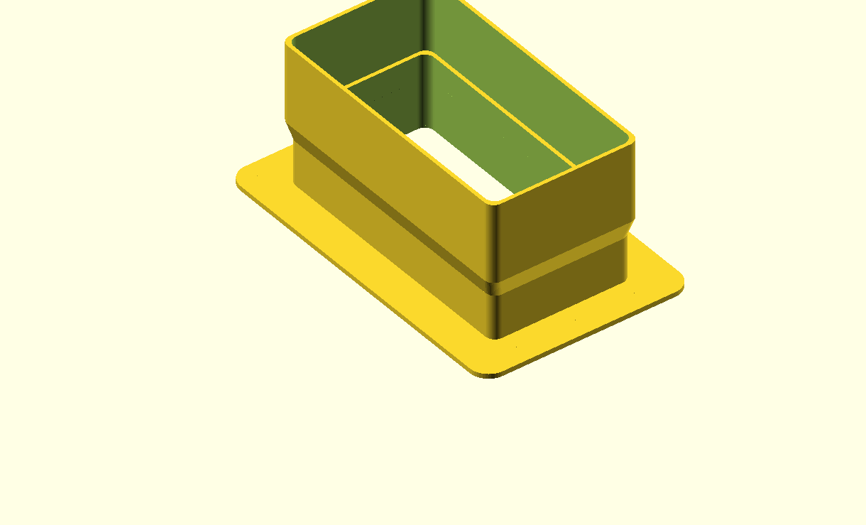
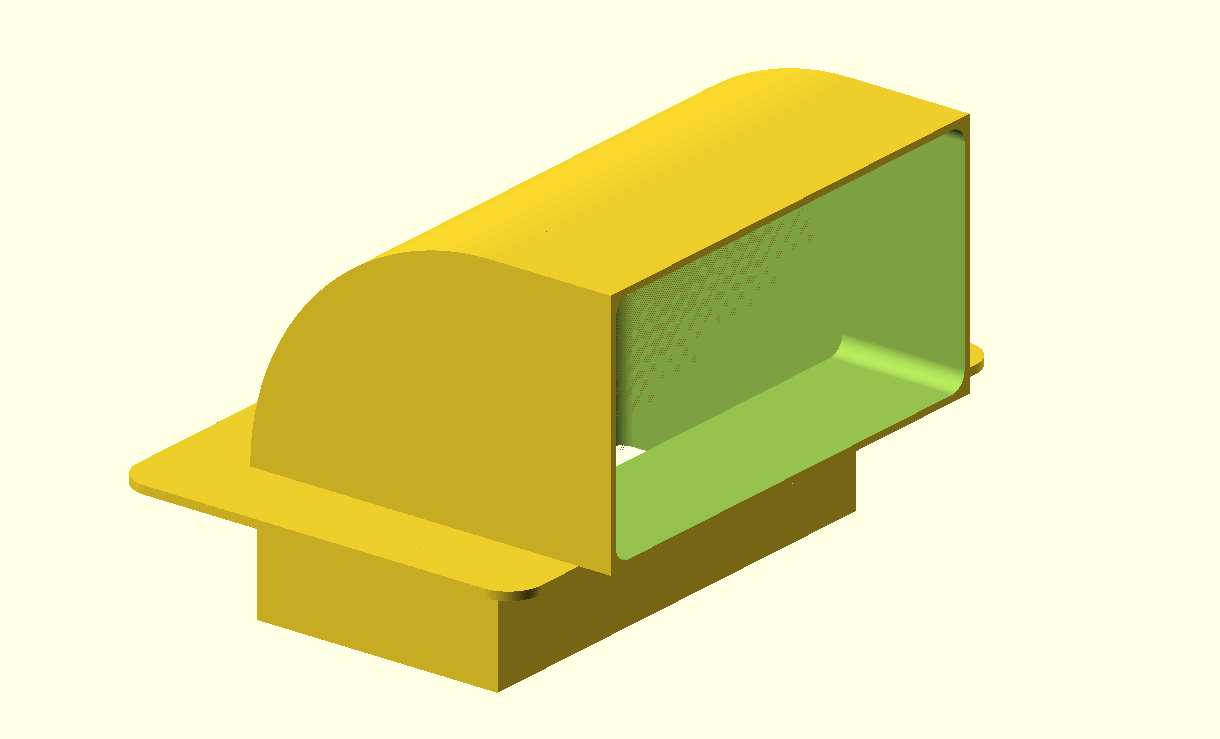
wall plate with short 90 degrees angled bend. Both sides connect to a 55x110mm air duct


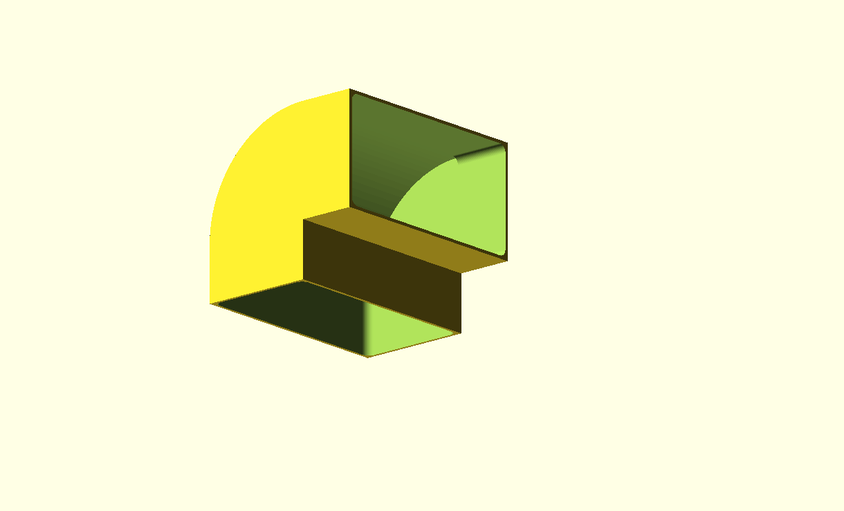
90 degrees bend for 55x110mm air duct
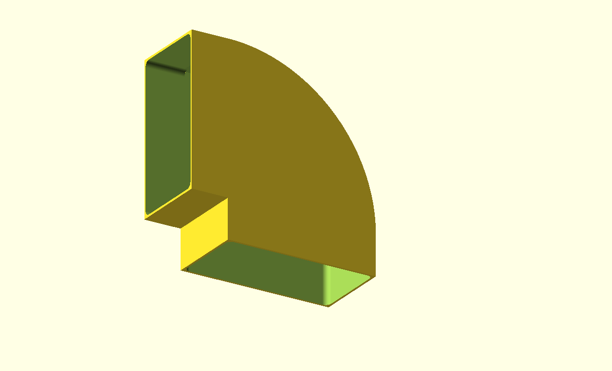
90 degrees bend for 110x55mm air duct
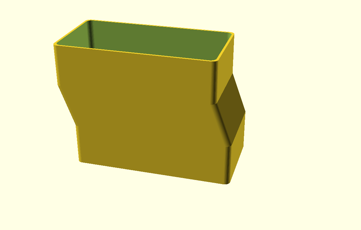
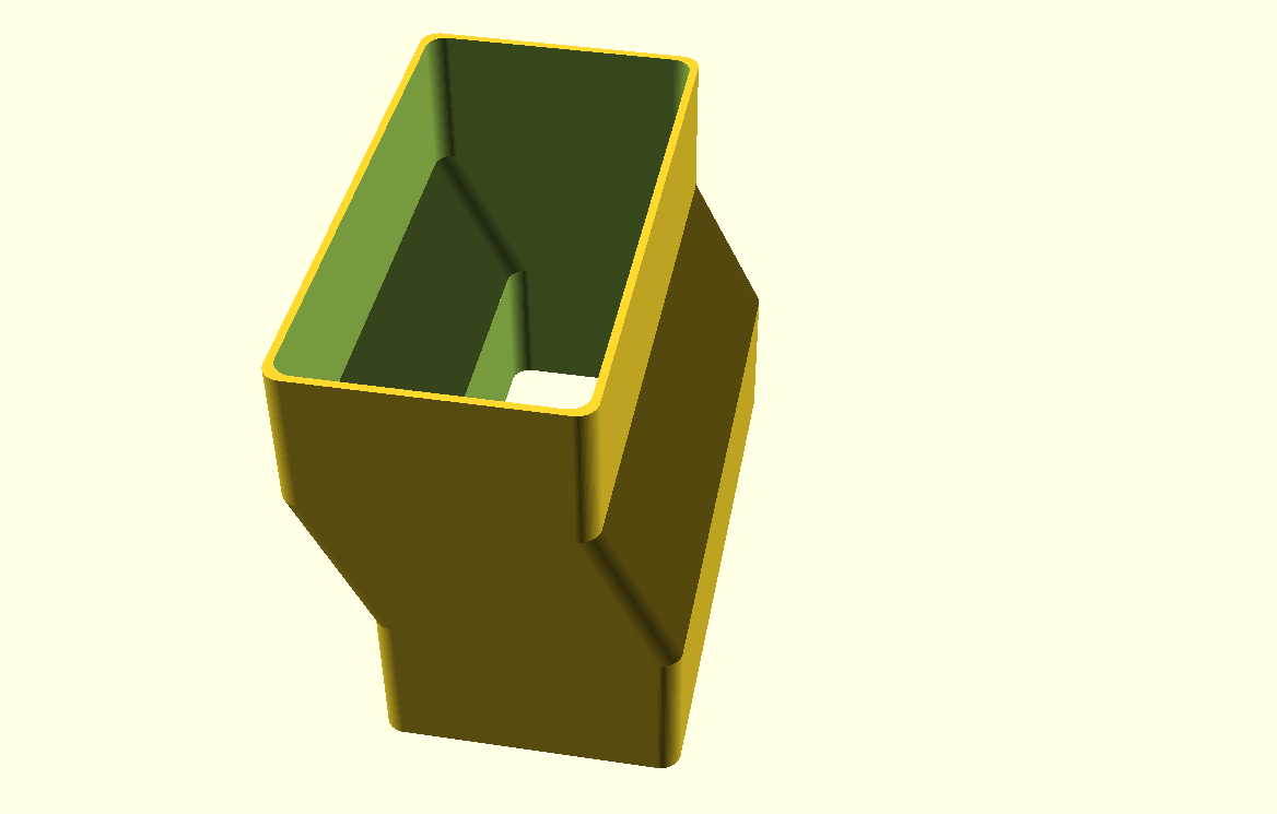
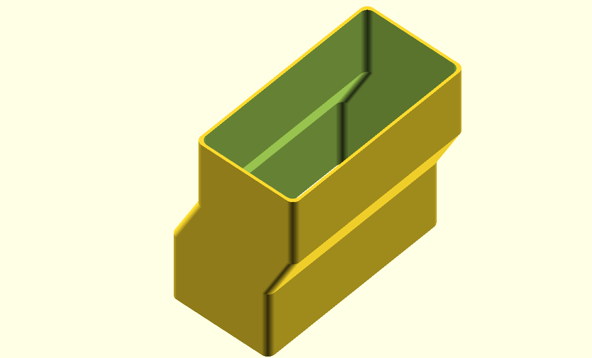
pipe connector piece with 15mm offset, both sides connect to a 55x110mm air duct
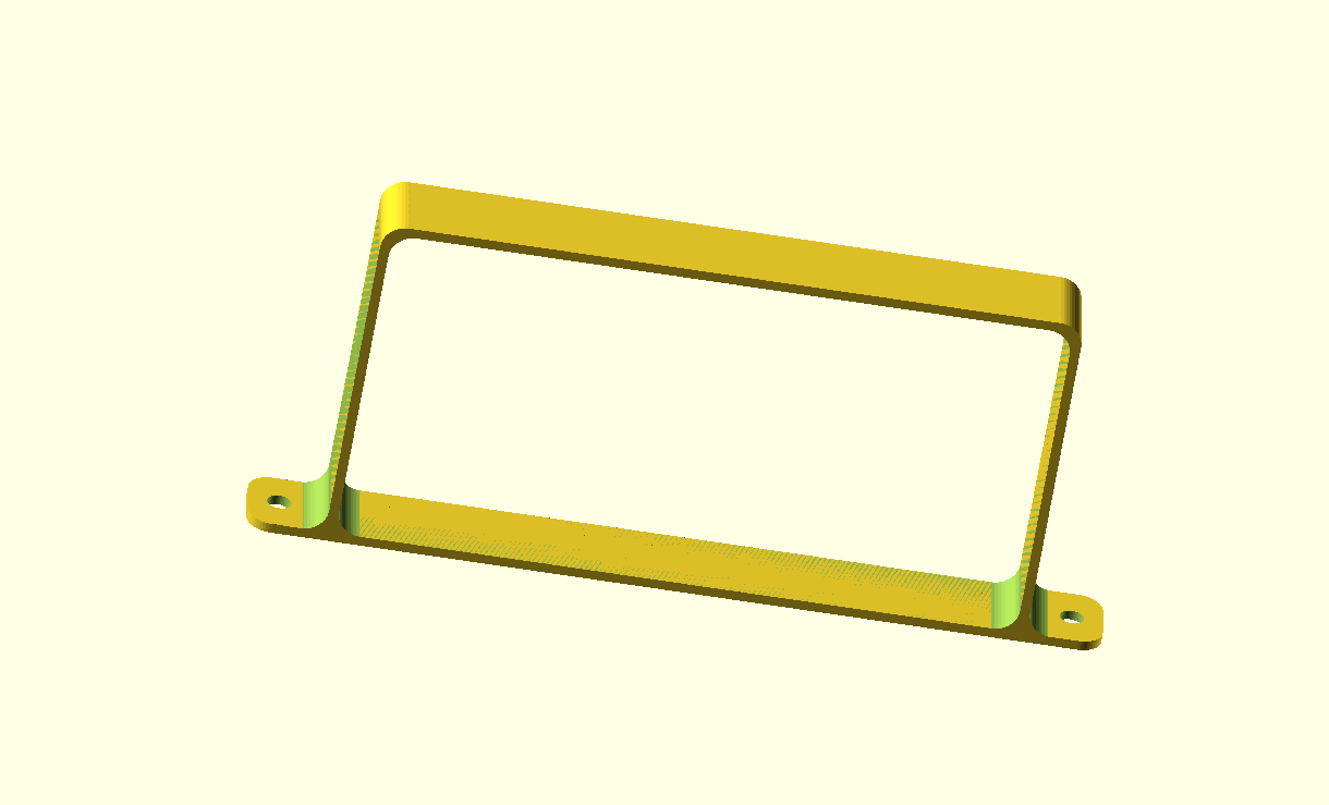
slim mounting bracket for 55x110mm air ducts


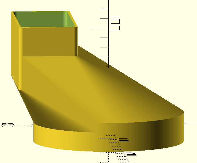
transition piece from round 150mm air filter box output to 55x110mm air duct, wall_mounted
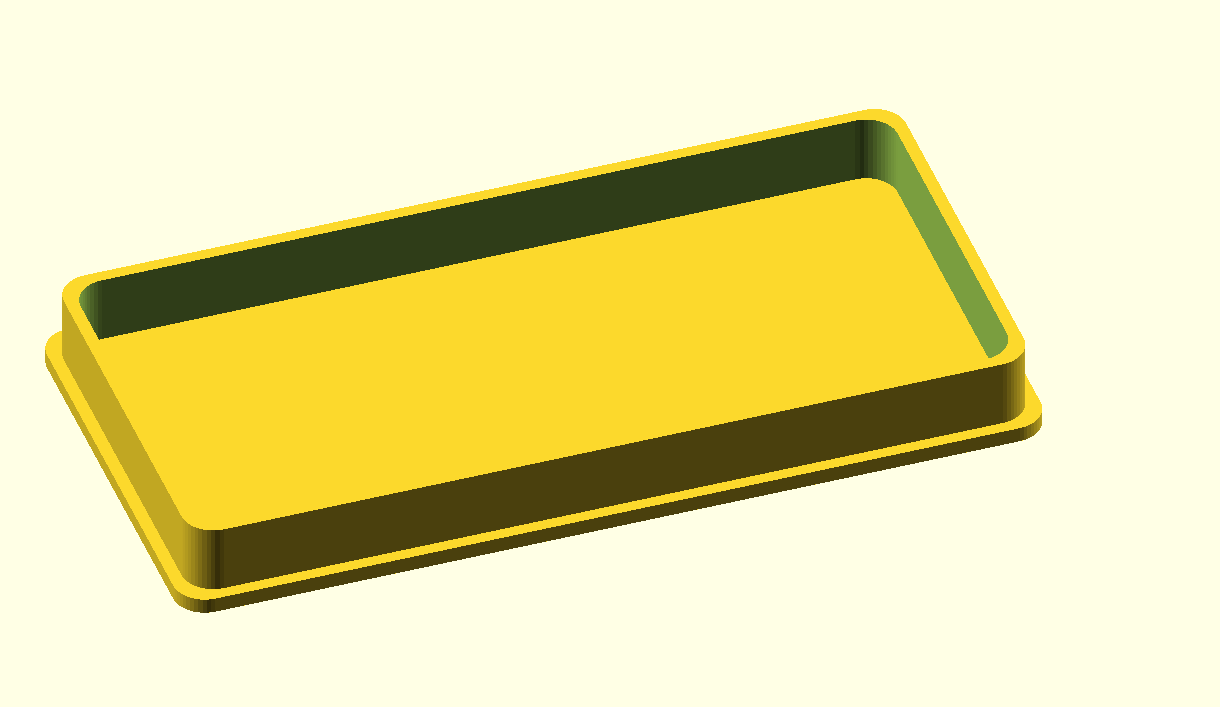
endcap for 55x110mm air duct


CNC workbee control cabinet free OBJ and STL downloads with space for DUET3 6HC, power supply, panic button, 24-pin multi-connector and Fysetc 7-inch Duepanel touch-LCD

Due to the DUET3 control board’s size, it does not fit into the previously developed CNC housing for a FLY_CDY board, so a lot of modifications had to be made.  This resulted in the preliminary (V13) OBJ design which can be downloaded HERE (20250604)

This post has the published  last version with tight fits for the DUET3 6HC motherboard, the 24V PSU and so on.

The dimensions of the newer DUET version are smaller than the peliminary DUET3 version. Now, the dimensions are made the same as the CNC controller box that I made earlier for the Mellow FLY CDY2 or -3 motherboard and DUET Workbee, DWC LCD controller from FysetC and so on.

By now, I also have a workable 7-part release for this DUET3 6HC CNC controller box.

To print this 7-part version, you will need a 3D printer that has a minimum 300 mm span width of it’s printbed.

I found it a lot easier to print the controller box in 7 separate parts than in one big  print-run for just the box of around 1 1/2 day which uses 940 grams of filament.

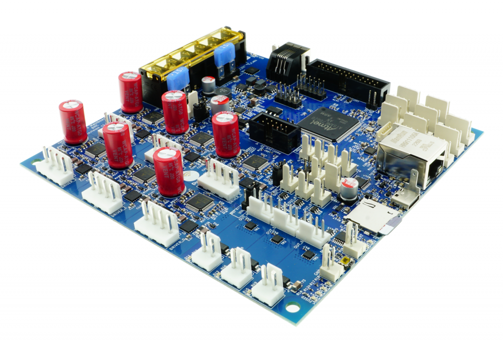
DUET3 6HC motherboard

The box and faceplate for DUET3 6HC is available as:

  1. The old preliminary (V13) OBJ design HERE (20250604)
  2. The LAST available STL is available below for the BOX in 1 piece

CNC_controller_box_simplified_1_part_V20_FINAL_MOTHER_DUET3_6HC_BOX_ONLY_C)JANTEC.NL_20251108

3. The last available STL for the FYSETC 7 inch DWC font panel is below:

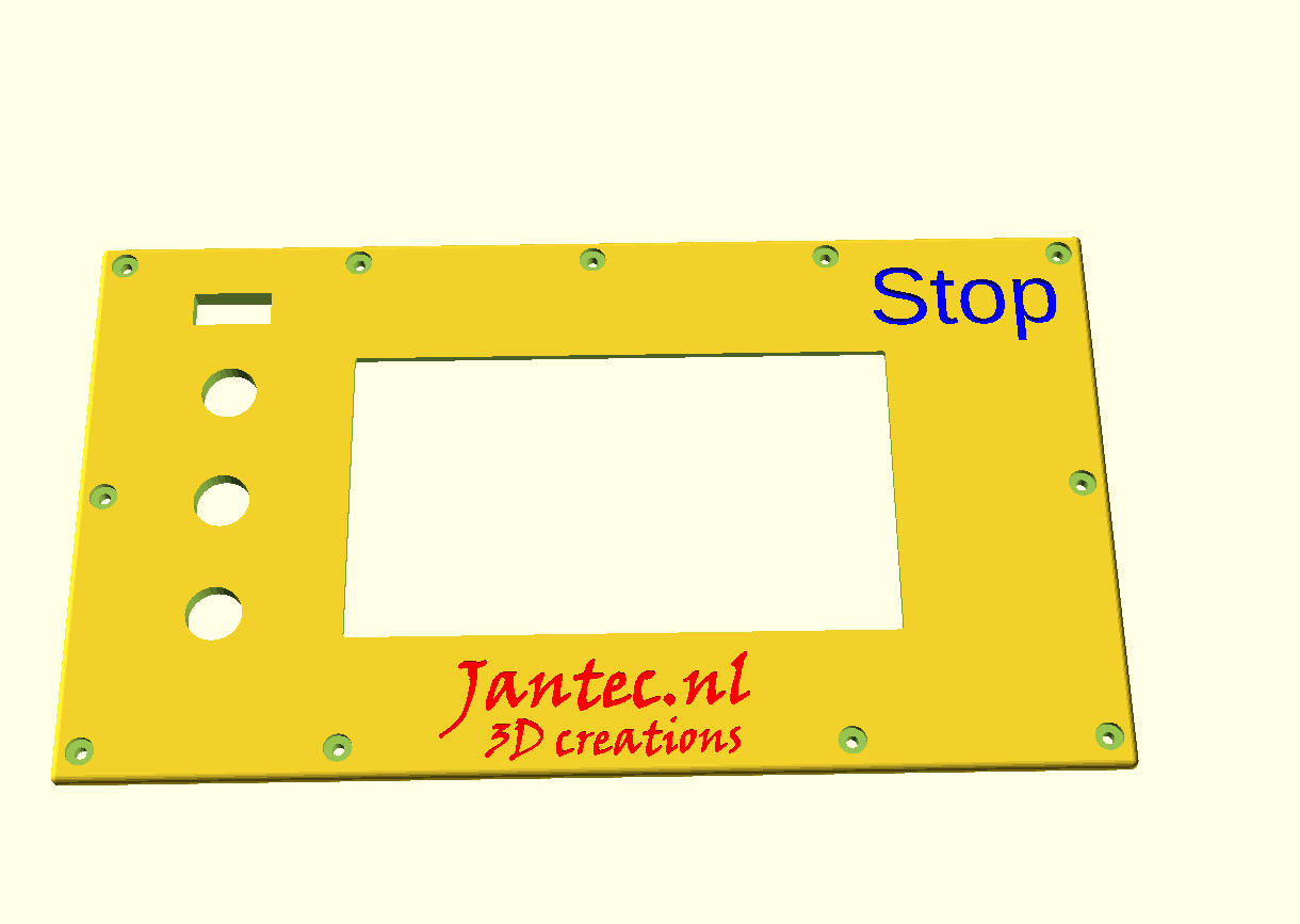
CNC_controller_box_simplified_1_part_V20_FINAL_MOTHER_DUET3_6HC_FYSETC_FRONT_ONLY_C)JANTEC.NL_20251108

SHOWN WITH MOCKUP PARTS INSIDE:

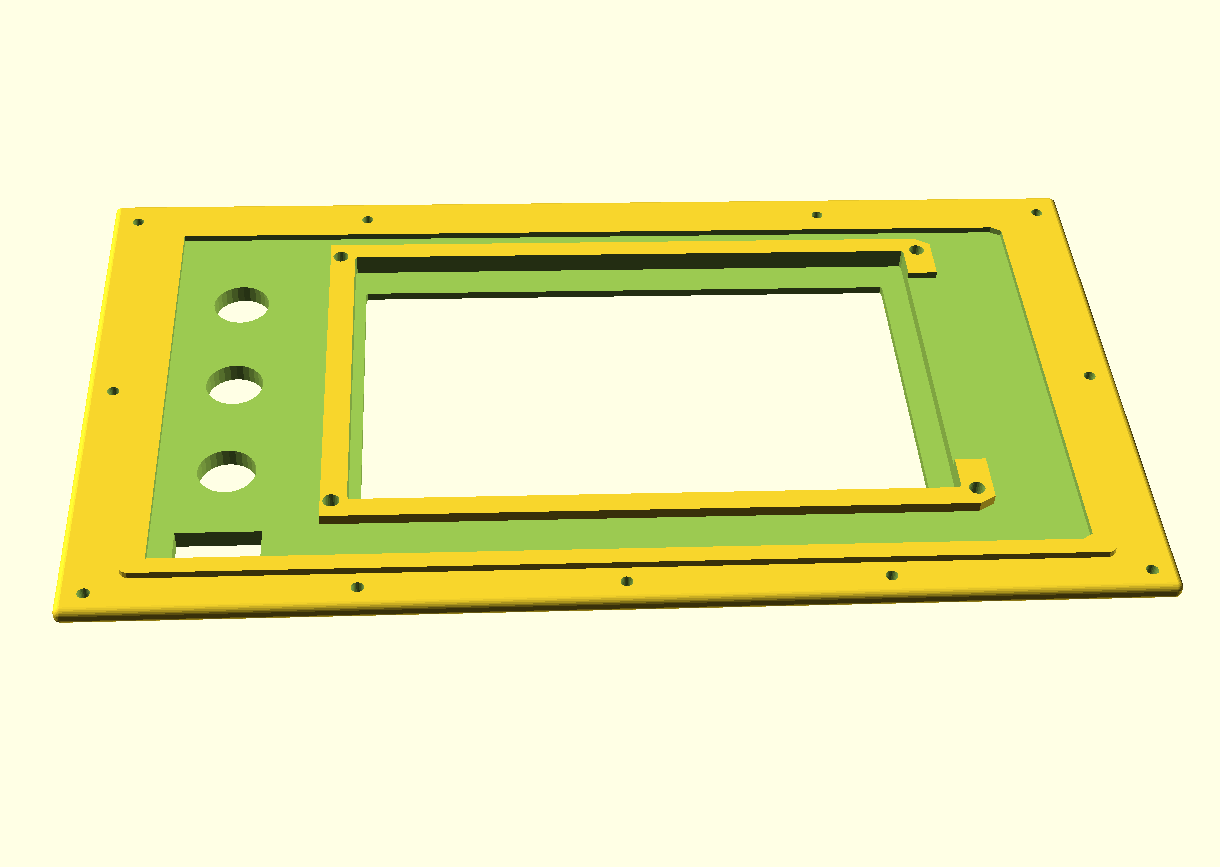
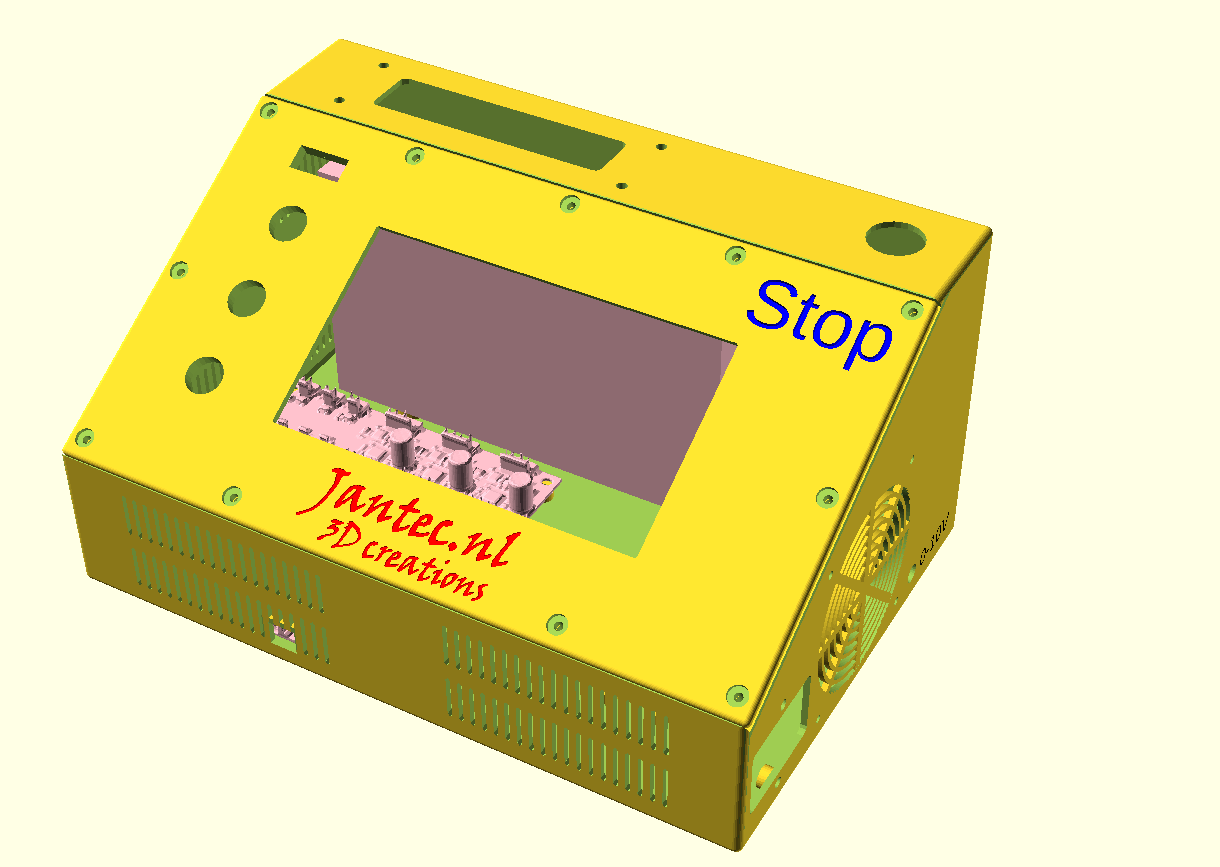
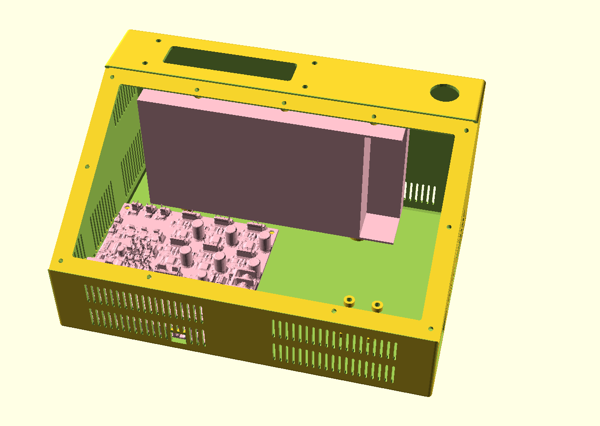
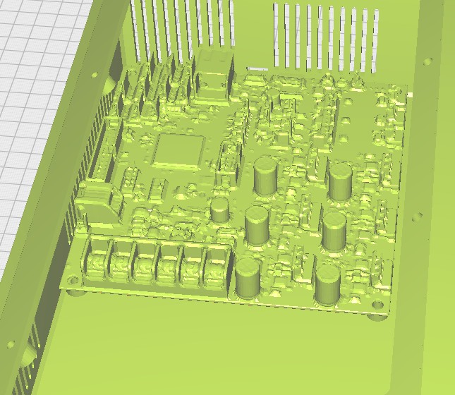
Version V20 of the Duet3 6HC CNC controller box with mockups inside and FYSETC 7 inch LCD DWC mounted, 2025Nov08

Please donate $1 to my paypal account if you use my original designs  -)

The old preliminary larger version of box and front panel, which is also OK


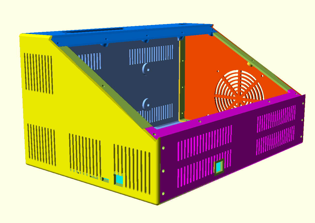
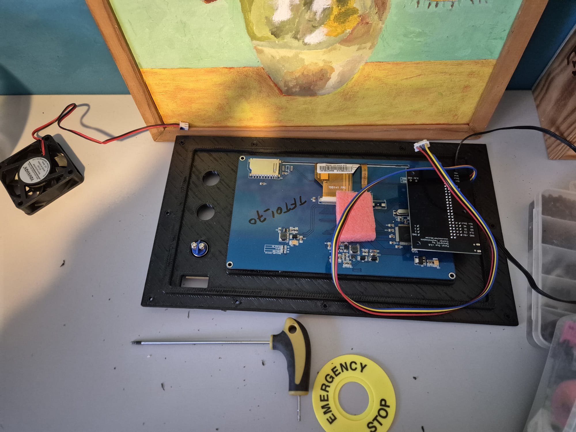
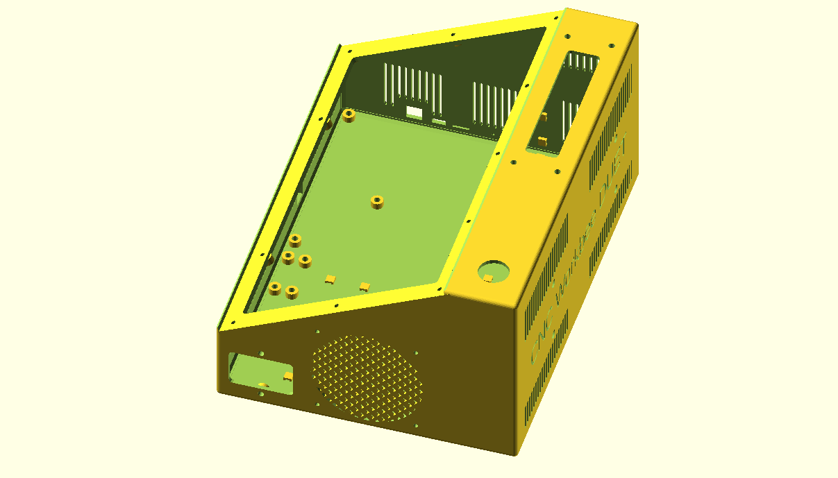
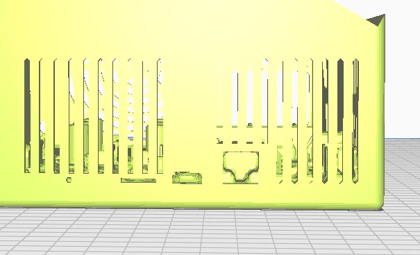
Side view of the CNC workbee DUET3 enclosure, with the cutouts for the reset, microsdCard, USB and Ethernet connection visible below, left of centre. The canbus connection can be seen at the front of the enclosure, at the bottom.
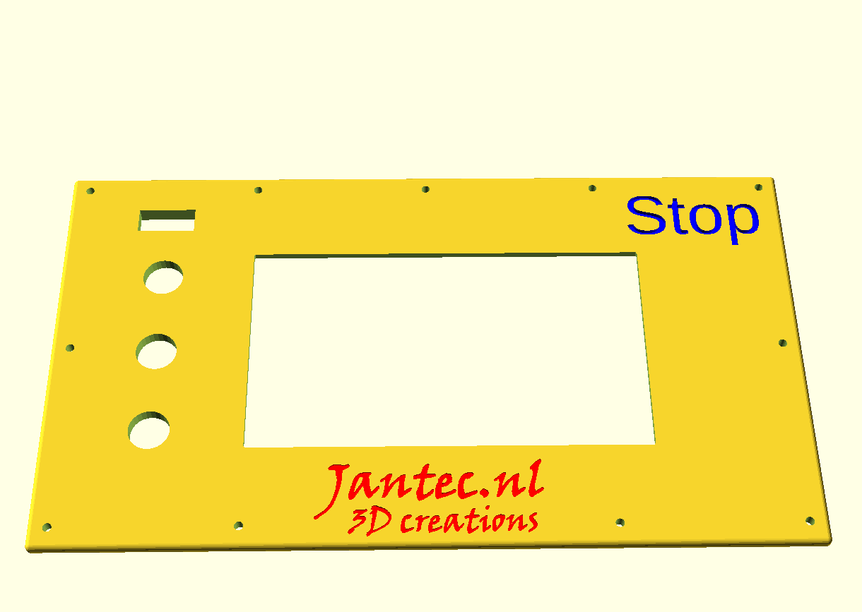
Side view of the preliminary version of the CNC workbee DUET3 enclosure, with the cutouts for the reset, microsdCard, USB and Ethernet connection visible below, left of centre. The canbus connection can be seen at the front of the enclosure, at the bottom., This is the old version which has the same dimensions as the V20 version but has the old JANTEC.NL text on the LCD front panel


TOP view of the CNC workbee DUET3 housing, with the cutouts and attachment points for the threaded inserts visible at top left
TOP view of the old CNC workbee DUET3 housing, with the cutouts and attachment points for the threaded inserts visible at top left
The V20 new version with PSU and DUET3D-6HC mockups inside for position examples
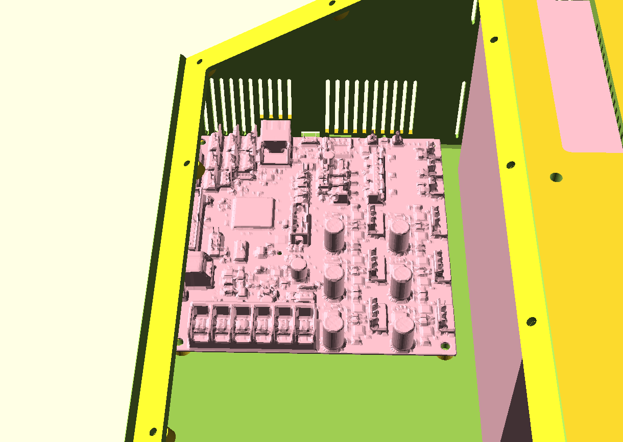
This pictures shows in detail the tight fit of the new  BOX’s version where the DUET3 6HC board is shown against the inner box’s walls. This is required for utilizing the board’s external sockets through the BOX’s outer walls like ehternet, canbus, reset, SDcard
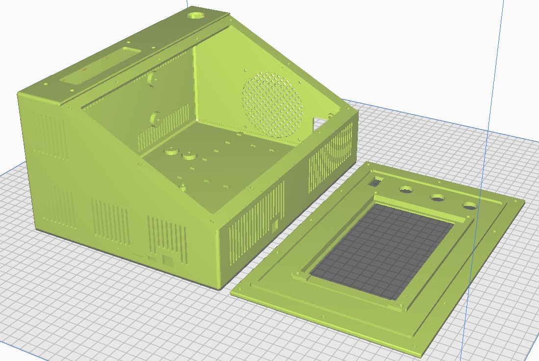
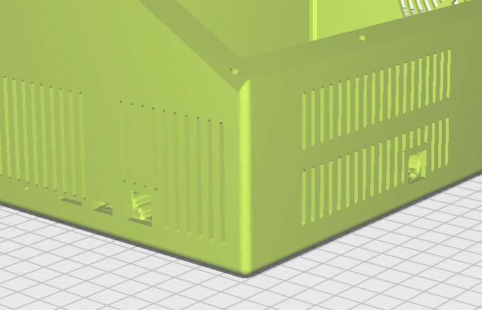
Slicer’s result with mockups inside, this shows the in/outlet ports, reset, usb access port, cdcard access


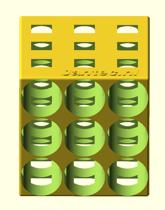
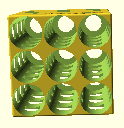
Free STL download fridge beer bottle organizer by Jantec.nl


Rear/top view

Front view

fits regular beer bottles of 330cl

//length regular beer bottle of 330cc is 238mm
//diameter regular 330cc beer bottle is 61mm

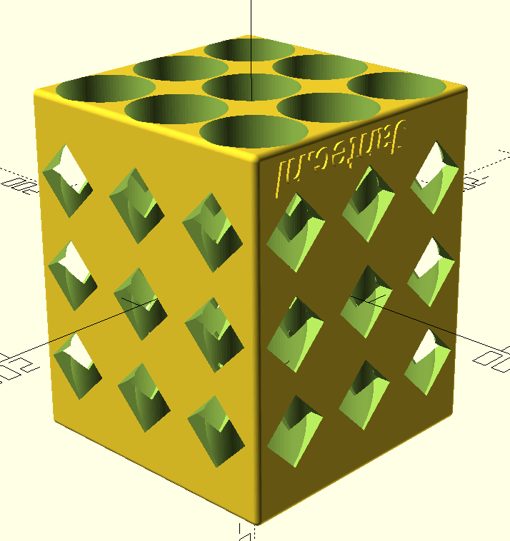
The beer bottle box in 3×3 bottles version measures 238 mm deep and  197mm wide & high.

beer bottles 3×3 fridge rack 2023 04 20


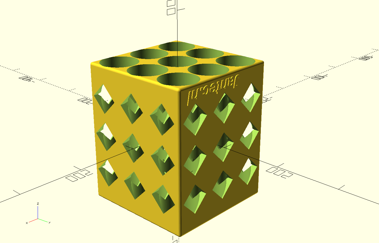
And a revised version that can be printed without support:

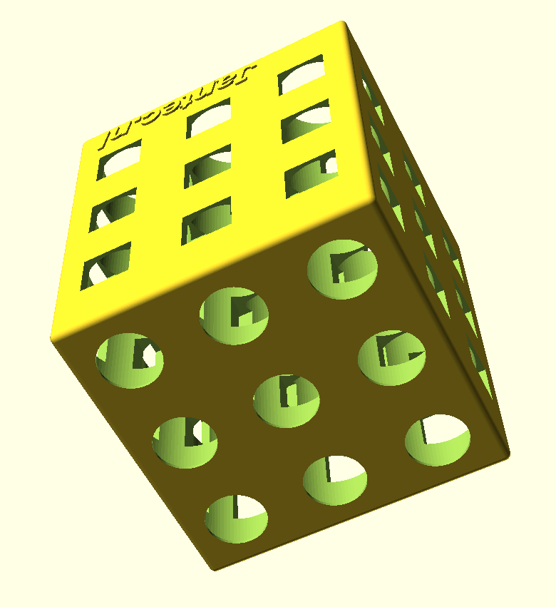
beer bottles fridge rack with 45deg squared side holes 2023 04 20


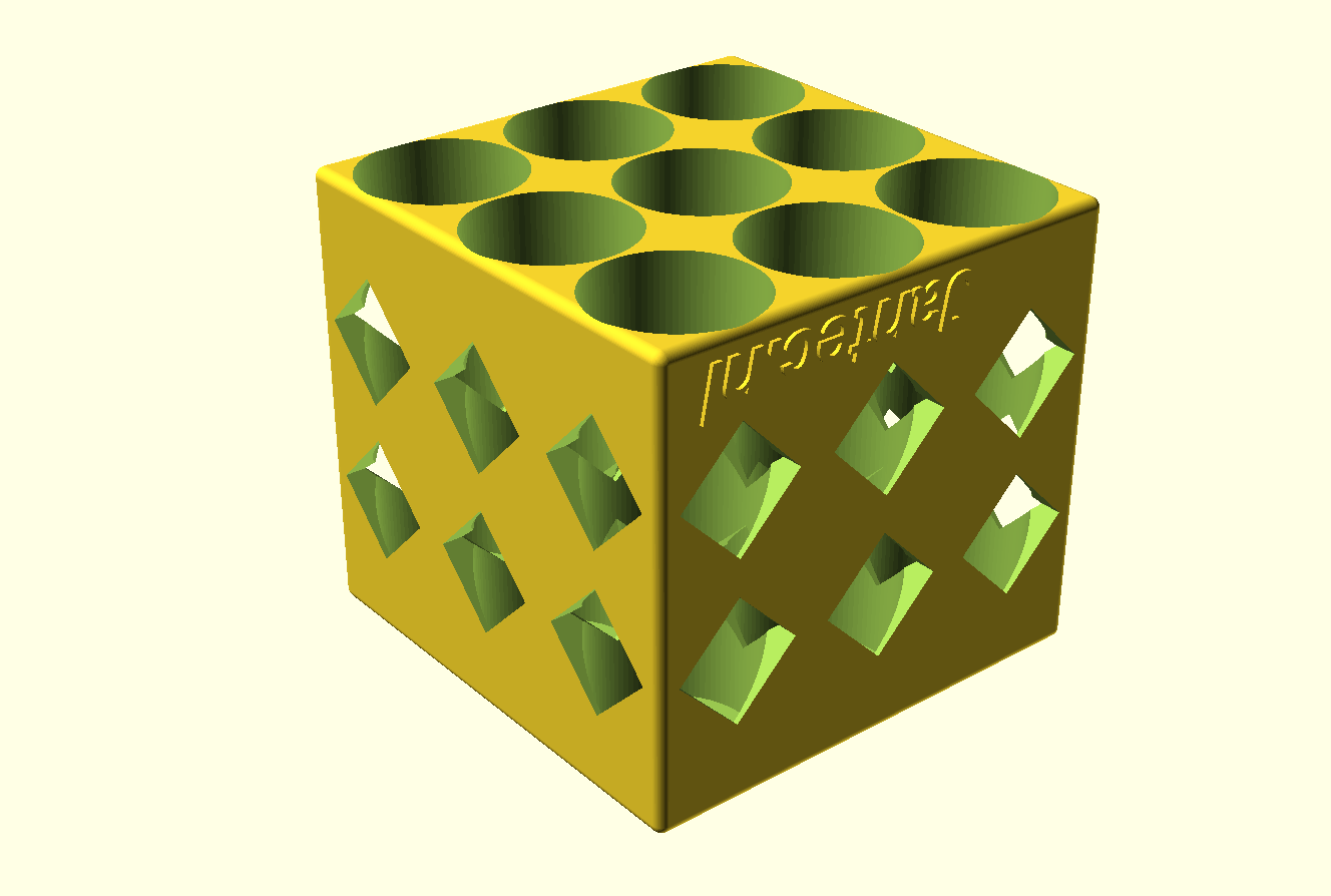
And a short version where the bottlenecks will stick out a bit:


beer bottles SHORT fridge rack with 45deg squared side holes 2023 04 20

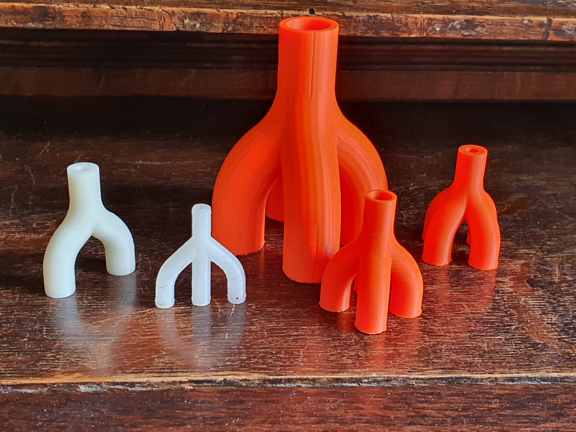
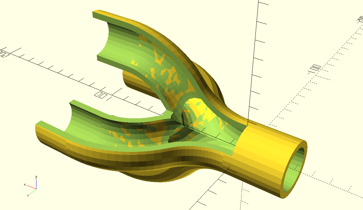
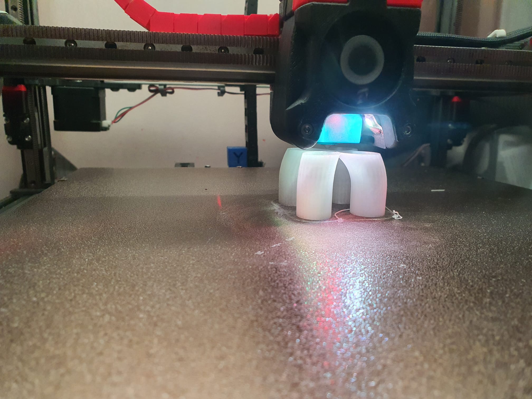
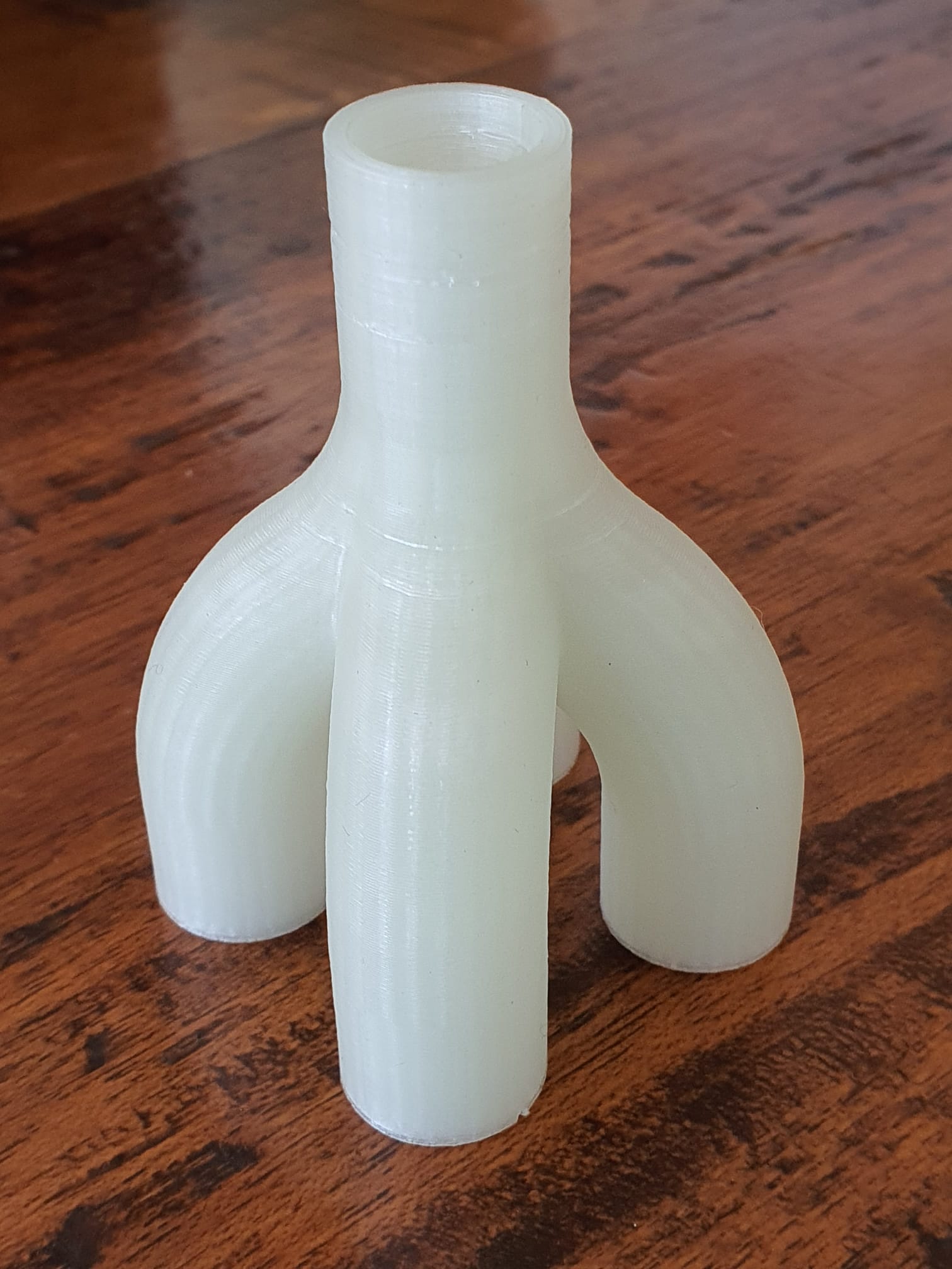
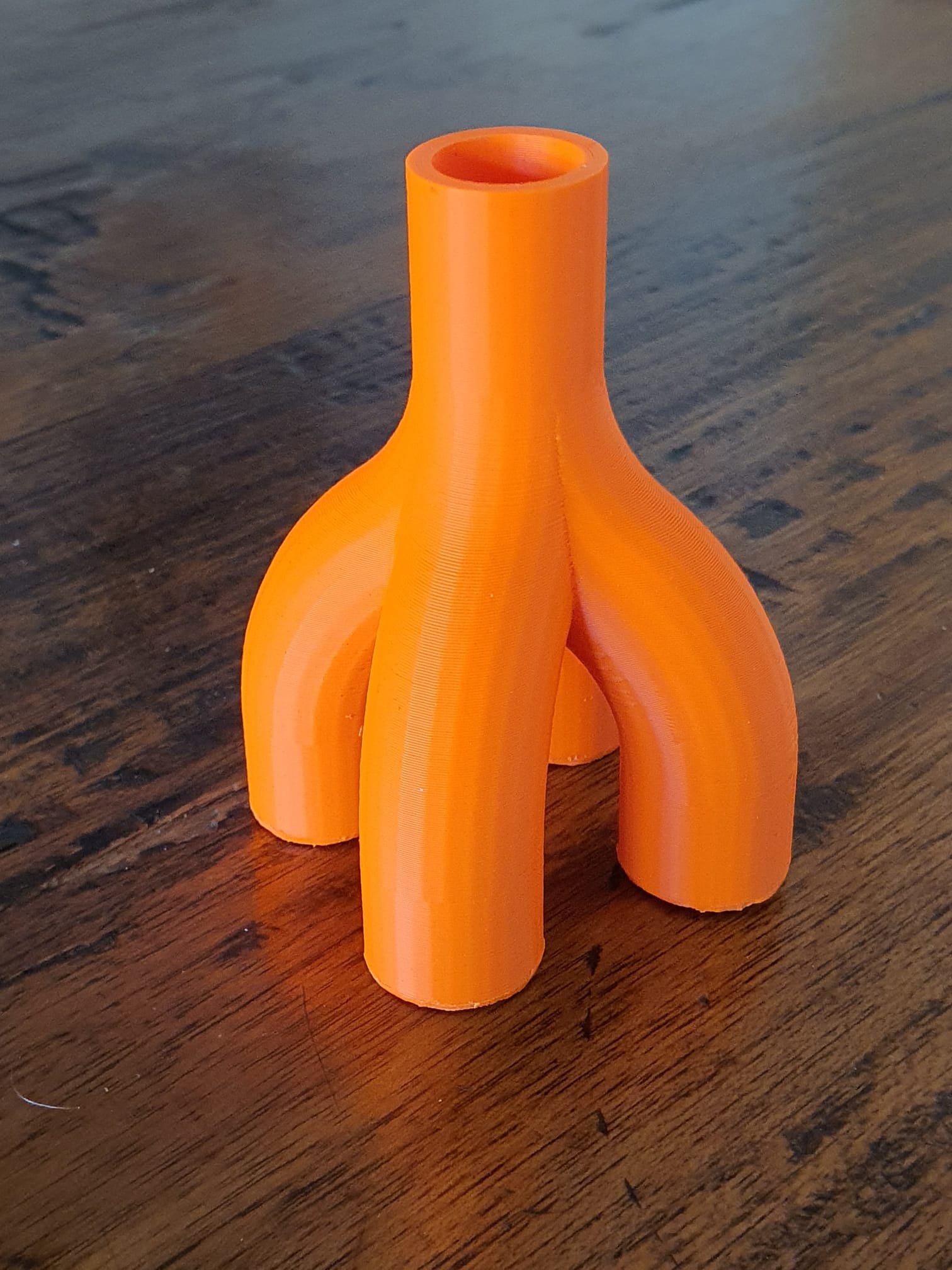
Joining multiple hollow bending tubes in Openscad with curvedPipe integrated libs

OPEN curvedPipe for pipeconnector 4 into 1 FLAT 2023 05 01 V4 dev a.SCAD

OPEN curvedPipe for pipeconnector 4 into 1 FLAT 2023 05 01 V4 dev a.STL


Inside view of the hollow pipes AND the cutouts, which required some setting changes of the Openscad program, w.r.t. higher CSG limits

Video van WhatsApp op 2023-05-02 om 23.08.14

Pipeconnector 2 into 1 all tight_hollow 2023 05 03 V4 dev b STL download


Pipeconnector 3 into 1 all hollow 2023 05 26 V5 dev d 


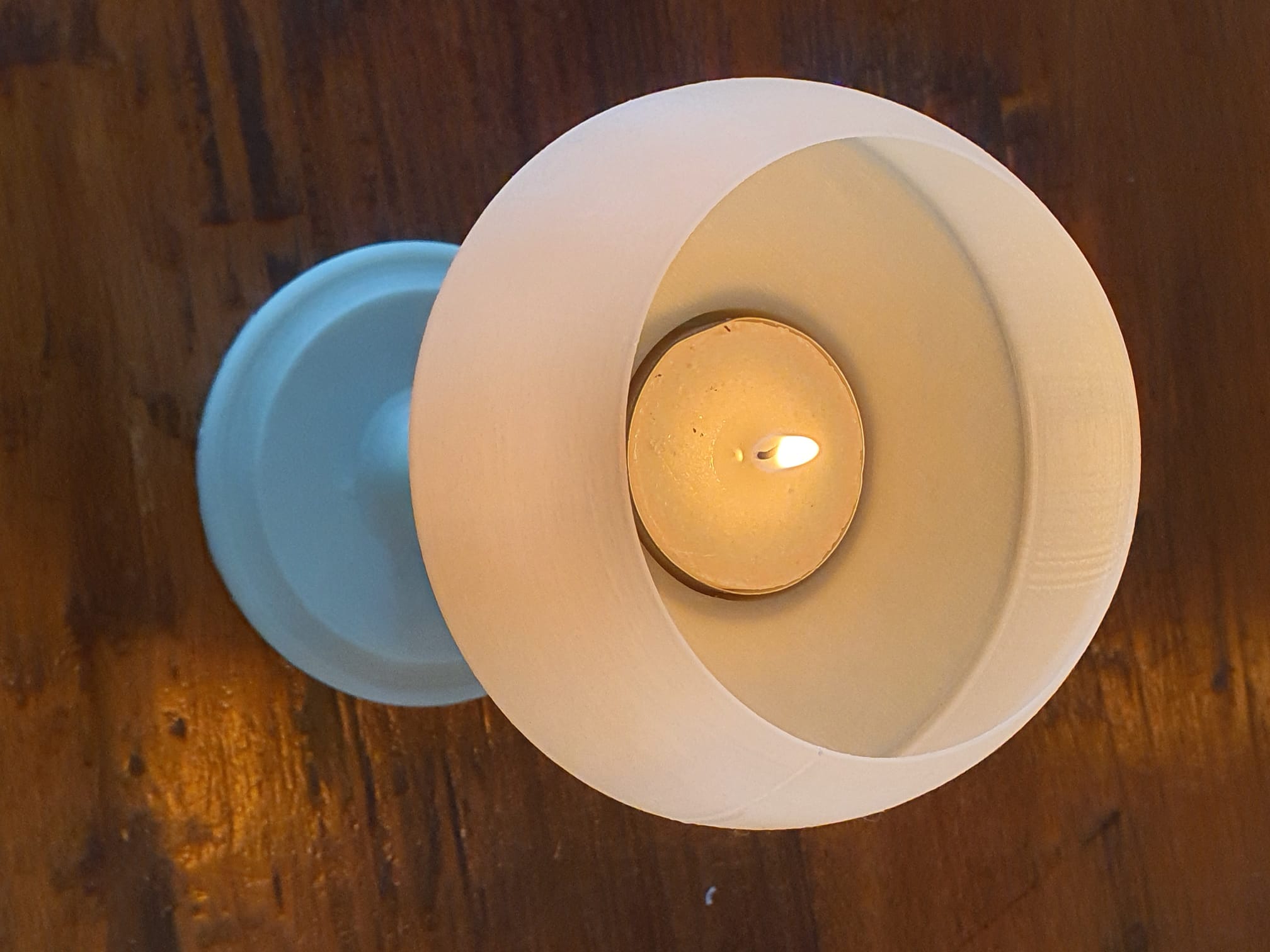
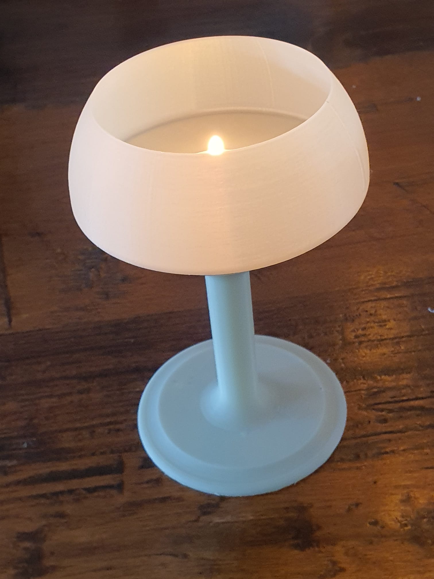
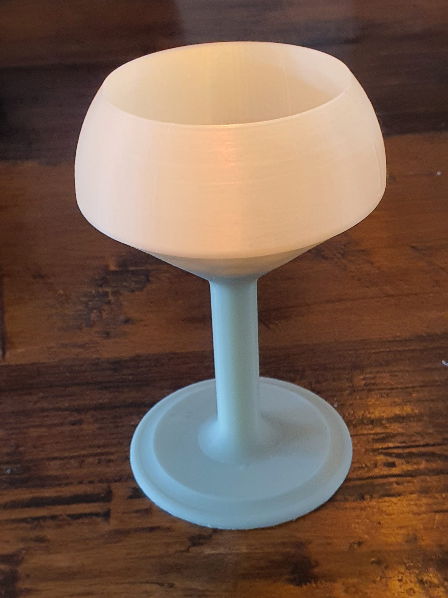
5 free printable stl files for original tabletop tealight holders

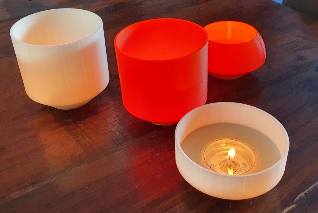
In this version, the tea light holder has a lower open spherical shape so that it can be used with a regular wax tea light.

Further down are the 4 versions of the straight flared tea light holder that are also well suited for use with a tea light.

Of course, an electric tea light is also very suitable for use with these designs.

[ NB: A design for a holder for an electric tea light with a higher inward-facing rim is in the other article. That version is not suitable for a tea light with a flame, because a flame can distort the higher, more inward edge.]

Print these STL files on a  suitable 3d-printer with heat-resistant,  fairly transparant filament for best effect!

Tea light chandelear convex and sphere Jantec.nl 2023 04 18 V9 STL DOWNLOAD


Cylinder  extra high

Tea light chandelear straight very high size Jantec.nl 2023 04 20 V2b STL DOWNLOAD


High

Tea light chandelear straight high size Jantec.nl 2023 04 20 V2b STL DOWNLOAD


Medium

Tea light chandelear straight medium size Jantec.nl 2023 04 20 V2b STL DOWNLOAD


Low

Tea light chandelear straight low size Jantec.nl 2023 04 20 V2b STL DOWNLOAD 

printable stl file for battery-operated tea light holder

Tea light chandelear simple convex and less shaved top of thinned sphere Jantec.nl 2023 04 16 V8 STL DOWNLOAD


This holder for an electric tea light with a top higher inward edge is not suitable for a tea light with a flame because a flame can distort the higher, more inward edge and may cause a fire hazard.

STL designs better suited for original tea lights with a flame are in the article: 5 free printable STL files for a table lamp with tea light


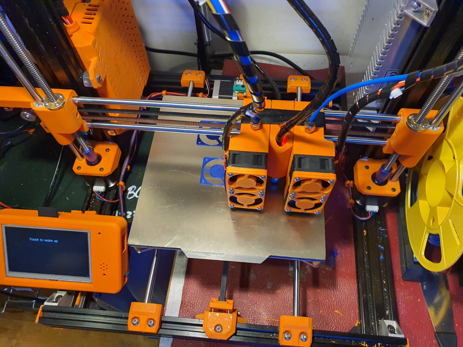
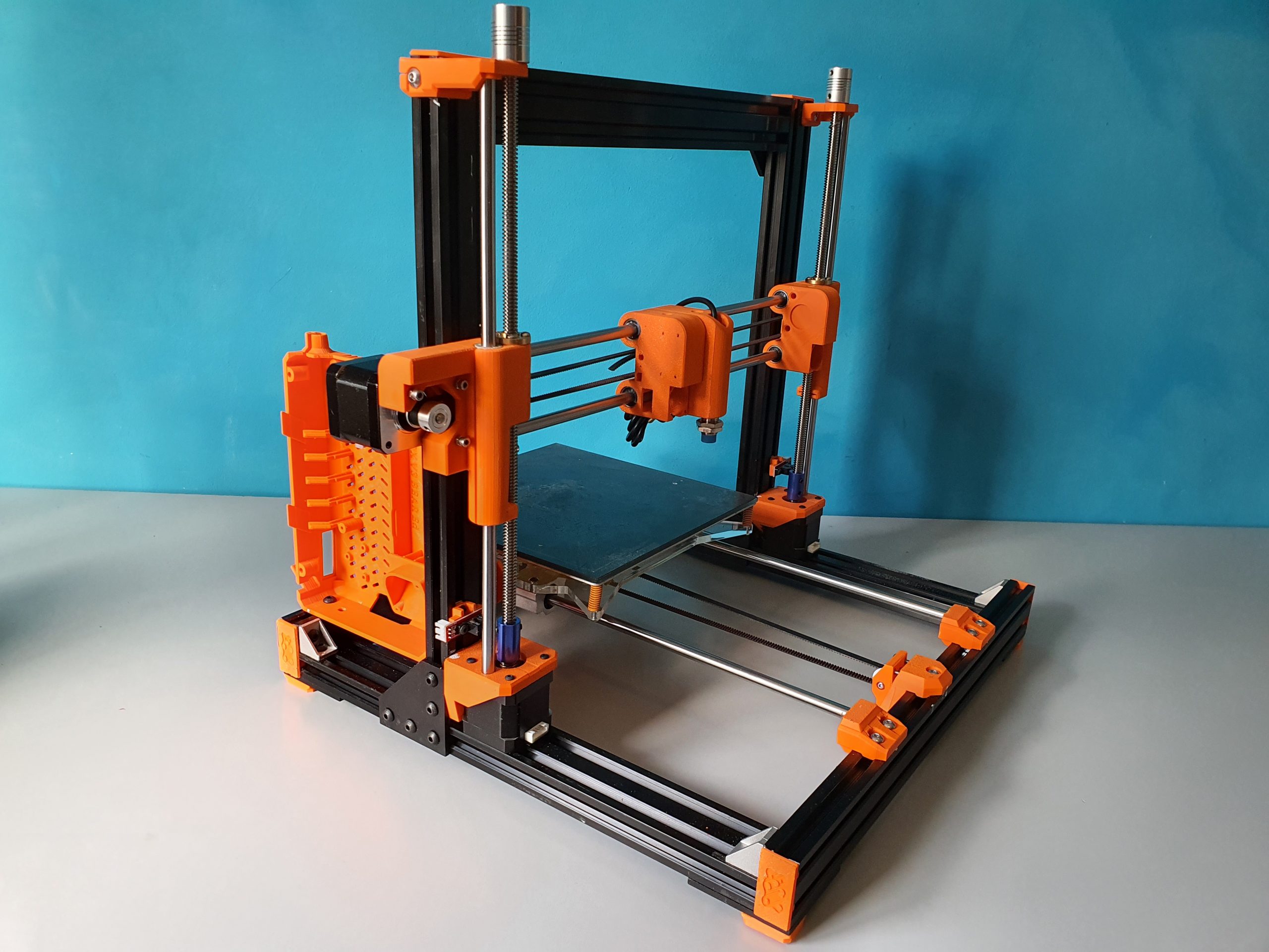
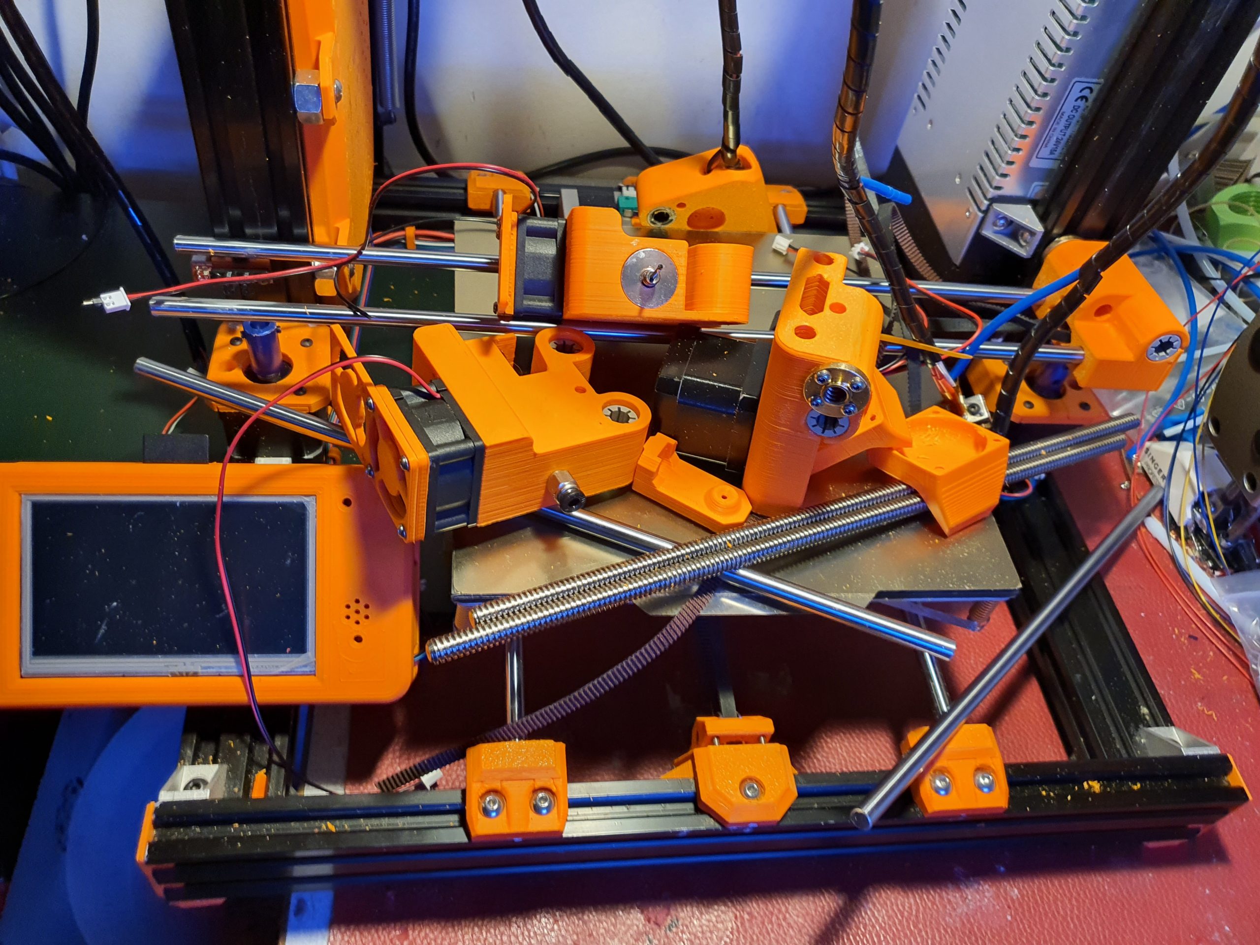
Dual magnetic parking extruders I3 Bear Duet2wifi build and Config files

My dual carriage I3-bear based 3d printer is working very well.

On this page I share my latest configuration files, my build experiences like the used STL’s , schematics and so on. 

Hope you enjoy!

Be aware that the tool settings in config.g are set including relative X, Y, Z values for this build so DO NOT put this in your slicer! 

And- you need at least RRF3.3.1 for reprap FW and for DWC. 

The sensorless homimg also requires knowledge of config settings and the good news is that the Duet2wifi has this all managed by the reprap firmware.  No switches needed or complex jumper settings!

Tip for printing the parts: I used ABS for all parts. Use at least a printer with calibrated XYZ values for your specific filament. 

Do a testcube first and apply any needed adjusting to your slicer’s settings like pre-shrinking settings of the endresult and so on. 

If you don’t do this, then don’t start this build. 

It is a prerequisite to get the magnetic carriage to deliver-and get the carriages from left and right of the X-axis. 

Therefore the movement needs to be free of unneccessary friction. 

And– if you use sensorless homing any additional friction on any sensorless homed axis might lead to unintended stalls.

I added a dripstop to the left and right hand sided X-carriages, made of some thin tinned plate.

It is positioned so, that a little tension is put on the nozzle tip in the parking position. It really works very well!

Please donate $1 to my paypal account if you use (parts of) my firmware developments so I can continue to share nice stuff for you to download

The config.g for this build and the Duet2wifi is HERE

The Sys directory for the dual carriage build and Duet2wifi is HERE

The Macros directory for the dual carriage build and Duet2wifi is HERE

The build plan for the 2040 extrusion frame is HERE

2.1 version Prusa i3 MK3/MK3S Bear Z Extended 459mm Black kit 2040  Extrusion Anodized After Cut Prusa i3 MK3 Bear Profile Frame|3D Printer  Parts & Accessories| - AliExpress

The following is available in the public domain as sharable content under the user-agreements as produced by its original authors::

The STL files for the X-axis carriages and carriages are HERE

All other needed STL files for the printer are HERE

The Duet’s case and 4.3 inch Paneldue’s case are HERE

The page of the working printer is HERE

The build plans for the electronics and Duet2wifi wiring schemes are HERE


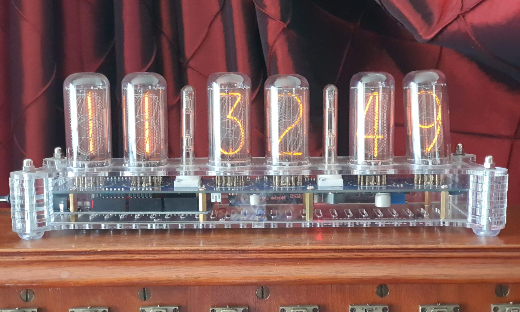
GRA-AFCH NixieClockShield_NCS318_V1_94_TZ.ino with Time zone and automated summer/winter time with example video

I added the timezone.lib plus arduino-additional code to the open-source code as GRA-AFCH made this for their  IN-18 nixie clock with Arduino Mega : NixieClockShield_NCS318_V1_94_TZ.

This is a first version that works, but it might require some coding to be done, depending on where you live.

And THIS is HOW it works:  The startup sequence is shown in the below video:

If you’re not in Western Europe, changing the timezone will be needed.

If I want to spend some more time on it, I can make it fully automated to work anywhere in the world and make the timezone setting done via the menu buttons, requires only a one time setting upon installation.  Maybe later.

This 1ST version makes the NIXIE clock sync to UTC with the help of a to be connected standard GPS module . This was already in the code. Then, the clock changes to the correct time zone, including automatic shifting for summer- and wintertime! 

In the code, I used the Western Europe timezone- and winter/summertime settings.  Also, an example is given for a US timezone. Others can be derived from the examples that come with the newly added timezone.lib from https://github.com/JChristensen/Timezone

These are the available timezones:

// Australia Eastern Time Zone (Sydney, Melbourne)
TimeChangeRule aEDT = {“AEDT”, First, Sun, Oct, 2, 660}; // UTC + 11 hours
TimeChangeRule aEST = {“AEST”, First, Sun, Apr, 3, 600}; // UTC + 10 hours
Timezone ausET(aEDT, aEST);

// Moscow Standard Time (MSK, does not observe DST)
TimeChangeRule msk = {“MSK”, Last, Sun, Mar, 1, 180};
Timezone tzMSK(msk);

// Central European Time (Frankfurt, Paris)
TimeChangeRule CEST = {“CEST”, Last, Sun, Mar, 2, 120}; // Central European Summer Time
TimeChangeRule CET = {“CET “, Last, Sun, Oct, 3, 60}; // Central European Standard Time
Timezone CE(CEST, CET);

// United Kingdom (London, Belfast)
TimeChangeRule BST = {“BST”, Last, Sun, Mar, 1, 60}; // British Summer Time
TimeChangeRule GMT = {“GMT”, Last, Sun, Oct, 2, 0}; // Standard Time
Timezone UK(BST, GMT);

// UTC
TimeChangeRule utcRule = {“UTC”, Last, Sun, Mar, 1, 0}; // UTC
Timezone UTC(utcRule);

// US Eastern Time Zone (New York, Detroit)
TimeChangeRule usEDT = {“EDT”, Second, Sun, Mar, 2, -240}; // Eastern Daylight Time = UTC – 4 hours
TimeChangeRule usEST = {“EST”, First, Sun, Nov, 2, -300}; // Eastern Standard Time = UTC – 5 hours
Timezone usET(usEDT, usEST);

// US Central Time Zone (Chicago, Houston)
TimeChangeRule usCDT = {“CDT”, Second, Sun, Mar, 2, -300};
TimeChangeRule usCST = {“CST”, First, Sun, Nov, 2, -360};
Timezone usCT(usCDT, usCST);

// US Mountain Time Zone (Denver, Salt Lake City)
TimeChangeRule usMDT = {“MDT”, Second, Sun, Mar, 2, -360};
TimeChangeRule usMST = {“MST”, First, Sun, Nov, 2, -420};
Timezone usMT(usMDT, usMST);

// Arizona is US Mountain Time Zone but does not use DST
Timezone usAZ(usMST);

// US Pacific Time Zone (Las Vegas, Los Angeles)
TimeChangeRule usPDT = {“PDT”, Second, Sun, Mar, 2, -420};
TimeChangeRule usPST = {“PST”, First, Sun, Nov, 2, -480};
Timezone usPT(usPDT, usPST);

Be aware,the way I did this is a Q&D method since i have just hacked  this into an existing piece of code, and only do a rewrite of the RTC’s original time after every sync to GPS with the new timezone and winter/summer time rules, so RTC will then become the new local time, either summer- or wintertime.

Since the time and applying the rules of timezone+ winter/summertime is continuously refreshed, not just the time is very stable, but also the changes between winter- and summertime and vice versa are automated.

The required arduino libraries are on the GRA-AFCH Github pagine:

https://github.com/afch/NixieClock

OR-just download the zipped Libraries from our website.

It works really well, please see the zipped file here or copy/paste the arduino code below (you will need some additional files than can only be retreived from the zip-file below, though).

NixieClockShield_NCS318_V1_94_TZ.ino

NixieClockShield_NCS318_V1_94_TZ.ino:

const String FirmwareVersion = “0196TZ”;
const char HardwareVersion[] PROGMEM = {“NCS318/568 FW 1.94TZ 2021_04_04 Jantec.nl add-on for Timezones for HW 1.x HV5122 or HV5222”};

//// This ‘TZ’ firmware addition delivers automated Summer/Winter time changes based on your local time zone settings ////
//// Jantec.nl 2023-04-04 The Netherlands, Amsterdam. Please share and re-use! ////
//// This can and may be used in any CLOCK program, with possibly specific minor alteration, due to different libraries and do on ////
//// All of my add-ons are specified in the code! Cheers, Jantec.nl, NL ////
//// The approach here is to automatically change the EEPROM hours setting according to the SUMMER/WINTER timecheme ////
//// meaning: Put in the register: a) the time zone (=normal winter time) versus UTC and b) at the switching times the summer ‘+1’ change versus ‘normal’wintertime ///
//// If the user changes the hours setting, this will be overruled at every programmed time change related to summer/ winter time
//Format _X.XXX_
//NIXIE CLOCK SHIELD NCS318/568 for HW 1.x by GRA & AFCH (fominalec@gmail.com)
//1.94 26.02.2021
//Added: Сhecking the presence of a gps receiver when turned on.
//Return to the previous gps parser
//1.92 21.01.2021
//Added: defines for GPS receiver types
//1.91 29.07.2020
//The driver has been changed to support BOTH HV5122 and HV5222 registers (switching using resistor R5222 Arduino pin No. 8)
//1.90 08.06.2020
//Fixed: GPS timezone issue: added breakTime(now(), tm) to adjustTime function at Time.cpp
//1.89 03.04.2020
//Dots sync with seconds
//1.88 26.03.2020
//GPS synchronization algorithm has been changed (again)
//1.86 23.02.2020
//GPS synchronization algorithm changed
//1.85.3 23.02.2020
//Added: DS3231 internal temperature sensor self test: 5 beeps if fail.
//1.85.2 21.02.2020
//Fixed: Bug with time zones more than +-9
// GPS parser has been replaced by NEOGPS
//1.85.1 05.01.2020
//Value of “HardwareVersion” was changed to NCS318/568
//1.85 14.06.2019
//indication is working inside interrupt (only for Arduino Mega), driver v1.3 is required
//Added: support programmable leds ws2812b
//Some performance optimizations
//1.84 08.04.2018
//LEDs functions moved to external file
//LEDs freezing while music (or sound) played.
//SPI Setup moved driver’s file
//1.83 02.08.2018 (Driver v 1.1 is required)
//Fixed: Temp. reading speed fixed
//Fixed: Dots mixed up (driver was updated to v. 1.1)
//Fixed: RGB LEDs reading from EEPROM
//Fixed: Check for entering data from GPS in range
//1.82 18.07.2018 Dual Date Format
//1.81 18.02.2018 Temp. sensor present analyze
//1.80 06.08.2017
//Added: Date and Time GPS synchronization
//1.70 30.07.2017
//Added IR remote control support (Sony RM-X151) (“MODE”, “UP”, “DOWN”)
//1.60 24_07_2017
//Added: Temperature reading mode in menu and slot machine transaction
//1.0.31 27_04_2017
//Added: antipoisoning effect – slot machine
//1.021 31.01.2017
//Added: time synchronizing each 10 seconds
//Fixed: not correct time reading from RTC while start up
//1.02 17.10.2016
//Fixed: RGB color controls
//Update to Arduino IDE 1.6.12 (Time.h replaced to TimeLib.h)
//1.01
//Added RGB LEDs lock(by UP and Down Buttons)
//Added Down and Up buttons pause and resume self testing
//25.09.2016 update to HW ver 1.1
//25.05.2016

//#define tubes8
#define tubes6
//#define tubes4

#include <SPI.h>
#include <Wire.h>
#include <ClickButton.h>
#include <TimeLib.h>
#ifndef GRA_AND_AFCH_TIME_LIB_MOD
#error The “Time (TimeLib)” library modified by GRA and AFCH must be used!
#endif

//// THIS IS NEW, related to TIMEZONE add-on:
#include <Timezone.h>//https://github.com/JChristensen/Timezone
//Central European Time (Frankfurt, Paris)
TimeChangeRule myDST = {“CEST”, Last, Sun, Mar, 26, 120}; //Central European Summer Time//Daylight time = UTC +2 hours
TimeChangeRule mySTD = {“CET “, Last, Sun, Oct, 3, 60}; //Central European Standard Time (Winter)//Daylight time = UTC +1 hour
Timezone myTZ(myDST, mySTD);
//ADD AND REPLACE THE ABOVE FOR ANY OTHER REQUIRED TIMEZONE FROM THE EXAMPLES IN JChistensen’s exaples folders
// US Eastern Time Zone (New York, Detroit)
//TimeChangeRule myDST = {“EDT”, Second, Sun, Mar, 2, -240}; //Daylight time = UTC – 4 hours
//TimeChangeRule mySTD = {“EST”, First, Sun, Nov, 2, -300}; //Daylight time = UTC – 4 hours
//Timezone myTZ(myDST, mySTD);
TimeChangeRule *tcr; //pointer to the time change rule, use to get the TZ abbrev
time_t utc;
//// end of this add-on for TIMEZONE

#include <Tone.h>
#include <EEPROM.h>
#include “doIndication318_HW1.x.h”
#include <OneWire.h>
//IR remote control /////////// START /////////////////////////////
#if defined(__AVR_ATmega1280__) || defined(__AVR_ATmega2560__)

#define GPS_SYNC_INTERVAL 1800000 // in milliseconds
//#define GPS_SYNC_INTERVAL 180000 //3 minutes
unsigned long Last_Time_GPS_Sync = 0;
//bool GPS_Sync_Flag = false;
//uint32_t GPS_Sync_Interval=120000; // 2 minutes
uint32_t GPS_Sync_Interval = 60000; // first try = 1 minute
uint32_t MillsNow=0;
#define TIME_TO_TRY 60000 //1 minute
bool AttMsgWasShowed=false;

#define GPS_BUFFER_LENGTH 83

char GPS_Package[GPS_BUFFER_LENGTH];
byte GPS_position = 0;

struct GPS_DATE_TIME
{
byte GPS_hours;
byte GPS_minutes;
byte GPS_seconds;
byte GPS_day;
byte GPS_mounth;
int GPS_year;
bool GPS_Valid_Data = false;
unsigned long GPS_Data_Parsed_time;
};

GPS_DATE_TIME GPS_Date_Time;

#define PreZero(digit) ((abs(digit)<10)?”0″+String(abs(digit)):String(abs(digit)))
#include <IRremote.h>
int RECV_PIN = 4;
IRrecv irrecv(RECV_PIN);
decode_results IRresults;
// buttons codes for remote controller Sony RM-X151
#define IR_BUTTON_UP_CODE 0x6621
#define IR_BUTTON_DOWN_CODE 0x2621
#define IR_BUTTON_MODE_CODE 0x7121

class IRButtonState
{
public:
int PAUSE_BETWEEN_PACKETS = 50;
int PACKETS_QTY_IN_LONG_PRESS = 18;

private:
bool Flag = 0;
byte CNT_packets = 0;
unsigned long lastPacketTime = 0;
bool START_TIMER = false;
int _buttonCode;

public: IRButtonState::IRButtonState(int buttonCode)
{
_buttonCode = buttonCode;
}

public: int IRButtonState::checkButtonState(int receivedCode)
{
if (((millis() – lastPacketTime) > PAUSE_BETWEEN_PACKETS) && (START_TIMER == true))
{
START_TIMER = false;
if (CNT_packets >= 2) {
Flag = 0;
CNT_packets = 0;
START_TIMER = false;
return 1;
}
else {
Flag = 0;
CNT_packets = 0;
return 0;
}
}
else
{
if (receivedCode == _buttonCode) { Flag = 1;}
else
{
if (!(Flag == 1)) {return 0;}
else
{
if (!(receivedCode == 0xFFFFFFFF)) {return 0;}
}
}
CNT_packets++;
lastPacketTime = millis();
START_TIMER = true;
if (CNT_packets >= PACKETS_QTY_IN_LONG_PRESS) {
Flag = 0;
CNT_packets = 0;
START_TIMER = false;
return -1;
}
else {return 0;}
}
}
};

IRButtonState IRModeButton(IR_BUTTON_MODE_CODE);
IRButtonState IRUpButton(IR_BUTTON_UP_CODE);
IRButtonState IRDownButton(IR_BUTTON_DOWN_CODE);
#endif

int ModeButtonState = 0;
int UpButtonState = 0;
int DownButtonState = 0;

//IR remote control /////////// START /////////////////////////////

/*#define GPS_BUFFER_LENGTH 83

char GPS_Package[GPS_BUFFER_LENGTH];
byte GPS_position=0;

struct GPS_DATE_TIME
{
byte GPS_hours;
byte GPS_minutes;
byte GPS_seconds;
byte GPS_day;
byte GPS_mounth;
int GPS_year;
bool GPS_Valid_Data=false;
unsigned long GPS_Data_Parsed_time;
};
*/
//GPS_DATE_TIME GPS_Date_Time;

unsigned long GPS_Data_Parsed_time;

boolean UD, LD; // DOTS control;

byte data[12];
byte addr[8];
int celsius, fahrenheit;

#define RedLedPin 9 //MCU WDM output for red LEDs 9-g
#define GreenLedPin 6 //MCU WDM output for green LEDs 6-b
#define BlueLedPin 3 //MCU WDM output for blue LEDs 3-r
#define pinSet A0
#define pinUp A2
#define pinDown A1
//#define pinBuzzer 2
const byte pinBuzzer = 2; // pomenyal
#define pinUpperDots 12 //HIGH value light a dots
#define pinLowerDots 8 //HIGH value light a dots
#define pinTemp 7
bool RTC_present;
#define US_DateFormat 1
#define EU_DateFormat 0
//bool DateFormat=EU_DateFormat;

OneWire ds(pinTemp);
bool TempPresent = false;
#define CELSIUS 0
#define FAHRENHEIT 1

String stringToDisplay = “000000”; // Content of this string will be displayed on tubes (must be 6 chars length)
int menuPosition = 0;
// 0 – time
// 1 – date
// 2 – alarm
// 3 – 12/24 hours mode
// 4 – Temperature
// 5 – TimeZone* (Only for Ardiono Mega)

byte blinkMask = B00000000; //bit mask for blinkin digits (1 – blink, 0 – constant light)
int blankMask = B00000000; //bit mask for digits (1 – off, 0 – on)

byte dotPattern = B00000000; //bit mask for separeting dots (1 – on, 0 – off)
//B10000000 – upper dots
//B01000000 – lower dots

#define DS1307_ADDRESS 0x68
byte zero = 0x00; //workaround for issue #527
int RTC_hours, RTC_minutes, RTC_seconds, RTC_day, RTC_month, RTC_year, RTC_day_of_week;

#define TimeIndex 0
#define DateIndex 1
#define AlarmIndex 2
#define hModeIndex 3
#define TemperatureIndex 4
#define TimeZoneIndex 5
#define TimeHoursIndex 6
#define TimeMintuesIndex 7
#define TimeSecondsIndex 8
#define DateFormatIndex 9
#define DateDayIndex 10
#define DateMonthIndex 11
#define DateYearIndex 12
#define AlarmHourIndex 13
#define AlarmMinuteIndex 14
#define AlarmSecondIndex 15
#define Alarm01 16
#define hModeValueIndex 17
#define DegreesFormatIndex 18
#define HoursOffsetIndex 19

#define FirstParent TimeIndex
#define LastParent TimeZoneIndex
#define SettingsCount (HoursOffsetIndex+1)
#define NoParent 0
#define NoChild 0

//——————————-0——–1——–2——-3——–4——–5——–6——–7——–8——–9———-10——-11———12———13——-14——-15———16———17——–18———-19
// names: Time, Date, Alarm, 12/24, Temperature,TimeZone,hours, mintues, seconds, DateFormat, day, month, year, hour, minute, second alarm01 hour_format Deg.FormIndex HoursOffset
// 1 1 1 1 1 1 1 1 1 1 1 1 1 1 1 1 1 1 1 1
int parent[SettingsCount] = {NoParent, NoParent, NoParent, NoParent,NoParent,NoParent,1, 1, 1, 2, 2, 2, 2, 3, 3, 3, 3, 4, 5, 6};
int firstChild[SettingsCount] = {6, 9, 13, 17, 18, 19, 0, 0, 0, NoChild, 0, 0, 0, 0, 0, 0, 0, 0, 0, 0};
int lastChild[SettingsCount] = { 8, 12, 16, 17, 18, 19, 0, 0, 0, NoChild, 0, 0, 0, 0, 0, 0, 0, 0, 0, 0};
int value[SettingsCount] = { 0, 0, 0, 0, 0, 0, 0, 0, 0, EU_DateFormat, 0, 0, 0, 0, 0, 0, 0, 24, 0, 2};
int maxValue[SettingsCount] = { 0, 0, 0, 0, 0, 0, 23, 59, 59, US_DateFormat, 31, 12, 99, 23, 59, 59, 1, 24, FAHRENHEIT, 14};
int minValue[SettingsCount] = { 0, 0, 0, 12, 0, 0, 00, 00, 00, EU_DateFormat, 1, 1, 00, 00, 00, 00, 0, 12, CELSIUS, -12};
int blinkPattern[SettingsCount] = {
B00000000, //0
B00000000, //1
B00000000, //2
B00000000, //3
B00000000, //4
B00000000, //5
B00000011, //6
B00001100, //7
B00110000, //8
B00111111, //9
B00000011, //10
B00001100, //11
B00110000, //12
B00000011, //13
B00001100, //14
B00110000, //15
B11000000, //16
B00001100, //17
B00111111, //18
B00000011, //19
};

bool editMode = false;

long downTime = 0;
long upTime = 0;
const long settingDelay = 150;
bool BlinkUp = false;
bool BlinkDown = false;
unsigned long enteringEditModeTime = 0;
bool RGBLedsOn = true;
#define RGBLEDsEEPROMAddress 0
#define HourFormatEEPROMAddress 1
#define AlarmTimeEEPROMAddress 2 //3,4,5
#define AlarmArmedEEPROMAddress 6
#define LEDsLockEEPROMAddress 7
#define LEDsRedValueEEPROMAddress 8
#define LEDsGreenValueEEPROMAddress 9
#define LEDsBlueValueEEPROMAddress 10
#define DegreesFormatEEPROMAddress 11
#define HoursOffsetEEPROMAddress 12
#define DateFormatEEPROMAddress 13

//buttons pins declarations
ClickButton setButton(pinSet, LOW, CLICKBTN_PULLUP);
ClickButton upButton(pinUp, LOW, CLICKBTN_PULLUP);
ClickButton downButton(pinDown, LOW, CLICKBTN_PULLUP);
///////////////////

Tone tone1;
#define isdigit(n) (n >= ‘0’ && n <= ‘9’)
//char *song = “MissionImp:d=16,o=6,b=95:32d,32d#,32d,32d#,32d,32d#,32d,32d#,32d,32d,32d#,32e,32f,32f#,32g,g,8p,g,8p,a#,p,c7,p,g,8p,g,8p,f,p,f#,p,g,8p,g,8p,a#,p,c7,p,g,8p,g,8p,f,p,f#,p,a#,g,2d,32p,a#,g,2c#,32p,a#,g,2c,a#5,8c,2p,32p,a#5,g5,2f#,32p,a#5,g5,2f,32p,a#5,g5,2e,d#,8d”;
char *song = “PinkPanther:d=4,o=5,b=160:8d#,8e,2p,8f#,8g,2p,8d#,8e,16p,8f#,8g,16p,8c6,8b,16p,8d#,8e,16p,8b,2a#,2p,16a,16g,16e,16d,2e”;
//char *song=”VanessaMae:d=4,o=6,b=70:32c7,32b,16c7,32g,32p,32g,32p,32d#,32p,32d#,32p,32c,32p,32c,32p,32c7,32b,16c7,32g#,32p,32g#,32p,32f,32p,16f,32c,32p,32c,32p,32c7,32b,16c7,32g,32p,32g,32p,32d#,32p,32d#,32p,32c,32p,32c,32p,32g,32f,32d#,32d,32c,32d,32d#,32c,32d#,32f,16g,8p,16d7,32c7,32d7,32a#,32d7,32a,32d7,32g,32d7,32d7,32p,32d7,32p,32d7,32p,16d7,32c7,32d7,32a#,32d7,32a,32d7,32g,32d7,32d7,32p,32d7,32p,32d7,32p,32g,32f,32d#,32d,32c,32d,32d#,32c,32d#,32f,16c”;
//char *song=”DasBoot:d=4,o=5,b=100:d#.4,8d4,8c4,8d4,8d#4,8g4,a#.4,8a4,8g4,8a4,8a#4,8d,2f.,p,f.4,8e4,8d4,8e4,8f4,8a4,c.,8b4,8a4,8b4,8c,8e,2g.,2p”;
//char *song=”Scatman:d=4,o=5,b=200:8b,16b,32p,8b,16b,32p,8b,2d6,16p,16c#.6,16p.,8d6,16p,16c#6,8b,16p,8f#,2p.,16c#6,8p,16d.6,16p.,16c#6,16b,8p,8f#,2p,32p,2d6,16p,16c#6,8p,16d.6,16p.,16c#6,16a.,16p.,8e,2p.,16c#6,8p,16d.6,16p.,16c#6,16b,8p,8b,16b,32p,8b,16b,32p,8b,2d6,16p,16c#.6,16p.,8d6,16p,16c#6,8b,16p,8f#,2p.,16c#6,8p,16d.6,16p.,16c#6,16b,8p,8f#,2p,32p,2d6,16p,16c#6,8p,16d.6,16p.,16c#6,16a.,16p.,8e,2p.,16c#6,8p,16d.6,16p.,16c#6,16a,8p,8e,2p,32p,16f#.6,16p.,16b.,16p.”;
//char *song=”Popcorn:d=4,o=5,b=160:8c6,8a#,8c6,8g,8d#,8g,c,8c6,8a#,8c6,8g,8d#,8g,c,8c6,8d6,8d#6,16c6,8d#6,16c6,8d#6,8d6,16a#,8d6,16a#,8d6,8c6,8a#,8g,8a#,c6″;
//char *song=”WeWishYou:d=4,o=5,b=200:d,g,8g,8a,8g,8f#,e,e,e,a,8a,8b,8a,8g,f#,d,d,b,8b,8c6,8b,8a,g,e,d,e,a,f#,2g,d,g,8g,8a,8g,8f#,e,e,e,a,8a,8b,8a,8g,f#,d,d,b,8b,8c6,8b,8a,g,e,d,e,a,f#,1g,d,g,g,g,2f#,f#,g,f#,e,2d,a,b,8a,8a,8g,8g,d6,d,d,e,a,f#,2g”;
#define OCTAVE_OFFSET 0
char *p;

int notes[] = { 0,
NOTE_C4, NOTE_CS4, NOTE_D4, NOTE_DS4, NOTE_E4, NOTE_F4, NOTE_FS4, NOTE_G4, NOTE_GS4, NOTE_A4, NOTE_AS4, NOTE_B4,
NOTE_C5, NOTE_CS5, NOTE_D5, NOTE_DS5, NOTE_E5, NOTE_F5, NOTE_FS5, NOTE_G5, NOTE_GS5, NOTE_A5, NOTE_AS5, NOTE_B5,
NOTE_C6, NOTE_CS6, NOTE_D6, NOTE_DS6, NOTE_E6, NOTE_F6, NOTE_FS6, NOTE_G6, NOTE_GS6, NOTE_A6, NOTE_AS6, NOTE_B6,
NOTE_C7, NOTE_CS7, NOTE_D7, NOTE_DS7, NOTE_E7, NOTE_F7, NOTE_FS7, NOTE_G7, NOTE_GS7, NOTE_A7, NOTE_AS7, NOTE_B7
};

int fireforks[] = {0, 0, 1, //1
-1, 0, 0, //2
0, 1, 0, //3
0, 0, -1, //4
1, 0, 0, //5
0, -1, 0
}; //array with RGB rules (0 – do nothing, -1 – decrese, +1 – increse

void setRTCDateTime(byte h, byte m, byte s, byte d, byte mon, byte y, byte w = 1);

int functionDownButton = 0;
int functionUpButton = 0;
bool LEDsLock = false;

//antipoisoning transaction
bool modeChangedByUser = false;
bool transactionInProgress = false; //antipoisoning transaction
#define timeModePeriod 60000
#define dateModePeriod 5000
long modesChangePeriod = timeModePeriod;
//end of antipoisoning transaction

bool GPS_sync_flag=false;

extern const int LEDsDelay;

/*******************************************************************************************************
Init Programm
*******************************************************************************************************/
void setup()
{
Wire.begin();
//setRTCDateTime(23,40,00,25,7,15,1);

Serial.begin(115200);
#if defined(__AVR_ATmega1280__) || defined(__AVR_ATmega2560__)
Serial1.begin(9600);
digitalWrite(19, HIGH);
#endif


if (EEPROM.read(HourFormatEEPROMAddress) != 12) value[hModeValueIndex] = 24; else value[hModeValueIndex] = 12;
if (EEPROM.read(RGBLEDsEEPROMAddress) != 0) RGBLedsOn = true; else RGBLedsOn = false;
if (EEPROM.read(AlarmTimeEEPROMAddress) == 255) value[AlarmHourIndex] = 0; else value[AlarmHourIndex] = EEPROM.read(AlarmTimeEEPROMAddress);
if (EEPROM.read(AlarmTimeEEPROMAddress + 1) == 255) value[AlarmMinuteIndex] = 0; else value[AlarmMinuteIndex] = EEPROM.read(AlarmTimeEEPROMAddress + 1);
if (EEPROM.read(AlarmTimeEEPROMAddress + 2) == 255) value[AlarmSecondIndex] = 0; else value[AlarmSecondIndex] = EEPROM.read(AlarmTimeEEPROMAddress + 2);
if (EEPROM.read(AlarmArmedEEPROMAddress) == 255) value[Alarm01] = 0; else value[Alarm01] = EEPROM.read(AlarmArmedEEPROMAddress);
if (EEPROM.read(LEDsLockEEPROMAddress) == 255) LEDsLock = false; else LEDsLock = EEPROM.read(LEDsLockEEPROMAddress);
if (EEPROM.read(DegreesFormatEEPROMAddress) == 255) value[DegreesFormatIndex] = CELSIUS; else value[DegreesFormatIndex] = EEPROM.read(DegreesFormatEEPROMAddress);
if (EEPROM.read(HoursOffsetEEPROMAddress) == 255) value[HoursOffsetIndex] = value[HoursOffsetIndex]; else value[HoursOffsetIndex] = EEPROM.read(HoursOffsetEEPROMAddress) + minValue[HoursOffsetIndex];

//// needed to set this HoursOffsetIndex variable to 0 since we will use the timezone lib (local timezone and summer/winter time add-ons by Jantec.nl)
value[HoursOffsetIndex] = 0;
EEPROM.write(HoursOffsetEEPROMAddress, 0);

if (EEPROM.read(DateFormatEEPROMAddress) == 255) value[DateFormatIndex] = value[DateFormatIndex]; else value[DateFormatIndex] = EEPROM.read(DateFormatEEPROMAddress);

//Serial.print(F(“led lock=”));
//Serial.println(LEDsLock);

pinMode(RedLedPin, OUTPUT);
pinMode(GreenLedPin, OUTPUT);
pinMode(BlueLedPin, OUTPUT);

tone1.begin(pinBuzzer);
song = parseSong(song);

pinMode(LEpin, OUTPUT);

// SPI setup
SPISetup();
LEDsSetup();
//buttons pins inits
pinMode(pinSet, INPUT_PULLUP);
pinMode(pinUp, INPUT_PULLUP);
pinMode(pinDown, INPUT_PULLUP);
////////////////////////////
pinMode(pinBuzzer, OUTPUT);

//buttons objects inits
setButton.debounceTime = 20; // Debounce timer in ms
setButton.multiclickTime = 30; // Time limit for multi clicks
setButton.longClickTime = 2000; // time until “held-down clicks” register

upButton.debounceTime = 20; // Debounce timer in ms
upButton.multiclickTime = 30; // Time limit for multi clicks
upButton.longClickTime = 2000; // time until “held-down clicks” register

downButton.debounceTime = 20; // Debounce timer in ms
downButton.multiclickTime = 30; // Time limit for multi clicks
downButton.longClickTime = 2000; // time until “held-down clicks” register

#if defined(__AVR_ATmega1280__) || defined(__AVR_ATmega2560__)
timerSetup();
#endif
//!!!!!!!!!!!!!!!!!!!!!!!!!!!!!!!!!!!!!!!!!!!!!!!!
doTest();
//!!!!!!!!!!!!!!!!!!!!!!!!!!!!!!!!!!!!!!!!!!!!!!!
if (LEDsLock == 1)
{
setLEDsFromEEPROM();
}
getRTCTime();
byte prevSeconds = RTC_seconds;
unsigned long RTC_ReadingStartTime = millis();
RTC_present = true;
while (prevSeconds == RTC_seconds)
{
getRTCTime();
//Serial.println(RTC_seconds);
if ((millis() – RTC_ReadingStartTime) > 3000)
{
#ifdef DEBUG
Serial.println(F(“Warning! RTC DON’T RESPOND!”));
#endif
RTC_present = false;
break;
}
}
setTime(RTC_hours, RTC_minutes, RTC_seconds, RTC_day, RTC_month, RTC_year);

#if defined(__AVR_ATmega1280__) || defined(__AVR_ATmega2560__)
irrecv.blink13(false);
irrecv.enableIRIn(); // Start the receiver
#endif

//// add-ons for TIMEZONE
time_t utc = now();
time_t local = myTZ.toLocal(utc, &tcr);
Serial.println();
printDateTime(utc, “UTC”);
printDateTime(local, tcr -> abbrev);
delay(1000);//was 10000
//// end of add-ons for TIMEZONE

}

int rotator = 0; //index in array with RGB “rules” (increse by one on each 255 cycles)
int cycle = 0; //cycles counter
int RedLight = 255;
int GreenLight = 0;
int BlueLight = 0;
unsigned long prevTime = 0; // time of lase tube was lit
unsigned long prevTime4FireWorks = 0; //time of last RGB changed
//int minuteL=0; //младшая цифра минут

/***************************************************************************************************************
MAIN Programm
***************************************************************************************************************/
void loop() {

if (((millis() % 10000) == 0) && (RTC_present)) //synchronize with RTC every 10 seconds
{
getRTCTime();

setTime(RTC_hours, RTC_minutes, RTC_seconds, RTC_day, RTC_month, RTC_year);
// 4 lines of time zone & winter/summer time additions by Jantec.nl 2023 0404
time_t utc = now();
time_t local = myTZ.toLocal(utc, &tcr);
setTime(myTZ.toLocal(utc, &tcr));
EEPROM.write(DateFormatEEPROMAddress, value[myTZ.toLocal(utc, &tcr)]);

//Serial.println(F(“Sync”));
}

#if defined(__AVR_ATmega1280__) || defined(__AVR_ATmega2560__)

MillsNow=millis();
if ((MillsNow – Last_Time_GPS_Sync) > GPS_Sync_Interval)
{
//GPS_Sync_Interval = GPS_SYNC_INTERVAL; // <—-!
//GPS_Sync_Flag = 0;
if (AttMsgWasShowed==false)
{
Serial.println(F(“Attempt to sync with GPS.”));
AttMsgWasShowed=true;
}
GetDataFromSerial1();
//SyncWithGPS();
}
if ((MillsNow – Last_Time_GPS_Sync) > GPS_Sync_Interval + TIME_TO_TRY)
{
Last_Time_GPS_Sync=MillsNow; //if it is not possible to synchronize within the allotted time TIME_TO_TRY, then we postpone attempts to the next time interval.
//GPS_Sync_Flag = 1;
//GPS_Sync_Interval = GPS_SYNC_INTERVAL;
Serial.println(F(“All attempts were unsuccessful.”));
AttMsgWasShowed=false;
}

IRresults.value = 0;
if (irrecv.decode(&IRresults)) {
Serial.println(IRresults.value, HEX);
irrecv.resume(); // Receive the next value
}

ModeButtonState = IRModeButton.checkButtonState(IRresults.value);
if (ModeButtonState == 1) Serial.println(F(“Mode short”));
if (ModeButtonState == -1) Serial.println(F(“Mode long….”));

UpButtonState = IRUpButton.checkButtonState(IRresults.value);
if (UpButtonState == 1) Serial.println(F(“Up short”));
if (UpButtonState == -1) Serial.println(F(“Up long….”));

DownButtonState = IRDownButton.checkButtonState(IRresults.value);
if (DownButtonState == 1) Serial.println(F(“Down short”));
if (DownButtonState == -1) Serial.println(F(“Down long….”));

#else
ModeButtonState=0;
UpButtonState=0;
DownButtonState=0;
#endif

p = playmusic(p);

if ((millis() – prevTime4FireWorks) > LEDsDelay)
{
rotateFireWorks(); //change color (by 1 step)
prevTime4FireWorks = millis();
}

if ((menuPosition == TimeIndex) || (modeChangedByUser == false) ) modesChanger();
#if defined (__AVR_ATmega328P__)
doIndication();
#endif

setButton.Update();
upButton.Update();
downButton.Update();
if (editMode == false)
{
blinkMask = B00000000;

} else if ((millis() – enteringEditModeTime) > 60000)
{
editMode = false;
menuPosition = firstChild[menuPosition];
blinkMask = blinkPattern[menuPosition];
}
if ((setButton.clicks > 0) || (ModeButtonState == 1)) //short click
{
modeChangedByUser = true;
p = 0; //shut off music )))
tone1.play(1000, 100);
enteringEditModeTime = millis();
/*if (value[DateFormatIndex] == US_DateFormat)
{
//if (menuPosition == )
} else */
menuPosition = menuPosition + 1;
#if defined (__AVR_ATmega328P__)
if (menuPosition == TimeZoneIndex) menuPosition++;// skip TimeZone for Arduino Uno
#endif
if (menuPosition == LastParent + 1) menuPosition = TimeIndex;
/*Serial.print(F(“menuPosition=”));
Serial.println(menuPosition);
Serial.print(F(“value=”));
Serial.println(value[menuPosition]);*/

blinkMask = blinkPattern[menuPosition];
if ((parent[menuPosition – 1] != 0) and (lastChild[parent[menuPosition – 1] – 1] == (menuPosition – 1))) //exit from edit mode
{
if ((parent[menuPosition – 1] – 1 == 1) && (!isValidDate()))
{
menuPosition = DateDayIndex;
return;
}
editMode = false;
menuPosition = parent[menuPosition – 1] – 1;
if (menuPosition == TimeIndex) setTime(value[TimeHoursIndex], value[TimeMintuesIndex], value[TimeSecondsIndex], day(), month(), year());
if (menuPosition == DateIndex)
{
#ifdef DEBUG
Serial.print(F(“Day:”));
Serial.println(value[DateDayIndex]);
Serial.print(F(“Month:”));
Serial.println(value[DateMonthIndex]);
#endif
setTime(hour(), minute(), second(), value[DateDayIndex], value[DateMonthIndex], 2000 + value[DateYearIndex]);
EEPROM.write(DateFormatEEPROMAddress, value[DateFormatIndex]);
}
if (menuPosition == AlarmIndex) {
EEPROM.write(AlarmTimeEEPROMAddress, value[AlarmHourIndex]);
EEPROM.write(AlarmTimeEEPROMAddress + 1, value[AlarmMinuteIndex]);
EEPROM.write(AlarmTimeEEPROMAddress + 2, value[AlarmSecondIndex]);
EEPROM.write(AlarmArmedEEPROMAddress, value[Alarm01]);
};
if (menuPosition == hModeIndex) EEPROM.write(HourFormatEEPROMAddress, value[hModeValueIndex]);
if (menuPosition == TemperatureIndex)
{
EEPROM.write(DegreesFormatEEPROMAddress, value[DegreesFormatIndex]);
}
if (menuPosition == TimeZoneIndex) EEPROM.write(HoursOffsetEEPROMAddress, value[HoursOffsetIndex] – minValue[HoursOffsetIndex]);
//if (menuPosition == hModeIndex) EEPROM.write(HourFormatEEPROMAddress, value[hModeValueIndex]);
setRTCDateTime(hour(), minute(), second(), day(), month(), year() % 1000, 1);
return;
} //end exit from edit mode
/*Serial.print(“menu pos=”);
Serial.println(menuPosition);
Serial.print(“DateFormat”);
Serial.println(value[DateFormatIndex]);*/
if ((menuPosition != HoursOffsetIndex) &&
(menuPosition != DateFormatIndex) &&
(menuPosition != DateDayIndex)) value[menuPosition] = extractDigits(blinkMask);
}
if ((setButton.clicks < 0) || (ModeButtonState == -1)) //long click
{
tone1.play(1000, 100);
if (!editMode)
{
enteringEditModeTime = millis();
if (menuPosition == TimeIndex) stringToDisplay = PreZero(hour()) + PreZero(minute()) + PreZero(second()); //temporary enabled 24 hour format while settings
}
if (menuPosition == DateIndex)
{
// Serial.println(“DateEdit”);
value[DateDayIndex] = day();
value[DateMonthIndex] = month();
value[DateYearIndex] = year() % 1000;
if (value[DateFormatIndex] == EU_DateFormat) stringToDisplay=PreZero(value[DateDayIndex])+PreZero(value[DateMonthIndex])+PreZero(value[DateYearIndex]);
else stringToDisplay=PreZero(value[DateMonthIndex])+PreZero(value[DateDayIndex])+PreZero(value[DateYearIndex]);
//Serial.print(“str=”);
// Serial.println(stringToDisplay);
}
menuPosition = firstChild[menuPosition];
if (menuPosition == AlarmHourIndex) {
value[Alarm01] = 1; /*digitalWrite(pinUpperDots, HIGH);*/dotPattern = B10000000;
}
editMode = !editMode;
blinkMask = blinkPattern[menuPosition];
if ((menuPosition != DegreesFormatIndex) &&
(menuPosition != HoursOffsetIndex) &&
(menuPosition != DateFormatIndex))
value[menuPosition] = extractDigits(blinkMask);
/*Serial.print(F(“menuPosition=”));
Serial.println(menuPosition);
Serial.print(F(“value=”));
Serial.println(value[menuPosition]); */
}

if (upButton.clicks != 0) functionUpButton = upButton.clicks;

if ((upButton.clicks > 0) || (UpButtonState == 1))
{
modeChangedByUser = true;
p = 0; //shut off music )))
tone1.play(1000, 100);
incrementValue();
if (!editMode)
{
LEDsLock = false;
EEPROM.write(LEDsLockEEPROMAddress, 0);
}
}

if (functionUpButton == -1 && upButton.depressed == true)
{
BlinkUp = false;
if (editMode == true)
{
if ( (millis() – upTime) > settingDelay)
{
upTime = millis();// + settingDelay;
incrementValue();
}
}
} else BlinkUp = true;

if (downButton.clicks != 0) functionDownButton = downButton.clicks;

if ((downButton.clicks > 0) || (DownButtonState == 1))
{
modeChangedByUser = true;
p = 0; //shut off music )))
tone1.play(1000, 100);
dicrementValue();
if (!editMode)
{
LEDsLock = true;
EEPROM.write(LEDsLockEEPROMAddress, 1);
EEPROM.write(LEDsRedValueEEPROMAddress, RedLight);
EEPROM.write(LEDsGreenValueEEPROMAddress, GreenLight);
EEPROM.write(LEDsBlueValueEEPROMAddress, BlueLight);
/*Serial.println(F(“Store to EEPROM:”));
Serial.print(F(“RED=”));
Serial.println(RedLight);
Serial.print(F(“GREEN=”));
Serial.println(GreenLight);
Serial.print(F(“Blue=”));
Serial.println(BlueLight);*/
}
}

if (functionDownButton == -1 && downButton.depressed == true)
{
BlinkDown = false;
if (editMode == true)
{
if ( (millis() – downTime) > settingDelay)
{
downTime = millis();// + settingDelay;
dicrementValue();
}
}
} else BlinkDown = true;

if (!editMode)
{
if ((upButton.clicks < 0) || (UpButtonState == -1))
{
tone1.play(1000, 100);
RGBLedsOn = true;
EEPROM.write(RGBLEDsEEPROMAddress, 1);
#ifdef DEBUG
Serial.println(F(“RGB=on”));
#endif
setLEDsFromEEPROM();
}
if ((downButton.clicks < 0) || (DownButtonState == -1))
{
tone1.play(1000, 100);
RGBLedsOn = false;
EEPROM.write(RGBLEDsEEPROMAddress, 0);
#ifdef DEBUG
Serial.println(F(“RGB=off”));
#endif
}
}

static bool updateDateTime = false;
float curTemp=0;
switch (menuPosition)
{
case TimeIndex: //time mode
if (!transactionInProgress) stringToDisplay = updateDisplayString();
doDotBlink();
checkAlarmTime();
blankMask = B00000000;
break;
case DateIndex: //date mode
if (!transactionInProgress) stringToDisplay = updateDateString();
dotPattern = B01000000; //turn on lower dots
checkAlarmTime();
blankMask = B00000000;
break;
case AlarmIndex: //alarm mode
//stringToDisplay=”000000″;
//unsigned long execTime;
//execTime=micros();
stringToDisplay = PreZero(value[AlarmHourIndex]) + PreZero(value[AlarmMinuteIndex]) + PreZero(value[AlarmSecondIndex]);
blankMask = B00000000;
if (value[Alarm01] == 1) dotPattern = B10000000; //turn on upper dots
else
{
dotPattern = B00000000; //turn off upper dots
}
//execTime=micros()-execTime;
//Serial.println(execTime);
checkAlarmTime();
break;
case hModeIndex: //12/24 hours mode
stringToDisplay = “00” + String(value[hModeValueIndex]) + “00”;
blankMask = B00110011;
dotPattern = B00000000; //turn off all dots
checkAlarmTime();
break;
case TemperatureIndex: //missed break
case DegreesFormatIndex:

if (!transactionInProgress)
{
curTemp=getTemperature(value[DegreesFormatIndex]);
stringToDisplay = updateTemperatureString(curTemp);
if (value[DegreesFormatIndex] == CELSIUS)
{
blankMask = B00110001;
dotPattern = B01000000;
}
else
{
blankMask = B00100011;
dotPattern = B00000000;
}
}

if (curTemp < 0) dotPattern |= B10000000;
else dotPattern &= B01111111;
break;
case TimeZoneIndex:
case HoursOffsetIndex:
stringToDisplay = String(PreZero(value[HoursOffsetIndex])) + “0000”;
blankMask = B00001111;
if (value[HoursOffsetIndex]>=0) dotPattern = B00000000; //turn off all dots
else dotPattern = B10000000; //turn on upper dots
break;
case DateFormatIndex:
if (value[DateFormatIndex] == EU_DateFormat)
{
stringToDisplay=”311299″;
blinkPattern[DateDayIndex]=B00000011;
blinkPattern[DateMonthIndex]=B00001100;
}
else
{
stringToDisplay=”123199″;
blinkPattern[DateDayIndex]=B00001100;
blinkPattern[DateMonthIndex]=B00000011;
}
break;
case DateDayIndex:
case DateMonthIndex:
case DateYearIndex:
if (value[DateFormatIndex] == EU_DateFormat) stringToDisplay=PreZero(value[DateDayIndex])+PreZero(value[DateMonthIndex])+PreZero(value[DateYearIndex]);
else stringToDisplay=PreZero(value[DateMonthIndex])+PreZero(value[DateDayIndex])+PreZero(value[DateYearIndex]);
break;
}
// IRresults.value=0;
}
#if defined (__AVR_ATmega328P__)
String PreZero(int digit)
{
digit=abs(digit);
if (digit < 10) return String(“0”) + String(digit);
//if (digit < 10) return “0” + String(digit);
else return String(digit);
}
#endif

String updateDisplayString()
{
static int prevS=-1;

if (second()!=prevS)
{
prevS=second();
return getTimeNow();
} else return stringToDisplay;
}

String getTimeNow()
{
if (value[hModeValueIndex] == 24) return PreZero(hour()) + PreZero(minute()) + PreZero(second());
else return PreZero(hourFormat12()) + PreZero(minute()) + PreZero(second());
}
//// add-on void for TIMEZONE ////////////////////////////////////////////////////////////
// format and print a time_t value, with a time zone appended.
void printDateTime(time_t t, const char *tz)
{
char buf[32];
char m[4]; // temporary storage for month string (DateStrings.cpp uses shared buffer)
strcpy(m, monthShortStr(month(t)));
sprintf(buf, “%.2d:%.2d:%.2d %s %.2d %s %d %s”,
hour(t), minute(t), second(t), dayShortStr(weekday(t)), day(t), m, year(t), tz);
Serial.println(buf);
}
/////// Jantec.nl 2023-04-04 The Netherlands, Amsterdam. Please share and re-use! ////////
void doTest()
{
Serial.print(F(“Firmware version: “));
Serial.println(FirmwareVersion.substring(1,2)+”.”+FirmwareVersion.substring(2,5));
for (byte k = 0; k < strlen_P(HardwareVersion); k++) {
Serial.print((char)pgm_read_byte_near(HardwareVersion + k));
}
Serial.println();
#ifdef DEBUG
Serial.println(F(“Start Test”));
#endif

p=song;
parseSong(p);
//p=0; //need to be deleted

LEDsTest();
#if defined(__AVR_ATmega1280__) || defined(__AVR_ATmega2560__)
if (Serial1.available() > 20) Serial.println(F(“GPS detected”));
else Serial.println(F(“GPS NOT detected!”));
#endif

#ifdef tubes8
String testStringArray[11]={“00000000″,”11111111″,”22222222″,”33333333″,”44444444″,”55555555″,”66666666″,”77777777″,”88888888″,”99999999″,””};
testStringArray[10]=FirmwareVersion+”00″;
#endif
#ifdef tubes6
String testStringArray[11]={“000000″,”111111″,”222222″,”333333″,”444444″,”555555″,”666666″,”777777″,”888888″,”999999″,””};
testStringArray[10]=FirmwareVersion;
#endif

int dlay=500;
bool test=1;
byte strIndex=-1;
unsigned long startOfTest=millis()+1000; //disable delaying in first iteration
bool digitsLock=false;
while (test)
{
if (digitalRead(pinDown)==0) digitsLock=true;
if (digitalRead(pinUp)==0) digitsLock=false;

if ((millis()-startOfTest)>dlay)
{
startOfTest=millis();
if (!digitsLock) strIndex=strIndex+1;
if (strIndex==10) dlay=2000;
if (strIndex>10) { test=false; strIndex=10;}

stringToDisplay=testStringArray[strIndex];
#ifdef DEBUG
Serial.println(stringToDisplay);
#endif
}
#if defined (__AVR_ATmega328P__)
doIndication();
#endif
}

if ( !ds.search(addr))
{
#ifdef DEBUG
Serial.println(F(“Temp. sensor not found.”));
#endif
} else TempPresent=true;

testDS3231TempSensor();

#ifdef DEBUG
Serial.println(F(“Stop Test”));
#endif
// while(1);
}

void doDotBlink()
{
if (second()%2 == 0) dotPattern = B11000000;
else dotPattern = B00000000;
}

void setRTCDateTime(byte h, byte m, byte s, byte d, byte mon, byte y, byte w)
{
Wire.beginTransmission(DS1307_ADDRESS);
Wire.write(zero); //stop Oscillator

Wire.write(decToBcd(s));
Wire.write(decToBcd(m));
Wire.write(decToBcd(h));
Wire.write(decToBcd(w));
Wire.write(decToBcd(d));
Wire.write(decToBcd(mon));
Wire.write(decToBcd(y));

Wire.write(zero); //start

Wire.endTransmission();

}

byte decToBcd(byte val) {
// Convert normal decimal numbers to binary coded decimal
return ( (val / 10 * 16) + (val % 10) );
}

byte bcdToDec(byte val) {
// Convert binary coded decimal to normal decimal numbers
return ( (val / 16 * 10) + (val % 16) );
}

void getRTCTime()
{
Wire.beginTransmission(DS1307_ADDRESS);
Wire.write(zero);
Wire.endTransmission();

Wire.requestFrom(DS1307_ADDRESS, 7);

RTC_seconds = bcdToDec(Wire.read());
RTC_minutes = bcdToDec(Wire.read());
RTC_hours = bcdToDec(Wire.read() & 0b111111); //24 hour time
RTC_day_of_week = bcdToDec(Wire.read()); //0-6 -> sunday – Saturday
RTC_day = bcdToDec(Wire.read());
RTC_month = bcdToDec(Wire.read());
RTC_year = bcdToDec(Wire.read());
}

int extractDigits(byte b)
{
String tmp = “1”;

if (b == B00000011)
{
tmp = stringToDisplay.substring(0, 2);
}
if (b == B00001100)
{
tmp = stringToDisplay.substring(2, 4);
}
if (b == B00110000)
{
tmp = stringToDisplay.substring(4);
}
return tmp.toInt();
}

void injectDigits(byte b, int value)
{
if (b == B00000011) stringToDisplay = PreZero(value) + stringToDisplay.substring(2);
if (b == B00001100) stringToDisplay = stringToDisplay.substring(0, 2) + PreZero(value) + stringToDisplay.substring(4);
if (b == B00110000) stringToDisplay = stringToDisplay.substring(0, 4) + PreZero(value);
}

bool isValidDate()
{
int days[12] = {31, 28, 31, 30, 31, 30, 31, 31, 30, 31, 30, 31};
if (value[DateYearIndex] % 4 == 0) days[1] = 29;
if (value[DateDayIndex] > days[value[DateMonthIndex] – 1]) return false;
else return true;

}

byte default_dur = 4;
byte default_oct = 6;
int bpm = 63;
int num;
long wholenote;
long duration;
byte note;
byte scale;
char* parseSong(char *p)
{
// Absolutely no error checking in here
// format: d=N,o=N,b=NNN:
// find the start (skip name, etc)

while (*p != ‘:’) p++; // ignore name
p++; // skip ‘:’

// get default duration
if (*p == ‘d’)
{
p++; p++; // skip “d=”
num = 0;
while (isdigit(*p))
{
num = (num * 10) + (*p++ – ‘0’);
}
if (num > 0) default_dur = num;
p++; // skip comma
}

// get default octave
if (*p == ‘o’)
{
p++; p++; // skip “o=”
num = *p++ – ‘0’;
if (num >= 3 && num <= 7) default_oct = num;
p++; // skip comma
}

// get BPM
if (*p == ‘b’)
{
p++; p++; // skip “b=”
num = 0;
while (isdigit(*p))
{
num = (num * 10) + (*p++ – ‘0’);
}
bpm = num;
p++; // skip colon
}

// BPM usually expresses the number of quarter notes per minute
wholenote = (60 * 1000L / bpm) * 4; // this is the time for whole note (in milliseconds)
return p;
}

// now begin note loop
static unsigned long lastTimeNotePlaying = 0;
char* playmusic(char *p)
{
if (*p == 0)
{
return p;
}
if (millis() – lastTimeNotePlaying > duration)
lastTimeNotePlaying = millis();
else return p;
// first, get note duration, if available
num = 0;
while (isdigit(*p))
{
num = (num * 10) + (*p++ – ‘0’);
}

if (num) duration = wholenote / num;
else duration = wholenote / default_dur; // we will need to check if we are a dotted note after

// now get the note
note = 0;

switch (*p)
{
case ‘c’:
note = 1;
break;
case ‘d’:
note = 3;
break;
case ‘e’:
note = 5;
break;
case ‘f’:
note = 6;
break;
case ‘g’:
note = 8;
break;
case ‘a’:
note = 10;
break;
case ‘b’:
note = 12;
break;
case ‘p’:
default:
note = 0;
}
p++;

// now, get optional ‘#’ sharp
if (*p == ‘#’)
{
note++;
p++;
}

// now, get optional ‘.’ dotted note
if (*p == ‘.’)
{
duration += duration / 2;
p++;
}

// now, get scale
if (isdigit(*p))
{
scale = *p – ‘0’;
p++;
}
else
{
scale = default_oct;
}

scale += OCTAVE_OFFSET;

if (*p == ‘,’)
p++; // skip comma for next note (or we may be at the end)

// now play the note

if (note)
{
tone1.play(notes[(scale – 4) * 12 + note], duration);
if (millis() – lastTimeNotePlaying > duration)
lastTimeNotePlaying = millis();
else return p;
tone1.stop();
}
else
{
return p;
}
#ifdef DEBUG
Serial.println(F(“Incorrect Song Format!”));
#endif
return 0; //error
}

void incrementValue()
{
enteringEditModeTime = millis();
if (editMode == true)
{
if (menuPosition != hModeValueIndex) // 12/24 hour mode menu position
value[menuPosition] = value[menuPosition] + 1; else value[menuPosition] = value[menuPosition] + 12;
if (value[menuPosition] > maxValue[menuPosition]) value[menuPosition] = minValue[menuPosition];
if (menuPosition == Alarm01)
{
if (value[menuPosition] == 1) /*digitalWrite(pinUpperDots, HIGH);*/dotPattern = B10000000; //turn on upper dots
/*else digitalWrite(pinUpperDots, LOW); */ dotPattern = B00000000; //turn off all dots
}
if (menuPosition!=DateFormatIndex) injectDigits(blinkMask, value[menuPosition]);
/*Serial.print(“value=”);
Serial.println(value[menuPosition]);*/
}
}

void dicrementValue()
{
enteringEditModeTime = millis();
if (editMode == true)
{
if (menuPosition != hModeValueIndex) value[menuPosition] = value[menuPosition] – 1; else value[menuPosition] = value[menuPosition] – 12;
if (value[menuPosition] < minValue[menuPosition]) value[menuPosition] = maxValue[menuPosition];
if (menuPosition == Alarm01)
{
if (value[menuPosition] == 1) /*digitalWrite(pinUpperDots, HIGH);*/ dotPattern = B10000000; //turn on upper dots
else /*digitalWrite(pinUpperDots, LOW);*/ dotPattern = B00000000; //turn off all dots
}
if (menuPosition!=DateFormatIndex) injectDigits(blinkMask, value[menuPosition]);
/*Serial.print(“value=”);
Serial.println(value[menuPosition]);*/
}
}

bool Alarm1SecondBlock = false;
unsigned long lastTimeAlarmTriggired = 0;
void checkAlarmTime()
{
if (value[Alarm01] == 0) return;
if ((Alarm1SecondBlock == true) && ((millis() – lastTimeAlarmTriggired) > 1000)) Alarm1SecondBlock = false;
if (Alarm1SecondBlock == true) return;
if ((hour() == value[AlarmHourIndex]) && (minute() == value[AlarmMinuteIndex]) && (second() == value[AlarmSecondIndex]))
{
lastTimeAlarmTriggired = millis();
Alarm1SecondBlock = true;
#ifdef DEBUG
Serial.println(F(“Wake up, Neo!”));
#endif
p = song;
}
}

void modesChanger()
{
if (editMode == true) return;
static unsigned long lastTimeModeChanged = millis();
static unsigned long lastTimeAntiPoisoningIterate = millis();
static int transnumber = 0;
if ((millis() – lastTimeModeChanged) > modesChangePeriod)
{
lastTimeModeChanged = millis();
if (transnumber == 0) {
menuPosition = DateIndex;
modesChangePeriod = dateModePeriod;
}
if (transnumber == 1) {
menuPosition = TemperatureIndex;
modesChangePeriod = dateModePeriod;
if (!TempPresent) transnumber = 2;
}
if (transnumber == 2) {
menuPosition = TimeIndex;
modesChangePeriod = timeModePeriod;
}
transnumber++;
if (transnumber > 2) transnumber = 0;

if (modeChangedByUser == true)
{
menuPosition = TimeIndex;
}
modeChangedByUser = false;
}
if ((millis() – lastTimeModeChanged) < 2000)
{
if ((millis() – lastTimeAntiPoisoningIterate) > 100)
{
lastTimeAntiPoisoningIterate = millis();
if (TempPresent)
{
if (menuPosition == TimeIndex) stringToDisplay = antiPoisoning2(updateTemperatureString(getTemperature(value[DegreesFormatIndex])), getTimeNow());
if (menuPosition == DateIndex) stringToDisplay = antiPoisoning2(getTimeNow(), PreZero(day()) + PreZero(month()) + PreZero(year() % 1000) );
if (menuPosition == TemperatureIndex) stringToDisplay = antiPoisoning2(PreZero(day()) + PreZero(month()) + PreZero(year() % 1000), updateTemperatureString(getTemperature(value[DegreesFormatIndex])));
} else
{
if (menuPosition == TimeIndex) stringToDisplay = antiPoisoning2(PreZero(day()) + PreZero(month()) + PreZero(year() % 1000), getTimeNow());
if (menuPosition == DateIndex) stringToDisplay = antiPoisoning2(getTimeNow(), PreZero(day()) + PreZero(month()) + PreZero(year() % 1000) );
}
// Serial.println(“StrTDInToModeChng=”+stringToDisplay);
}
} else
{
transactionInProgress = false;
}
}

String antiPoisoning2(String fromStr, String toStr)
{
//static bool transactionInProgress=false;
//byte fromDigits[6];
static byte toDigits[6];
static byte currentDigits[6];
static byte iterationCounter = 0;
if (!transactionInProgress)
{
transactionInProgress = true;
blankMask = B00000000;
for (int i = 0; i < 6; i++)
{
currentDigits[i] = fromStr.substring(i, i + 1).toInt();
toDigits[i] = toStr.substring(i, i + 1).toInt();
}
}
for (int i = 0; i < 6; i++)
{
if (iterationCounter < 10) currentDigits[i]++;
else if (currentDigits[i] != toDigits[i]) currentDigits[i]++;
if (currentDigits[i] == 10) currentDigits[i] = 0;
}
iterationCounter++;
if (iterationCounter == 20)
{
iterationCounter = 0;
transactionInProgress = false;
}
String tmpStr;
for (int i = 0; i < 6; i++)
tmpStr += currentDigits[i];
return tmpStr;
}

String updateDateString()
{
static unsigned long lastTimeDateUpdate = millis()+1001;
static String DateString = PreZero(day()) + PreZero(month()) + PreZero(year() % 1000);
static byte prevoiusDateFormatWas=value[DateFormatIndex];
if (((millis() – lastTimeDateUpdate) > 1000) || (prevoiusDateFormatWas != value[DateFormatIndex]))
{
lastTimeDateUpdate = millis();
if (value[DateFormatIndex]==EU_DateFormat) DateString = PreZero(day()) + PreZero(month()) + PreZero(year() % 1000);
else DateString = PreZero(month()) + PreZero(day()) + PreZero(year() % 1000);
}
return DateString;
}

#if defined(__AVR_ATmega1280__) || defined(__AVR_ATmega2560__)

void SyncWithGPS()
{
if ((millis() – GPS_Date_Time.GPS_Data_Parsed_time) > 3000) {
Serial.println(F(“Parsed data to old”));
return;
}
Serial.println(F(“Updating time from GPS…”));
Serial.println(GPS_Date_Time.GPS_hours);
Serial.println(GPS_Date_Time.GPS_minutes);
Serial.println(GPS_Date_Time.GPS_seconds);

setTime(GPS_Date_Time.GPS_hours, GPS_Date_Time.GPS_minutes, GPS_Date_Time.GPS_seconds, GPS_Date_Time.GPS_day, GPS_Date_Time.GPS_mounth, GPS_Date_Time.GPS_year % 1000);
adjustTime((long)value[HoursOffsetIndex] * 3600);
setRTCDateTime(hour(), minute(), second(), day(), month(), year() % 1000, 1);
Last_Time_GPS_Sync = MillsNow;
GPS_Sync_Interval = GPS_SYNC_INTERVAL;
AttMsgWasShowed=false;

//// TIMEZONE add-ons
while (!Serial) ; // wait until Arduino Serial Monitor opens
//setSyncProvider(RTC.get); // the function to get the time from the RTC
//if(timeStatus()!= timeSet)
// Serial.println(“Unable to sync with the RTC”);
//else
// Serial.println(“RTC has set the system time”);

time_t utc = now();
time_t local = myTZ.toLocal(utc, &tcr);
Serial.println();
printDateTime(utc, “UTC”);
printDateTime(local, tcr -> abbrev);

setTime(myTZ.toLocal(utc, &tcr));
EEPROM.write(DateFormatEEPROMAddress, value[myTZ.toLocal(utc, &tcr)]);
//Serial.println(EEPROM.read(HourFormatEEPROMAddress));// check whether the new timezon’s winter /summer time is put in memory
//setTime(hour(), minute(), second(), value[DateDayIndex], value[DateMonthIndex], 2000 + value[DateYearIndex]);
//EEPROM.write(DateFormatEEPROMAddress, value[DateFormatIndex]);

//// End of TIMEZONE add-ons


}

void GetDataFromSerial1()
{
if (Serial1.available()) { // If anything comes in Serial1 (pin 19)
byte GPS_incoming_byte;
GPS_incoming_byte = Serial1.read();
//Serial.write(GPS_incoming_byte);
GPS_Package[GPS_position] = GPS_incoming_byte;
GPS_position++;
if (GPS_position == GPS_BUFFER_LENGTH – 1)
{
GPS_position = 0;
// Serial.println(“more then BUFFER_LENGTH!!!!”);
}
if (GPS_incoming_byte == 0x0A)
{
GPS_Package[GPS_position] = 0;
GPS_position = 0;
if (ControlCheckSum()) {
if (GPS_Parse_DateTime()) SyncWithGPS();
}

}
}
}

bool GPS_Parse_DateTime()
{
bool GPSsignal = false;
if (!((GPS_Package[0] == ‘$’)
&& (GPS_Package[3] == ‘R’)
&& (GPS_Package[4] == ‘M’)
&& (GPS_Package[5] == ‘C’))) {
return false;
}
else
{
// Serial.println(“RMC!!!”);
}
//Serial.print(“hh: “);
int hh = (GPS_Package[7] – 48) * 10 + GPS_Package[8] – 48;
//Serial.println(hh);
int mm = (GPS_Package[9] – 48) * 10 + GPS_Package[10] – 48;
//Serial.print(“mm: “);
//Serial.println(mm);
int ss = (GPS_Package[11] – 48) * 10 + GPS_Package[12] – 48;
//Serial.print(“ss: “);
//Serial.println(ss);

byte GPSDatePos = 0;
int CommasCounter = 0;
for (int i = 12; i < GPS_BUFFER_LENGTH ; i++)
{
if (GPS_Package[i] == ‘,’)
{
CommasCounter++;
if (CommasCounter == 8)
{
GPSDatePos = i + 1;
break;
}
}
}
//Serial.print(“dd: “);
int dd = (GPS_Package[GPSDatePos] – 48) * 10 + GPS_Package[GPSDatePos + 1] – 48;
//Serial.println(dd);
int MM = (GPS_Package[GPSDatePos + 2] – 48) * 10 + GPS_Package[GPSDatePos + 3] – 48;
//Serial.print(“MM: “);
//Serial.println(MM);
int yyyy = 2000 + (GPS_Package[GPSDatePos + 4] – 48) * 10 + GPS_Package[GPSDatePos + 5] – 48;
//Serial.print(“yyyy: “);
//Serial.println(yyyy);
//if ((hh<0) || (mm<0) || (ss<0) || (dd<0) || (MM<0) || (yyyy<0)) return false;
if ( !inRange( yyyy, 2018, 2038 ) ||
!inRange( MM, 1, 12 ) ||
!inRange( dd, 1, 31 ) ||
!inRange( hh, 0, 23 ) ||
!inRange( mm, 0, 59 ) ||
!inRange( ss, 0, 59 ) ) return false;
else
{
GPS_Date_Time.GPS_hours = hh;
GPS_Date_Time.GPS_minutes = mm;
GPS_Date_Time.GPS_seconds = ss;
GPS_Date_Time.GPS_day = dd;
GPS_Date_Time.GPS_mounth = MM;
GPS_Date_Time.GPS_year = yyyy;
GPS_Date_Time.GPS_Data_Parsed_time = millis();
//Serial.println(“Precision TIME HAS BEEN ACCURED!!!!!!!!!”);
//GPS_Package[0]=0x0A;
return 1;
}
}

uint8_t ControlCheckSum()
{
uint8_t CheckSum = 0, MessageCheckSum = 0; // check sum
uint16_t i = 1; // 1 sybol left from ‘$’

while (GPS_Package[i] != ‘*’)
{
CheckSum ^= GPS_Package[i];
if (++i == GPS_BUFFER_LENGTH) {
//Serial.println(F(“End of the line not found”)); // end of line not found
return 0;
}
}

if (GPS_Package[++i] > 0x40) MessageCheckSum = (GPS_Package[i] – 0x37) << 4; // ASCII codes to DEC convertation
else MessageCheckSum = (GPS_Package[i] – 0x30) << 4;
if (GPS_Package[++i] > 0x40) MessageCheckSum += (GPS_Package[i] – 0x37);
else MessageCheckSum += (GPS_Package[i] – 0x30);

if (MessageCheckSum != CheckSum) {
//Serial.println(F(“wrong checksum”)); // wrong checksum
return 0;
}
//Serial.println(“Checksum is ok”);
return 1; // all ok!
}

boolean inRange( int no, int low, int high )
{
if ( no < low || no > high )
{
Serial.println(F(“Date or Time not in range”));
//Serial.println(String(no) + “:” + String (low) + “-” + String(high));
return false;
}
return true;
}

#endif

String updateTemperatureString(float fDegrees)
{
static unsigned long lastTimeTemperatureString=millis()+1100;
static String strTemp =”000000″;
if ((millis() – lastTimeTemperatureString) > 1000)
{
//Serial.println(F(“Updating temp. str.”));
lastTimeTemperatureString = millis();
int iDegrees = round(fDegrees);
if (value[DegreesFormatIndex] == CELSIUS)
{
strTemp = “0” + String(abs(iDegrees)) + “0”;
if (abs(iDegrees) < 1000) strTemp = “00” + String(abs(iDegrees)) + “0”;
if (abs(iDegrees) < 100) strTemp = “000” + String(abs(iDegrees)) + “0”;
if (abs(iDegrees) < 10) strTemp = “0000” + String(abs(iDegrees)) + “0”;
}else
{
strTemp = “0” + String(abs(iDegrees)) + “0”;
if (abs(iDegrees) < 1000) strTemp = “00” + String(abs(iDegrees)/10) + “00”;
if (abs(iDegrees) < 100) strTemp = “000” + String(abs(iDegrees)/10) + “00”;
if (abs(iDegrees) < 10) strTemp = “0000” + String(abs(iDegrees)/10) + “00”;
}

#ifdef tubes8
strTemp= “”+strTemp+”00”;
#endif
return strTemp;
}
return strTemp;
}

float getTemperature (boolean bTempFormat)
{
static float fDegrees;
static int iterator=0;
static byte TempRawData[2];
/*unsigned long execTime=0;
execTime=micros();*/
switch (iterator)
{
case 0: ds.reset(); break;
case 1: ds.write(0xCC, 0); break; //skip ROM command
case 2: ds.write(0x44, 0); break; //send make convert to all devices
case 3: ds.reset(); break;
case 4: ds.write(0xCC, 0); break; //skip ROM command
case 5: ds.write(0xBE, 0); break; //send request to all devices
case 6: TempRawData[0] = ds.read(); break;
case 7: TempRawData[1] = ds.read(); break;
default: break;
}

if (iterator == 7)
{
int16_t raw = (TempRawData[1] << 8) | TempRawData[0];
if (raw == -1) raw = 0;
float celsius = (float)raw / 16.0;
//celsius = celsius + (float)value[TempAdjustIndex]/10;//users adjustment

if (!bTempFormat) fDegrees = celsius * 10;
else fDegrees = (celsius * 1.8 + 32.0) * 10;
}
/*execTime=micros()-execTime;
Serial.print(iterator);
Serial.println(execTime);*/
iterator++;
if (iterator==8) iterator=0;
return fDegrees;
}

#if defined(__AVR_ATmega1280__) || defined(__AVR_ATmega2560__)
ISR(TIMER4_COMPA_vect)
{
sei();
doIndication();
}

void timerSetup()
{
//timer3 setup for calling doIndication function
TCCR4A = 0; //control registers reset (WGM21, WGM20)
TCCR4B = 0; //control registers reset
TCCR4B = (1 << CS12)|(1 << CS10)|(1 << WGM12); //prescaler 1024 and CTC mode
//OCR5A = 31; //2 mS
TCNT4=0; //reset counter to 0
OCR4A = 46; //3mS
//OCR4A = 92; //6mS
TIMSK4 = (1 << OCIE1A);//TIMER3_COMPA_vect interrupt enable
sei();
}
#endif

void testDS3231TempSensor()
{
int8_t DS3231InternalTemperature=0;
Wire.beginTransmission(DS1307_ADDRESS);
Wire.write(0x11);
Wire.endTransmission();

Wire.requestFrom(DS1307_ADDRESS, 2);
DS3231InternalTemperature=Wire.read();
Serial.print(F(“DS3231_T=”));
Serial.println(DS3231InternalTemperature);
if ((DS3231InternalTemperature<5) || (DS3231InternalTemperature>60))
{
Serial.println(F(“Faulty DS3231!”));
for (int i=0; i<5; i++)
{
tone1.play(1000, 1000);
delay(2000);
}
}
}
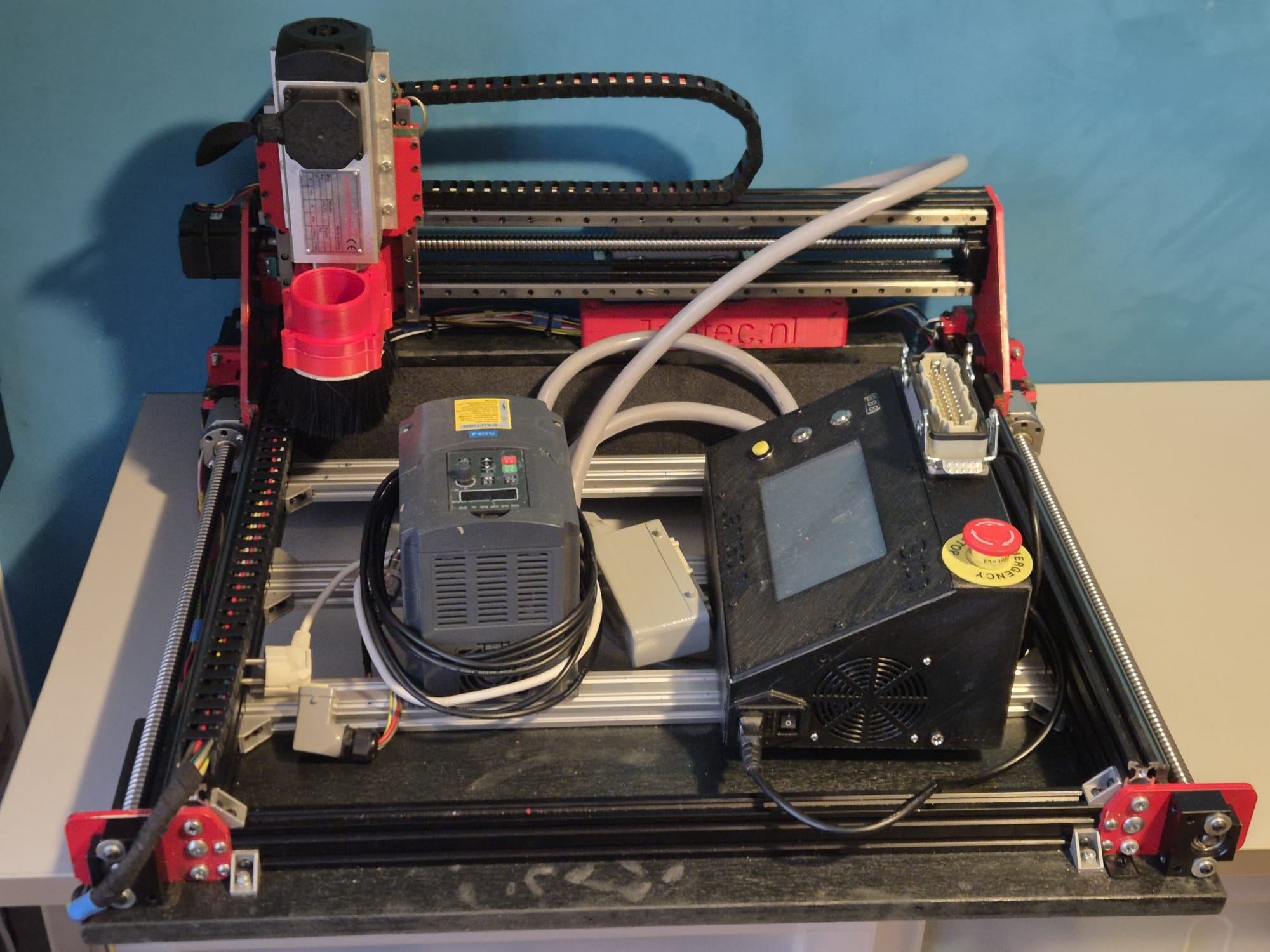
Xmas star door/ window hanger Arduino nano and WS2812 LEDS with LDR

The latest arduino code WITH LDR is HERE:

The LDR is to be soldered between A0 and GND.

The data output is D5 and this must be connected to Data-in of the WS2812 (B) string.  5V and GND goes to the power source, which is also connected to the Arduino Nano.

The STL file for the star parts is HERE.  Print this x5 in semi-transparant white.

The small Xmas- star measures 50cm in diameter from left- tip to right-tip. I printed it with glow in the dark ABS, white.  It glows in very faint green, it is just enough to glow a little and keeps your eyes focused on the star when it is not lit.

If you make the star legs watertight with silicon sealant, the star can easily be attached to an outside wall, door or fence.

ou can use a long 3-wire cable between the Nano and the Xmas star to keep the electronics mounted inside the house and the star outside, or as I did: hang the star inside, in front of any window.  I have the star hanging in my front door window, which gives amazing effect due to the non-transparant glass.

The programming can be altered to make the light effects behaviour any way you like.  I usually have a non-stroboscopic fluent scene running.

You need to print 5 star points, feed the LEDs through them and then have the wires come out somewhere.  You can glue the points together with hotglue or transparent silicone sealant after assembly and testing.

If you don’t have the Arduino IDE yet, download the app from the Microsoft website (Arduino IDE) nor from the Arduino cummunity forum.

Make sure you download my Arduino code and open it with the Arduino IDE APP. Probably the APP will have to move the arduino INO file to a new directory but that should do the trick. If not, start the Arduino app, open my code in notepad and copy/paste it as fully new code into Arduino:  Replace the example code that automatically opens when you open the Arduino program/app with my code.  Save it and rum it to see wether you need to add any library.  For adding libraries, find general help in the Arduino forum.  In my code, you can find the names of the required libraries.

undefined

In the Arduino IDE select the right microprocessor (Arduino Nano).  Then select the correct processor version (large or small memory) and the old or new bootloader.  These choices depend on the type of Nano you bought or still had lying around.  Then you choose the right port (USB) for your Nano.

To test if you have connection between IDE and Nano , you can ask if the Arduino IDE can read your Nano.  Only then you can start loading the Nano with the complicated program.

The BIG 70cm width 5-pointed star with thin hollow legs to put the WS2812 LED string through. AND an integrated tube to put the wiring through


The Arduino programming file is HERE.

The latest arduino code WITH LDR is HERE:

The STL file for the big star is HERE.

Afterthougts: I also made circular designs, dual oval crossing designs and a lot of designs that I tied to existing shapes like a steel star, some Xmas animals and so on.  The light design I made varies per application,  A star typically requires a specific design due to its shape.  A cicular design needs more of a scattered design and a straight string or a balcony-wrapped design all require specific patterns of LED programs.

I will also try to implement an auto-scanner in the setup part of the code to identify the number of LEDS that is used, since this is required to get good petterns to the string used.  (set NUMPIXELS automatically)

Mamiya RZ67 downloads

RZ67_Pro_v4 original user manual

Mamiya-RZ67-pro- repair_manual


A complete Mamiya RZ67 Pierre-Gilles guide to the Mamiya RZ67 Pro part one deep system overview

A complete guide to the Mamiya RZ67 part two film holder system

A complete guide to the Mamiya RZ67 part 3 lenses filters and accessories

A complete guide to the Mamiya RZ67 part 4 maintenance and miscellaneous accessories

A complete guide to the Mamiya RZ67 part 5 conclusion and Pierre Gilles’s personal stories

Mamiya_RZ67_AE_Prism_Finder_II_Product_Sheet

Mamiya_RZ67_AE_Prism_Finder_Product_Sheet

Mamiya RZ67 PD Prism Finder

Mamiya RB-RZ67 Polaroid Back

Mamiya RZ67 Winder II RZ

Mamiya RZ67 Winder RZ

Mamiya RZ67 Pro II Electrical Contact Cover

Mamiya RZ67 Teleconverter 1.4x

Mamiya_RZ67_140mm_Macro_MLA_Product_Sheet

Mamiya RZ67 100-200mm Zoom

Mamiya RZ67 37mm f4.5 Fisheye

Mamiya_RZ67PRO IID_Instructions

Mamiya RZ67 Pro II Instructions

MamiyaRZ67_Pro_v4

Mamiya-RZ67-parts-catalogue

Mamiya-Seiko-Shutter-Repair

mamiya_rz67_250_apo_lens_repair_diagram

mamiya_rz_140mm_m_l_a_diagram

mamiya_rz67_37mm_fisheye_lens_repair_diagram

Mamiya-RZ67-repair-manual-part1

Mamiya-RZ67-repair-manual-part2

Mamiya_RZ67_Z_Interchangeable_Lenses_Product_Sheet


Pierre Gilles’s emulsive pages


leaf-aptus-user-guide

LeafAptus65 specsheet

Description Leaf_Raw_Converter_1_2_6 PDF only

Leaf_Raw_Converter_1_2_6_installer_PC ZIP_file


STL files RZ67 CAPS, and a lot more for 3D printing


mamiya-rB67-pro-service_instructions, for reference only

Circular clock WS2812 & Arduino nano

LEES DIT ARTIKEL IN HET NEDERLANDS

In the above video you see all required parts for the elctronics.  An arduino Nano, a time module LS3231 with battery back-up and a 4-parts ring each with 15 WS2812 LED’s that provide a 160mm 60 LED units clock.  You can build it as an open built unit as shown above with wire strings or in a 3d printable slim case that I developed.  See the pictures below.

For building this nice precise clock, you can use my design files for the housing on any 3d printer that has a horizontal bed size of at least 165x165mm.

Grab both the print STL’s . HERE. from the Prusa shared site where I uploaded these designs. (If the link breaks, search on the prusa site for ws2812 circular arduino clock).

OR get the STL file for the clock’s FRONT from my website HERE

AND get the STL file for the clock’s REAR from my website HERE

One STL is for the rear and includes the Nano box, the other is for the front face of the clock.  Position the rear STL 180 degrees (so up goes down) in your slicer, so both the box and the LED housing are at Z-0 level, i.e. facing down at the same horizontal level.   The front can best be printed with the flat side down.  ABS is not recommended since it has less stiffness, but will probably also work.  For me PETG or PLA works best.

Use white filament for the front part, the rear can be any color you like.

In the circle the 4 WS2812 LED segments are positioned in 1 full circle of about 160mm.

Once you have the rear electronics connected, the front will slide snug over it. No glue required.  But the LED ring can best be glued in 4 places with a drop of hotglue to the base of the rear housing.  Best to do this after you are sure everything works OK.

The LED parts are available on a.o. banggood , aliexpress and so on, search for 60LED circle WS2812 that has the 160 mm outer diameter.

Each LED represents a dot either for seconds, minutes or as hour indicator.

The colors detemine the function.  Blue is also used as Quarter indicator with less intensity, to have a feeling of positioning for the other LEDS when it is dark.

Please look at the video above of the ‘open’ demo model to understand how it works.

Below you can find the Arduino code for the used Nano3, as-is.  it works for me, and in the code you will also find all required electrical connections and the used Time module’s spec.

When connected to your PC, you can program the Arduino and via the serial interface you can afterwards change special settings of the clock like brightness, special quarter dimlit indicators, et cetera.  it’s all in the code below.

The controls can be sent via a serial interface with the usb input of the Arduino, via a terminalprogram like YAT or with the Arduino IDE program’s interface.

The commands are:

  • f; fader OFF
  • F; fader ON
  • m (number); dim the 4 blue marker LED’s with value (number)
  • S; sync to RTC time
  • s; sync to System time (computer)
  • t (time); change system time to:
  • b; brightness of all non-marker LEDs

Please donate $1 to my paypal account if you use (parts of) my developed materials so I can continue to share nice stuff for you to download

Hope you will have a good build!

Cheers,

jan

The Arduino code, to be used for programming the Arduino Nano3 is available at the bottom of this post as plain text to be imported in an empty arduino file (with copy and paste).

Take care to use only the libraries and time module that are specified in the code!  The used time module is of the better generation that holds the time very well, also on standby.

When connecting the wires between the neopixel segments, the arduino and the time module, use a temperature-regulated soldering tool.  Use a fan when you are soldering and don’t inhale the toxic gases while soldering.

The Arduino code is shown below, to be imported in Arduino in an .ino file.  With Arduino, you must compile the code to get the Arduino flashed with the program.  If you want to do this easier, you can make use of the binary file I already compiled for both Arduino nano versions (with full memory and with half memory). Both Arduino nano types will be OK to use for this build, but they each require specific firmware.

The last part of this post is the Arduino program for the clock:


/**
* NeoClock
*
* Clock using 60 WS2812B/Neopixel LEDs and DS3231 RTC
* Small changes and updates made by jan Griffioen, Amsterdam Europe 2018-2021
* Libraries needed:
* * Adafruit NeoPixel (Library Manager) – Phil Burgess / Paint Your Dragon for Adafruit Industries – LGPL3
* *
* * Arduino Timezone Library (https://github.com/JChristensen/Timezone) – Jack Christensen – CC-BY-SA
* * Time Library (https://github.com/PaulStoffregen/Time) – Paul Stoffregen, Michael Margolis – LGPL2.1
*/

#include <Adafruit_NeoPixel.h>
#ifdef __AVR__
#include <avr/power.h>
#endif

#if defined(ESP8266)
#include <pgmspace.h>
#else
#include <avr/pgmspace.h>
#endif

/* for software wire use below
#include <SoftwareWire.h> // must be included here so that Arduino library object file references work
#include <RtcDS3231.h>

SoftwareWire myWire(SDA, SCL);
RtcDS3231<SoftwareWire> Rtc(myWire);
for software wire use above */

/* for normal hardware wire use below */
#include <Wire.h> // must be included here so that Arduino library object file references work
#include <RtcDS3231.h>
RtcDS3231<TwoWire> Rtc(Wire);
/* for normal hardware wire use above */

#include <TimeLib.h> //http://www.arduino.cc/playground/Code/Time
#include <Timezone.h> //https://github.com/JChristensen/Timezone

#include <EEPROM.h>

//Central European Time (Frankfurt, Paris)
TimeChangeRule CEST = {“CEST”, Last, Sun, Mar, 2, 120}; //Central European Summer Time
TimeChangeRule CET = {“CET “, Last, Sun, Oct, 3, 60}; //Central European Standard Time
Timezone CE(CEST, CET);

TimeChangeRule *tcr; //pointer to the time change rule, use to get the TZ abbrev
time_t utc;

#define PIN 5

unsigned long lastMillis = millis();
byte dimmer = 0x88;
byte hmark = 0;

byte ohour=0;
byte ominute=0;
byte osecond=0;

boolean fader=true;

Adafruit_NeoPixel strip = Adafruit_NeoPixel(60, PIN, NEO_GRB + NEO_KHZ800);

void setup() {

Serial.begin(57600);

strip.begin();
strip.setBrightness(50);

// Some example procedures showing how to display to the pixels:
// colorWipe(strip.Color(255, 0, 0), 50); // Red
//colorWipe(strip.Color(0, 255, 0), 50); // Green
//colorWipe(strip.Color(0, 0, 255), 50); // Blue
//colorWipe(strip.Color(0, 0, 0, 255), 50); // White RGBW
// Send a theater pixel chase in…
//theaterChase(strip.Color(127, 127, 127), 50); // White
theaterChase(strip.Color(127, 0, 0), 50); // Red
//theaterChase(strip.Color(0, 0, 127), 50); // Blue

//rainbow(20);
rainbowCycle(2);
//theaterChaseRainbow(50);

strip.clear();
strip.show(); // Initialize all pixels to ‘off’

Rtc.Begin();

Rtc.Enable32kHzPin(false);
Rtc.SetSquareWavePin(DS3231SquareWavePin_ModeNone);

if (!Rtc.GetIsRunning())
{
Serial.println(“Rtc was not actively running, starting now”);
Rtc.SetIsRunning(true);
}

if (!Rtc.IsDateTimeValid())
{
// Common Cuases:
// 1) the battery on the device is low or even missing and the power line was disconnected
Serial.println(“Rtc lost confidence in the DateTime!”);
}

byte eechk = EEPROM.read(0);
if(eechk == 0xAA) { //Assume this is our config and not a fresh chip
dimmer = EEPROM.read(1);
hmark = EEPROM.read(2);
fader = EEPROM.read(3);
}

timeSync();
}

void calcTime(void) {
utc = now();
CE.toLocal(utc, &tcr);
ohour = hour(utc);
ominute = minute(utc);
if(osecond != second(utc)) {
osecond = second(utc);
lastMillis = millis();

if(ominute == 0 && osecond == 0) {
//Every hour
timeSync();
}
}
}

void addPixelColor(byte pixel, byte color, byte brightness) {
color *= 8;
uint32_t acolor = brightness;
acolor <<= color;
uint32_t ocolor = strip.getPixelColor(pixel);
ocolor |= acolor;
strip.setPixelColor(pixel, ocolor);
}

void drawClock(byte h, byte m, byte s) {
strip.clear();

addPixelColor(m, 1, dimmer);

if(hmark > 0) {
for(byte i = 0; i<12; i++) {
addPixelColor((5*i), 2, hmark);
}
}

h %= 12;
h *= 5;
h += (m/12);
addPixelColor(h, 2, dimmer);
// 0x RR GG BB

if(fader) {
byte dim_s1 = dimmer;
byte dim_s2 = 0;
byte px_s2 = s+1;
if(px_s2 >= 60) px_s2 = 0;
unsigned long curMillis = millis()-lastMillis;
if(curMillis < 250) {
dim_s2 = 0;
dim_s1 = dimmer;
}else{
dim_s2 = map(curMillis, 250, 1000, 0, dimmer);
dim_s1 = dimmer – map(curMillis, 250, 1000, 0, dimmer);
}

// Add blue low intensity dots for 12(0),3, 6 and 9 O’çlock to verify where the clock is positioned..
addPixelColor(15, 128, 10);
addPixelColor(30, 128, 10);
addPixelColor(45, 128, 10);
addPixelColor(0, 128, 40);

addPixelColor(s, 0, dim_s1);
addPixelColor(px_s2, 0, dim_s2);
}else{
addPixelColor(s, 0, dimmer);
}

// add a background color
// setBrightness(Serial.parseInt());
// uint16_t j;
// for(j=0; j<60; j++) { // 1 cycles of colors on wheel
// strip.setPixelColor(j, Wheel(((j * 256 / strip.numPixels()) + j) & 255));
// }

strip.show();
}

byte rounds = 0;

void loop() {
calcTime();

if(rounds++ > 100) {
Serial.print(ohour);
Serial.print(“:”);
Serial.print(ominute);
Serial.print(“:”);
Serial.print(osecond);
Serial.println(“(C)JG-2020”);
rounds = 0;

}
//rainbow(21);
if (osecond == 59){theaterChase(strip.Color(0, 0, 127), 40); }// Blue; }
//if (ominute == 59 AND osecond == 59){theaterChase(strip.Color(0, 127, 0), 50); }// Green}
//if (ohour == 11 AND ominute == 59 AND osecond == 59){theaterChase(strip.Color(127, 127, 0), 50); }// Green}
else {drawClock(ohour,ominute,osecond);}

delay(10);

chkSer();
}

void timeSync(void) {
RtcDateTime dt = Rtc.GetDateTime();
setTime(dt.Hour(),dt.Minute(),dt.Second(),dt.Day(),dt.Month(),dt.Year());

Serial.print(“Synced to: “);
Serial.print(dt.Year());
Serial.print(“-“);
Serial.print(dt.Month());
Serial.print(“-“);
Serial.print(dt.Day());
Serial.print(“-“);
Serial.print(dt.Hour());
Serial.print(“-“);
Serial.print(dt.Minute());
Serial.print(“-“);
Serial.println(dt.Second());
}

void timeSave(void) {
utc = now();

RtcDateTime store = RtcDateTime(year(utc), month(utc), day(utc), hour(utc), minute(utc), second(utc));
Rtc.SetDateTime(store);

Serial.print(“Synced to: “);
Serial.print(year(utc));
Serial.print(“-“);
Serial.print(month(utc));
Serial.print(“-“);
Serial.print(day(utc));
Serial.print(“-“);
Serial.print(hour(utc));
Serial.print(“-“);
Serial.print(minute(utc));
Serial.print(“-“);
Serial.println(second(utc));

}

void setBrightness(byte brightness) {
dimmer = brightness;
}

void chkSer(void) {
unsigned int iy;
byte im,id,iH,iM,iS;

if(!Serial.available()) return;

switch(Serial.read()) {
case ‘b’:
setBrightness(Serial.parseInt());
Serial.print(F(“Brightness changed to: “));
Serial.println(dimmer);
EEPROM.put(0, 0xAA);
EEPROM.put(1, dimmer);
break;
case ‘t’:
iy = Serial.parseInt();
im = Serial.parseInt();
id = Serial.parseInt();
iH = Serial.parseInt();
iM = Serial.parseInt();
iS = Serial.parseInt();
setTime(iH,iM,iS,id,im,iy);
Serial.println(F(“System time changed”));
break;
case ‘f’:
fader = false;
EEPROM.put(0, 0xAA);
EEPROM.put(3, 0);
Serial.println(F(“Fader off”));
break;
case ‘F’:
fader = true;
EEPROM.put(0, 0xAA);
EEPROM.put(3, 1);
Serial.println(F(“Fader on”));
break;
case ‘m’:
hmark = Serial.parseInt();
EEPROM.put(0, 0xAA);
EEPROM.put(2, hmark);
Serial.println(F(“HMark changed”));
break;
case ‘s’:
timeSync();
Serial.println(F(“Synced RTC to System”));
break;
case ‘S’:
timeSave();
Serial.println(F(“Synced System to RTC”));
break;
default:
Serial.println(‘?’);
}
}

// Fill the dots one after the other with a color
void colorWipe(uint32_t c, uint8_t wait) {
for(uint16_t i=0; i<strip.numPixels(); i++) {
strip.setPixelColor(i, c);
strip.show();
delay(wait);
}
}

void rainbow(uint8_t wait) {
uint16_t i, j;

for(j=0; j<256; j++) {
for(i=0; i<strip.numPixels(); i++) {
strip.setPixelColor(i, Wheel((i+j) & 25));//255
}
strip.show();
delay(wait);
}
}

// Slightly different, this makes the rainbow equally distributed throughout
void rainbowCycle(uint8_t wait) {
uint16_t i, j;

for(j=0; j<256*5; j++) { // 5 cycles of all colors on wheel
for(i=0; i< strip.numPixels(); i++) {
strip.setPixelColor(i, Wheel(((i * 256 / strip.numPixels()) + j) & 255));
}
strip.show();
delay(wait);
}
}

//Theatre-style crawling lights.
void theaterChase(uint32_t c, uint8_t wait) {
for (int j=0; j<4; j++) { //do 4 cycles of chasing
for (int q=0; q < 3; q++) {
for (uint16_t i=0; i < strip.numPixels(); i=i+3) {
strip.setPixelColor(i+q, c); //turn every third pixel on
}
strip.show();

delay(wait);

for (uint16_t i=0; i < strip.numPixels(); i=i+3) {
strip.setPixelColor(i+q, 0); //turn every third pixel off
}
}
}
}

//Theatre-style crawling lights with rainbow effect
void theaterChaseRainbow(uint8_t wait) {
for (int j=0; j < 256; j++) { // cycle all 256 colors in the wheel
for (int q=0; q < 3; q++) {
for (uint16_t i=0; i < strip.numPixels(); i=i+3) {
strip.setPixelColor(i+q, Wheel( (i+j) % 255)); //turn every third pixel on
}
strip.show();

delay(wait);

for (uint16_t i=0; i < strip.numPixels(); i=i+3) {
strip.setPixelColor(i+q, 0); //turn every third pixel off
}
}
}
}

// Input a value 0 to 255 to get a color value.
// The colours are a transition r – g – b – back to r.
uint32_t Wheel(byte WheelPos) {
WheelPos = 255 – WheelPos;
if(WheelPos < 85) {
return strip.Color(255 – WheelPos * 3, 0, WheelPos * 3);
}
if(WheelPos < 170) {
WheelPos -= 85;
return strip.Color(0, WheelPos * 3, 255 – WheelPos * 3);
}
WheelPos -= 170;
return strip.Color(WheelPos * 3, 255 – WheelPos * 3, 0);
}

STL files for Minimill WMD16LV CNC conversion direct drive CNC adapters downloads with NEMA23 steppers

Please donate $1 to my paypal account if you use (parts of) my developed materials so I can continue to share nice stuff for you to download

Click on the URL(s) to download the appropriate STL-file(s)

MINIMILL_BF16L CNC_Y_adapter direct 2022_07_25_V1_5-jantec.nl


MINIMILL_BF16L CNC_X_adapter direct drive 2022_07_25_V1_5-jantec.nl


STL download voor de TOP direct drive adapter van de WMD16LV minifrees en Nema23 stappenmotor

MINIMILL_BF16L CNC_Z_adapter direct drive 2022_07_25_V1_5-jantec.nl


Minimill CNC conversion WMD16LV Z-axis adapter for NEMA23 direct drive

While I was making my CNC adapter plates with teethed wheels and belts, I discovered that not much exists that is ready to use for these conversions.

DOWNLOAD:

MINIMILL_BF16L CNC_Z_adapter direct drive 2022_07_25_V1_5-jantec.nl

I am therefore also making direct drive adapter parts, to try this out.

This is the third piece I make for direct drive, for the Z-axis.

This pice is fairly simple: First a good fit is needed to mount the adapter to the top of the Z-column, and the holes for the 4 bolts need to be acactly correct.  Also, the same for the leadscrew hole of the bearing holder.

Then, on top of this, the Nema23 holder/mounting is projected.  Including all needed boltholes, nutholes and a side hole for tightening the coupler.

The leadscrew has an outside part for the handwheel we will use for CNC that is 10mm, and some thread 10mm for Z.  The thread is needed to be bolting the angular bearings (not meant for side torque) with some torque to the bearing holder.

If you do direct drive, you need a special coupler that can be split in 2. Then, you first mount one part on the leadscrew with some rings between the mill and the coupler part so that the nut can be placed in the coupler.  If the thread is too long, grind some off.

Then, put the rubber (with centerhole)  back in the coupler’s mounted part and push the other part in the rubber, so the coupler is complete.

Then, mount the printed adapter with already mounted Nema23 motor on the Y-axis and push the Nema shaft in the coupler.  Use the adapter’s right hand side working window to torque the connector on the Nema shaft and you’re done!

Should you want to have a handwheel as well, this is possible but you will have to buy a stepper with an axis that is both at the front as the rear. (this is called ‘double shaft’ but is actually a longer shaft, obviously.]

GOTO the X-axis Direct Drive adapter

GOTO the Y-axis Direct Drive adapter


Minimill CNC conversion WMD16LV X-axis adapter for NEMA23 direct drive

While I was making my CNC adapter plates with teethed wheels and belts, I discovered that not much exists that is ready to use for these conversions.

DOWNLOAD:

MINIMILL_BF16L CNC_X_adapter direct drive 2022_07_25_V1_5-jantec.nl

I am therefore also making direct drive adapter parts, to try this out.


This is the second piece I make for direct drive, for the X-axis.

The leadscrew has an outside part for the handwheel we will use for CNC that is 10mm, and some thread 8mm.  The thread is needed to be bolting the angular bearings (not meant for side torque) with some torque to the bearing holder.

If you do direct drive, you need a special coupler that can be split in 2. Then, you first mount one part on the leadscrew with some rings between the mill and the coupler part so that the nut can be placed in the coupler.  If the thread is too long, grind some off.

Then, put the rubber (with centerhole)  back in the coupler’s mounted part and push the other part in the rubber, so the coupler is complete.

Then, mount the printed adapter with already mounted Nema23 motor on the Y-axis and push the Nema shaft in the coupler.  Use the adapter’s right hand side working window to torque the connector on the Nema shaft and you’re done!

Should you want to have a handwheel as well, this is possible but you will have to buy a stepper with an axis that is both at the front as the rear. (this is called ‘double shaft’ but is actually a longer shaft, obviously.

GOTO the Direct Drive Y-axis adapter

GOTO the Direct Drive Z-axis adapter

DOWNLOAD the latest version of the STL printfiles 

Please donate $1 to my paypal account if you use (parts of) my developed materials so I can continue to share nice stuff for you to download

Minimill CNC conversion WMD16LV Y-axis adapter for NEMA23 direct drive

While I was making my CNC adapter plates with teethed wheels and belts, I discovered that not much exists that is ready to use for these conversions.

DOWNLOAD:

MINIMILL_BF16L CNC_Y_adapter direct 2022_07_25_V1_5-jantec.nl

I am therefore also making direct drive adapter parts, to try this out.

This is the first one, starting with the most difficult one.  The rest will be added soon.

Version 1.2 which is 15 mm shorter and much more robust:


The leadscrew has an outside part for the handwheel we will use for CNC that is 10mm, and some thread 8mm.  The thread is needed to be bolting the angular bearings (not meant for side torque) with some torque to the bearing holder.

If you do direct drive, you need a special coupler that can be split in 2. Then, you first mount one part on the leadscrew with some rings between the mill and the coupler part so that the nut can be place in the coupler.  If the thread is too long, grind some off.

Then, put the rubber (with centerhole)  back in the coupler’s mounted part and push the other part in the rubber, so the coupler is complete.

Then, mount the printed adapter with already mounted Nema23 motor on the Y-axis and push the Nema shaft in the coupler.  Use the adapter’s right hand side working window to torque the connector on the Nema shaft and you’re done!

Should you want to have a handwheel as well, you will have to buy a stepper with an axis that is both at the front as the rear. (this is called ‘double shaft’ but is actually a longer shaft, obviously.

OR- my latest design works a bit different: first put a couple of  10mm rings on the leadscrew’s 10mm axle, and then screw a  threaded RVS tube with an outer diameter of 12mm, 25 mm long and internal 8mm thread on the axle.  This goed into a 12 to 8mm coupler and this coupler connects to a NEMA23 stepper motor with an 8 mm axis.  It does get a bit lengthy but it works very well.  Just threadlock the RVS threaded tube to the leadscrew’s 8mm threaded end and it will run OK!

This is the last version, based on the above setup:


GOTO the Dirext Drive X-adapter

GOTO the Direct Drive Z-adapter

DOWNLOAD the latest version of the STL printfiles 

Please donate $1 to my paypal account if you use (parts of) my developed materials so I can continue to share nice stuff for you to download

CNC conversion of my Toolmania WBM16LV (TM BF 16) mill with NEMA23 steppers, 3dprinted adapters, teethed wheels and teethed belts

Before My Toolmania WBM16LV milling machine was delivered I already had plans to convert it to a CNC milling machine.

I do have some experience with 3d printing, and I have 2 CNC routers up and running, like the Indymill.  So, the conversion of this mill will not be difficult in the Technical sense.  But- making the perfect designs for the adapter plates of the Y- and X- axes proved to be a lot more work than I expected.

Please donate $1 to my paypal account if you use (parts of) my developed materials so I can continue to share nice stuff for you to download

The column cutter is already equipped with glass scales with digital readout.  Furthermore, there is a gas spring mounted on the Z-column so that not all the weight is in the way when moving back and forth.  Also an automatic lubrication system for the slides of X, Y and Z-axis will be mounted.)

DOWNLOAD ALL MY CNC TEETHED ADAPTER DESIGNS  as .STL files

The electronics will become OpenCNC + wifi + wireless controlbox. I received the kit and will put it together the coming weeks.  For now I am going to set the mill up with my all-in one USB-CNC-MDK2 board.  I use this for all of my routers and mills to get it set up in first instance since it is very simple and sturdy. And- you can run it instantaniously without any PC or programming, just with the handwheel or from SD card.  And from the laptop, of course.

GOTO the X axis CNC adapter

GOTO the Y axis CNC adapter

GOTO the Z axis CNC adapter

DOWNLOAD MY CNC ADAPTER DESIGNS  as .STL files

LATEST NEWS:

After this all worked well, I also made designs for  NEMA direct drive adapters on my Toolmania MiniMill:

Direct drive adapter for the X-axis

Direct drive adapter for Y-axis

Above: Direct drive adapter for the Z-axis

left top the Z-axis adapter, right the X axis adapter and at the bottom the Y-axis adapter

What makes it tricky is the choice to make: Will I replace the spindles with ball bearing spindles or not?  Not for the time being, first let’s make everything on CNC and then I’ll see how it performs.

Minimill CNC conversion WMD16LV Z-axis adapter for NEMA23 and M3 teethed belt

New stronger version V2 made, also including a top cover 2025,04-24. Will update with pictures after install on the minimill.

MINIMILL_BF16L CNC_Z_adapter belt driven 2025_05_24_V2 Jantec.nl

Please donate $1 to my paypal account if you use (parts of) my developed materials so I can continue to share nice stuff for you to download

:

First working version

The mount on the Z-column needed to get UP so the NEMA23 teethed wheel gets at the same level as the wheel that is mounted on the leadscrew.

Required hardware:

  • 3d printed Z-axis adapter
  • Nema23 stepper 76 mm length with enough torque, 8mm axle diameter
  • 48teeth M3 teethed  wheel of 11mm width, 10mm hole with collar for the leadscrew
  • 24 teeth M3 teethed wheel 11mm width , 8mm hole with collar for the Nema23 stepper motor
  • new M6 40mm length bolts flathead for the top connection to the Z column
  • 4 bolts and nuts M5 to mount the Nema 23 stepper
  • teethed belt 300mm M3 (100 teeth) 9 or 10mm

OR, use the 72 teethed wheel on the leadscrew and get a larger length belt of (I  estimate) 330-350 mm

OR.. another way to mount the Nema23stepper is at the rear of the Z column, BUT I don’t want it to stick out at the rear, that’s why I decided to mount the stepper at the left of the Z-column…

This is the 72 teeth 11 mm width teethed wheel that I will probably use for the final mount at the Z-axes. But not with this bracket at the rear. Unfortunately this bracket does not easily fit at the left or right side of the Z-column. I might make a fitting piece to mount it at the left, though. We’ll see how good the 3d printed parts will perform and if needed the Z-axis will be the easiest to use a standard bracket for mounting the stepper motor as shown above.

GOTO the X axis adapter

GOTO the Y axis adapter

DOWNLOAD THE CNC ADAPTER DESIGNS  as STL

Please donate $1 to my paypal account if you use (parts of) my developed materials so I can continue to share nice stuff for you to download

STL download  for the belt driven adapters of the WMD16LV minimill and Nema23 

Please donate $1 to my paypal account if you use (parts of) my developed materials so I can continue to share nice stuff for you to download

CLICK on the URL to start the download of the corresponding STL file

DOWNLOADS Y-adapter (LEFT SIDE):

MINIMILL_BF16L CNC_Y_adapter belt driven 2023_04_23_V1 Jantec.nl MINIMILL_BF16L CNC_Y_adapter LID belt driven 2023_04_23_V1 Jantec.nl


DOWNLOADS X-adapter (FRONT SIDE):

MINIMILL_BF16L CNC_X_adapter belt driven 2023_04_23_V1 Jantec.nl MINIMILL_BF16L CNC_X_adapter LID belt driven 2023_04_23_V1 Jantec.nl


DOWNLOAD Z-adapter (TOP):

MINIMILL_BF16L CNC_Z_adapter belt driven 2023_04_23_V1 Jantec.nl


GOTO THE MINIMILL PAGE

Minimill CNC conversion WMD16LV X-axis adapter for NEMA23 and M3 teethed belt

NEW VERSION with debree screen:

You can 3dprint the entire bottom and debree screen with the risers for the stepper motor at once, as I did in red ABS at 270 degrees C

For this setup you need

  • 1 piece Nema23 56 length stepper motor with 6.35 mm axis
  • 1  piece 12-teethed M3 wheel with collar, hole dia 6.35 mm, 11 mm width
  • 1  piece 24-teethed M3 wheel with NO collar, hole dia 10 mm, 11 mm width
  • Teethed M3 belt , 9 mm wide and length 255 or 275 mm (need to check this)
  • 3d printed parts
  • M8 rings and nut

Here the connection is shown onto the X-axis/ leadscrew bearing holder with 2 M6 bolts.

And front lid:

And the Milling design for the base plate for CNC machining in aluminium should you prefer this.

The 3D print file for the debree cover and the stepper motor risers, to be placed on the aluminium milled base plate:

GOTO the Y axis adapter

GOTO the Z axis adapter

DOWNLOAD THE CNC ADAPTER DESIGNS  as STL

Please donate $1 to my paypal account if you use (parts of) my developed materials so I can continue to share nice stuff for you to download

Minimill CNC conversion WMD16LV Y-axis 3d printed adapter for NEMA23 and M3 teethed belt

The design for the Y-axis mounting plate for the Nema23 stepper  is shown below and can be 3dprinted or, as I will do after the printed part proves to fit well, CNC it in aluminium on my CNC Indymill router.

The Y-axis adapter proved to be the most difficult design.  It took me 15 trial prints before I got everyting fully optimized.  And I also wanted to have a debree screen with a removable lid, which took some energy to test this.  Also, the belt has to have a clean route where it sits between the wheel.

The physical data for this setup:

  • Nema23 stepper motor
  • 3d printed parts: a: Baseplate inclusing risers for motormount and shield; b: lid
  • Teethed wheel for the Nema23 8mm axle: 10mm wide, 24 teeth M3 with chest
  • Teethed wheel for the leadscrew 10mm axle: 10mm wide: 48 teeth M3 with chest, machined on the teethed inside 9mm depth with a  width of 33 mm diameter to fit the chest of the leadscrew bearing holder
  • The fitting belt is 9mm wide, 300 mm long and has 100 teeth (M3)

GOTO the MiniMill’s X-axis CNC Nema23 mounting plate

GOTO the MiniMill’s Z-axis CNC Nema23 mounting plate

FINAL DESIGN:

Machined the inner part out on the lathe so it will slide for about 9mm over the Y axis’ leadscrew bearing holder

And now the wheel can move over the bearing holder to the right

This saves 9mm mounting space and now the machined handwheel can be replaced, if so desired.  But the handwheel needs to be machined first, to get the dial off.

the small holes can be used to place the lid on the debree screen with small 2.5 mm dia screws  Or, you van leave the lid off and put a wheel on as I have done on the Z-axis.  You must machine the dial off the wheel so it gets thin enough to mount on the remaining M8 leadscrew-end.  A little part of the 10mm shaft will stick out  with my method to keep the handwheel centered.

GOTO the X axis adapter

GOTO the Z axis adapter

DOWNLOAD THE CNC ADAPTER DESIGNS  as STL

Please donate $1 to my paypal account if you use (parts of) my developed materials so I can continue to share nice stuff for you to download

Original windbelt by Shawn Frayne (US) Humdinger

With Shawn Frayne’s windbelt, you can generate energy wherever the wind blows.

Even if it’s only a little, you can (slowly) charge your phone with it….

Shawn Frayne patented his invention and made it free of charge for personal use!

After a couple of years, Shawn moved on into other developments.

The use and applications of belt-driven generators for electrical power are rare and seldom used.

The challenge lies in the lifespan of the belt, which must be oscillating to generate power.

For simple applications, mostly a an old VHS tape is used as belt.

If you want to use a larger length of belt, a thicker belt can be used but uit will have to be able to oscillate in the wind easily.

Please read my article about how this works:

DIY windbelt for simple and free energy


Wind Power Revolution _ Eco Wanderer DOWNLOAD

Micro Humdinger by Shawn Frayne, first prototype

Citroën ID/DS downloads EN

Camshaft characteristics and valve settings Citroën DS21 DX2 types, 1974

Repair manual Citroën for all D types volume 1, December 1974

Repair manual Citroën for all D types volume 2, December 1974

PART 3 manual ID/DS English // Electrical System

PART 4 manual ID/DS English // Bodywork

Wiring Diagram, Cabling, Bulbs and wiring colors Citroën DX DJ DY DT DV from September 1969 onwards

Wiring Diagram only – Citroën DX DJ DY DT DV from September 1969 onwards

Arduino led bar demo & sketch for 64×16 Canton electronics LED matrix

Module No.:  TB275

//#include <AT24Cxx.h>//no lib needed since we will only use basic functions in 1 page at first

// Author: Phil Kaziewicz 19th July 2014,
// Jan Griffioen did quite some ADDITIONS july-nov 2014 such as RTC, temp, humidity, barmetric pressure, stringtext in time, funny roll-ups etc and voidstructuring
// 64×16 LED display matrix test code
// based upon original code from canton-electonics
// Arduino 1.0.6 NANO V4.0 (with the 2008 Windows drivers; these work with W8.1;

// add buttons or wire bridges for intensity (if possible), speed, language, time up and time down (both last buttons work more agressively when kept pushing…)
// will also try to adapt rotary switches for settings…
// D9& D?? are free for this
// A1 and A3, A6 and higher are free for this, preferrably with a resistor network like on the LCD shields, that should only consume 1 A-pin…
// Add a device for proximity and connect to a ‘button’ input for something like speed or intensity// crash,…
// The development is done with a Nano, after all is OK the pro mini will be glued to the rear of the board and one time programmed via a USB to TTL converter.
// Re-programming only on request!

#include <dht.h>

// Example testing sketch for various DHT humidity/temperature sensors
// Written by ladyada, public domain

#define DHTPIN 16 // what pin we’re connected to; A2=D16

// Uncomment whatever type you’re using!
#define DHTTYPE DHT11 // DHT 11
//#define DHTTYPE DHT22 // DHT 22 (AM2302)
//#define DHTTYPE DHT21 // DHT 21 (AM2301)

// Connect pin 1 (on the left) of the sensor to +5V
// NOTE: If using a board with 3.3V logic like an Arduino Due connect pin 1
// to 3.3V instead of 5V! with shield 5V is OK
// Connect pin 2 of the sensor to whatever your DHTPIN is
// Connect pin 4 (on the right) of the sensor to GROUND
// Connect a 10K resistor from pin 2 (data) to pin 1 (power) of the sensor

// Initialize DHT sensor for normal 16mhz Arduino
DHT dht(DHTPIN, DHTTYPE, 10);
// NOTE: For working with a faster chip, like an Arduino Due or Teensy, you
// might need to increase the threshold for cycle counts considered a 1 or 0.
// You can do this by passing a 3rd parameter for this threshold. It’s a bit
// of fiddling to find the right value, but in general the faster the CPU the
// higher the value. The default for a 16mhz AVR is a value of 6. For an
// Arduino Due that runs at 84mhz a value of 30 works.
// Example to initialize DHT sensor for Arduino Due:
//DHT dht(DHTPIN, DHTTYPE, 30);

//inputs for the select switches are: A1= Select, D9= Up and D7= Down

#define SelectPIN 15 //(=A1 when used digital) // what pin we’re connected to input for the select switch: A1= Select
#define UpPIN 9 // what pin we’re connected to input for the select switch: D9= Up
#define DownPIN 7 // what pin we’re connected to input for the select switch: D7= Down

#include <avr/pgmspace.h>
#include <Wire.h>
byte high = 0x00, low=0x00;//used for the AT24C32 chip addressing, no lib needed here
#include “RTClib.h”

RTC_DS1307 rtc; // this time module 1307 is connected to SCL (A5 on Nano) and SDA (A4 on Nano)
//#define AT24C32 0x50 //no lib needed here , address is correct though

boolean (Select)=false;
boolean (Up)=false;
boolean (Down)=false;
boolean (DEBUG)=true;

#define BMP085_ADDRESS 0x77 // I2C address of barometer BMP085 for barometer/temp/hight; this is also connected to SCL (A5 on Nano) and SDA (A4 on Nano)

const unsigned char OSS = 0; // Oversampling Setting

// Calibration values
int ac1;
int ac2;
int ac3;
unsigned int ac4;
unsigned int ac5;
unsigned int ac6;
int b1;
int b2;
int mb;
int mc;
int md;

//int wait; //, integer between 7 and 18, memory chip position low 1 and 2
int typeofclock; //, small clock or big clock 0 or 1 position low 3
int fun; //, with fun or just readouts 0 or 1 position low 3
int minormax; //, minimum screen or all of it 0 or 1 position low 4
int matrixwidth = 64;
int matrixheight = 16;

// b5 is calculated in bmp085GetTemperature(…), this variable is also used in bmp085GetPressure(…)
// so …Temperature(…) must be called before …Pressure(…).
long b5;

// Connections to board
const byte latchPin = 8;
const byte clockPin = 12;
const byte data_R1 = 10;
const byte data_R2 = 11;
const byte en_74138 = 2;
const byte la_74138 = 3;
const byte lb_74138 = 4;
const byte lc_74138 = 5;
const byte ld_74138 = 6;
byte ScanRow = 0;
unsigned long counter;
const int pinRandom = A0; // better to get this than use the standard C randomizer.. A0 can be freed if needed for anything else….

//const int wait = 100; // In milliseconds
const int length = 8;
int x[length], y[length];
int ptr, nextPtr;
int wait = 12; // In milliseconds (15 is nice), must be between 8 and 18
//int inc = -1;
int resetcounter=1;
//int waittemp = 15;

// declare the strings:
//String Shour,Shour1,Sminute,SdayOfWeek,Sday,Smonth,Sdate,Syear,ENtijd,Sminutesingle,Stotal;

/* #######################################
# RTC_DS1307 Datatypes (KEYWORD1)
#######################################

DateTime KEYWORD1
RTC_DS1307 KEYWORD1
RTC_Millis KEYWORD1

#######################################
# Methods and Functions (KEYWORD2)
#######################################

year KEYWORD2
month KEYWORD2
day KEYWORD2
hour KEYWORD2
minute KEYWORD2
second KEYWORD2
dayOfWeek KEYWORD2
secondstime KEYWORD2
unixtime KEYWORD2
begin KEYWORD2
adjust KEYWORD2
isrunning KEYWORD2
now KEYWORD2

#######################################
# Constants (LITERAL1)
#######################################
*/

char* dayNameEN[] = {
“g “, “Monday”, “Tuesday”, “Wednesday”, “Thursday”, “Friday”, “Saturday”, “Sunday”};
char* hourNameEN[] = {“twelve”, “one”, “two”, “three”, “four”, “five”, “six”, “seven”, “eight”, “nine”, “ten”, “eleven”, “twelve”, “one”};
// “two”, “three”, “four”, “five”, “six”, “seven”, “eight”, “nine”, “ten”, “eleven”, “twelve”};
char* monthNameEN[] = {“G “, ” January”, “February”, “March”, “April”, “May”, “June”, “July”, “August”, “September”, “October”, “November”, “December”};

byte buffer[256] = { // Display buffer (which is scanned by the interrupt timer) of 8×32 bytes
0x00, 0x00, 0x00, 0x00, 0x00, 0x00, 0x00, 0x00, 0x00, 0x00, 0x00, 0x00, 0x00, 0x00, 0x00, 0x00,
};

#include <fontsBIGREDLED.h>

// xxxxxxxxxxxxxxxxxxxxxxxxxxxxxxxxxxxxxxxxxxxxxxxxxxxxxxxxxxxxxxxxxxxxxxxxxxxxxxxxxxxxxxxxxxxxxxxxxxxxxxxxxxxxxxxxxxxxxxx
// Routine to print a single character in one of 8 columns
// Inputs:
// x is one of (0,16,24,32,40,48,56), for shifting purposes 64 should als be available….
// y (0 to 16 or 24 depending upon font size),
// n is either (0 to 9) or an ascii value, ascii as ([“”])??
// font=0 for big font, 2 for small font,
// inverse is true for an inverted character
void drawChar(uint16_t x, uint16_t y, byte n, byte font, boolean inverse) {
byte charbytes[16], fontrows, xover8 = x >> 3;
int index;
if (0 != (x % 8)) return; // x not a multiple of 8
if ((n > 9) && (n < 32)) return; // invalid character
if (font == 2) fontrows = 16; else fontrows = 8;
if ((n >= 0) && (n <= 9)) index = (n + 16) * fontrows; else index = (n – 32) * fontrows; // go to the right code for this character

// addressing start at buffer and add y (rows) * (WIDTH is 64 so WIDTH/8) is 8 plus (x / 8) is 0 to 7
byte *pDst = buffer + (y << 3) + xover8;
for (byte i = 0; i < fontrows; i++) { // fill up the charbytes array with the right bits
if (font == 0) charbytes[i] = pgm_read_byte(&(font8x8_basic[index + i]));
// if (font==1) charbytes[i] = pgm_read_byte(&(font8x8_extended[index+i]));
if (font == 2) charbytes[i] = pgm_read_byte(&(font8x16_basic[index + i]));
// reverse bit order for fonts 0 and 1
if (font != 2) {
charbytes[i] = (charbytes[i] & 0xF0) >> 4 | (charbytes[i] & 0x0F) << 4;
charbytes[i] = (charbytes[i] & 0xCC) >> 2 | (charbytes[i] & 0x33) << 2;
charbytes[i] = (charbytes[i] & 0xAA) >> 1 | (charbytes[i] & 0x55) << 1;
};
if (inverse) charbytes[i] = ~charbytes[i];
};
const byte *pSrc = charbytes; // point at the first set of 8 pixels
for (byte i = 0; i < fontrows; i++) {
*pDst = *pSrc; // populate the destination byte
pDst += 8; // go to next row on buffer
pSrc++; // go to next set of 8 pixels in character
}
};
// xxxxxxxxxxxxxxxxxxxxxxxxxxxxxxxxxxxxxxxxxxxxxxxxxxxxxxxxxxxxxxxxxxxxxxxxxxxxxxxxxxxxxxxxxxxxxxxxxxxxxxxxxxxxxxxxxxxxxxx
void moveLeft(byte pixels, byte rowstart, byte rowstop) { // routine to move certain rows on the screen “pixels” pixels to the left
byte row, column;
short unsigned int address;
for (column = 0; column < 8; column++) {
for (row = rowstart; row < rowstop; row++) {
address = (row << 3) + column; /// right here!
if (column == 7)
buffer[address] = buffer[address] << pixels; // shuffle pixels left on last column and fill with a blank
else { // shuffle pixels left and add leftmost pixels from next column
byte incomingchar = buffer[address + 1];
buffer[address] = buffer[address] << pixels;
for (byte x = 0; x < pixels; x++) {
buffer[address] += ((incomingchar & (128 >> x)) >> (7 – x)) << (pixels – x – 1);
};
}
}
}
};
// xxxxxxxxxxxxxxxxxxxxxxxxxxxxxxxxxxxxxxxxxxxxxxxxxxxxxxxxxxxxxxxxxxxxxxxxxxxxxxxxxxxxxxxxxxxxxxxxxxxxxxxxxxxxxxxxxxxxxxx
// set a single pixel on or off
void setPixel(byte x, byte y, byte colour) {
bitWrite(buffer[(y << 3) + (x >> 3)], 7 – (x & 7), colour);
};
// xxxxxxxxxxxxxxxxxxxxxxxxxxxxxxxxxxxxxxxxxxxxxxxxxxxxxxxxxxxxxxxxxxxxxxxxxxxxxxxxxxxxxxxxxxxxxxxxxxxxxxxxxxxxxxxxxxxxxxx
void drawRect(byte x1, byte y1, byte x2, byte y2, byte colour) {
for (byte x = x1; x <= x2; x++) {
setPixel(x, y1, colour);
setPixel(x, y2, colour);
};
for (byte y = y1; y <= y2; y++) {
setPixel(x1, y, colour);
setPixel(x2, y, colour);
};
};

//start VOID =====================================================================================
void drawLine(byte x1, byte y1, byte x2, byte y2, byte colour) {

//Draws a line, between the points (x1, y1) and (x2, y2) in this graphics context’s coordinate system.
//Parameters:
// x1 – the first point’s x coordinate.
// y1 – the first point’s y coordinate.
// x2 – the second point’s x coordinate.
// y2 – the second point’s y coordinate.

for (byte x = x1; x <= x2; x++) {
setPixel(x, y1, colour);
setPixel(x, y2, colour);
};
for (byte y = y1; y <= y2; y++) {
setPixel(x1, y, colour);
setPixel(x2, y, colour);
};
};

// xxxxxxxxxxxxxxxxxxxxxxxxxxxxxxxxxxxxxxxxxxxxxxxxxxxxxxxxxxxxxxxxxxxxxxxxxxxxxxxxxxxxxxxxxxxxxxxxxxxxxxxxxxxxxxxxxxxxxxx
void shiftOut(byte row) { // fast routine to shove out 8 columns into two rows via board’s shift registers
for (byte column = 0; column < 8; column++) {
byte index = column + (row << 3);
for (byte i = 0; i < 8; i++) {
PORTB &= ~(3 << (data_R1 – 8)); // data_R2 is LOW; data_R1 is LOW;
PORTB &= ~(1 << (clockPin – 8)); // digitalWrite(clockPin,LOW);
PORTB |= !((buffer[index] >> (7 – i)) & 0x01) << (data_R1 – 8); // top set of rows
PORTB |= !((buffer[index + 128] >> (7 – i)) & 0x01) << (data_R2 – 8); // bottom set of rows
PORTB |= 1 << (clockPin – 8); // digitalWrite(clockPin,HIGH);
};
};
};

// Scan a pair of rows on to the display from “buffer” via the interrupt
ISR(TIMER2_COMPA_vect) {
cli();
digitalWrite(en_74138, HIGH); // Turn off display
shiftOut(ScanRow); // Shift out 8 columns
digitalWrite(latchPin, LOW);
digitalWrite(latchPin, HIGH);
PORTD = (ScanRow << 3) | (PORTD & 0X87); // Highlight row: pins 3 4 5 6 (la_74138 lb_74138 lc_74138 ld_74138)
digitalWrite(en_74138, LOW); // Turn on display
ScanRow++; // Do the next pair of rows next time this routine is called
if (ScanRow == 16) ScanRow = 0;
sei();
};

//start VOID =====================================================================================
void wacht(int wachttijd)
{
for (int a = 0; a < wachttijd; a++ )
{
int val = digitalRead(SelectPIN); // must be Select read the input pin

if (val==LOW) // if key Select is pressed
{
Select=true; // set a binary state high here , then
return; //return to loop;
}

delay(1);
}
}

//======================================================================================================================================================
//void(* resetFunc) (void) = 0;//declare reset function at address 0

//======================================================================================================================================================
void runscreen(String Stotal)
{
int stringlength= (Stotal.length()+1);//+1
char timestring[stringlength];
Stotal.toCharArray(timestring,(stringlength));
static int count = 0;

for (int count = 0; count <= sizeof(timestring) -2; count++)//was timestring-1 but then there is 1 blank space in front of each roll
{
drawChar(56, 0, timestring[count % (sizeof(timestring)-1 )], 2, false);//timestring-1
// drawChar(56, 8, timestring[count % (sizeof(timestring)-1 )], 0, false);//timestring-1
for (byte i = 0; i < 9; i++)// move the text 9 pixels (not 8 because it looks better) to the left
{
moveLeft(1, 2, 32);
wacht(wait);
}
}
}
//XXXXXXXXXXXXXXXXXXXXXXXXXXXXXXXXXXXXXXXXXXXXXXXXXXXXXXXXXXXXXXXXXXXXXXXXXXXXXXXXXXXXXXXXXXXXXXXXXXXXXXXXXXXXXXXXXXXXXXXXXXXXXXXXXXXXXXXXXXXXX
void writescreensmall(String above, String under, int height)
{
char letter;
int aa;
int a;
for (a = 0; a < 8; a++ )
{letter = above.charAt(a);
aa=8*a;
drawChar(aa, height, (letter), 0, false);
}
for (a = 0; a < 8; a++ )
{letter = under.charAt(a);
aa=8*a;
drawChar(aa, 8, (letter), 0, false);
}
}

//XXXXXXXXXXXXXXXXXXXXXXXXXXXXXXXXXXXXXXXXXXXXXXXXXXXXXXXXXXXXXXXXXXXXXXXXXXXXXXXXXXXXXXXXXXXXXXXXXXXXXXXXXXXXXXXXXXXXXXXXXXXXXXXXXXXXXXXXXXXXX
void writescreenbig(String above, int height)
{
char letter;
int aa;
int a;
for (a = 0; a < 8; a++ )
{letter = above.charAt(a);
aa=8*a;
drawChar(aa, height, (letter), 2, false);
}
}
//XXXXXXXXXXXXXXXXXXXXXXXXXXXXXXXXXXXXXXXXXXXXXXXXXXXXXXXXXXXXXXXXXXXXXXXXXXXXXXXXXXXXXXXXXXXXXXXXXXXXXXXXXXXXXXXXXXXXXXXXXXXXXXXXXXXXXXXXXXXXXXXX
void setup() {
if (Select)switches() ; // if key select is pressed it is detected in void wait and returned to loop; from there to void switches…
pinMode(SelectPIN, INPUT); // N.O. push button switch
pinMode(UpPIN, INPUT); // N.O. push button switch
pinMode(DownPIN, INPUT); // N.O. push button switch

digitalWrite(SelectPIN, HIGH); // pull-ups on
digitalWrite(UpPIN, HIGH);// pull-ups on
digitalWrite(DownPIN, HIGH); // pull-ups on

Serial.begin(9600);
// InitDHT();//Does what’s necessary to prepare for reading DHT
dht.begin();
//delay(1300); // needed for DHT11

#ifdef AVR
Wire.begin();
#else
Wire1.begin(); // Shield I2C pins connect to alt I2C bus on Arduino Due
#endif
rtc.begin();

if (! rtc.isrunning()) {
//Serial.println(“RTC is NOT running!”);
// following line sets the RTC to the date & time this sketch was compiled
rtc.adjust(DateTime(__DATE__, __TIME__));
}
// rtc.adjust(DateTime(__DATE__, __TIME__)); // Q&D way to set the time anyway but take it off the program afterwards!

for ( int ptr = 0; ptr < length; ptr++ ) {
x[ptr] = 16 ; //numberOfHorizontal8bitsDisplays * 8 / 2
y[ptr] = 16 ; //numberOfVertical8bitsDisplays * 8 / 2
}
nextPtr = 0;
// Serial.println(“Humidity and temperature\n\n”);

bmp085Calibration();

// Set up Timer2 as the scanning interrupt timer
cli(); // clear interrupts
TCCR2A = 0; TCCR2B = 0; TCNT2 = 0;
TCCR2B |= (1 << CS12) | (1 << CS10); // Set 1024 prescaler
// 160Hz scan rate = 10 frames/second (16 pairs of rows)
OCR2A = 97; // 97 = (16,000,000 / (1024*160)) – 1
TCCR2A |= (1 << WGM21); TIMSK2 |= (1 << OCIE2A);

pinMode(latchPin, OUTPUT); pinMode(clockPin, OUTPUT);
pinMode(data_R1, OUTPUT); pinMode(data_R2, OUTPUT);

pinMode(en_74138, OUTPUT);
pinMode(la_74138, OUTPUT); pinMode(lb_74138, OUTPUT);
pinMode(lc_74138, OUTPUT); pinMode(ld_74138, OUTPUT);

digitalWrite(en_74138, LOW);
digitalWrite(data_R1, HIGH); digitalWrite(data_R2, HIGH);
counter = millis();
sei(); //allow interrupts

//READ the memory of the AT24C32 (and write te settings he
low=0x00;
// Serial.println();
// Serial.print(“DATA SETUP VOID READ: “);
for (int i=0;i<=20;i++)
{
Wire.beginTransmission(0x50);
Wire.write(high);
Wire.write(low);
Wire.endTransmission();
Wire.requestFrom(0x50 ,1);
int data=Wire.read();//char or int, can both be done?
delay(5);

// Serial.print (data)-48;
// Serial.print(“,”);
// Serial.println(low);
// delay(10);
if (low==1) wait=int(data)-48+8;
if (low==2) typeofclock=int(data)-48;
if (low==3) fun=int(data)-48;
if (low==4) minormax=int(data)-48;

low++;
}

// the values of the settings will be written in AT24C32 register and will be read in Setup void, every time the device (re)starts
// the values are:
// wait, integer between 0 and 9==> 8 to 18 position low 1
// typeofclock, small clock or big clock 0 or 1 position low 2
// fun, with fun or just readouts 0 or 1 position low 3
// minormax, minimum screen or all of it 0 or 1 position low 4
// Serial.println();
// Serial.print(” Transferred to program: wait= “);
// Serial.print(wait);
// Serial.print(“, typeofclock= “);
// Serial.print(typeofclock);
// Serial.print(“, fun= “);
// Serial.print(fun);
// Serial.print(“, minormax= “);
// Serial.print(minormax);

// Serial.println();

}

// Note that there’s no need to do anything with the screen in the main loop.
// Whatever’s in “buffer” is constantly scanned out.

//======================================================================================================================================================
void loop() {
// bmp085Calibration();
//delay(2000);
if (Select)switches() ; // if key select is pressed it is detected in void wait and returned to loop; from there to void switches…

// Reading temperature or humidity takes about 250 milliseconds!
// Sensor readings may also be up to 2 seconds ‘old’ (its a very slow sensor)
//float h = dht.readHumidity();
// Read temperature as Celsius
// float t = dht.readTemperature();
// Read temperature as Fahrenheit
// float f = dht.readTemperature(true);

// Check if any reads failed and exit early (to try again).
// if (isnan(h) || isnan(t) || isnan(f)) {
// Serial.println(“Failed to read from DHT sensor!”);
// return;
// }

// Compute heat index
// Must send in temp in Fahrenheit!
// float hi = dht.computeHeatIndex(f, h);
// float temperature = bmp085GetTemperature(bmp085ReadUT()); //MUST be called first
// float pressure = bmp085GetPressure(bmp085ReadUP());
// float atm = pressure / 101325; // “standard atmosphere”
// float altitude = calcAltitude(pressure); //Uncompensated caculation – in Meters

// Serial.print(“Humidity: “);
// Serial.print(h);
// Serial.print(” %\t”);
// Serial.print(“Temperature: “);
// Serial.print(t);
// Serial.print(” *C “);
// Serial.print(f);
// Serial.print(” *F\t”);
// Serial.print(“Heat index: “);
// Serial.print(hi);
// Serial.println(” *F”);

// Serial.println();//line break
// Serial.print(“Temperature: “);
// Serial.print(temperature, 2); //display 2 decimal places
// Serial.println(“deg C”);

// Serial.print(“Pressure: “);
// Serial.print(pressure, 0); //whole number only.
// Serial.println(” Pa (100 Pa = 1 millibar)”);

// Serial.print(“Standard Atmosphere: “);
// Serial.println(atm, 4); //display 4 decimal places

// Serial.print(“Altitude: “);
// Serial.print(altitude, 2); //display 2 decimal places
// Serial.println(” M”);

// Serial.println();//line break
// clearscreen();

// if (resetcounter == 4)resetFunc(); //call reset
// resetcounter=resetcounter+1;

clearscreen();
rollingtimeEN();
if (Select)switches() ; // if key select is pressed it is detected in void wait and returned to loop; from there to void switches…
rollingdateEN();
if (Select)switches() ; // if key select is pressed it is detected in void wait and returned to loop; from there to void switches…
runscreen(” “); //shiftout the display with blanks
clearscreen();
JMWG();

clearscreen();

if (typeofclock==0) return;
if (Select)switches() ; // if key select is pressed it is detected in void wait and returned to loop; from there to void switches…
if (typeofclock==0) return;
// clearscreen();
// writescreensmall (” Plaats “, ” je “,0);
// wacht(wait*140);
// if (Select)switches() ; // if key select is pressed it is detected in void wait and returned to loop; from there to void switches…
// writescreenbig (” Eigen “, 0);
// wacht(wait*140);
// if (Select)switches() ; // if key select is pressed it is detected in void wait and returned to loop; from there to void switches…
// writescreensmall (” tekst “, ” hier! “,0);
// wacht(wait*140);
// if (Select)switches() ; // if key select is pressed it is detected in void wait and returned to loop; from there to void switches…
clearscreen();
rollinghumidEN();
if (Select)switches() ; // if key select is pressed it is detected in void wait and returned to loop; from there to void switches…
rollingTempENF();
if (Select)switches() ; // if key select is pressed it is detected in void wait and returned to loop; from there to void switches…
rollingTempENC();
if (Select)switches() ; // if key select is pressed it is detected in void wait and returned to loop; from there to void switches…
rollingPressureEN();
if (Select)switches() ; // if key select is pressed it is detected in void wait and returned to loop; from there to void switches…
rollingHeightEN();
if (Select)switches() ; // if key select is pressed it is detected in void wait and returned to loop; from there to void switches…

clearscreen();
bigclock();
if (Select)switches() ; // if key select is pressed it is detected in void wait and returned to loop; from there to void switches…
clearscreen();
JMWG();
if (Select)switches() ; // if key select is pressed it is detected in void wait and returned to loop; from there to void switches…
clearscreen();
rollingtimeEN();
runscreen(” “); //shiftout the display with blanks
if (Select)switches() ; // if key select is pressed it is detected in void wait and returned to loop; from there to void switches…
clearscreen();
snake();
if (Select)switches() ; // if key select is pressed it is detected in void wait and returned to loop; from there to void switches…
clearscreen();
rollupclock();
if (Select)switches() ; // if key select is pressed it is detected in void wait and returned to loop; from there to void switches…
clearscreen();
JMWG();
if (Select)switches() ; // if key select is pressed it is detected in void wait and returned to loop; from there to void switches…

// wait = wait + inc;
// if ( wait < 8 ) inc = 1; //random(15,2);
// if ( wait > 15 ) inc = -1; //-random(15,2);
// wait=random (18,8);

};

//xxxxxxxxxxxxxxxxxxxxxxxxxxxxxxxxxxxxxxxxxxxxxxxxxxxxxxxxxxxxxxxxxxxxxxxxxxxxxxxxxxxxxxxxxxxxxxxxxxxxxxxxxxxxxxxxxxxx
void clearscreen()

// setPixel(x,y,colour) where if colour=0 pixel=off, if colour=1 pixel=on
{
int yy = 0;
int xx = 0;
for (yy = 0; yy <= 16; yy++)
{
for (xx = 0; xx <= 64; xx++)
{
setPixel(xx, yy, (0));
}
}
}

//======================================================================================================================================================
void rollingtimeEN()
{
DateTime now = rtc.now(); // Get data from the DS1307
int counthour;

if ( (int (now.hour())) > 11) {counthour = (int(now.hour())-12);}
else int counthour = int(now.hour());

String Shour = (hourNameEN[counthour]);
String Shour1 = (hourNameEN[(counthour+1)]);
int Sminutesingle = (now.minute());

String ENtijd = “Time ERROR”;

if ((Sminutesingle)==0) ENtijd = “exactly “+ Shour+ ” o’clock”;
else if ((Sminutesingle)==1) ENtijd = “1 minute past “+ Shour;
else if ((Sminutesingle)==15) ENtijd = “a quarter past “+ Shour;
// else if ((Sminutesingle)==29) ENtijd = “1 to half “+ Shour1;
else if ((Sminutesingle)==30) ENtijd = “half past “+ Shour;
// else if ((Sminutesingle)==31) ENtijd = “1 past half “+ Shour1;
else if ((Sminutesingle)==45) ENtijd = “a quarter to “+ Shour1;
else if ((Sminutesingle)==59) ENtijd = “1 minute to “+ Shour1;// + ” o’clock”;
else if (Sminutesingle > 1 && Sminutesingle < 29){ ENtijd = String(Sminutesingle)+ ” minutes past “+ Shour;}
else if (Sminutesingle > 31 && Sminutesingle < 59){ ENtijd = String(60-Sminutesingle)+ ” minutes to ” + Shour1;}
else if ((Sminutesingle)==60) ENtijd = “precisely “+ Shour1+ ” o’clock”;
else ENtijd =”Time ERROR”;

//define the timestring to be rolled here:

String Stotal = ” It is ” + ENtijd;

runscreen(Stotal);
}

//======================================================================================================================================================
void rollingdateEN()
{
DateTime now = rtc.now(); // Get data from the DS1307
String Sday = (dayNameEN[int(now.dayOfWeek())]);
String Sdate = String(now.day());
String Smonth = (monthNameEN[int(now.month())]);
String Syear = String(now.year()).substring(0,4);
String Stotal = “, ” + Sday + ‘ ‘ + Smonth + ‘ ‘ + Sdate + “, ” + Syear; //define the datestring to be rolled here
runscreen(Stotal);
clearscreen;
}

//start VOID =====================================================================================
void snake()
{
int matrixwidth = 64;
int matrixheight = 16;

for (int a = 0; a < (1000); a++) {
// Shift pointer to the next segment
ptr = nextPtr;
nextPtr = next(ptr);

setPixel(x[ptr], y[ptr], 1); // Draw the head of the snake

wacht(wait * 1);

if ( ! occupied(nextPtr) ) {
setPixel(x[nextPtr], y[nextPtr], 0); // Remove the tail of the snake

}

for ( int attempt = 0; attempt < 20; attempt++ ) {

// Jump at random one step up, down, left, or right
switch ( random(4) ) {
case 0: x[nextPtr] = constrain(x[ptr] + 1, 0, matrixwidth – 1); y[nextPtr] = y[ptr]; break;
case 1: x[nextPtr] = constrain(x[ptr] – 1, 0, matrixwidth – 1); y[nextPtr] = y[ptr]; break;
case 2: y[nextPtr] = constrain(y[ptr] + 1, 0, matrixheight – 1); x[nextPtr] = x[ptr]; break;
case 3: y[nextPtr] = constrain(y[ptr] – 1, 0, matrixheight – 1); x[nextPtr] = x[ptr]; break;
}

if ( ! occupied(nextPtr) ) {
break; // The spot is empty, break out the for loop
}
}
}
}

boolean occupied(int ptrA) {
for ( int ptrB = 0 ; ptrB < length; ptrB++ ) {
if ( ptrA != ptrB ) {
if ( equal(ptrA, ptrB) ) {
return true;
}
}
}

return false;
}

int next(int ptr) {
return (ptr + 1) % length;
}

boolean equal(int ptrA, int ptrB) {
return x[ptrA] == x[ptrB] && y[ptrA] == y[ptrB];
// wait=waittemp;
clearscreen();
}

//start VOID =====================================================================================
void bigclock()
{
clearscreen;
DateTime now = rtc.now(); // Date and time functions using a DS1307 RTC connected via I2C and Wire lib
// String Syear = String(now.year()).substring(2,4);

for (int aa = 0; aa <= 50; aa++)
{
DateTime now = rtc.now();
// writescreenbig ((String ((now.hour()/10) %10))+(String (now.hour()%10))+’:’+String((now.minute()/10) %10) + String(now.minute()%10)+’:’+ (String((now.second()/10)%10))+ String(now.second()%10),int((aa-25)/8));
writescreenbig ((String ((now.hour()/10) %10))+(String (now.hour()%10))+’:’+String((now.minute()/10) %10) + String(now.minute()%10)+’:’+ (String((now.second()/10)%10))+ String(now.second()%10),0);
wacht (wait*7);
writescreenbig ((String ((now.hour()/10) %10))+(String (now.hour()%10))+’ ‘+String((now.minute()/10) %10) + String(now.minute()%10)+’ ‘+ (String((now.second()/10)%10))+ String(now.second()%10),0);
// writescreenbig (String(now.hour()).substring(0,2)+’ ‘+ String(now.minute()).substring(0,2)+’ ‘+ String(now.second()).substring(0,2),int((aa-25)/8));
wacht (wait*7);
}
//clearscreen;
for (int aa = 0; aa <= 15; aa++)
{
DateTime now = rtc.now();
writescreenbig ((String ((now.day()/10) %10))+(String (now.day()%10))+’/’+String((now.month()/10) %10) + String(now.month()%10)+’/’+ String(now.year()).substring(2,4),0);
wacht (wait*5);
drawChar(16, -1, ‘-‘ , 2, false);
drawChar(40, -1, ‘-‘ , 2, false);
wacht (wait*5);
drawChar(16, -1, (92) , 2, false);
drawChar(40, -1, (92) , 2, false);
wacht (wait*5);
drawChar(16, -1, (124) , 2, false);
drawChar(40, -1, (124) , 2, false);
wacht (wait*5);
}
clearscreen;
}
//start VOID =====================================================================================
void rollupclock()
{
clearscreen();
DateTime now = rtc.now(); // Date and time functions using a DS1307 RTC connected via I2C and Wire lib

for (int aa = 17; aa >= 0; aa–)
{
DateTime now = rtc.now();
clearscreen();
writescreenbig ((String ((now.hour()/10) %10))+(String (now.hour()%10))+’:’+String((now.minute()/10) %10) + String(now.minute()%10)+’:’+ (String((now.second()/10)%10))+ String(now.second()%10),aa);
wacht (wait*2);
}
wacht(wait*100);
//for (int aa = 0; aa <= 17; aa++) //down and away
for (int aa = 0; aa >= -17; aa–) //up and away
{
clearscreen();
writescreenbig ((String ((now.hour()/10) %10))+(String (now.hour()%10))+’:’+String((now.minute()/10) %10) + String(now.minute()%10)+’:’+ (String((now.second()/10)%10))+ String(now.second()%10),aa);
wacht (wait*2);
}
clearscreen;
wacht(wait*30);
}
//start VOID =====================================================================================

void JMWG(){

int matrixwidth = 64;
int matrixheight = 16;

for (int a = 0; a < 1; a++ ) {
drawChar(16, 0, ‘J’, 2, false);
drawChar(24, 0, ‘M’, 2, false);
drawChar(32, 0, ‘W’, 2, false);
drawChar(40, 0, ‘G’, 2, false);

for ( int x = 0; x < matrixwidth – 1; x++ ) {
drawLine(x, 0, matrixwidth – 1 – x, matrixheight – 1, 1);
wacht(wait);
drawLine(x, 0, matrixwidth – 1 – x, matrixheight – 1, 0);
}

for ( int y = 0; y < matrixheight – 1; y++ ) {
drawLine(matrixwidth – 1, y, 0, matrixheight – 1 – y, 1);
wacht(wait);
drawLine(matrixwidth – 1, y, 0, matrixheight – 1 – y, 0);
}
}
}
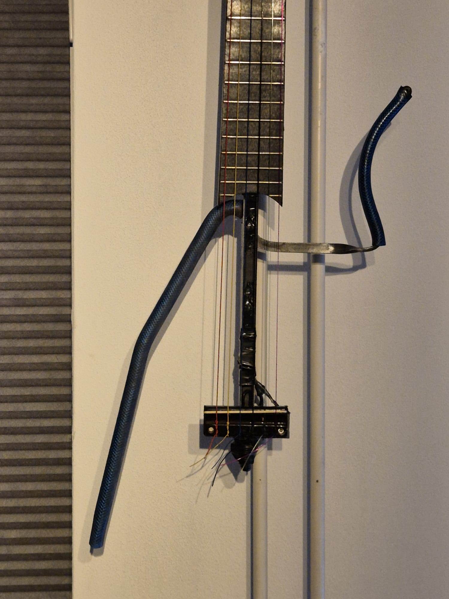
//======================================================================================================================================================
void rollinghumidEN()
{
int Stemp = dht.readHumidity();// Get data from the temp and humid sensor
String Stotal=” The relative humidity is “+String(Stemp)+” percent,”; //define the humid string to be rolled
runscreen(Stotal);
}
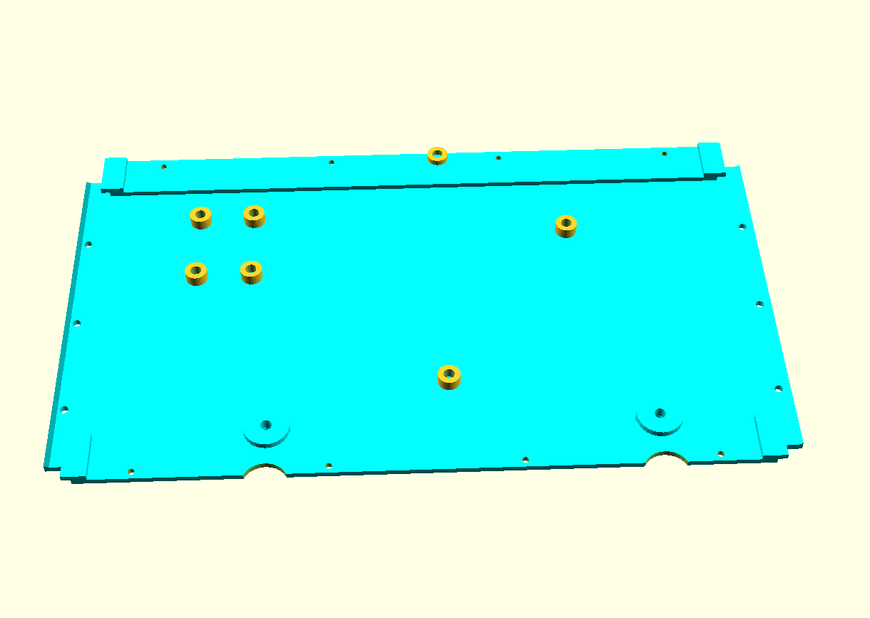
//======================================================================================================================================================
void rollingTempENF()
{
float temperature = 32+ (1.8*(bmp085GetTemperature(bmp085ReadUT()))); // calculate to Fahrenheit= ((Celsius x 1.8) + 32)

String Stotal= ” the temperature is ” + String(temperature,1)+ ” degrees Fahrenheit,” ; //define the string to be rolled
runscreen (Stotal);
}
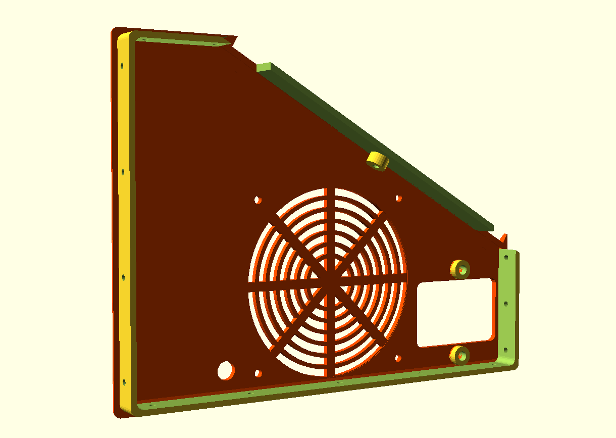
//======================================================================================================================================================
void rollingTempENC()
{
float temperature = bmp085GetTemperature(bmp085ReadUT()); // Celsius

String Stotal= ” (” + String(temperature,1)+ ” degrees Celsius),” ; //define the string to be rolled
runscreen (Stotal);
}
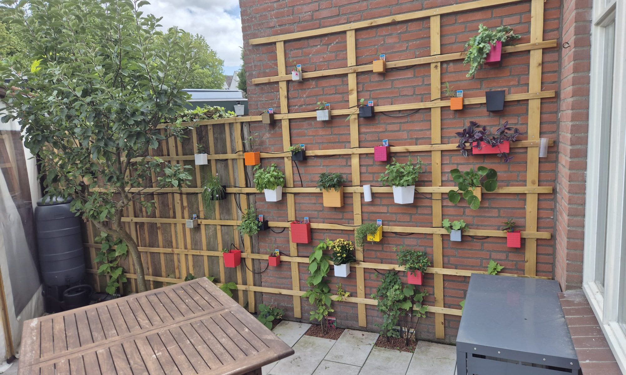
//======================================================================================================================================================
void rollingPressureEN()
{
float pressure = bmp085GetPressure(bmp085ReadUP()); // 100 pascal = 1 millibar
float pressure2 = float (pressure/100);
String Stotal= ” the airpressure is ” + String(pressure2) + ” hPa,”; //define the string to be rolled
runscreen (Stotal);
}
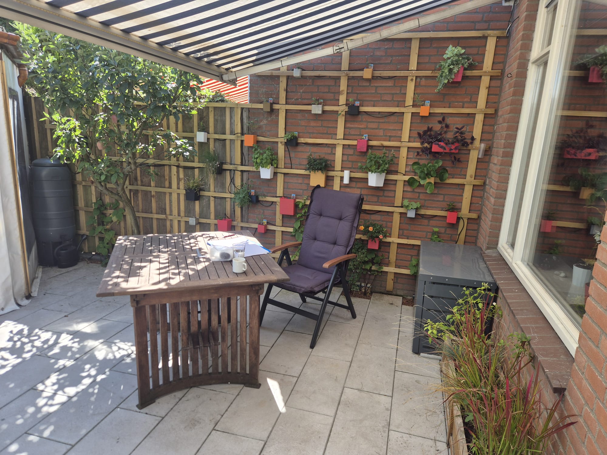
//======================================================================================================================================================
void rollingHeightEN()
{
float pressure = (bmp085GetPressure(bmp085ReadUP())/100); // 100 pascal = 1 millibar
int altitude = calcAltitude(pressure*100); //Uncompensated calculation – in Meters
String Stotal= ” the fictive height is ” + String (altitude) + ” meters “; //define the string to be rolled
runscreen (Stotal);
}

//======================================================================================================================================================
// Stores all of the bmp085’s calibration values into global variables
// Calibration values are required to calculate temp and pressure
// This function should be called at the beginning of the program
void bmp085Calibration()
{
ac1 = bmp085ReadInt(0xAA);
ac2 = bmp085ReadInt(0xAC);
ac3 = bmp085ReadInt(0xAE);
ac4 = bmp085ReadInt(0xB0);
ac5 = bmp085ReadInt(0xB2);
ac6 = bmp085ReadInt(0xB4);
b1 = bmp085ReadInt(0xB6);
b2 = bmp085ReadInt(0xB8);
mb = bmp085ReadInt(0xBA);
mc = bmp085ReadInt(0xBC);
md = bmp085ReadInt(0xBE);
}

// Calculate temperature in deg C
float bmp085GetTemperature(unsigned int ut){
long x1, x2;

x1 = (((long)ut – (long)ac6)*(long)ac5) >> 15;
x2 = ((long)mc << 11)/(x1 + md);
b5 = x1 + x2;

float temp = ((b5 + 8)>>4);
temp = temp /10;

return temp;
}

// Calculate pressure given up
// calibration values must be known
// b5 is also required so bmp085GetTemperature(…) must be called first.
// Value returned will be pressure in units of Pa.
long bmp085GetPressure(unsigned long up){
long x1, x2, x3, b3, b6, p;
unsigned long b4, b7;

b6 = b5 – 4000;
// Calculate B3
x1 = (b2 * (b6 * b6)>>12)>>11;
x2 = (ac2 * b6)>>11;
x3 = x1 + x2;
b3 = (((((long)ac1)*4 + x3)<<OSS) + 2)>>2;

// Calculate B4
x1 = (ac3 * b6)>>13;
x2 = (b1 * ((b6 * b6)>>12))>>16;
x3 = ((x1 + x2) + 2)>>2;
b4 = (ac4 * (unsigned long)(x3 + 32768))>>15;

b7 = ((unsigned long)(up – b3) * (50000>>OSS));
if (b7 < 0x80000000)
p = (b7<<1)/b4;
else
p = (b7/b4)<<1;

x1 = (p>>8) * (p>>8);
x1 = (x1 * 3038)>>16;
x2 = (-7357 * p)>>16;
p += (x1 + x2 + 3791)>>4;

long temp = p;
return temp;
}

// Read 1 byte from the BMP085 at ‘address’
char bmp085Read(unsigned char address)
{
unsigned char data;

Wire.beginTransmission(BMP085_ADDRESS);
Wire.write(address);
Wire.endTransmission();

Wire.requestFrom(BMP085_ADDRESS, 1);
while(!Wire.available())
;

return Wire.read();
}

// Read 2 bytes from the BMP085
// First byte will be from ‘address’
// Second byte will be from ‘address’+1
int bmp085ReadInt(unsigned char address)
{
unsigned char msb, lsb;

Wire.beginTransmission(BMP085_ADDRESS);
Wire.write(address);
Wire.endTransmission();

Wire.requestFrom(BMP085_ADDRESS, 2);
while(Wire.available()<2)
;
msb = Wire.read();
lsb = Wire.read();

return (int) msb<<8 | lsb;
}

// Read the uncompensated temperature value
unsigned int bmp085ReadUT(){
unsigned int ut;

// Write 0x2E into Register 0xF4
// This requests a temperature reading
Wire.beginTransmission(BMP085_ADDRESS);
Wire.write(0xF4);
Wire.write(0x2E);
Wire.endTransmission();

// Wait at least 4.5ms
delay(5);

// Read two bytes from registers 0xF6 and 0xF7
ut = bmp085ReadInt(0xF6);
return ut;
}

// Read the uncompensated pressure value
unsigned long bmp085ReadUP(){

unsigned char msb, lsb, xlsb;
unsigned long up = 0;

// Write 0x34+(OSS<<6) into register 0xF4
// Request a pressure reading w/ oversampling setting
Wire.beginTransmission(BMP085_ADDRESS);
Wire.write(0xF4);
Wire.write(0x34 + (OSS<<6));
Wire.endTransmission();

// Wait for conversion, delay time dependent on OSS
delay(2 + (3<<OSS));

// Read register 0xF6 (MSB), 0xF7 (LSB), and 0xF8 (XLSB)
msb = bmp085Read(0xF6);
lsb = bmp085Read(0xF7);
xlsb = bmp085Read(0xF8);

up = (((unsigned long) msb << 16) | ((unsigned long) lsb << 8) | (unsigned long) xlsb) >> (8-OSS);

return up;
}
// xxxxxxxxxxxxxxxxxxxxxxxxxxxxxxxxxxxxxxxxxxxxxxxxxxxxxxxxxxxxxxxxxxxxxxxxxxxxxxxxxxxxxxxxxxxxxxxxxxxxxxxxxxxxxxxxxxxxxxx
void writeRegister(int deviceAddress, byte address, byte val)
{
Wire.beginTransmission(deviceAddress); // start transmission to device
Wire.write(address); // send register address
Wire.write(val); // send value to write
Wire.endTransmission(); // end transmission
}

int readRegister(int deviceAddress, byte address){

int v;
Wire.beginTransmission(deviceAddress);
Wire.write(address); // register to read
Wire.endTransmission();

Wire.requestFrom(deviceAddress, 1); // read a byte

while(!Wire.available()) {
// waiting
}

v = Wire.read();
return v;
}

float calcAltitude(float pressure){

float A = pressure/101325;
float B = 1/5.25588;
float C = pow(A,B);
C = 1 – C;
C = C /0.0000225577;

return C;
}

//XXXXXXXXXXXXXXXXXXXXXXXXXXXXXXXXXXXXXXXXXXXXXXXXXXXXXXXXXXXXXXXXXXXXXXXXXXXXXXXXXXXXXXXXXXXXXXXXXXXXXXXXXXXXXXXXXXXXXXXXXXXXXXXXXXXXXXXXXXXXXXXXXXX
void switches()
/* the intent here is to use a couple of hardware switches to set all parameters of the system, so you don’t need to update it with the PC.
The systems becomes independent in this way and possibly it can be a sellable item then.

There will be 3 switches: Select , Up and Down. If there is enough room, I will connect them all three to available inputs:
A1= Select,
D9= Up and
D7= Down

The structure is for Select to halt the running programs through the interrupt that is built in the wait void!
Once you are in the switches void the structure is to g through setup with Up and Down, choose the appropriate setting ans Select is, after which you
can again select a new option if available and so on.

I will try to make a function that allows you to press Up and Down at the same time to return immediately or to use is as a reset possibility…

Up and down could also be used as up/down time/date/others by pressing where long press fastens the speed of change…
*/

{

//main menu select main functions 1 clock set,2 date set,3 language,4 speed,5 appearance: short/long/playfull,6 priority : more time/ more weather/ more fun, 7 update

// this variable used to store these switches is integer: MainMenu (1-7)
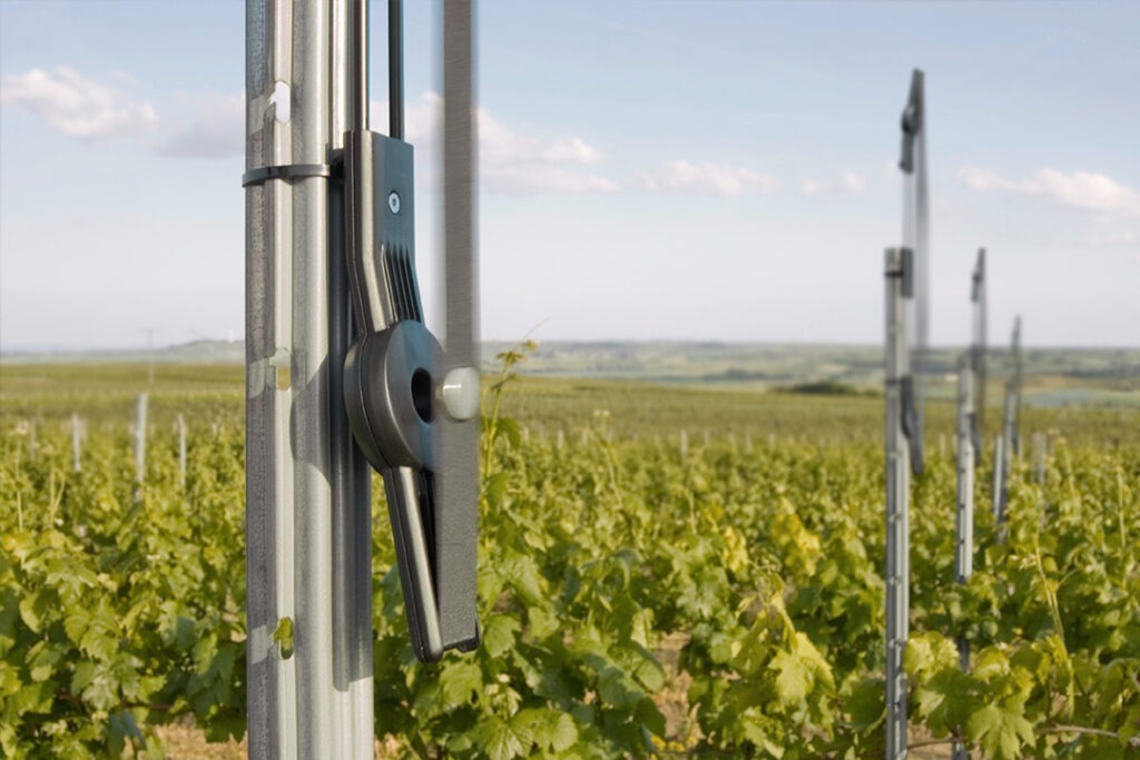
// The choices will be stored in the available flash memory of the DS 1307 so that the system will always restart with the active last settings
// Only the first 8 bytes (0x00 – 0x07) are used by the clock itself while the other 56 bytes can be used as scratchpad RAM, BUT.. on this small board there
// is also 32K of memory available in a small AT24C32 separately addressable Eprom memory!

Select=false; // reset state of Reset button to start

// this is the 1st loop to input and setup
clearscreen();

writescreensmall(” press a”, ” button “, 0);

// delay(5000);

//wait for press on Up, Down or Select
while(1)
{
int valU = digitalRead(UpPIN); // read the input pin
if (valU==LOW) {Up=true; break;} // // if key Up is pressed set a binary state high here
int valD = digitalRead(DownPIN); // read the input pin
if (valD==LOW) {Down=true; break;} // if key Down is pressed set a binary state high here
// int valS = digitalRead(SelectPIN); // read the input pin
// if (valS==LOW) {Select=true; break;} // if key Select is pressed set a binary state high here
}
clearscreen();
//xxxxxxxxxxxxxxxxxxxxxxxxxxxxxxxxxxxxxx

if (Up==true){
Up=false;
// this is the 2nd loop to input and setup
clearscreen();
writescreensmall(” time “, “settings”,0);
delay(2000);

//wait for press on Up or Down
while(1)
{
int valU = digitalRead(UpPIN); // read the input pin
if (valU==LOW) {Up=true; break;} // // if key Up is pressed set a binary state high here
int valD = digitalRead(DownPIN); // read the input pin
if (valD==LOW) {Down=true; break;} // if key Up is pressed set a binary state high here
int valS = digitalRead(SelectPIN); // read the input pin
if (valS==LOW) {Select=true; break;} // if key Select is pressed set a binary state high here
}
clearscreen();
}

//xxxxxxxxxxxxxxxxxxxxxxxxxxxxxxxxxxxxx

if (Down==true){
Down=false;
// this is the 2nd loop to input and setup
clearscreen();
writescreensmall(” date “, “settings”,0);

delay(2000);

//wait for press on Up or Down
while(1)
{
int valU = digitalRead(UpPIN); // read the input pin
if (valU==LOW) {Up=true; break;} // // if key Up is pressed set a binary state high here
int valD = digitalRead(DownPIN); // read the input pin
if (valD==LOW) {Down=true; break;} // if key Up is pressed set a binary state high here
int valS = digitalRead(SelectPIN); // read the input pin
if (valS==LOW) {Select=true; break;} // if key Select is pressed set a binary state high here
}
clearscreen();
}

//xxxxxxxxxxxxxxxxxxxxxxxxxxxxxxxxxxxxx
if (Select=true) {Select=false; Up=false; Down=false; return;}
if (Up=true) {Up=false; switches();}
if (Down=true) {Down=false; switches();}
//else Select=true, this must be better structured!
//else break;

//xxxxxxxxxxxxxxxxxxxxxxxxxxxxxxxxxxxxx
// write the dataword in memory that will be used after this as settings for all variables, and when restarted read from mem for the same purpose…
// use the mem from the DS1307, extra chip on it with 32Kbit= 4kByte
low=0x00;
byte dataword[]={“05100000000testJMWG”};
//pos 1 (not 0) plus 48 is wait, etcetera…. IT IS an array of chars!
// can be written per character, is simpler than first build an array…

for (int i=0;i<=20;i++)
{
Wire.beginTransmission(0x50);
Wire.write(high);
Wire.write(low);
Wire.write(dataword[i]);
Wire.endTransmission();
delay(5);
low++;
}

//READ the memory of the AT24C32 (just used for debugging)
low=0x00;
// Serial.println();
for (int i=0;i<=20;i++)
{
Wire.beginTransmission(0x50);
Wire.write(high);
Wire.write(low);
Wire.endTransmission();
Wire.requestFrom(0x50 ,1);
char data=Wire.read();
delay(5);
// Serial.print(“DATA “);
// Serial.print(data);
// Serial.print(” LO ADD “);
// Serial.println(low);
// delay(10);
low++;
}

// Serial.println();
// Serial.print(“wait= “);
// Serial.print(wait);

// the values of the settings will be written in AT24C32 register and will be read in Setup void, every time the device (re)starts
// the values are minus 48 due to the caharcter set in memory, ascii table starts at 0 as int48!
// wait, integer between 0 and 9==>8 to 18 (+8) position low 1
// typeofclock, small clock or big clock 0 or 1 position low 2
// fun, with fun or just readouts 0 or 1 position low 3
// minormax, minimum screen or all of it 0 or 1 position low 4

Select=false; // reset state of 3 buttons to start
Up=false; // reset state of 3 buttons to start
Down=false; // reset state of 3 buttons to start

}