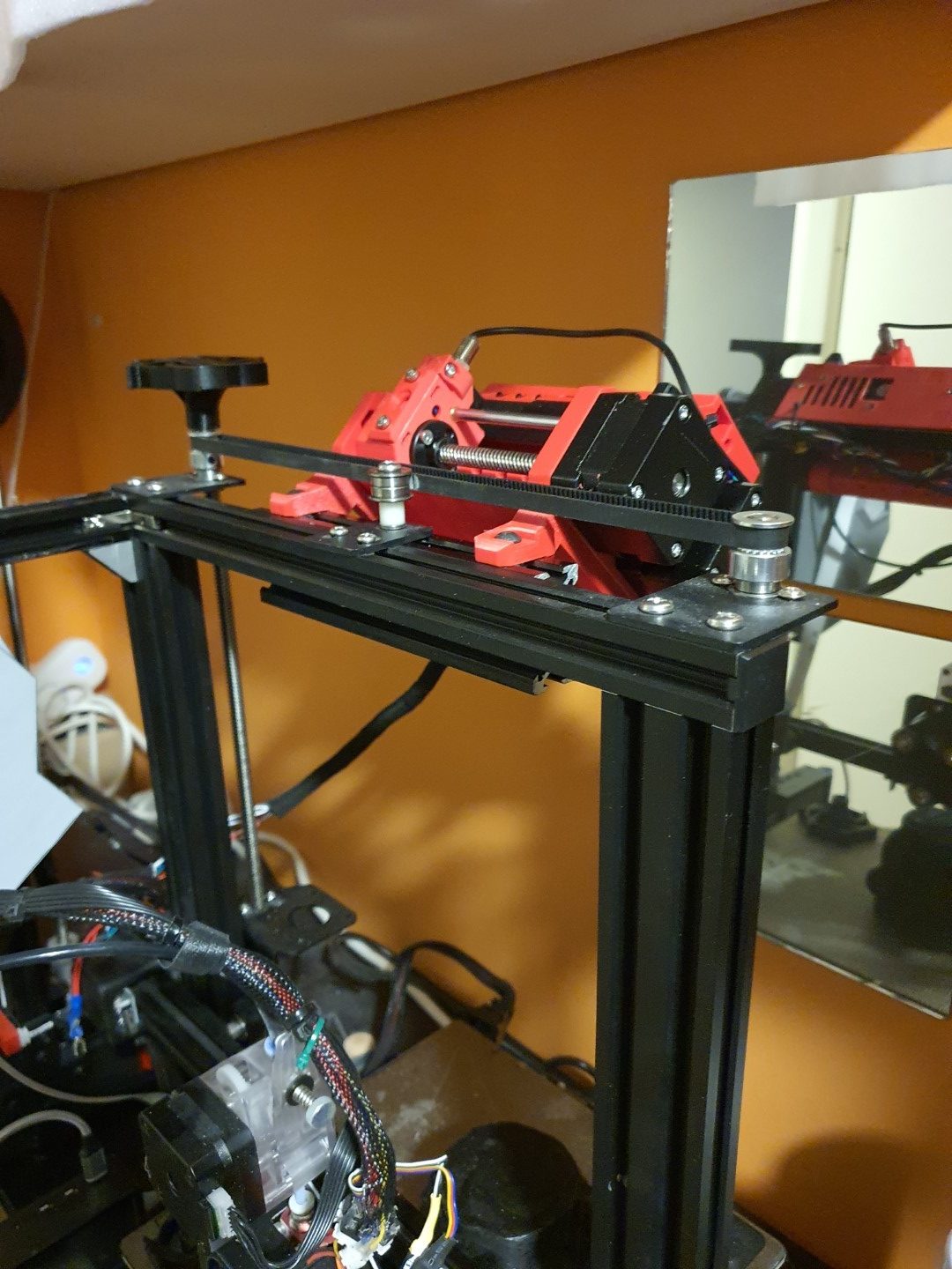
In 2020 I upgraded my Ender 3 with synchronised Z-axes and a new motherboard, the SKR Mini E3 V2.1.
The Ender 3 is very reliable and has been equipped with a direct drive bondtech extruder but still has the original hotend.
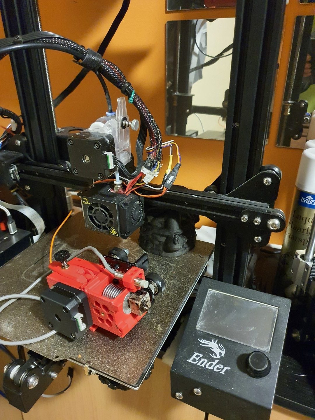
I chose the Ender3 to be the 3d printer on which I will attach the MMU2S. This also means that I will have to exchange the hotend/extruder combination with a Prusa Mk3S version.
Started this on May 4th, 2021. Only the printed parts were needed, all other parts were already available through sourcing form a.o. Ali. I printed everything in ABS, mostly red. For this I used 2 machines: The Twotrees Sapphire pro with enclosure for black ABS and the Voron 2.3 (300) for red ABS.
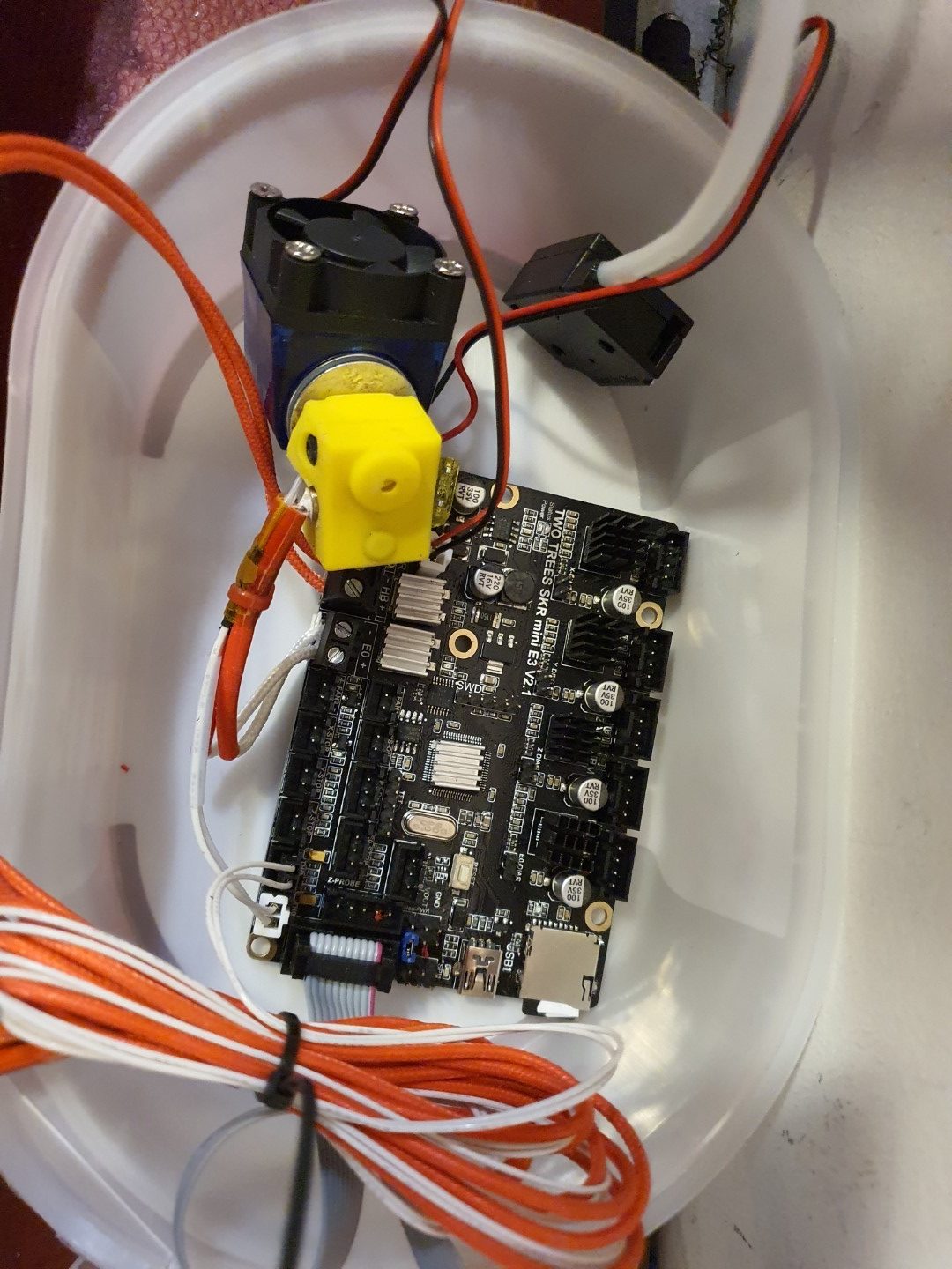
The motherboard that is also in the Ender3, SKR mini E3 V2.1. I used this setup to test the MMU hard- and software together with the SKR mini E3 motherboardThe MMU2S on top of the Ender3, just next to the 6mm belt that connects both Z-leadscrewsThe bondtech Prusa MK3S hotend/extruder combination, mounted on a 2020 mounting plate for the Ender3
There is a firmware version for the SKR mini E3 V2.1 on Github that makes use of the MMU2S. I downloaded this version and uploaded it to the board via visual studio code maker, all works well in the test setup. Some tweaking was needed in configuration.h and in the advance config, since I am using the S-version of the MMU2 and the filament sensor was not standard ON. And- it appears that the communication port needs to change to the 2nd port. You can see it all at the Reddit page, the additional changes to the published config files are these (thnx to fixel112):
Excerpt from Configuration.h:
#define SERIAL_PORT -1
#define SERIAL_PORT_2 2 <————— This has been the issue. Uncomment that line.
#define BAUDRATE 250000
Excerpt: Configuration_adv.h
#if ENABLED(PRUSA_MMU2)
// Serial port used for communication with MMU2.
// For AVR enable the UART port used for the MMU. (e.g., mmuSerial)
// For 32-bit boards check your HAL for available serial ports. (e.g., Serial2)
//#define MMU2_SERIAL_PORT 2
#define MMU2_SERIAL MSerial2
//#define MMU2_RST_PIN 23
// Enable if the MMU2 has 12V stepper motors (MMU2 Firmware 1.0.2 and up)
//#define MMU2_MODE_12V
// G-code to execute when MMU2 F.I.N.D.A. probe detects filament runout
#define MMU2_FILAMENT_RUNOUT_SCRIPT “M600”
…
#define MMU2_DEBUG // Write debug info to serial output
#endif // PRUSA_MMU2
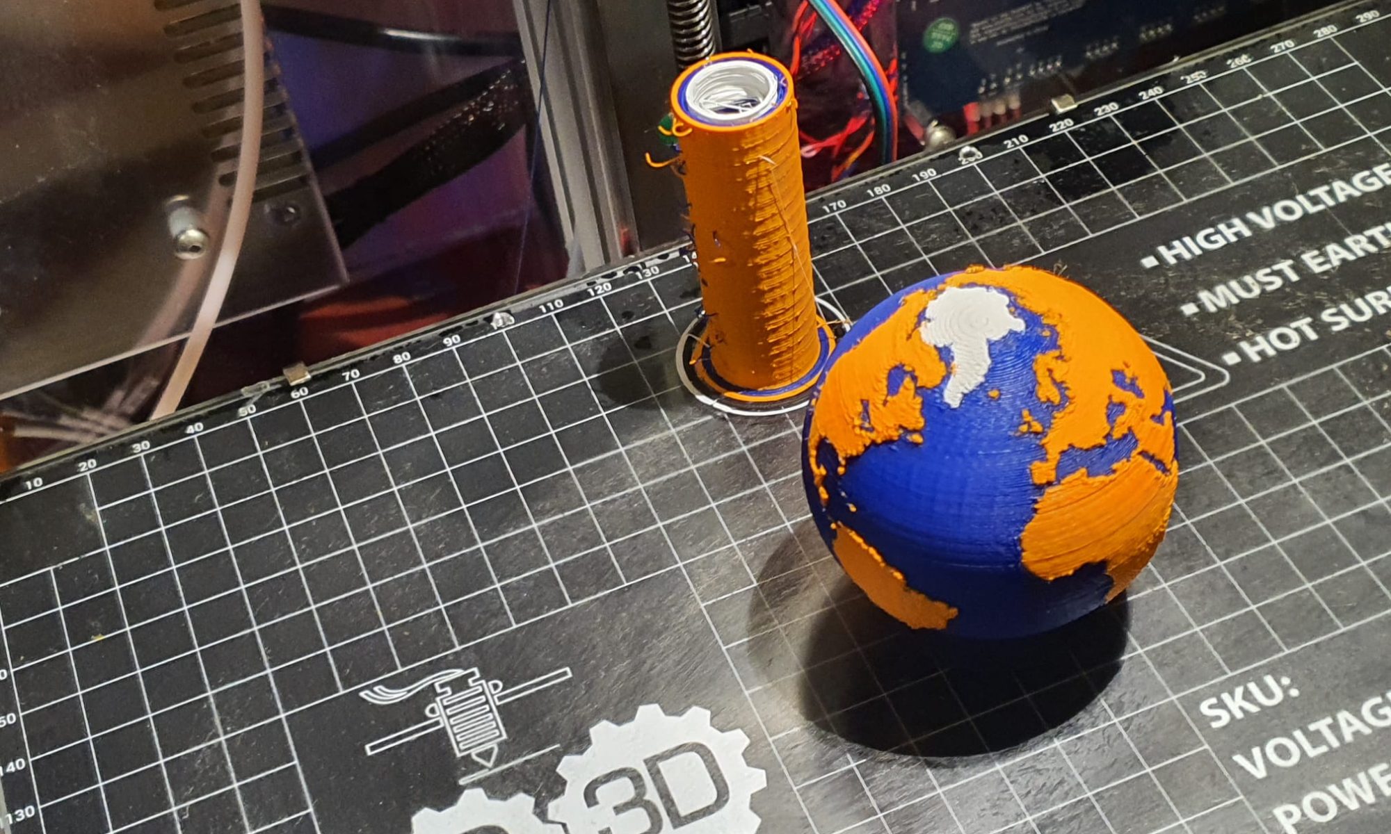
Next is to put everything physically on the Ender, and exchange the hotend/extruder. Then, the settings for the extrusion lengths will have to be determined. And- the buffer for the filament between the MMU2S and the filament spools has to be installed. As soon as I have it all properly installed, more pictures will follow!
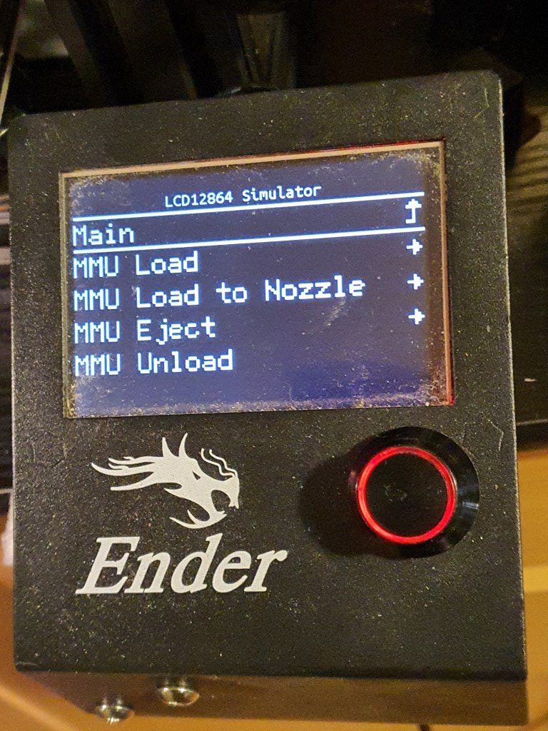
I discovered that the dual display I now use for the Ender3 will only work for Marlin LCD and no longer for TFT, since the serial TFT pins will be used to drive the MMU2S unit. I exchanged the TFT/LCD unit with the original Ender3 LCD, I kept this in storage and tested it today with the Ender mini E3 V2.1 , it works very well!
The twotrees SKR Mini E3 V2.1 motherboard is really perfect for the combination with the MMU2S and the new filament sensor in the new hotend/extruder. The firmware has been updated to include the MMU2S and the AUX’s serial that was previously used for the TFT screen is now in use by the MMU! It all works!!!
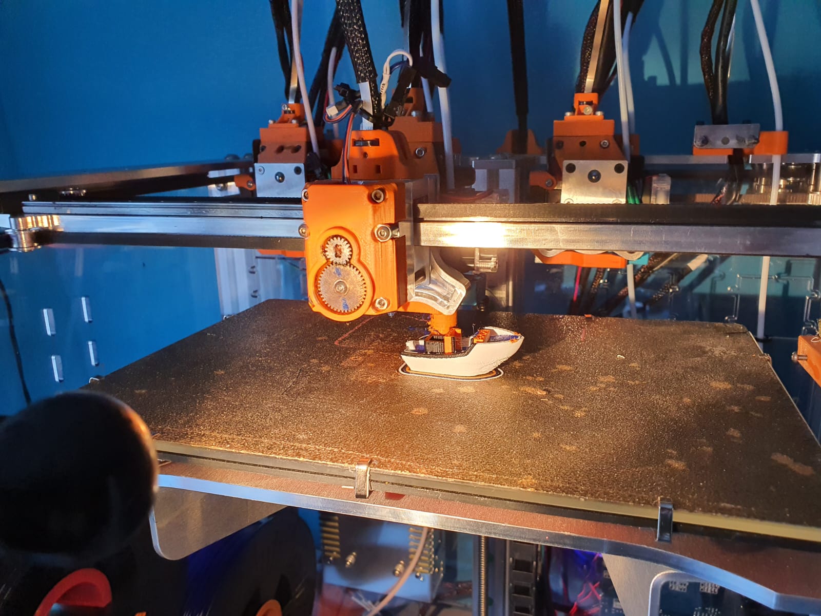
Now the next thing was to get the new extruder, F.I.N.D.A. and the filament sensr to work properly.
That took some time and next on the agenda is the filament management.
I already decided to go with the original Prusa filament box with plates to hold the retracted filament for all 5 spools. The spools themselves will hang at the wall, behind the printer. I don’t have space for standing spoolholders. Underneath the spools the filament box with plates gets its place on the wall and from there the 5 PTFE tubes will run to the MMU!