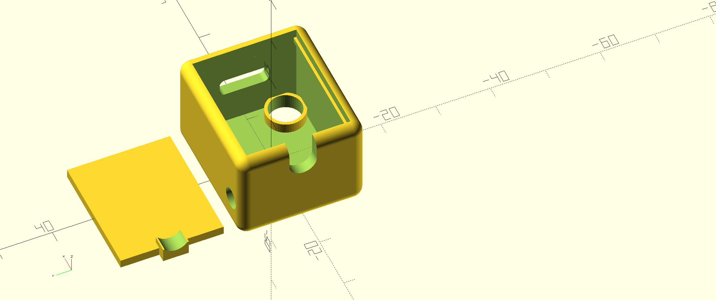
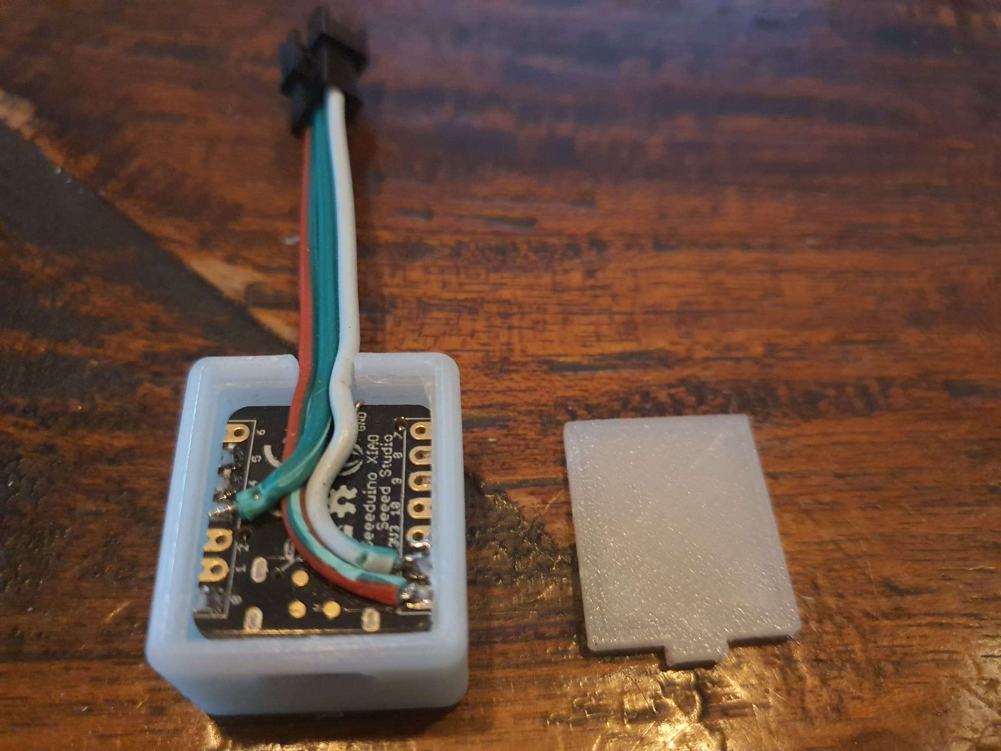
This is a tiny case for my XMAS LED projects, with RGB leds WS2811 or 2812B.
Please donate $1 to my paypal account if you use (parts of) my designs so I can continue to share nice stuff for you to download
download STL file small case Xiao nano&LDR&DS3231 with LDR hole 20241127 V14
Please donate $1 to my paypal account if you use (parts of) my designs so I can continue to share nice stuff for you to download
I also added a mini board with a clock chip, DS3231 to the XIAO USB-C board, and an LDR to make the RGB’s brighter when they are used during daylight conditions. An example Arduino code with clock function is HERE.
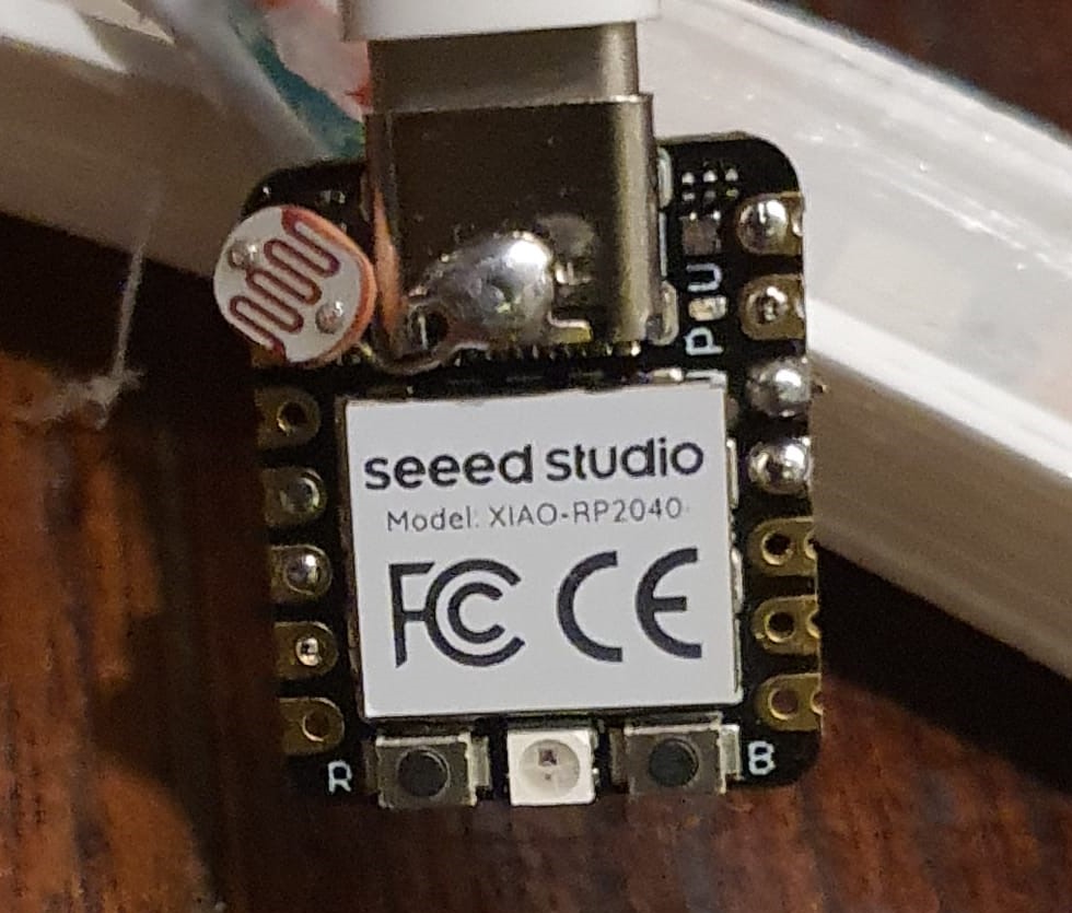
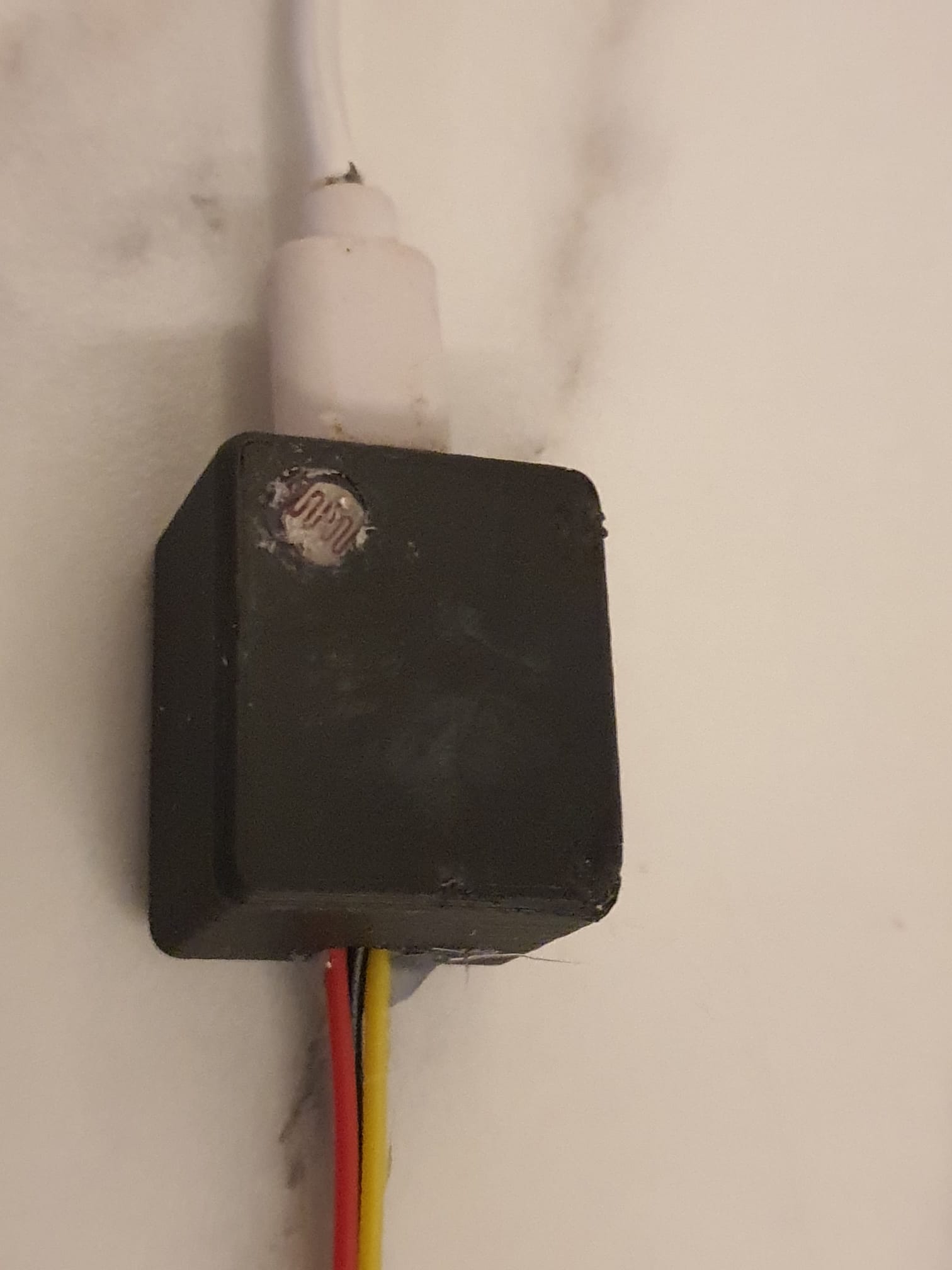
The LDR is mounted on the XIAO board’s top on A0 and GND, so it can be flush to the outer skin of the case through the dedicated LDR hole. Be aware to also add a 10K resistor between A0 and 3v3 since this board does not have programmable PULL-UP resistors.
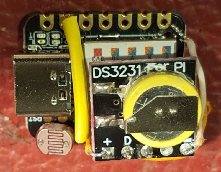
The mini DS3231 clock board is connected to the XIAO’s pins A4 and A5, 3V3 and GND. There is also a small battery on the little clock board., so the time will always be available. I mounted the clock board so that the DS3231 chip is flat against the RP2040 chip. Then, the Data in and out of the clock board are then facing D4 and D5 of the RP2040. I used 2 Arduino pin headers to connect these data lines together. 3V3 aand GND are connected between the boards using thin wires.
Output to the LED’s is on pin 3 (D3). For the LEDS, also VCC and GND are required, either from the XIAO board’s VCC and GND pins or from the board’s 5V power supply +5V and GND connections. The LDR is mounted making use of a little stud, cut off from the tiny clock board since they have to be removed from the clock board anyway. This makes the LDR fit the box’s LDR hole perfectly.
For resetting an DR2040, a small hole is made to reach the little BOOT switch. This is sometimes required since the RP2040 can get bricked when a non-working void is uploaded. Push the boot butten when powering up, release the button and the RP2040 is in recovery status. Up[load a simple program and the RP2040 will resume normal functioning. Then, the normal COM port will work again an normal flashing is again possible.
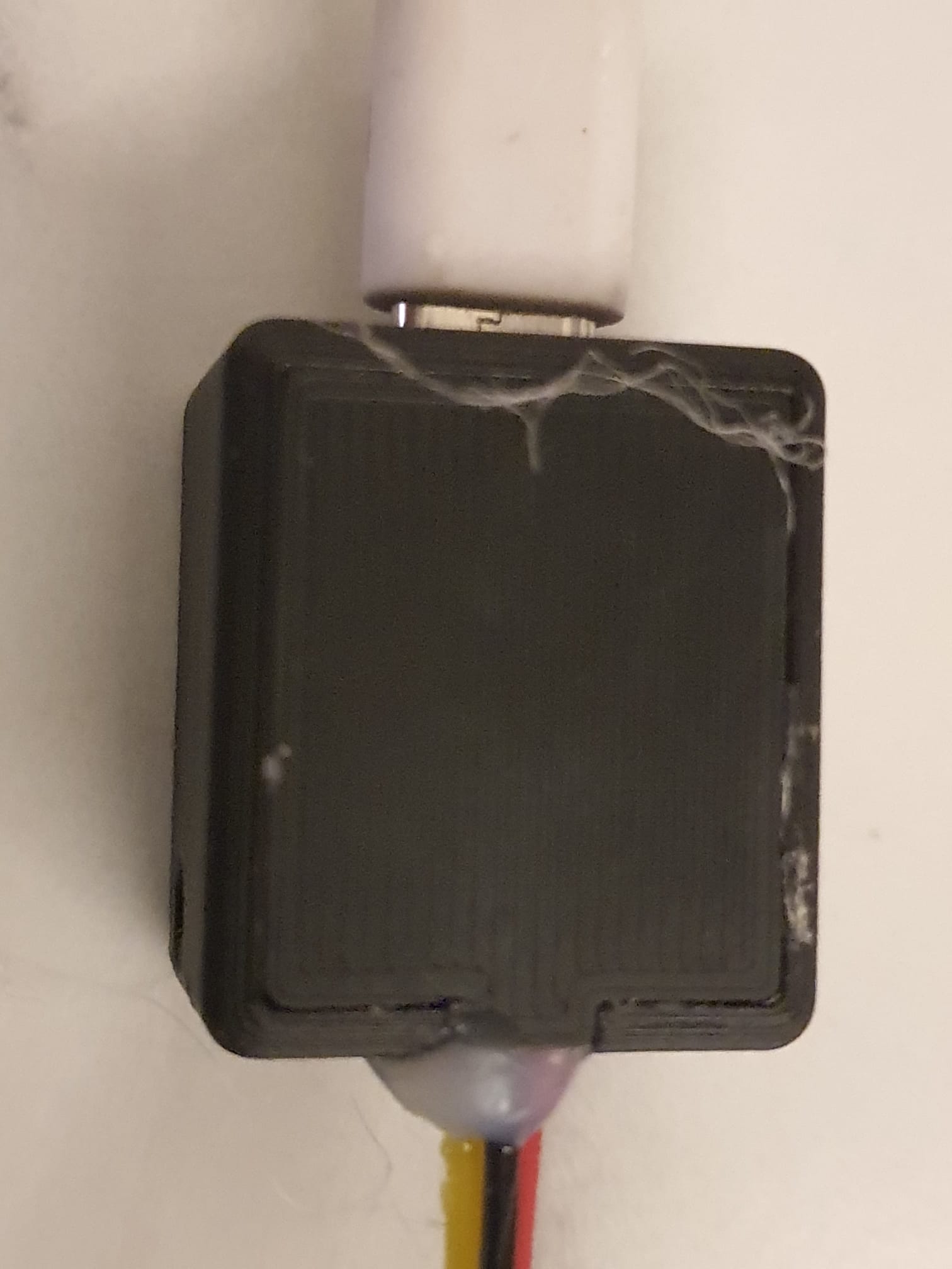
The case has a snap-on lid that will also fixate the outlet cable for the RGB LED’s.
Please donate $1 to my paypal account if you use (parts of) my designs so I can continue to share nice stuff for you to download
