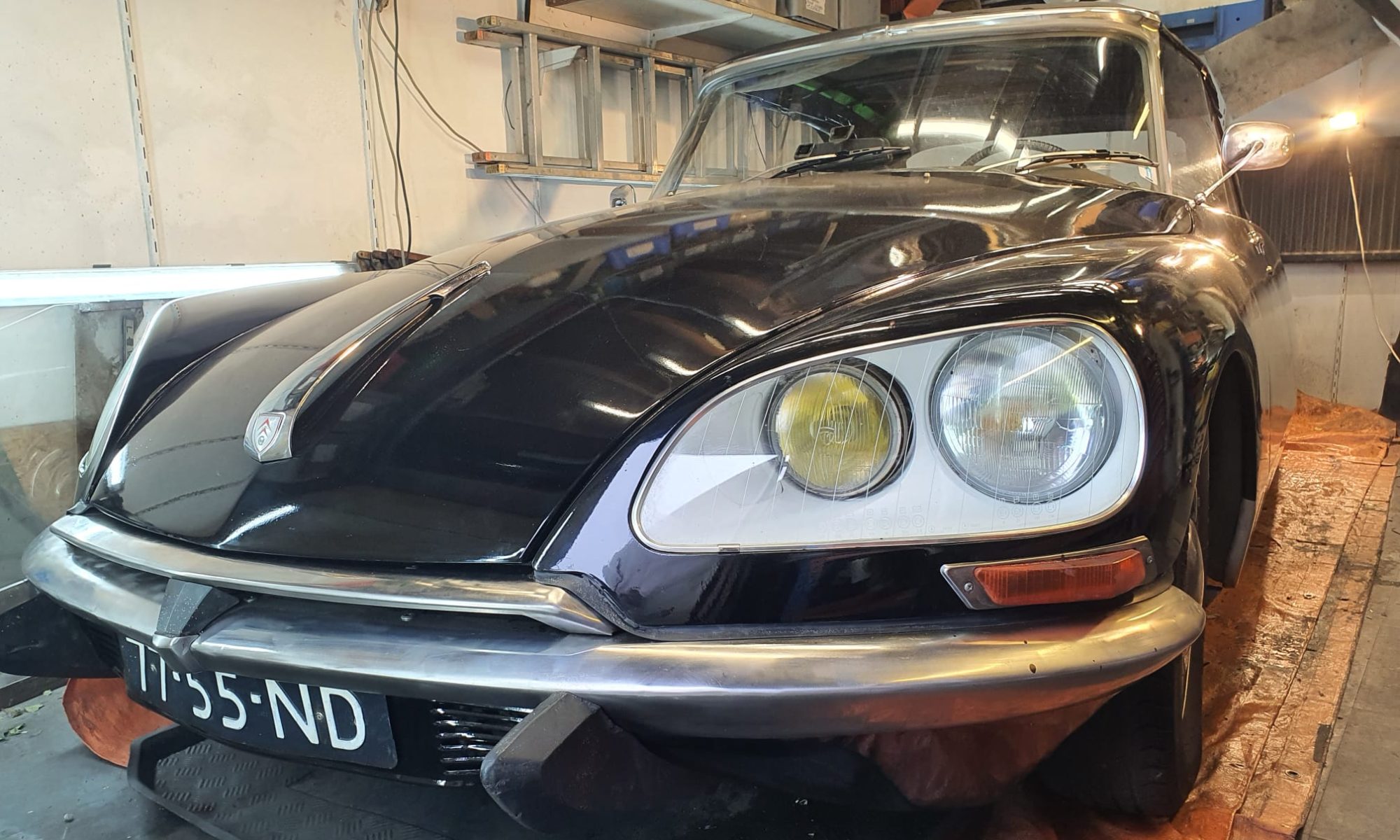
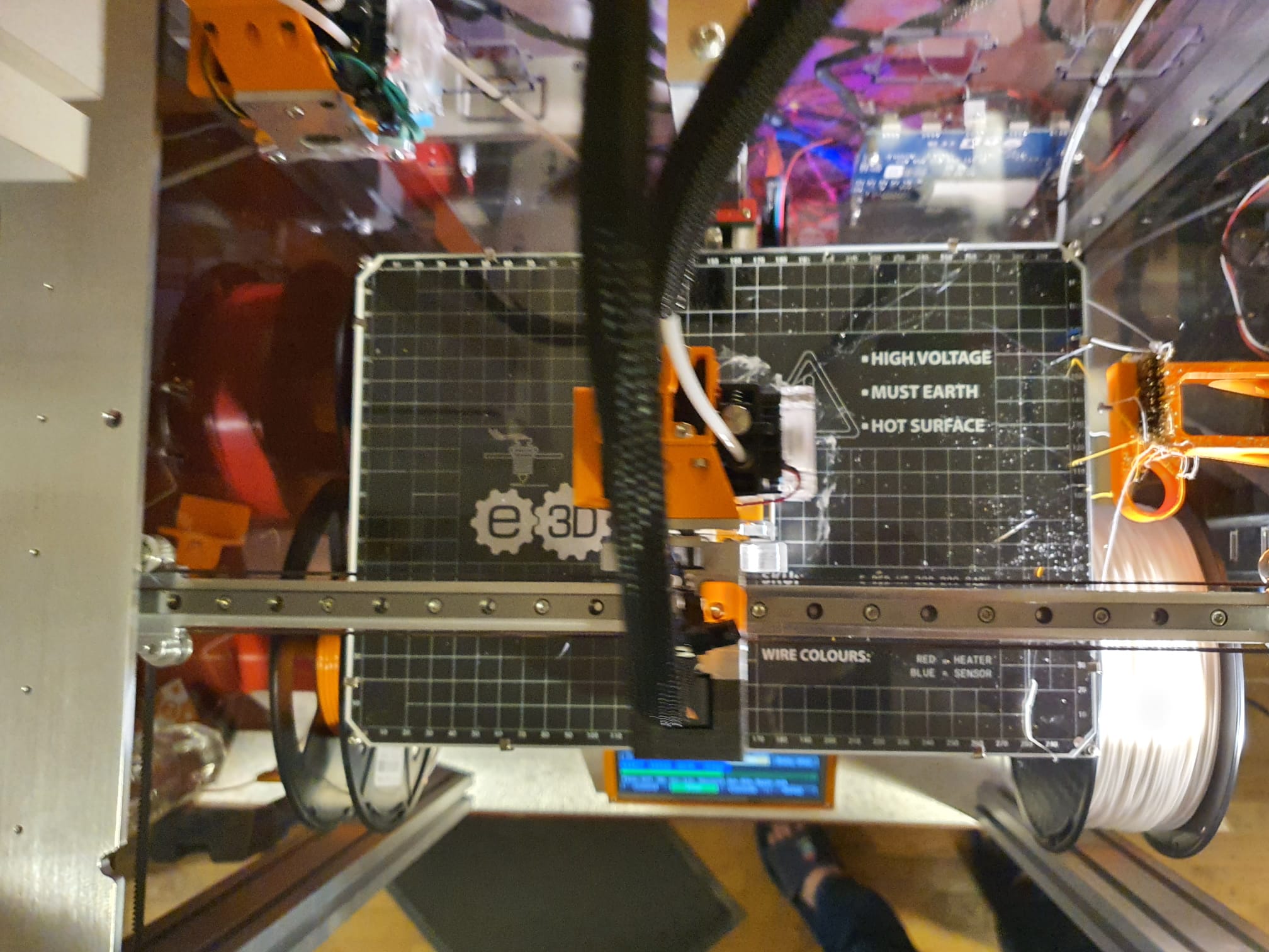
HOW DOES IT WORK WITH THE E3D TOOLCHANGER?
The system whereby the E3D tool changer determines the Z value of the four tools is fixed in the preset system files. This means that you perform a Z homing paper test for each tool to determine the deviation of each tool relative to T0, which is the leftmost tool. You enter the result in the config file as the Z-value for each tool, whereby I usually use “0” for T0 and the general Z-probe value, which I determine as the difference between the manual probe on the carriage and the nozzle height of T0.
First, you need to determine the Z deviation of T0 relative to the Z value of the carriage that picks up the tools. This is done by homing the bare carriage with a Z probe switch under the carriage to Z value = 0 on the bed.
Then you do a tool pickup from T0 and measure the height of T0 as the Z value. You then enter that value as the probe value in your config file. I find all this rather cumbersome, especially because everything changes when you change a nozzle, for example.
Below video: E3D toolchanger homing the carriage and do the tool pickup
DESIRED SITUATION
Ideally, I would prefer to have each of the four tools, i.e. T0 to T3, home X, Y and Z every time a new object gets printed, and in this manner you can also just select any tool to do the bed mesh.
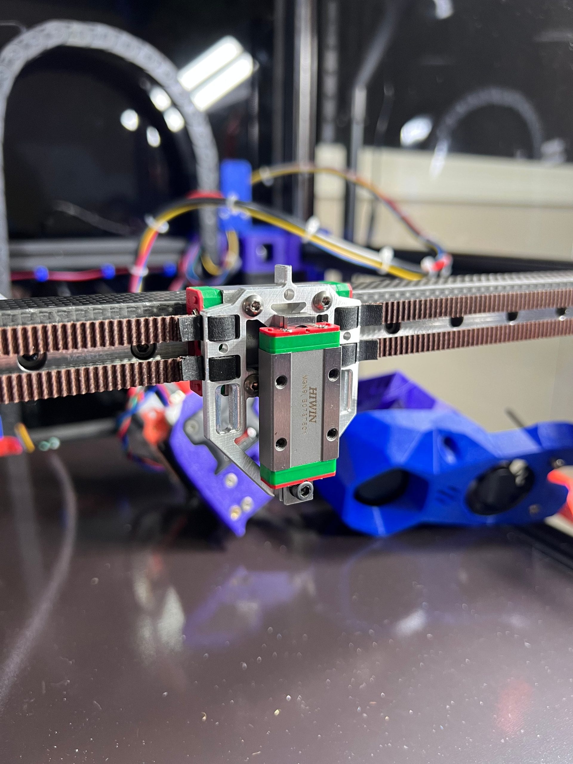
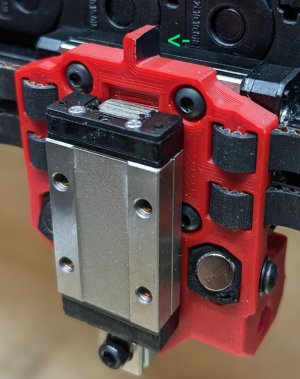
You then take those four Z values as the Z=0 value per tool, and you’re done. This works great with the Voron that I run with TAP Z-homing! It doesn’t matter what you do with your bed or your hot end, gantry, etc. It doesn’t matter because the nozzle is used as a mechanical Z-homing tip.
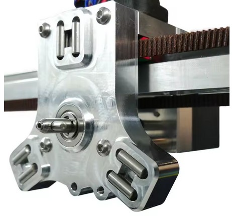
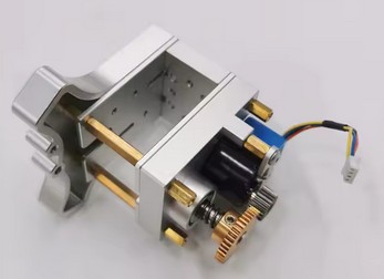
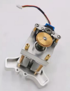
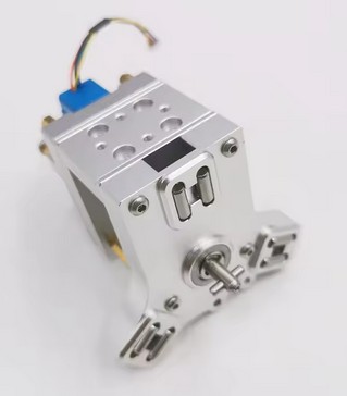
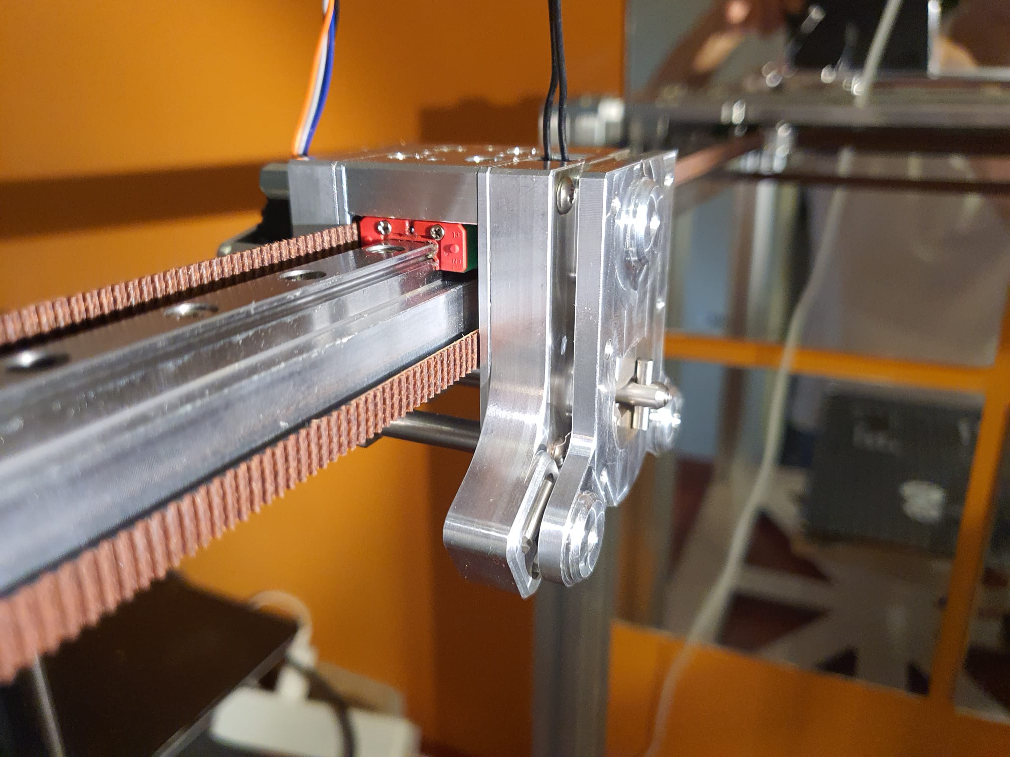
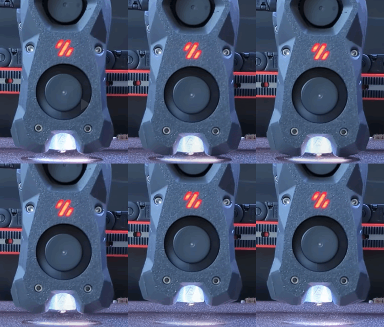
How the TAP function works on a Voron2.4 3D printer
ADDITIONAL: Self-searching tool changer
And while I’m at it: why not make a self-searching tool changer? Roughly set it up with the XYZ coordinates per tool, the last part electronically with a guide system between the pick-up trolley and the tool, and the final fitting with the existing mechanical fitting.
Instead of determining exactly where each tool should be picked up and put away by trial and error, you could use an electronic guidance system to aim precisely at the right tool when it needs to be changed. No more hassle with X-Y settings and homing axes. Because if anything changes as a result of mechanical stress in the frame or due to small deviations from the X and Y homing, picking up and putting away tools will regularly go wrong.
One possible way to do this could be a passage LED/LASER system, such as those used at shop entrances.
.
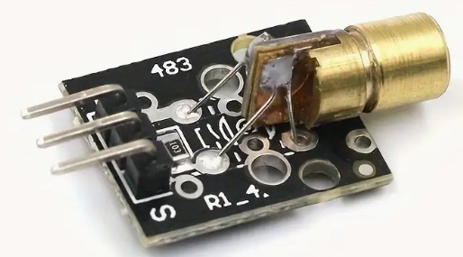
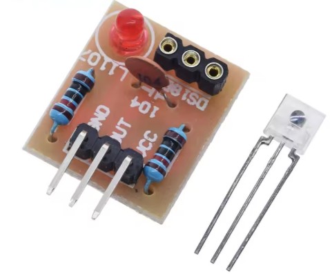
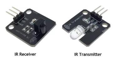
To do this, you use a targeting laser, such as in a levelling system, or an infrared laser with a receiver.
This is placed on top of the X-axis on the moving toolhead and is aimed at the tools, at a 90-degree angle to the X-axis.
You then activate the correct tool you want to move to or pick up as the receiver.
With an X-sweep movement, you can make contact with the receiving tool and then move in a straight line towards the tool until you reach the pick-up point, which is specified in absolute Y value in the configuration file. Sounds like a great development!
ADDITIONAL: Precise XYZ homing of the tools
And I would like to have a way to centre X, Y and Z of each tool nozzle in detail relative to the other tool nozzles, just like with my CNC machines:
With such a head alignment block, you can accurately determine the position of all axes on a CNC machine. First, you need to determine the approximate position of this block, with an accuracy of approximately 1 mm on the X and Y axes.
The alignment block is electrically insulated and works by making contact between the tool tip and the block.
How does homing with an alignment block work?
You programme a centring macro in G-code.
First, you temporarily set the motor power to the lowest possible value to avoid damage if anything is in the way of the moves to be made.
Just as when I regularly do a home-all, with this new method you also set the bed and the relevant tool nozzle to operating mode (e.g. bed at 70 degrees and nozzle at 180 degrees).
Then you do a normal XY homing, which in my case works with limit switches (or optical switches) at the start of the X and Y axes.
A Z-homing action is also necessary unless you do not want to remove the Z-move block that occurs when you have not first homed Z.
Then move the Z-axis up sufficiently to avoid hitting the block.
Next, move to the absolute XY position of the block.
When you are above the block with your tool, home your Z.
Then home on Z+0.3 both -X and +X, and in the middle of -X and +X home -Y and +Y.
The result is the exact position of the centre on the flat Z plane of the alignment block.
Because you know exactly what the position is in relation to the bed centre and from X0, Y0 and Z0, you can translate this directly into the macro and enter the Z0, X0 and Y0 values as absolute values.
It should be possible to home the E3D tool changer tools in this way as well, with Z using the TAP function and X and Y using electrical detection as described above for the CNC milling machines. We will see if and how this will work as a supplement to TAP-Z homing with the current X and Y microswitch homing on the X and Y axes.
CONCLUSION -FOR NOW-
The credo still seems to be: If the E3D tool changer is working, it’s best to leave it alone. That doesn’t suit me at all, because I often move my printers around. And that doesn’t always go well.
So I’m going to look into these issues and, if possible, build something!
