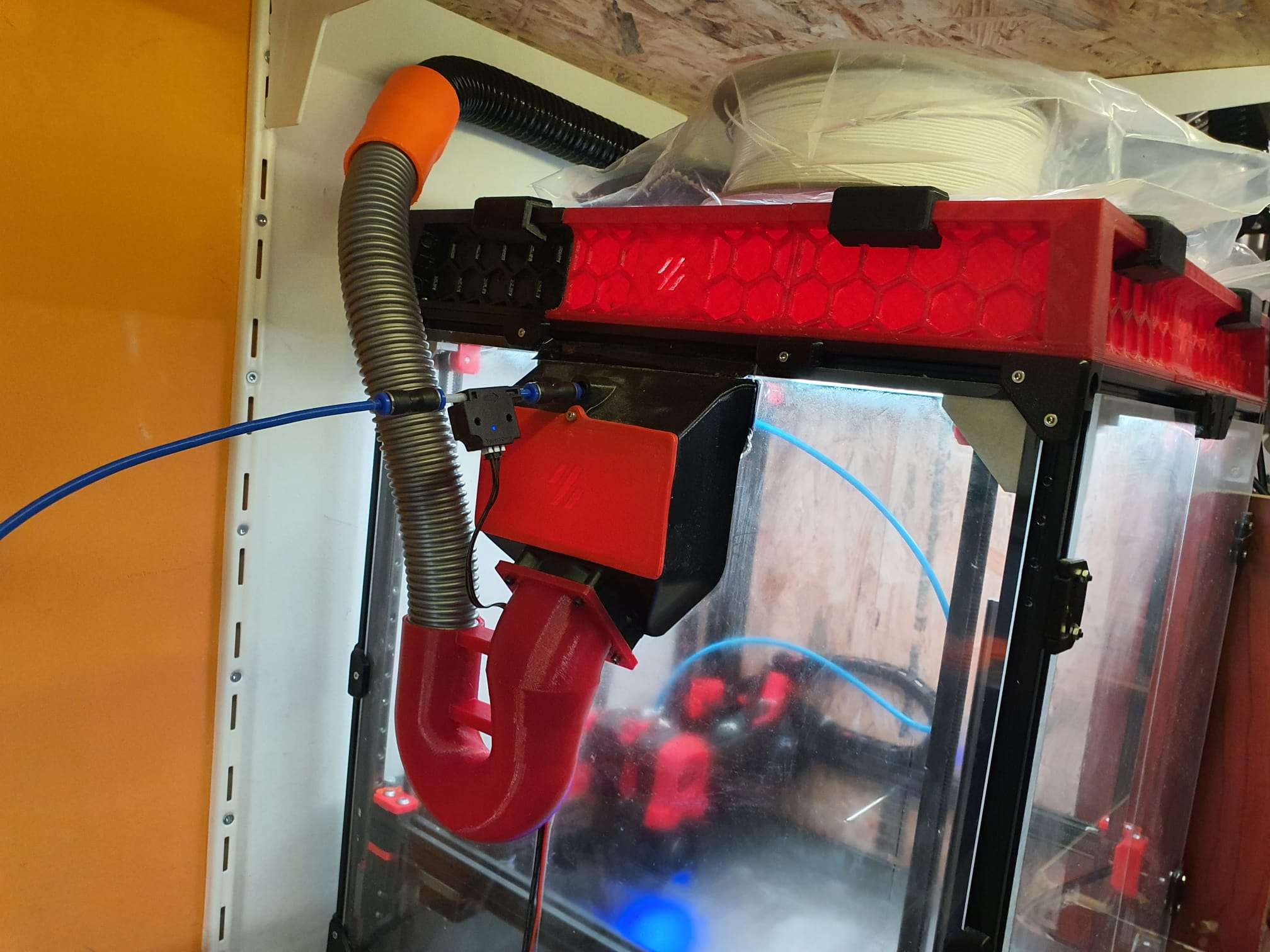
Voron2.4_fanduct_60_flanged_to_2x_40_inner_bent_pipes_45&180deg_V6_20231118 DOWNLOAD STL


3D modeling, scanning and printing


fits regular beer bottles of 330cl
//length regular beer bottle of 330cc is 238mm
//diameter regular 330cc beer bottle is 61mm
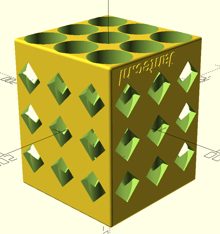
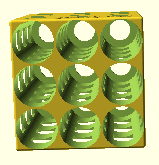
The beer bottle box in 3×3 bottles version measures 238 mm deep and 197mm wide & high.
beer bottles 3×3 fridge rack 2023 04 20
And a revised version that can be printed without support:
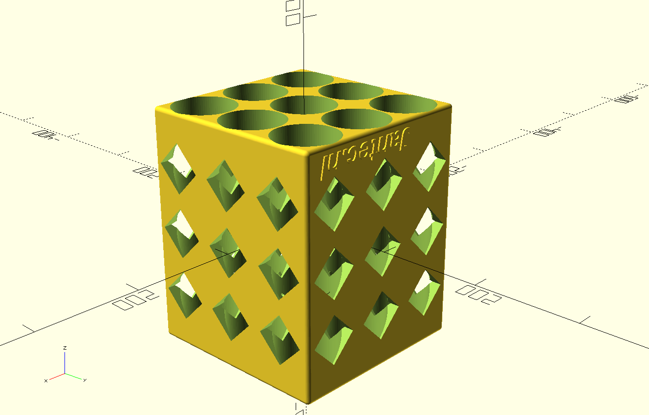 beer bottles fridge rack with 45deg squared side holes 2023 04 20
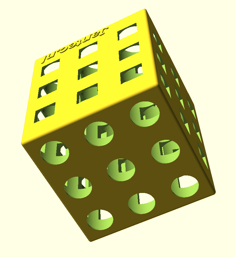
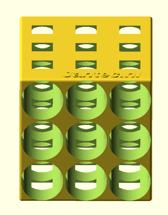
And a short version where the bottlenecks will stick out a bit:
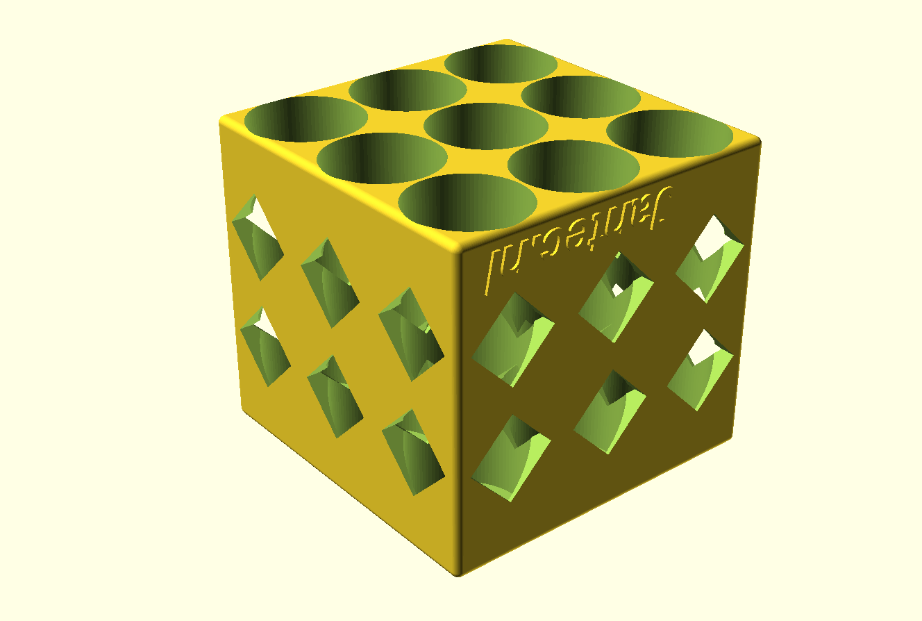 beer bottles SHORT fridge rack with 45deg squared side holes 2023 04 20
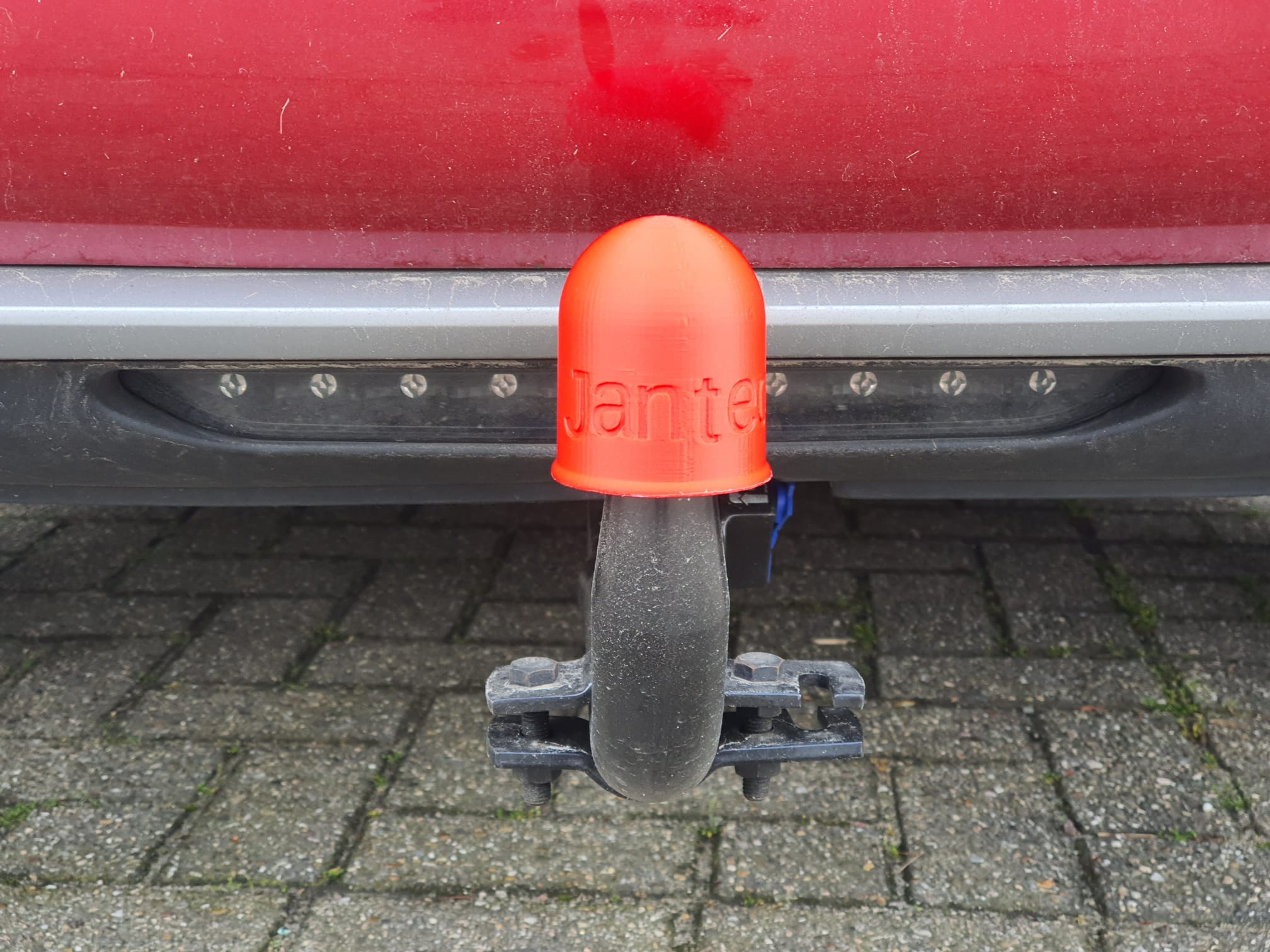
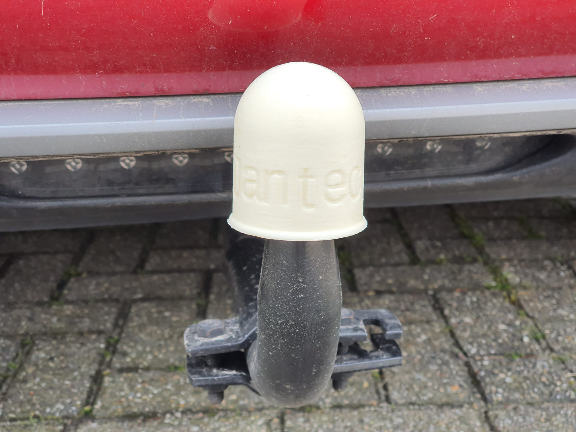
Tow bar ball cover 2-23 05 11 V1 Revd FREE STL DOWNLOAD
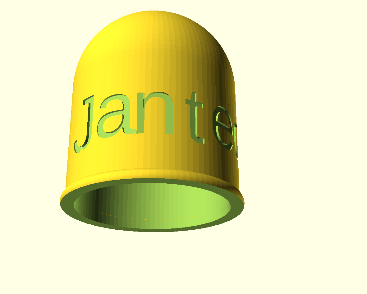
Printed this in red and white ABS on the Voron 2.4 at 260 degrees!
There is also a special version with facets:
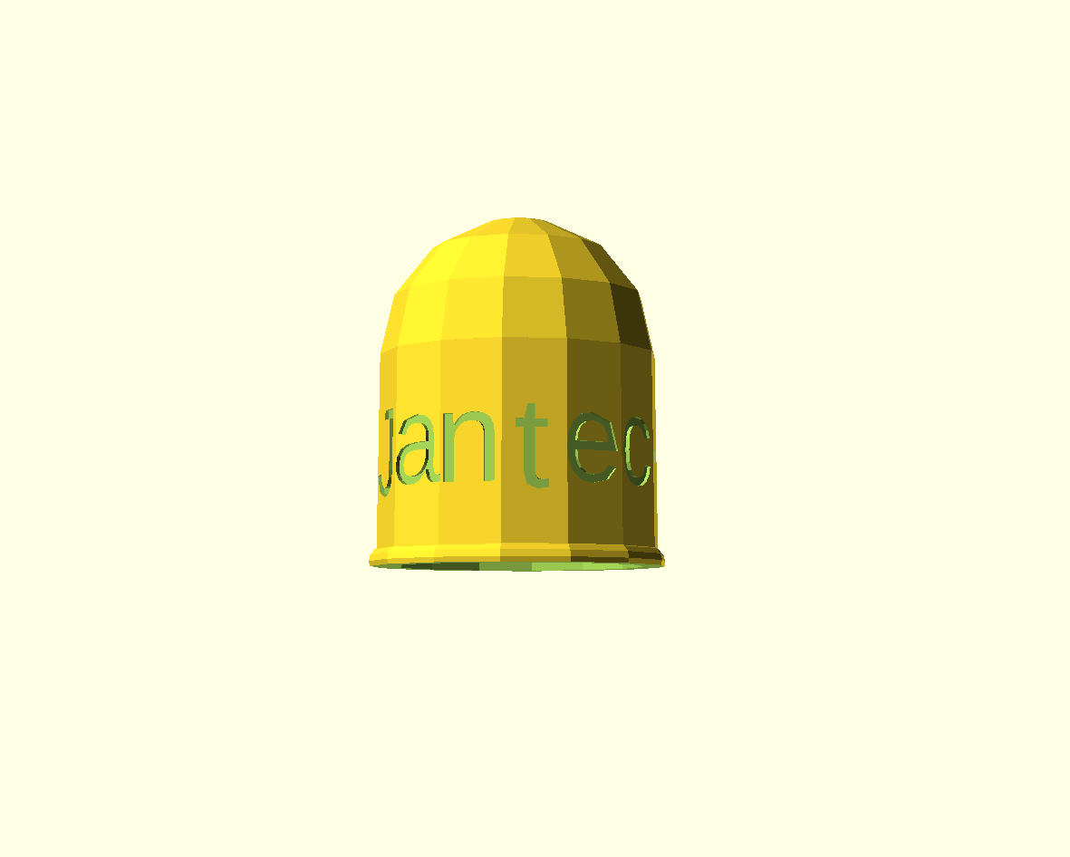 Tow bar ball cover 2-23 05 11 V1 Reve facet shaped FREE DOWNLOAD
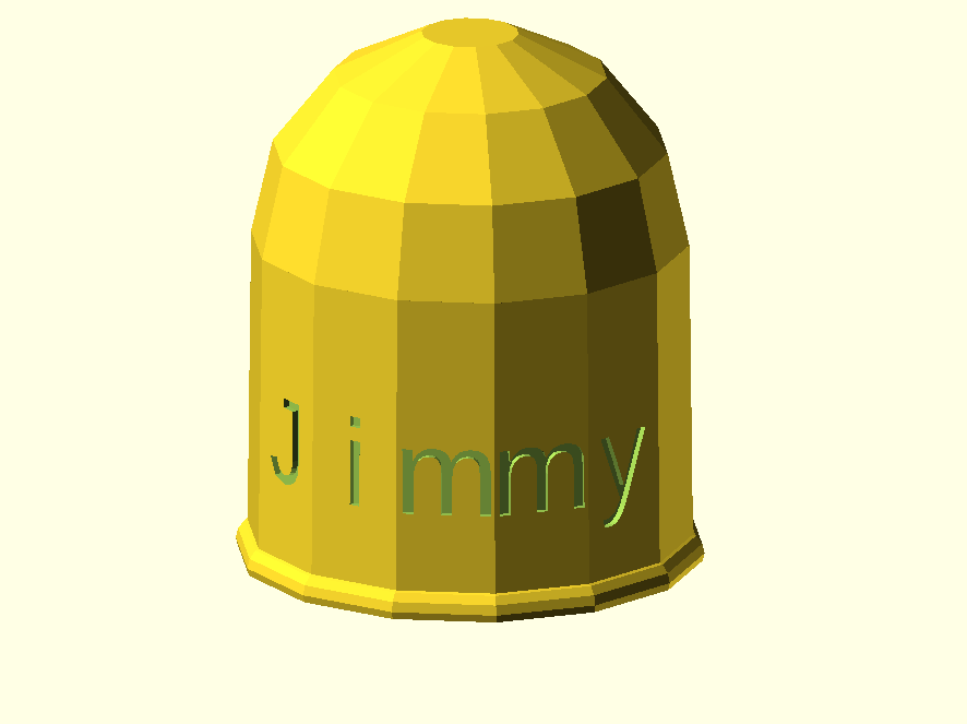
Tow bar ball cover Jimmy 2023 07 04 V1.1 facets
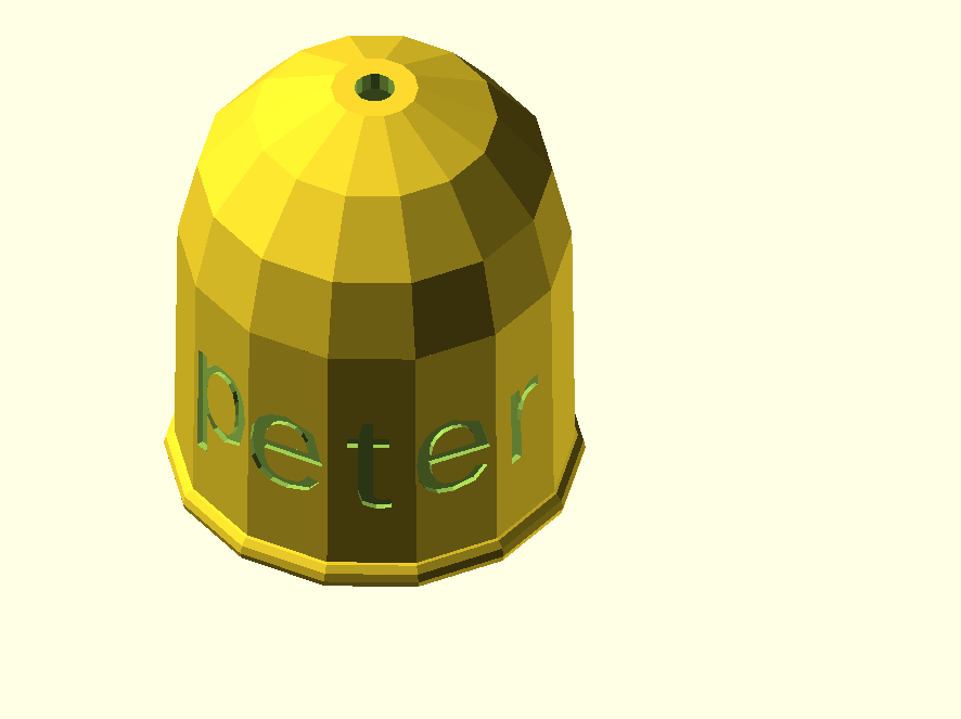
Tow bar ball peter cover 2023-16 06 12 V1 Facet_main FINAL size
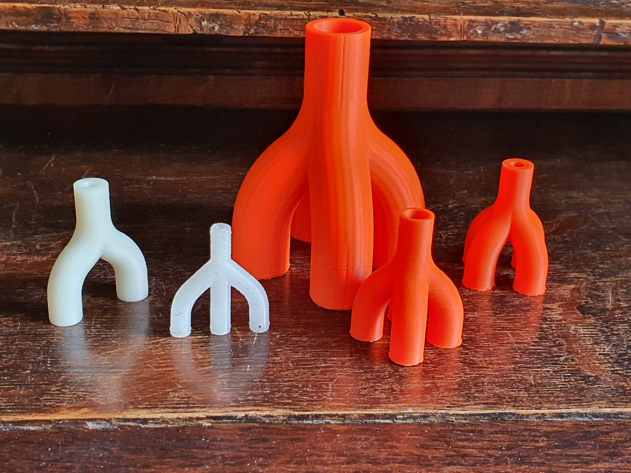
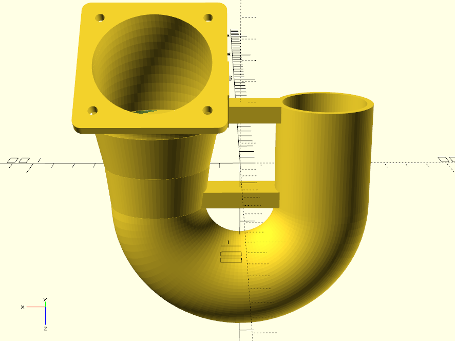
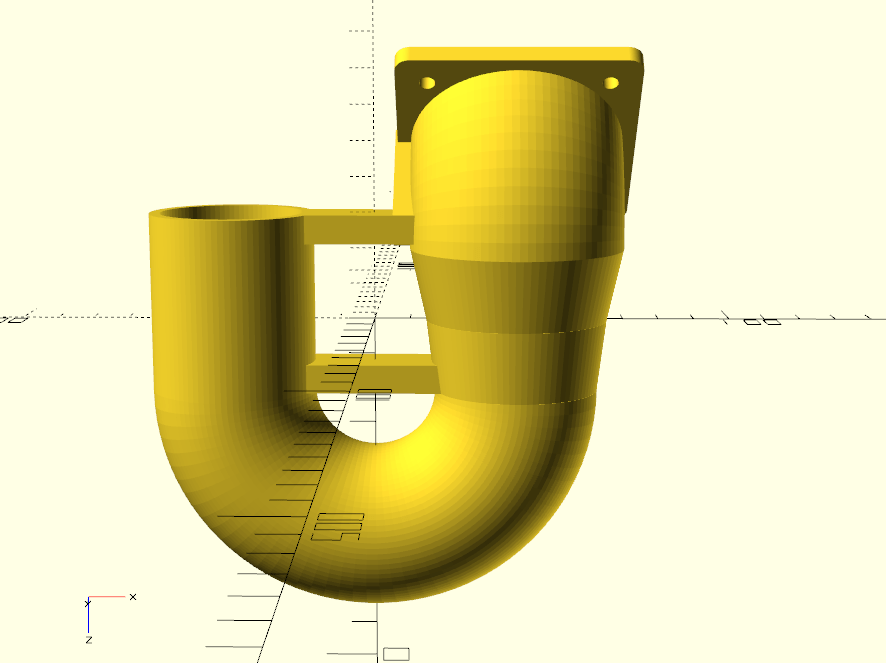
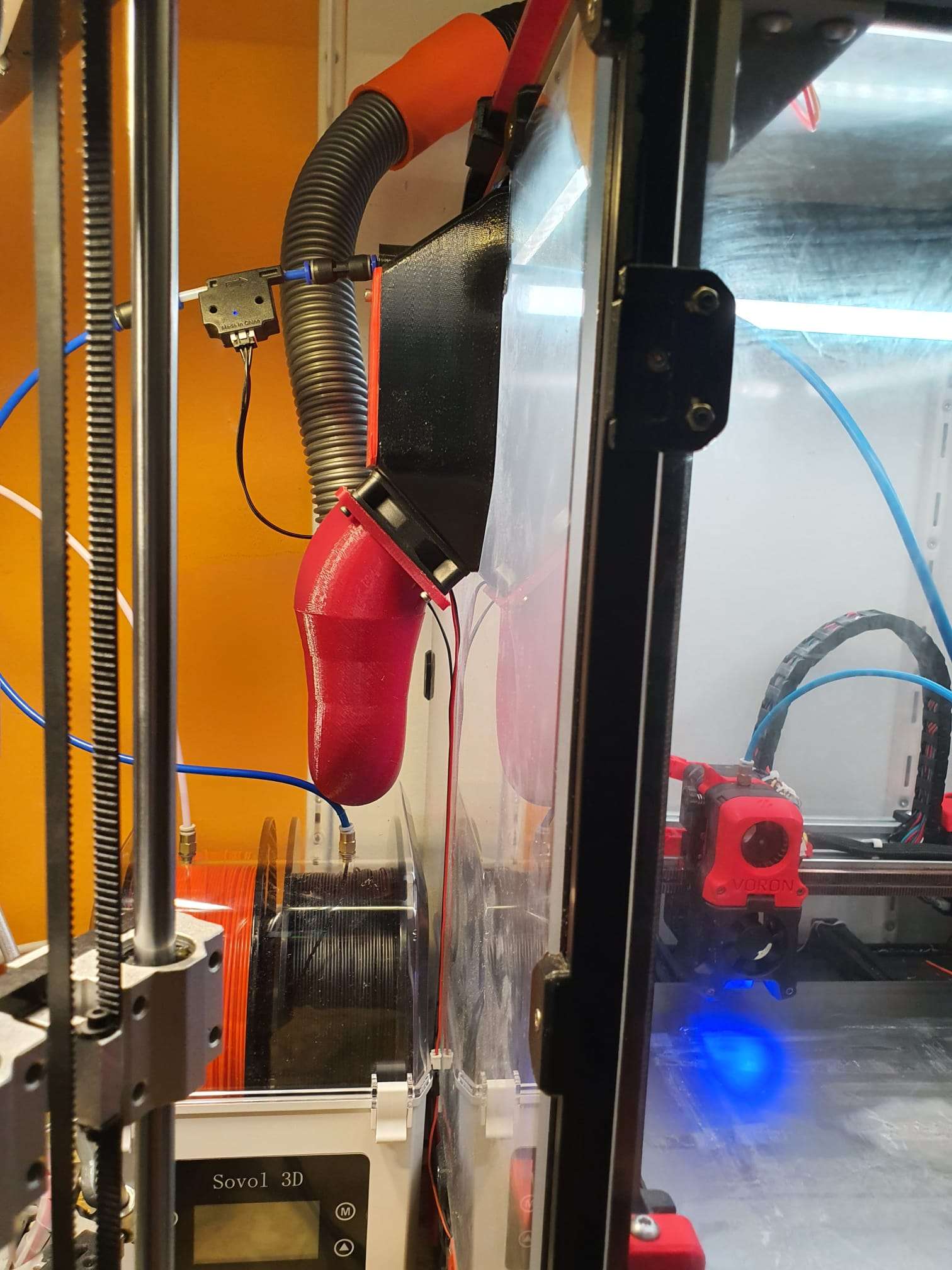
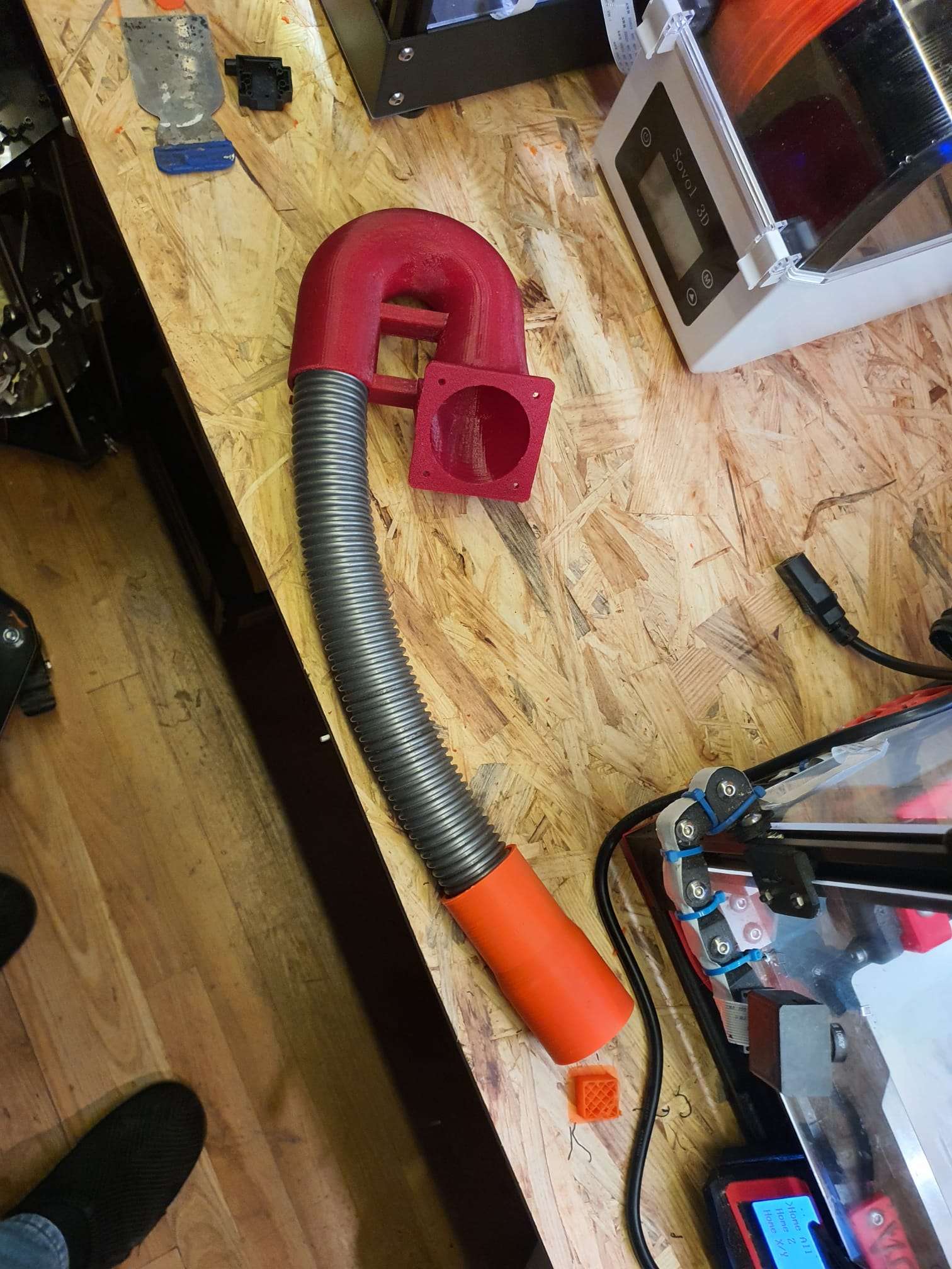
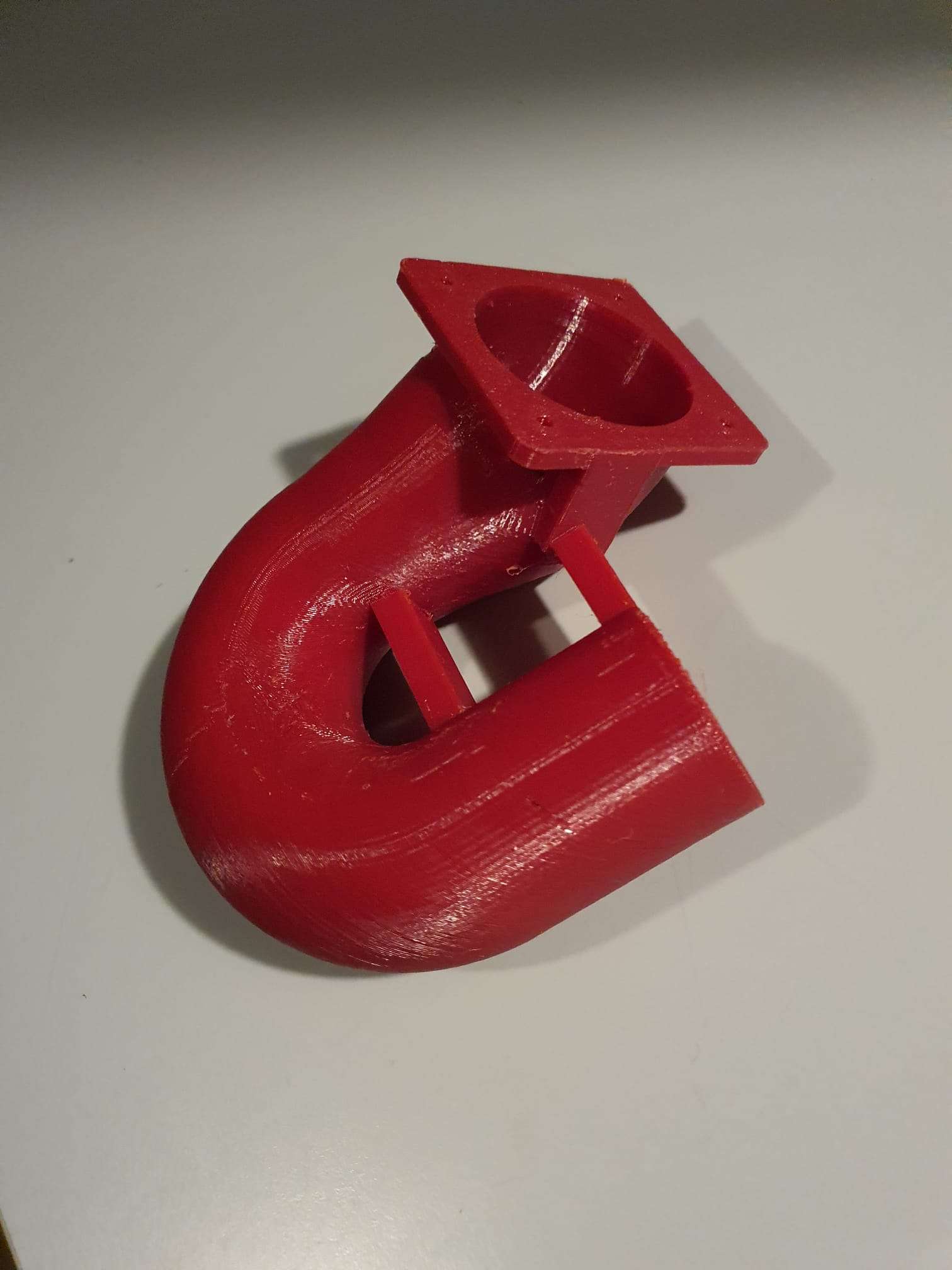
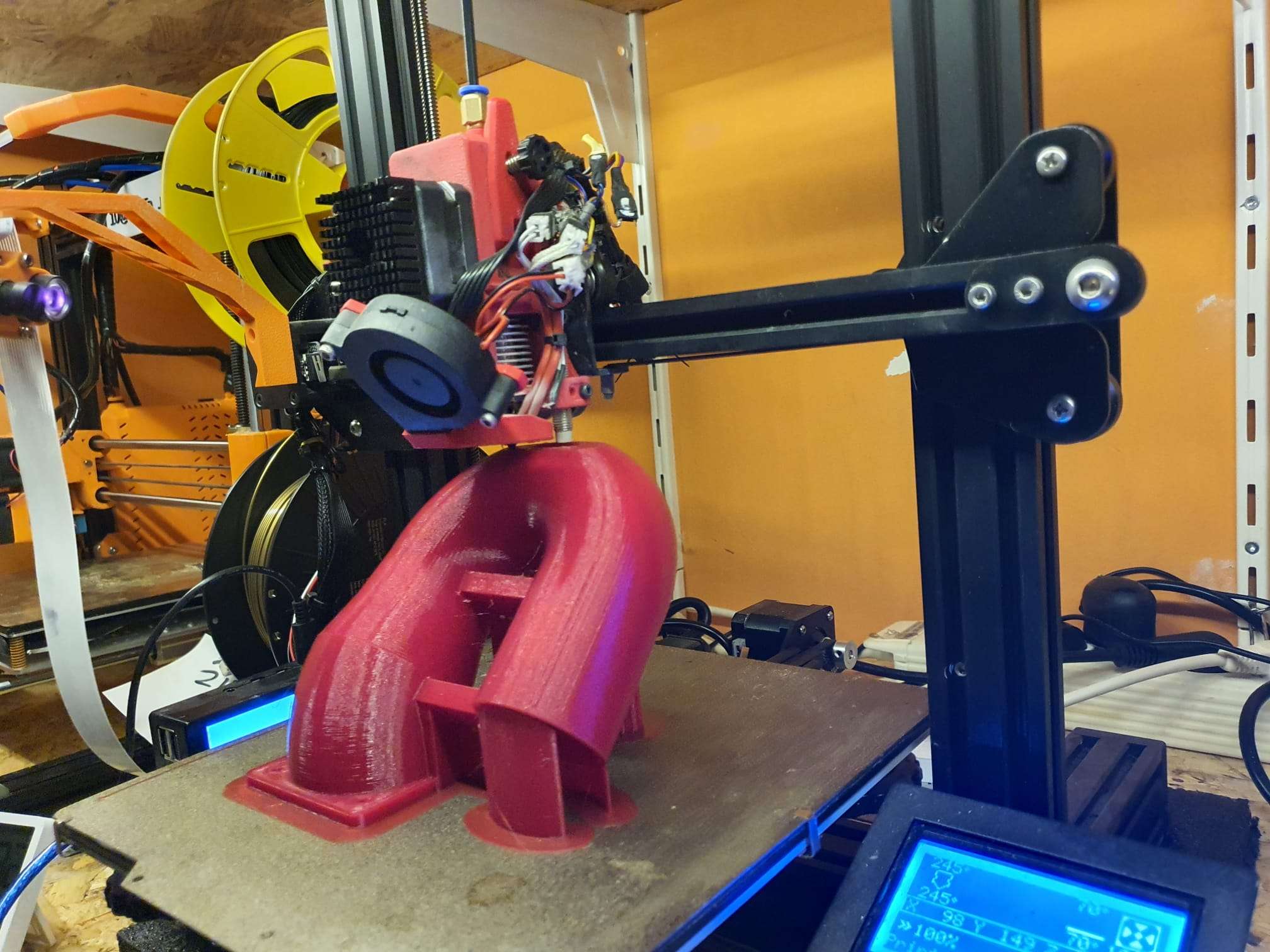
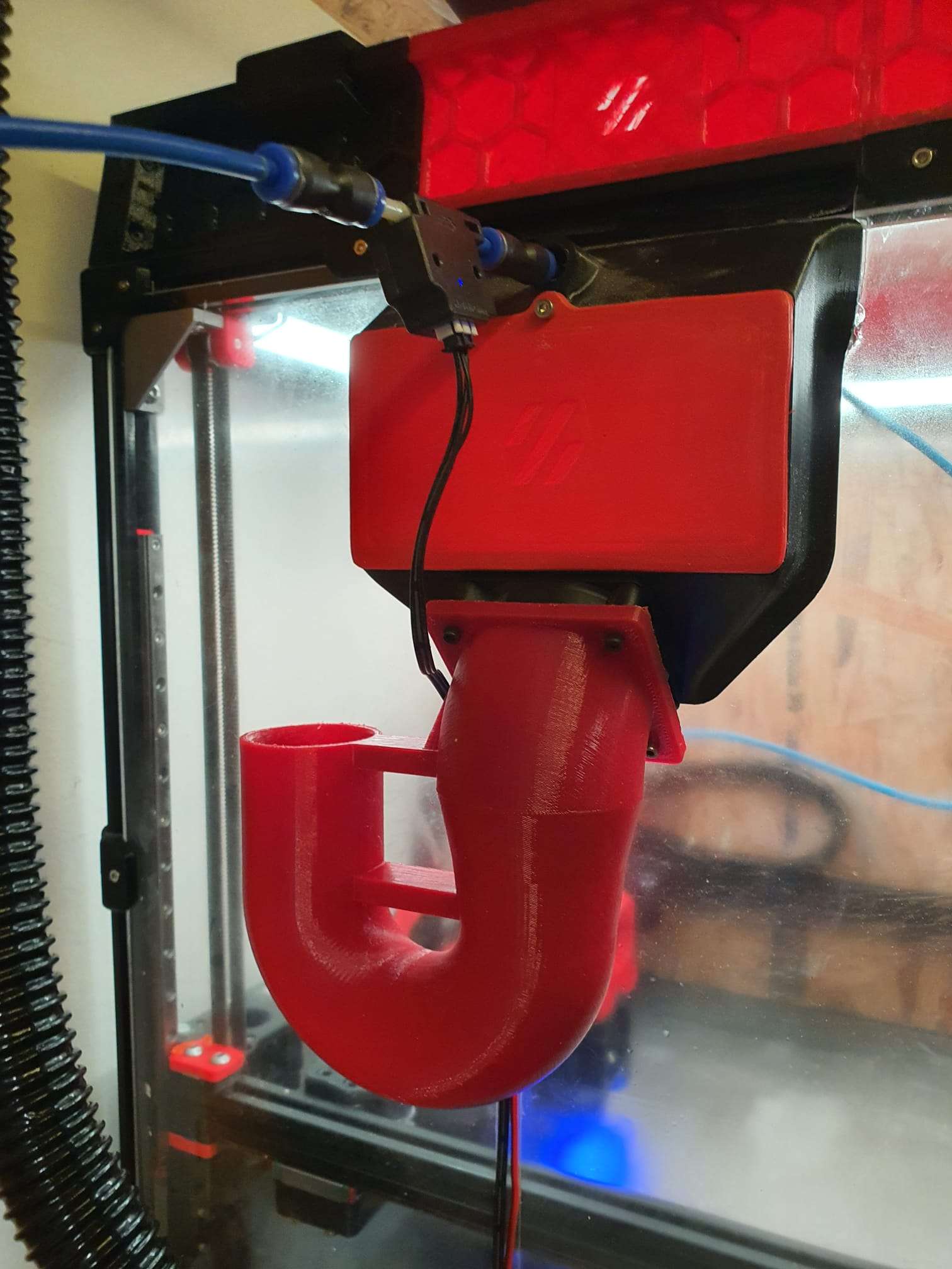
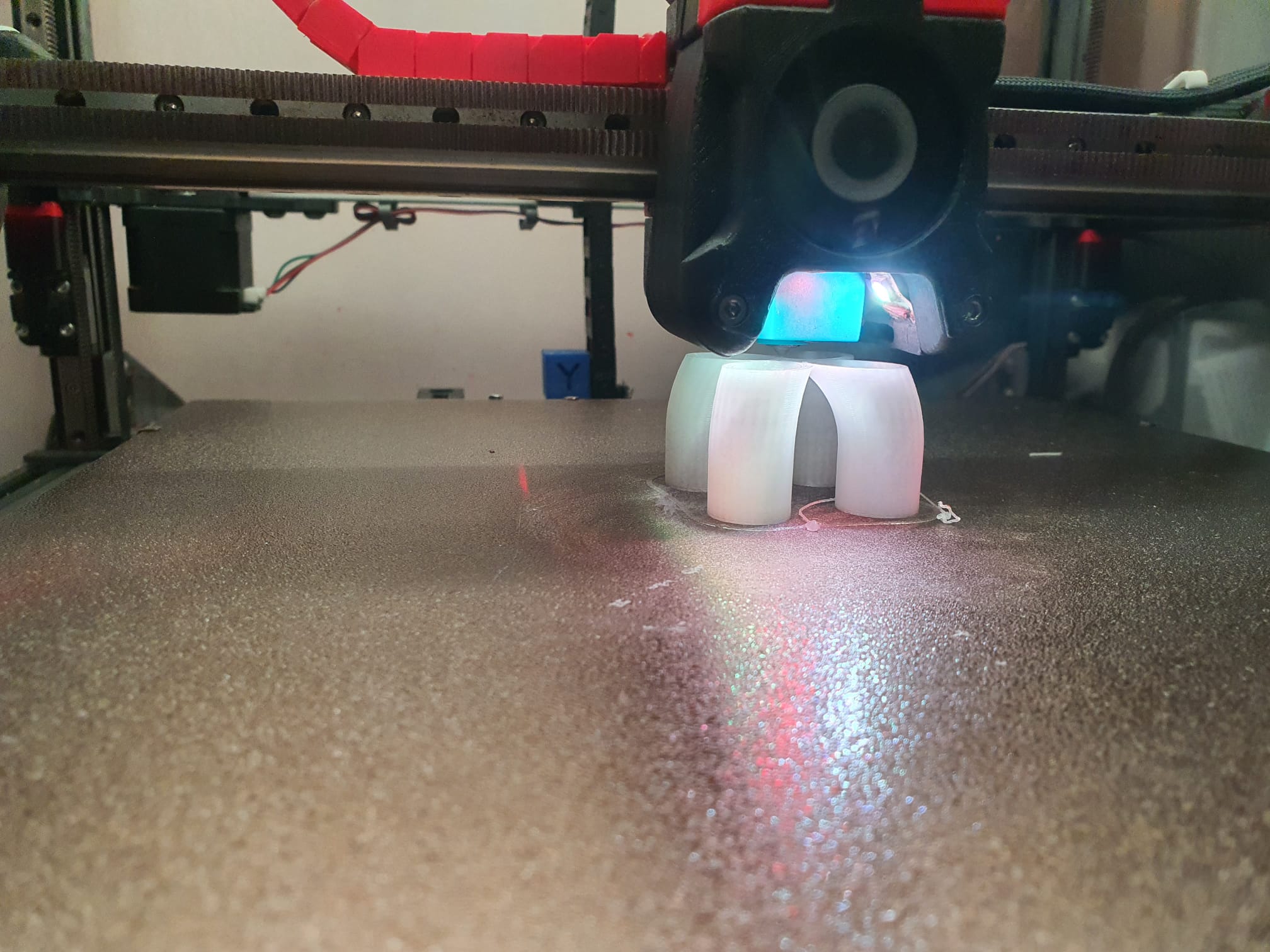
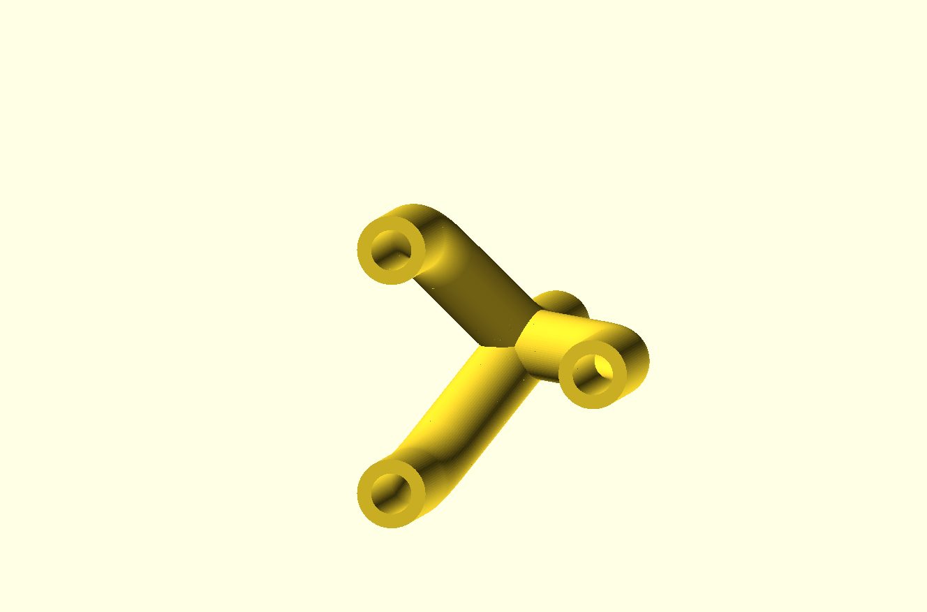
OPEN curvedPipe for pipeconnector 4 into 1 FLAT 2023 05 01 V4 dev a.SCAD
OPEN curvedPipe for pipeconnector 4 into 1 FLAT 2023 05 01 V4 dev a.STL
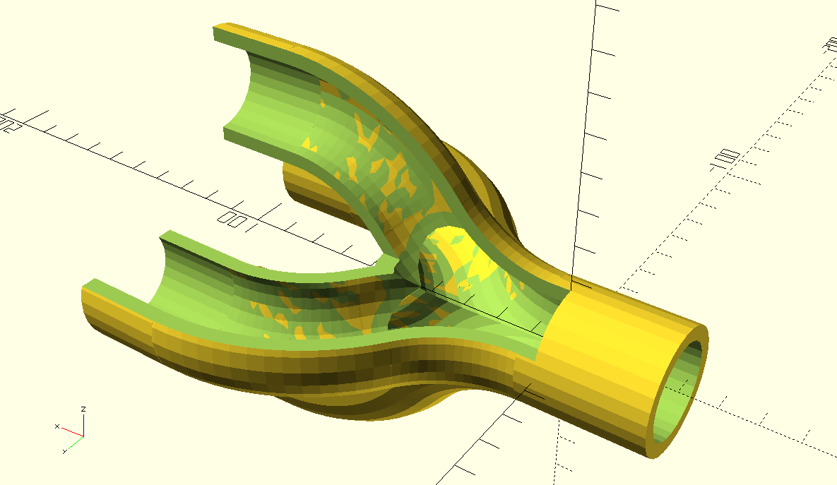
Inside view of the hollow pipes AND the cutouts, which required some setting changes of the Openscad program, w.r.t. higher CSG limits
 Video van WhatsApp op 2023-05-02 om 23.08.14
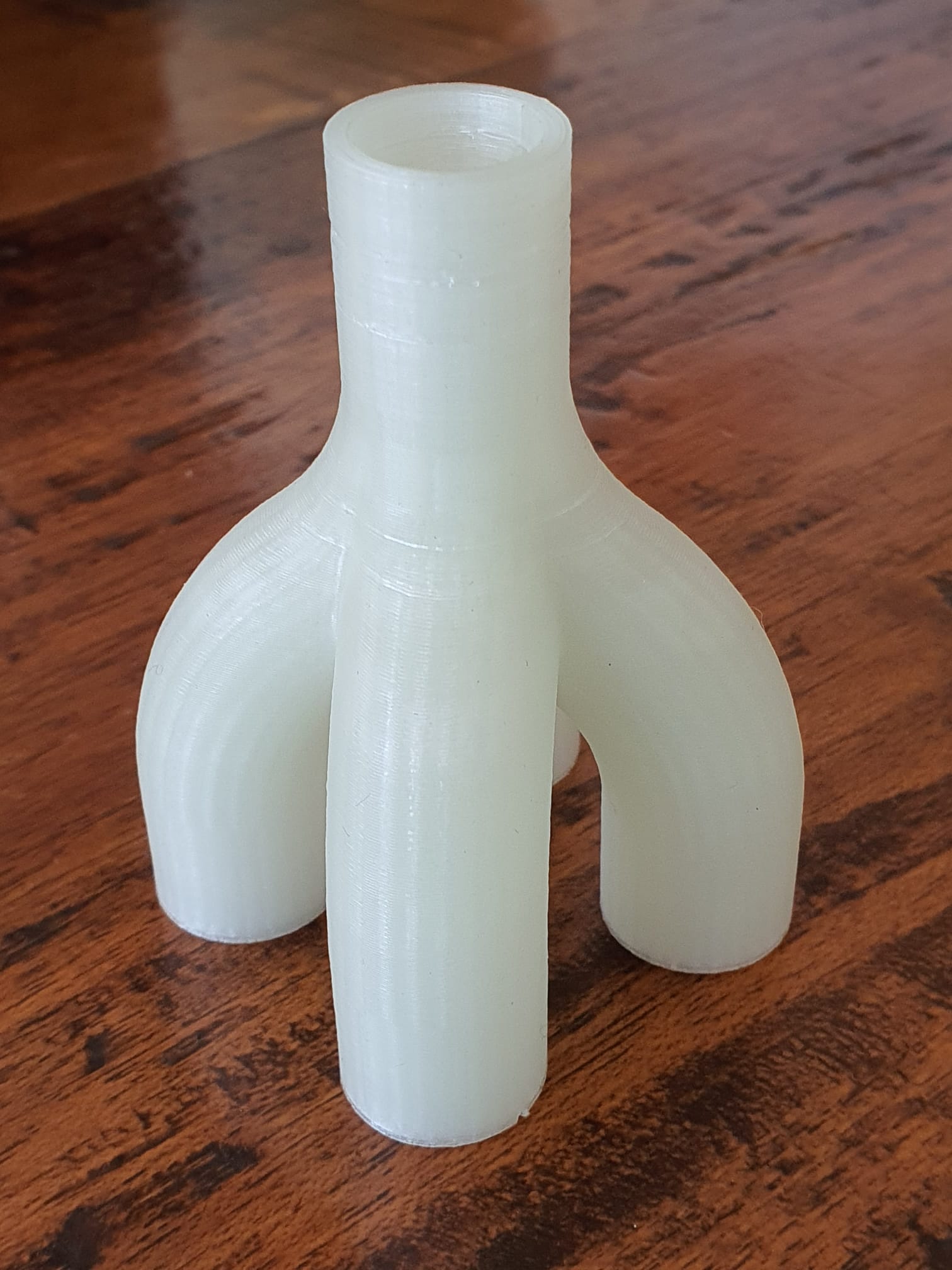
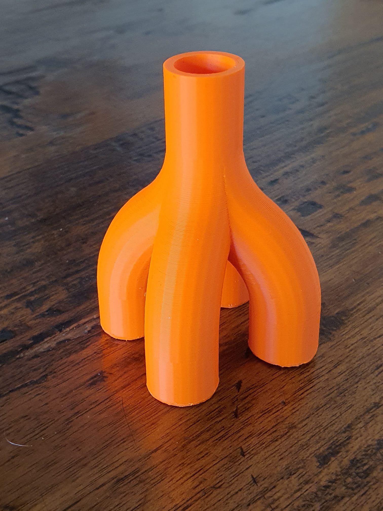
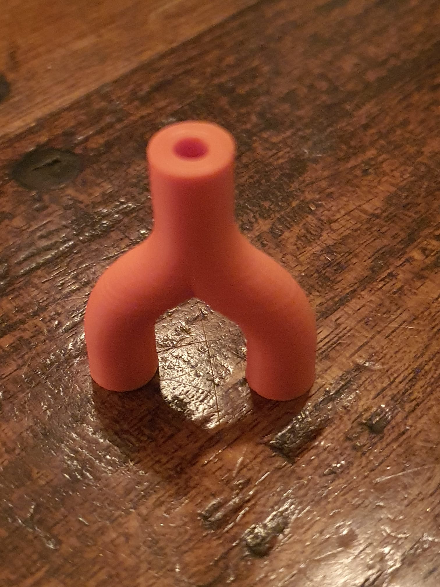
Pipeconnector 2 into 1 all tight_hollow 2023 05 03 V4 dev b STL download
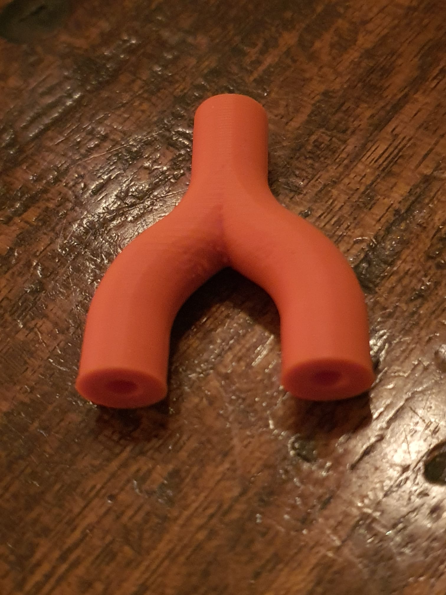
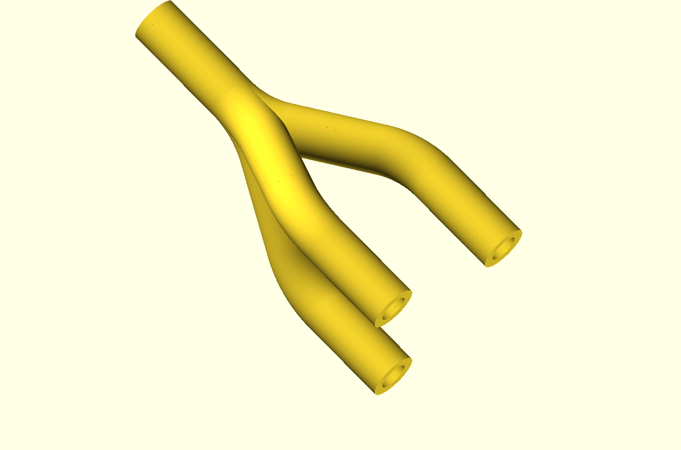
Pipeconnector 3 into 1 all hollow 2023 05 26 V5 dev d 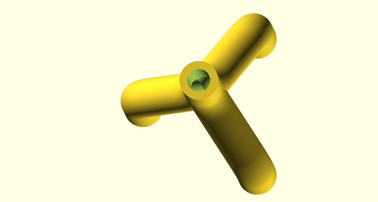
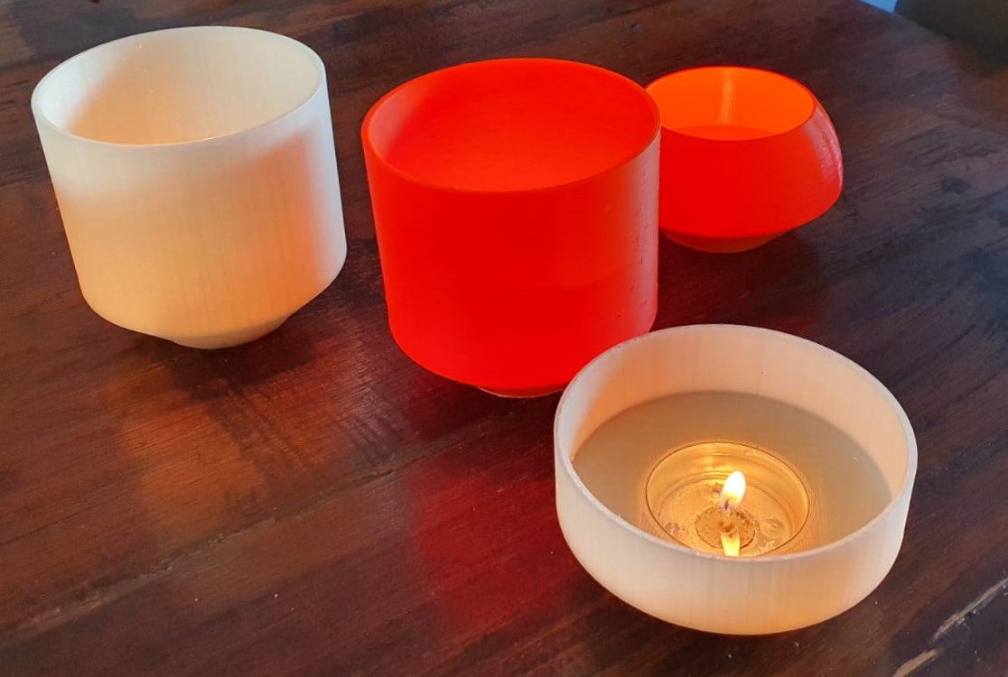
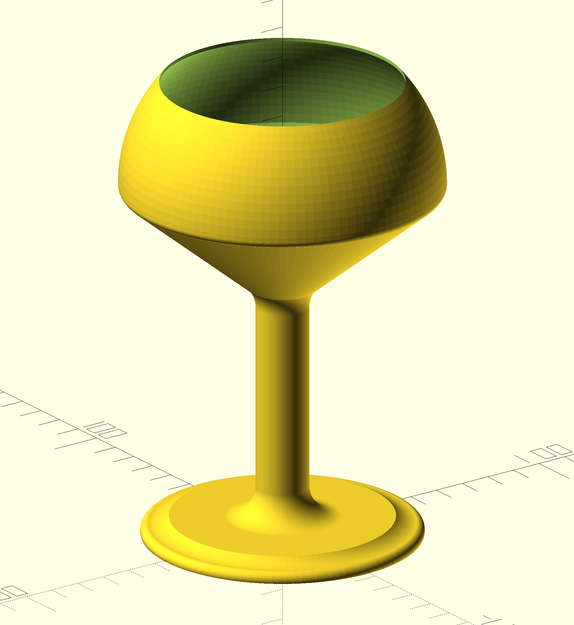
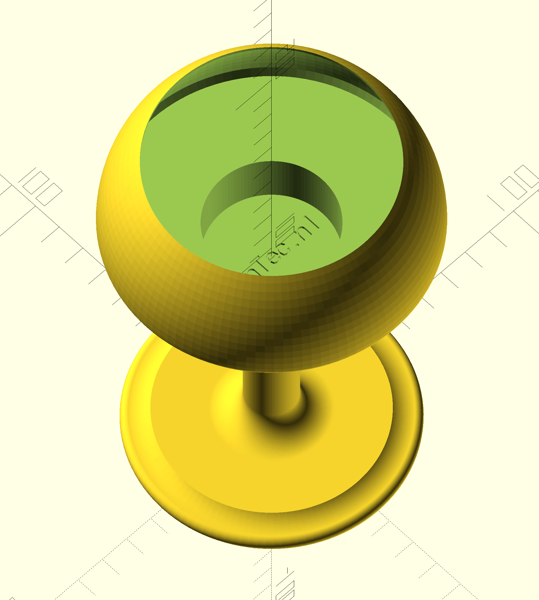
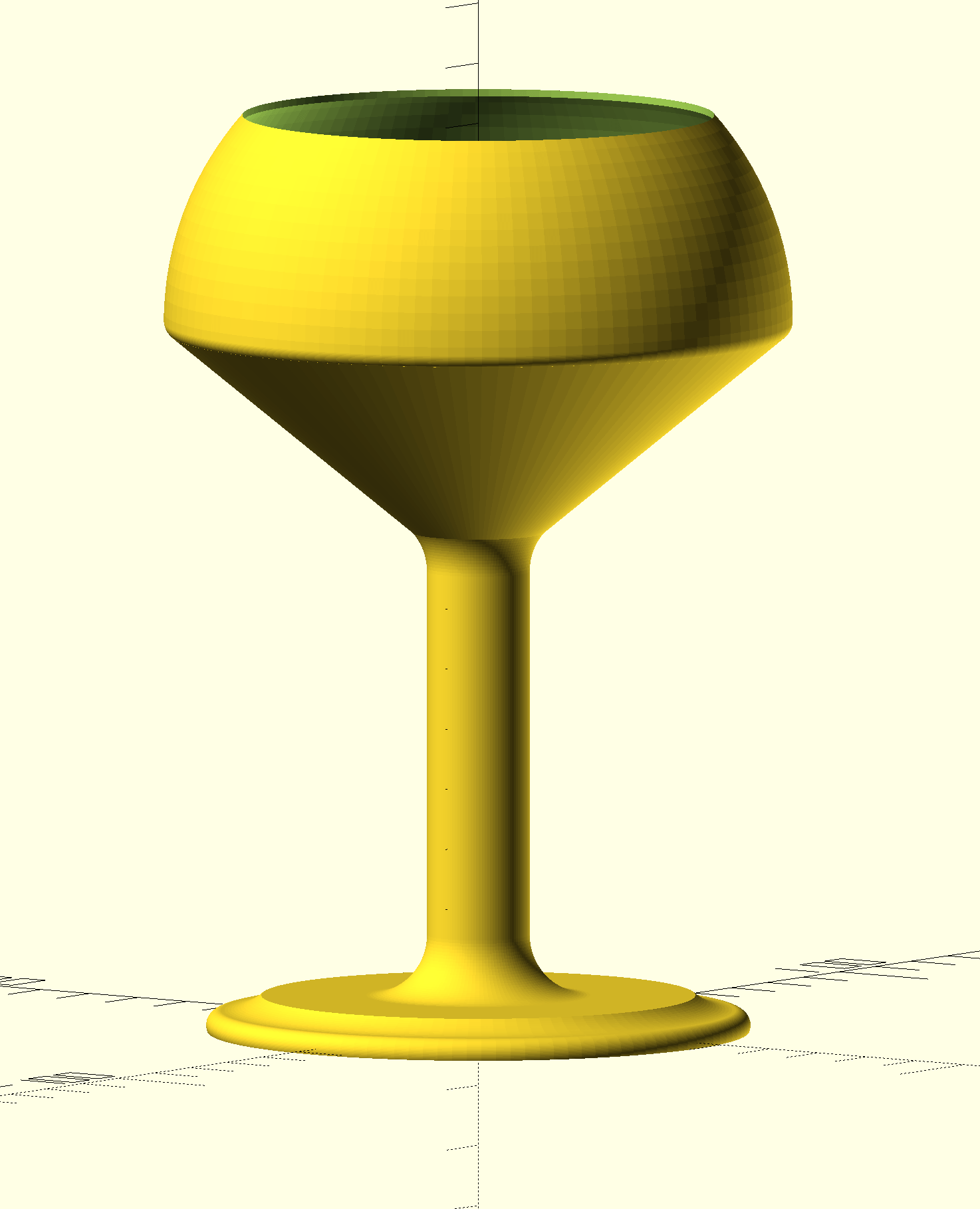
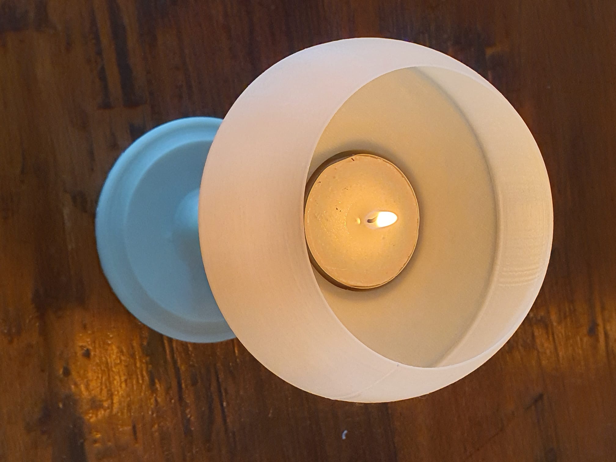
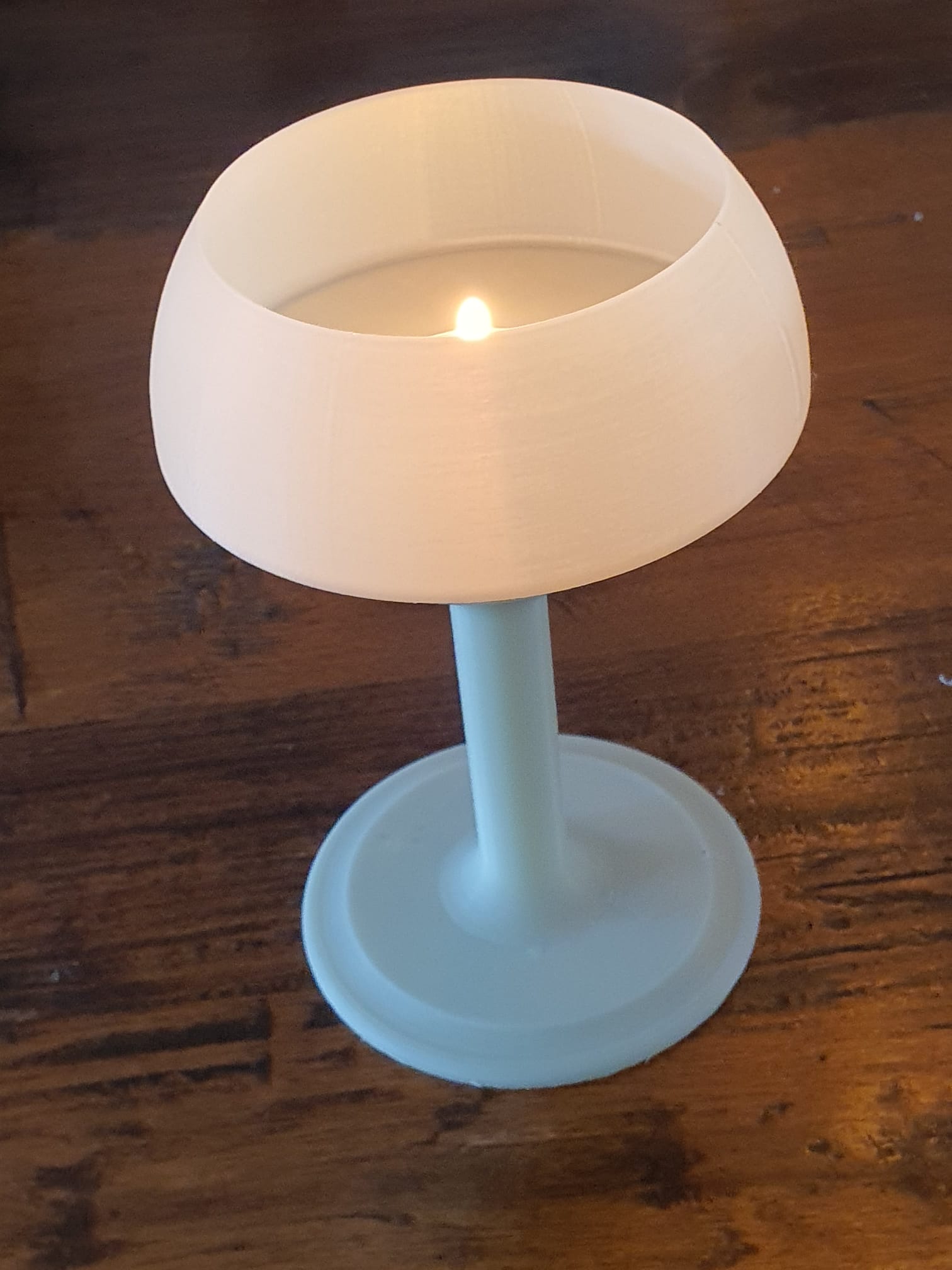
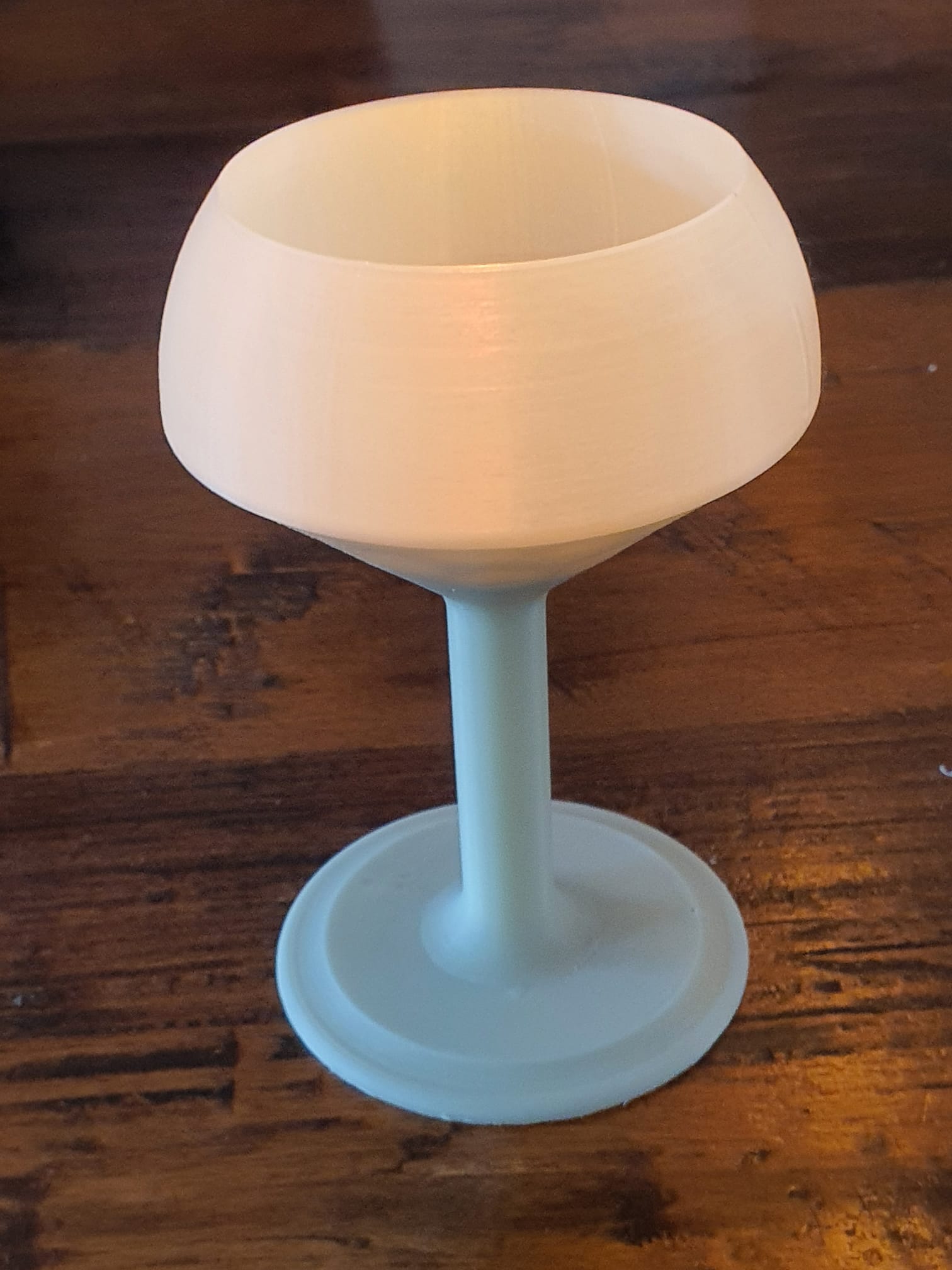
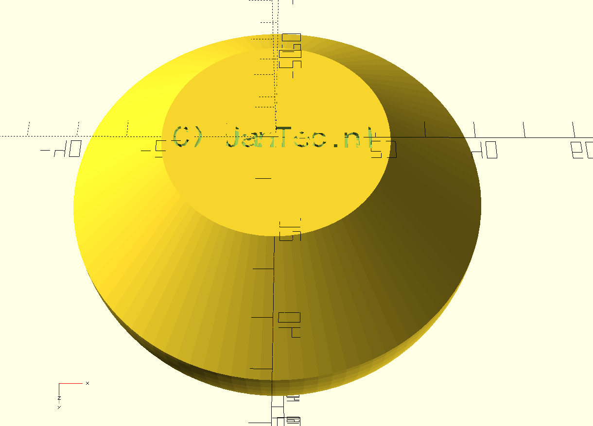
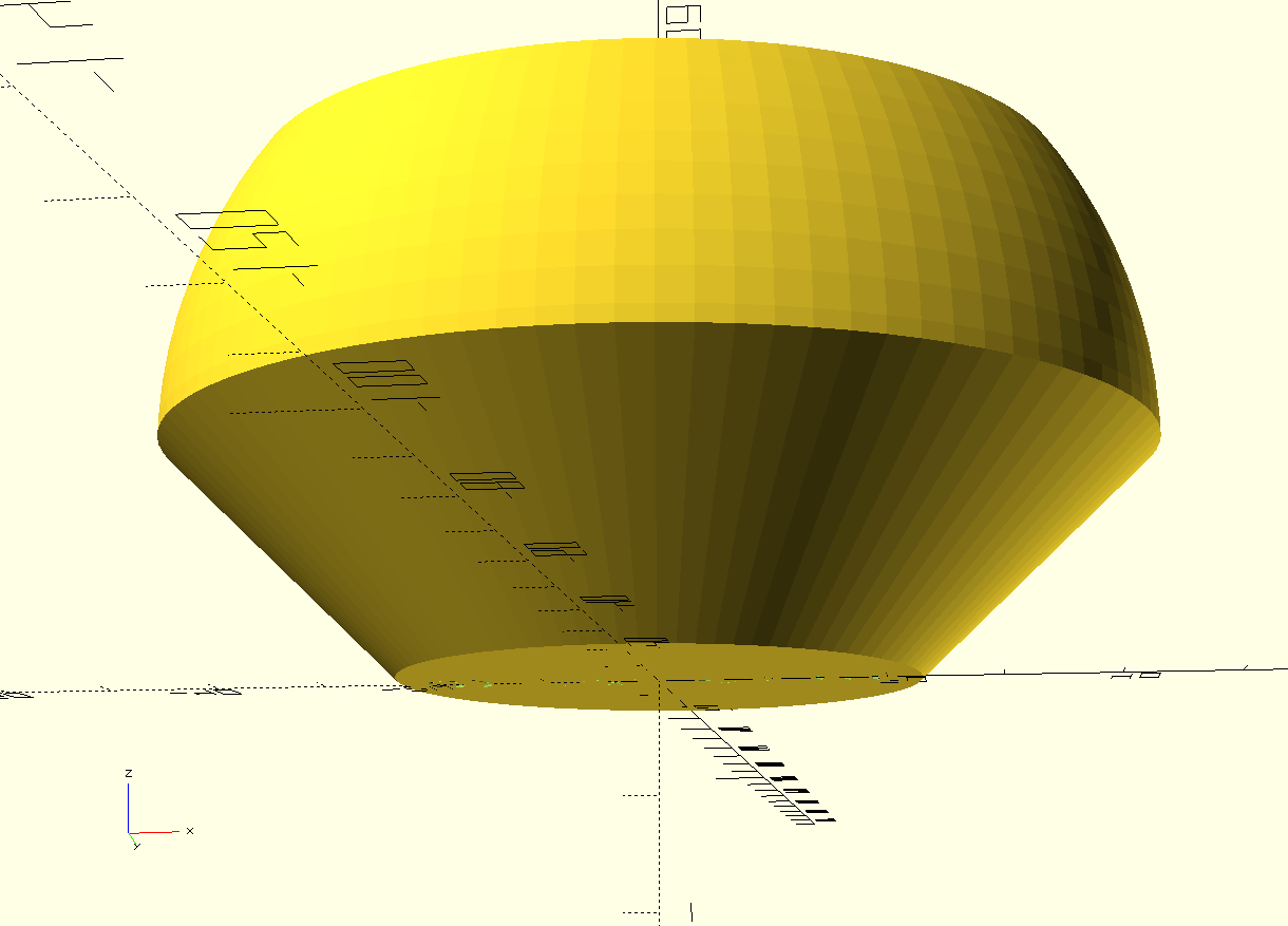
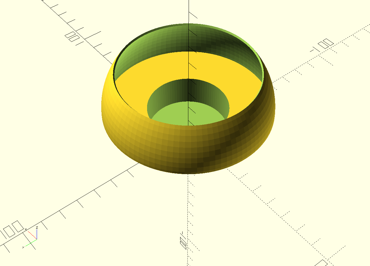
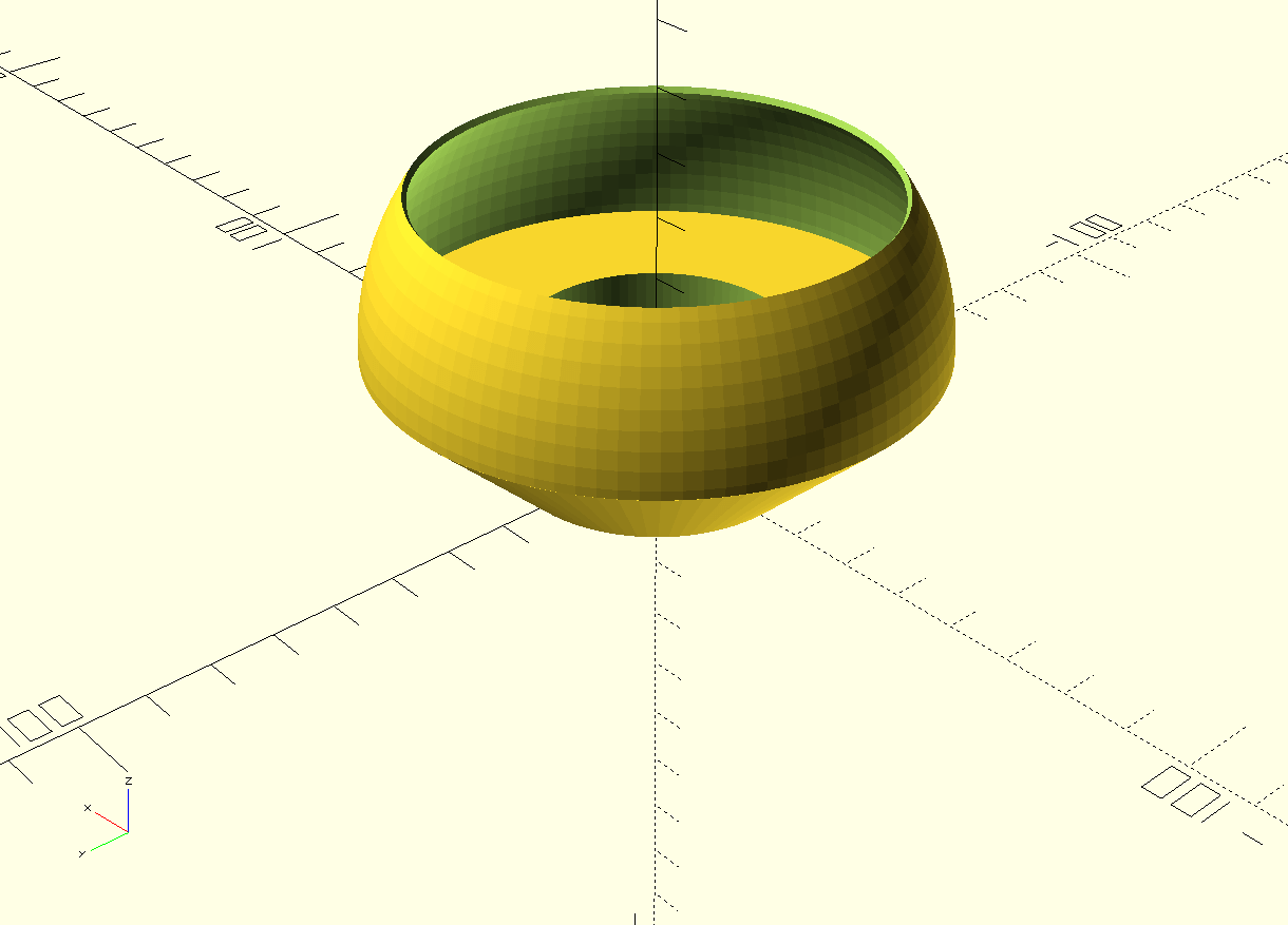
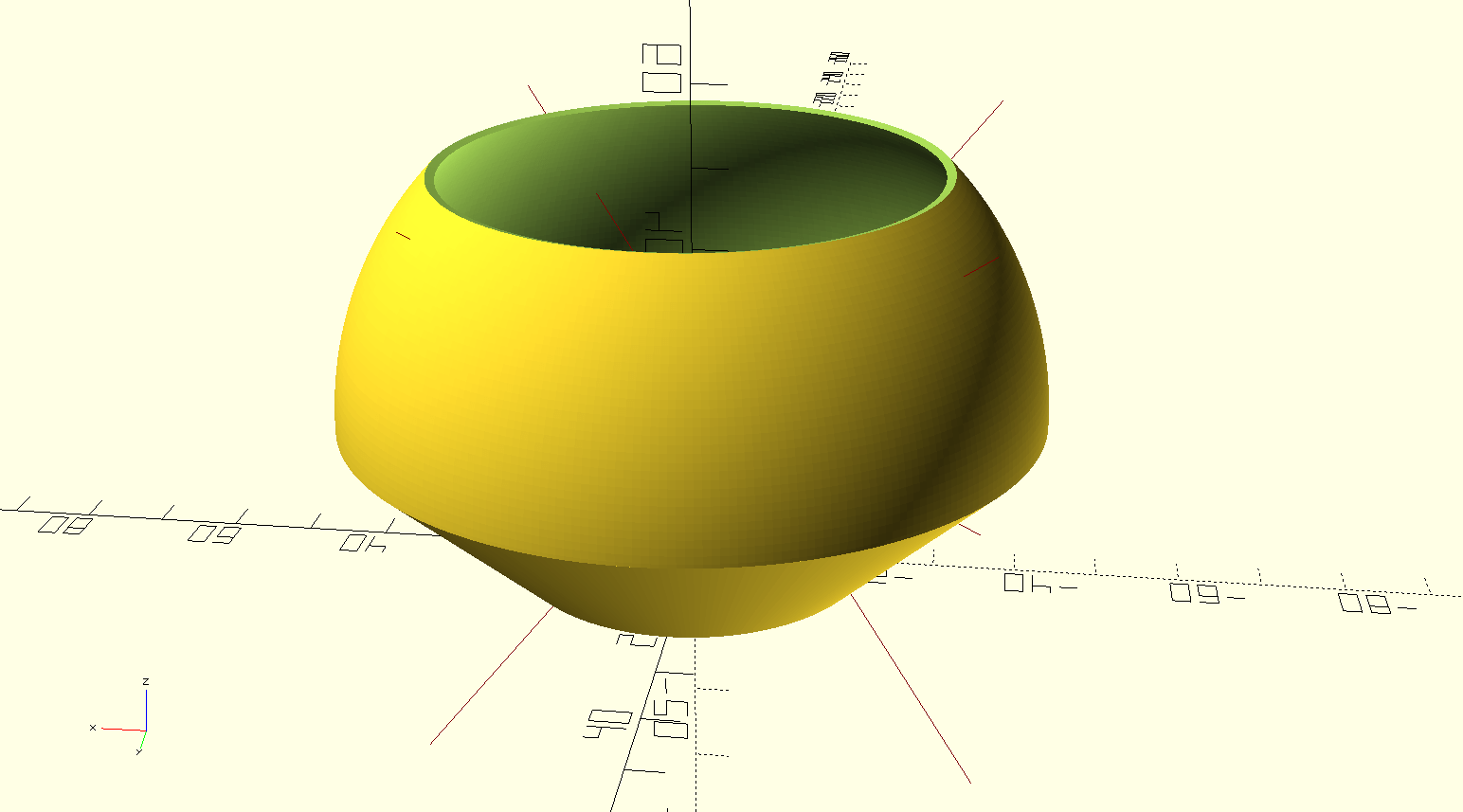
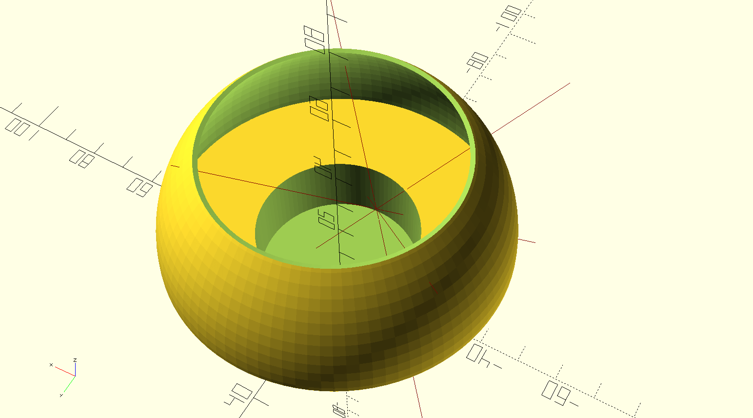
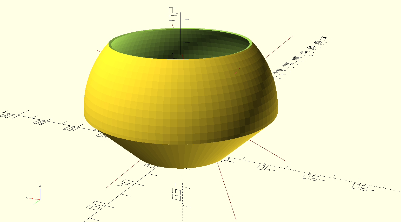
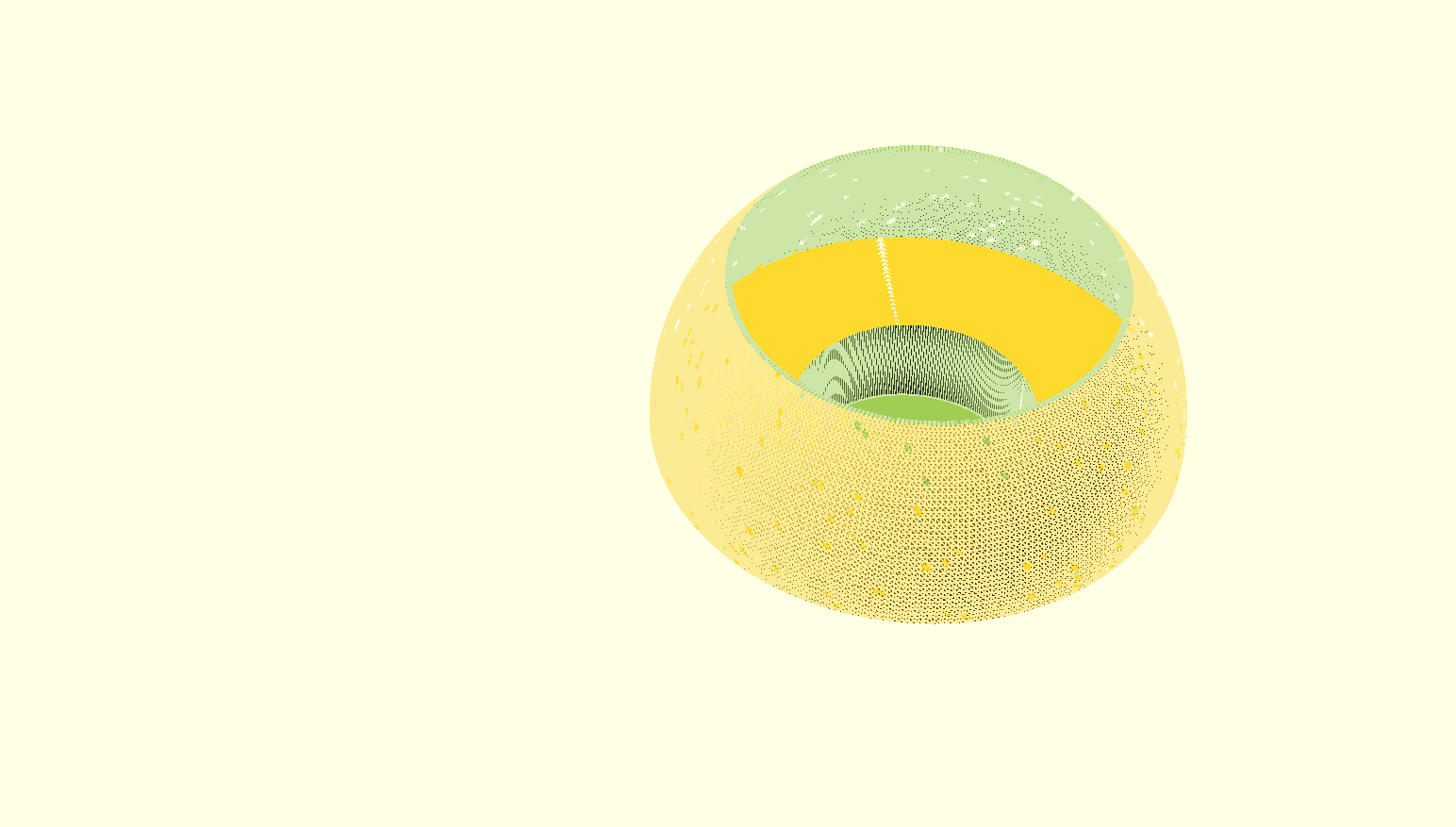
In this version, the tea light holder has a lower open spherical shape so that it can be used with a regular wax tea light.
Further down are the 4 versions of the straight flared tea light holder that are also well suited for use with a tea light.
Of course, an electric tea light is also very suitable for use with these designs.
[ NB: A design for a holder for an electric tea light with a higher inward-facing rim is in the other article. That version is not suitable for a tea light with a flame, because a flame can distort the higher, more inward edge.]
Print these STL files on a suitable 3d-printer with heat-resistant, fairly transparant filament for best effect!
Tea light chandelear convex and sphere Jantec.nl 2023 04 18 V9 STL DOWNLOAD
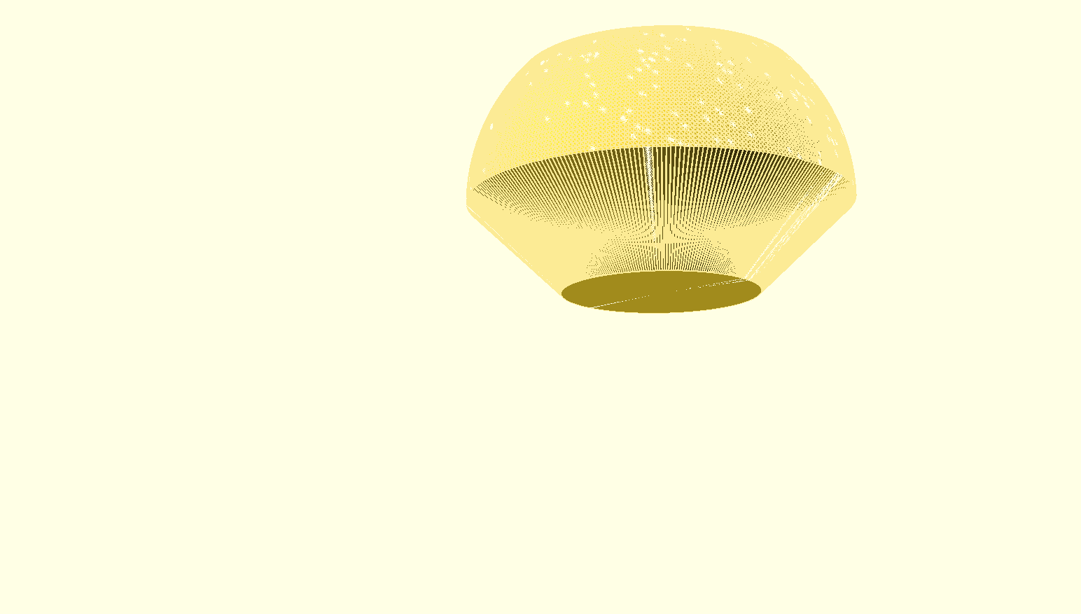
Cylinder extra high
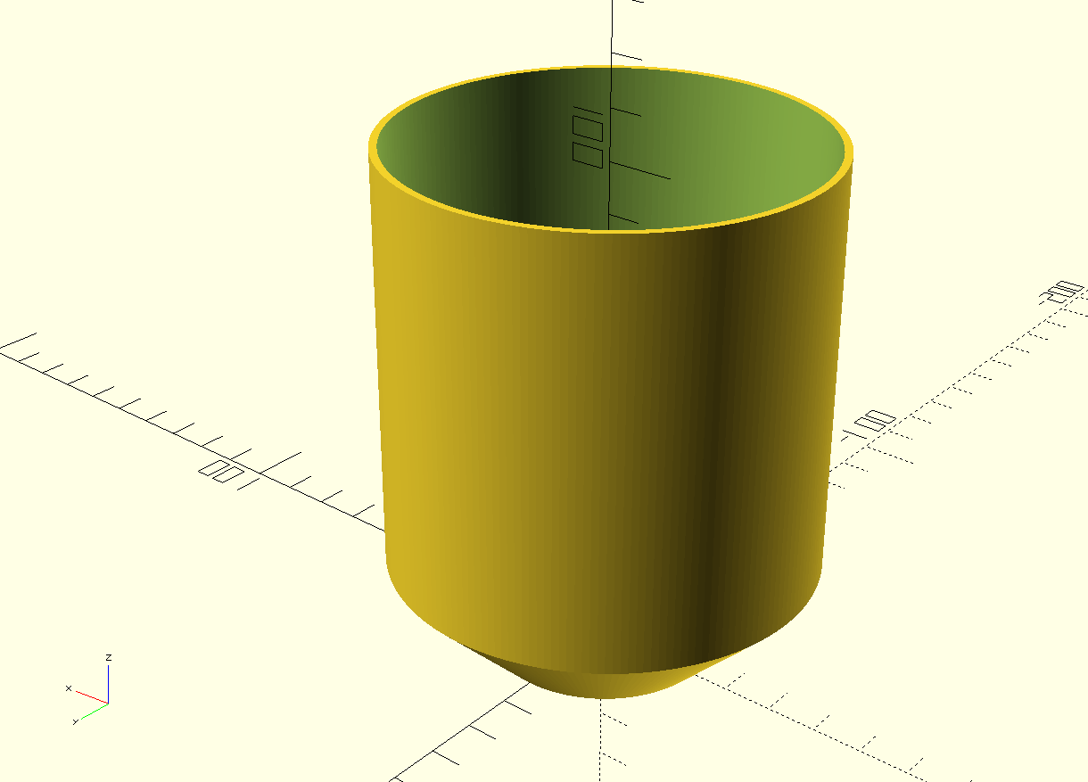 Tea light chandelear straight very high size Jantec.nl 2023 04 20 V2b STL DOWNLOAD
High
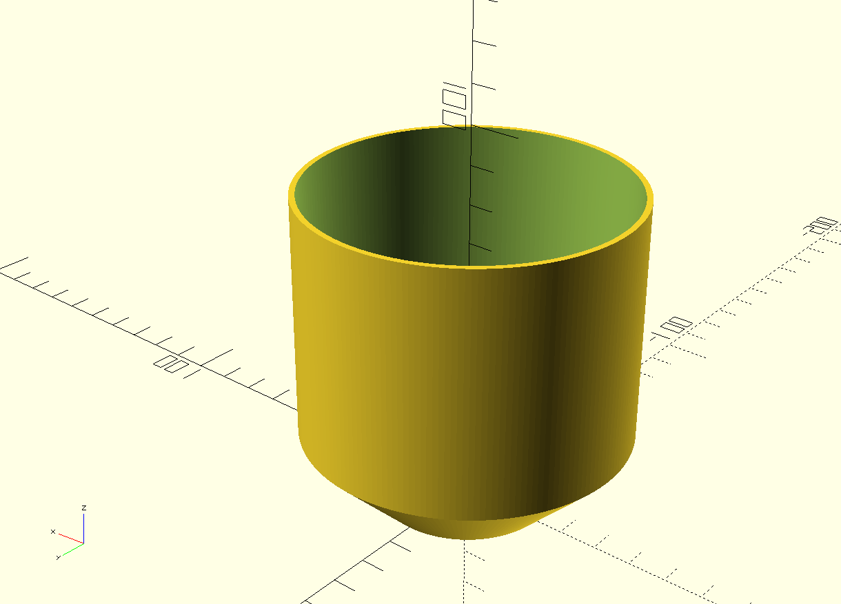 Tea light chandelear straight high size Jantec.nl 2023 04 20 V2b STL DOWNLOAD
Medium
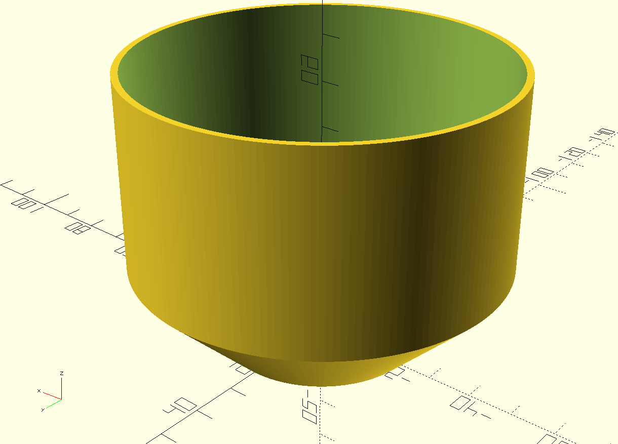 Tea light chandelear straight medium size Jantec.nl 2023 04 20 V2b STL DOWNLOAD
Low
Tea light chandelear straight low size Jantec.nl 2023 04 20 V2b STL DOWNLOAD
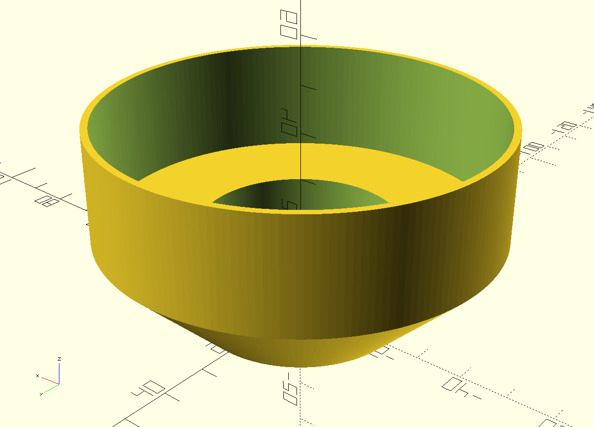
This holder for an electric tea light with a top higher inward edge is not suitable for a tea light with a flame because a flame can distort the higher, more inward edge and may cause a fire hazard.
STL designs better suited for original tea lights with a flame are in the article: 5 free printable STL files for a table lamp with tea light
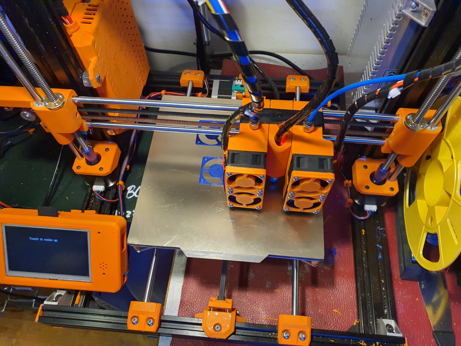
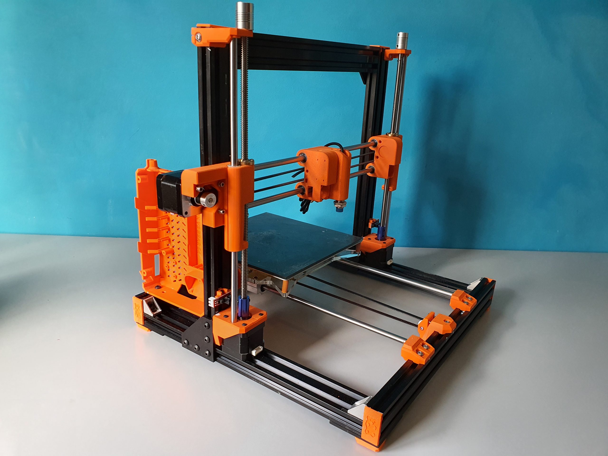
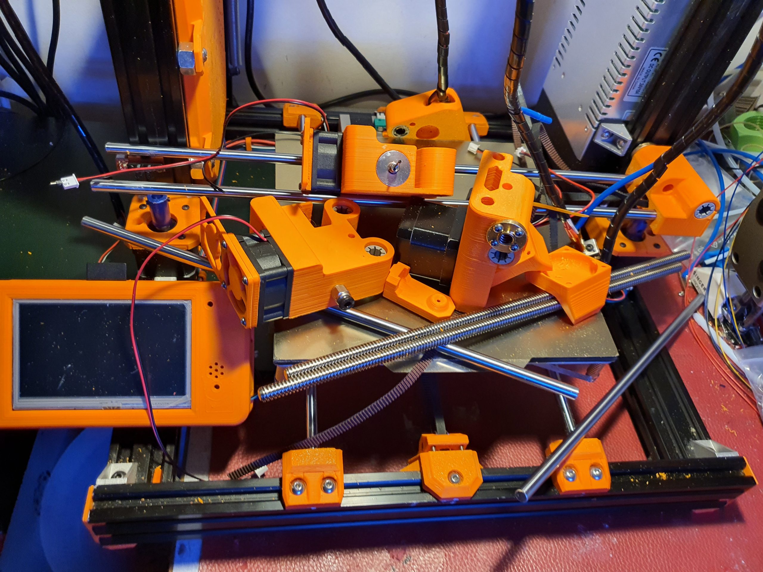
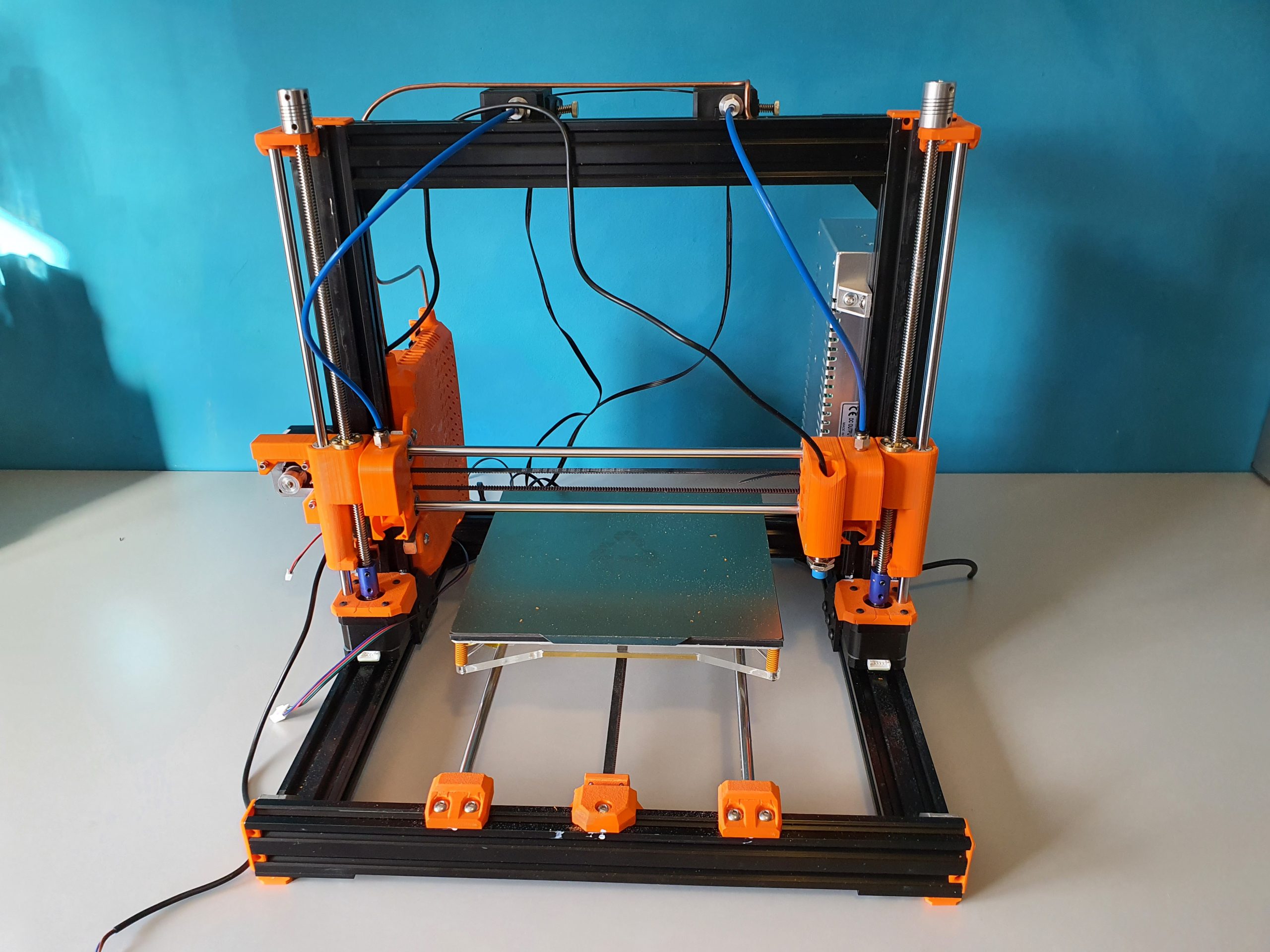
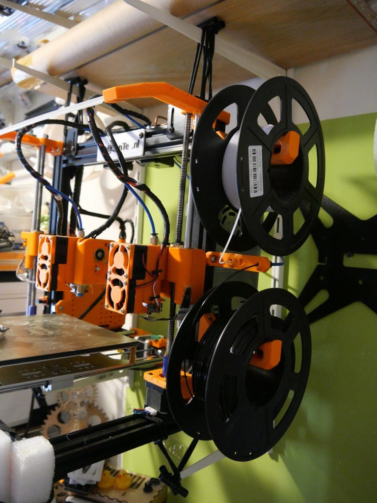
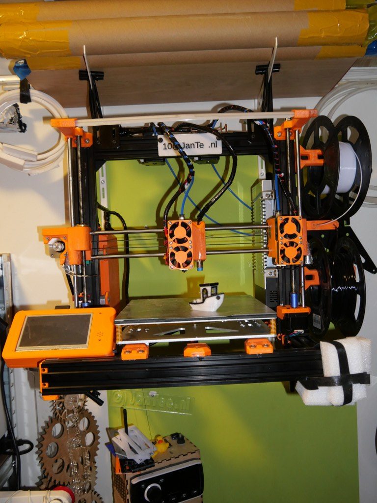
My dual carriage I3-bear based 3d printer is working very well.
On this page I share my latest configuration files, my build experiences like the used STL’s , schematics and so on.
Hope you enjoy!
Be aware that the tool settings in config.g are set including relative X, Y, Z values for this build so DO NOT put this in your slicer!
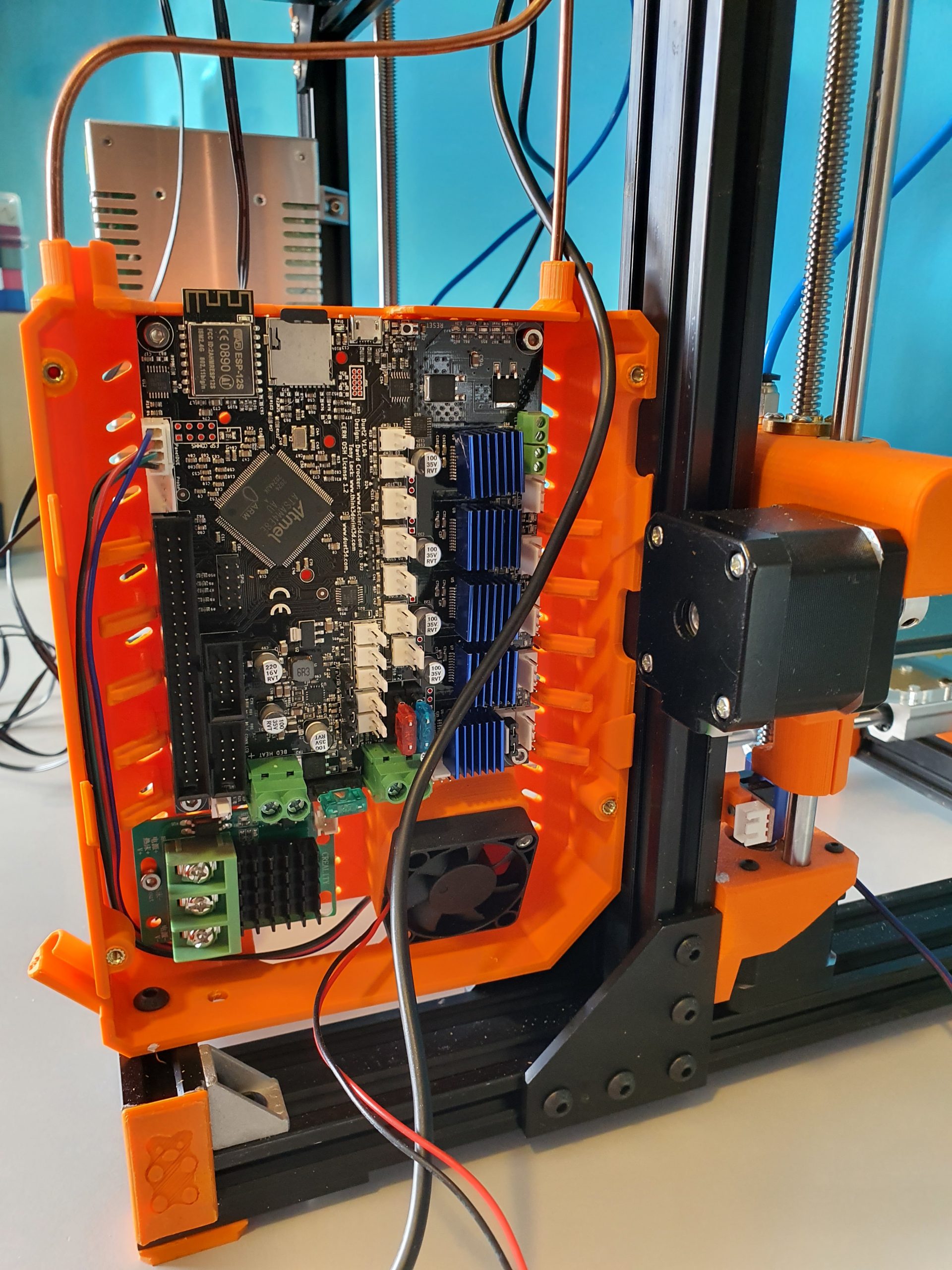
And- you need at least RRF3.3.1 for reprap FW and for DWC.
The sensorless homimg also requires knowledge of config settings and the good news is that the Duet2wifi has this all managed by the reprap firmware. No switches needed or complex jumper settings!
Tip for printing the parts: I used ABS for all parts. Use at least a printer with calibrated XYZ values for your specific filament.
Do a testcube first and apply any needed adjusting to your slicer’s settings like pre-shrinking settings of the endresult and so on.
If you don’t do this, then don’t start this build.
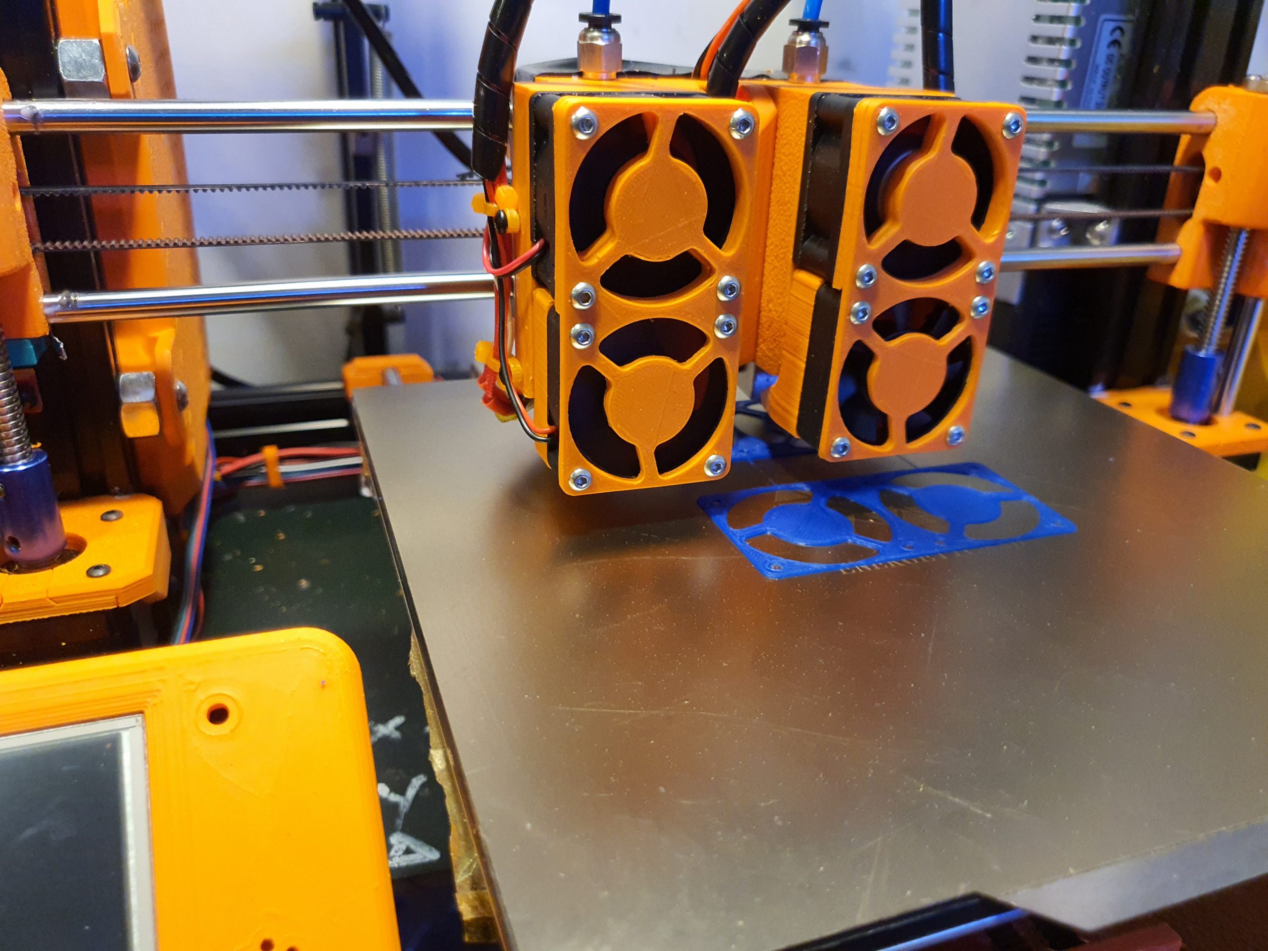
It is a prerequisite to get the magnetic carriage to deliver-and get the carriages from left and right of the X-axis.
Therefore the movement needs to be free of unneccessary friction.
And– if you use sensorless homing any additional friction on any sensorless homed axis might lead to unintended stalls.
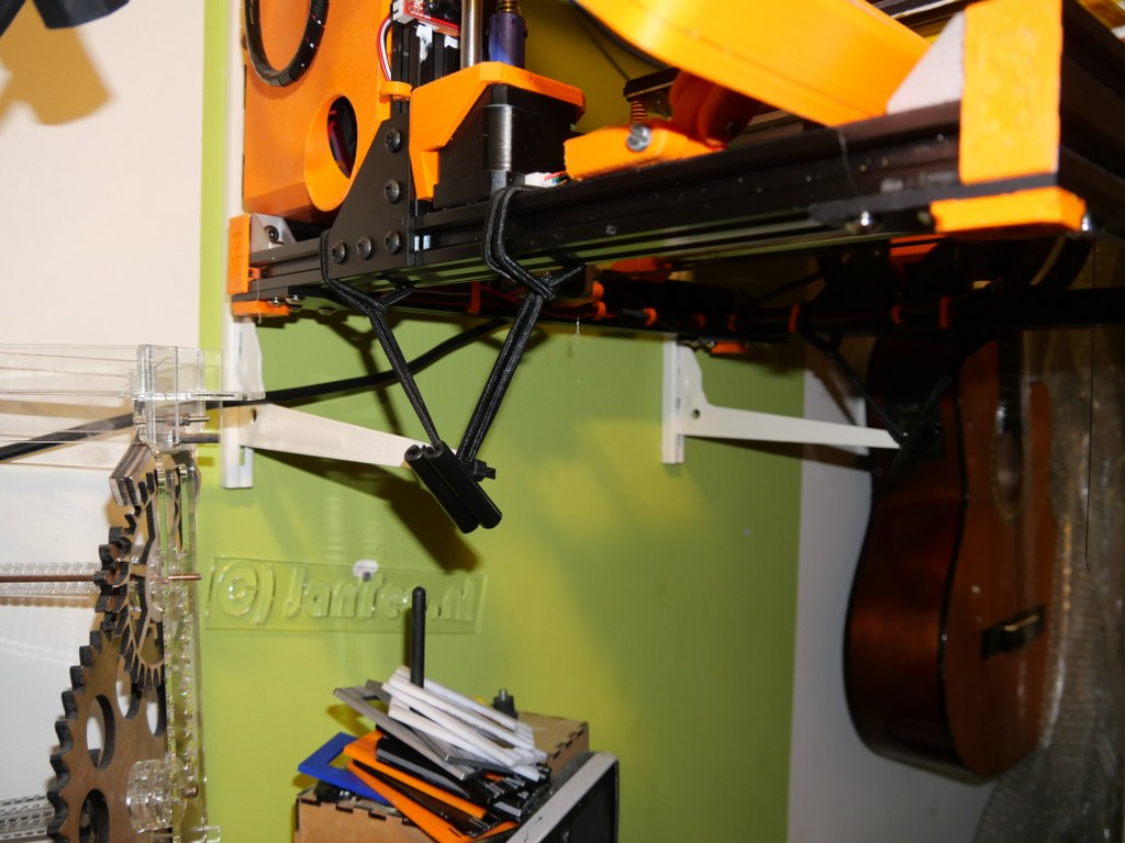
I added a dripstop to the left and right hand sided X-carriages, made of some thin tinned plate.
It is positioned so, that a little tension is put on the nozzle tip in the parking position. It really works very well!
Please donate $1 to my paypal account if you use (parts of) my firmware developments so I can continue to share nice stuff for you to download
The config.g for this build and the Duet2wifi is HERE
The Sys directory for the dual carriage build and Duet2wifi is HERE
The Macros directory for the dual carriage build and Duet2wifi is HERE
The build plan for the 2040 extrusion frame is HERE

The following is available in the public domain as sharable content under the user-agreements as produced by its original authors::
The STL files for the X-axis carriages and carriages are HERE
All other needed STL files for the printer are HERE
The Duet’s case and 4.3 inch Paneldue’s case are HERE
The page of the working printer is HERE
The build plans for the electronics and Duet2wifi wiring schemes are HERE
FASTLED_clock_ALL_feed_V6_2023_01_22_FINAL_ONLY_CLOCK DOWNLOAD ARDUINO PROGRAM FILE

The latest arduino code WITH LDR is HERE:
The LDR is to be soldered between A0 and GND.
The data output is D5 and this must be connected to Data-in of the WS2812 (B) string. 5V and GND goes to the power source, which is also connected to the Arduino Nano.
The STL file for the star parts is HERE. Print this x5 in semi-transparant white.
The small Xmas- star measures 50cm in diameter from left- tip to right-tip. I printed it with glow in the dark ABS, white. It glows in very faint green, it is just enough to glow a little and keeps your eyes focused on the star when it is not lit.
If you make the star legs watertight with silicon sealant, the star can easily be attached to an outside wall, door or fence.
ou can use a long 3-wire cable between the Nano and the Xmas star to keep the electronics mounted inside the house and the star outside, or as I did: hang the star inside, in front of any window. I have the star hanging in my front door window, which gives amazing effect due to the non-transparant glass.
The programming can be altered to make the light effects behaviour any way you like. I usually have a non-stroboscopic fluent scene running.
You need to print 5 star points, feed the LEDs through them and then have the wires come out somewhere. You can glue the points together with hotglue or transparent silicone sealant after assembly and testing.
If you don’t have the Arduino IDE yet, download the app from the Microsoft website (Arduino IDE) nor from the Arduino cummunity forum.
Make sure you download my Arduino code and open it with the Arduino IDE APP. Probably the APP will have to move the arduino INO file to a new directory but that should do the trick. If not, start the Arduino app, open my code in notepad and copy/paste it as fully new code into Arduino: Replace the example code that automatically opens when you open the Arduino program/app with my code. Save it and rum it to see wether you need to add any library. For adding libraries, find general help in the Arduino forum. In my code, you can find the names of the required libraries.

In the Arduino IDE select the right microprocessor (Arduino Nano). Then select the correct processor version (large or small memory) and the old or new bootloader. These choices depend on the type of Nano you bought or still had lying around. Then you choose the right port (USB) for your Nano.
To test if you have connection between IDE and Nano , you can ask if the Arduino IDE can read your Nano. Only then you can start loading the Nano with the complicated program.

The Arduino programming file is HERE.
The latest arduino code WITH LDR is HERE:
The STL file for the big star is HERE.
Afterthougts: I also made circular designs, dual oval crossing designs and a lot of designs that I tied to existing shapes like a steel star, some Xmas animals and so on. The light design I made varies per application, A star typically requires a specific design due to its shape. A cicular design needs more of a scattered design and a straight string or a balcony-wrapped design all require specific patterns of LED programs.
I will also try to implement an auto-scanner in the setup part of the code to identify the number of LEDS that is used, since this is required to get good petterns to the string used. (set NUMPIXELS automatically)