To get the best possible CNC driver / firmware setup, in combination with the CAD and CAM programs that are required, I tested the following setups with the Indymill hardware:
I have a setup running on the CMC Indymill with Duet wifi BUT I just can’t get enough current to my Nema23 stepper motors.
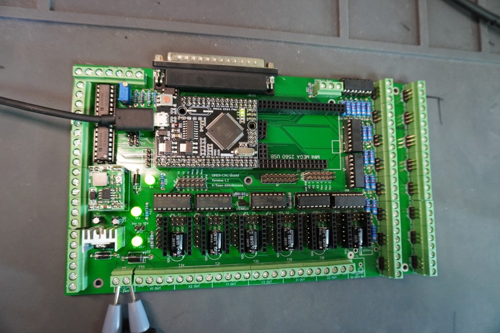
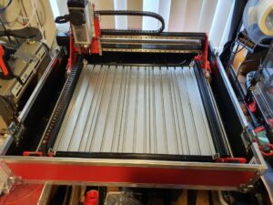
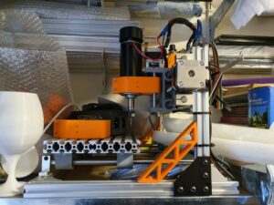
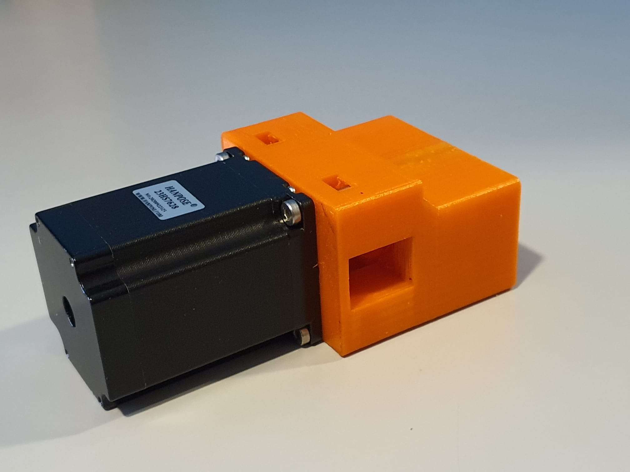
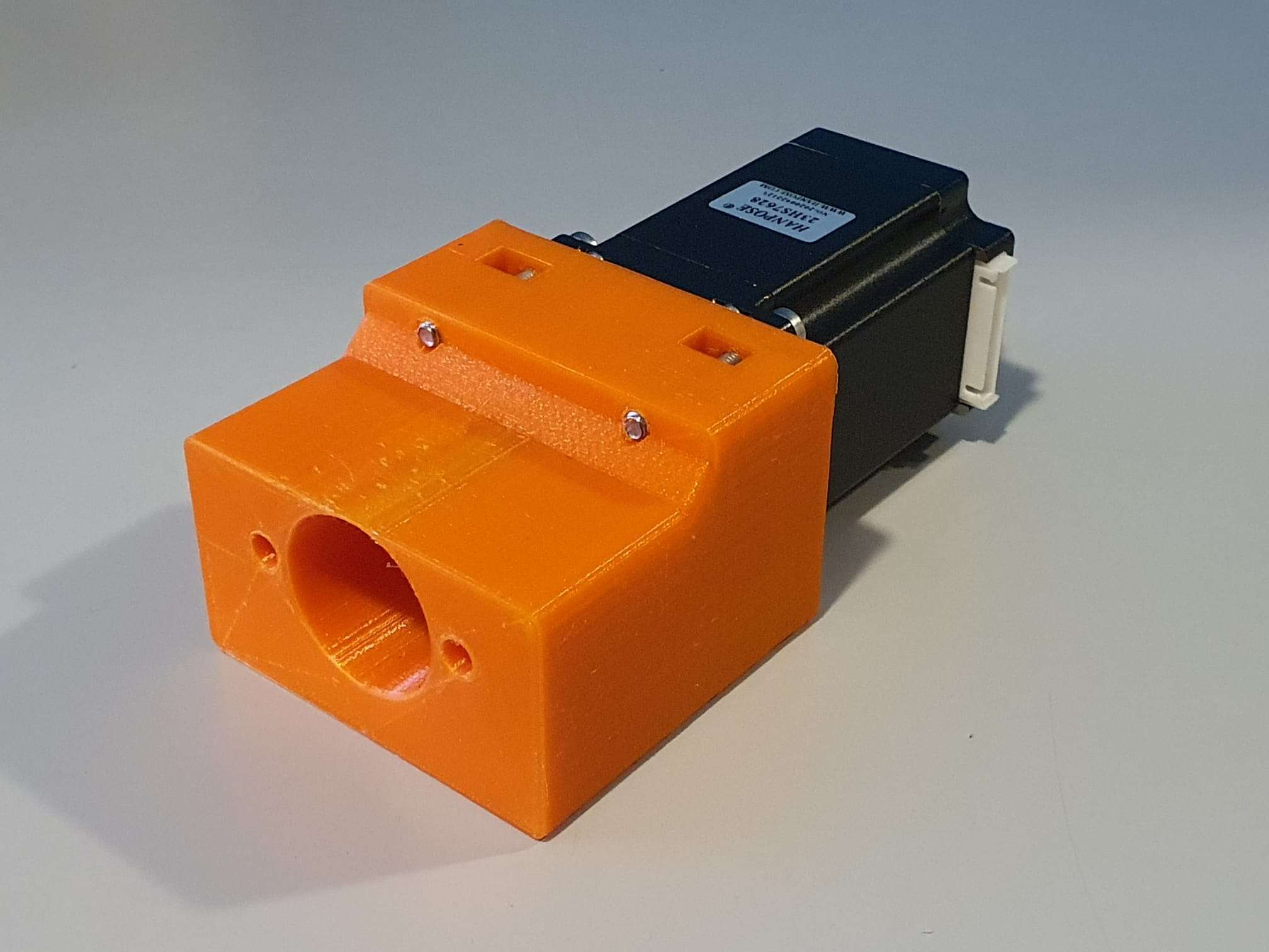
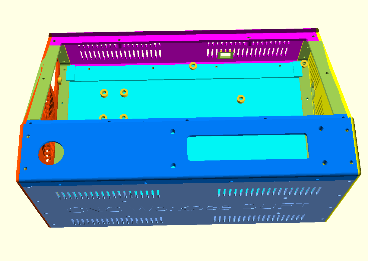
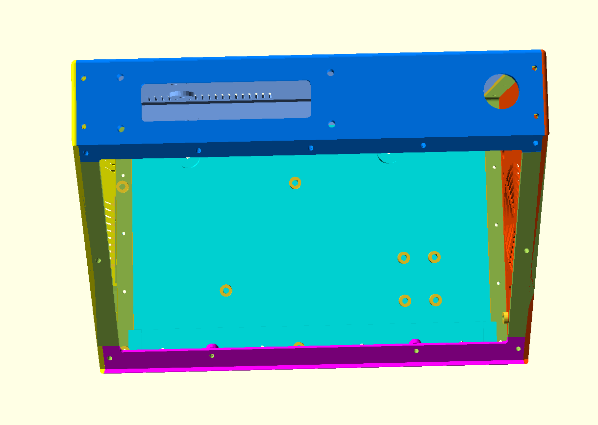
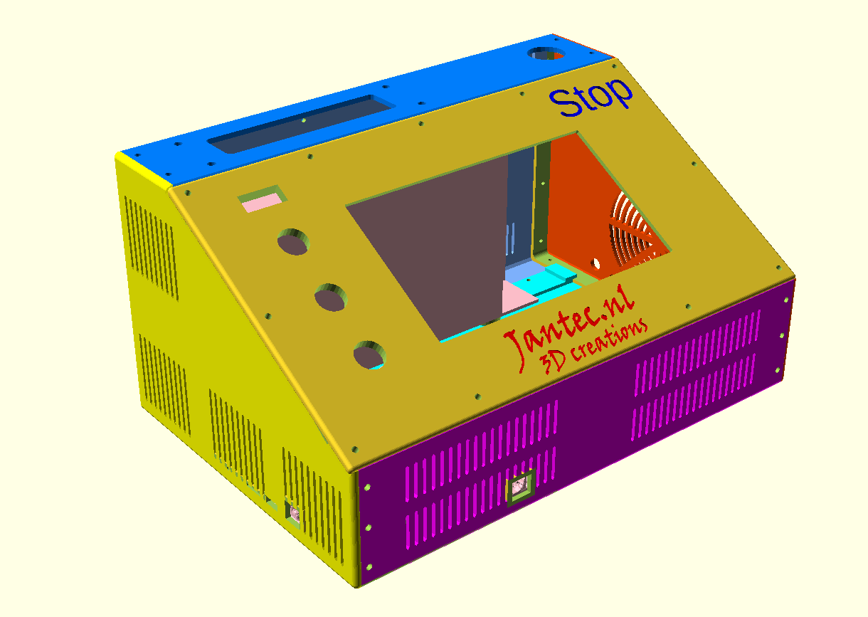
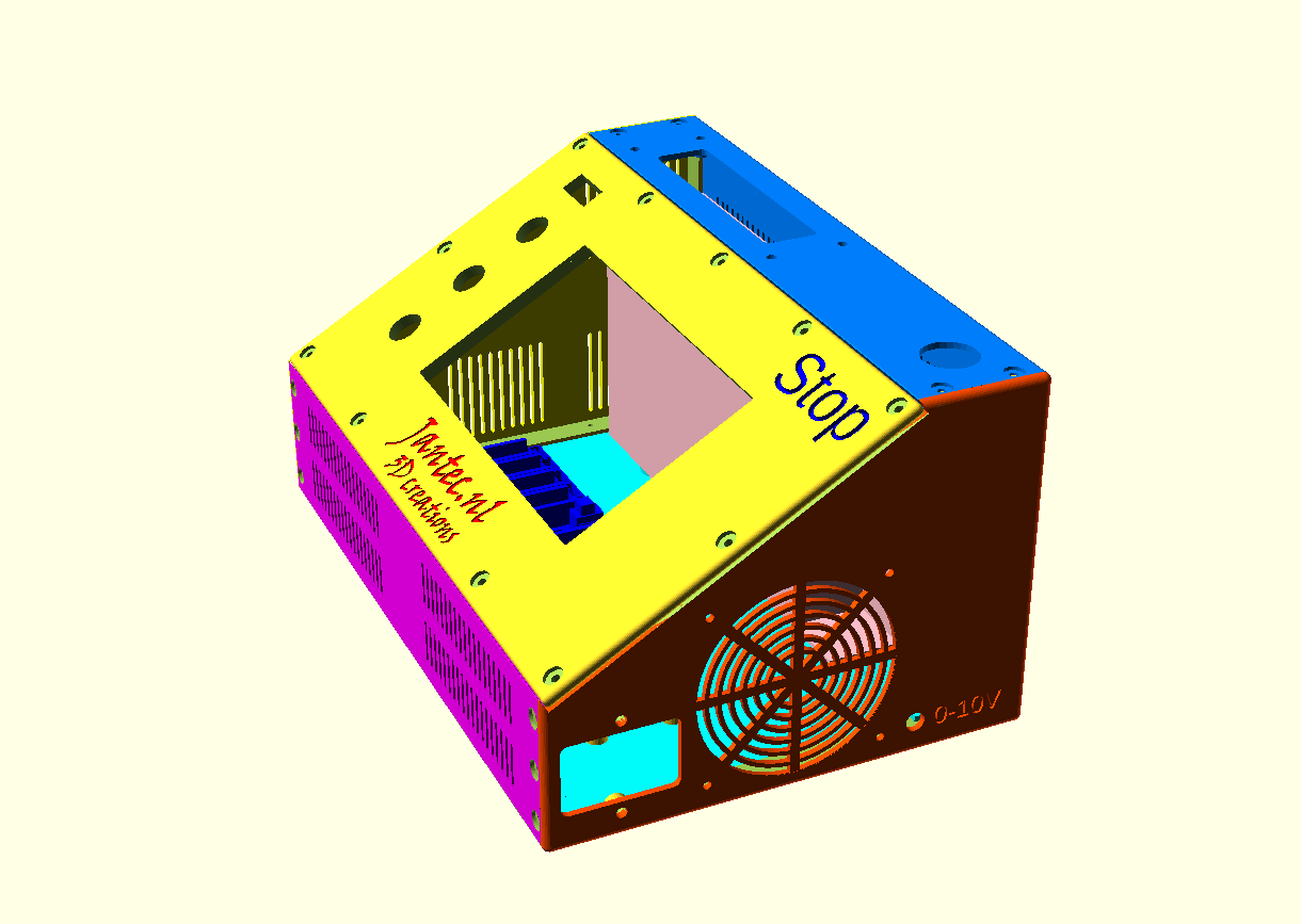
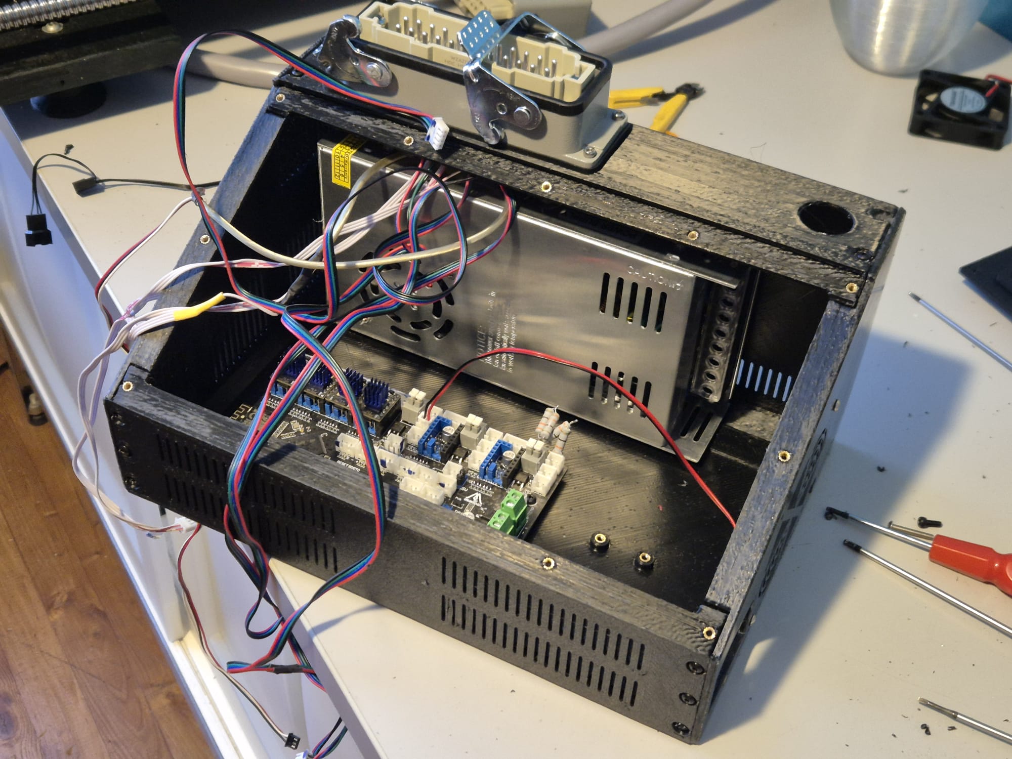
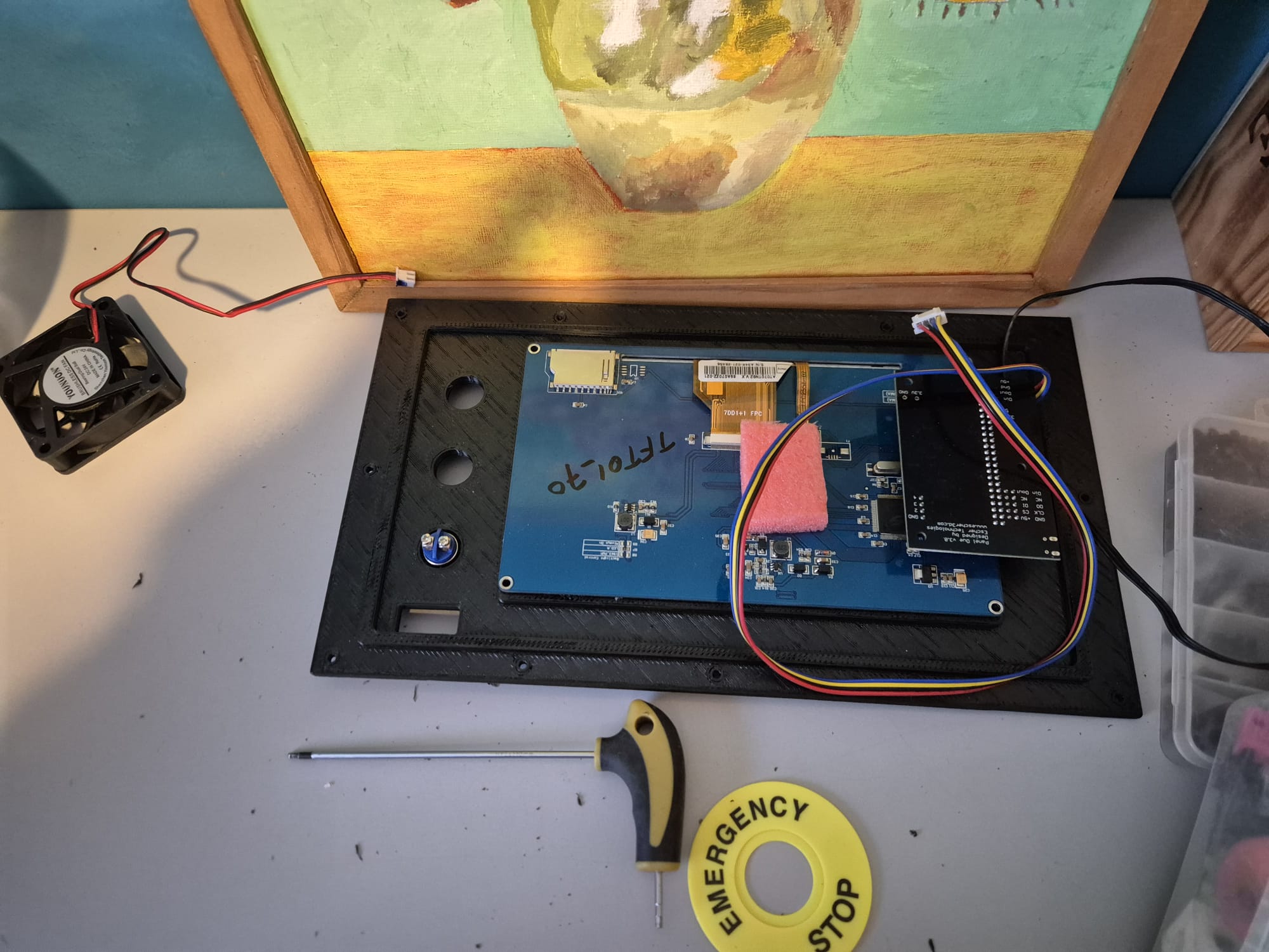
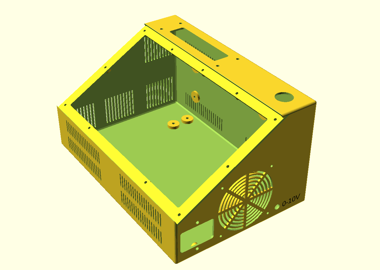
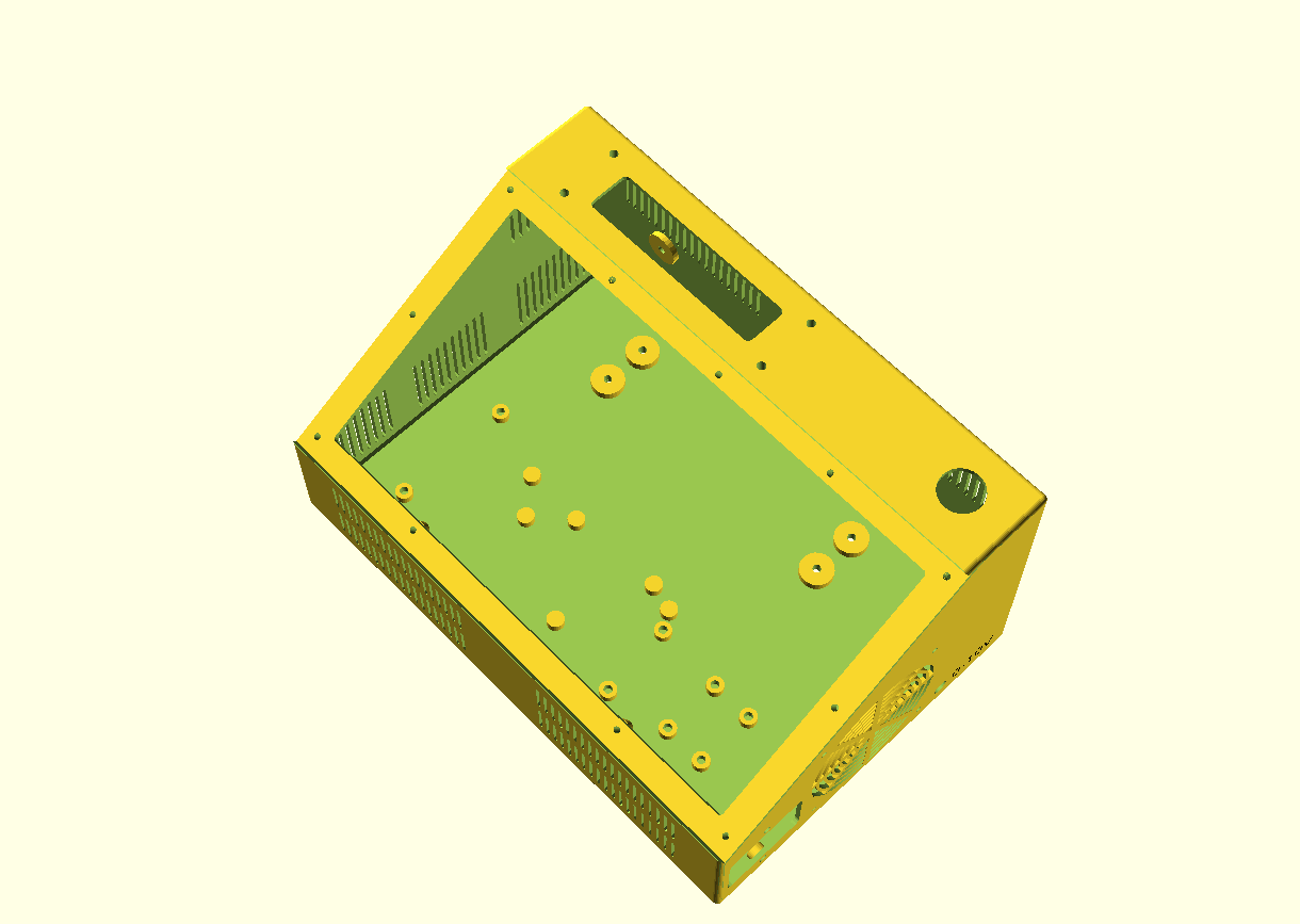
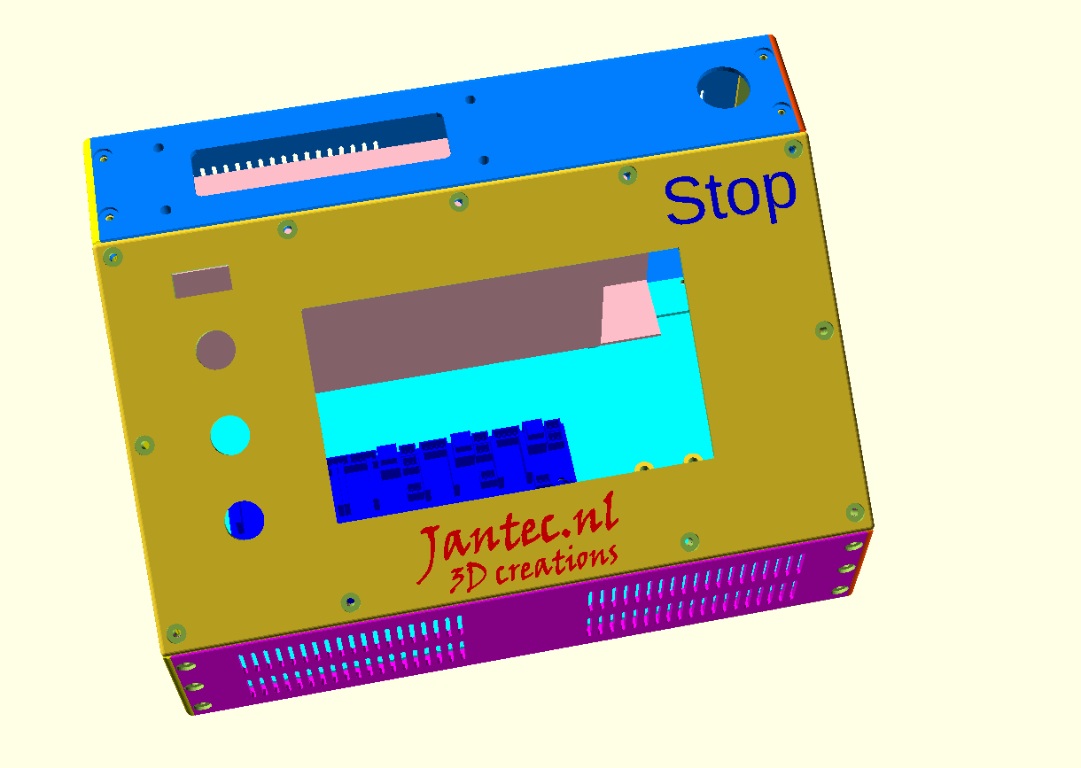
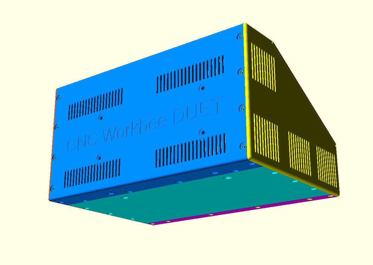
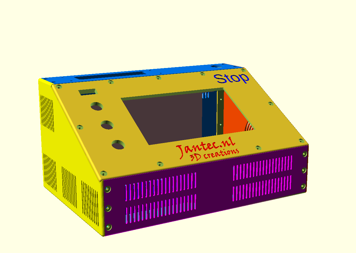
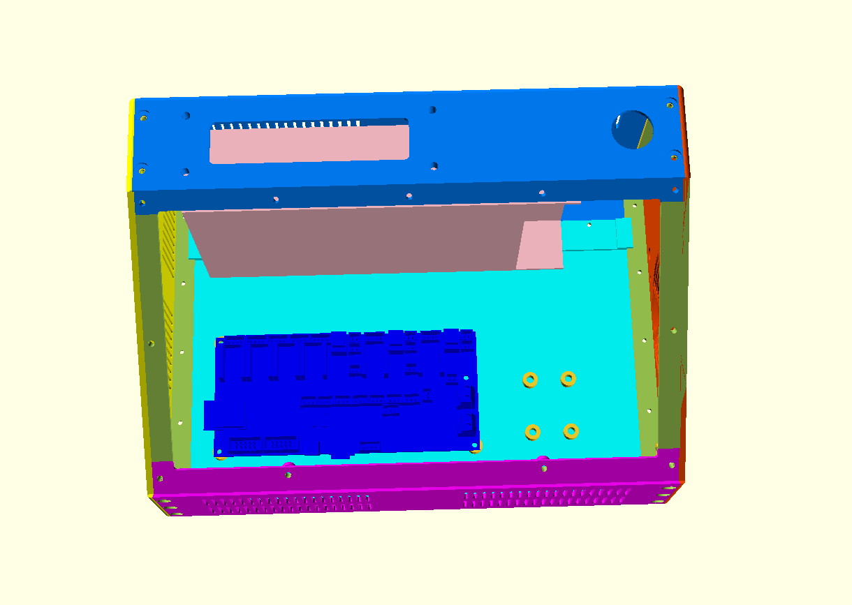
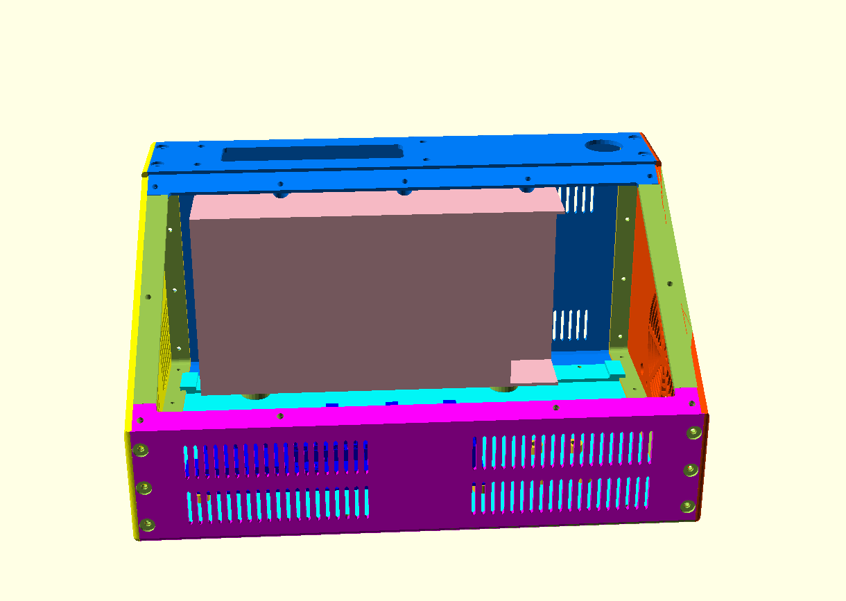
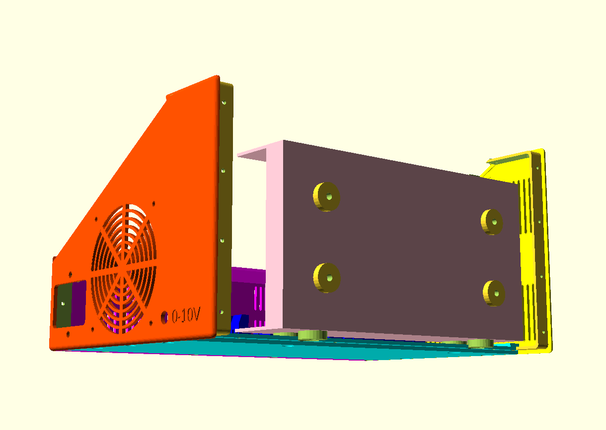
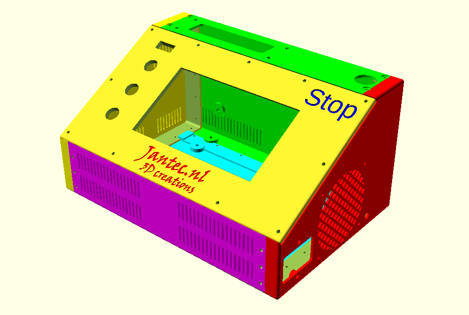
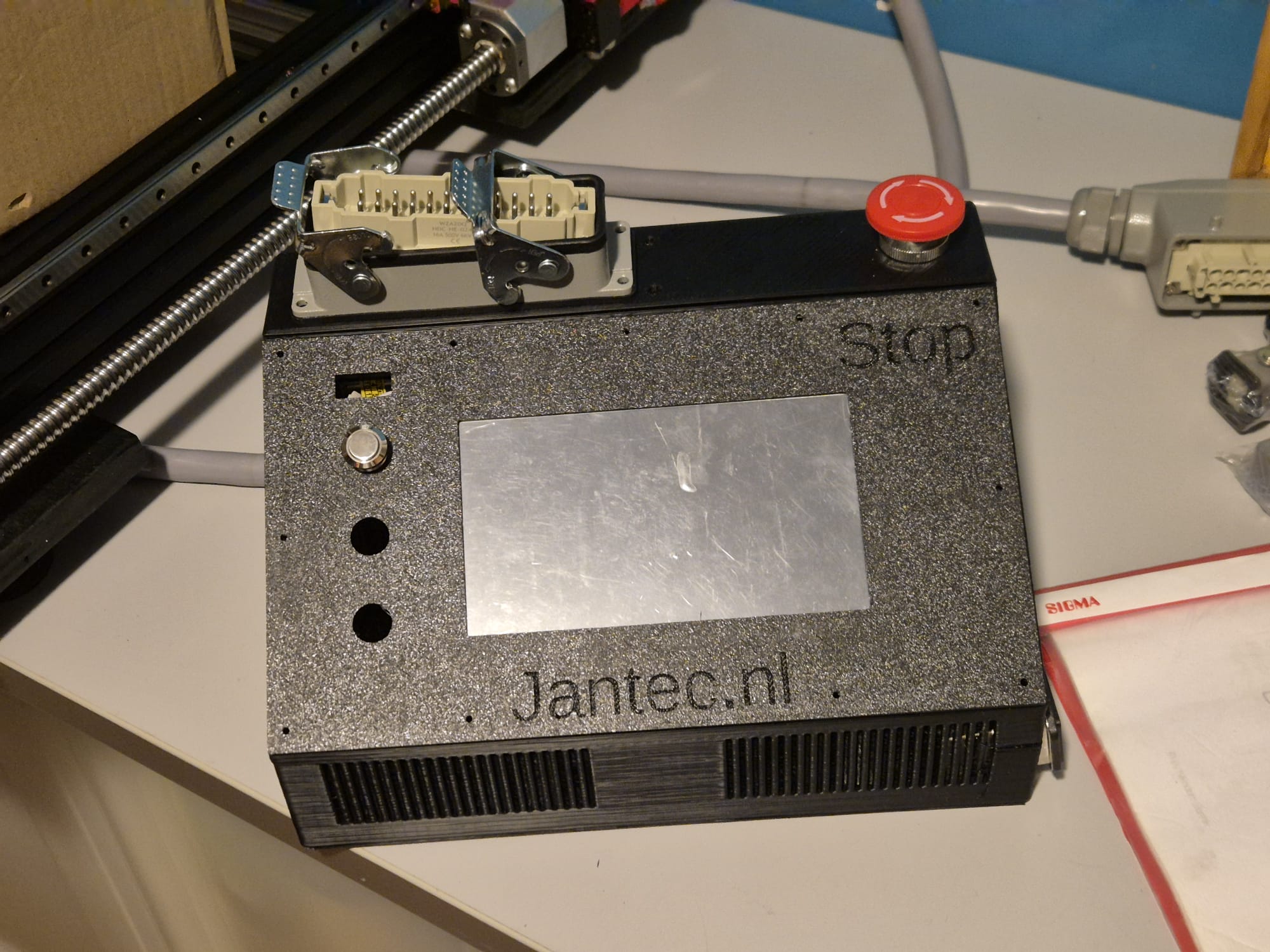
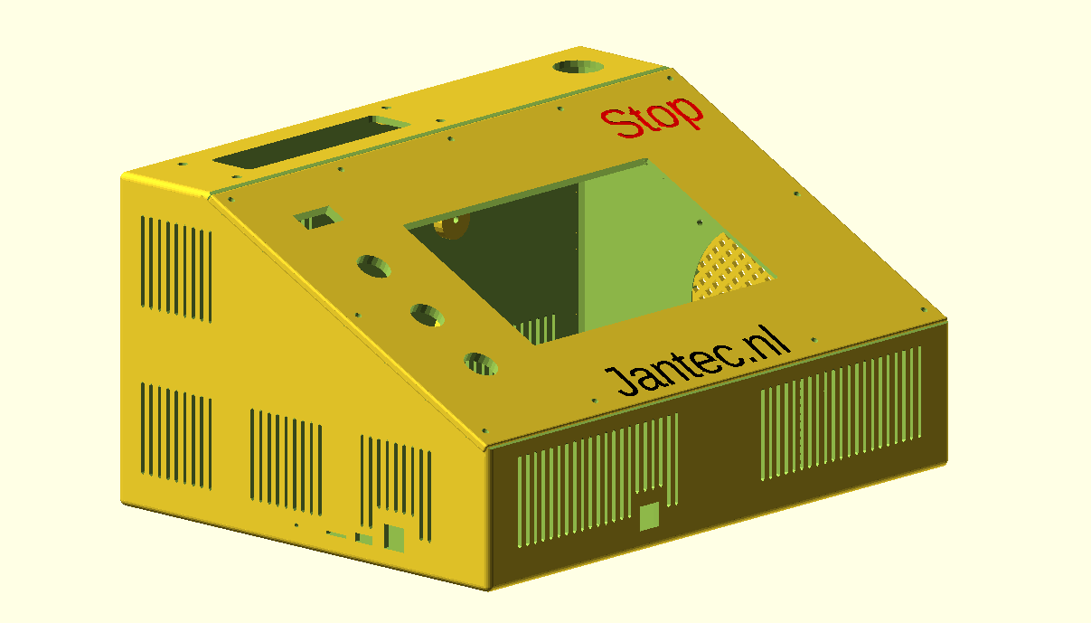
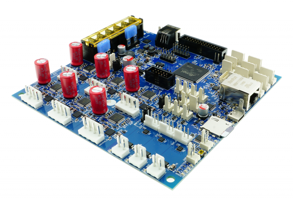
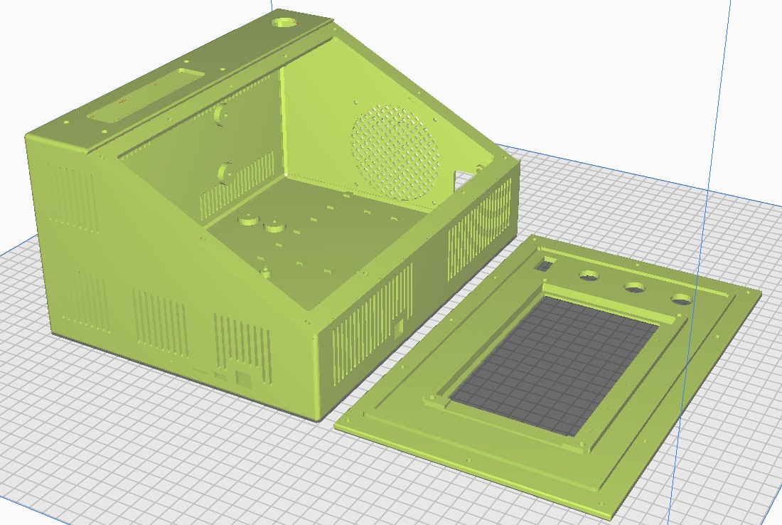
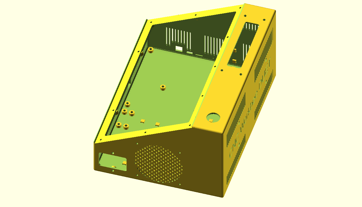
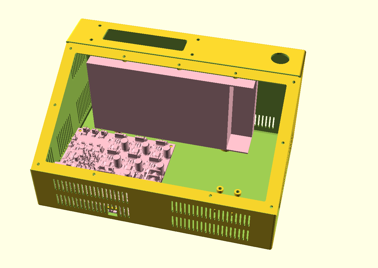
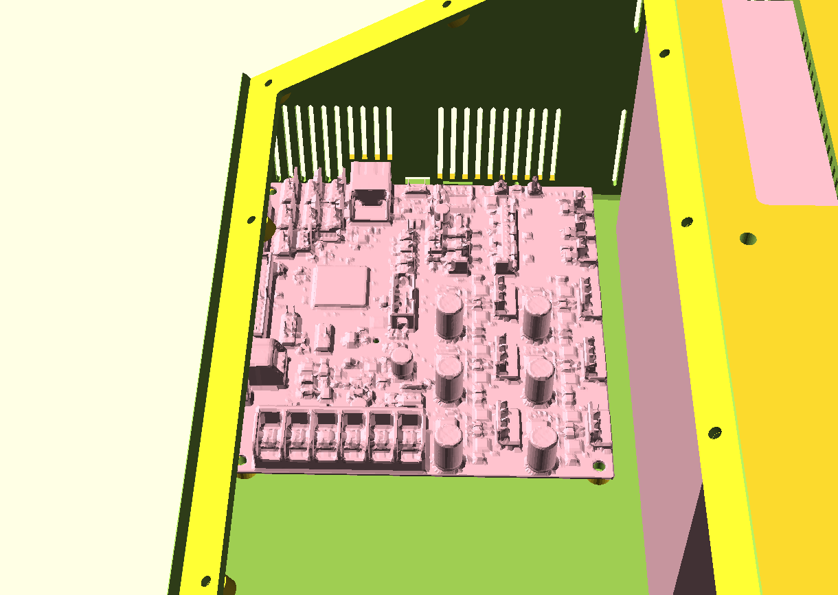
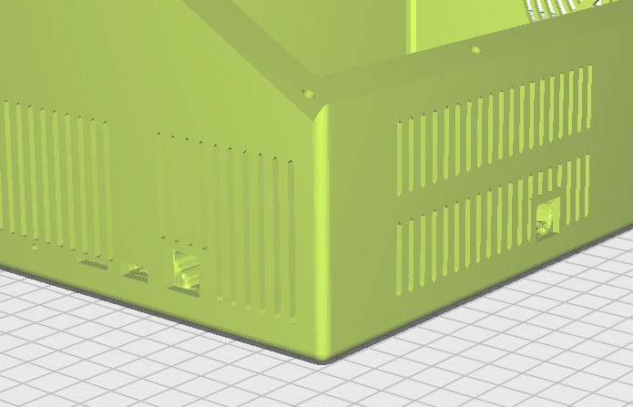
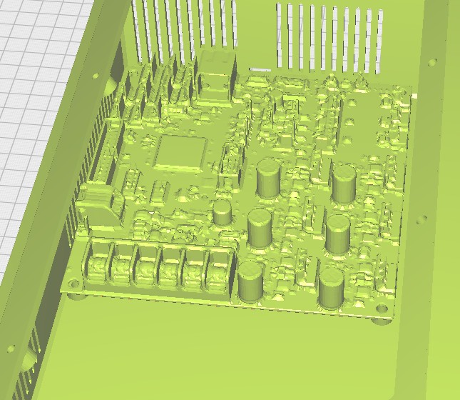
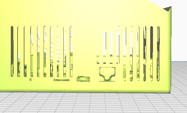
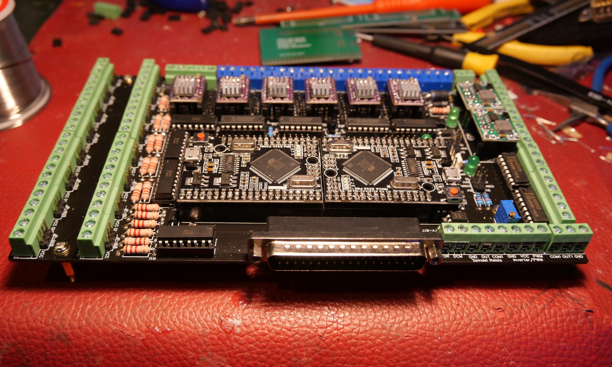
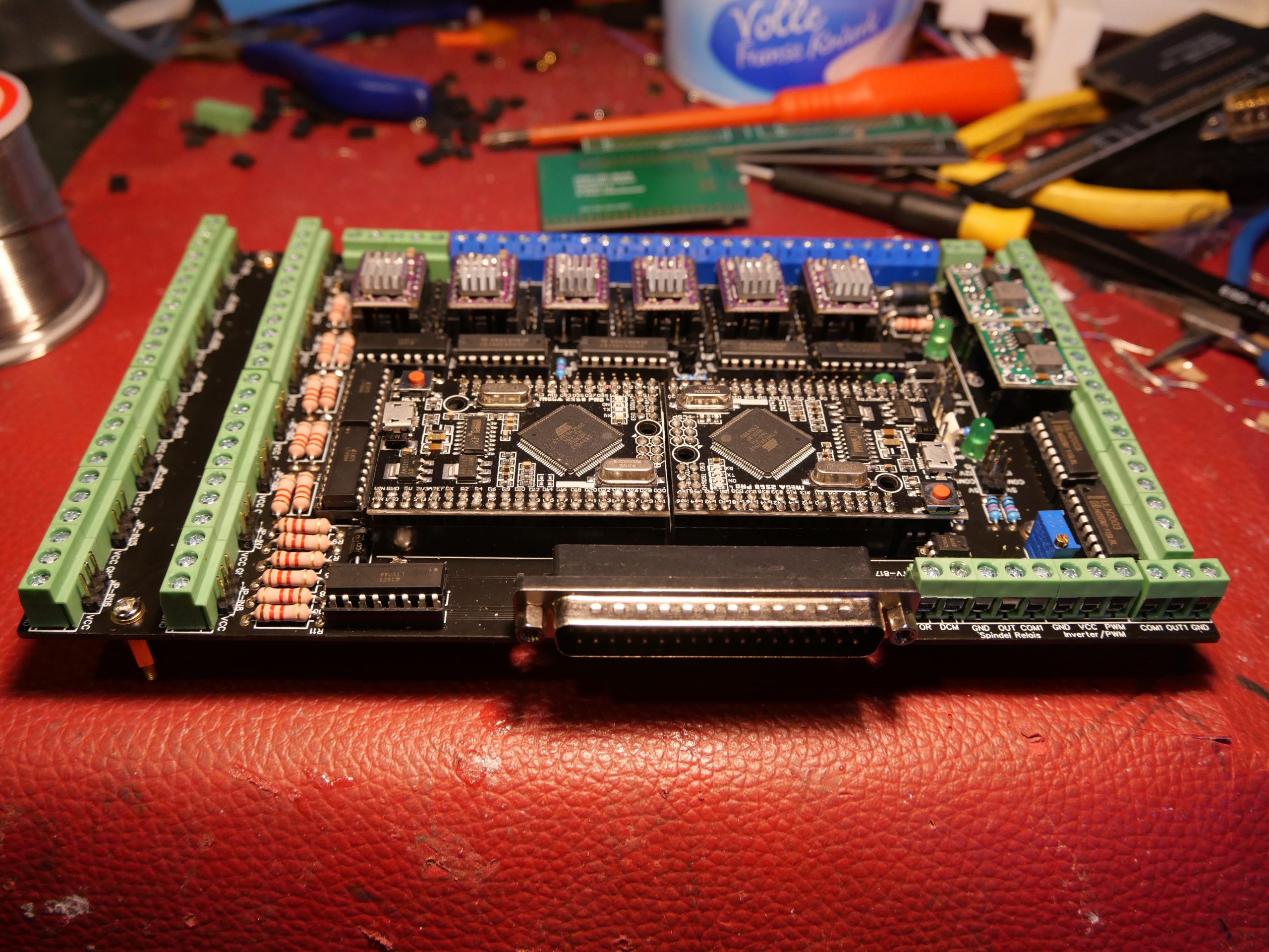
Therefore, I made the final choice to also test OPENCNC: https://blog.altholtmann.com/open-cnc-shield/
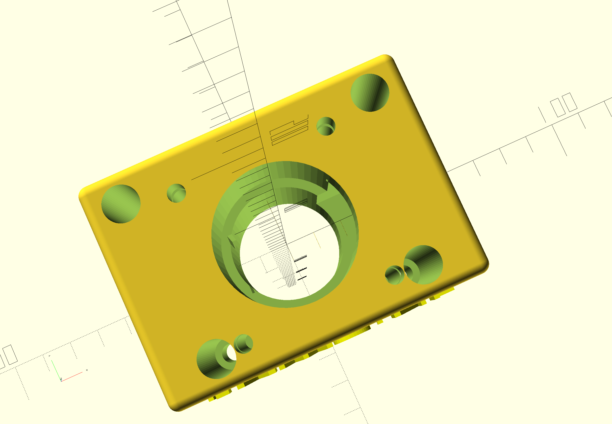
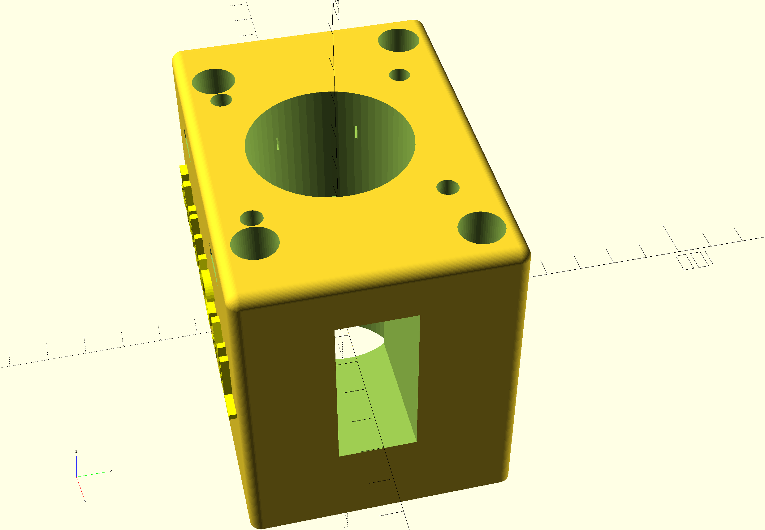
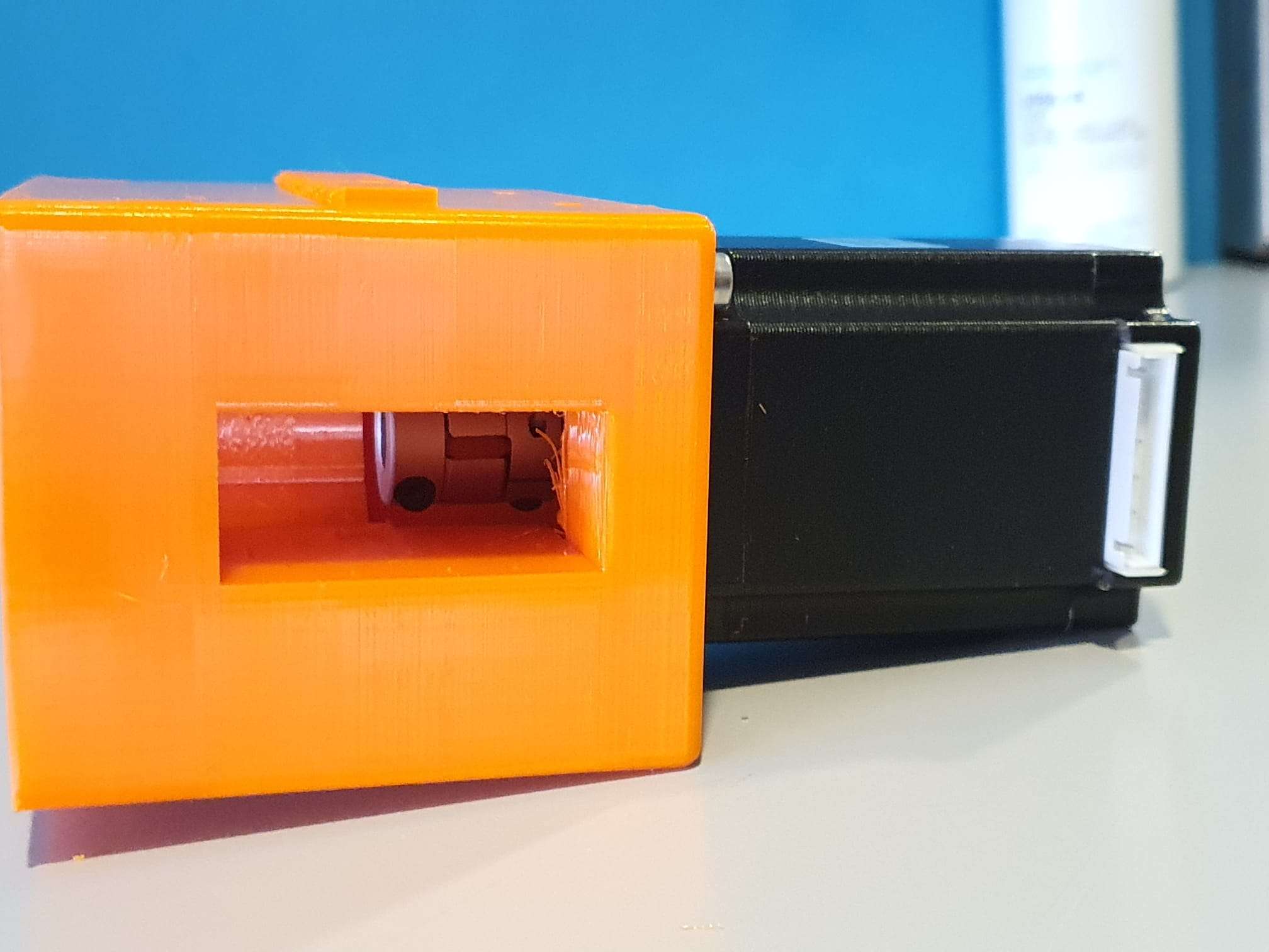
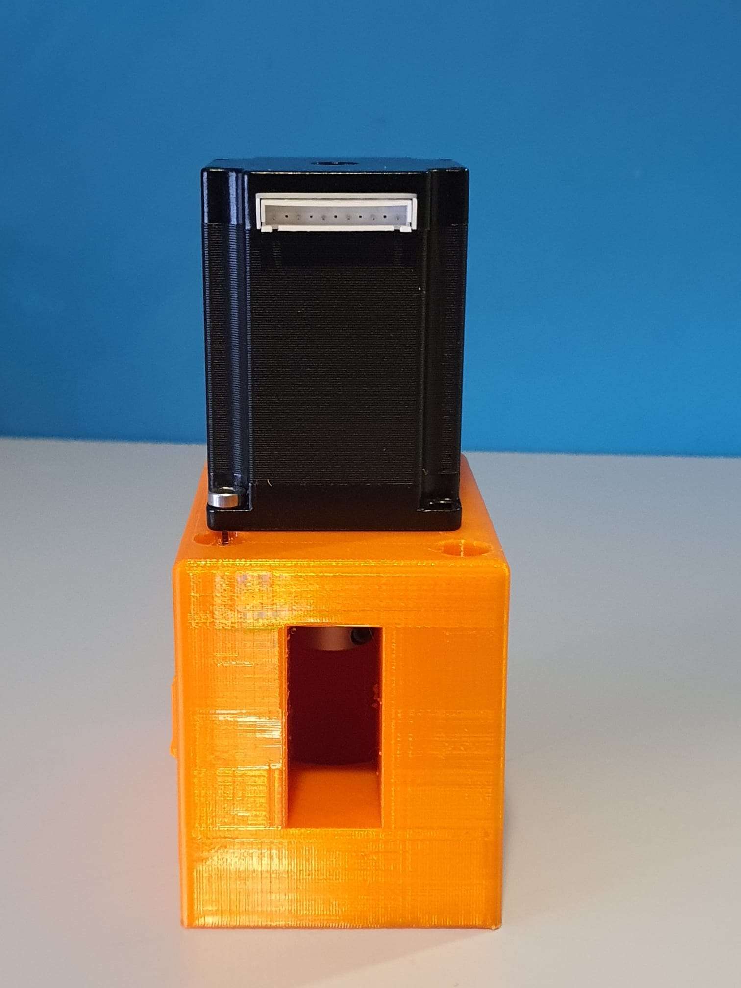
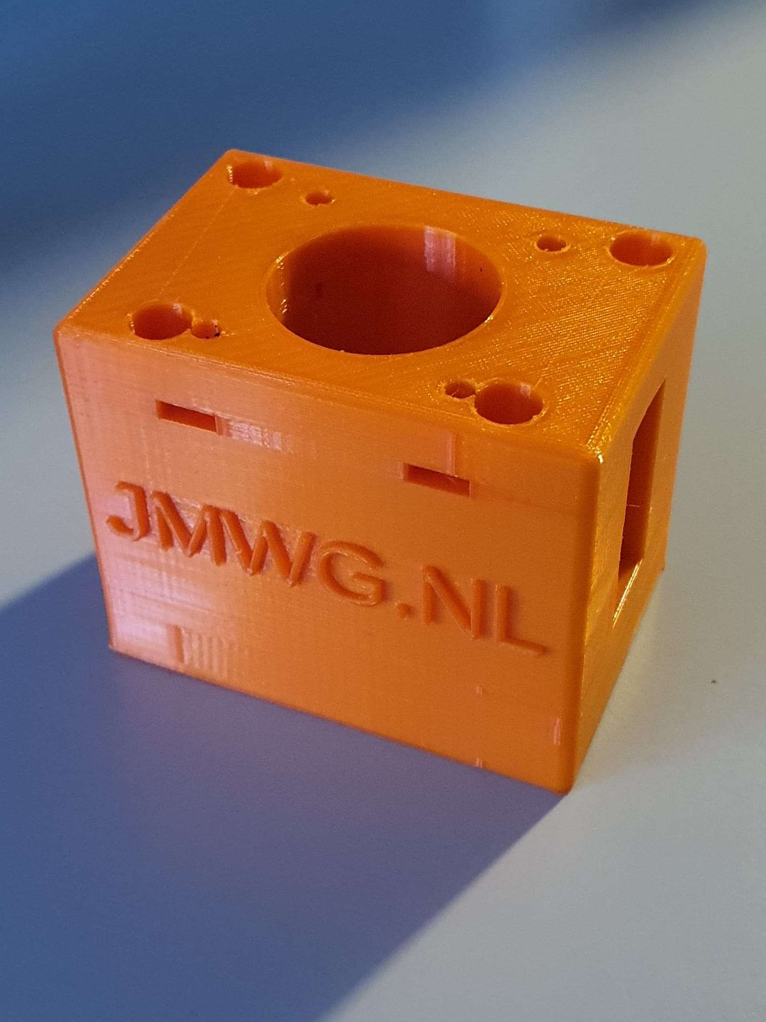
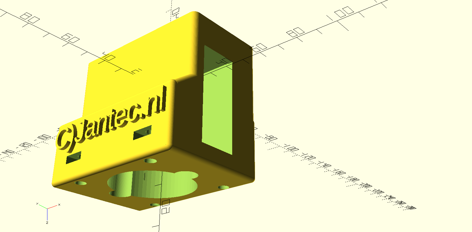
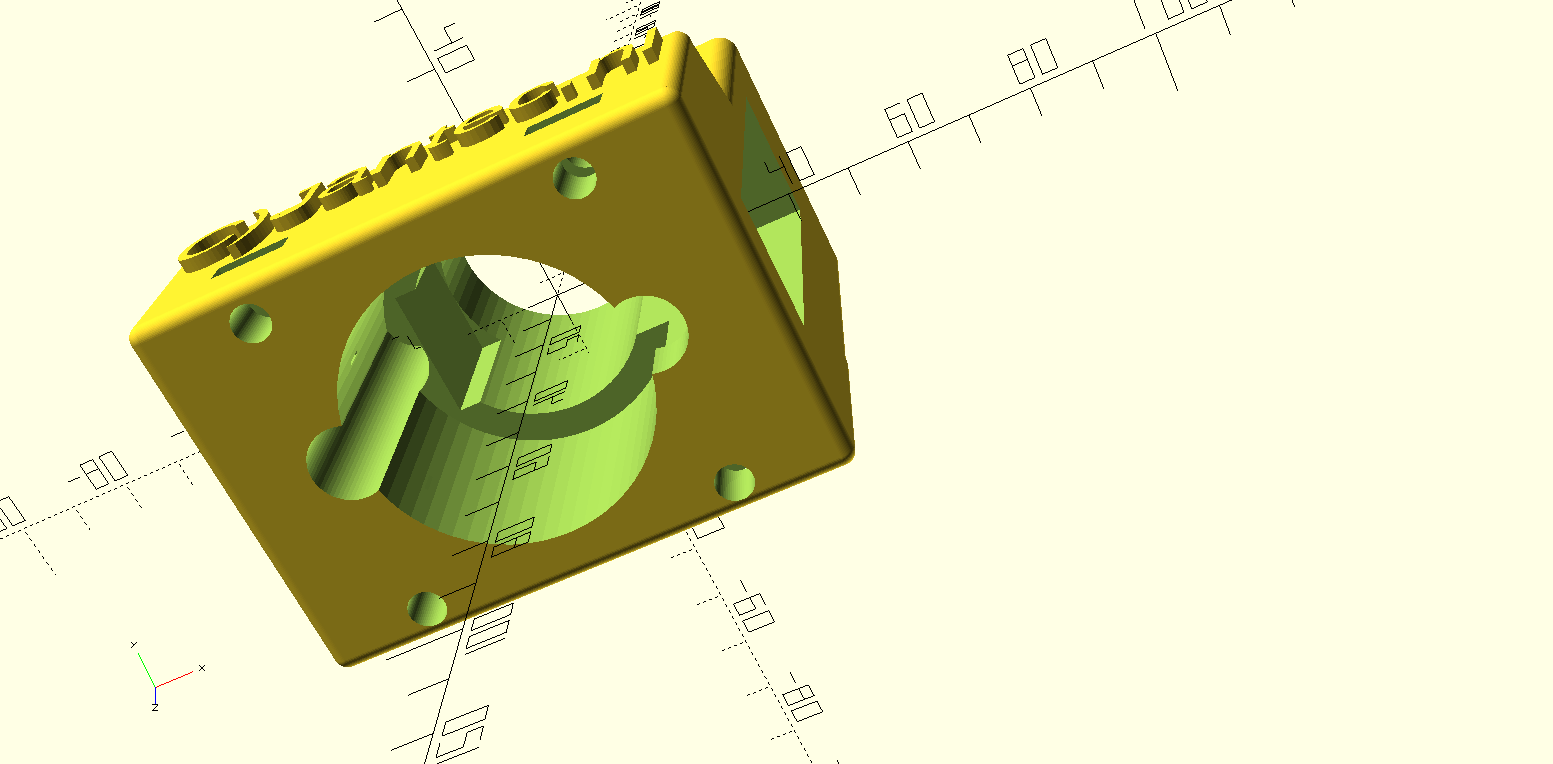
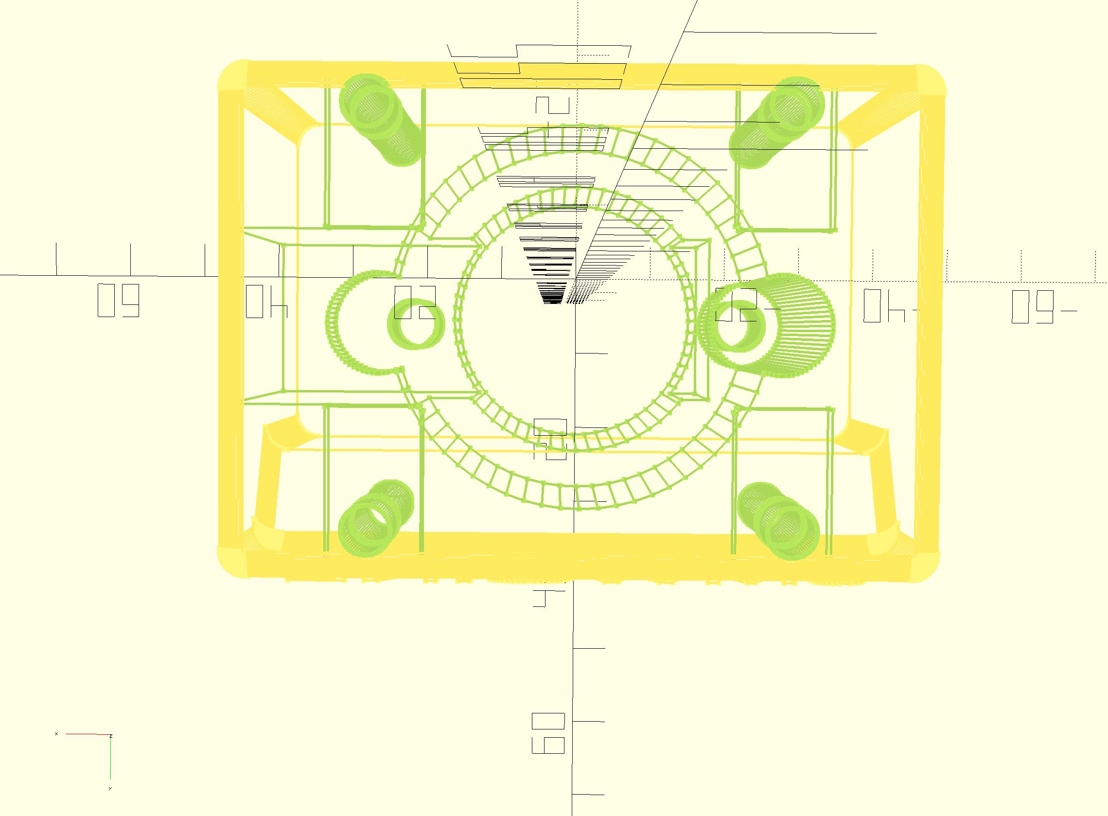
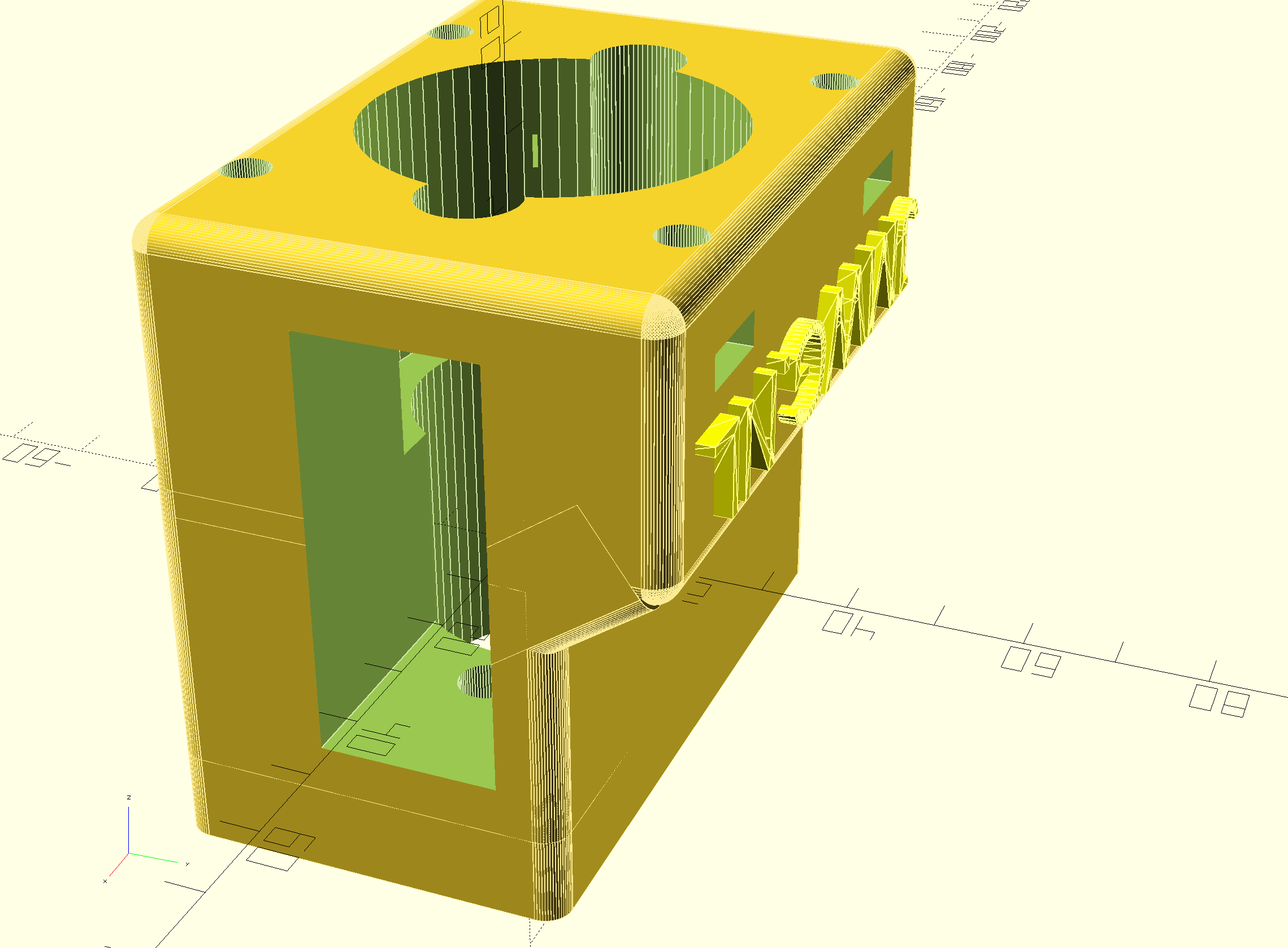
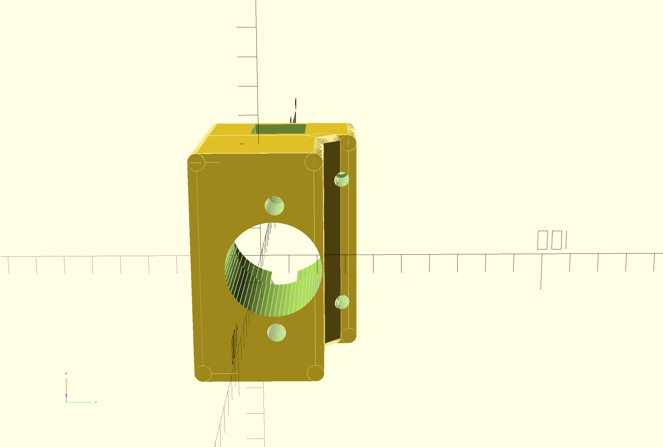
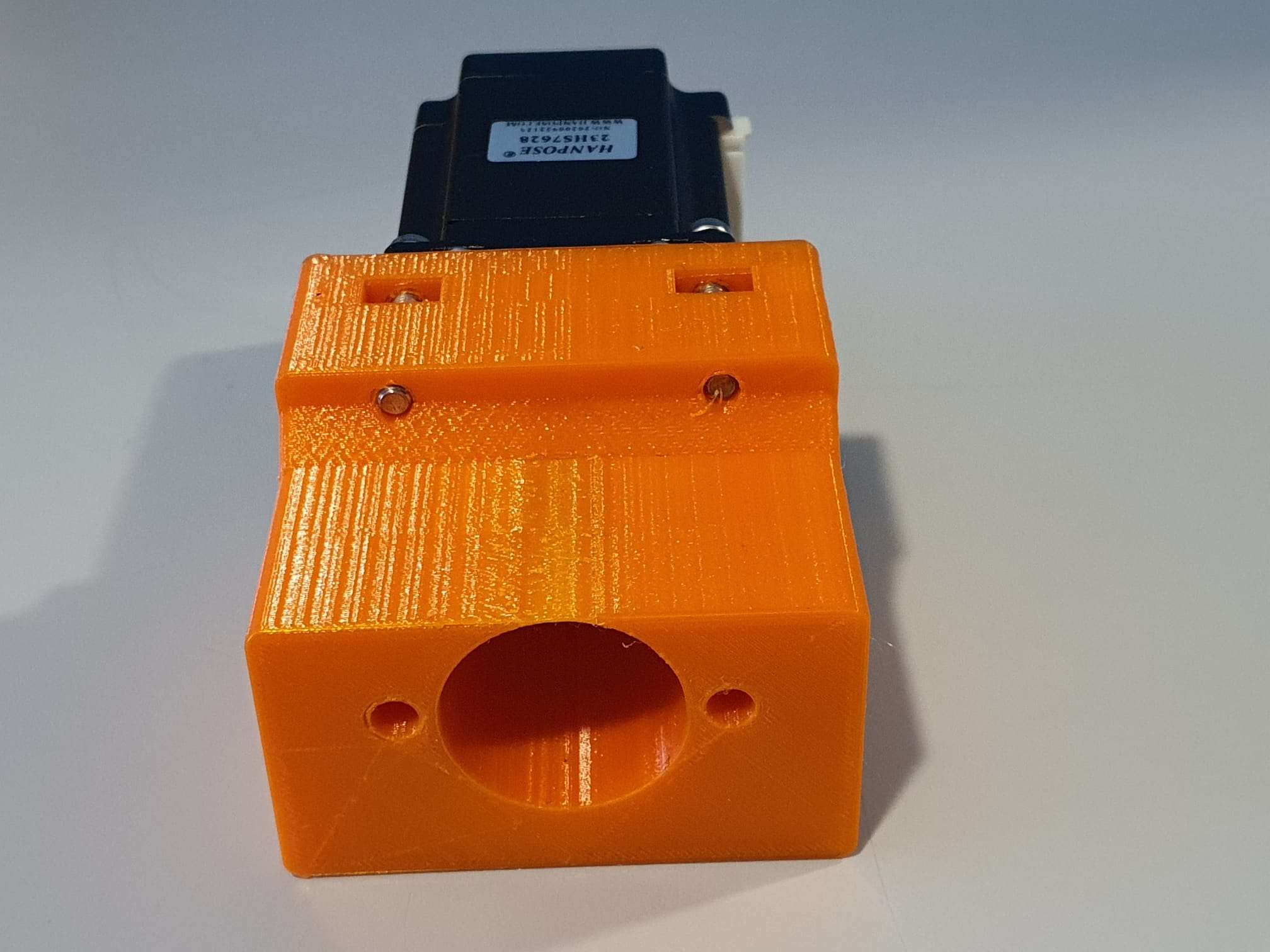
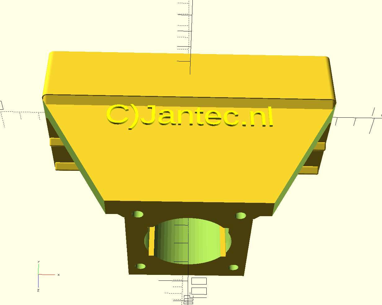
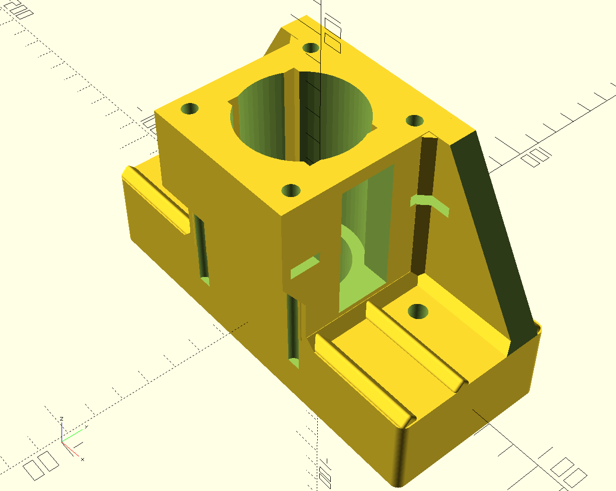
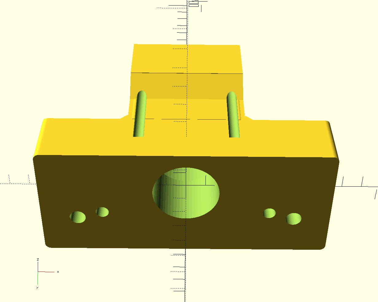
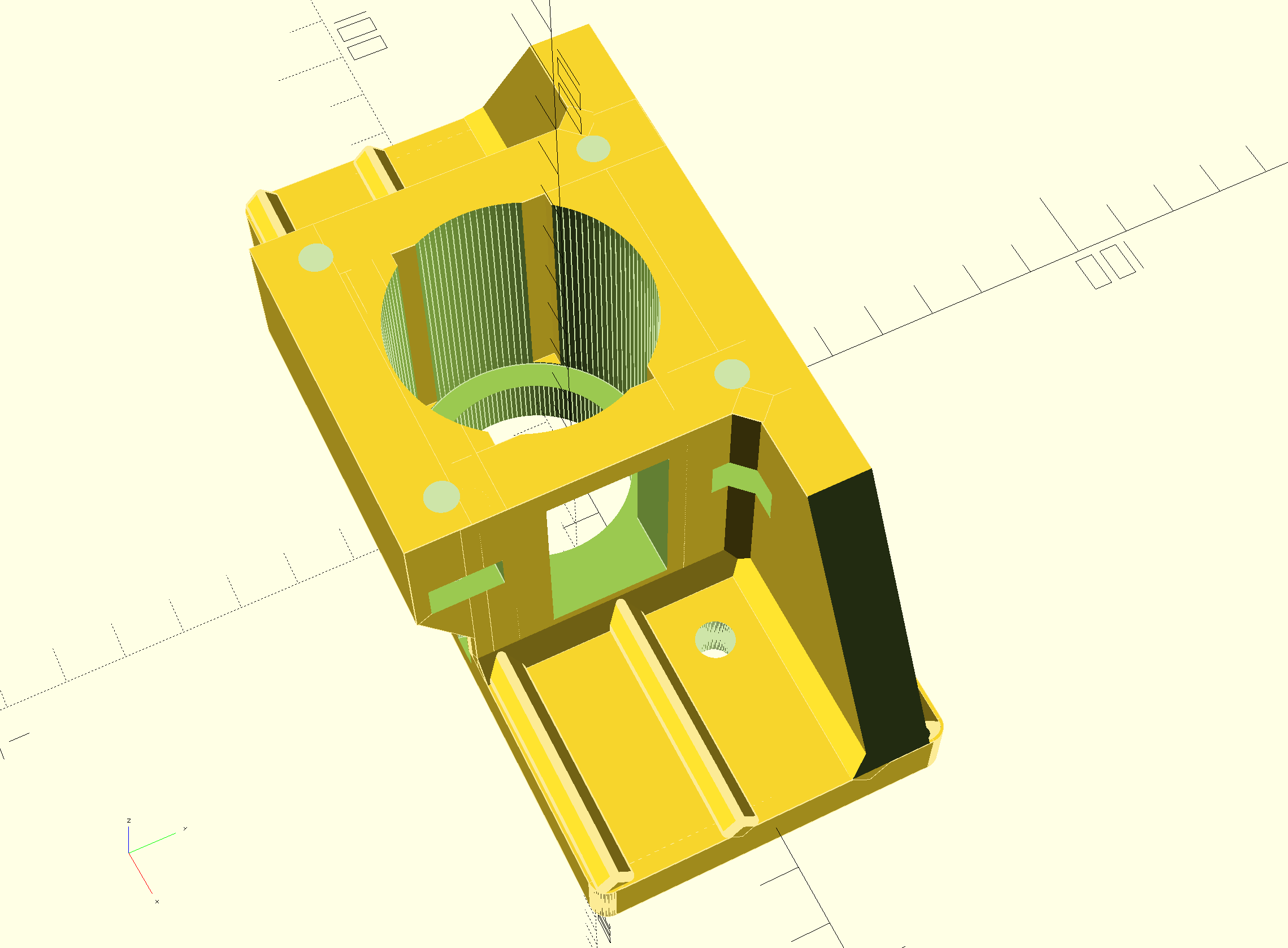
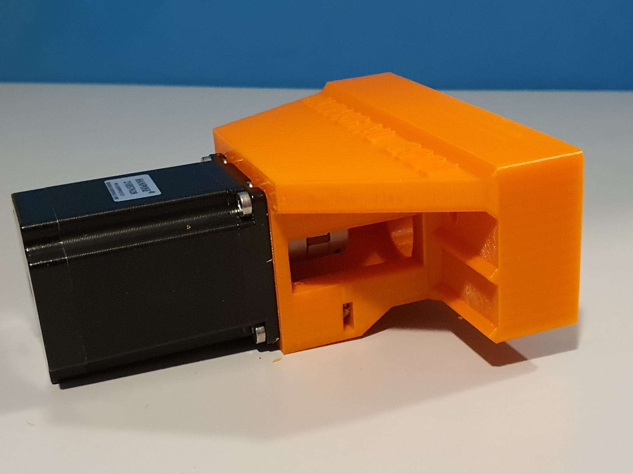
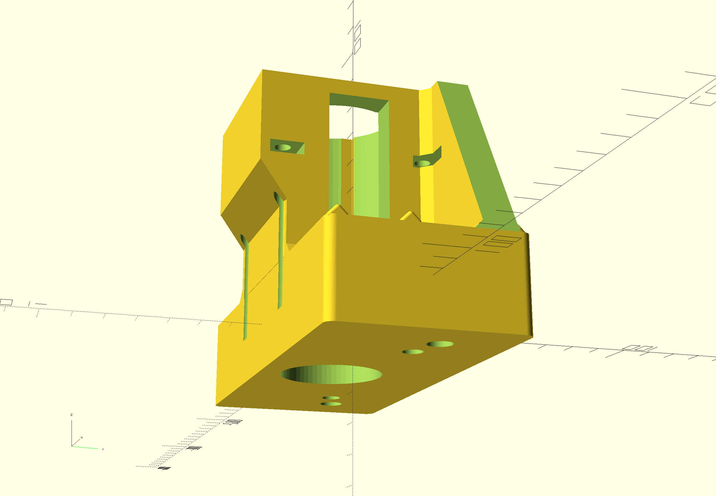
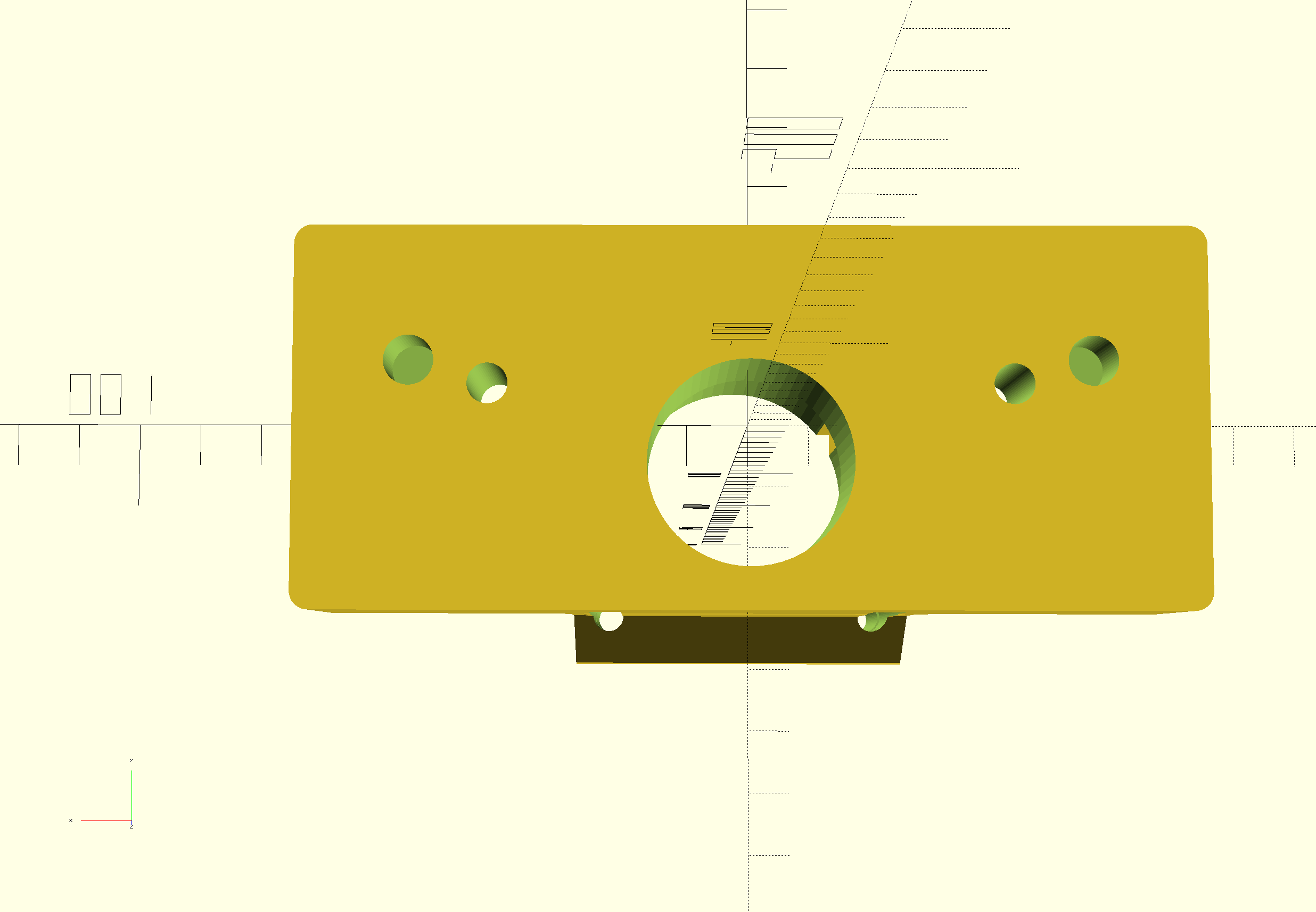
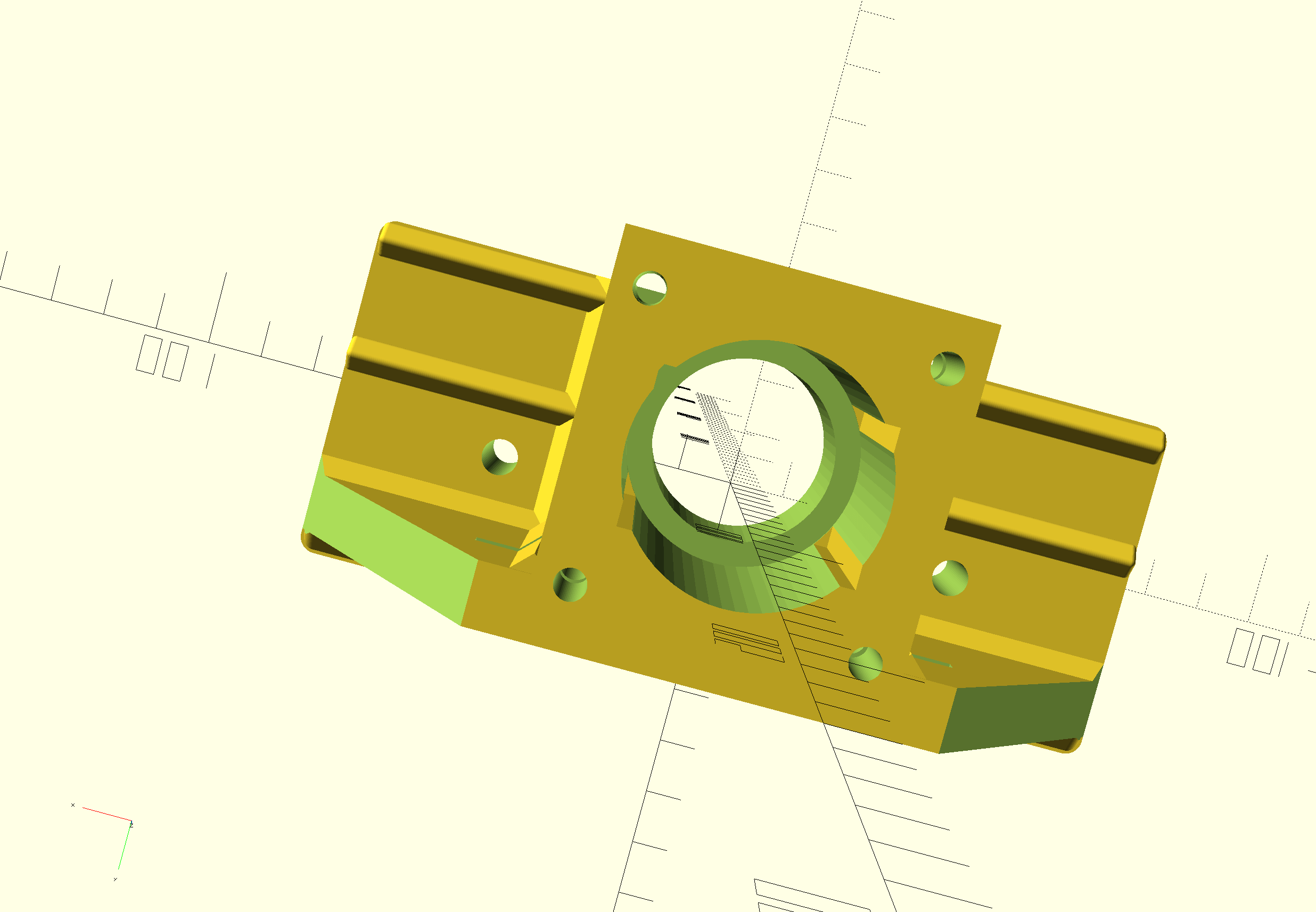
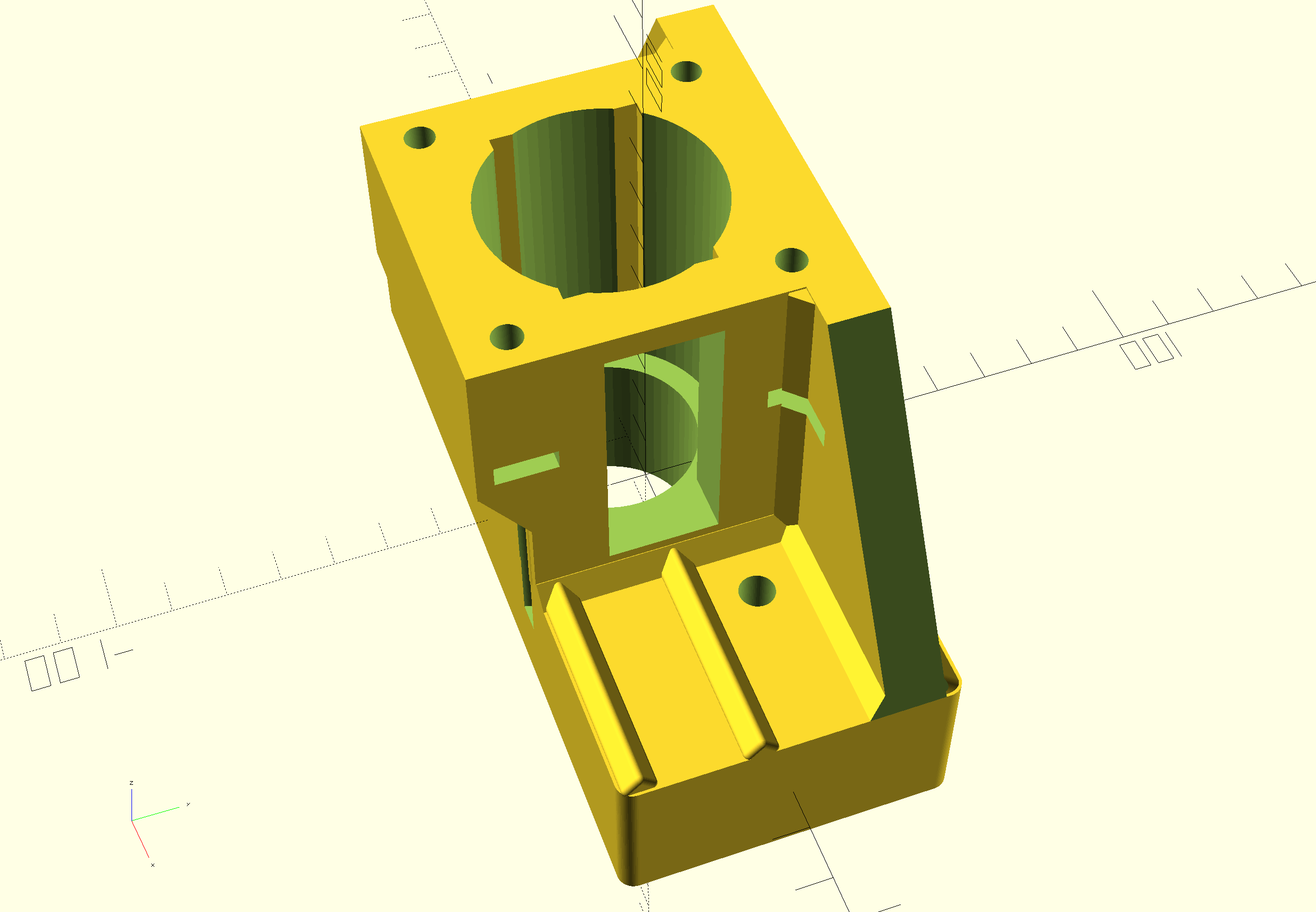
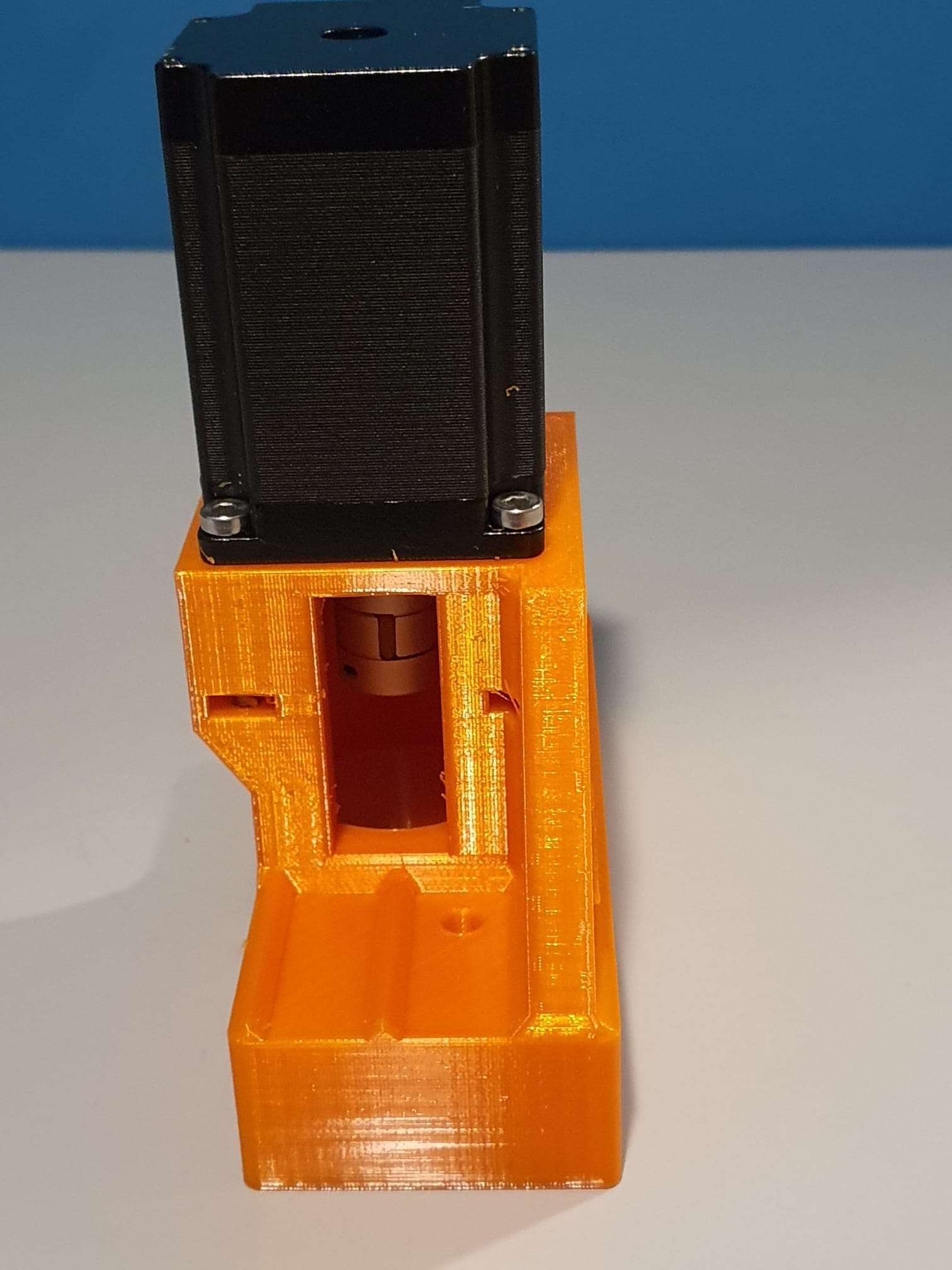
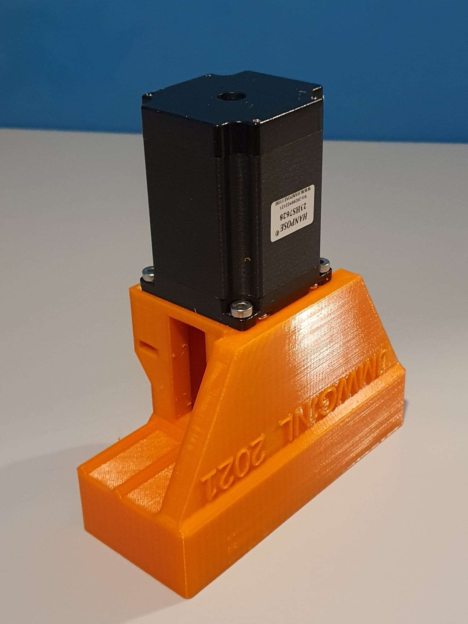
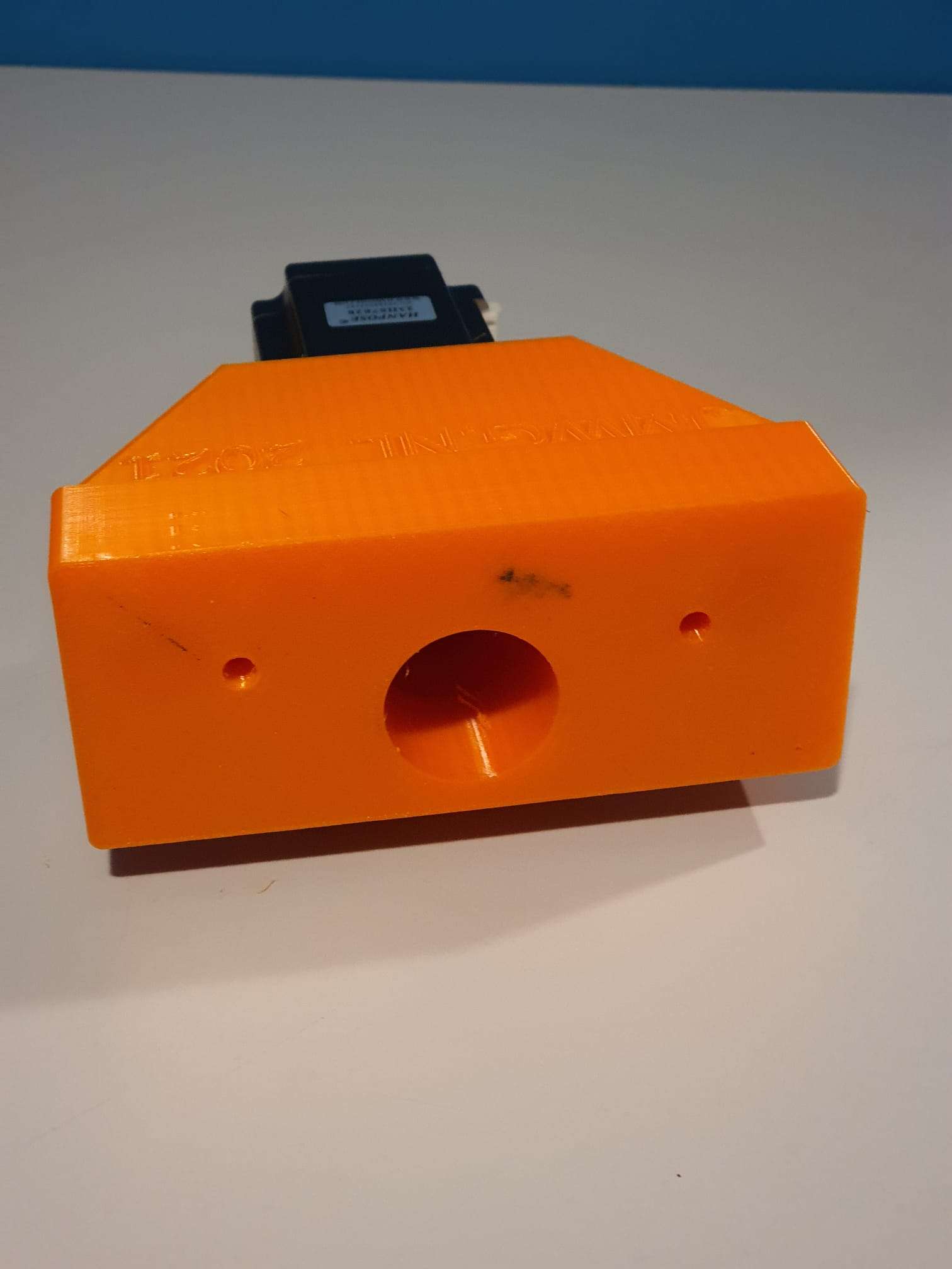
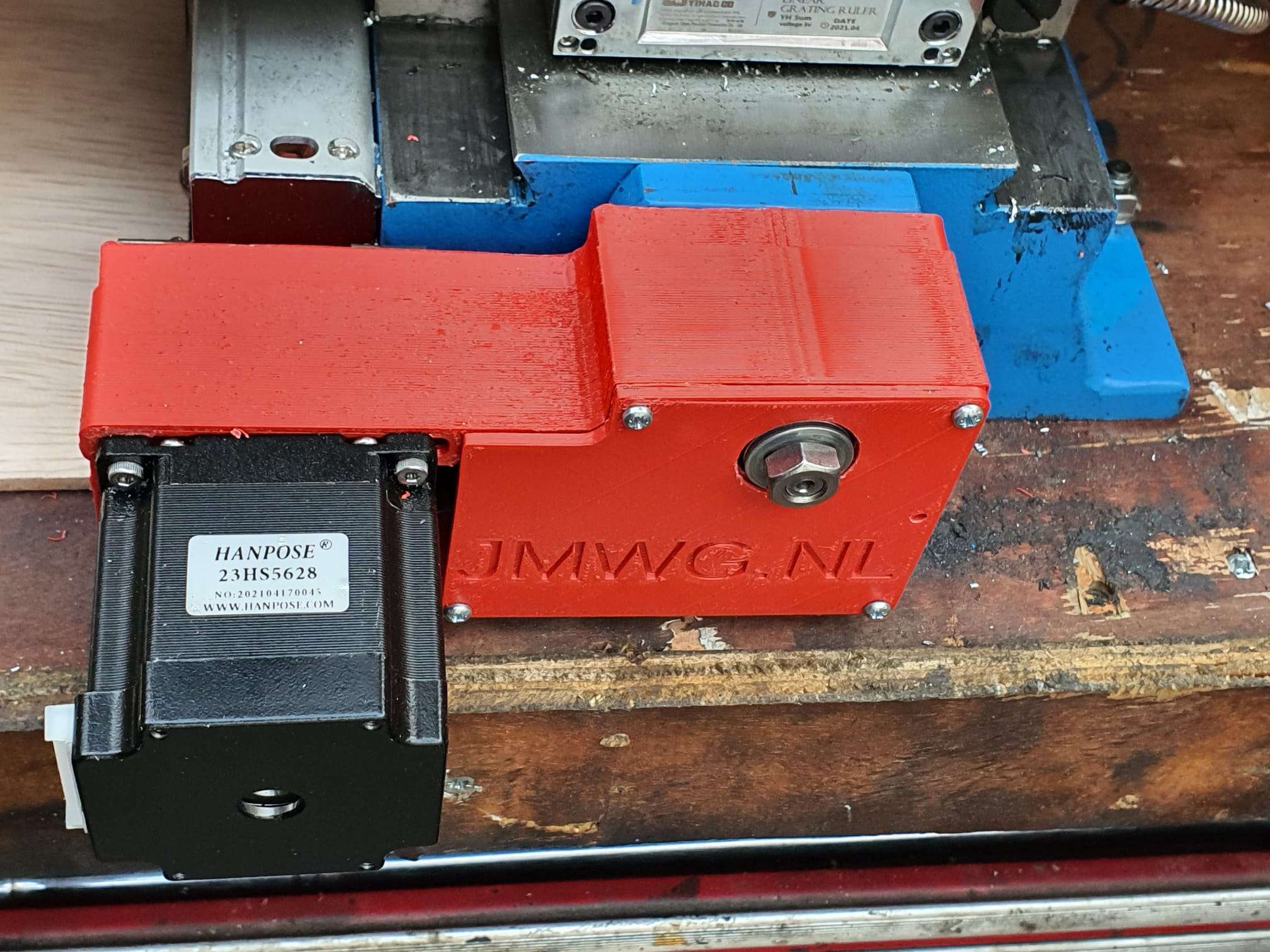
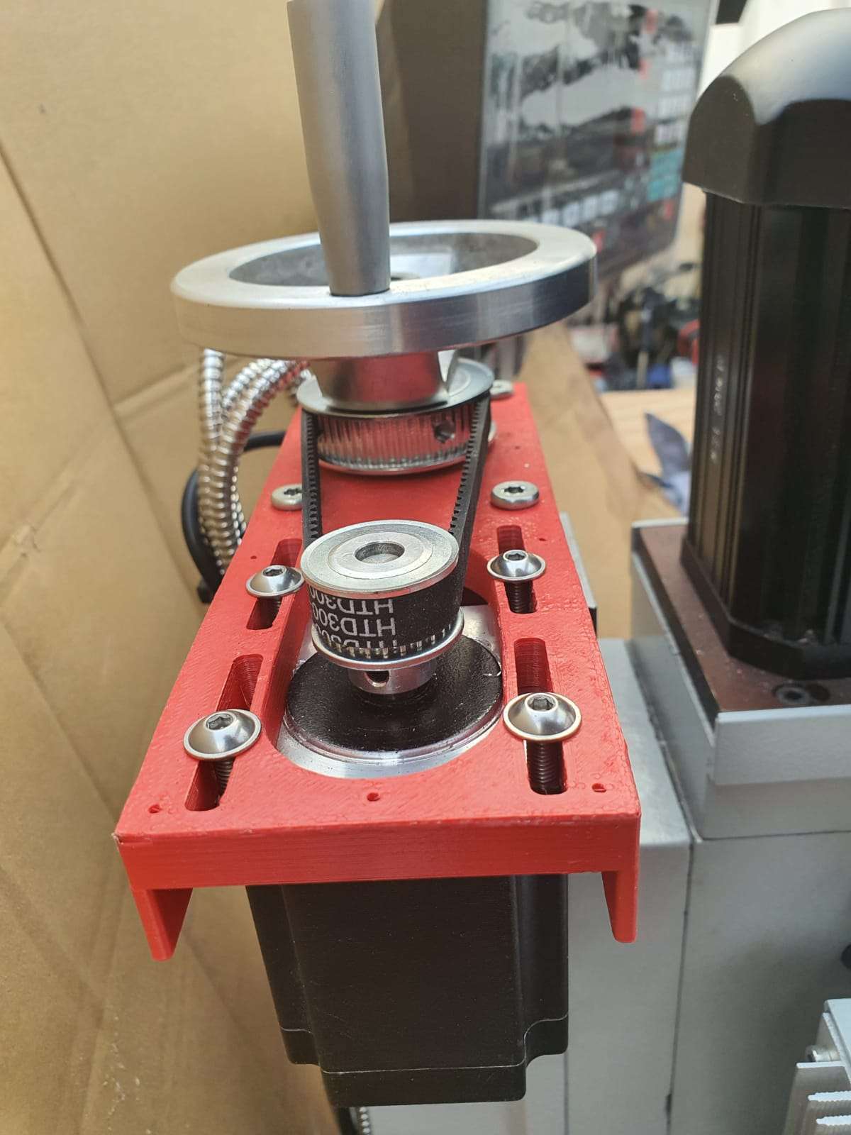
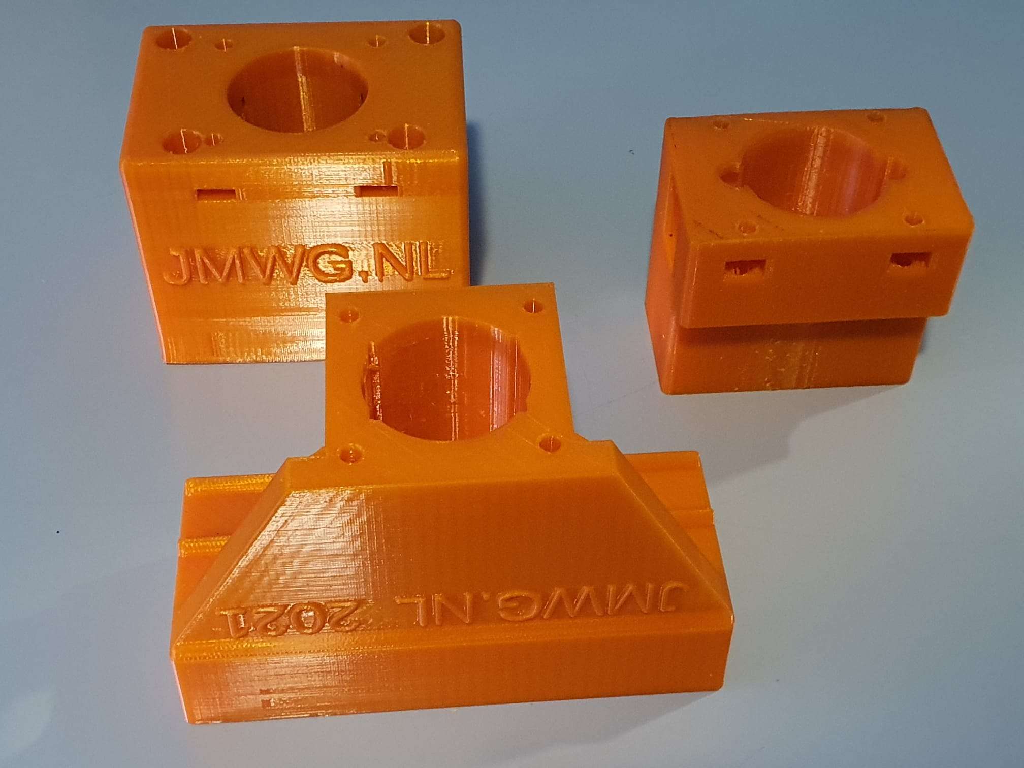
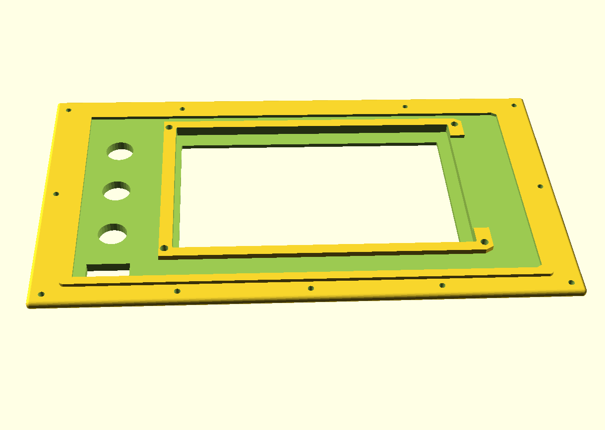
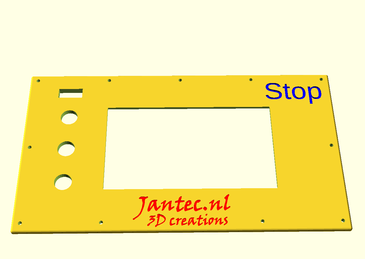
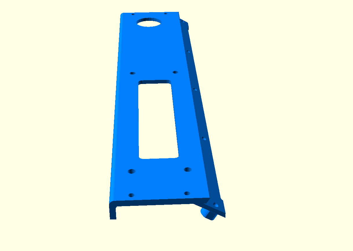
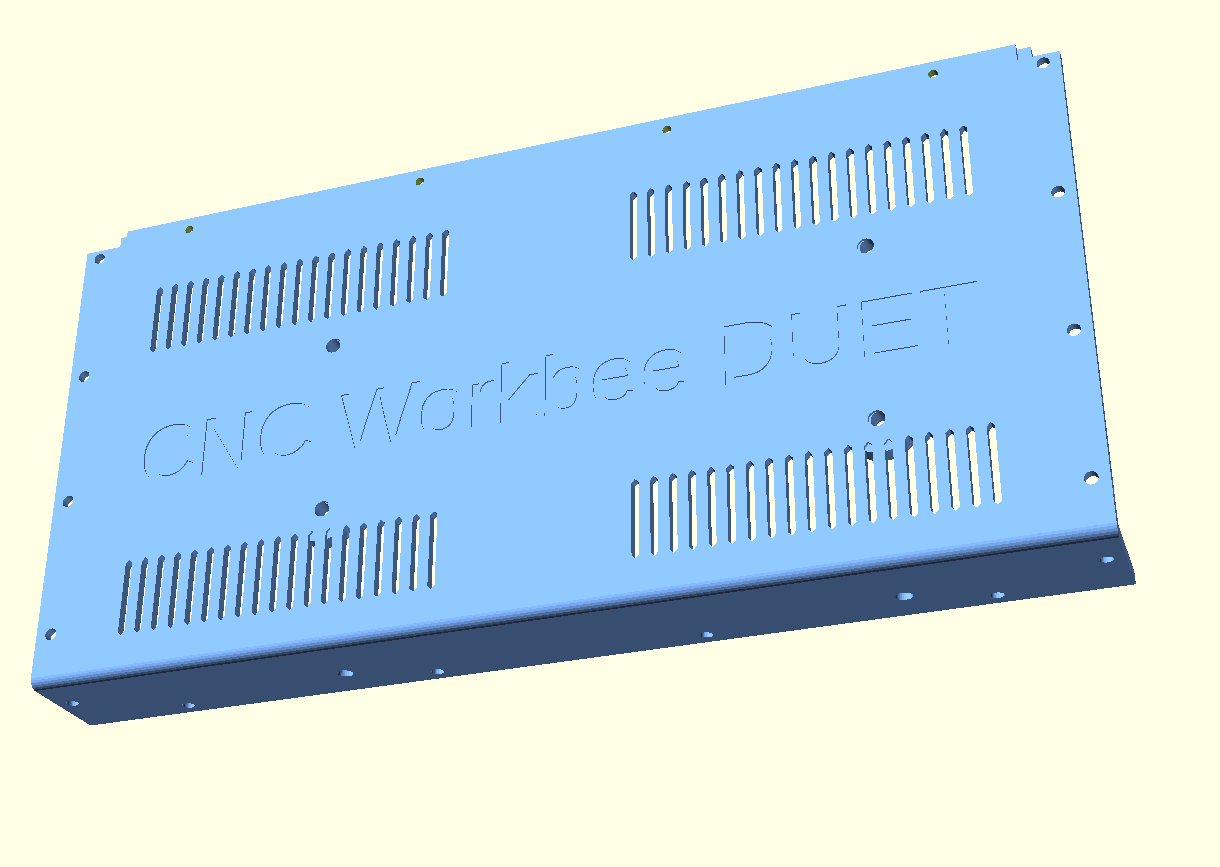
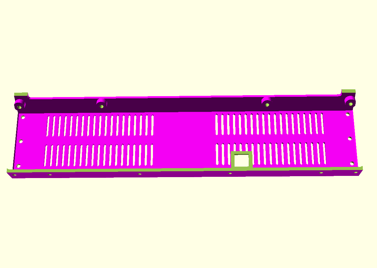
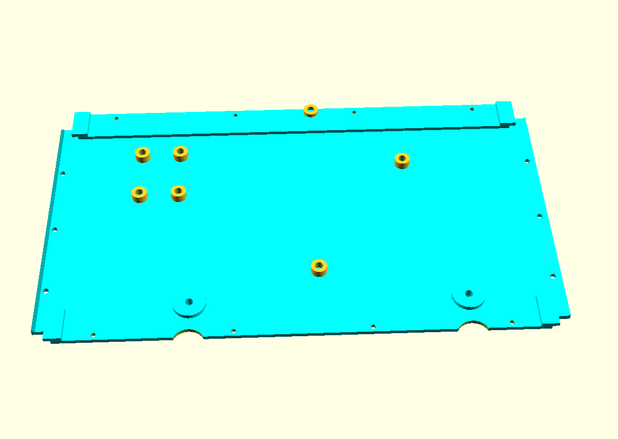
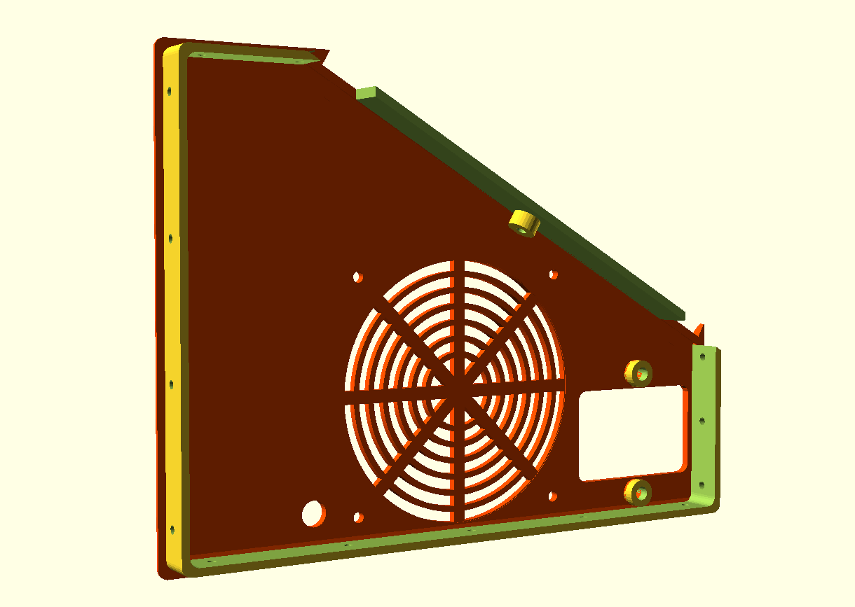
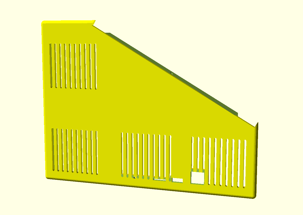
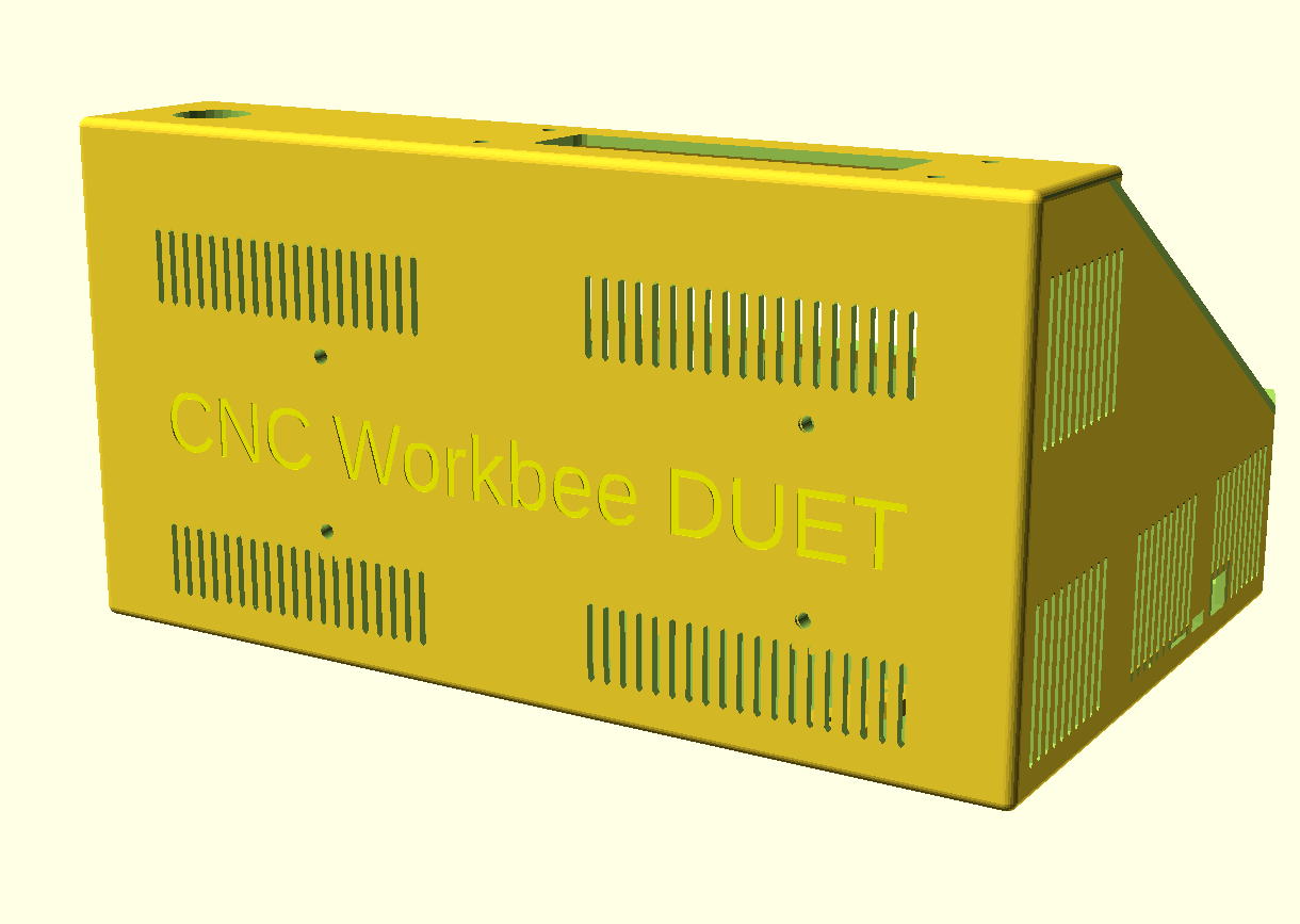
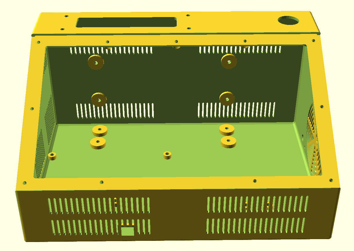
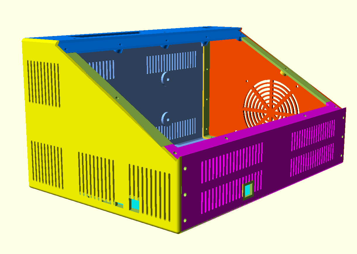
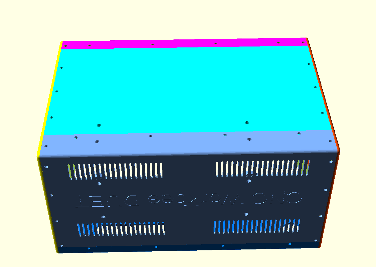
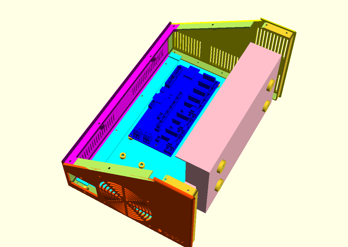
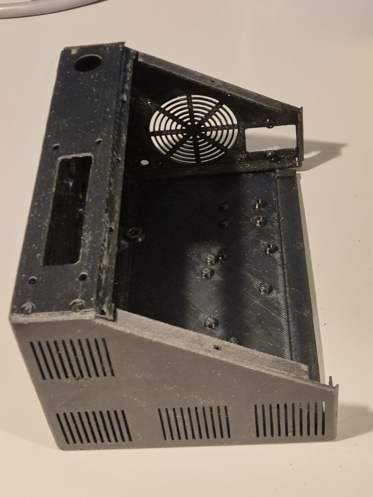
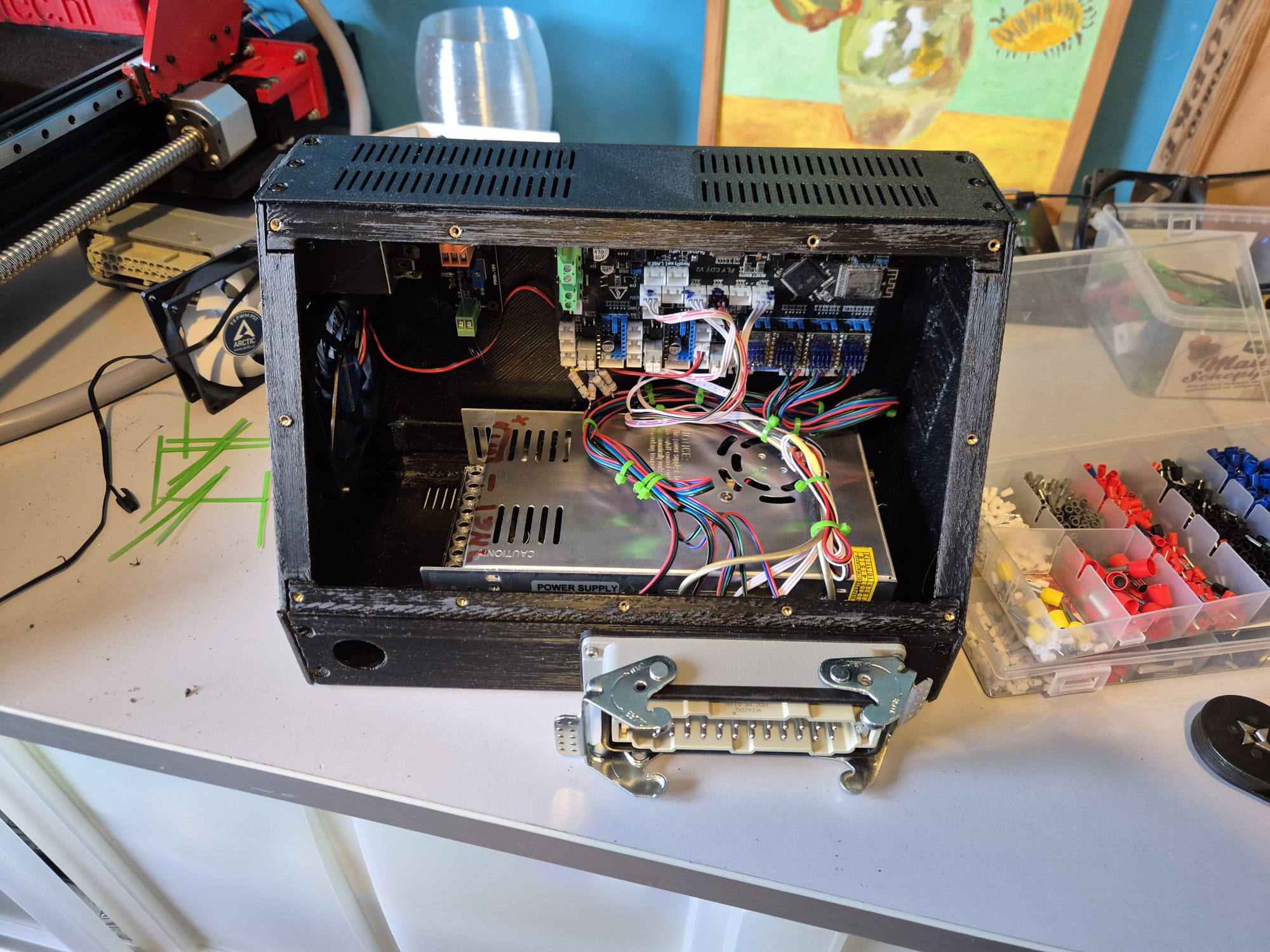
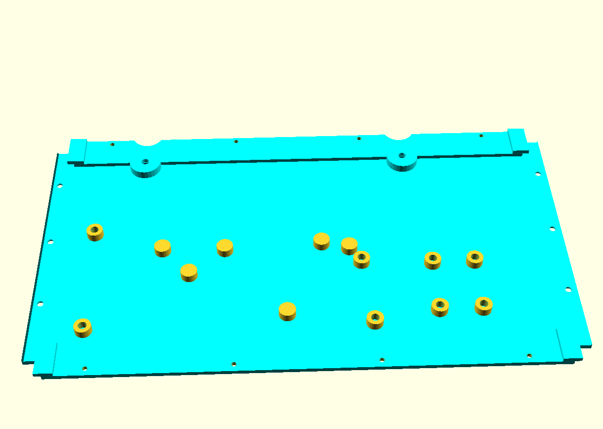
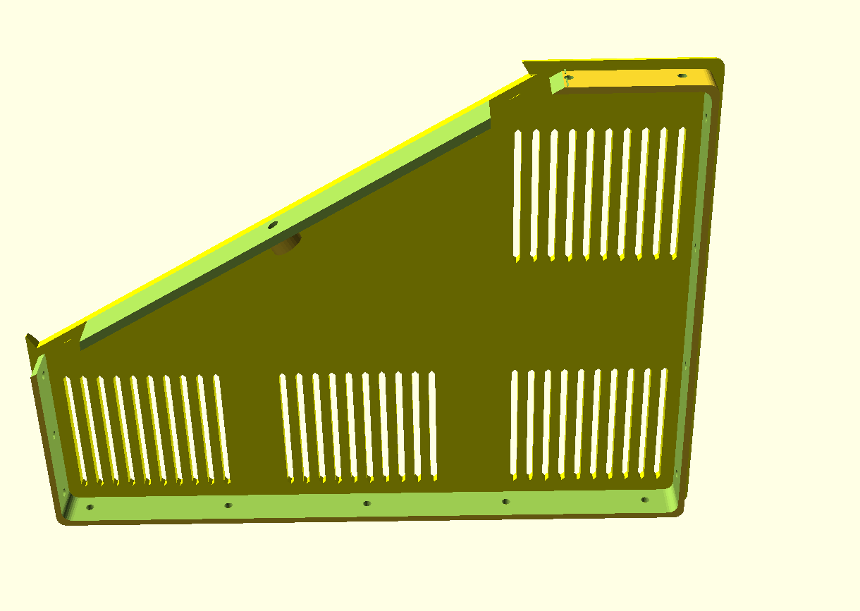
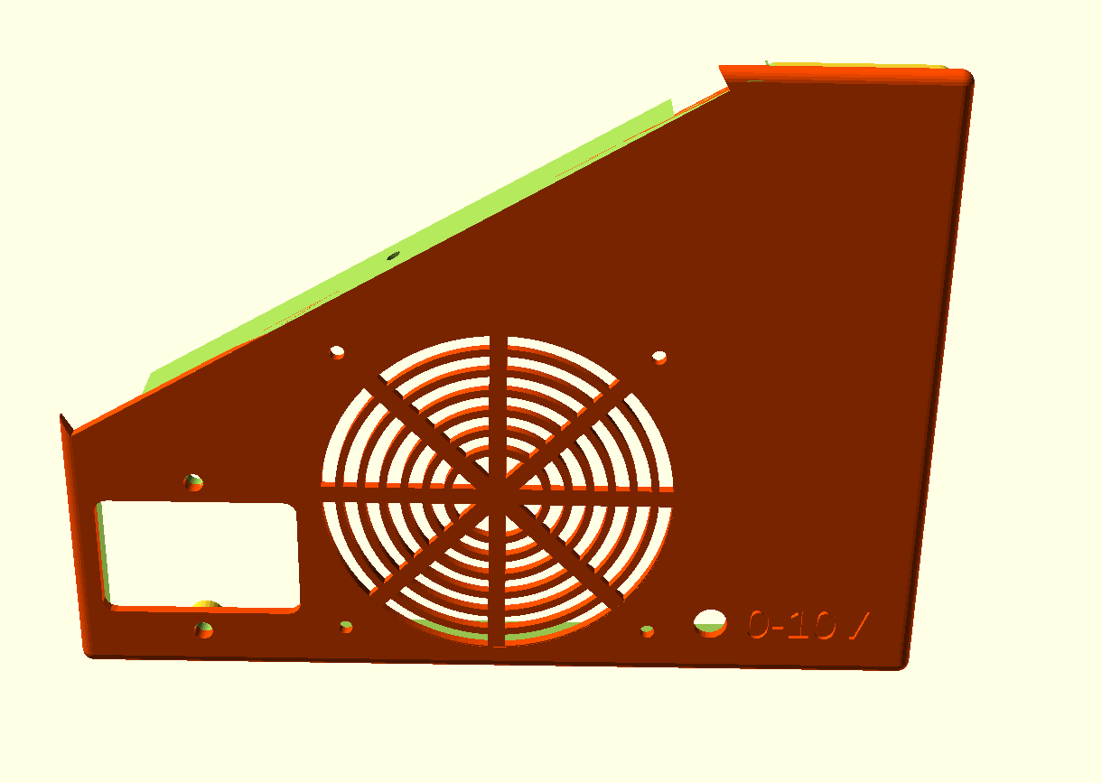
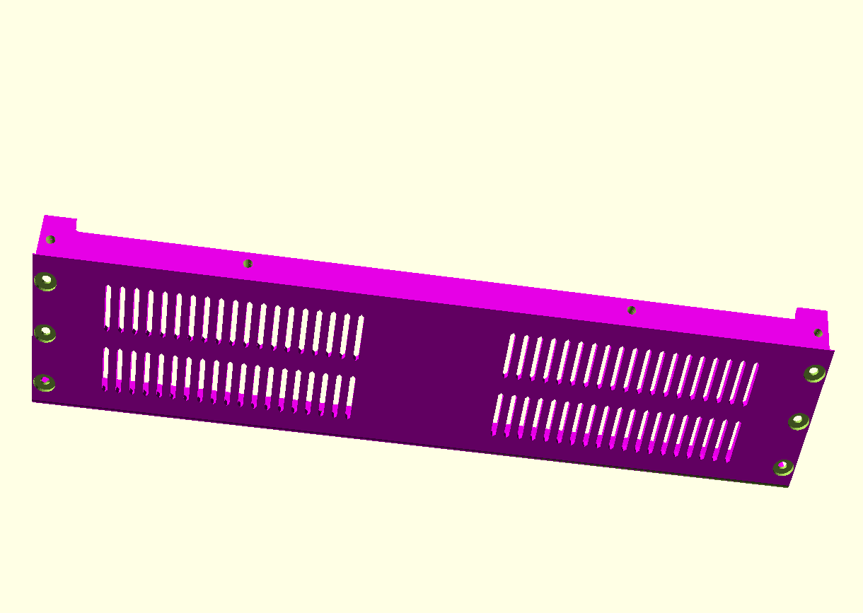
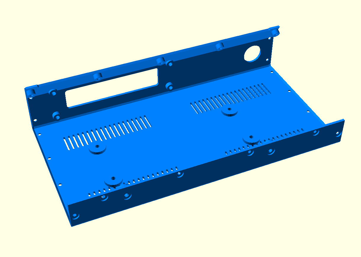
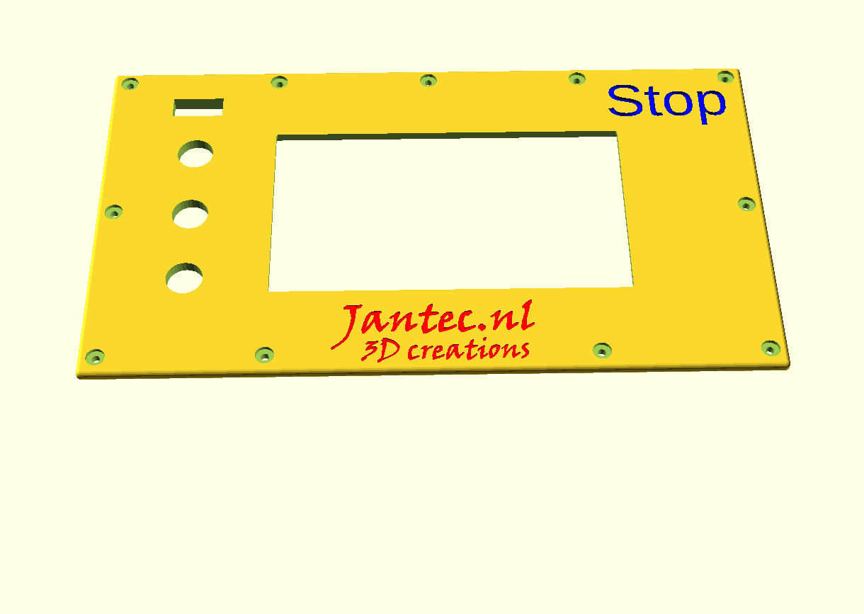
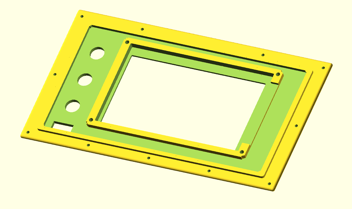
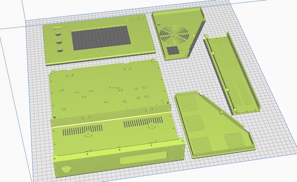
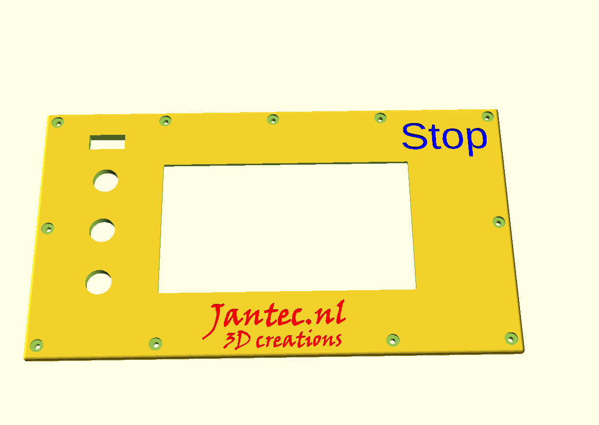
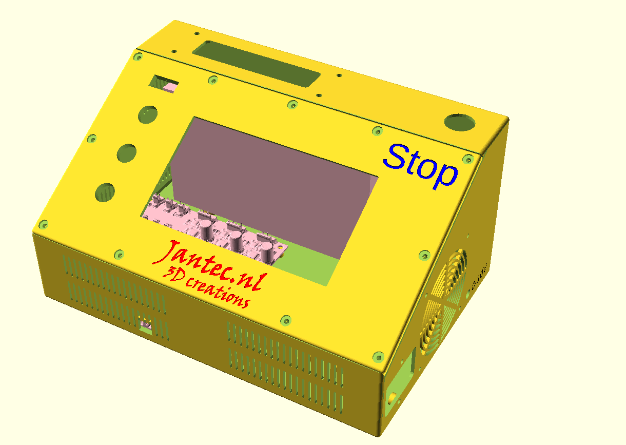
I am building this together as you can see in the below pictures, where the driver boards will be replaced with 6600 pro drivers.

In this post, some other possible choices are presented:
1) Reprap 3.3 & the Duet2wifi. STL’s are made with OpenScad and then converted either online or with Estlcam to Gcode (.nc files). The Gcode is then uploaded via Duet webinterface and run on the local reprap driver board. Not chosen by me beacause it proved impossible to run a gcode stream online from the PC to the USB interface of the Duet2wifi board. It is, however, possible to attach a serial handwheel to the Duet2wifi and manually control the CNC setup. And dual axis squaring is also easily made possible. Actually, the Duet reprap CNC setup is very mature and customizable. I still have this setup as backup and by switching the connectors from the Indymill over, I can easily switch to this setup. Some advantages of this setup are a.o. the webinterface and the ease of having an automatic squaring gantry on the 2 Y axes with individual endstops. I also learned that Estlcam can generate Gcode that I can then send via the webinterface to the Indymill CNC machine which works very well. (I make my designs in Openscad and save this as .STL files. Estlcam can then convert these .stl files to .nc files…, using the machine configuration to get the code properly generated for the Indymill’s dimensions and hardware settings)
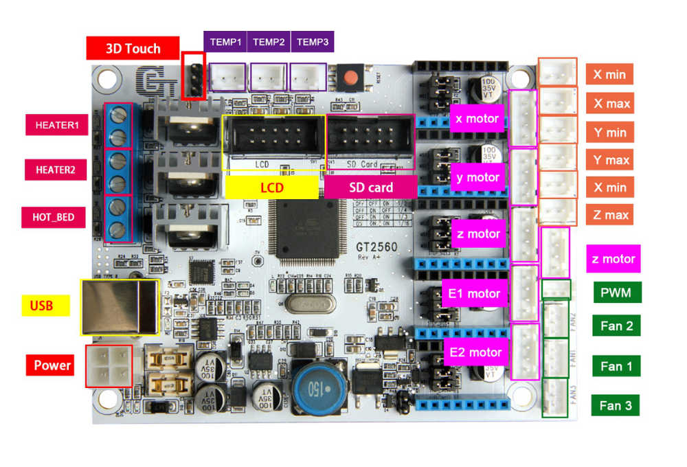
2) GRBL, Estlcam & Openscad, Marlin & GT2560 (A) board; This is also working out of the box and emulates a GRBL driver board.  The main reason to NOT use this is the fact that the GT2560 board just has not got enough pins available onboard for things like a handwheel and other outputs for accessories. The second thing that prevents me from going this way is the fact that it proved impossible to have a functional LCD attached that shows things like position, speed, status et cetera.
3) Mach3, FreeCad & USB CNC ‘barebone’ . This is actually a very solid and reliable solution BUT I could not get it to do any way of squaring my dual Y axis setup. Still investigating this…
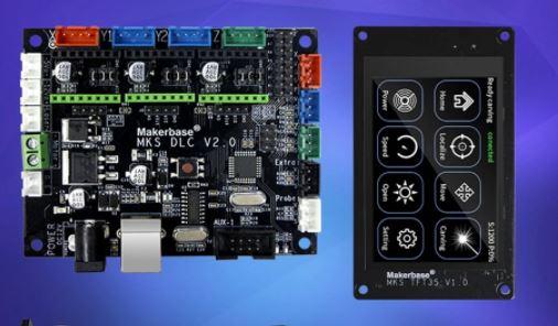
4) GRBL, Estlcam & Openscad & MKS DLCV2.1 board with TFT 3.5 “;  Also for this setup: No option for squaring the dual Y axis setup. But- this is a very neat solution for smaller machines. or larger, if you use external drivers. The nice option of this setup is the 3.5 inch LCD that also comes preconfigured for CNC. I use this for my small 3018 CNC.
5) GRBL, Estlcam& Openscad & Mega2560 & RAMPS 1.6 shield.
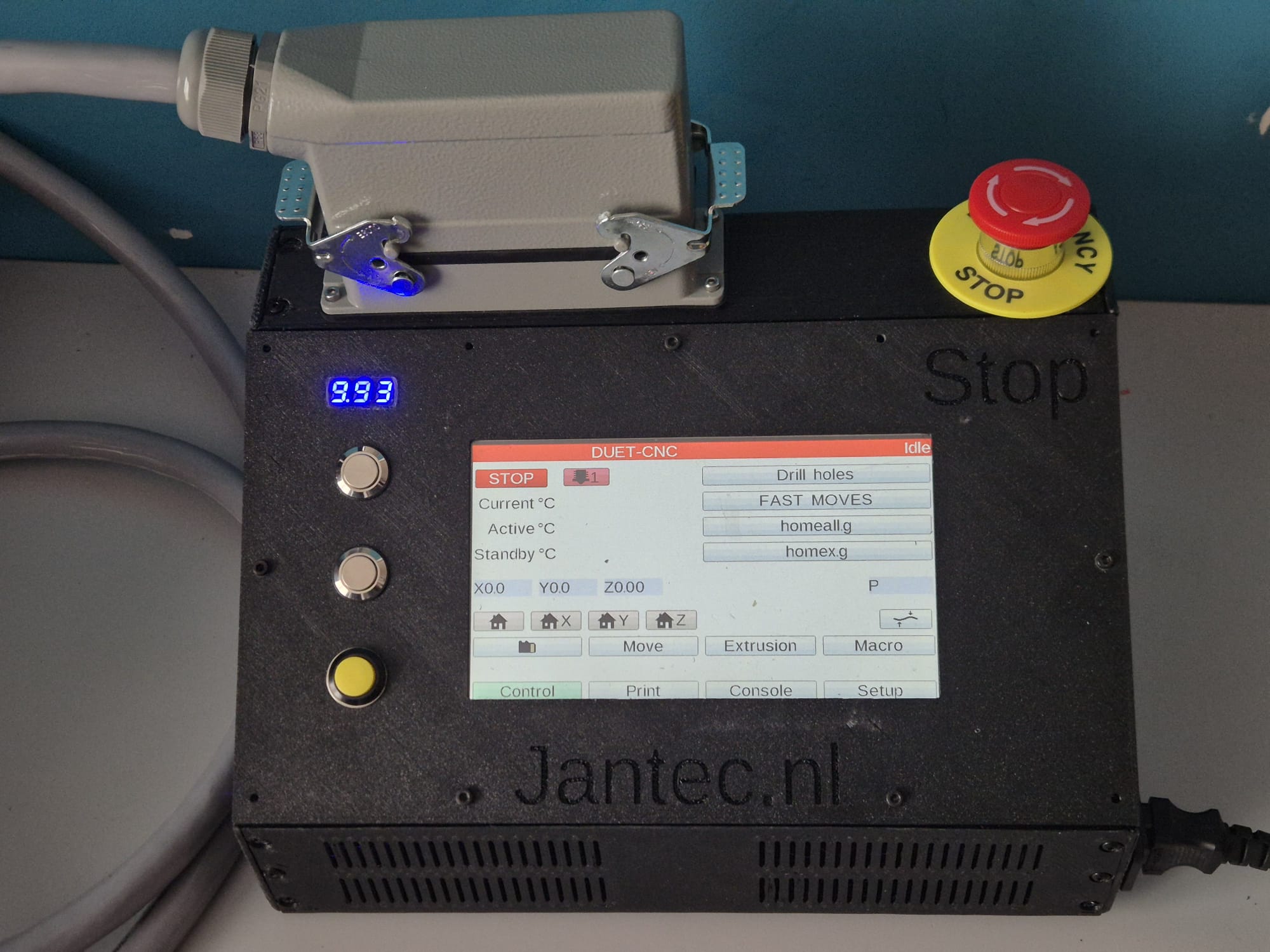
DUET2WIFI clone Mellow FLY-CDY-V2
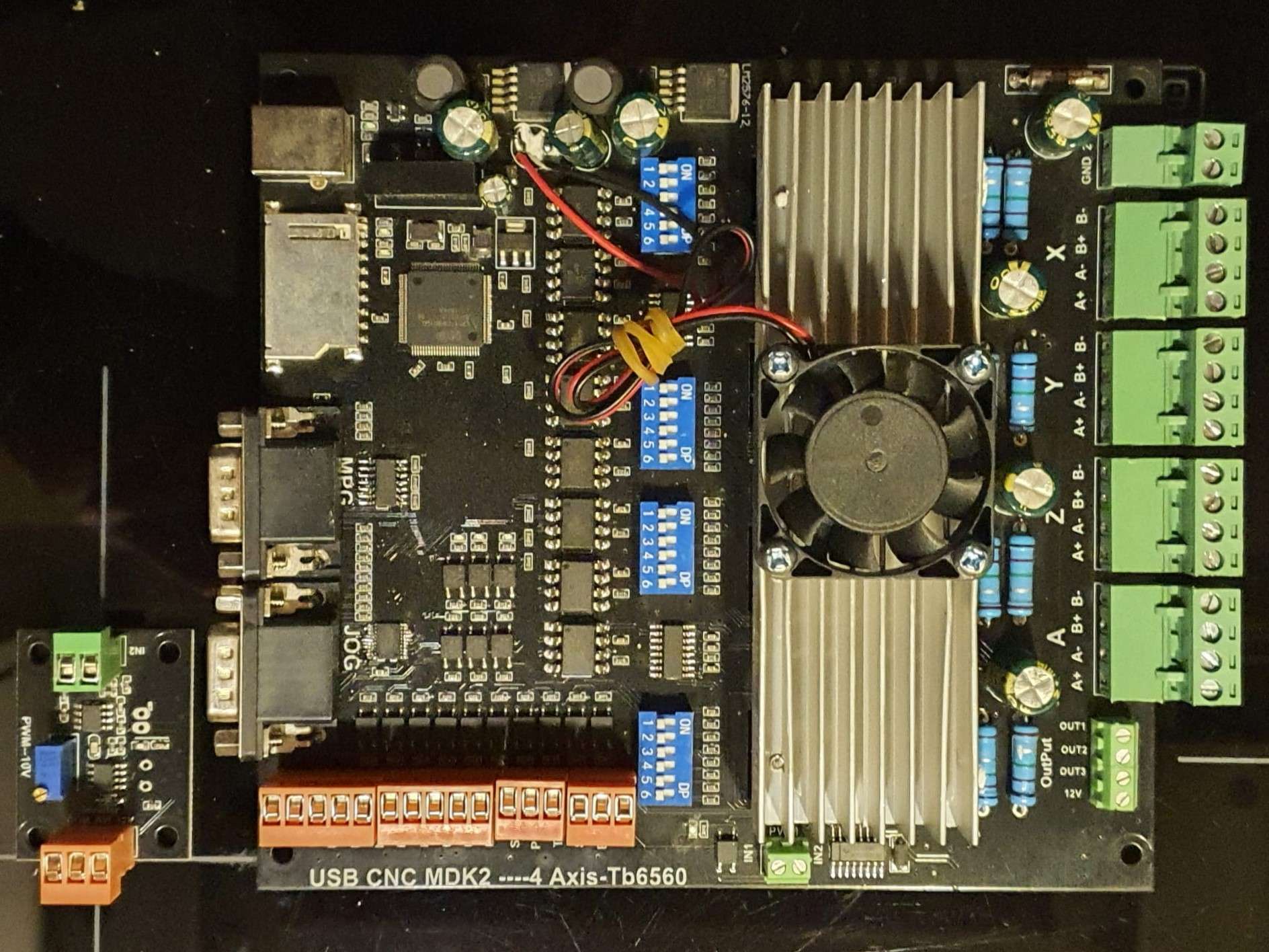
MACH-3 with a generic USB-CNC converter
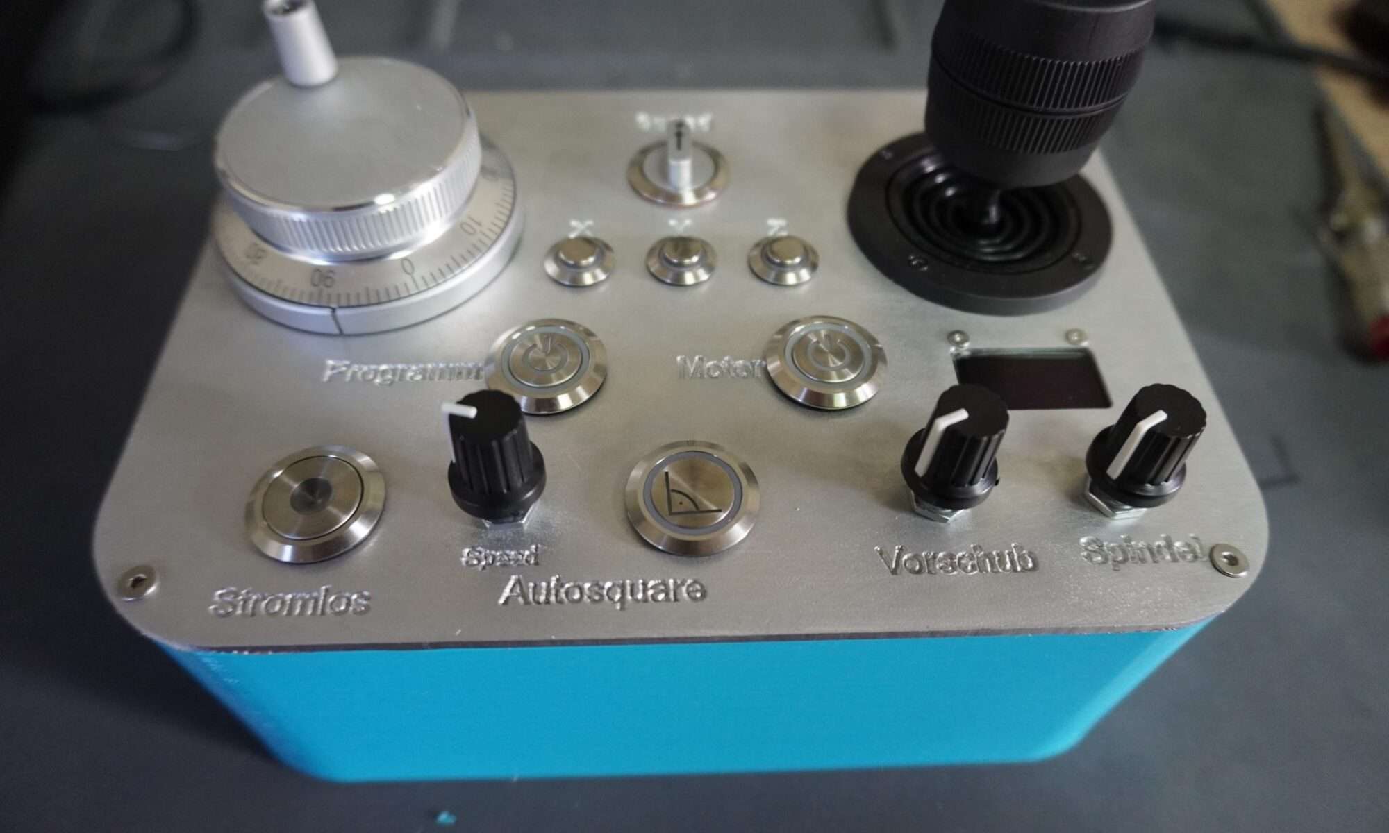
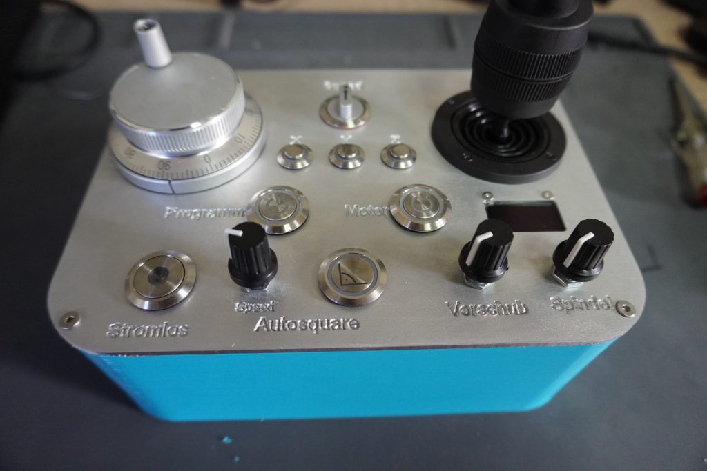
I also have an original USB Mach3 interface with a. o. a handwheel unit. This works very straight forward but needs a PC to keep a stream of Gcode commands running to the USB controller. I am not very fond of this solution since a little mishap will destroy your objects that is being carved. But- this appears to work very well for many people so I have set this up after I had the FLY-CDY-V2 with the reprap 3.3 and the Duet webinterface running, to get to know the differences. I must admit it works straight forward without any problem. I decided to have this setup available next to the GRBL Mega2560/GRBL shield solution. The thing that keeps me from the USB-CNC solution is primarily the fact that this setup cannot auto-square my dual Y axis gantry. The Mega 2560/GRBL shield solution does this squaring very well.
GRBL with MKS-DLCV2.1 and the TFT screen

And- the most in use hobbyist solution: The GRBL boards like the above shown setup from MKS. I have this running on my old 3018 CNC milling machine and it always works well. This particular setup utilizes the preconfigured KMS DLC 2.1 board and the preconfigured MKS TFT for CNC. All is very neat and since the drivers can be adde externally as well as interanlly, it is possible to drive real high currents if you want that. These boards don’t do sensorless homing and usually put the 2 Y steppers in serial. This means that you will never be sure that they are well aligned.
RAMPS shield for Arduino UNO and Mega2560 (and DUE?)
Still to discover: ESP-based CNC board 6-axis on Openbuilds is very promising!


 The main reason to NOT use this is the fact that the GT2560 board just has not got enough pins available onboard for things like a handwheel and other outputs for accessories. The second thing that prevents me from going this way is the fact that it proved impossible to have a functional LCD attached that shows things like position, speed, status et cetera.
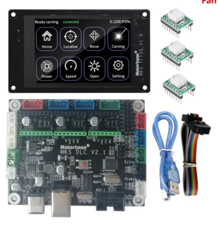 Also for this setup: No option for squaring the dual Y axis setup. But- this is a very neat solution for smaller machines. or larger, if you use external drivers. The nice option of this setup is the 3.5 inch LCD that also comes preconfigured for CNC. I use this for my small 3018 CNC.