

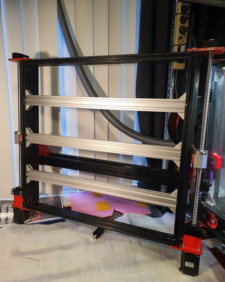
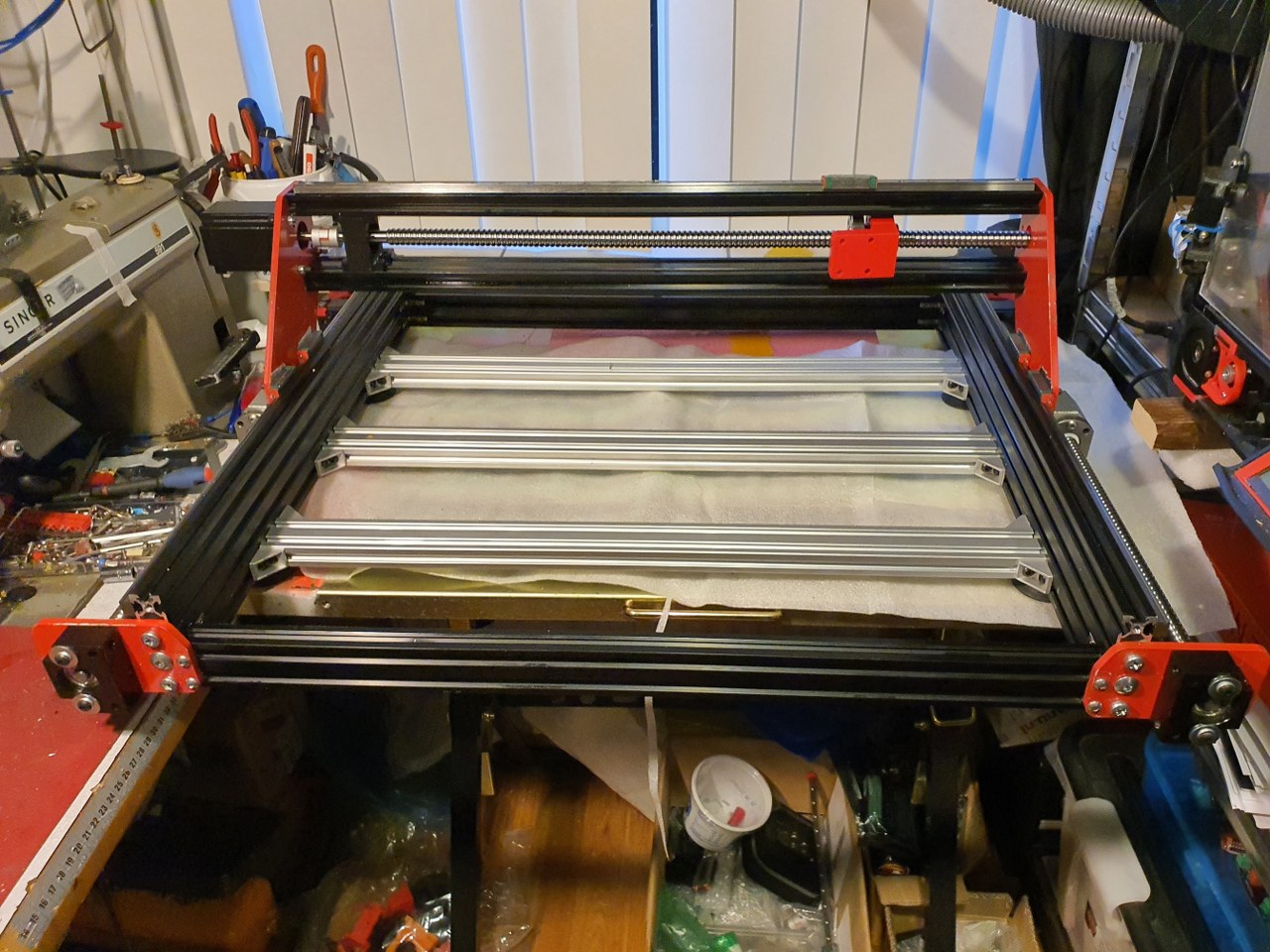
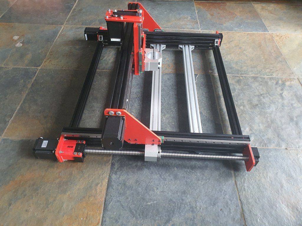
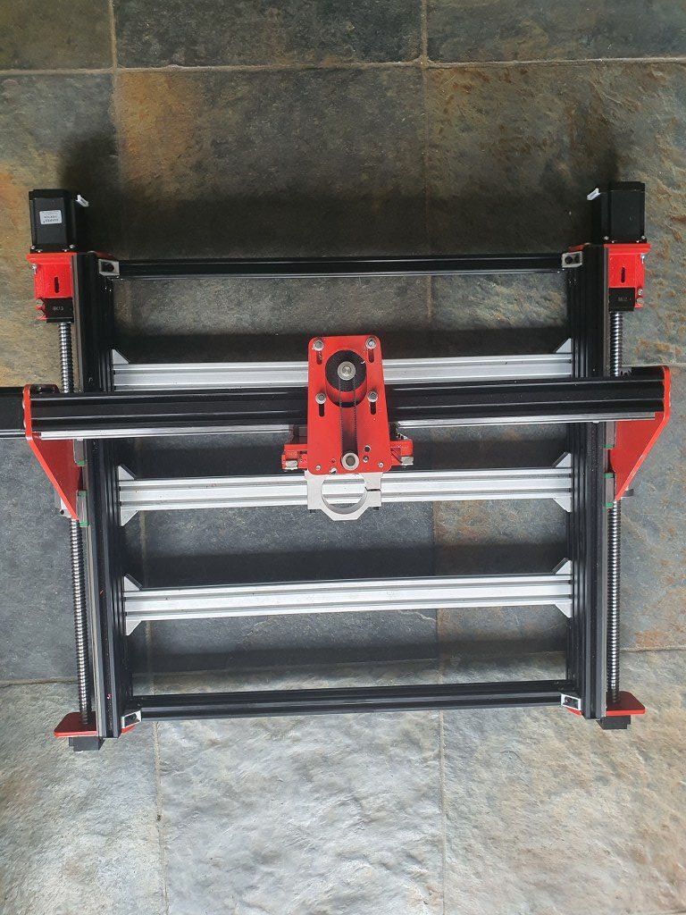
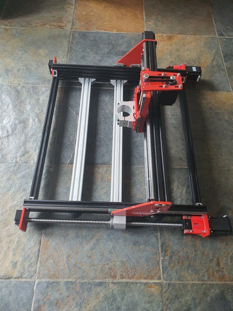
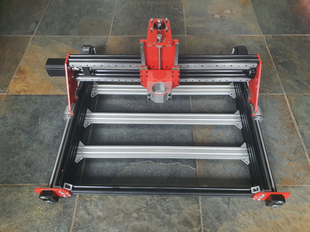
In this post, you can see how I changed the original Indymill to more rigidity by using the original 1605 aluminium nut holders for the 1605 ball bearing screws of the Y axis, and how I made use of the BK12 and BF12 ball bearing blocks instead of the 3d printed parts like in the original build.
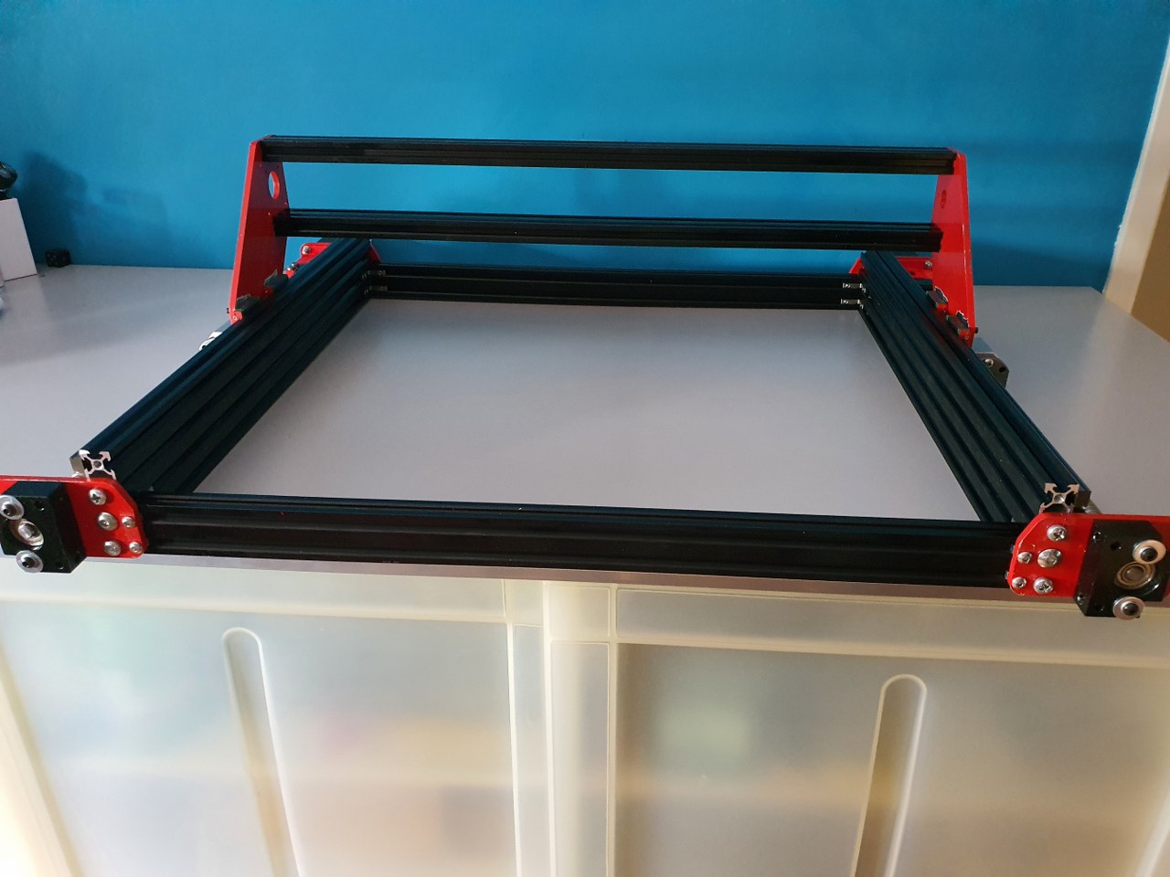
When building the frame, make sure that you do not initially screw anything tight. Follow the steps that apply to any build:
- Make the footprint square by measuring either with a good 90 degrees angled measuring hook OR measure the diagonals against each other and make them alike. Then, tighten all corner screws .
- Re-measure the footprint’s left against right length and also front/rear length. If there is any difference here, a) take everything apart and b) make sure you have equal sizes for your build where this is required. OR, if you have a non-standard build, make sure you build according to specs sizes. The, do 1. again.
- For a lineair rail: use a ruler that is specifically made for your type of rail You can 3d print one or buy two aluminium ones. ALWAYS use at least 2 rulers! With the rulers in place at 20% from left and 20% from the right, after you have installed the rail loosely with the screw in the nuts, tighten the screw a bit but not too stiff.. We will get back to these screws at a later stage.
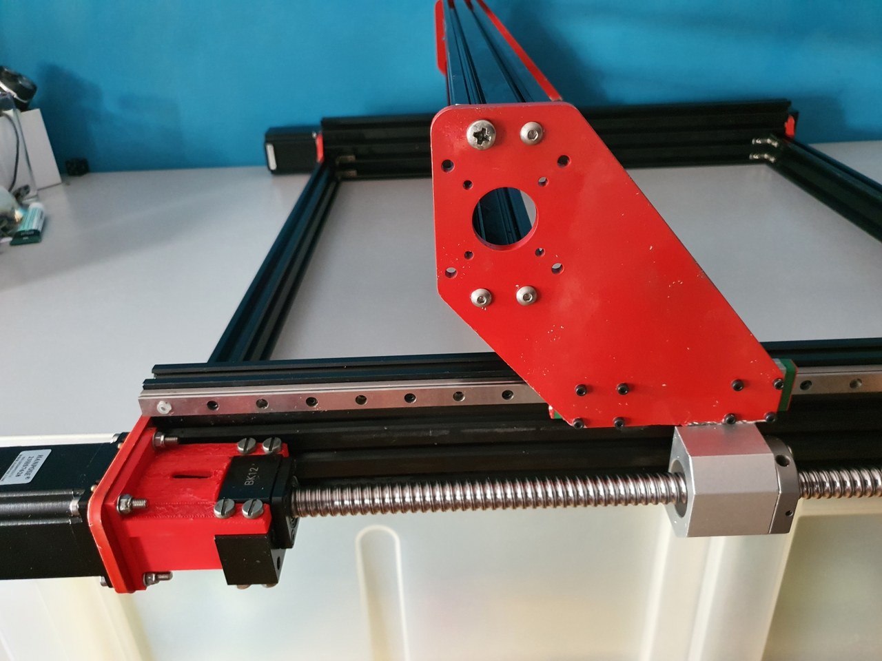
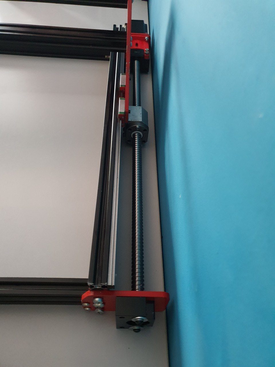
- Put the connecting piece on the motor’s axle (8mm side) and tighten this well. Preferably, use some loctite on the axle but don’t overdo it. Be aware that you need to testfit the BK12 first. make sure that the connecting piece almost touches the BK12’s nut!
- Put the stepper motor and the BK12 connector together, using the 3d printed thin NEMA23 adapter plate between motor and steel plate. Do not yet tighten this too much.
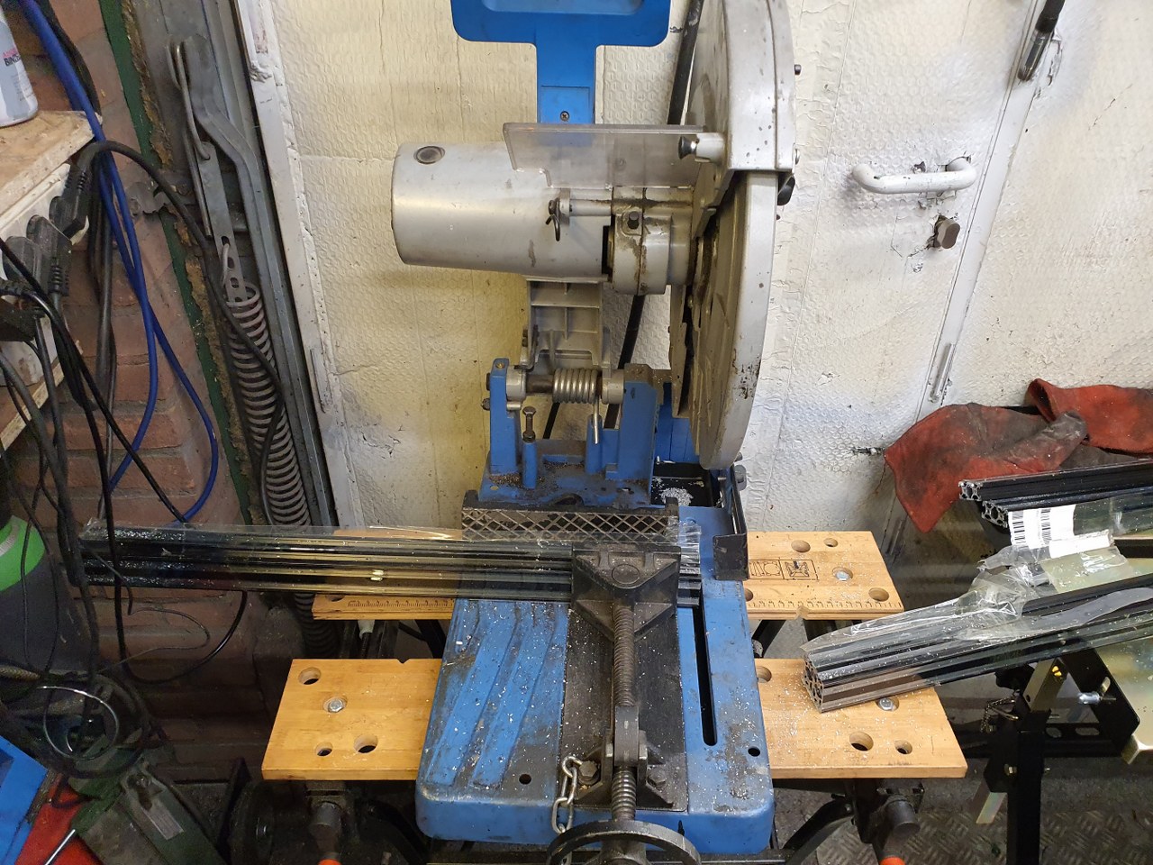
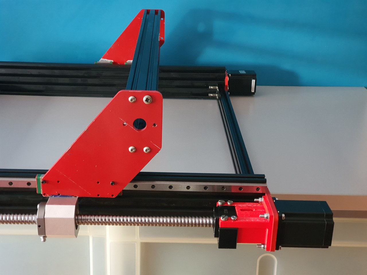
- Make an original aluminium 1605 nut holder block shorter to fit exactly. See the picture.
- Fit the aluminium nut holder block including the entire assembly of the 600 mm long 1605 ball bearing screw on the machine, and superglue the block in the correct position. Let it dry so it won/t come off. Demount verything except the steel sideplate and the glued aluminium nut holder.
- clamp the nut holder to the steel plate with a grip vice, just to make sure it all keeps together.
- Drill 3 new 4mm holes through the steel plate’s lower part , drill through the aluminium block as far as possible. 2 holes on the lower side and 1 just between 2 of the top 3 holes, NOT where the existing hole of the aluminium nut holder block exists.
- Get the nut holder block loose, if it has not already come off.
- Tap M5 in the holes of the nut holder block. You will have come through the big center hole (for the nut) with 2 holes, make sure this gets cleaned up on the inside.
- Drill the new holes in the sideplates with 5.5 mm drill (to give you mounting clearance)
- Place the sideplate on the 2 bearing blocks of the linear rail with 4 outer M3 x8 (or x10) screws.
- Put everything loosely together
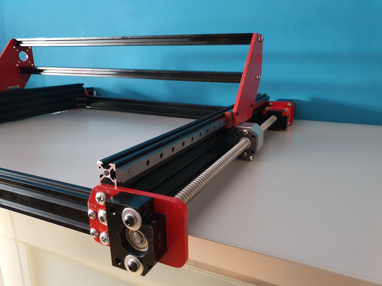
- Mill an end baring block to fit the 1605 ‘s screw end at the front an mount this at the exact center of the small front plate.
- Now, connect your nema 23 engine to a motor steering device so you can test the setup. First, turn the screw by hand and it should run smooth.
- Since you want to have an even height of the side plates, do not alter these unless it needs to be done on both sides equally.
- Your fixation point is the only non-movable position, at the rear of the frame.
- Move the carriage to the rear and now, see if you have slack on the M3 screws of the slide bearings AND on of the 3x M5 screw the rear of the aluminium nut holder. If so, first tighten the M3 screws. Then tighten the M5 screws. If not, loosen ALL of the linear rails screws ans move the rail a little. If this is possible, tighten the M3 screws of the linear rail’s bearing blocks. Then, try to get as much clearance on the linear rail’s movement up/down as you can and tighten the 3x M5 screws of the nut holder block.
- Now, tighten 1 screw only of the linear rail, at the position above the nut holder.
- Move the carriage entirely forward position.
- Tighten the linear rail’s M3 screw that is exactly in position above the nut holder (of the ball bearing screw)
- Now, tighten all screws of the linear rail.
- You’re done!
- Check the other side and if the linear rail’s height differs from the other side, the only thing to do is to start over again, where your slack is in the 5.5 mm holes of the steel plate’s screw holes for the nut block. If you play with this, and then adjust the linear rail’s height, you can get it all even. At least’eventually I got mine right but it took some time. Have fun!
Things to bear in mind: You don’t want anything out of parallel like a linear rail that is uneven to the aluminium profile on which it is mounted or a ball bearing screw that gets under tension. There is also another way to see what is happening while you are tweaking the hardware/frame: take the front bearing off and see what happens to the end of your ball bearing screw in the hole up front when you move the carriage. It can tell you much about what is happening… It should always stay perfectly centered but I’ve seen it up, down and all other directions.. -)
And- I must say, this build goes quite well. The materials are OK, and the guideline from the build description was very good. Although I never use it anymore. The build is quite self-explanatory once you start building the Indymill CNC machine. I also cahnged quite some parts, and made alterations where I felt this would improve the machine to fit my purpose better.