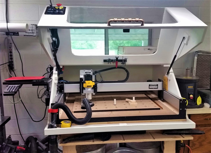
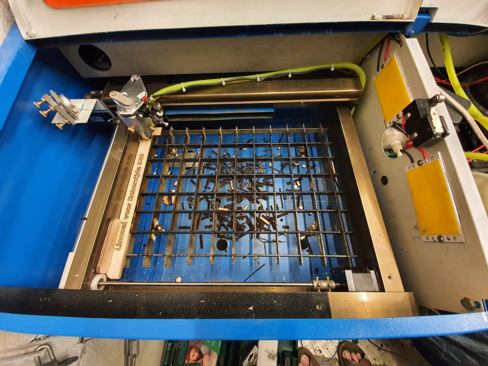
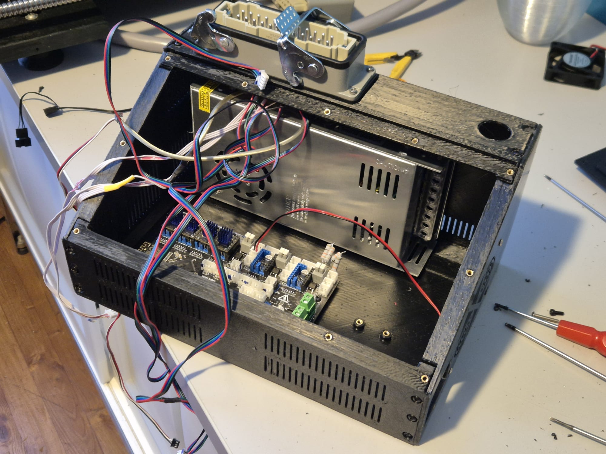
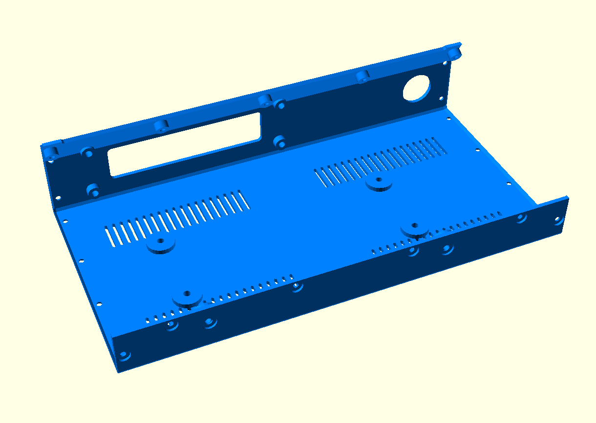
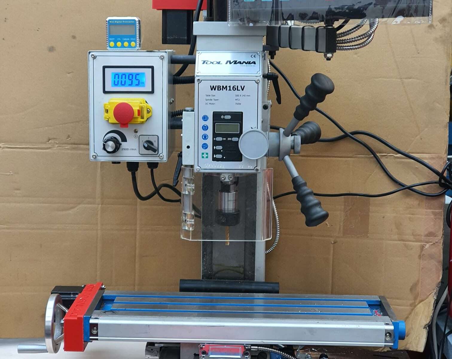
To get the Indymill running, at first I chose to use the Duet2wifi and reprap3 as base.
Since I am very familiar with Reprap and with the Duet, I want to try this anyway.
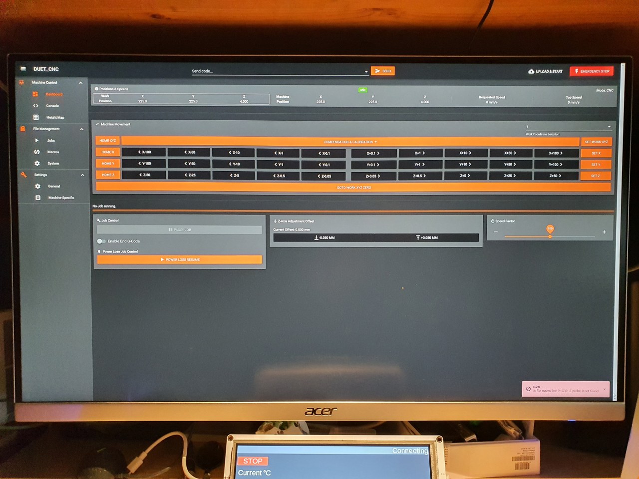
In the end, if it is all installed I need to have software to design and get a file with Gcode and this will be sent to the Duet2wifi controller via wifi, using the Duet’s webinterface that is been developed for CNC in Beta (DWC for CNC).
I currently use Openscad for designing, export as .STL and then make a .nc file for the CNC machine from this with Estlcam.
In Estlcam you can make the machine-specific settings like where the center is, how to set Z=0 et cetera.
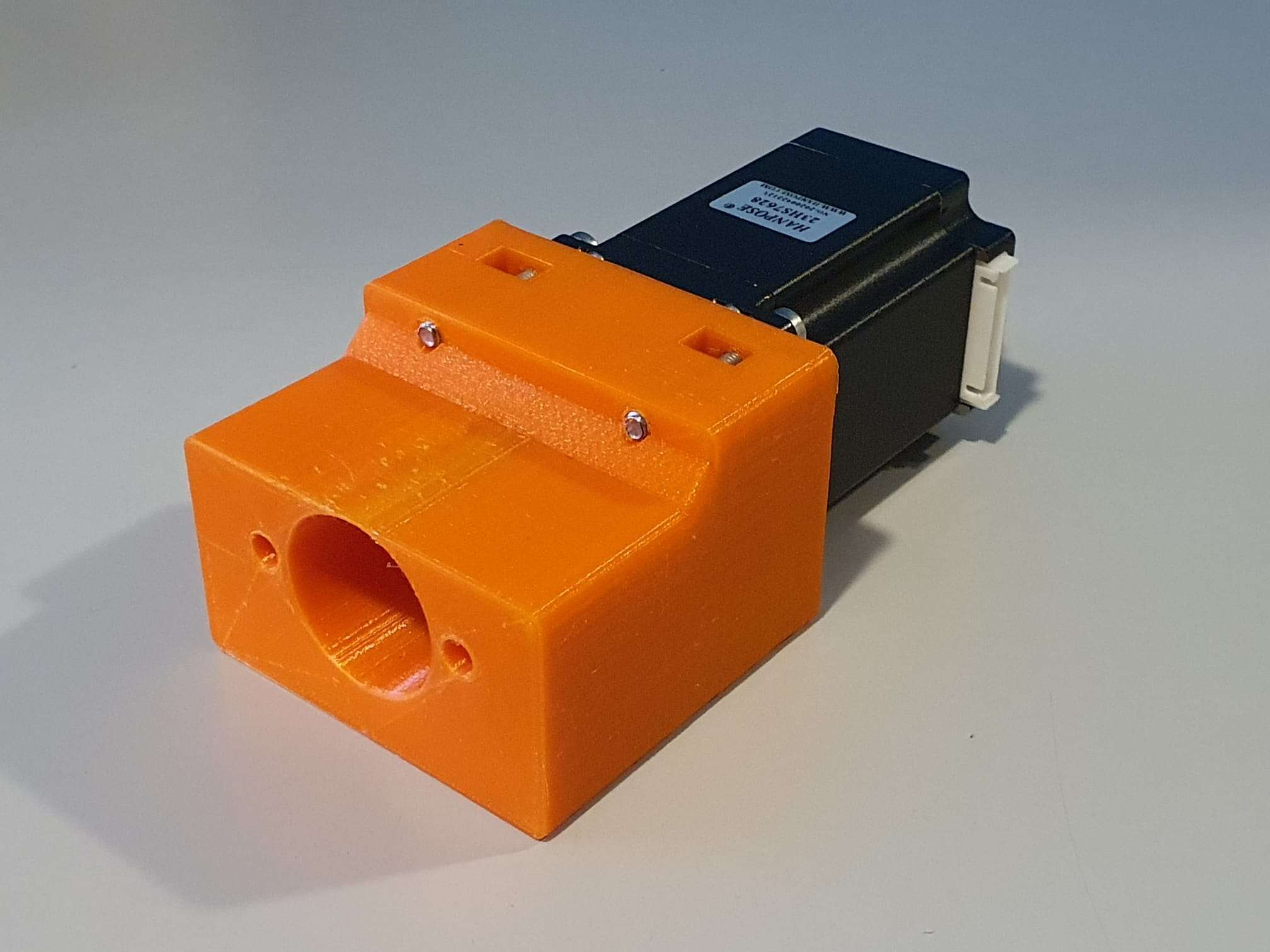
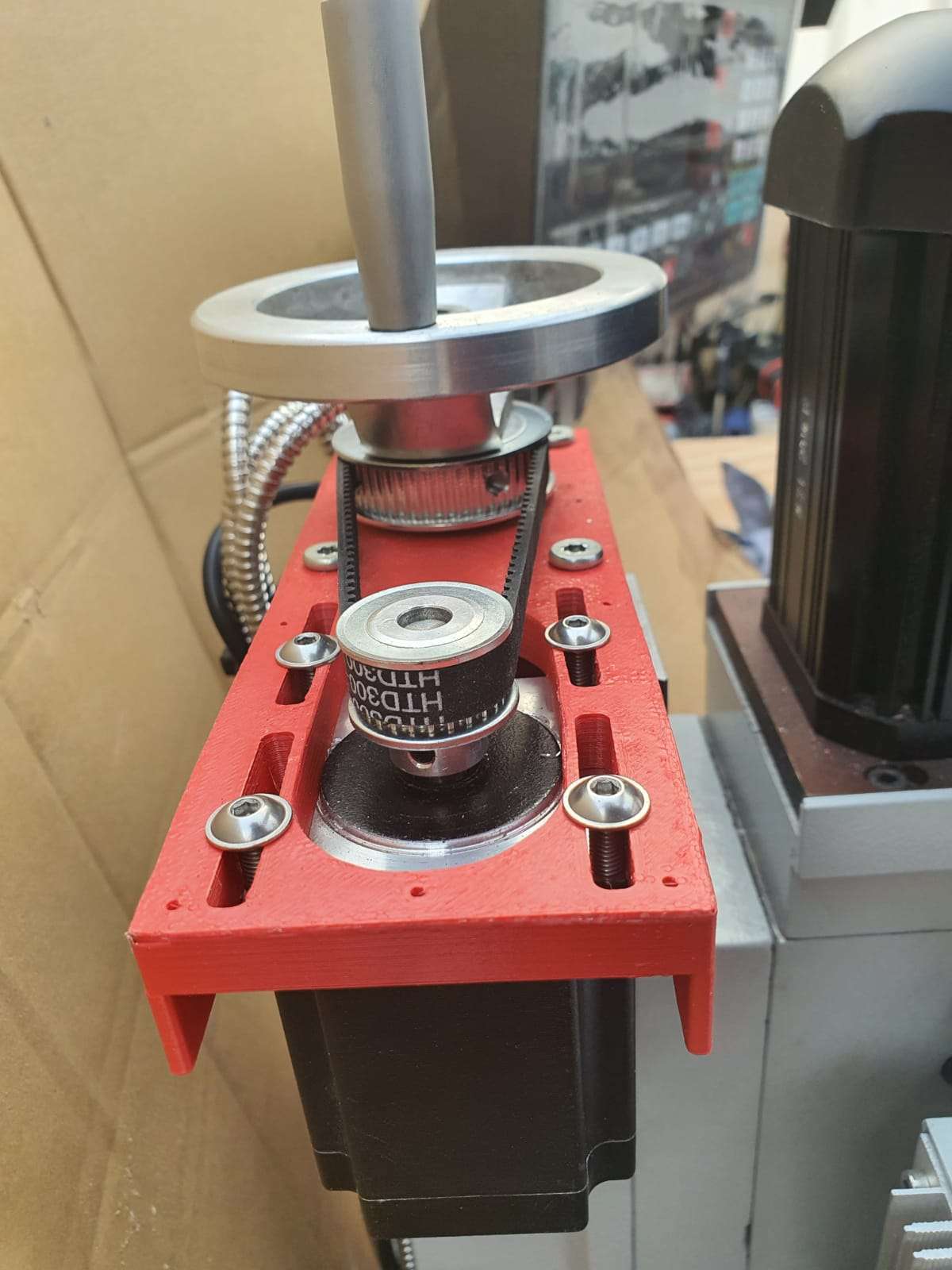
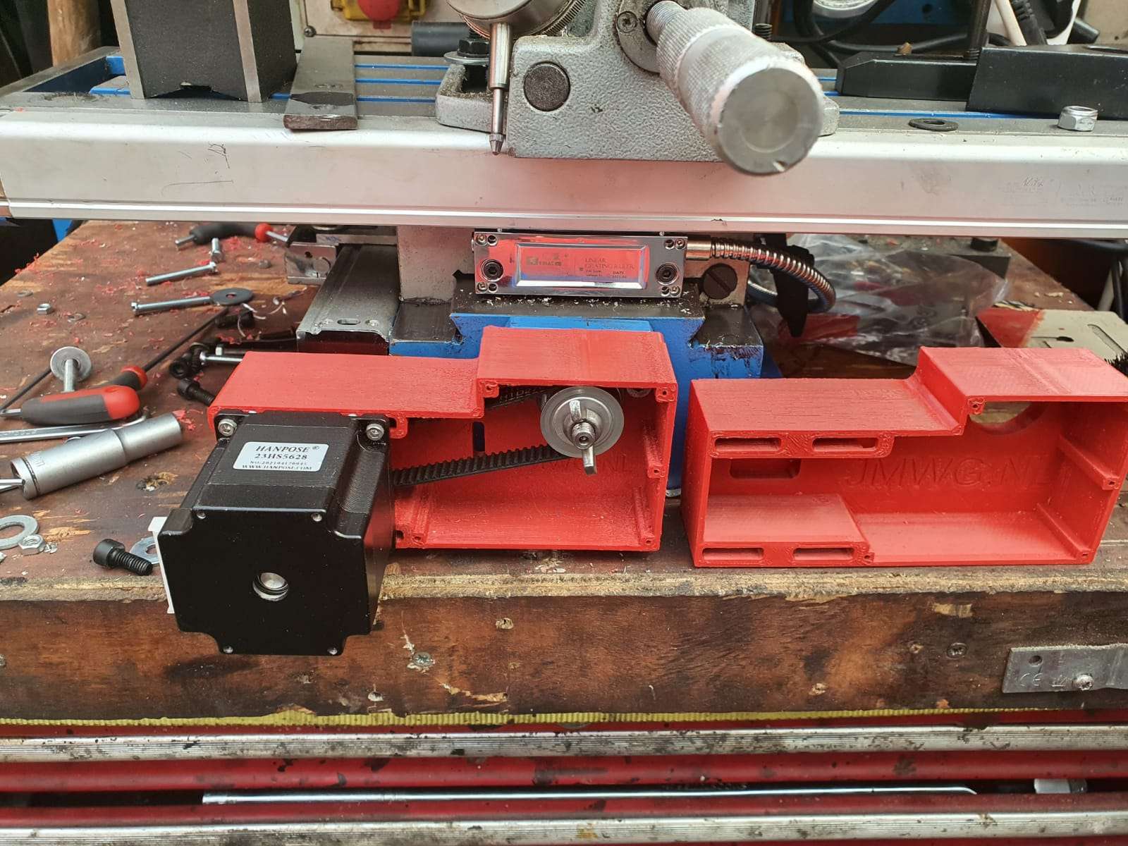
The Duet2wifi is my favourite solution because I can if so desired use sensorless homing on any axis. And- because I need to home 2 independant Y axis and I have a lot of experience in making this work I first went for this solution. For my settings with sensorless homing please see THIS POST
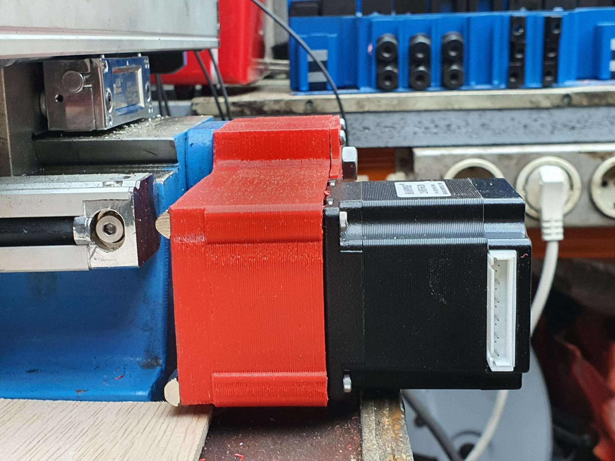
When you get a good enclosure for the Duet2wifi, use 24 Volt PSU and good driver cooling blocks, you can push the Amps to over 2 Amp continuously. Works well with my Nema23 steppers. 2.5 Amps is max but we don’t want that, I found that 1.8 Amps works very well and creates enough torque for the Indymill.
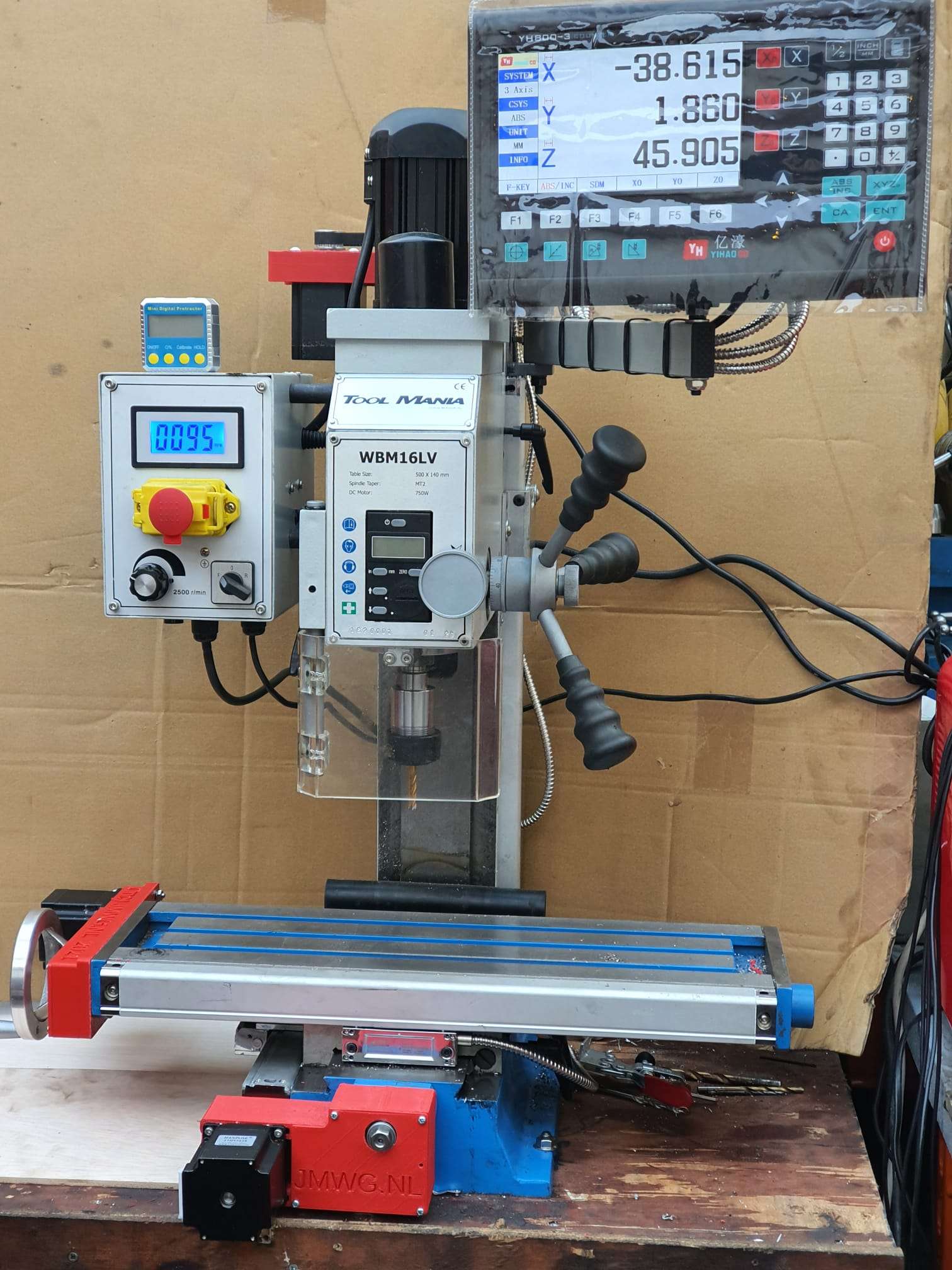
After having the Indymill work with sensorless homing I rebuilt all to be used with endstops instead for better stability and compatibility with my other driver board setups. I do want to use the Indymill with several driver setups, and for this setup to be exchangeable, I need the endstops anyhow.


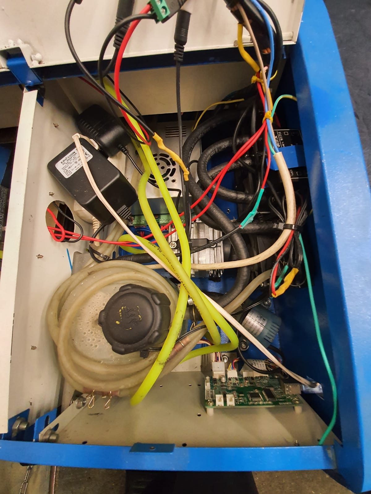
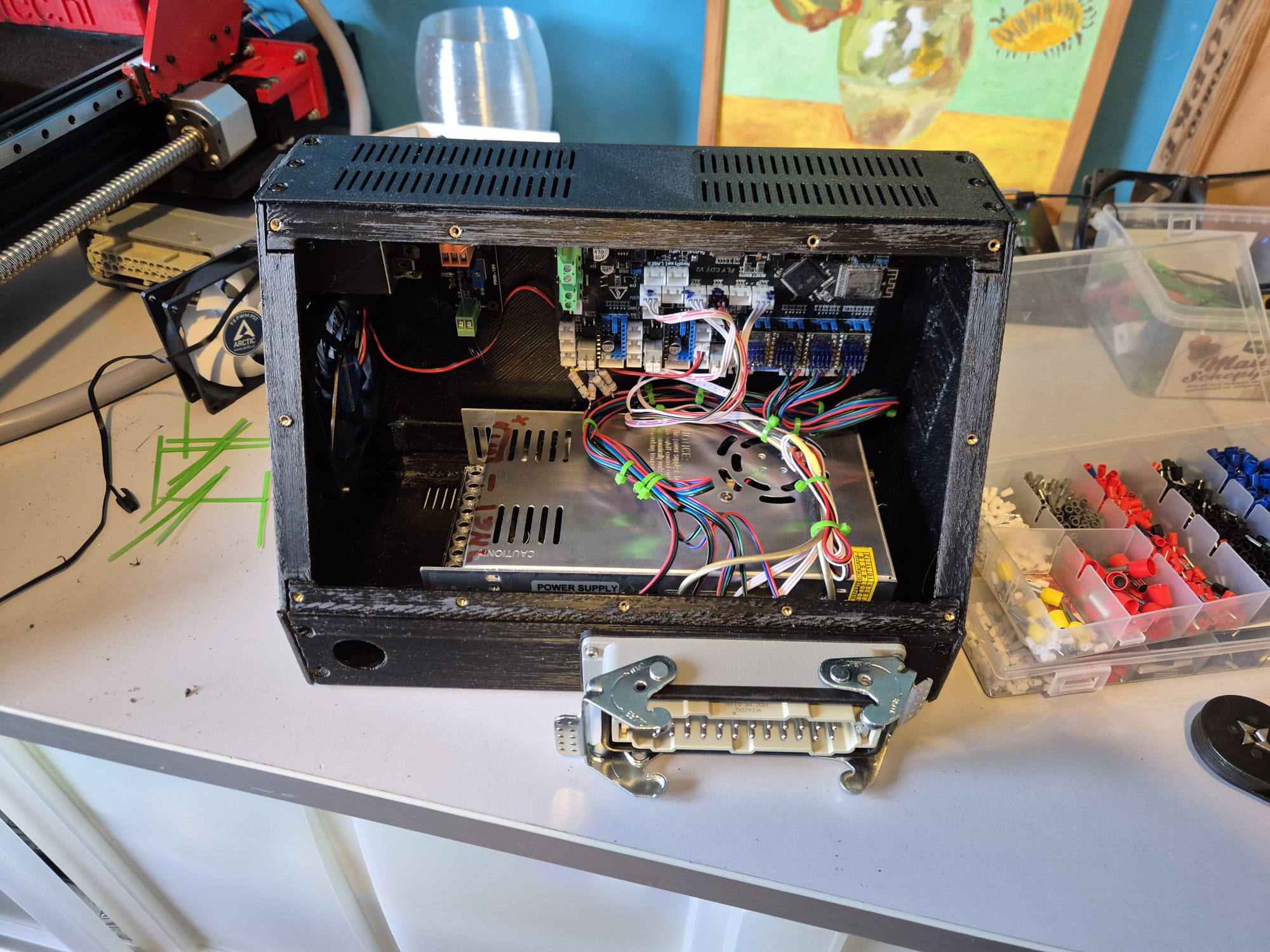
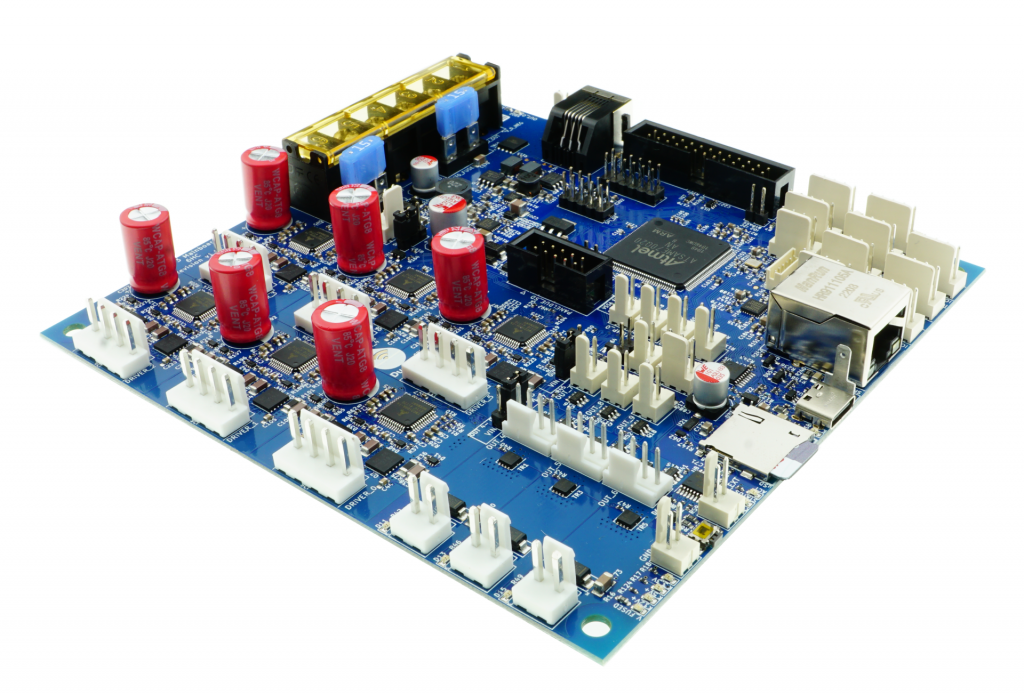
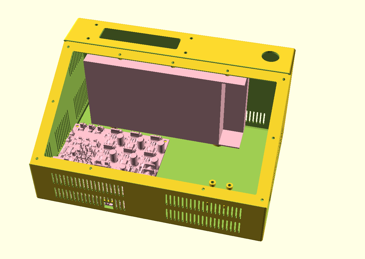
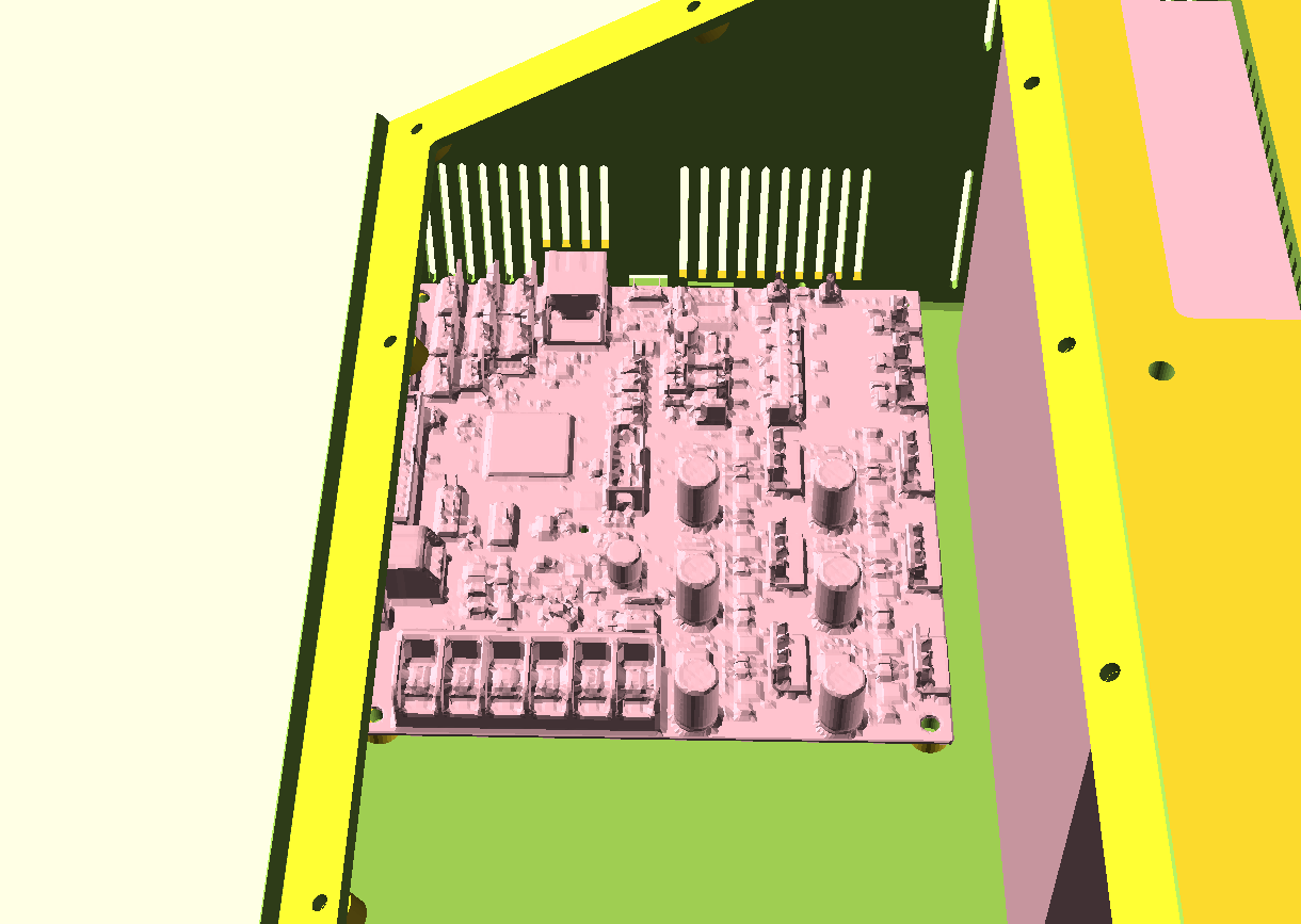
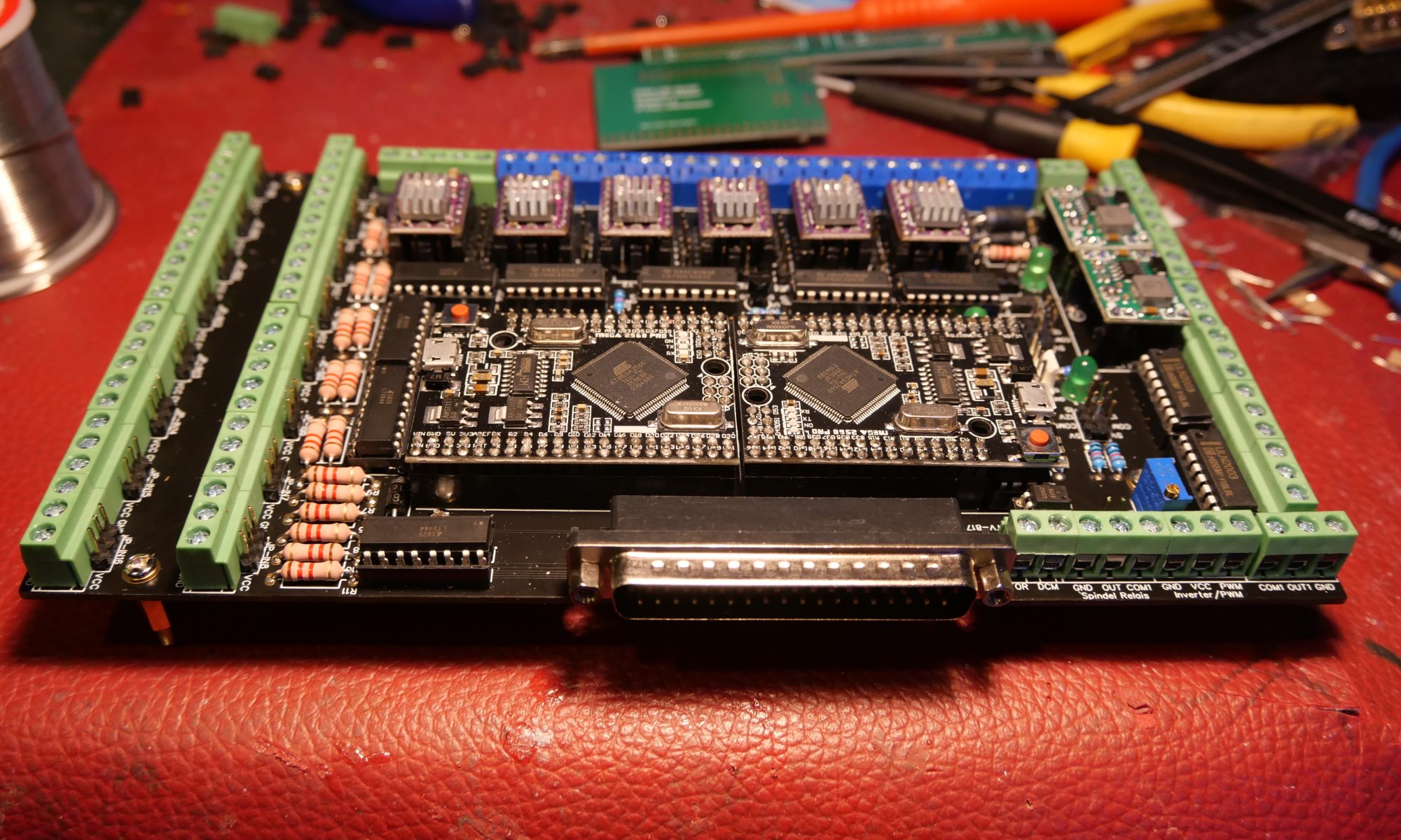
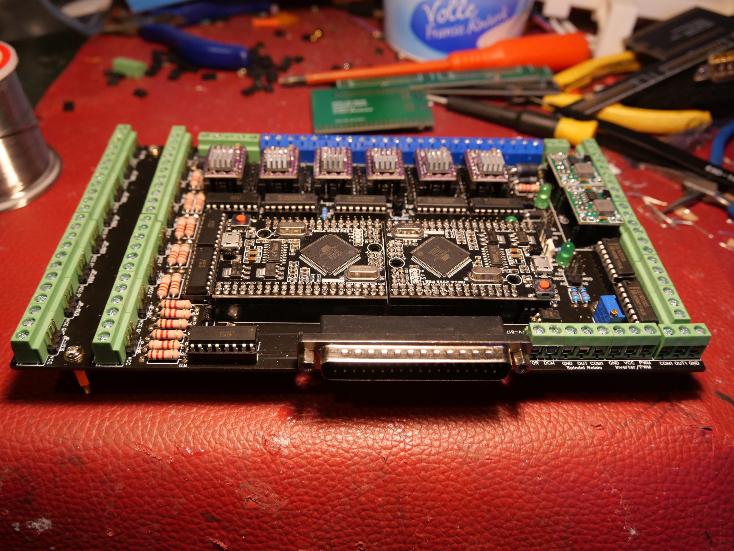
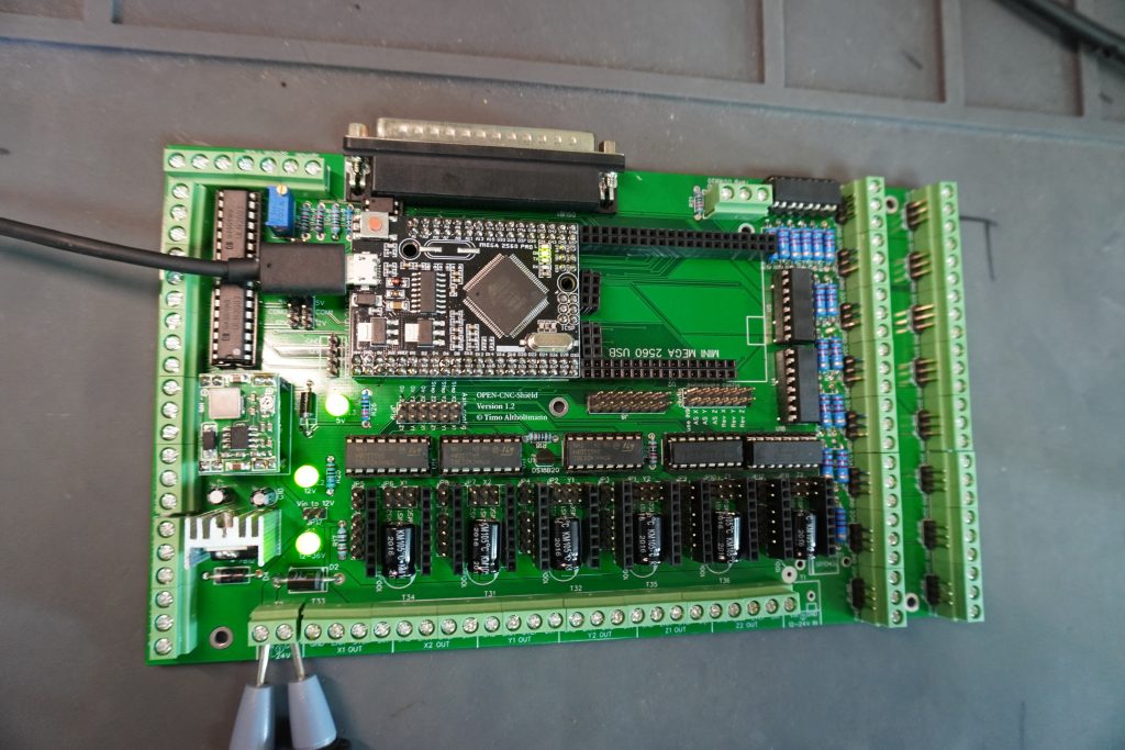
I am currently using reprap boards from Mellow, since they use the raprap firmware that is ported to the STM core that the Mellow boards use.
On top of this, on the esp you can mount the Duet’s DWC software and thus also the DWC CNC software.
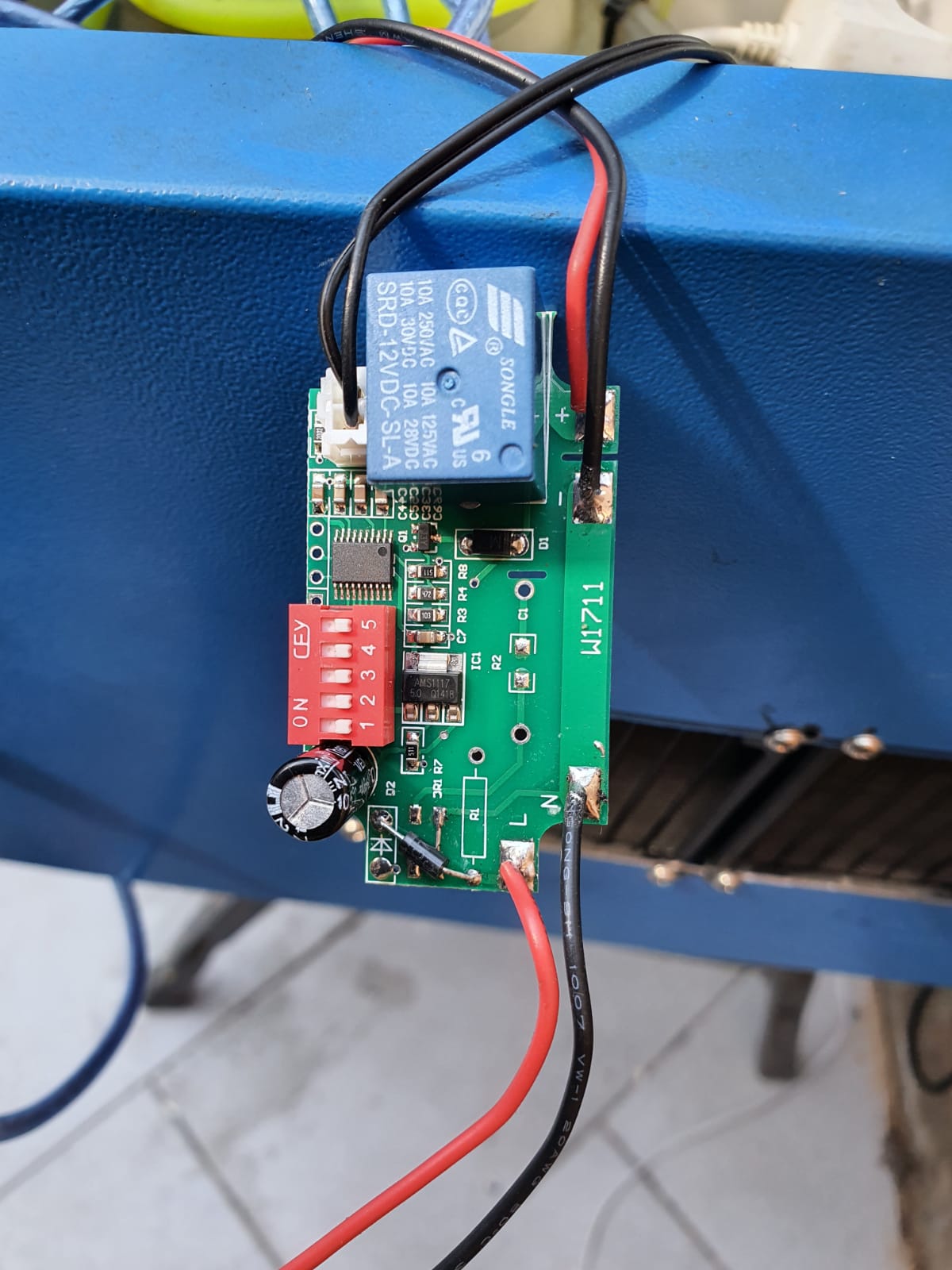
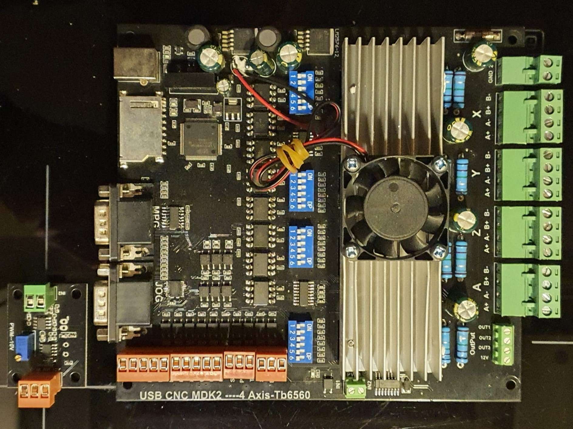
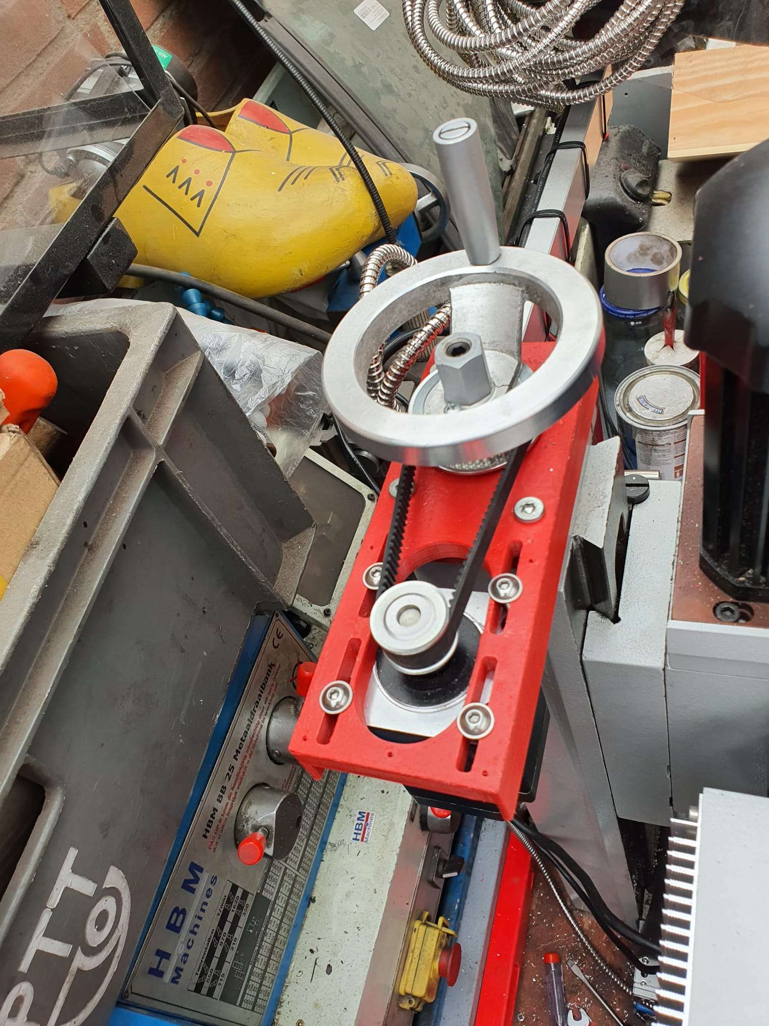
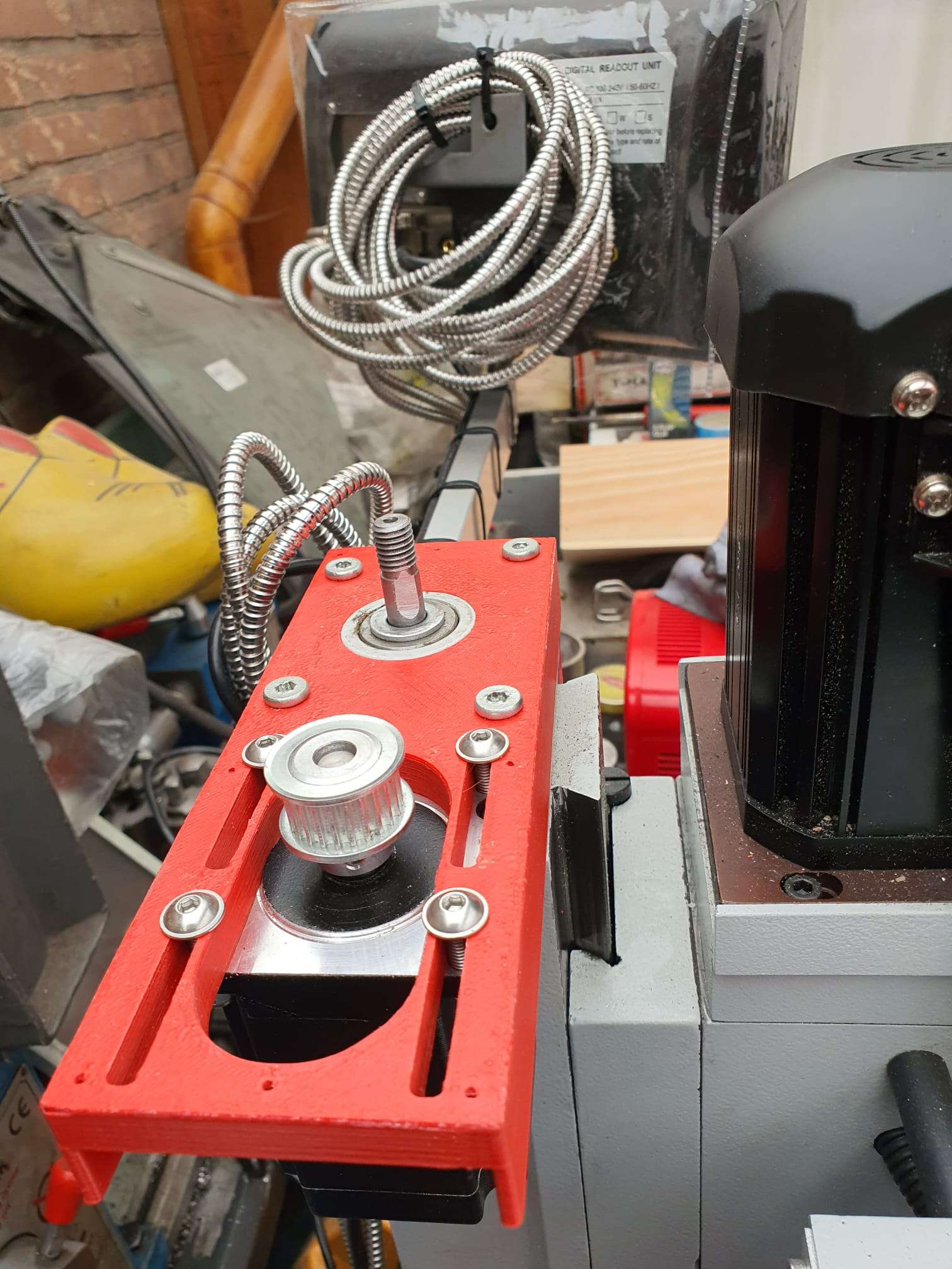
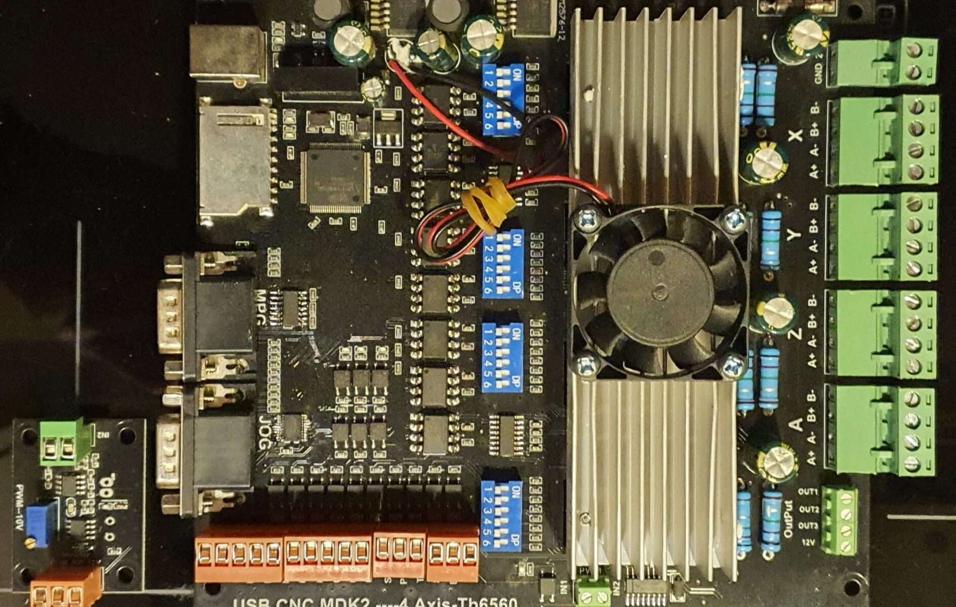
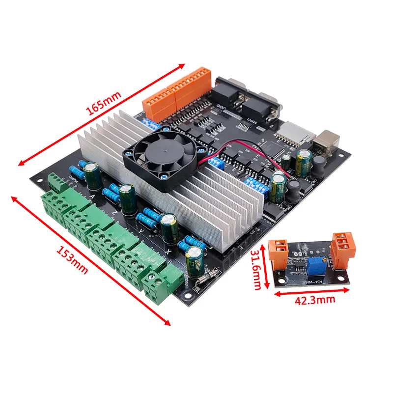
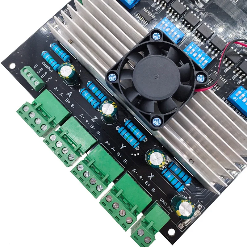
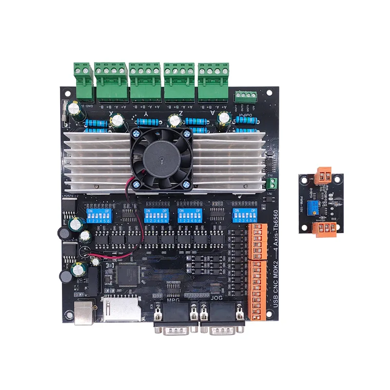
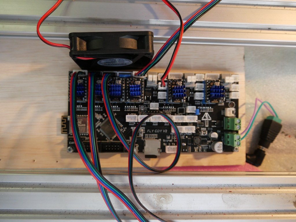
I have this currently running on the Indymill with a FLY-CDY V2 board and TMC2209 drivers.
The nice thing about these Chinese boards is, that you can mount any driver you like, and this means that external drivers is also possible.
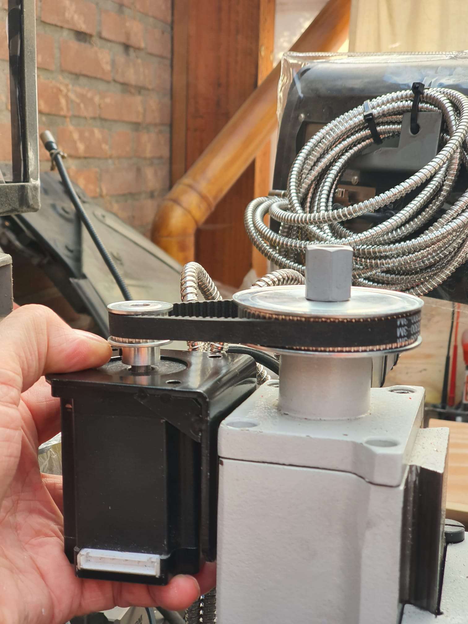
So, also the external add-on drivers that do closed loop control can be used. < I was thinking to make this my additional project: Try to do sensorless homing on the Y axes with this, use very low power and switch off the Closed loop during homing.. If I can get this to work, you will read all about it!>
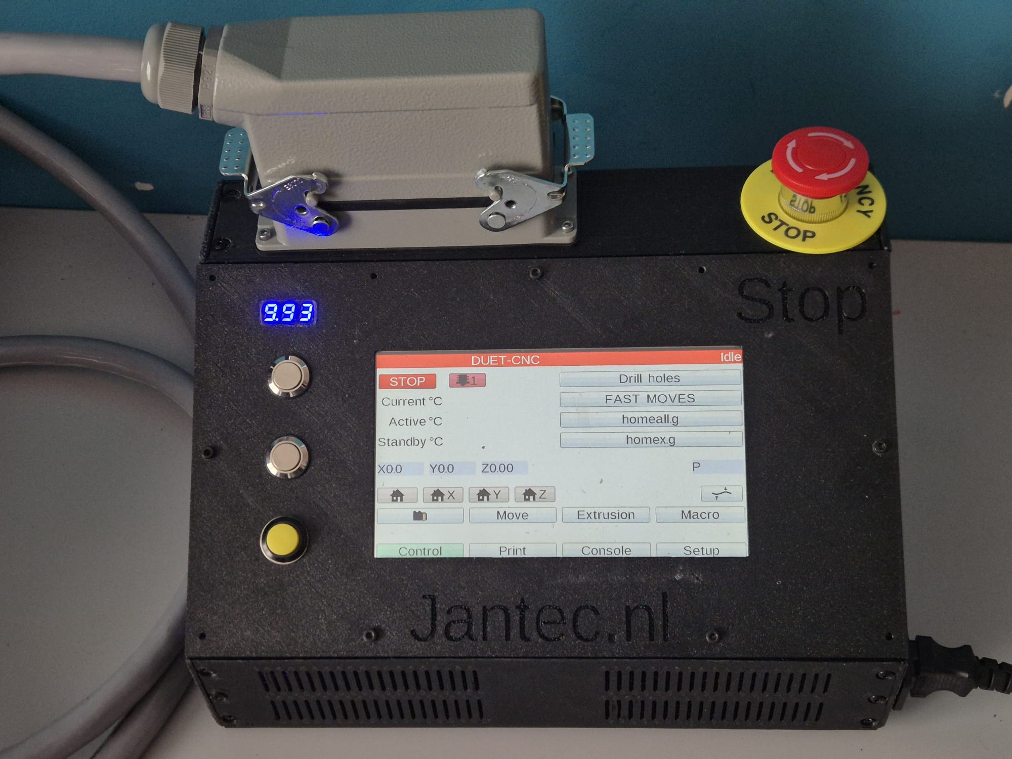
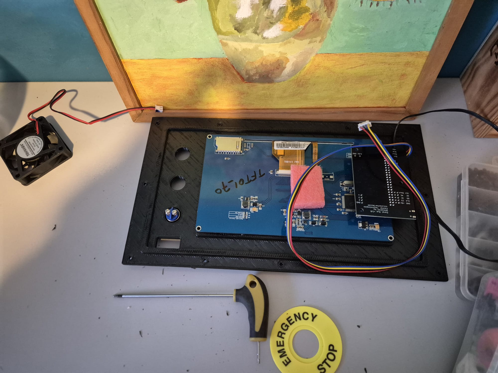
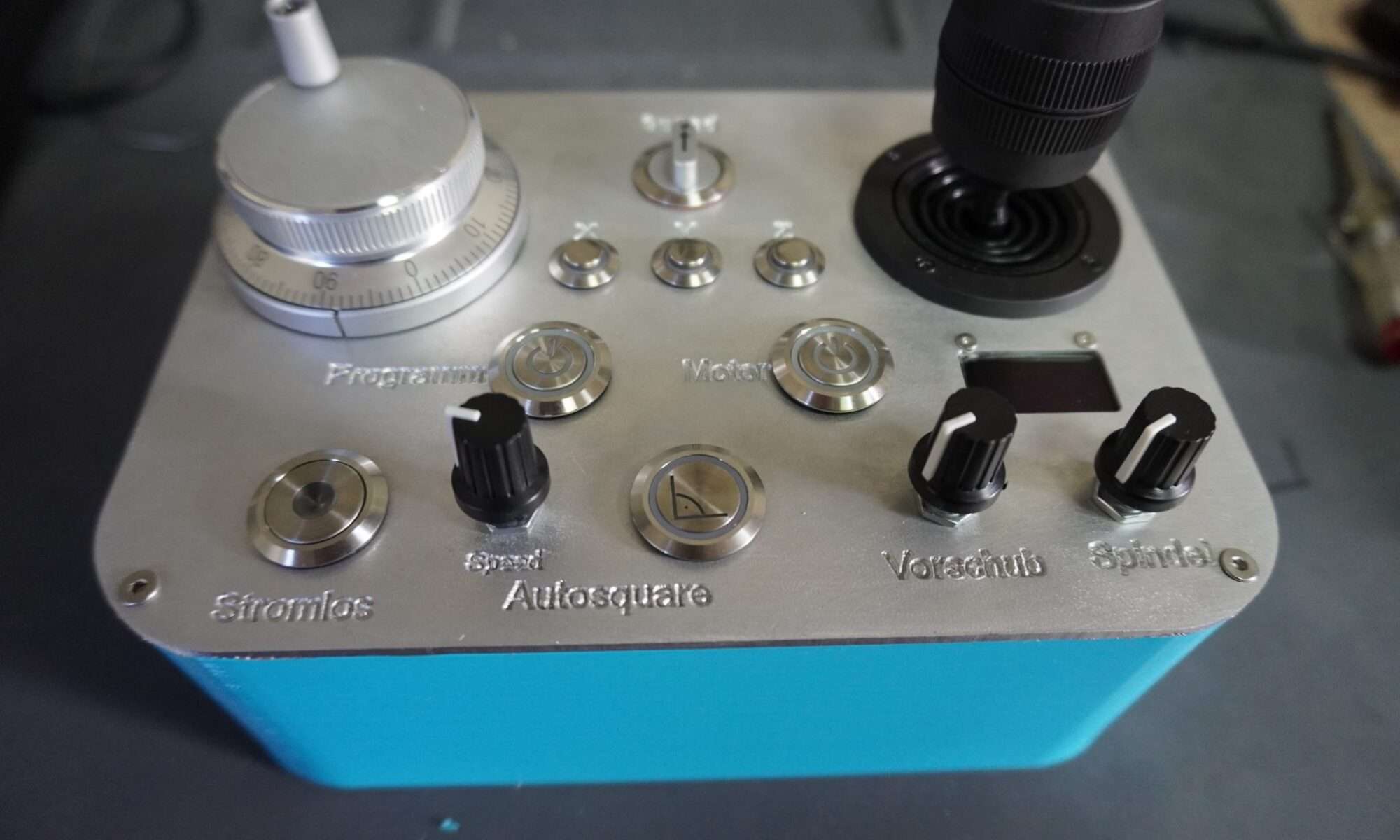
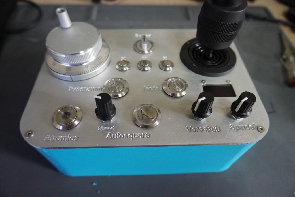
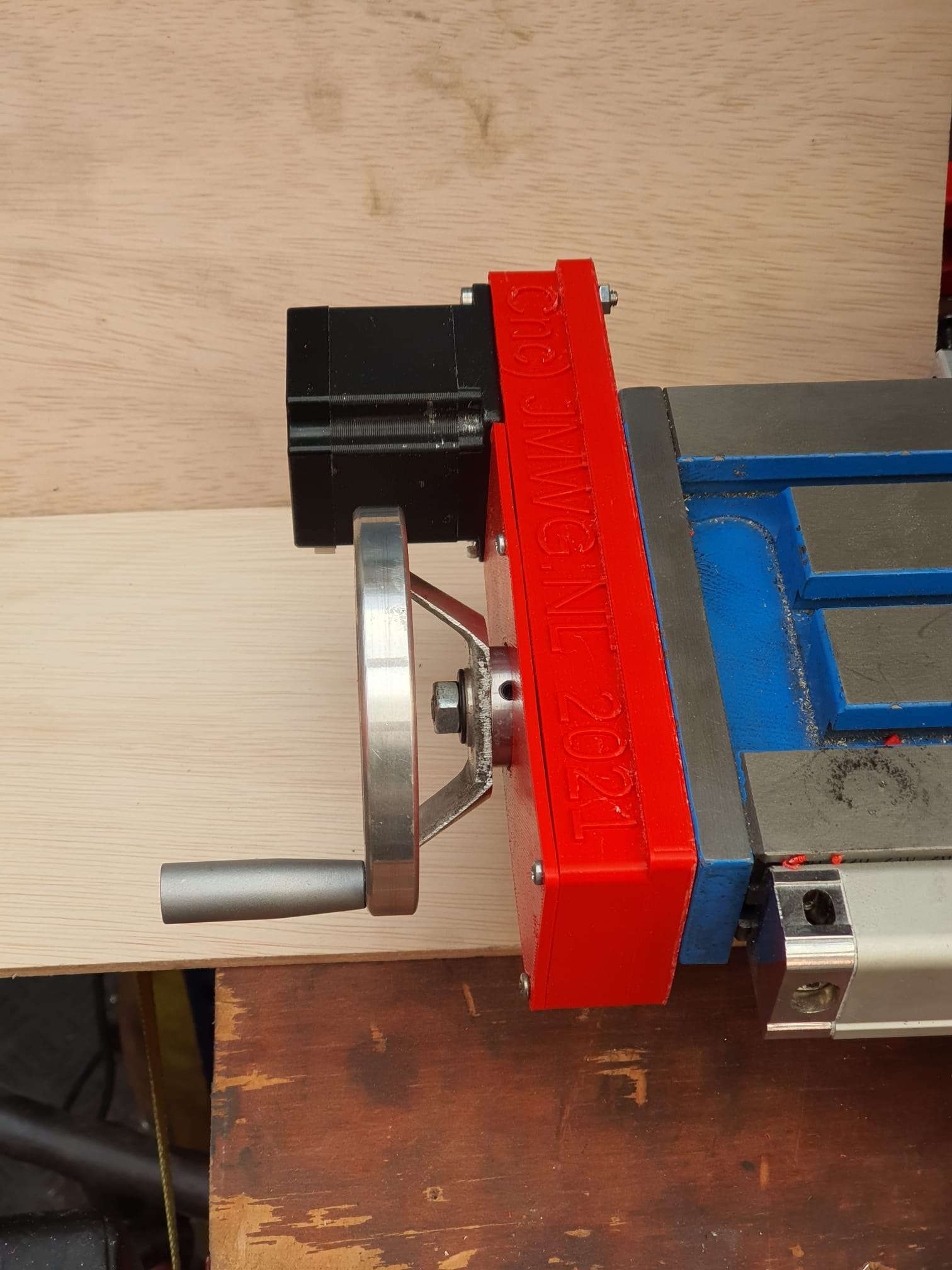
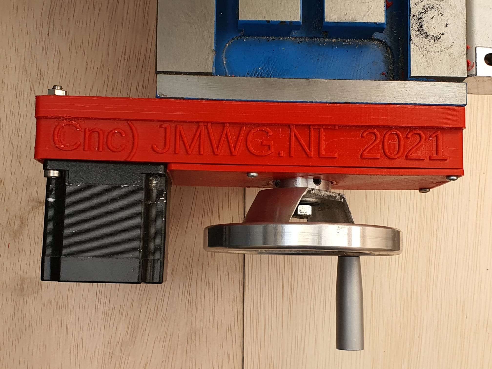
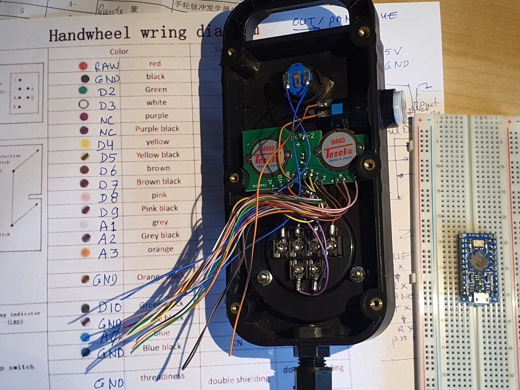
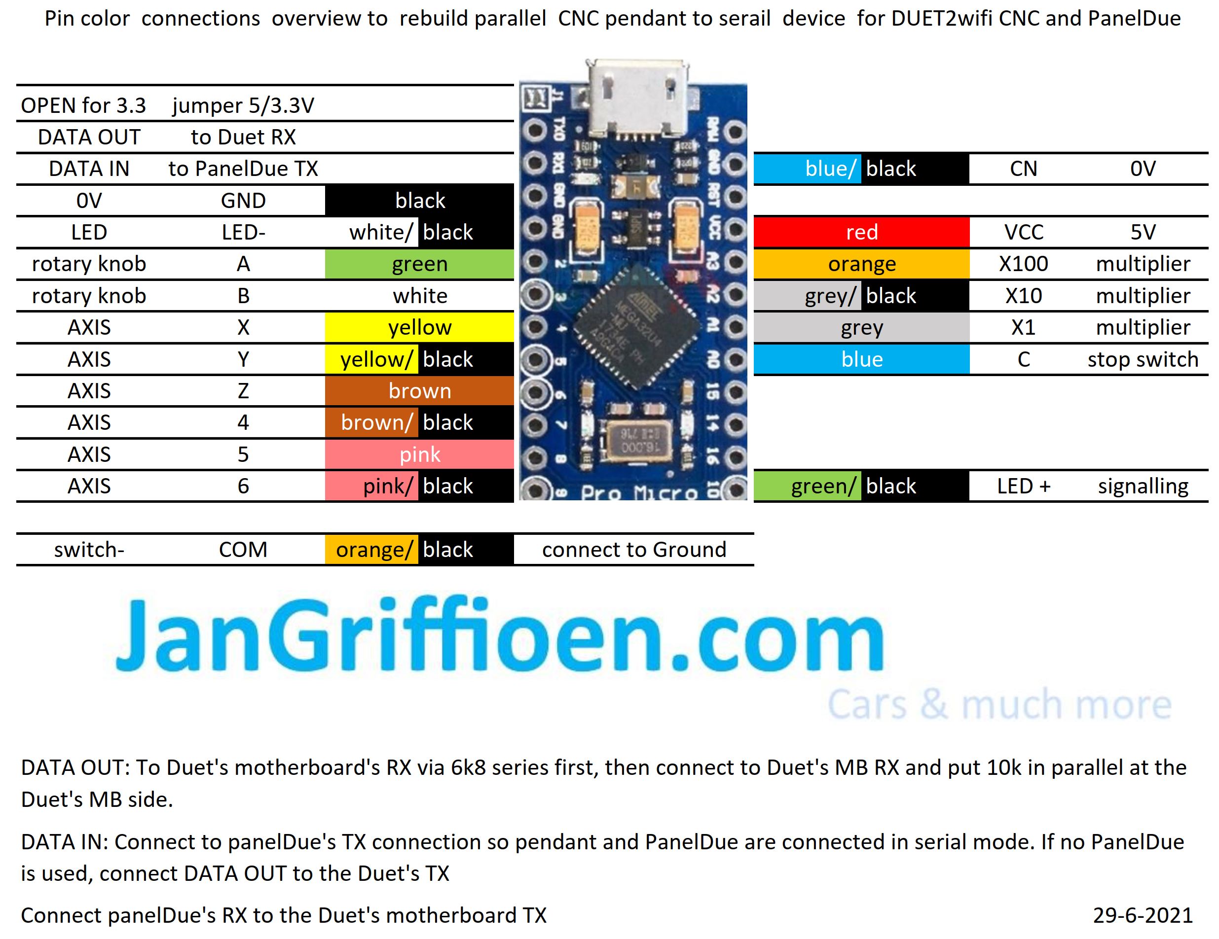
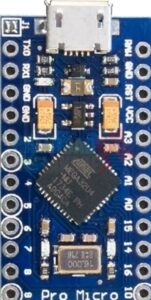
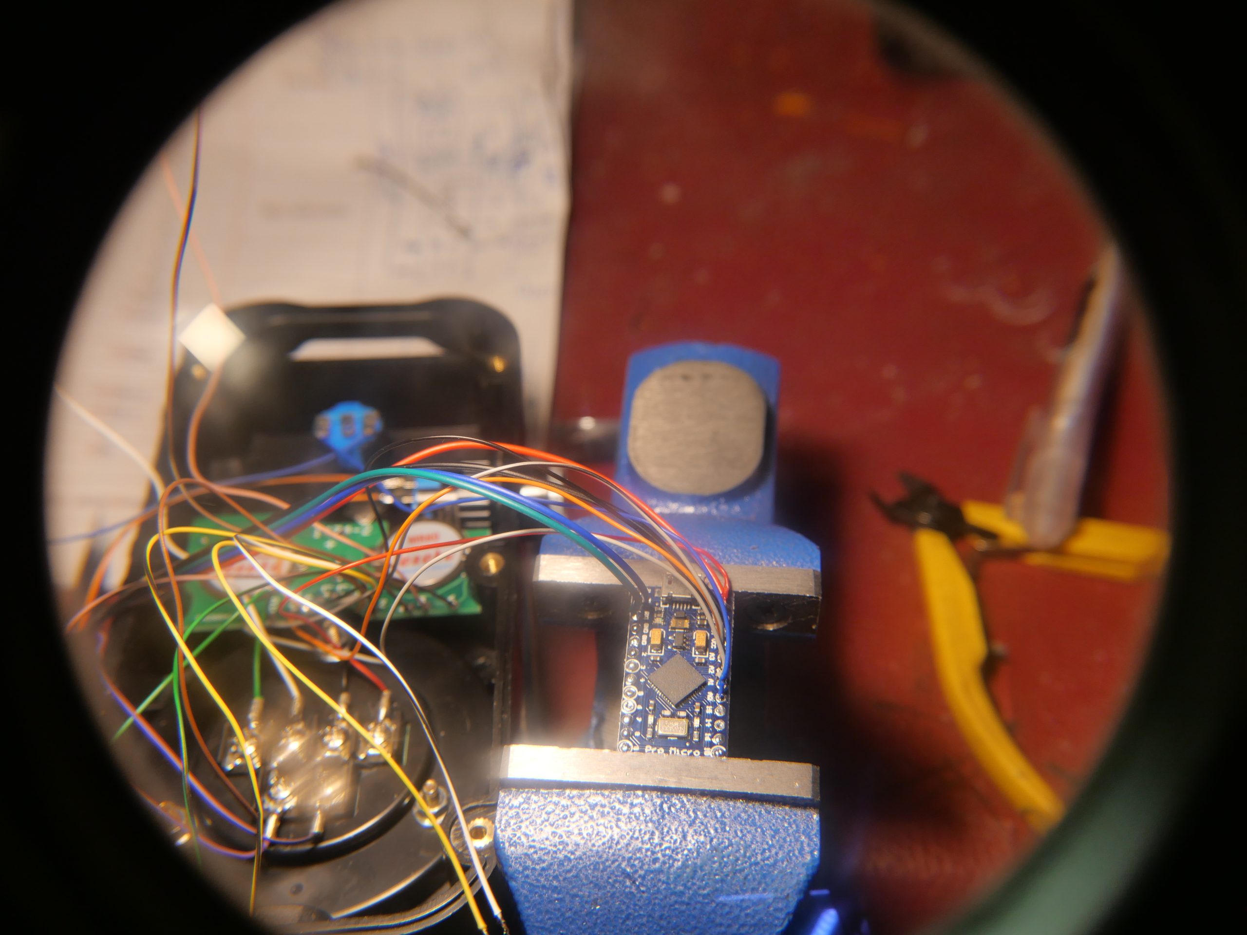
For the Duet, a setup is available on the Duet website to use an original pendant handwheel unit and add an arduino Pro micro to make a serial interface for connecting to the Duet! That is a very welcome addition. See this post!
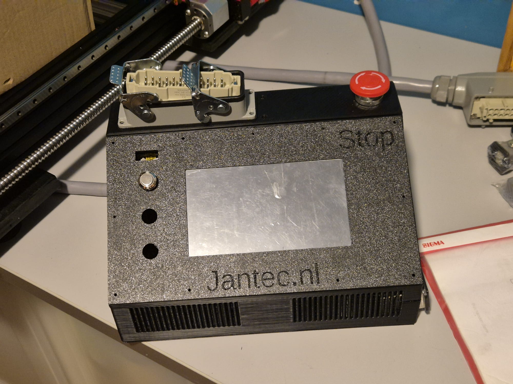
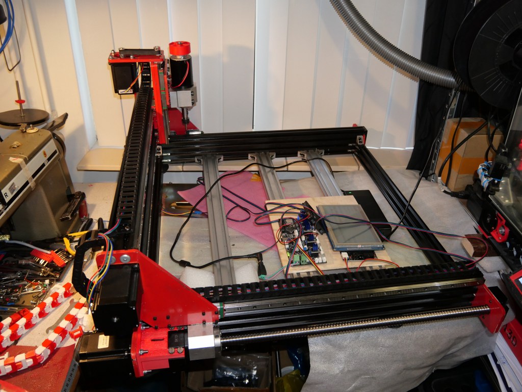
In the next part of this post my current config file with endstops for Duet/reprap/FLY is shown, as this is operaional for the Indymill.
BE AWARE to use the most current DEVELOPMENT firmware versions for a) the board’s initial firmware, b) the DWC firmware and c) the wifi esp program!
; Configuration file for Board: fly_cdyv2 (STMWiFi)
; Firmware: RepRapFirmware for STM32F4 based Boards 3.3beta1_3 (2021-03-08)
; Duet WiFi Server Version: 1.25-01S-D
; DWC from Sidarius, specificlly redesigned for use with CNC 3-axis
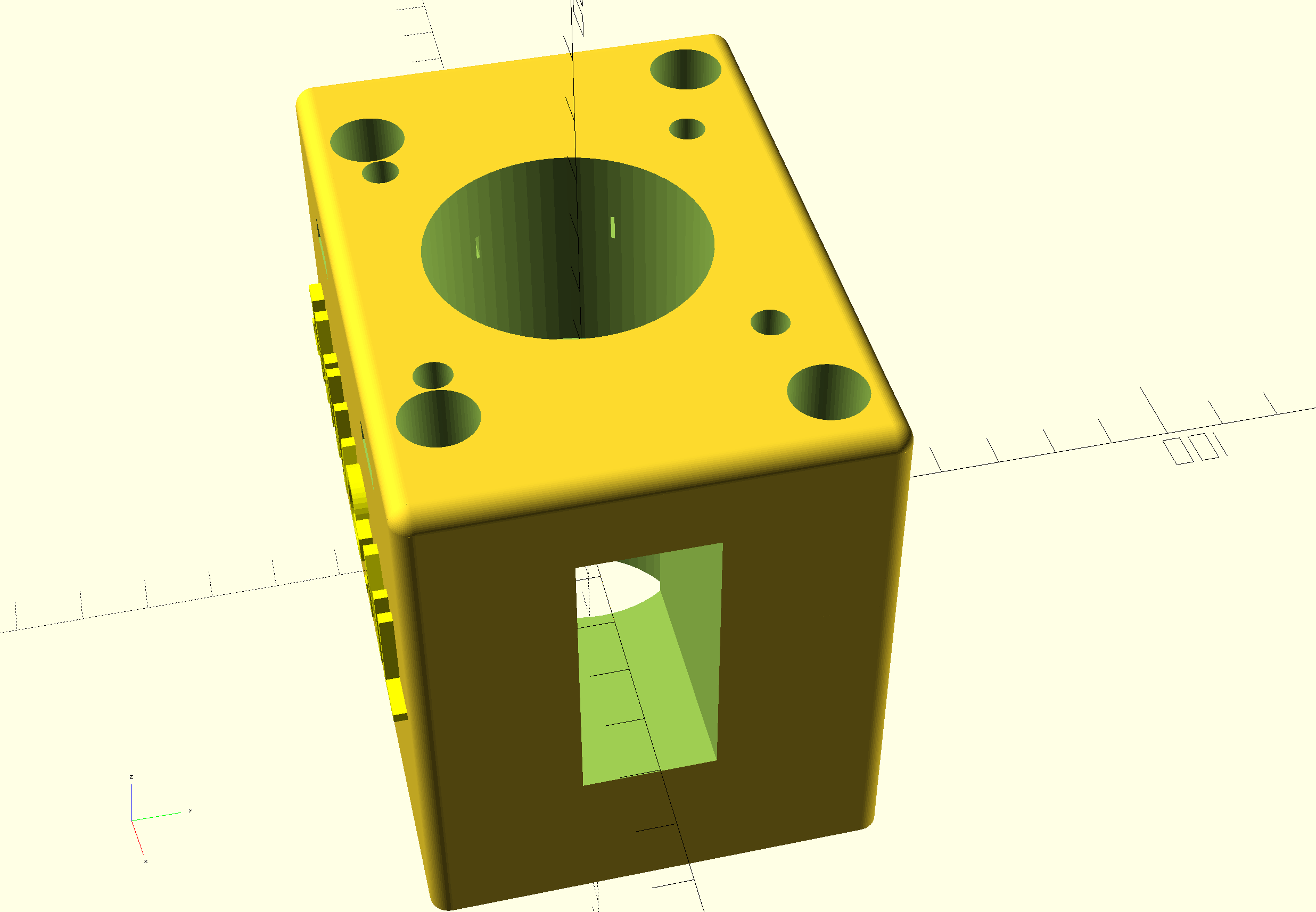
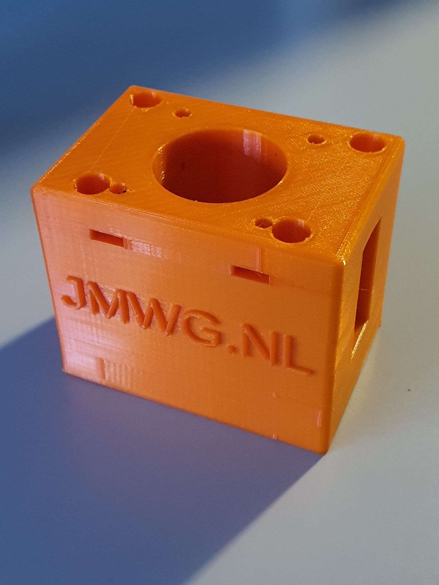
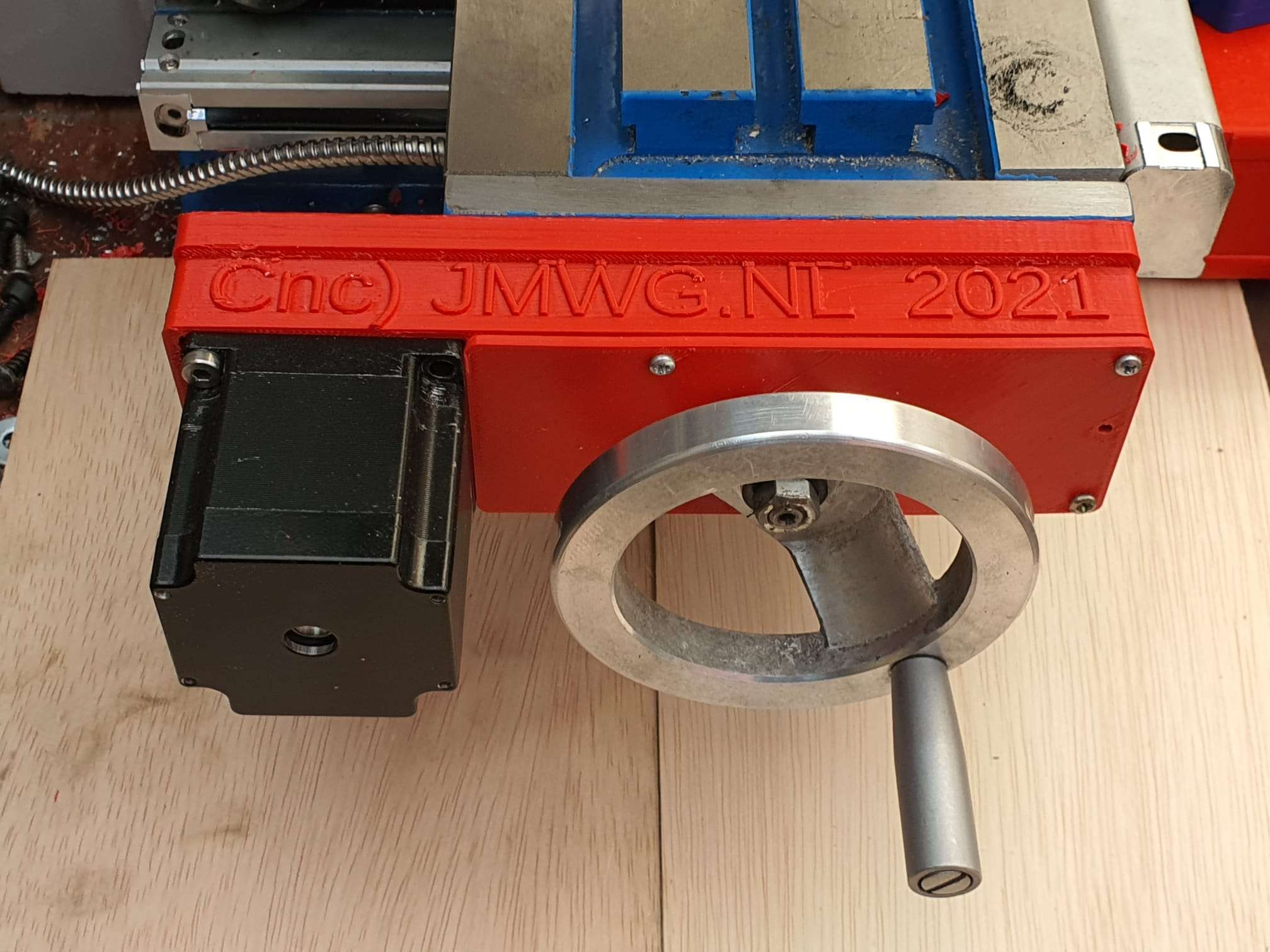
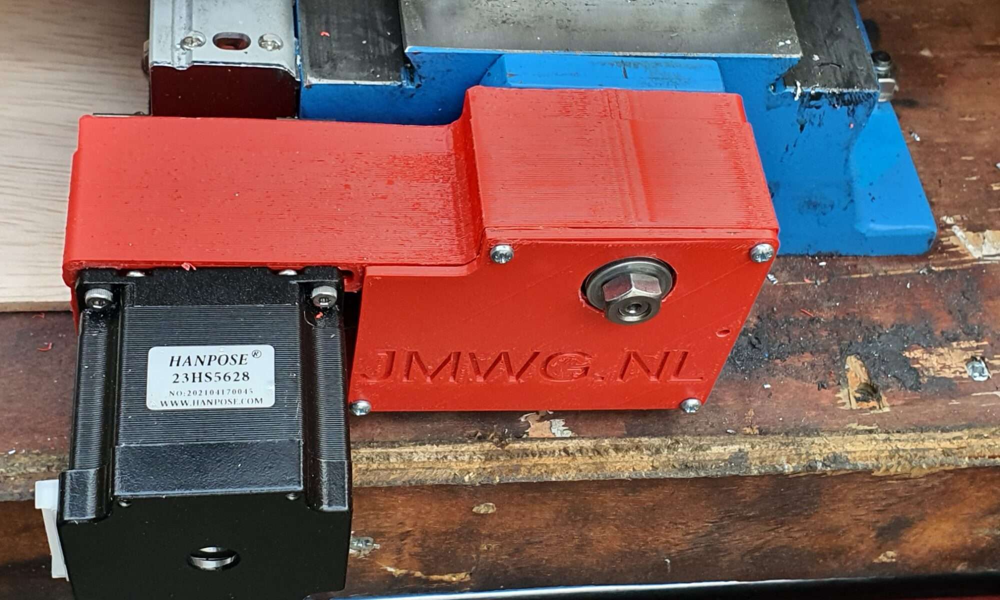
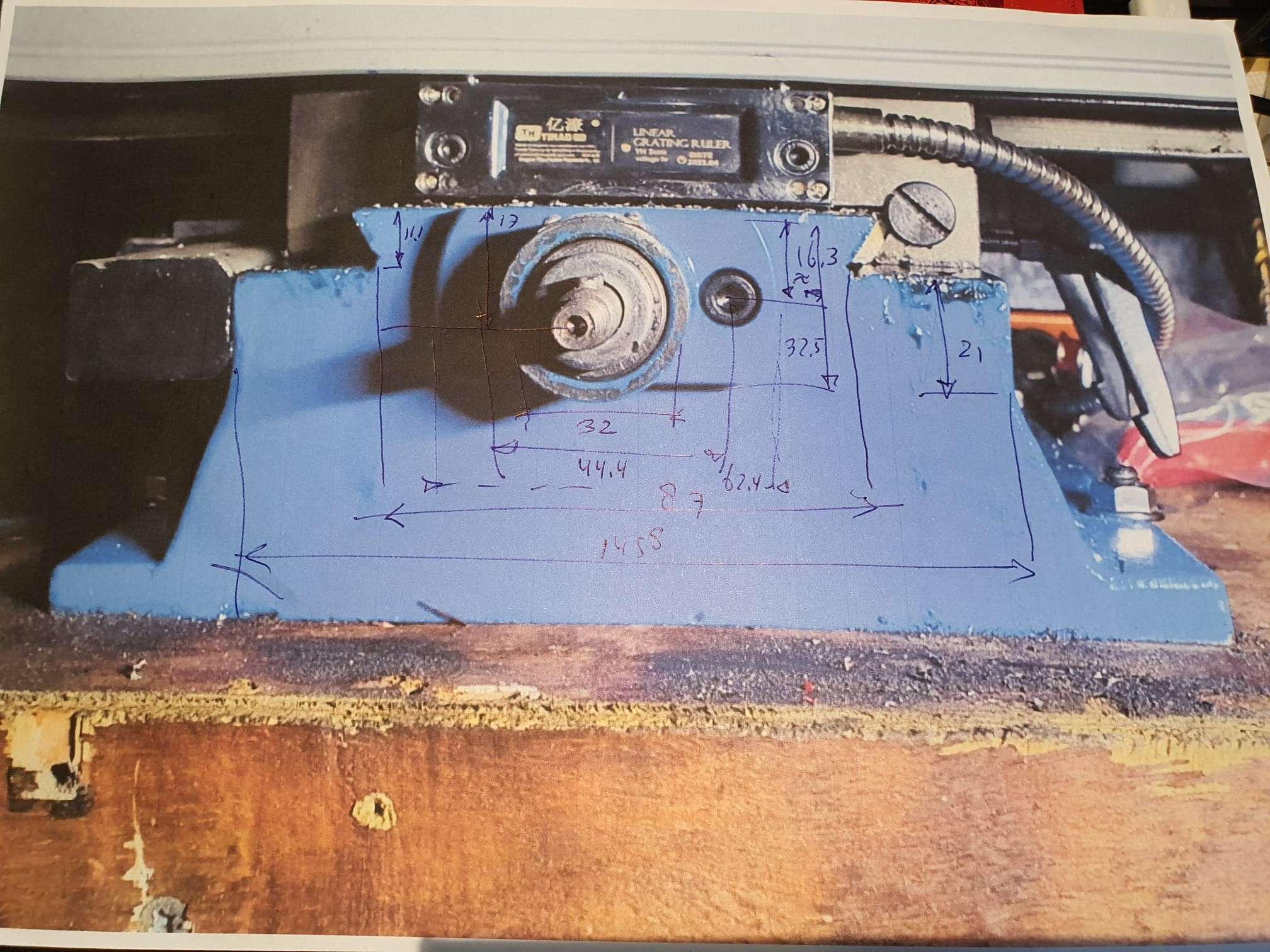
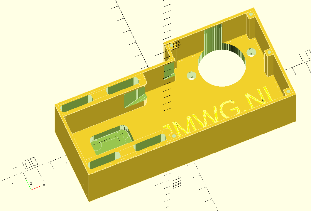
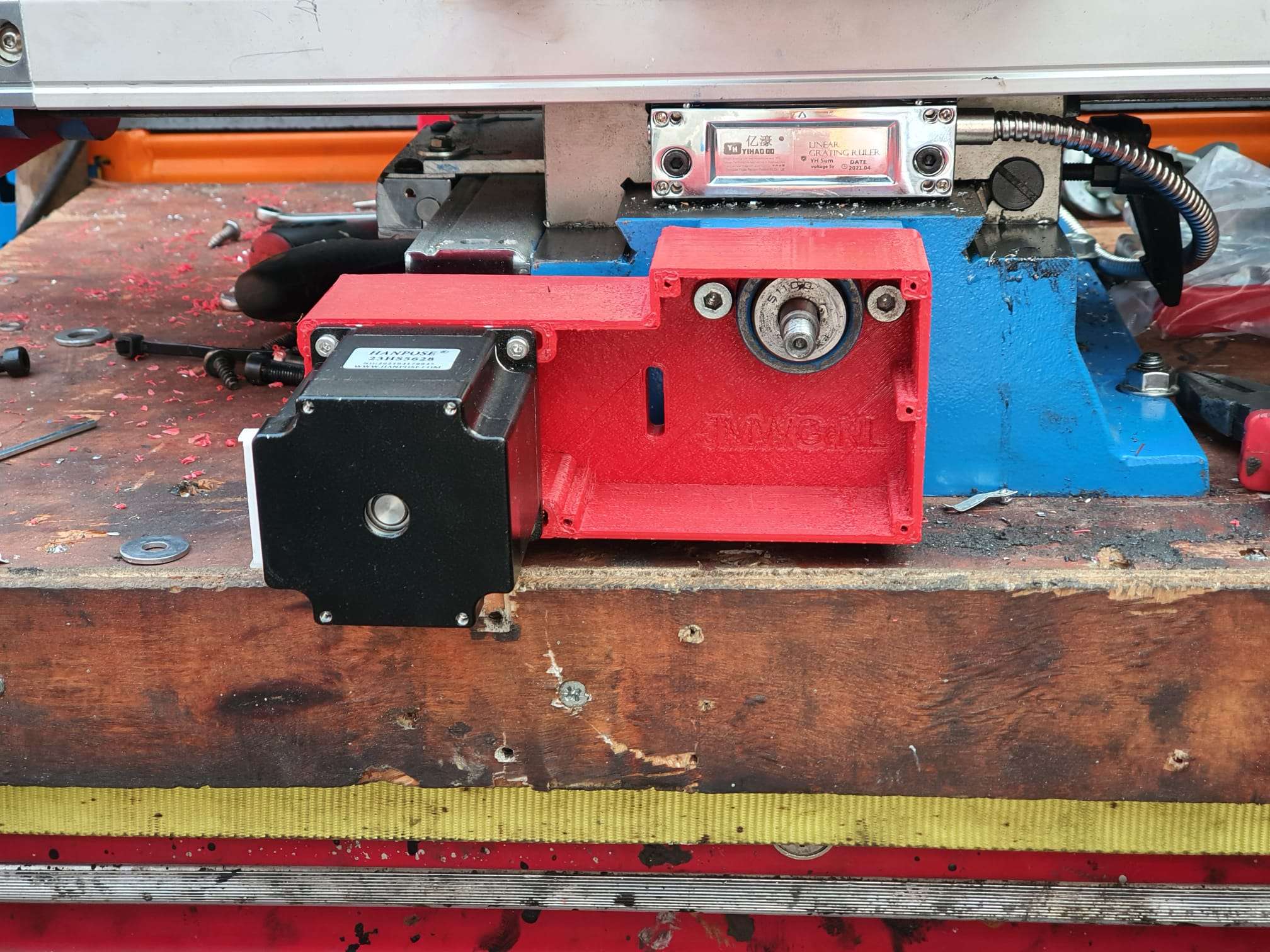
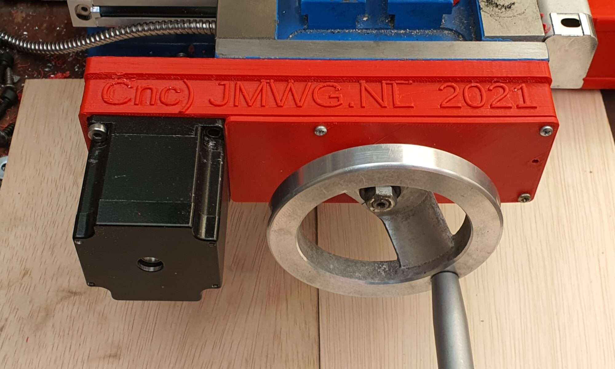
; customized by Jan Griffioen sales@jmwg.nl 2021 04 08
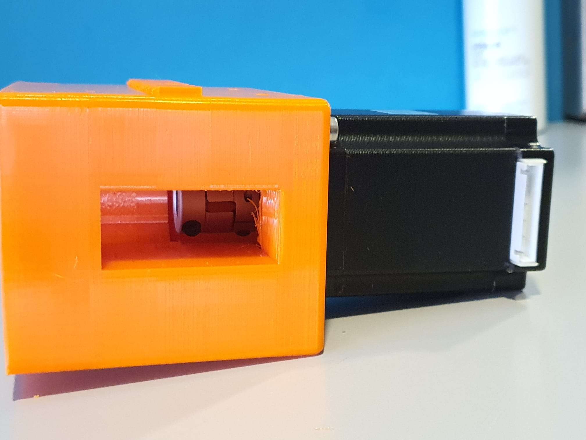
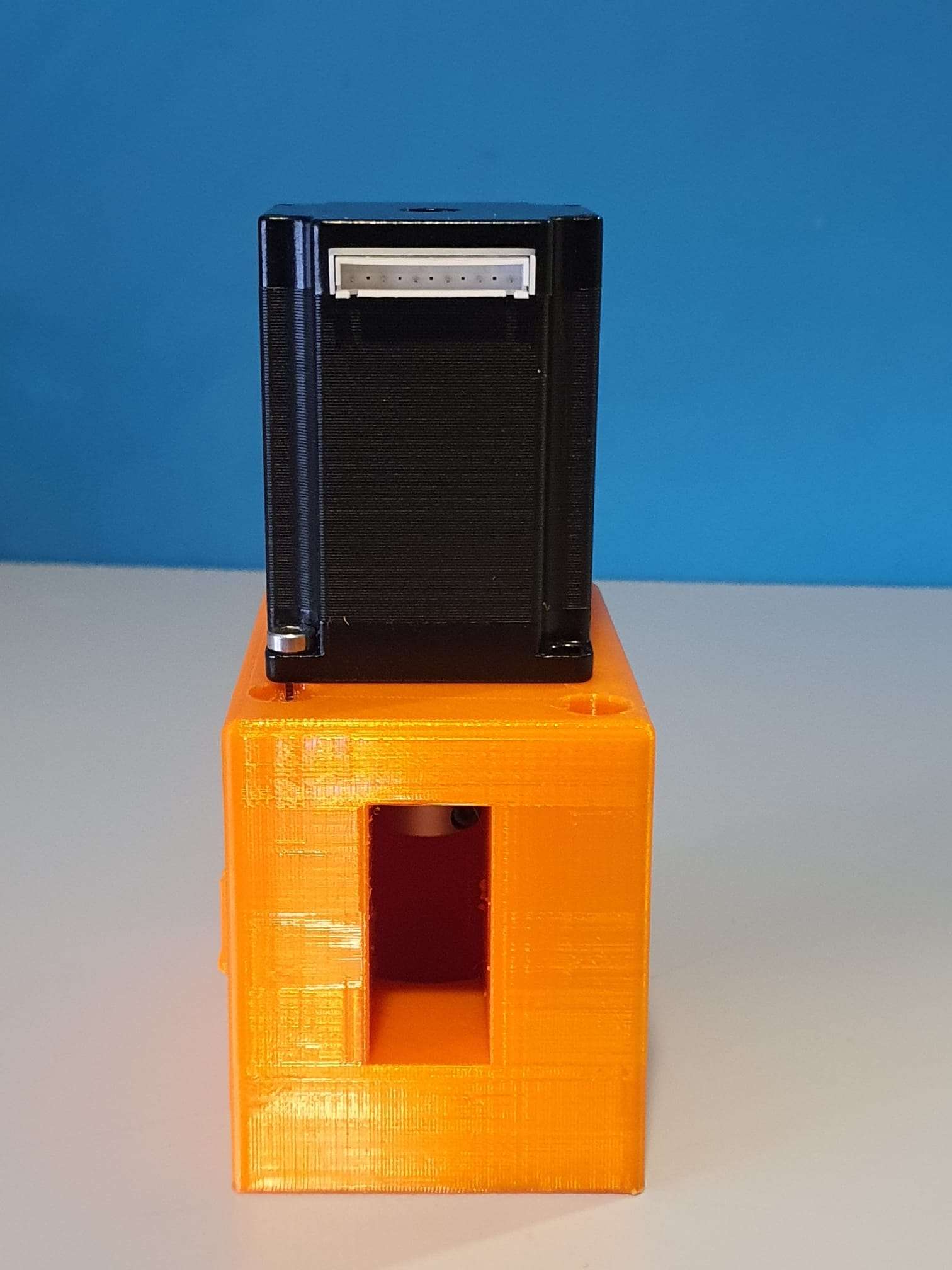
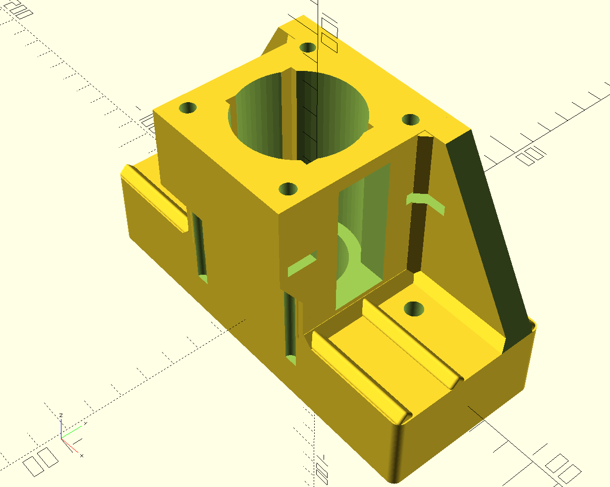
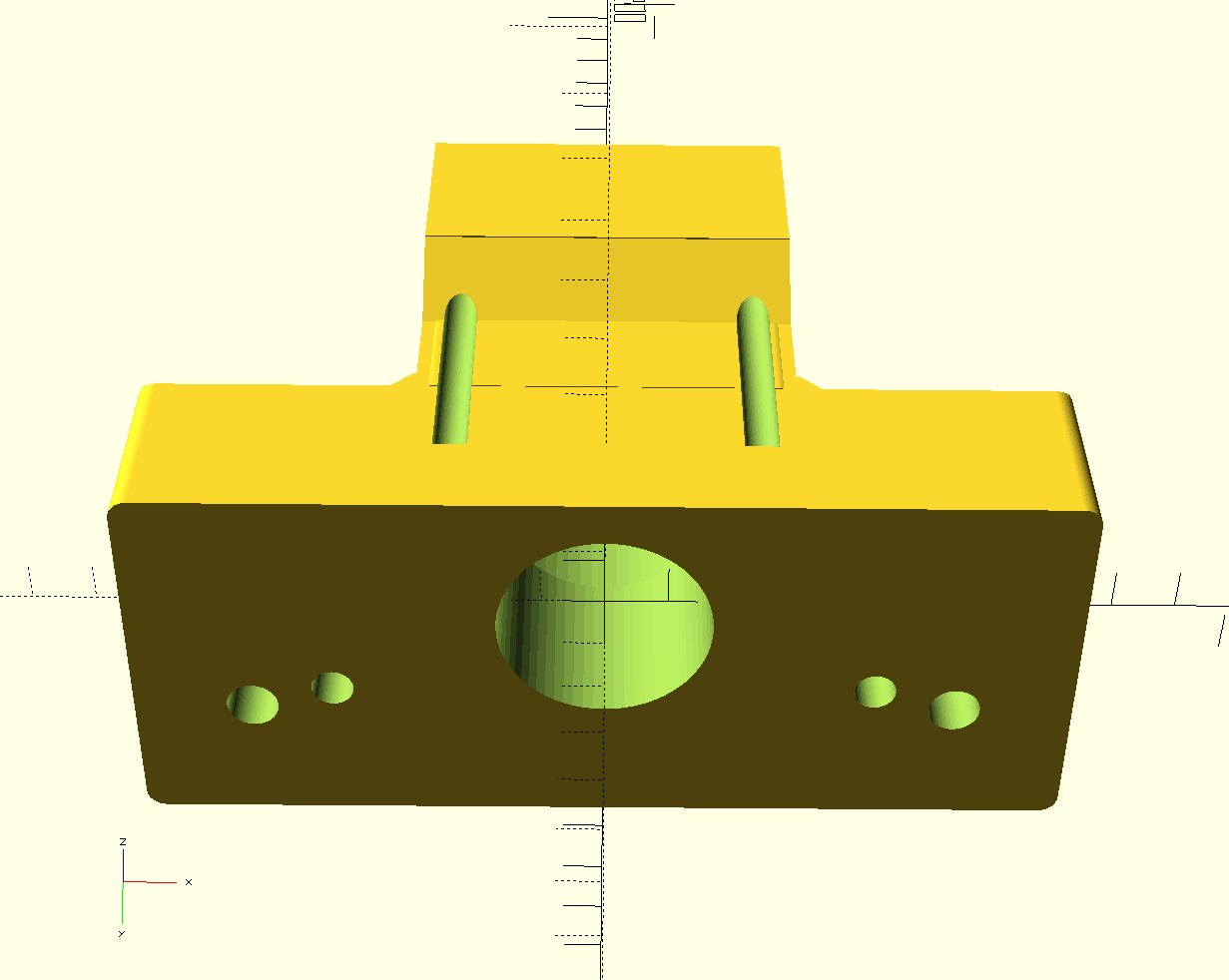
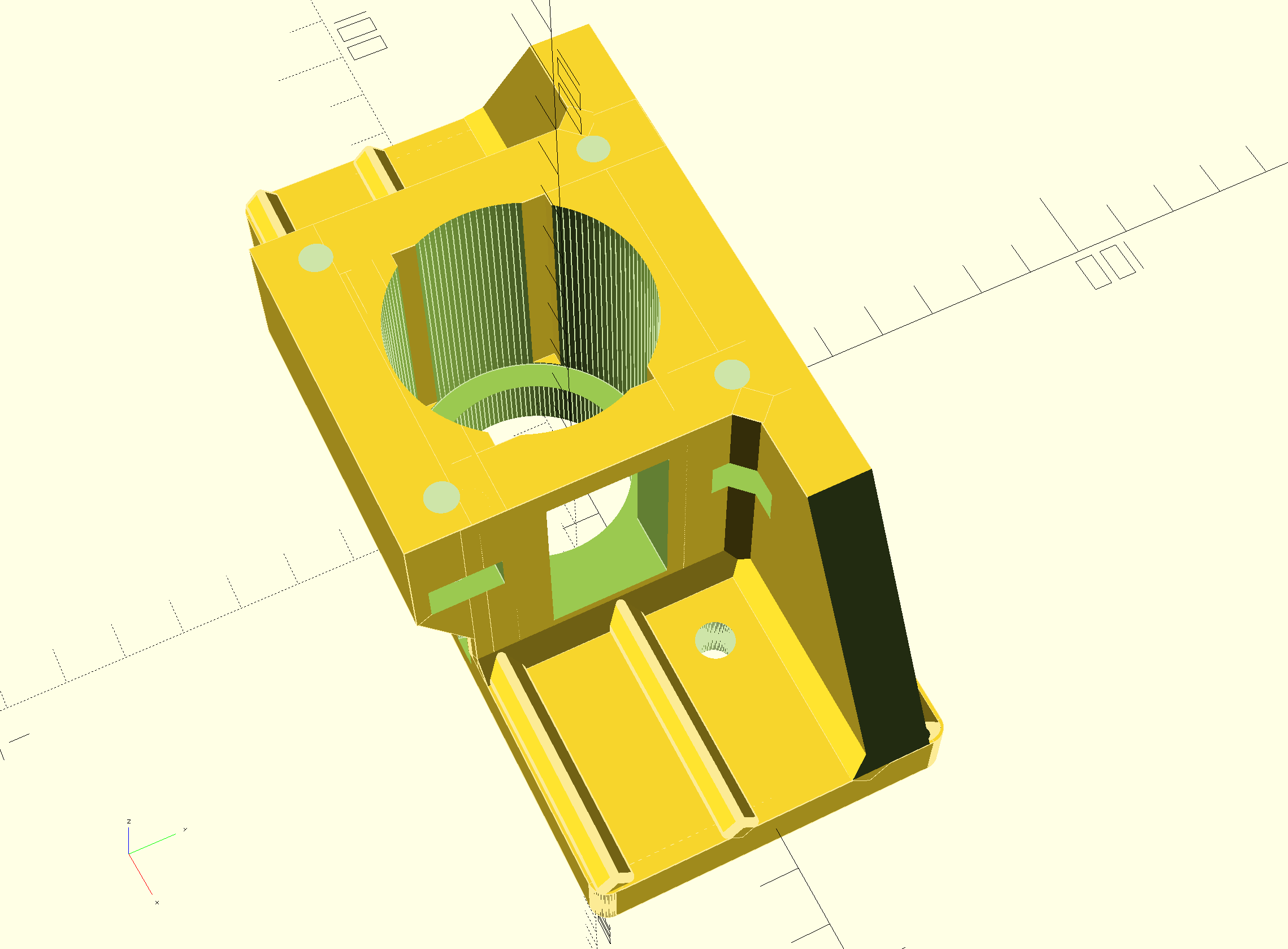
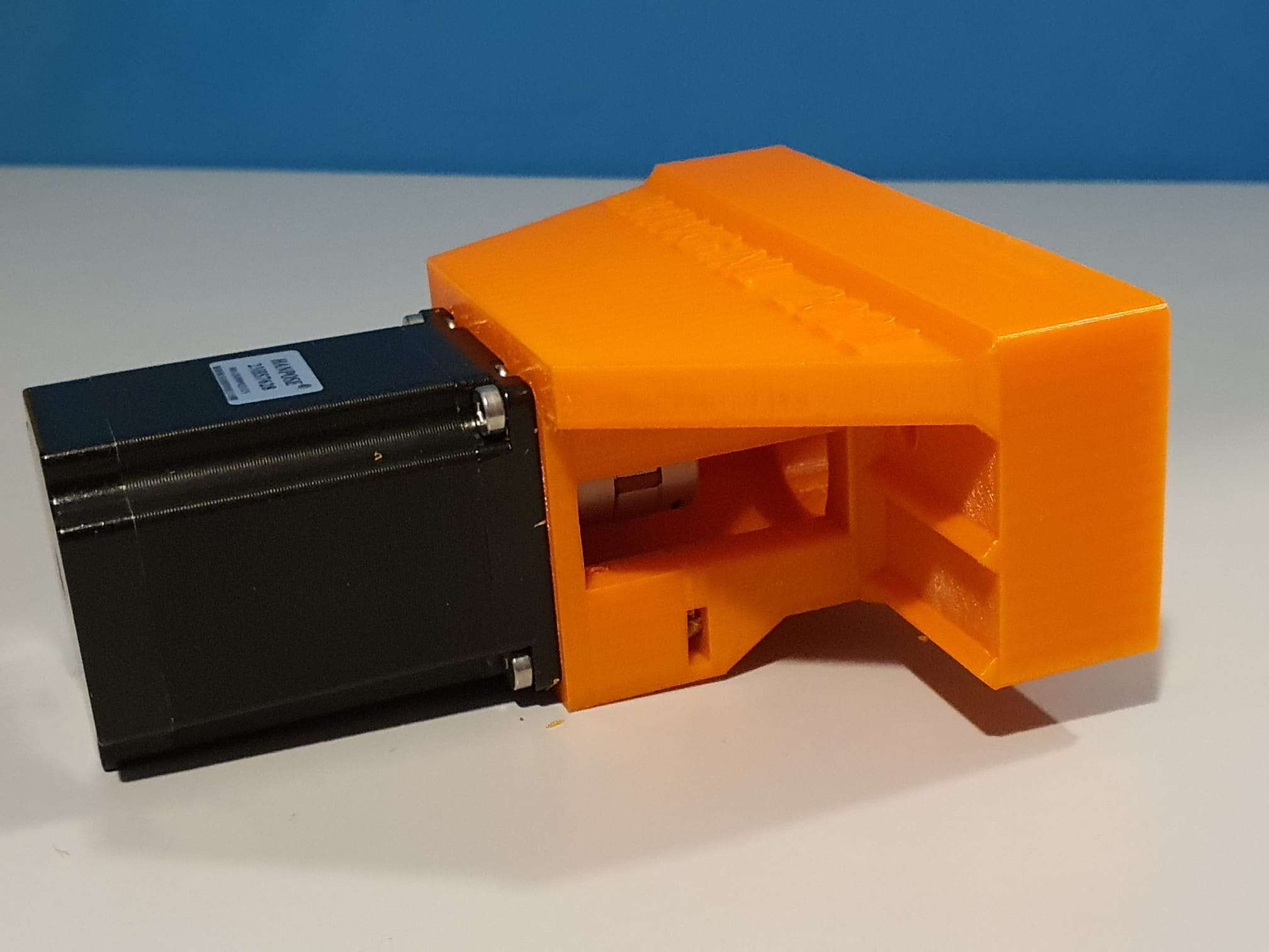
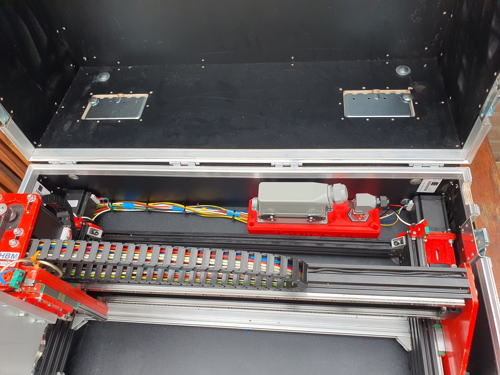
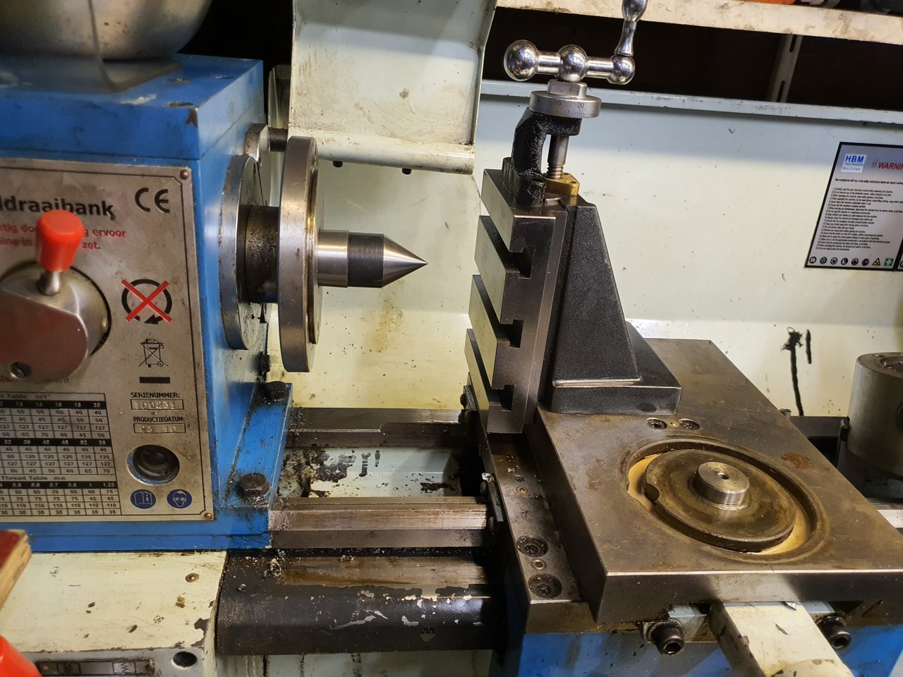
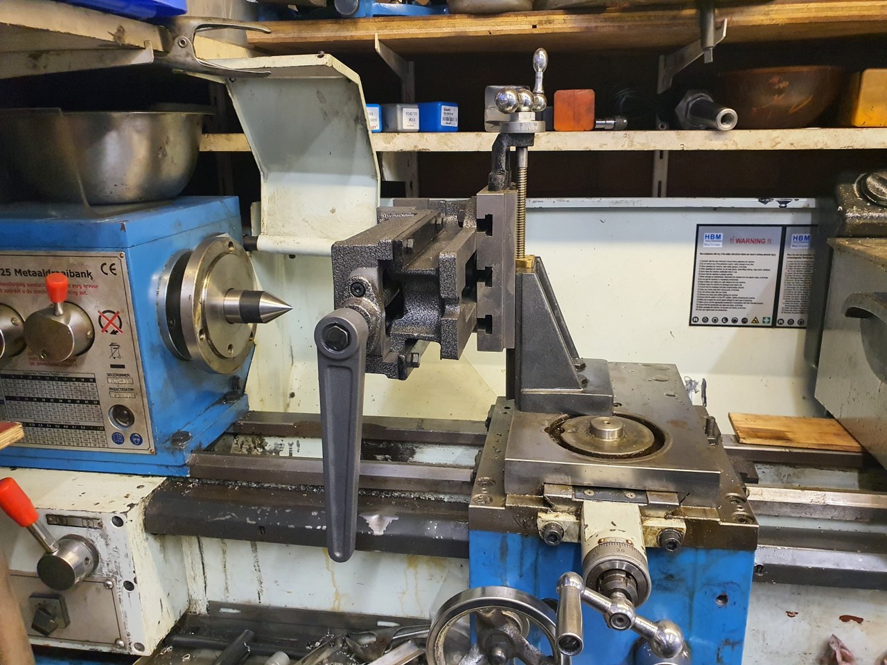
; Made for a CNC Cartesian printer with single X,double Y and single Z steppers and a single spindle with external driver.
; General preferences —————————————————————————————————————-
M453 ; CNC Mode
G90 ; send absolute coordinates
M83 ; and relative extruder moves
M550 PDUET_CNC ; set printer name
M551 Preprap ; Machine password
M552 S1 ; WIFI ON
; Network —————————————————————————————————————————-
M586 P0 S1 ; enable HTTP
M586 P1 S0 ; disable FTP
M586 P2 S0 ; disable Telnet
M552 P0.0.0.0 ; IP address (0.0.0.0 = use DHCP)
M554 P192.168.178.1 ; Gateway
M553 P255.255.255.0 ; Netmask
M555 P2 ; Set output to look like Marlin
M575 P1 S1 B57600 ; comms settings S1 for Original PanelDue and Fysetc 7 inch TFT =OK
; Drives —————————————————————————————————————————-
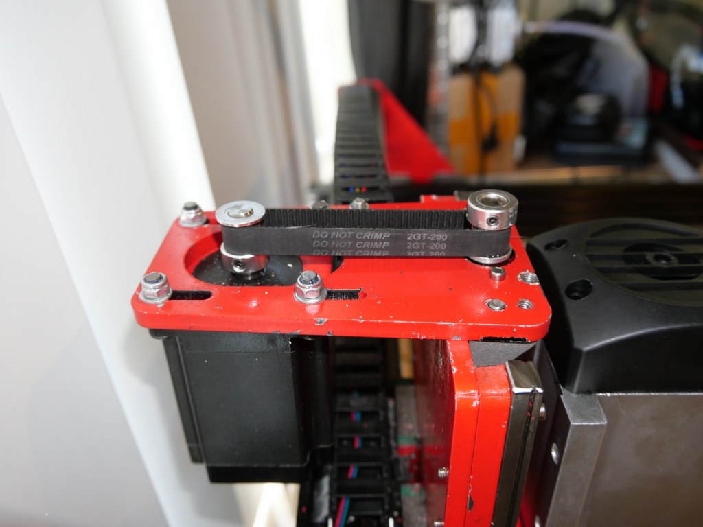
M569 P0 S1 D2 ; physical drive 0 goes forwards using default driver timings
M569 P1 S1 D2 ; physical drive 1 goes forwards using default driver timings
M569 P2 S1 D2 ; physical drive 2 goes forwards using default driver timings
M569 P3 S1 D2 ; physical drive 3 goes forwards using default driver timings
M584 X0 Y1:2 Z3 ; set drive mapping
M350 X16 Y16:16 Z16 I1 ; configure microstepping with interpolation
M92 X640 Y640:640 Z1600 ; set steps per mm
M566 X500 Y500 Z300 ; Set maximum instantaneous speed changes (mm/min)
M203 X2700 Y1400 Z1000 ; Set maximum speeds (mm/min)
M201 X300 Y300 Z150 ; Set accelerations (mm/s^2)
M906 X1800 Y1800 Z1800 I30 ; set motor currents (mA) and motor idle factor in per cent
M84 S100 ; Set idle timeout
; Axis Limits ————————————————————————————————————————-
M208 X0 Y0 Z0 S1 ; set axis minima
M208 X500 Y480 Z100 S0 ; set axis maxima
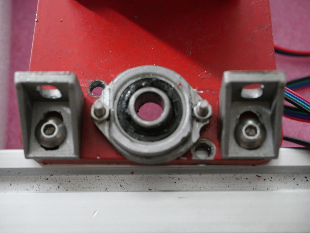
; Endstops —————————————————————————————————————————-
M574 X1 S1 P”^xmin” ; configure active-high endstop for low end = LEFT on X via pin xmin
M574 Y1 S1 P”^ymin+^ymax” ; configure active-high endstop for low end = REAR on Y1 and Y2 via pin ymin and ymax
M574 Z2 S1 P”^zmax” ; configure active-high endstop for high end = TOP on Z via pin zmax
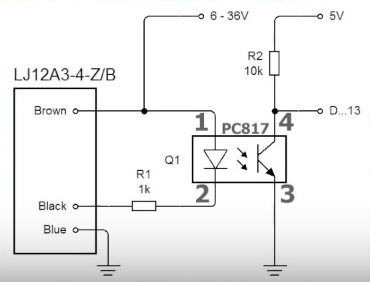
; Z-Probe ——————————————————————————————————————————
; a probe must be defined here to have a Z=0 DATUM, including the offset (when there is any, If you use the tip of the tool no offset is required. OR, use manual Z-datum setting via a dedicated macro!
; Mesh G29 —————————————————————————————————————-
;M557 X15:215 Y15:195 S20 ; define mesh grid to be called upon by G29 for an authentic Mesh bed levelling IF this is required and possible
; Fans ———————————————————————————————————————————–
M950 F0 C”fan0″ Q500 ; create fan 0 on pin fan0 and set its frequency
M106 P0 S0.5 H-1 ; set fan 0 value. Thermostatic control is turned off
; Tool definition section; —————————————————————————————————————-
M950 R0 C”!e2heat” L25000 ; Create spindle index 0, with PWM pin on heater 2 output and 25000 RPM achieved at full PWM. At this port, add a PWM-> Voltage 1-10V converter!
M563 P1 S”Spindle 1″ R0 ; Create tool 1 with spindle 0 and call it “Spindle 1”
; Miscellaneous —————————————————————————————————————————-
M140 H-1 ; Disable heated bed
M564 S1 H1 ; Disable jog commands when not homed
M98 P”customconfig.g” ; Execute custom config settings
; Epilogue ———————————————————————————————————————————
;M556 S78 X0 Y0 Z0 ; Axis compensation here if needed
;m98 P/sys/leds_show.g ; Neopixels show (max number is 60)
;m98 P/sys/leds_off.g ; Neopixels OFF (max number is 60)
T0 : select first Tool
M501 ; execute config_override.g


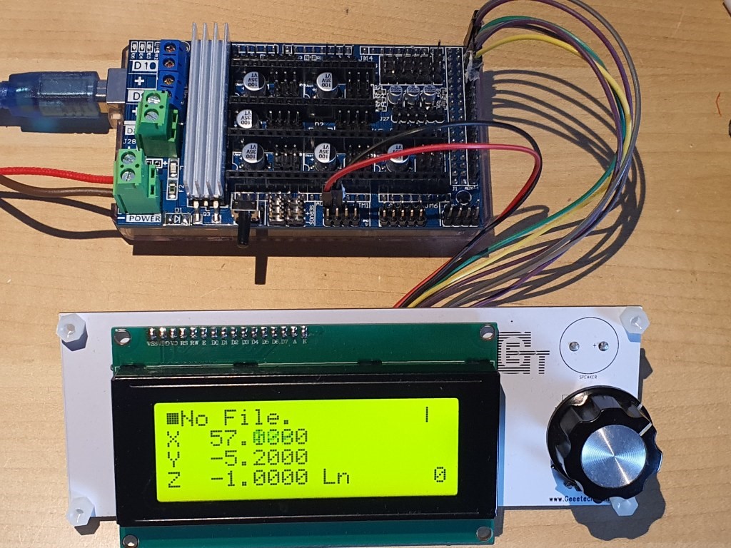
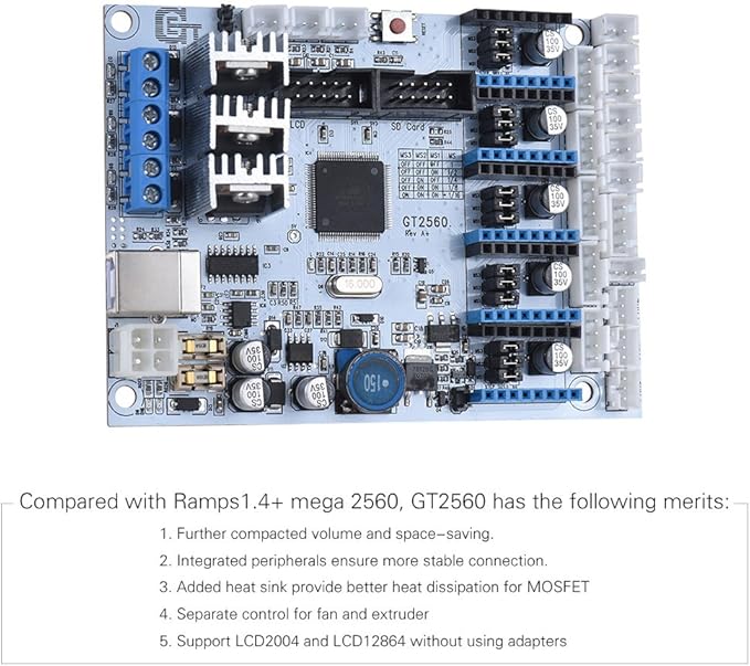
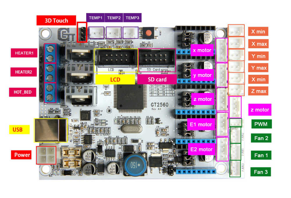 The main reason to NOT use this is the fact that the GT2560 board just has not got enough pins available onboard for things like a handwheel and other outputs for accessories. The second thing that prevents me from going this way is the fact that it proved impossible to have a functional LCD attached that shows things like position, speed, status et cetera.
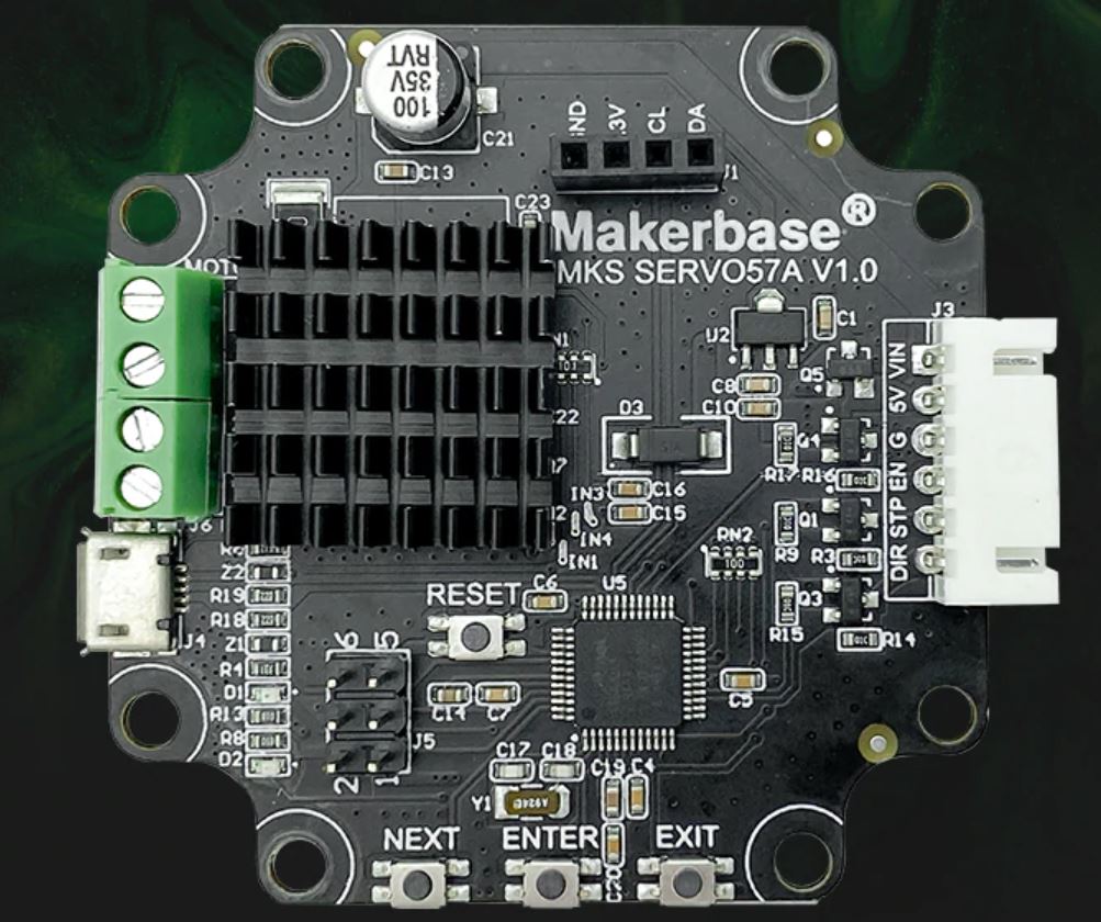
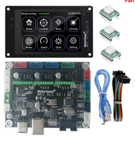 Also for this setup: No option for squaring the dual Y axis setup. But- this is a very neat solution for smaller machines. or larger, if you use external drivers. The nice option of this setup is the 3.5 inch LCD that also comes preconfigured for CNC. I use this for my small 3018 CNC.
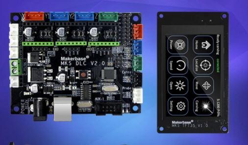


 :
:

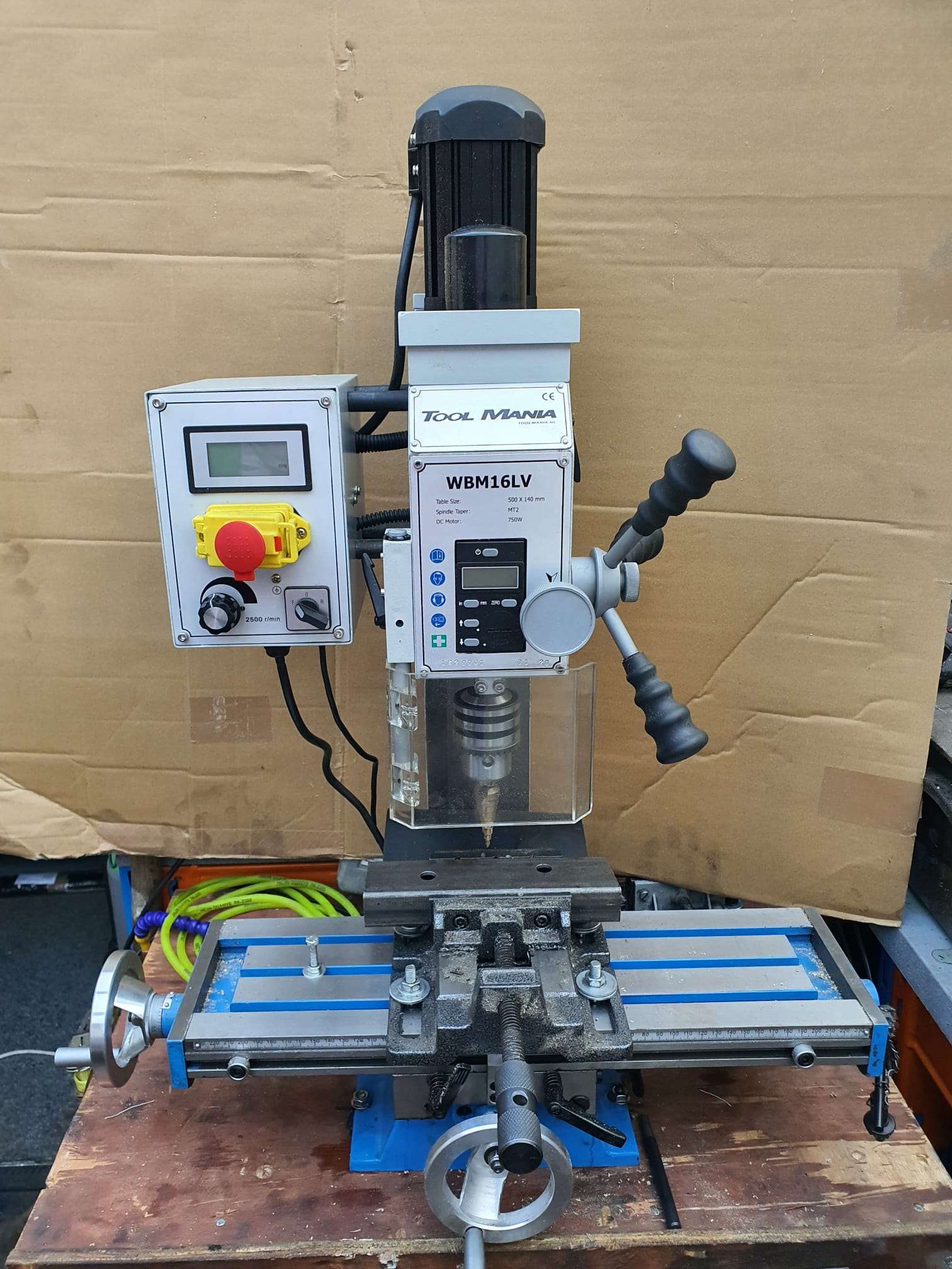

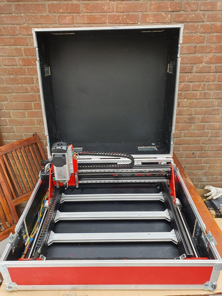

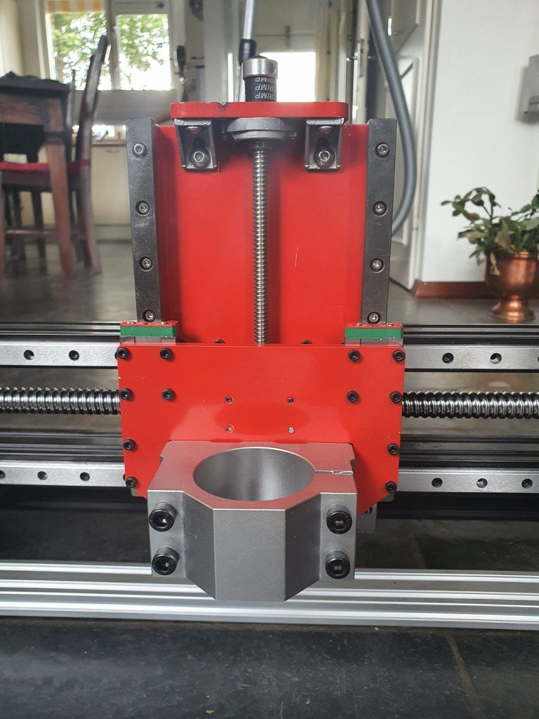
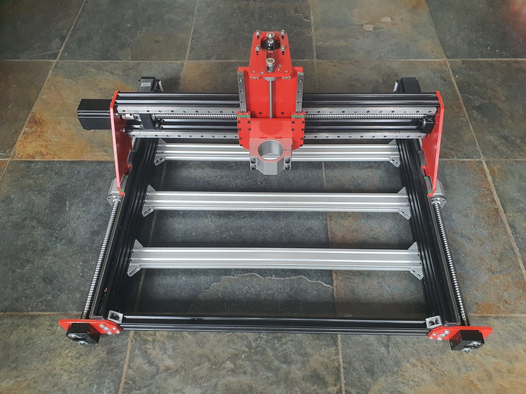
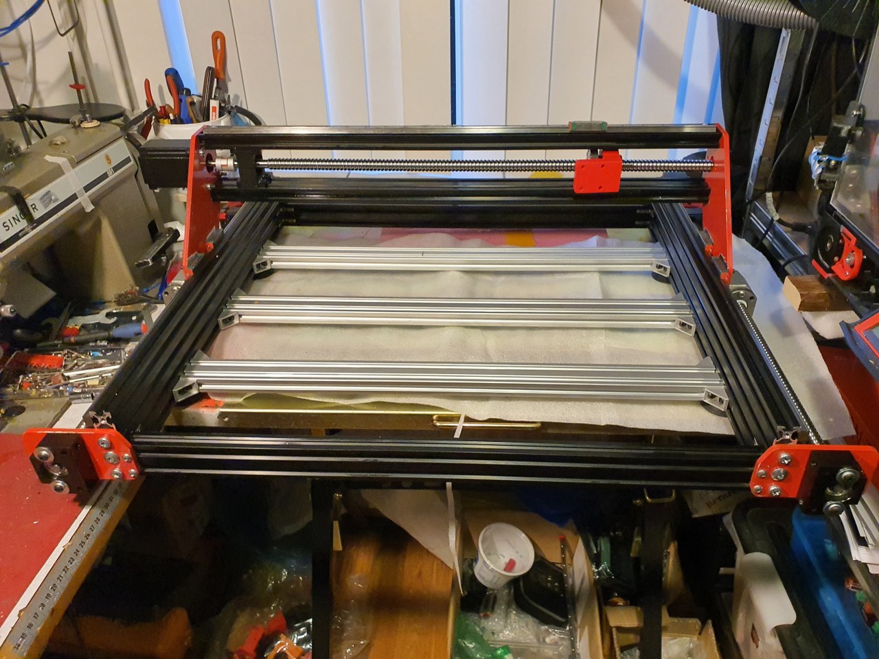
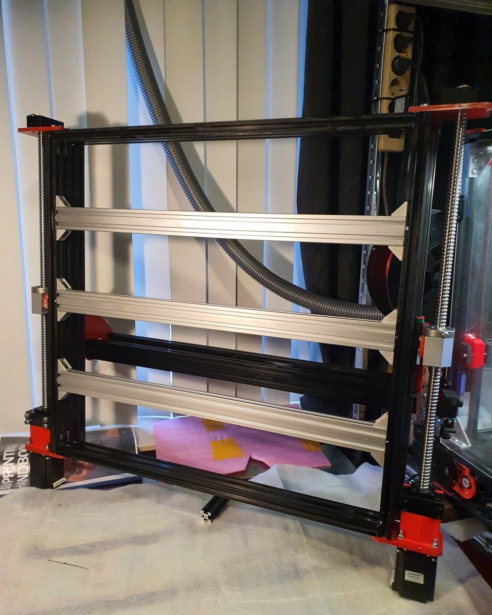
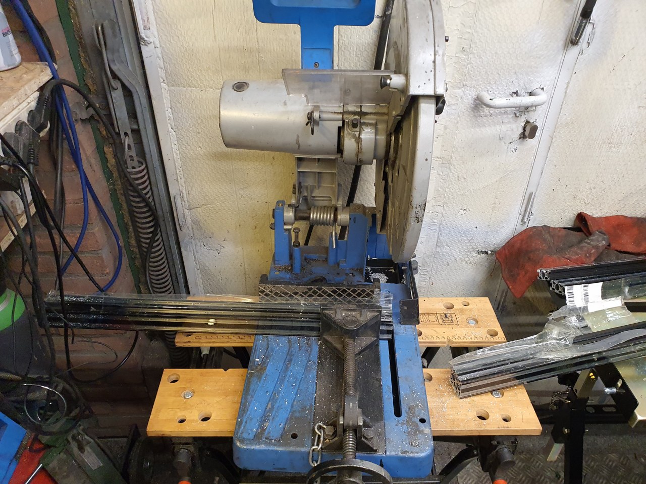
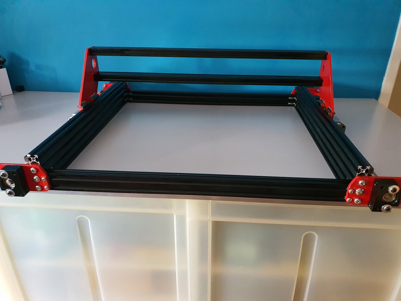
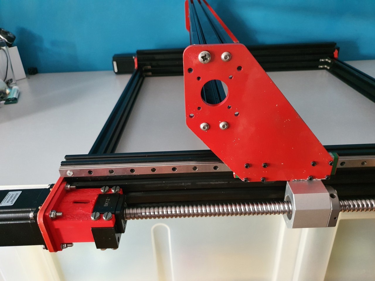
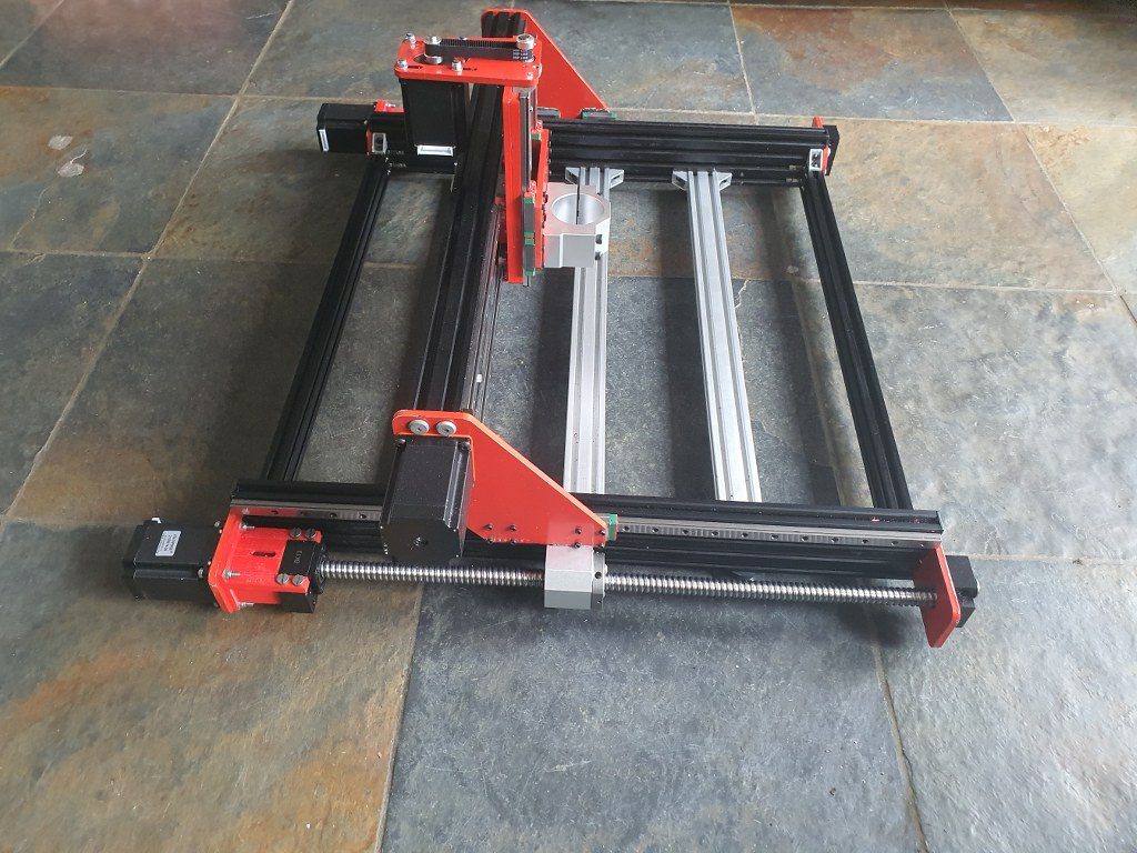
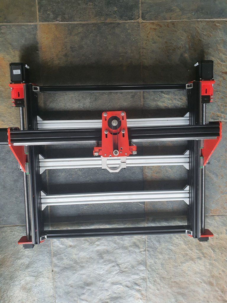
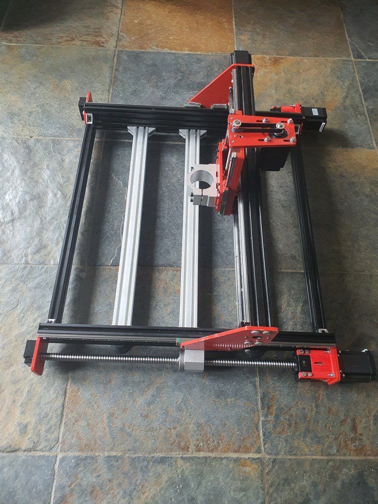
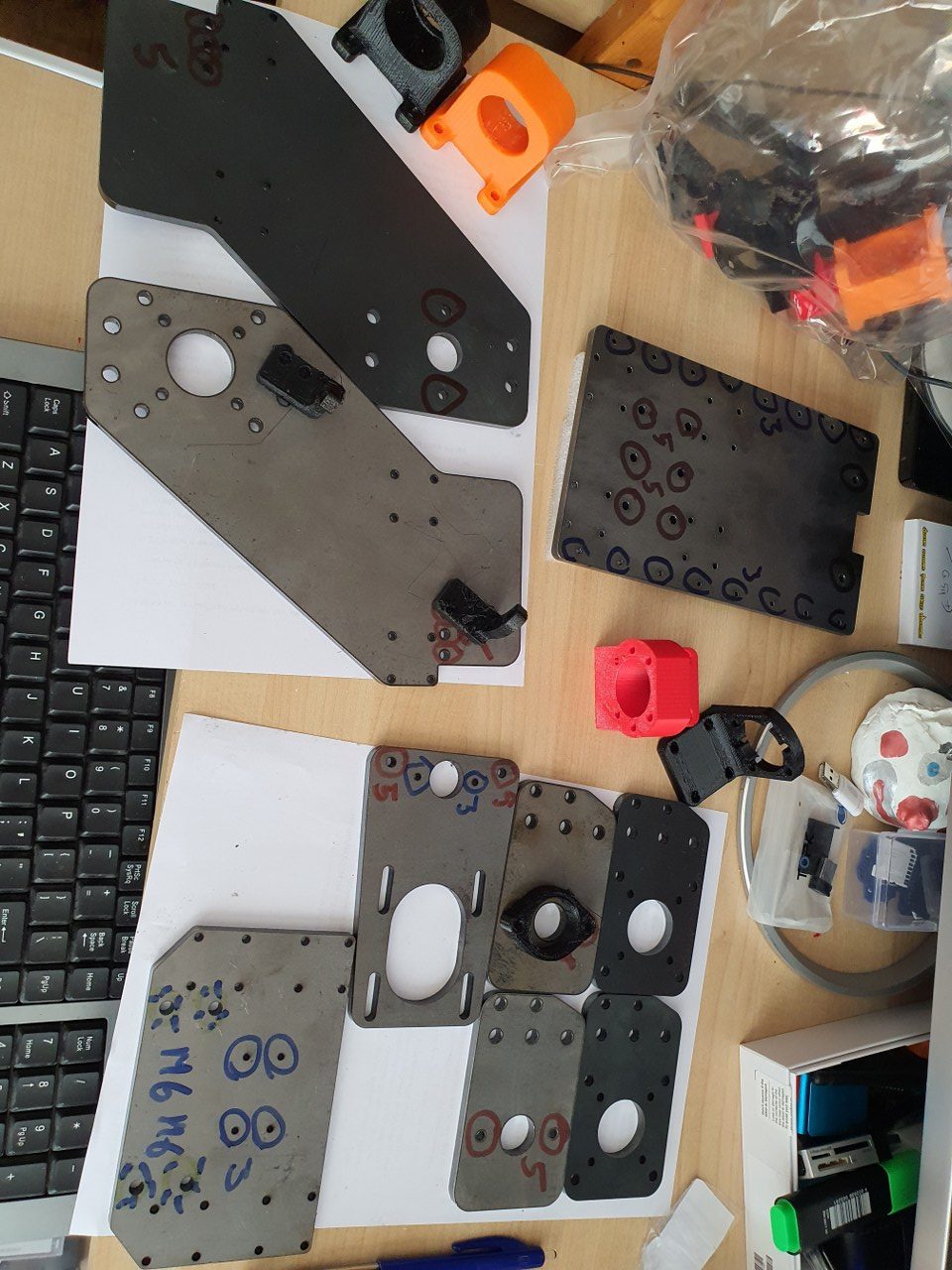
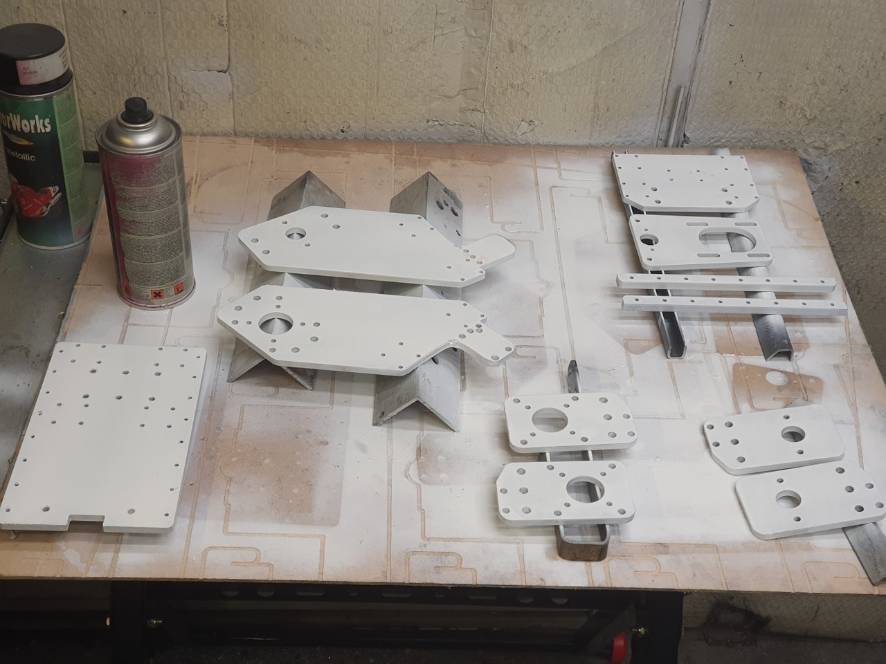
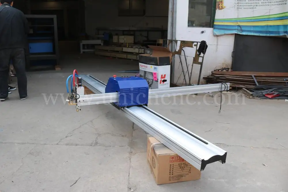


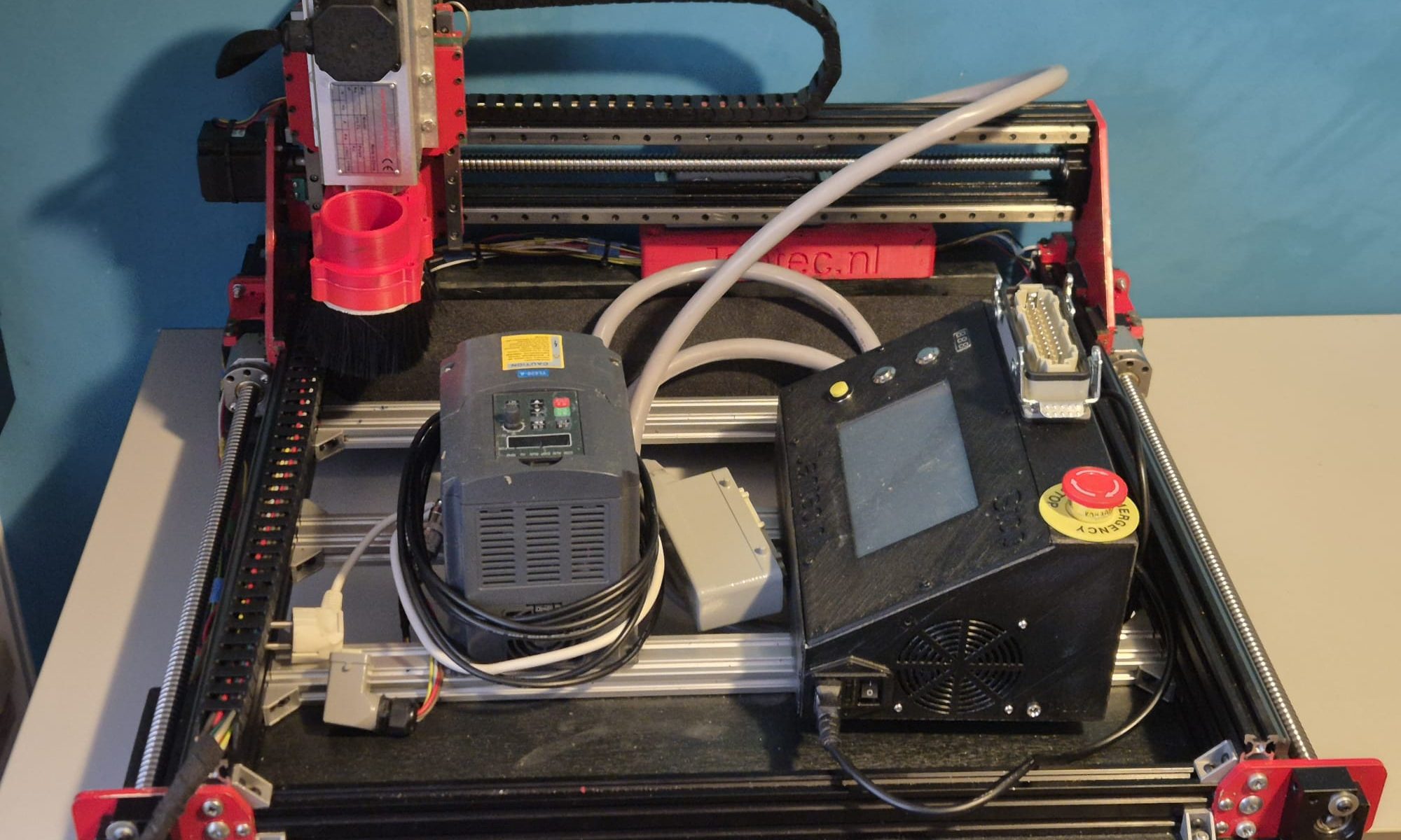
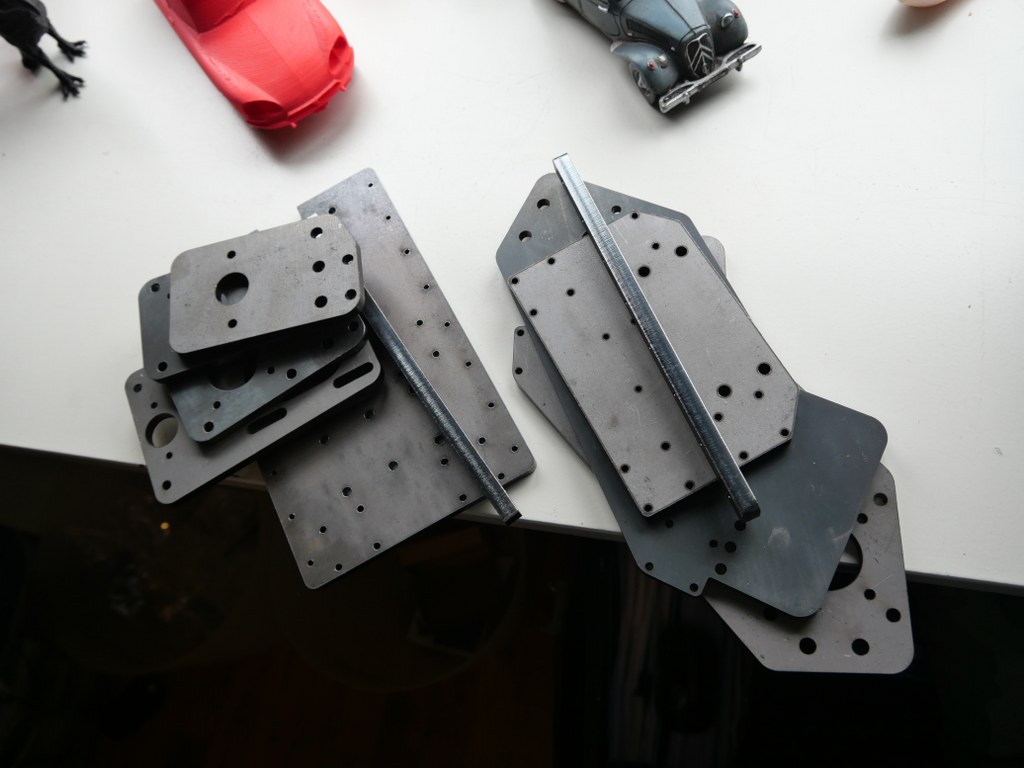
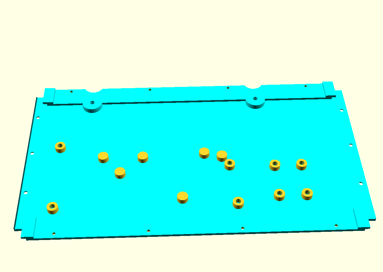
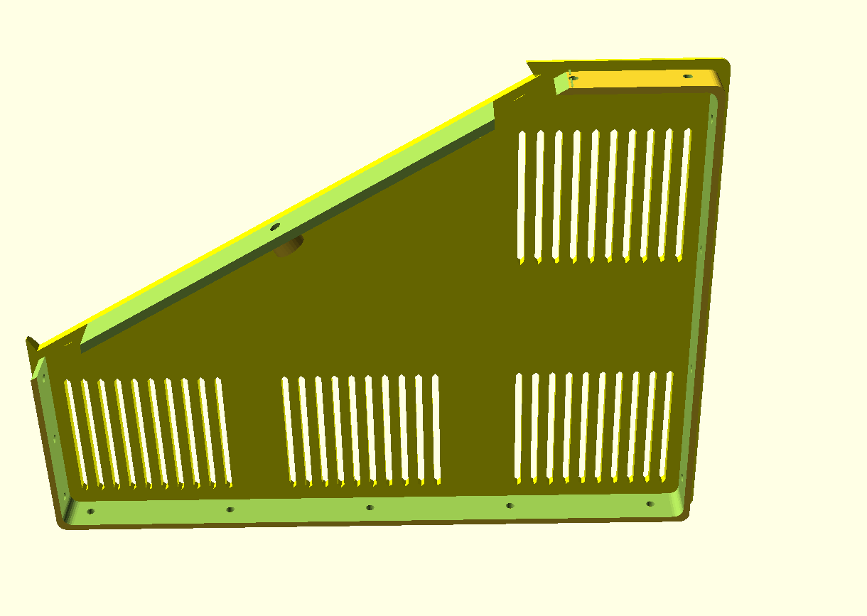
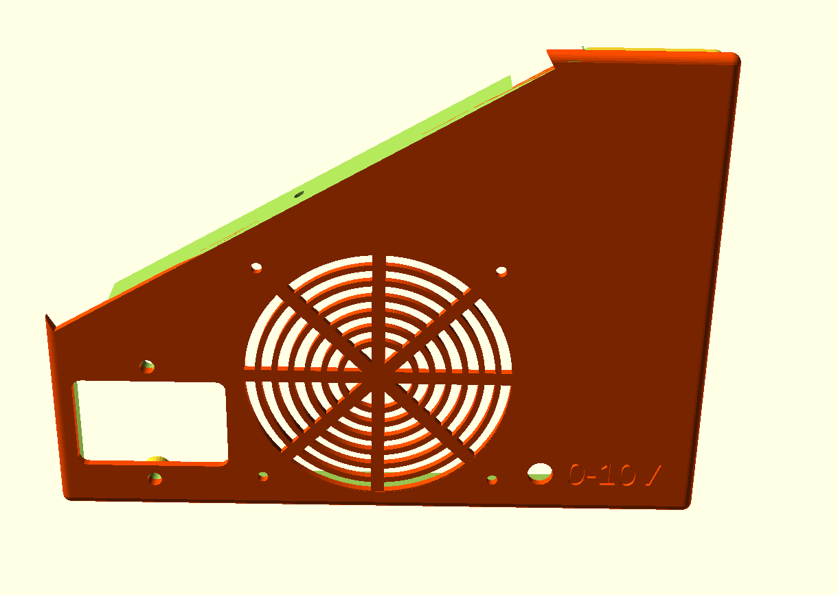
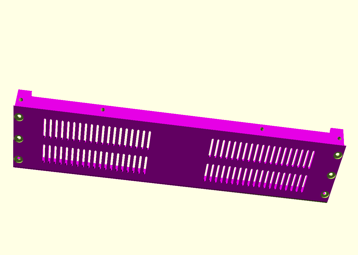
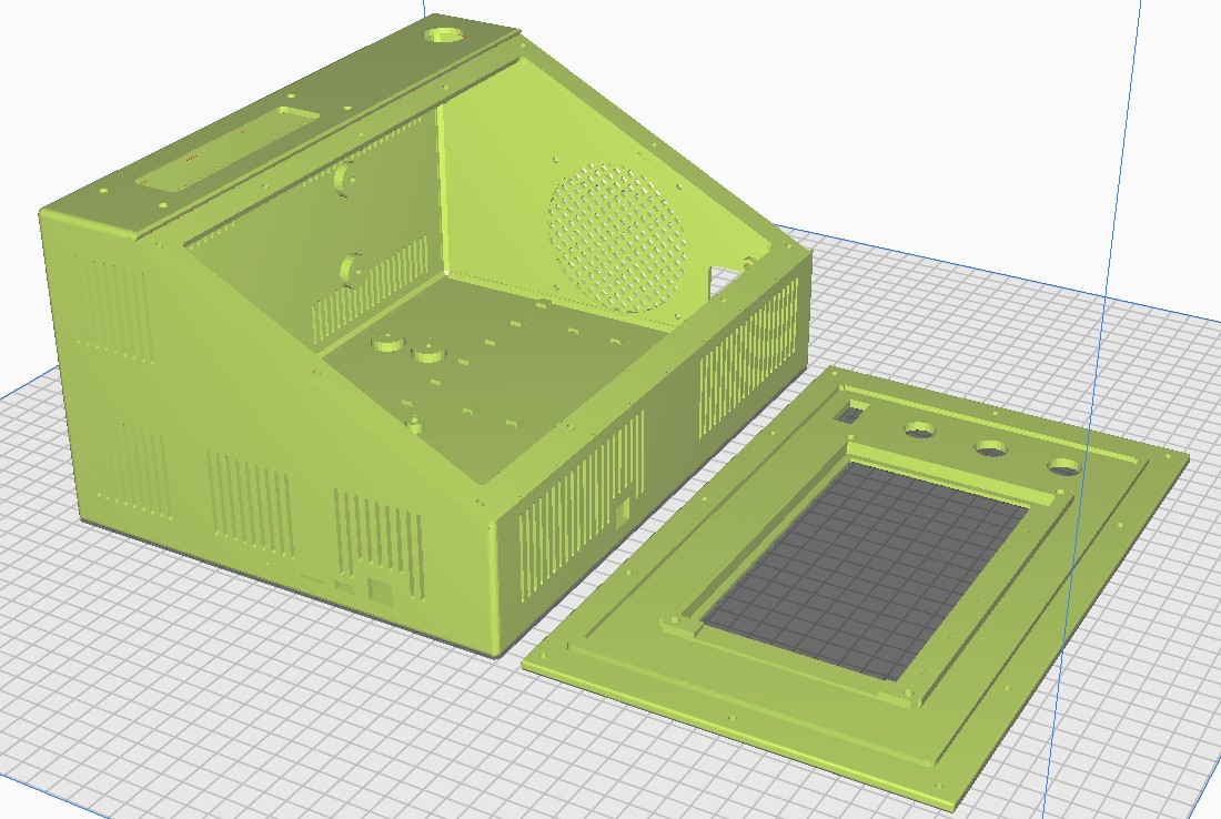
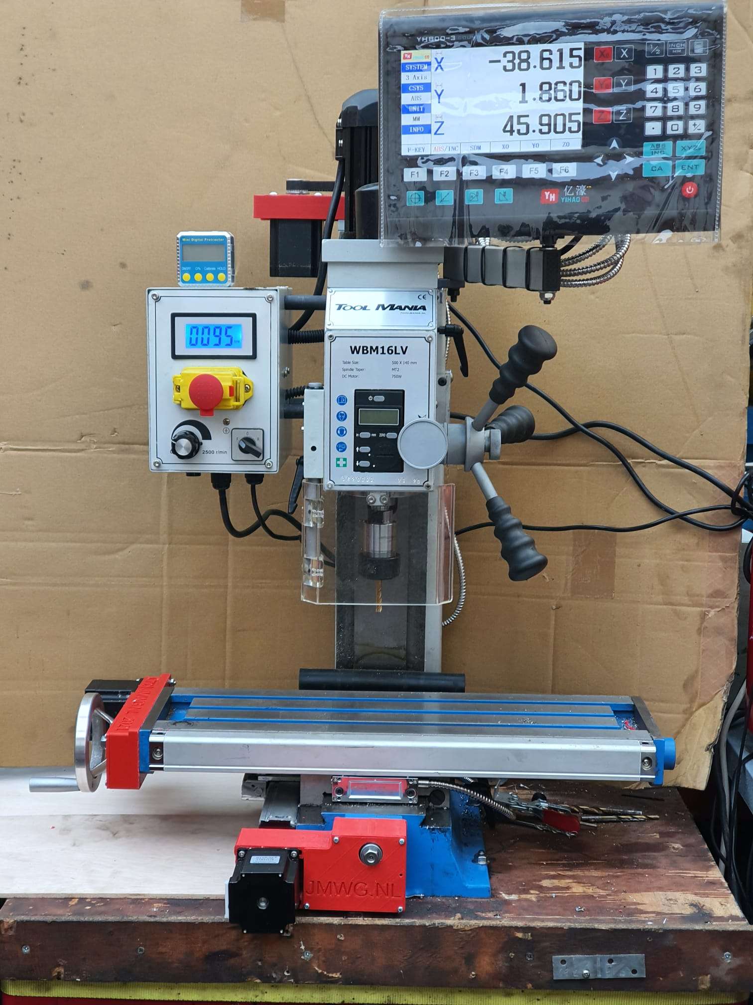
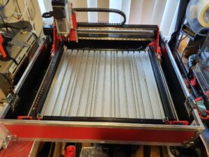
 and a simple GRBL 3- axis board that works very well. But- it would be nice to make a CNC machine that can really work with aluminium and possibly also with copper and brass. I have already done some research in the past about what sort of CNC machine would be right for my goals. And the IndyMill CNC macine was already on my mind for over half a year. So-last week I ordered the manual and the steel plates