
Since Corona was still around (May, 2021) , I had some time available to spend on other things than just work.
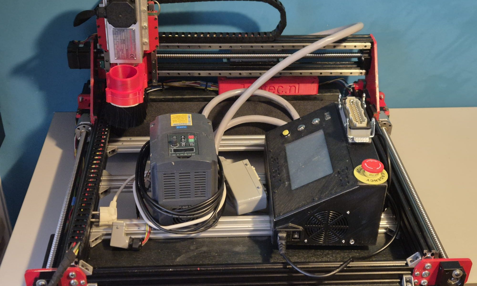
I already had an upgraded 3018 CNC-machine with a 0.5 kW spindle motor,
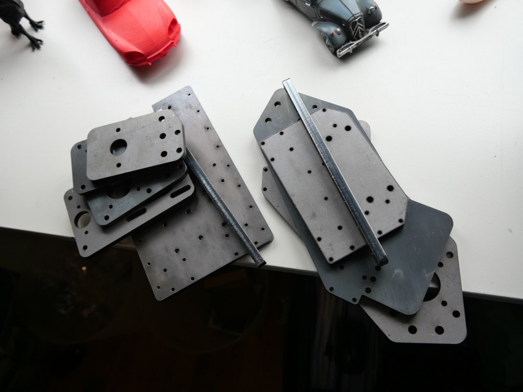
 and a simple GRBL 3- axis board that works very well. But- it would be nice to make a CNC machine that can really work with aluminium and possibly also with copper and brass. I have already done some research in the past about what sort of CNC machine would be right for my goals. And the IndyMill CNC macine was already on my mind for over half a year. So-last week I ordered the manual and the steel plates
 for the build and ordered some other parts from Ali. I also have quite a lot of parts on stock, from my 3d printer supplies. The Nema23- motors and the extrusion, motherboard, drivers, power supply, switches and probes are already available.
The required printed parts are being printed right now (early May-2021). I am printing all the upgraded STL’s, latest version as these are freely available on Thingiverse (just search for IndyMill) . And then you see the power of sharing: the design was already great, and with the upgrades it got even better. The upgraded versions of the mounts for the linear bearings are really a lot sturdier than the original design and the new endstop holders are very handy to have.
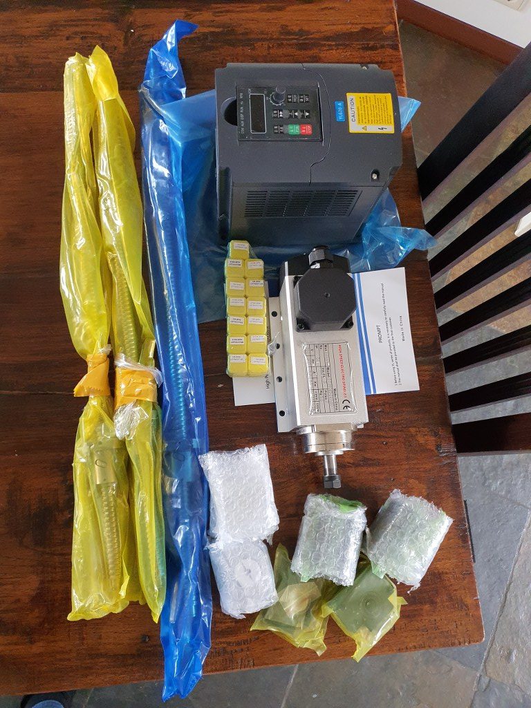
I roughly calculated the costs for building this machine and it was a lot cheaper than buying a similar CNC machine of this size. If you purchase wisely, the costs for all materials can be just under Euro 1000, if you follow the original BOM and including the 1.5 KW air-cooled spindle motor with regulator…
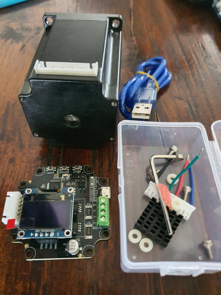
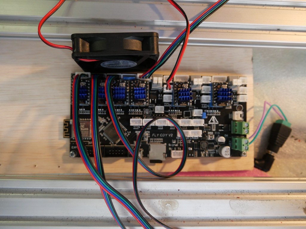
If you want to install another board than the standard Arduino UNO with the standard Arduino CNC shield, this can set you back an additional amount of 120 to 500 Euro’s. I use a FLY_CDY_V2 with Mellow’s original TMC2209 stepper drivers. DO NOT FORGET to set the switches on the underside of these steppers to ON if you want to use sensorless homing!
My add-ons to the original build:
- Currently I use a 10 Amps detachable 24V PSU, will become a 30 Amps one.
- Sesorless homing with the use of a FLY-CDY-V2 motherboard and TMC2209 stepper drivers. This works awesome but I moved on to add endstops and make a more stable and exchangeable setup.
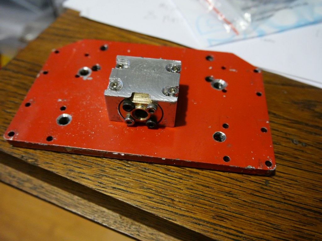
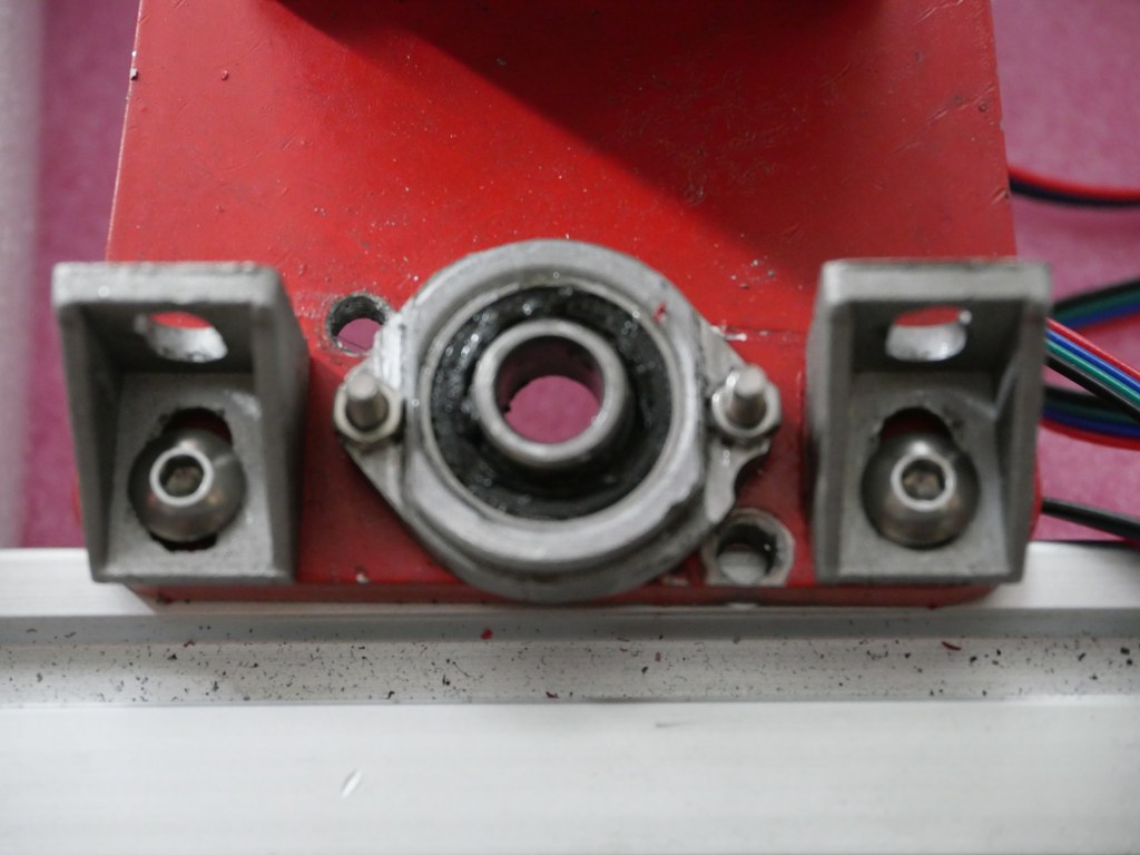
- Original mounts and usage of the ball bearing screw nut’s holder, and of the BK12 nd BF12 original bearing holders to keep the ball bearing screw from moving the wrong way.

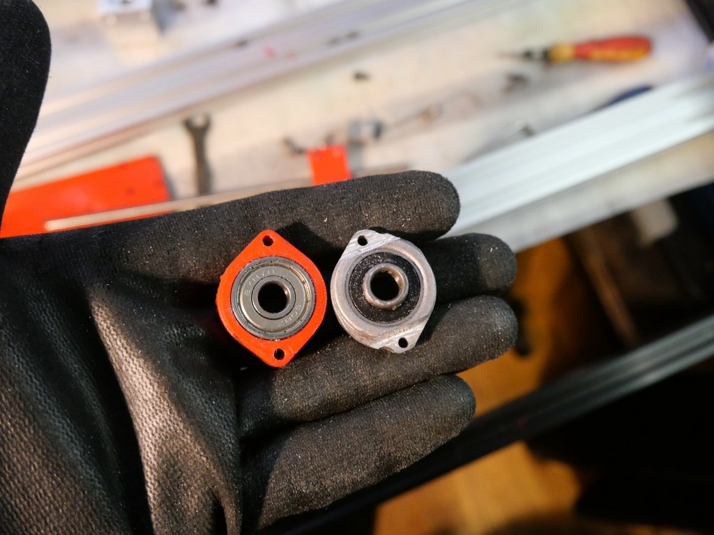
- Altered Z axis setup with a better nut holder, and a better top bearing
- .
- Closed loop NEMA23 stepper motors drivers MKS Servo57A V1.0 will be fitted to the rear of the steppers, still to be mounted but will conflict with sensorless homing

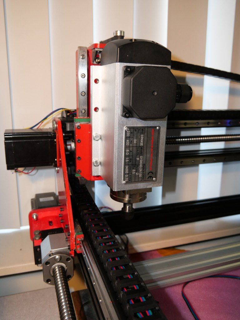
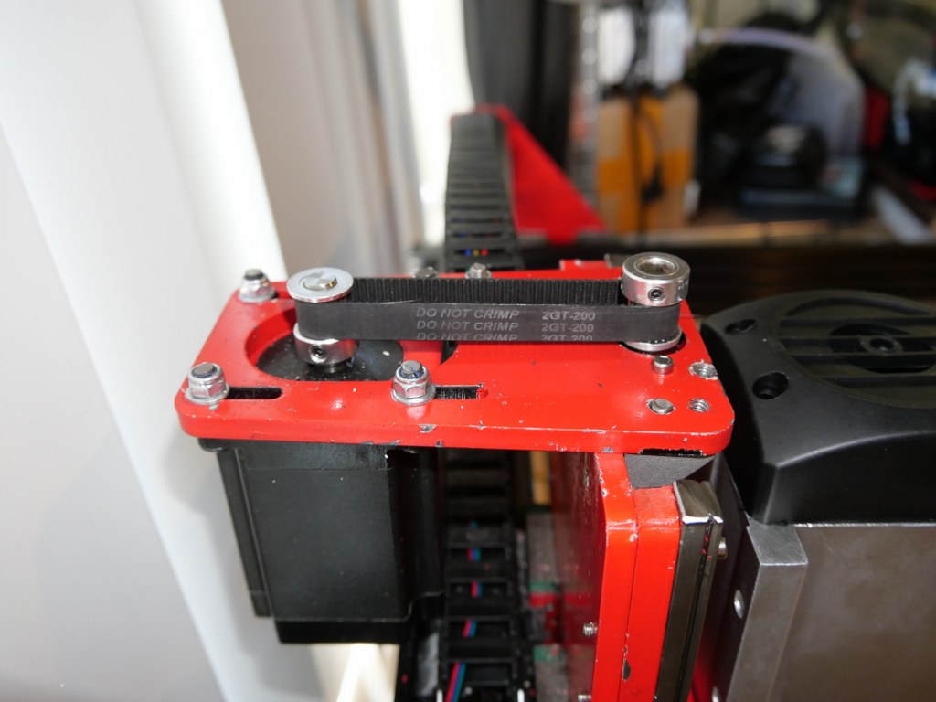
Nema 23 stepper with the Closed loop kit - 10 mm GT2 200mm belt between the Z motor and the Z-leadscrew with GT2 10mm wide 16-teethed wheels
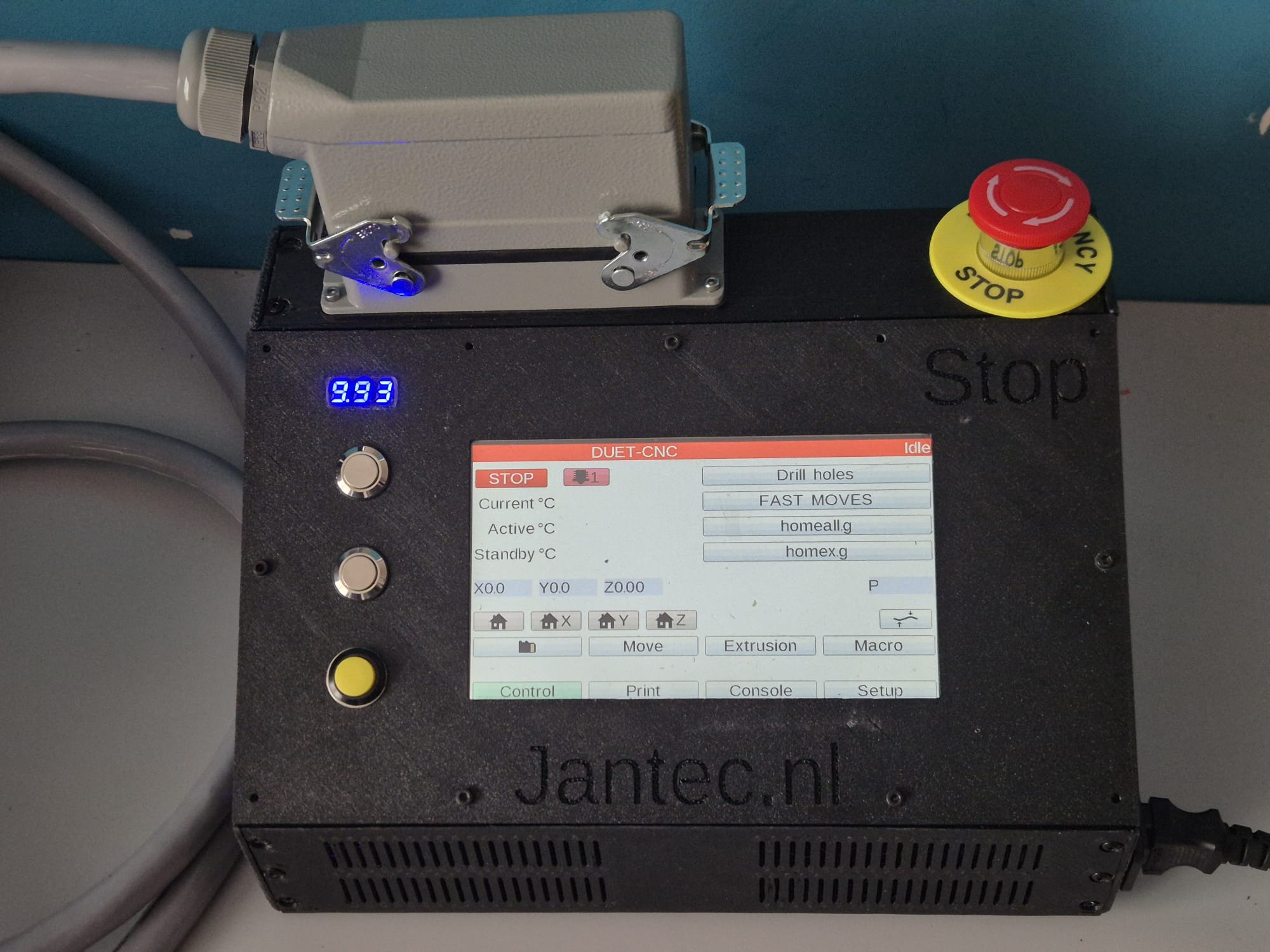
- Add a ‘CNC pendant’ manual control device.
- On the Duet support website a project is available to convert such a device to a serial interface, with a programmed Arduino (pro) mircro or -nano built-in the device:
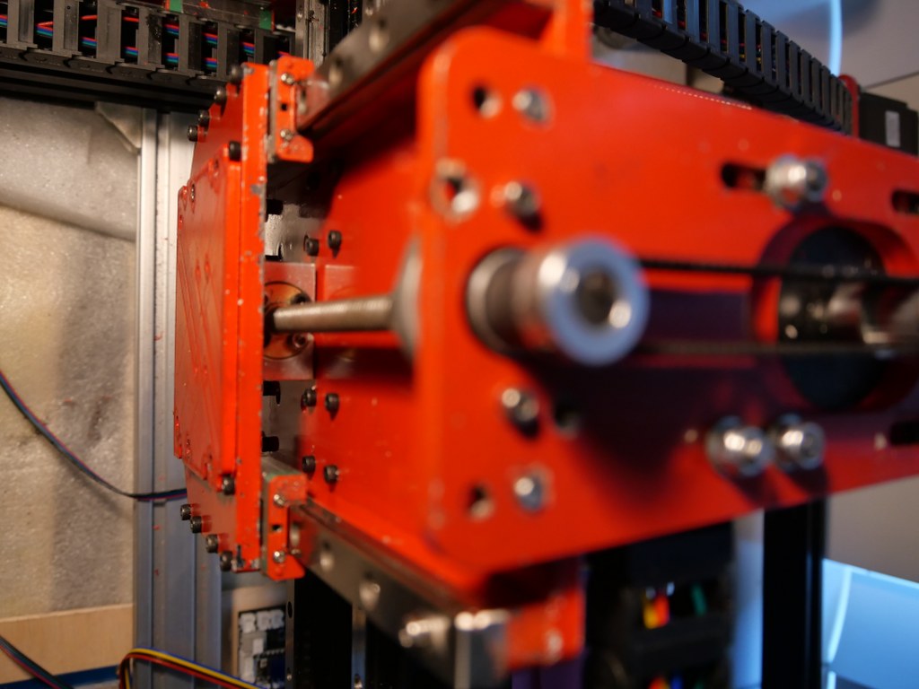
- Solid connection plate between the rear side of the upper and lower linear rails of the X-axis. Still to come.
- Piezo-probes on all axes’s start- en end positions, instead I first setup the FLY CDY V2 reprap board with TMC2209 and sensorless homing, and later with mechanical endstops.
- Coolant mist installation and fluid gathering-, pump, reservoir et cetera is ordered. Stll to be installed, and the pumps were not supplying sufficient pressure for the flood mist, have to look for another solution.
- Independantly driven (and independantly finetuned homing) Y-motors to prevent any possible problems between left and right. This works flawless with the FLY_CDU_V2 reprap setup but it took me quite some hours of finetuning to work with the 3.5 kilogram heavy spindle motor…
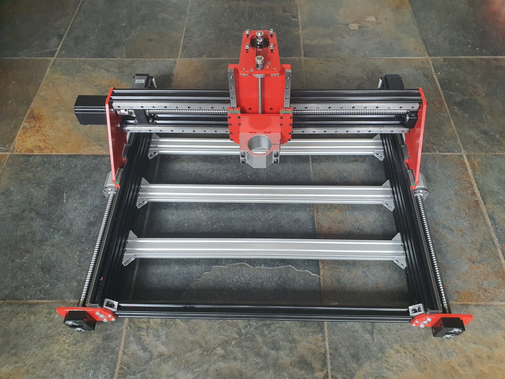
- 2080 profiles all around (also front and rear) with 4 extra-wide corner brackets underneath. I chose to implement this differently with 3 additional bottom connections and corner brackets, since I need the front of the frame to be low and give way to the spindle vacuum hose.
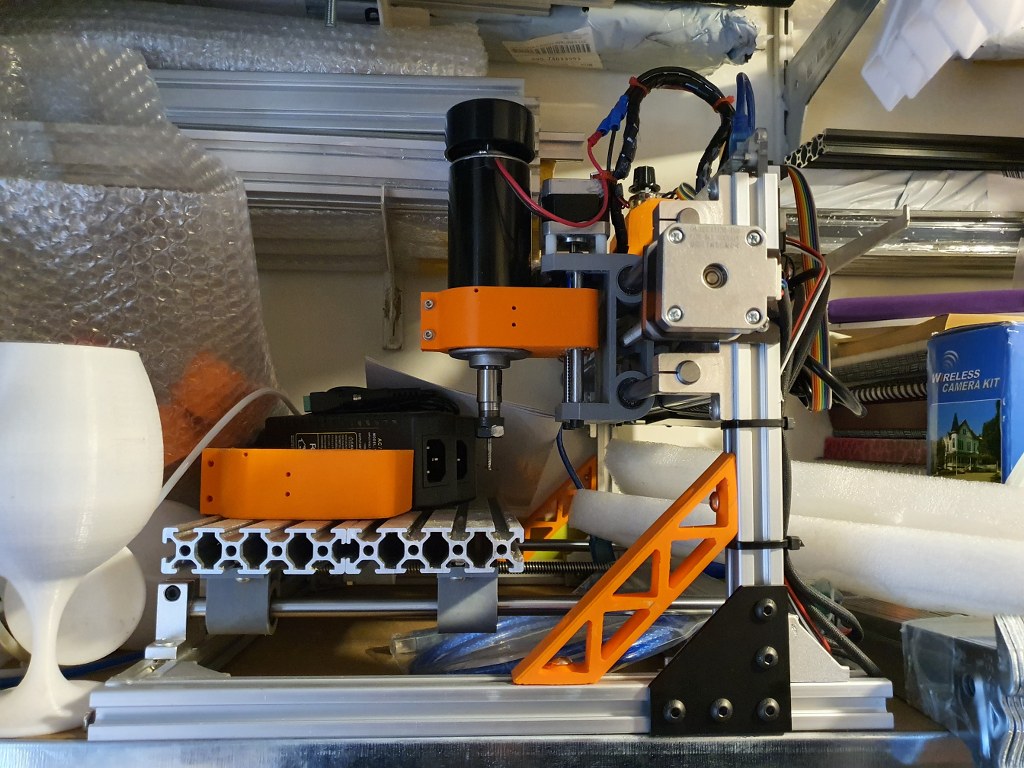
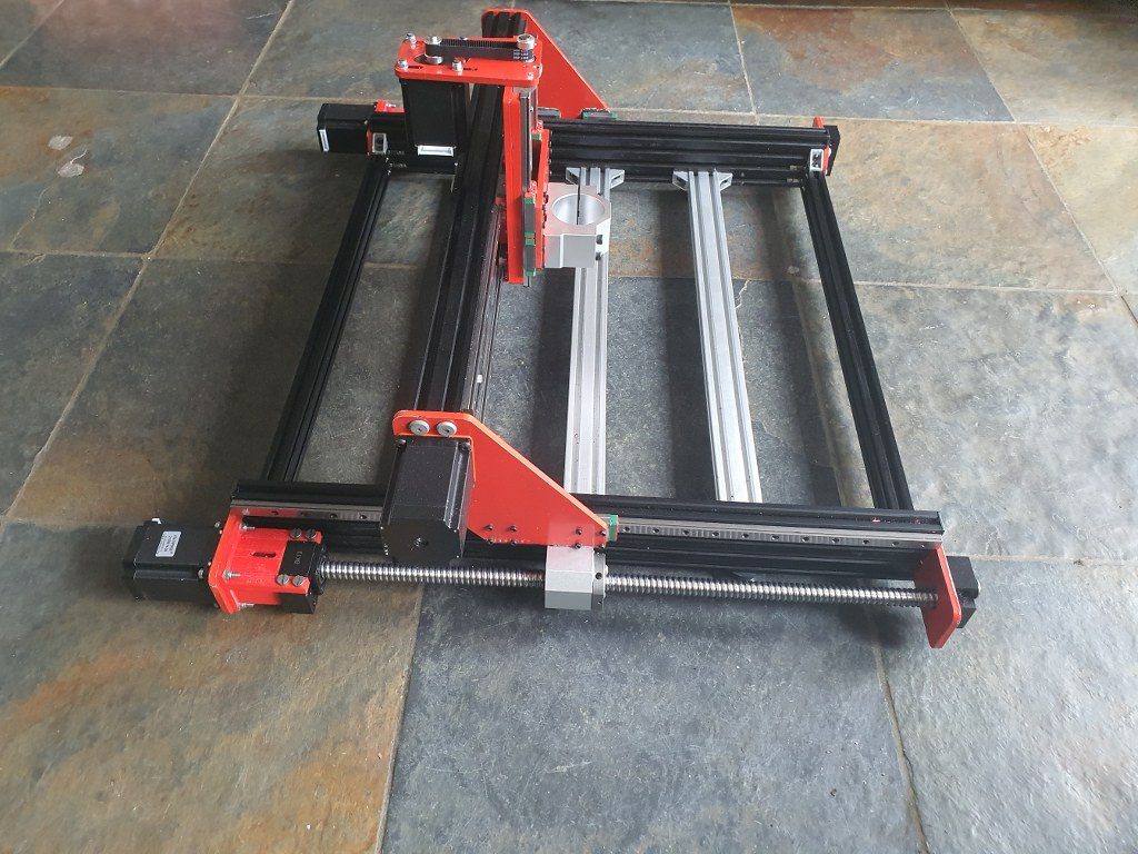
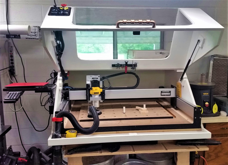
Amd – the frame as it is ready, but with the spindle holder of the 500 Watt motor. I will not use this motor after all for this build– - Smart enclosure with Scheppach vacuum cleaner connection like this example from https://www.shophacks.com/cncenclosure.html#/ THIS IS REALLY NEEDED!

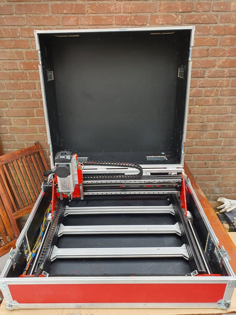
My solution for an enclosure ia a 84x78x45 cm flightcase - Protecting guards for all leadscrews and linear rails (ordered in China)
- Later if possible: Wheels on the rear or on 1 side and a handle on the front (or other side) to stow and store the machine easier
- Easily detachable control unit(s) with solid connectors
I started with a FLY_CDY-V2 reprap board to experiment with reprap CNC and the webinterface that has been developed for this setup.
 This is achieved with smart dual homing of the dual Y axes, and gives me a lot more control on the machine. It is also already possible to just send GRBL-based Gcode to the USB port of the machine and use the reprap FLY board simply as gcode-interpreter to steer the machine. But for now I use the webinterface
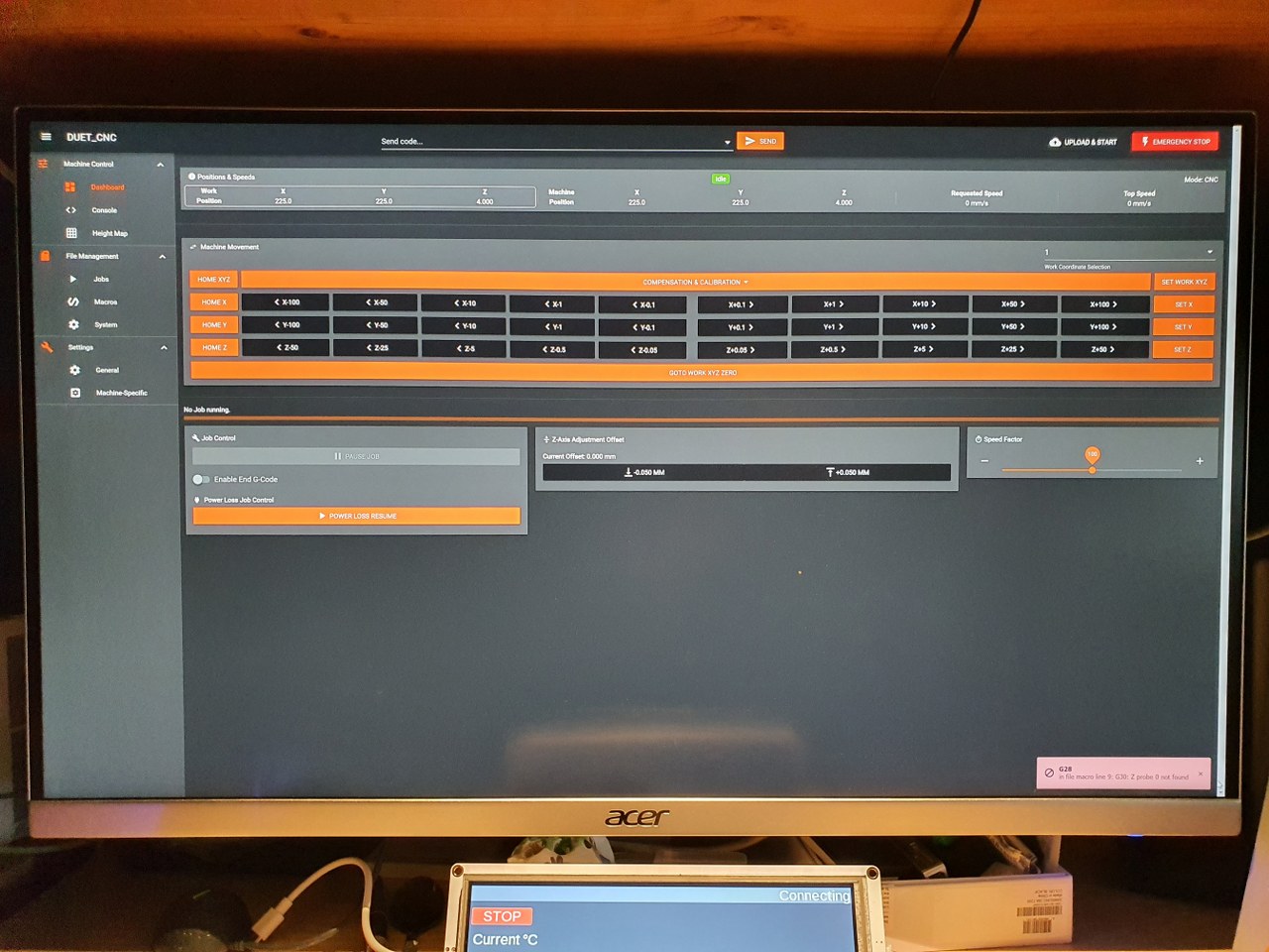 to upload and run any gcode.nc CNC file, which works perfect!
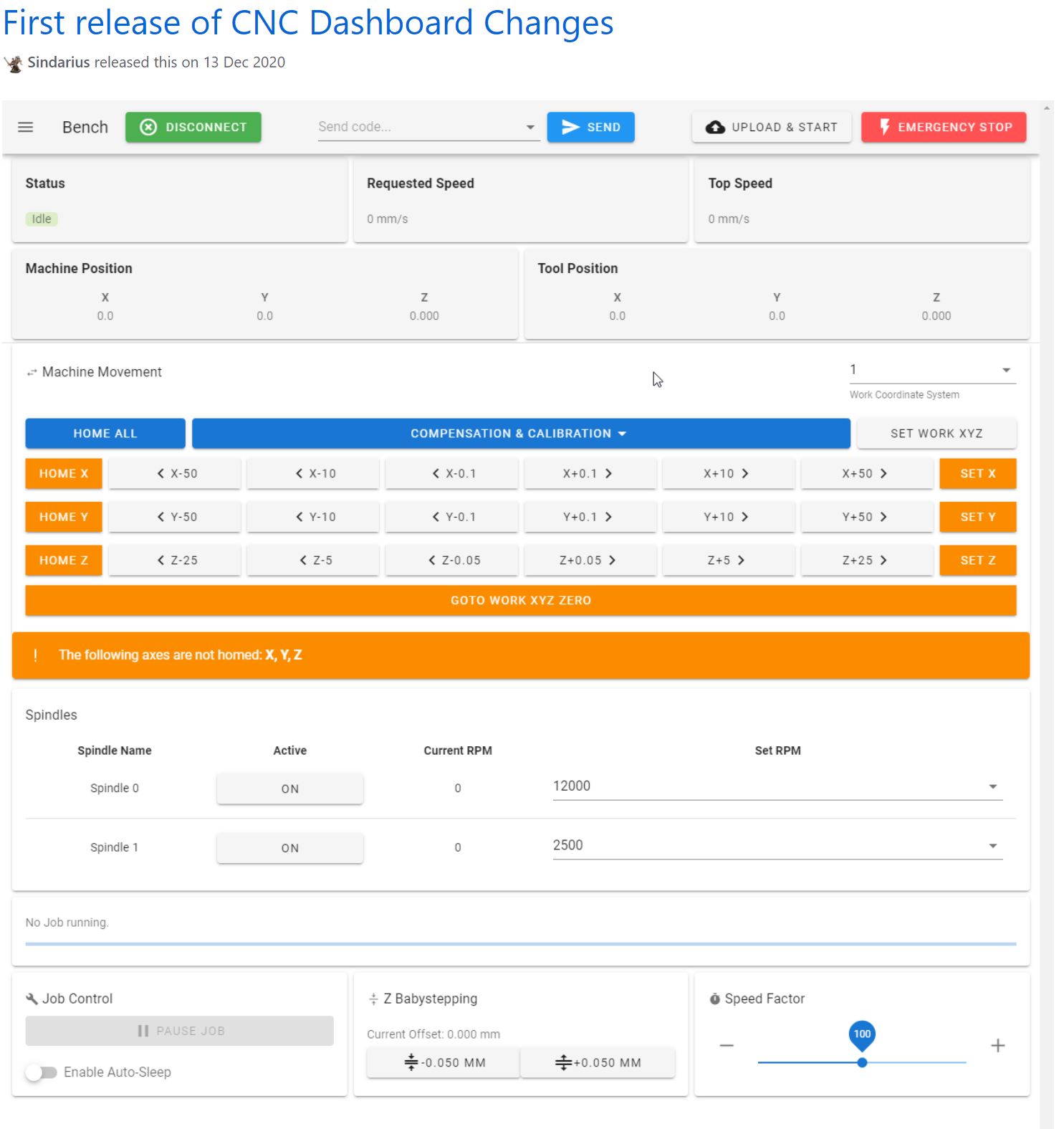
Picture of the CNC-adapted and already available webinterface for reprap, especially tailored for CNC (by Sindarius, work ongoing):
Pictures are already published about this build!