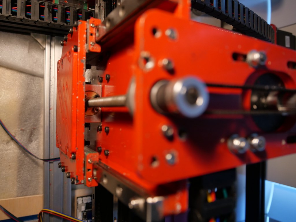
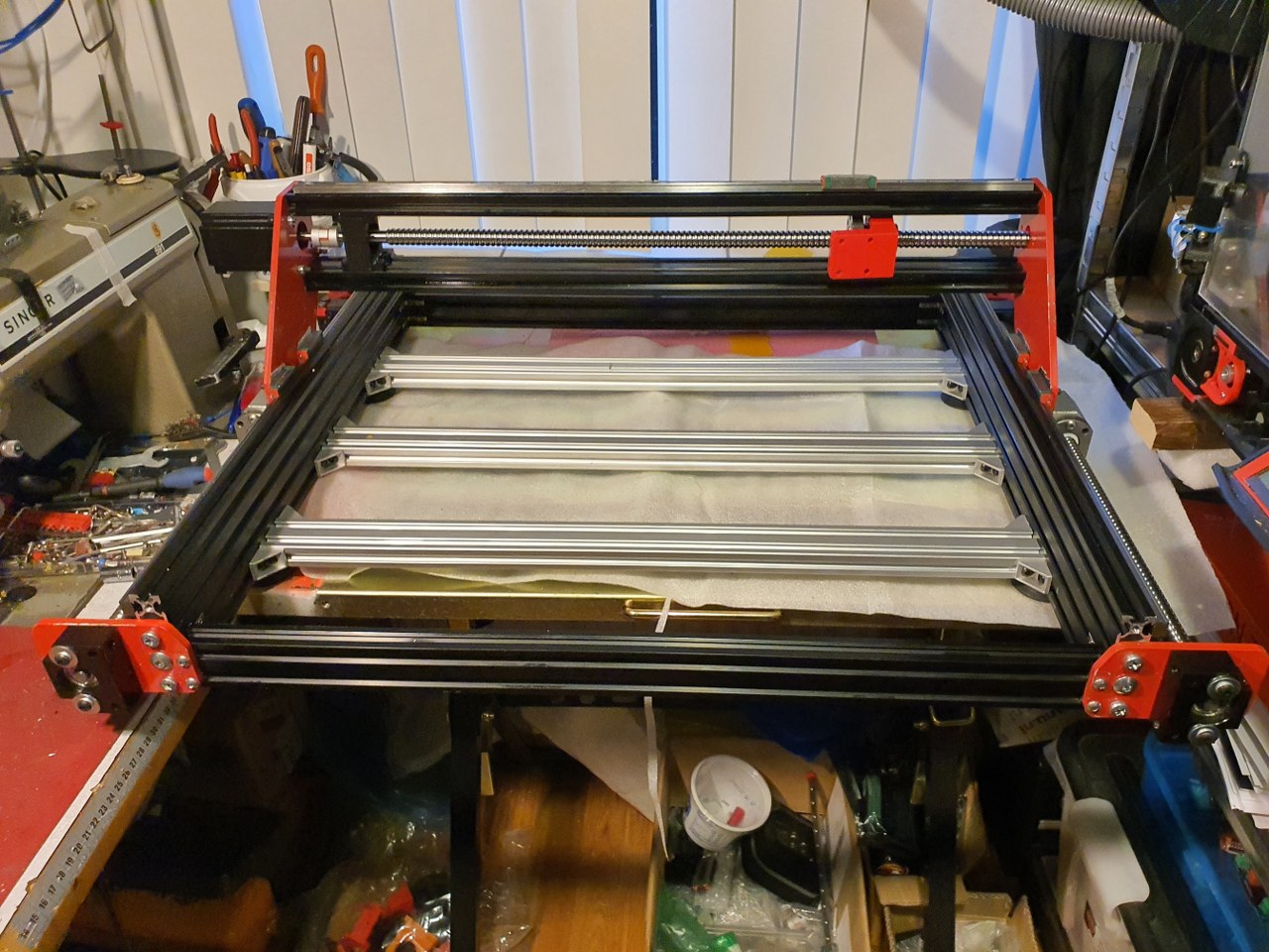
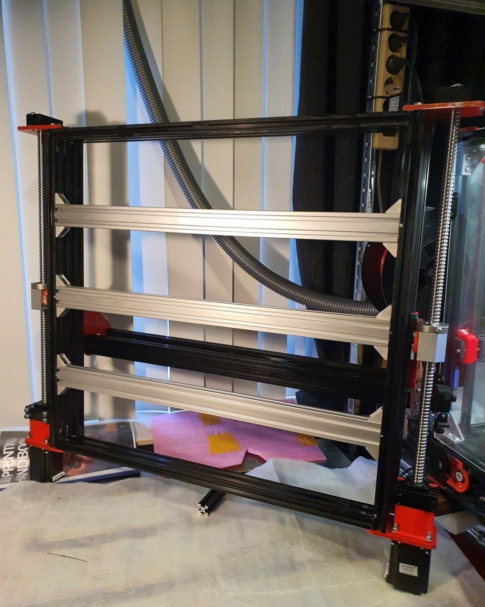
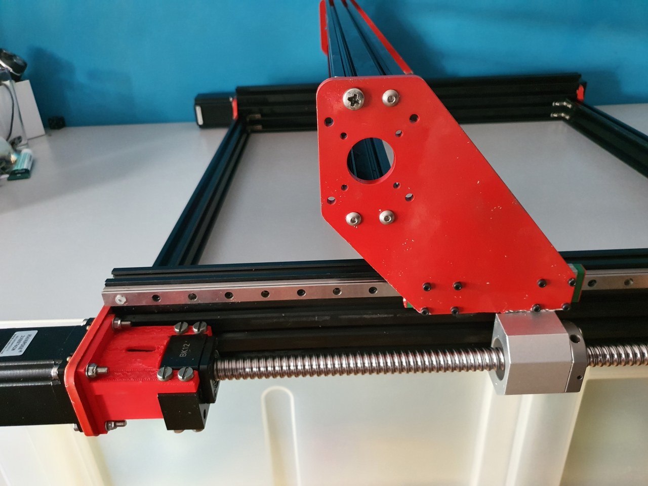
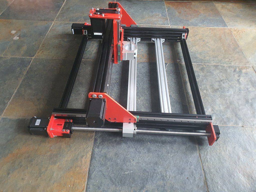
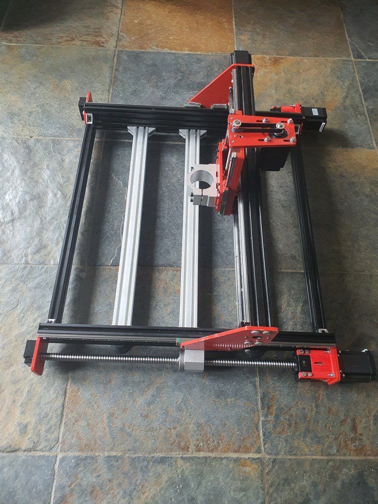
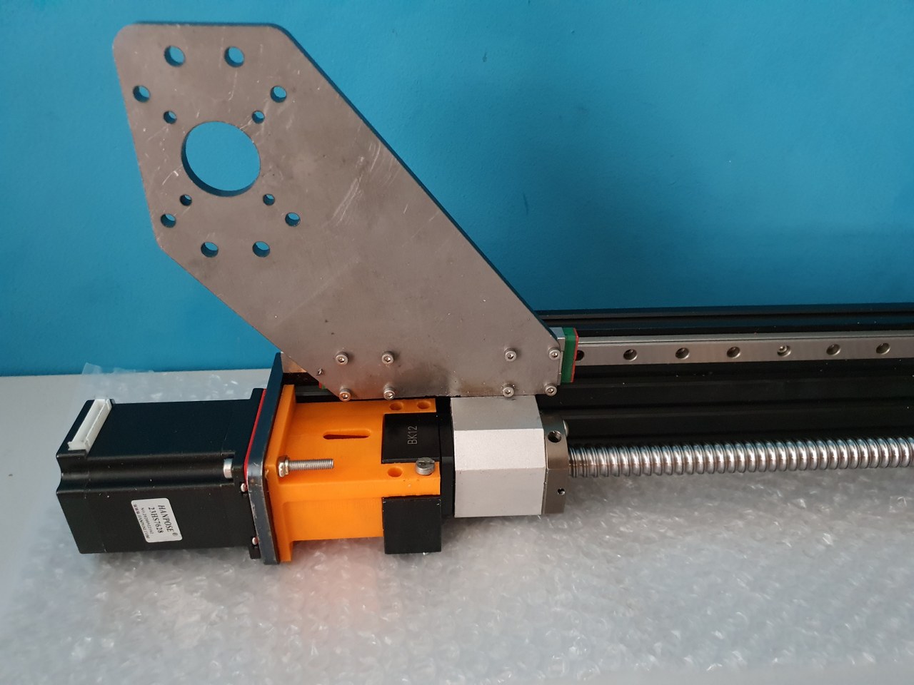
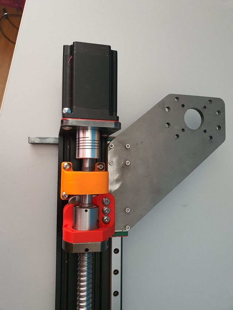
On top you see the X-axis, still without mounted linear rails but the 1605 screw is loosely mounted. The red connecting piece for the Z-axis is on the ball bearing nut. the black part on the left between the 2 lengths of 2040 aluminium extrusions is the (anti-) push/pull bearing block that holds an axial (up/down/left/right) and a radial (left/right) bearing but can not withstand any real big lateral force (L-R)
Under construction-still trying to find out how to do this.
I intend to use the same method as with the Y-axes so drop the 3d printed parts as much as possible and re-use the available bearing blocks and nut holder.
For the red nut holder I only need to make a flat extension plate to connect the nut holder to the Z-plate.
For the end bearing block BF12 to the right, this is no problem. I can mount it easily on the sideplate’s outside.
The push/pull bearing block BK12 is more difficult to re-use, I will try and find a small enough connection block that is 3d printable to shape the BK12 in, and still fits in between the 2 horizontal aluminium profiles that shape the X-axis. It will be very tight so I might have to make something myself, possibly I will just mount the BK12 on a in-between piece of 2040 and first I can mill a hole in the center of the 2040 piece so the end of the 1605 ball bearing screw can gain access to the BK12… Or something like this, will try and report how it goes later!
2021-5-24: Found a possible solution with an adaption of the same Nema23 to BK12 housing as is used for the Y axis. I am printing this fast with PLA on the Ender pro, will cut off some flesh of the NEMA23 top and bottom flange and will then fit this between the 2 lengths of 2040 extrusions and see how it works! The screw holes will have to be saved, but 4cm in the center will be removed, some 4 mm wide om both top and bottom.
Today I made the last solution fit the X axis and got all related components to fit the X-axis. During this I found that the left bottom ball bearing slider cannot move along the BK12 block.. So, I machined some material from this block’s side bottom. That doesn’t hurt but it does impact my planning a bit. And- during the process I destroyed a piece of the PETG BK12 holder that connects the BK12 bearing block to the stepper motor and the in-between side plate. I already directly printed a new ABS part to replace the PETG and wished I had started with ABS like I dit with the Y-axes. But- look at the bright side: Now all 3d printed parts will be ABS red: like the steel plates!
You must know that I elaborated quite a lot on how to print the Neam to BK12 couplers and fount that it is not good to print these withh the face to the Nema23 motor DOWN. Instead- I printed them flat, with the side that faces the stepper motor to any side but down or up. This gives great strength to the 2 pieces that carry the mounting holes for the BK12 bearing so they won’t break during use.
And I found that ABS in my case (both ABS red and PETG vblack are Sunlu products) works better for this build because the PEG breaks under strain and ABS flexes a little but does nor break..
In this post, you can see how I changed the original Indymill to more rigidity by using the original 1605 aluminium nut holders for the 1605 ball bearing screws of the Y axis, and how I made use of the BK12 and BF12 ball bearing blocks instead of the 3d printed parts like in the original build.
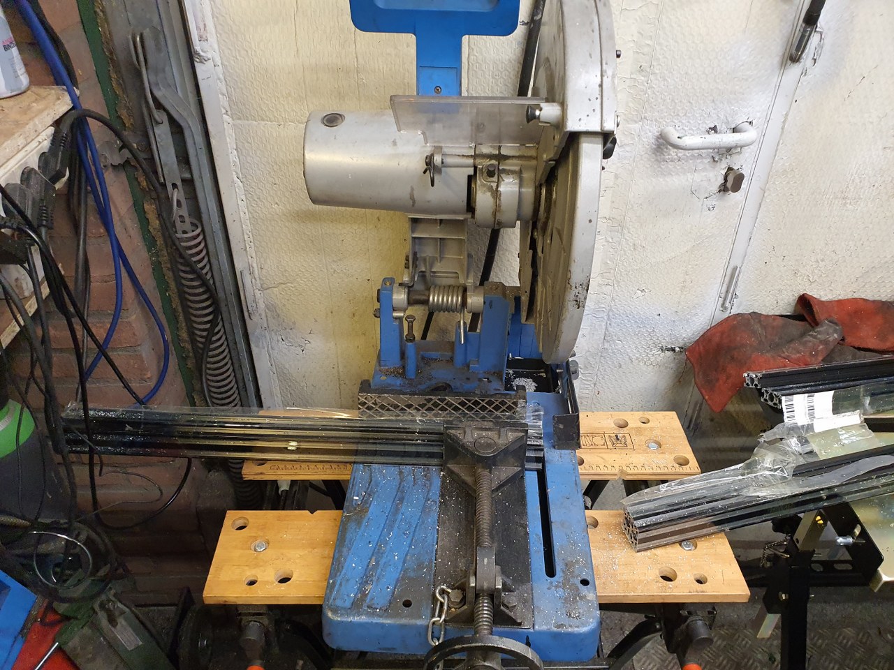
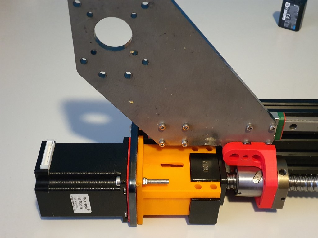
Yesterday 2021 05 22 I cut the aluminium profiles that are required for the frame of the Indymill. My metalsaw is set at the perfect 90 degrees angle that you need for these aluminium extrusionsToday I put the frame parts together, based on the changes that I made to the ball screw holder block and to the screw bearings and -holders. And- overnight I spraypainted all metal parts red. Used just what was lying around.Left side, left is the Nema23 motor, and the BK12 bearing block is now connected to the engine plate with an ABS sideways printed connecting piece. ( I found the PETG printed parts I made earlier to break on the sleeve at the left when applying force, so I went for ABS and I printed it as you see here with supports to give strenghth for the bolts and nuts.) To the right, the aluminium nut holder is placed. This has been milled down and new screw holes were made in the holder and plate to connect it to the plate (see the text later in this post)same treatment on the right hand sideOverview of the RH side with the end bearing and -block, connected to the front plate bearing holder. I milled additional holes in the bearing blocks (front L&R) to (re-) use the tapped M5 holes that are already in the red connecting plate
When building the frame, make sure that you do not initially screw anything tight. Follow the steps that apply to any build:
Make the footprint square by measuring either with a good 90 degrees angled measuring hook OR measure the diagonals against each other and make them alike. Then, tighten all corner screws .
Re-measure the footprint’s left against right length and also front/rear length. If there is any difference here, a) take everything apart and b) make sure you have equal sizes for your build where this is required. OR, if you have a non-standard build, make sure you build according to specs sizes. The, do 1. again.
For a lineair rail: use a ruler that is specifically made for your type of rail You can 3d print one or buy two aluminium ones. ALWAYS use at least 2 rulers! With the rulers in place at 20% from left and 20% from the right, after you have installed the rail loosely with the screw in the nuts, tighten the screw a bit but not too stiff.. We will get back to these screws at a later stage.
Put the connecting piece on the motor’s axle (8mm side) and tighten this well. Preferably, use some loctite on the axle but don’t overdo it. Be aware that you need to testfit the BK12 first. make sure that the connecting piece almost touches the BK12’s nut!
Put the stepper motor and the BK12 connector together, using the 3d printed thin NEMA23 adapter plate between motor and steel plate. Do not yet tighten this too much.
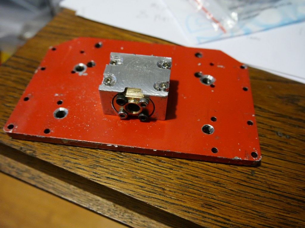
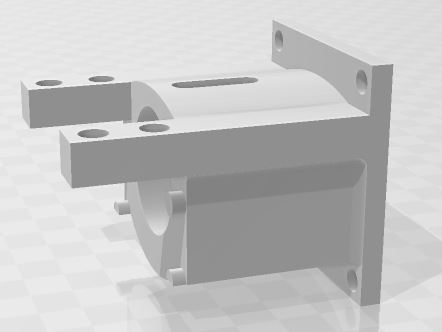
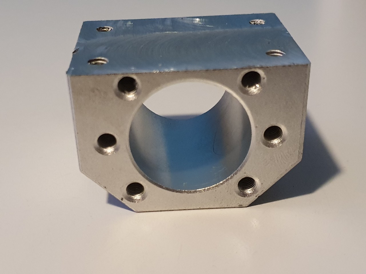
Make an original aluminium 1605 nut holder block shorter to fit exactly. See the picture.
Fit the aluminium nut holder block including the entire assembly of the 600 mm long 1605 ball bearing screw on the machine, and superglue the block in the correct position. Let it dry so it won/t come off. Demount verything except the steel sideplate and the glued aluminium nut holder.
clamp the nut holder to the steel plate with a grip vice, just to make sure it all keeps together.
Drill 3 new 4mm holes through the steel plate’s lower part , drill through the aluminium block as far as possible. 2 holes on the lower side and 1 just between 2 of the top 3 holes, NOT where the existing hole of the aluminium nut holder block exists.
Get the nut holder block loose, if it has not already come off.
Tap M5 in the holes of the nut holder block. You will have come through the big center hole (for the nut) with 2 holes, make sure this gets cleaned up on the inside.
Drill the new holes in the sideplates with 5.5 mm drill (to give you mounting clearance)
Place the sideplate on the 2 bearing blocks of the linear rail with 4 outer M3 x8 (or x10) screws.
Put everything loosely together
Mill an end baring block to fit the 1605 ‘s screw end at the front an mount this at the exact center of the small front plate.
Now, connect your nema 23 engine to a motor steering device so you can test the setup. First, turn the screw by hand and it should run smooth.
Since you want to have an even height of the side plates, do not alter these unless it needs to be done on both sides equally.
Your fixation point is the only non-movable position, at the rear of the frame.
Move the carriage to the rear and now, see if you have slack on the M3 screws of the slide bearings AND on of the 3x M5 screw the rear of the aluminium nut holder. If so, first tighten the M3 screws. Then tighten the M5 screws. If not, loosen ALL of the linear rails screws ans move the rail a little. If this is possible, tighten the M3 screws of the linear rail’s bearing blocks. Then, try to get as much clearance on the linear rail’s movement up/down as you can and tighten the 3x M5 screws of the nut holder block.
Now, tighten 1 screw only of the linear rail, at the position above the nut holder.
Move the carriage entirely forward position.
Tighten the linear rail’s M3 screw that is exactly in position above the nut holder (of the ball bearing screw)
Now, tighten all screws of the linear rail.
You’re done!
Check the other side and if the linear rail’s height differs from the other side, the only thing to do is to start over again, where your slack is in the 5.5 mm holes of the steel plate’s screw holes for the nut block. If you play with this, and then adjust the linear rail’s height, you can get it all even. At least’eventually I got mine right but it took some time. Have fun!
Things to bear in mind: You don’t want anything out of parallel like a linear rail that is uneven to the aluminium profile on which it is mounted or a ball bearing screw that gets under tension. There is also another way to see what is happening while you are tweaking the hardware/frame: take the front bearing off and see what happens to the end of your ball bearing screw in the hole up front when you move the carriage. It can tell you much about what is happening… It should always stay perfectly centered but I’ve seen it up, down and all other directions.. -)
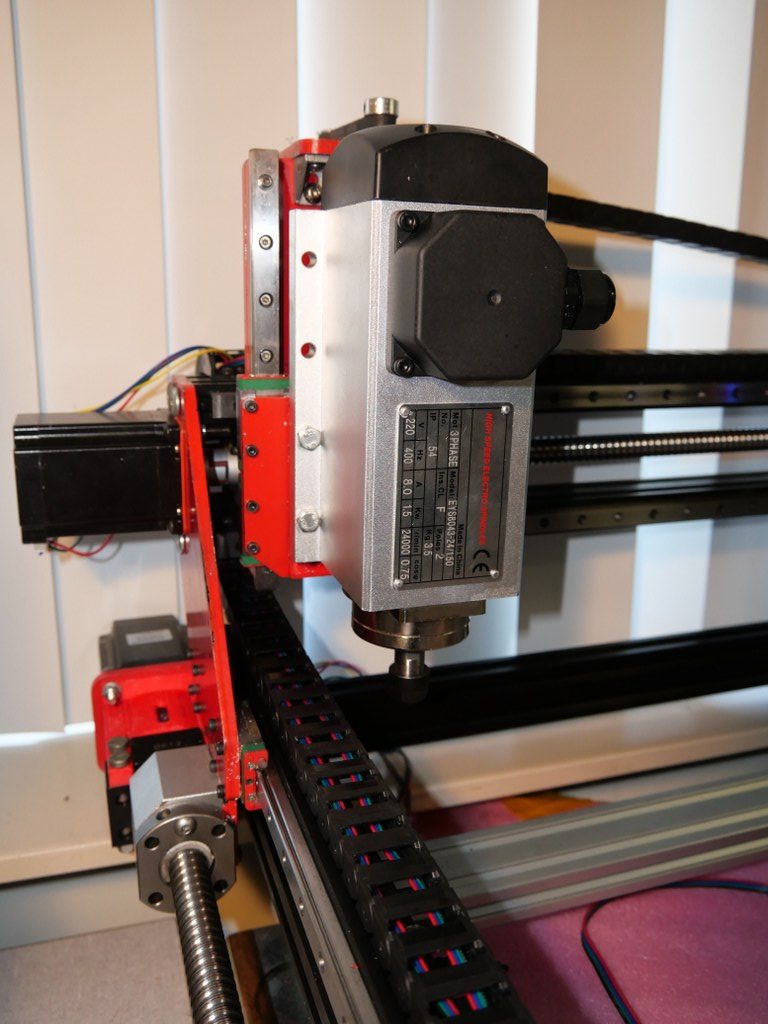
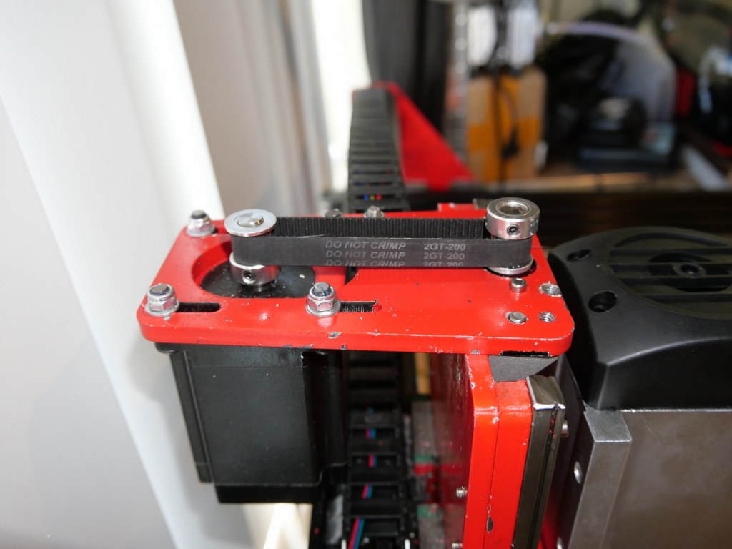
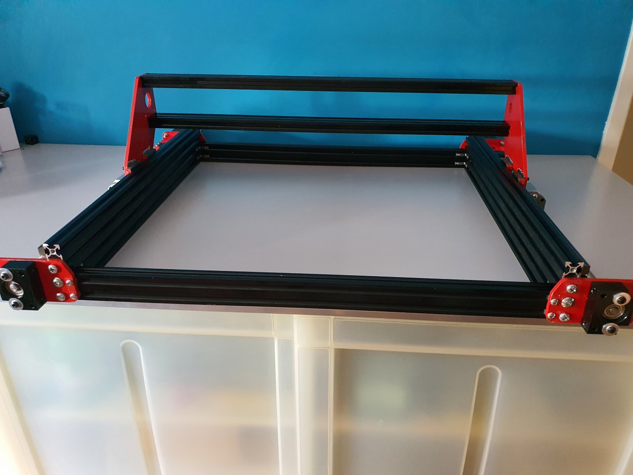
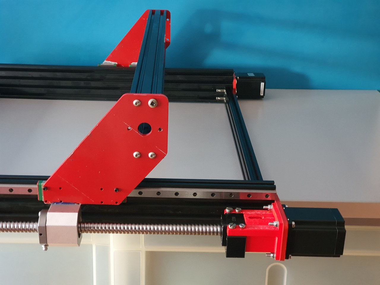
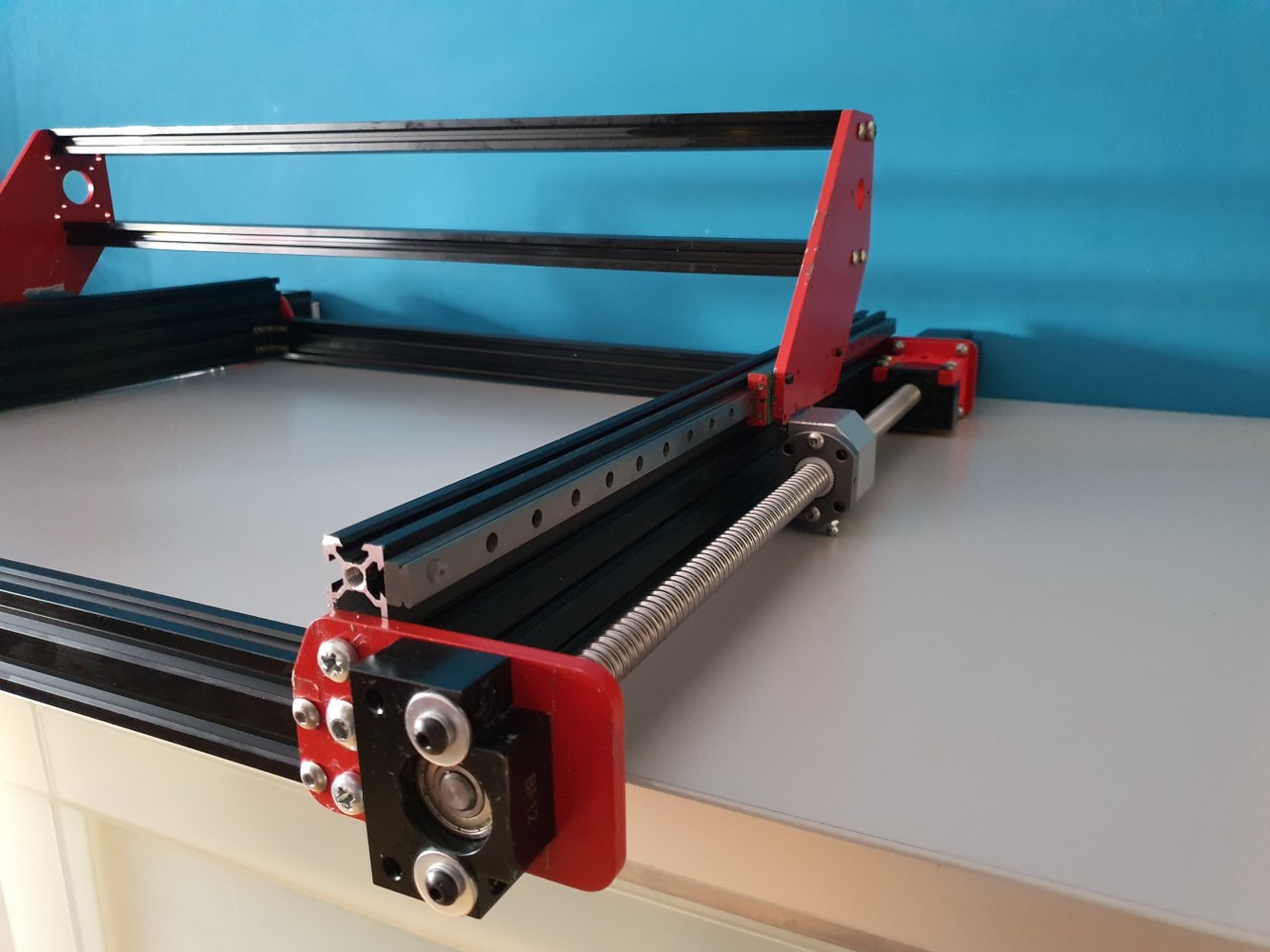
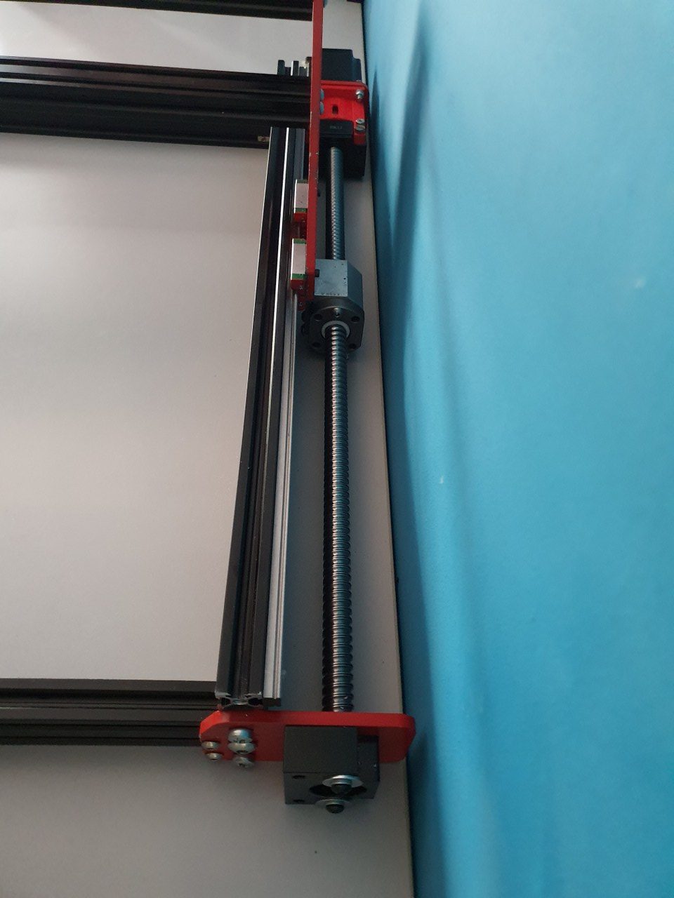
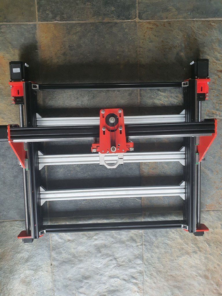
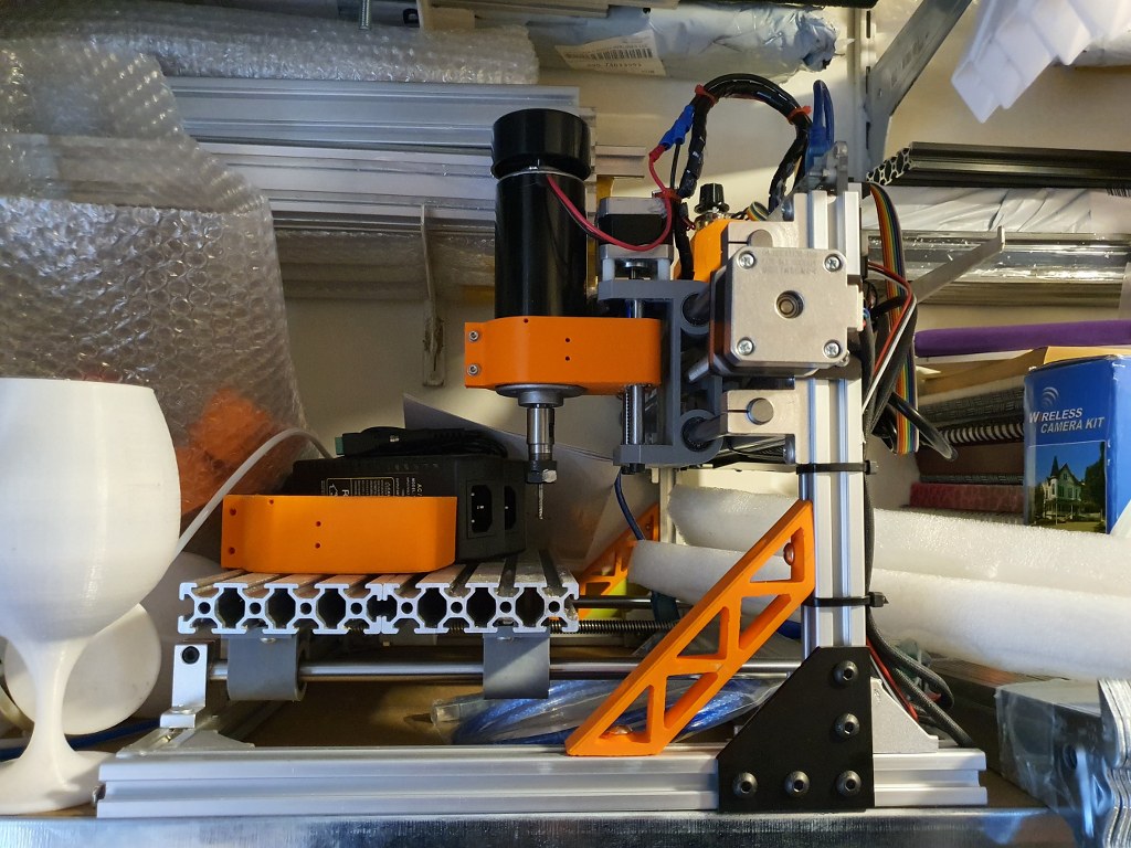
After making the base frame and the Y axes, the rest is more simple. Just get the 2040 pieces in place, I started with only the lower one. The put all in like the rails, the ball bearin screw bearings, the ball bearing screw, coupler between screw an motor, the stepper motor and the X axis is done.After the X axis, the Z axis is placed in. First put the rear plate on the 4 linear rail sliders and mount the ball crew block of the X axis to the rear. Then, put the vertical short MGN12 rails on the rear Z plate. Then put the bearing for the leadscrew on the top plate’s undernetah. Put the corner pieces on the top plate and mount it on top of the rear Z plate. Then, feed the threaded rod through the top bearing, mount the angine an d teethed wheels and feed the screw through the nut… Are you still with me?Top view to get it more visble: engine and leadscrew connected with teethed beltI decided to put 3 connecting pieces between the frame’s left and right Y axes to maintain stability and rigidity. After I put these in, the frame was very square and stabele, but also heavier..)
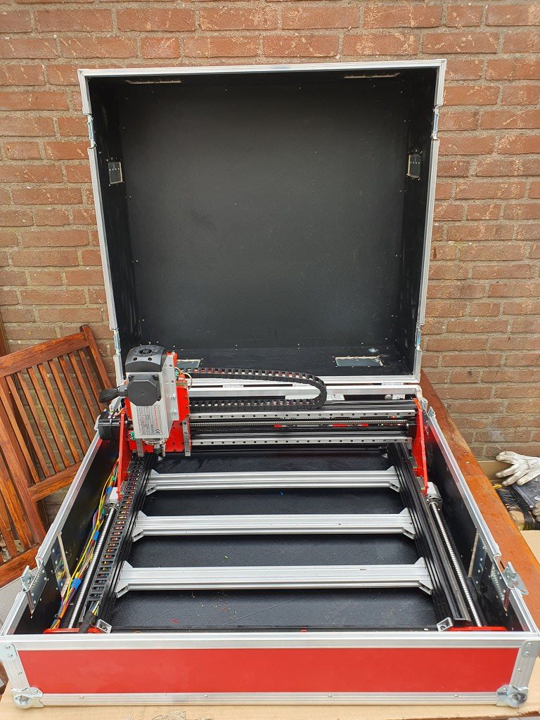
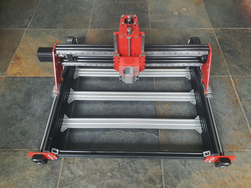
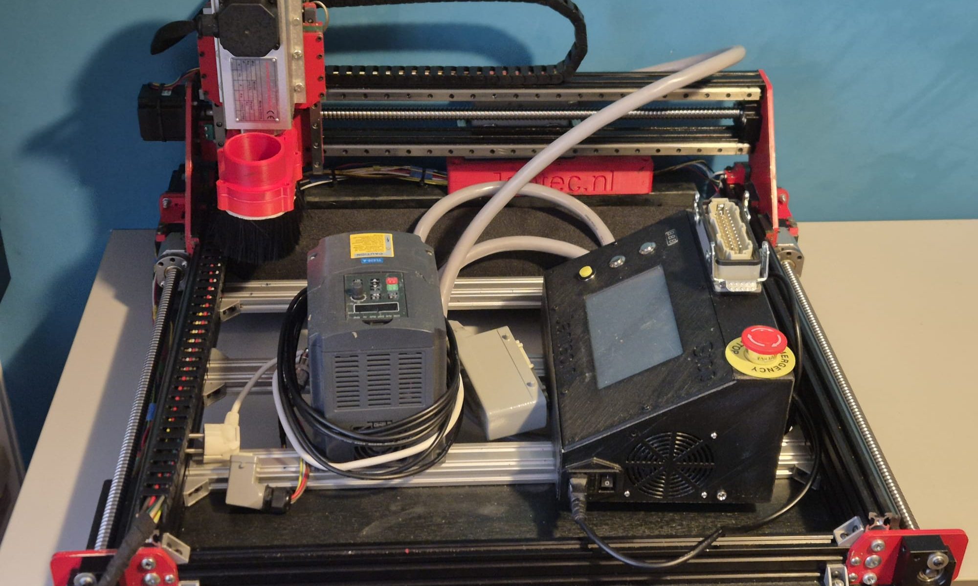
Last time that you see the frame without any wire. Next I will get the endswitches on the farme, the spindle and all other parts that are required to get my Indymill up and running! BTW I mounted 4 heavy purpose rubber feet under the frame, just to prevent having any tordoial stress to the frame when I put the frame anywhere to be used.
And- I must say, this build goes quite well. The materials are OK, and the guideline from the build description was very good. Although I never use it anymore. The build is quite self-explanatory once you start building the Indymill CNC machine. I also cahnged quite some parts, and made alterations where I felt this would improve the machine to fit my purpose better.
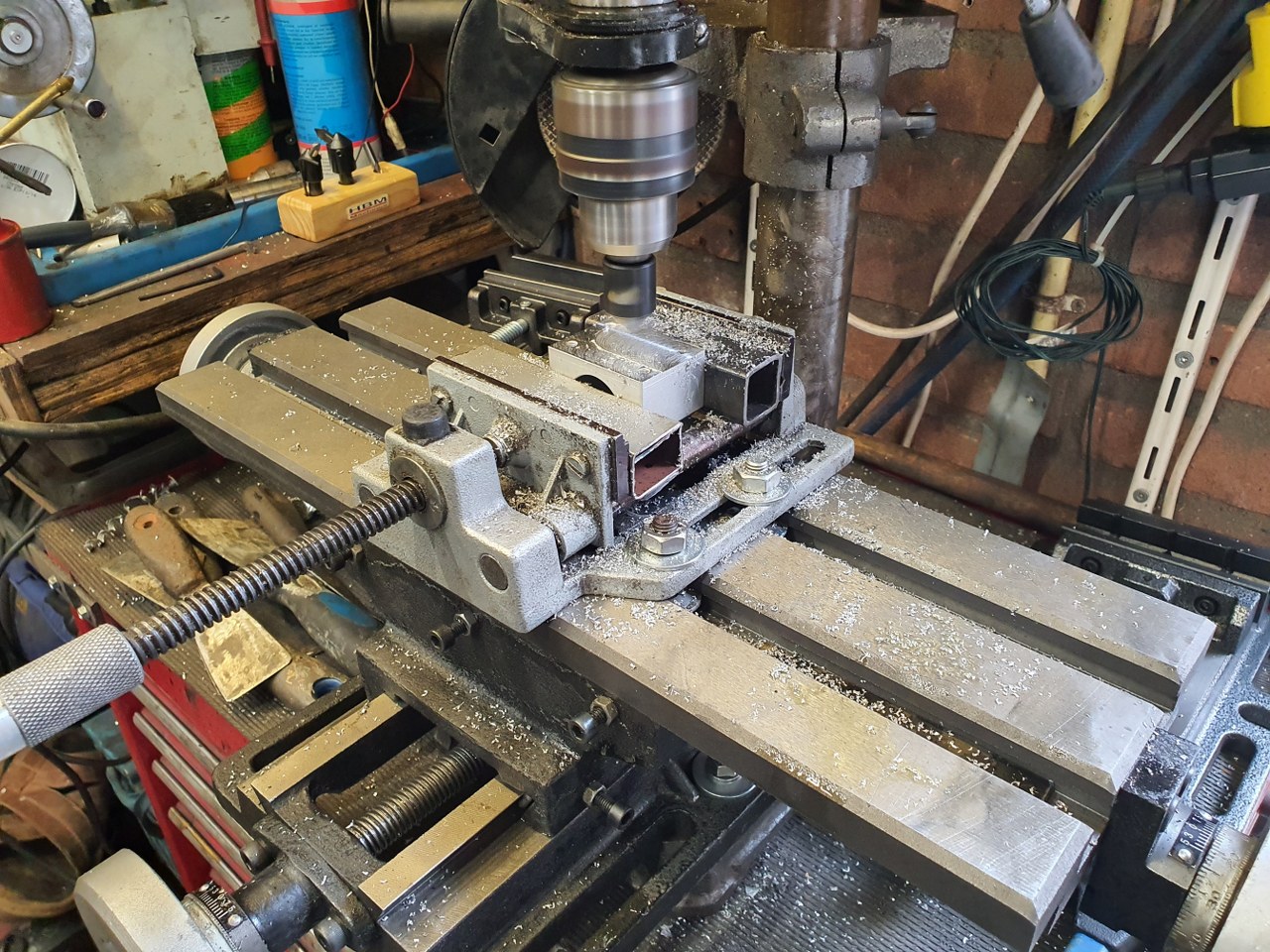
My very basic mill is just an old drill machine with a large X-Y cross table mounted underneath. But- for basic milling it works.
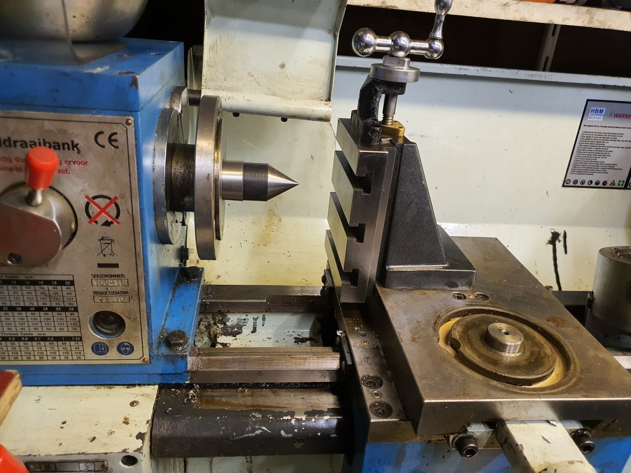
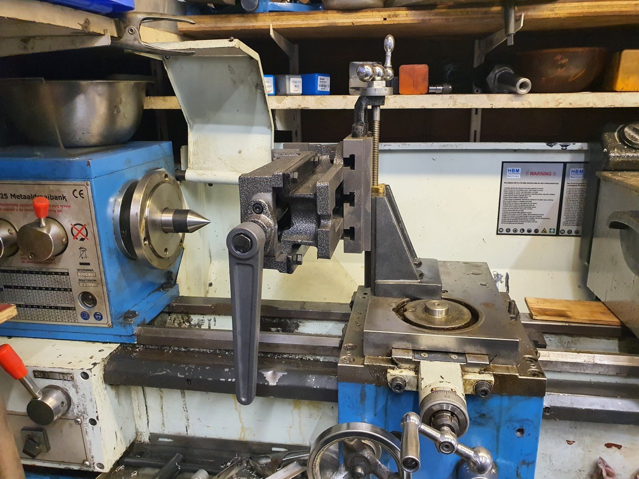
In the process of change: My HBM25 lathe is going to be changed (temporarily) to act as mill. I need some parts milled flat and square, this will do that. Waiting for the MK4 sleeve for my MK3 milling head…All mounted to the lathe
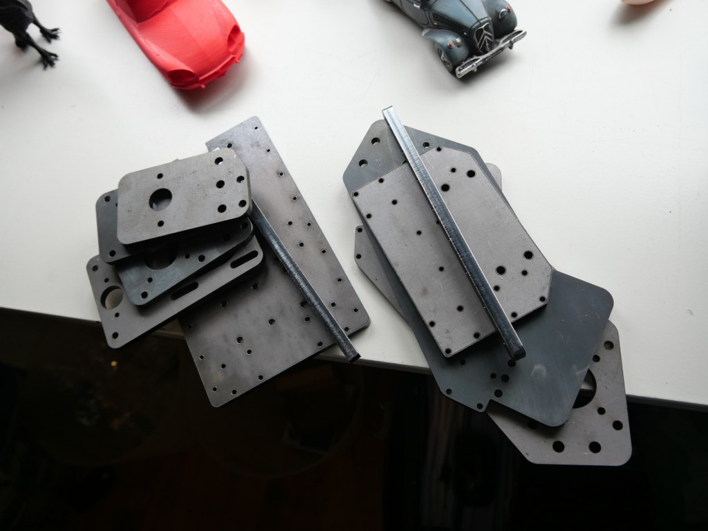
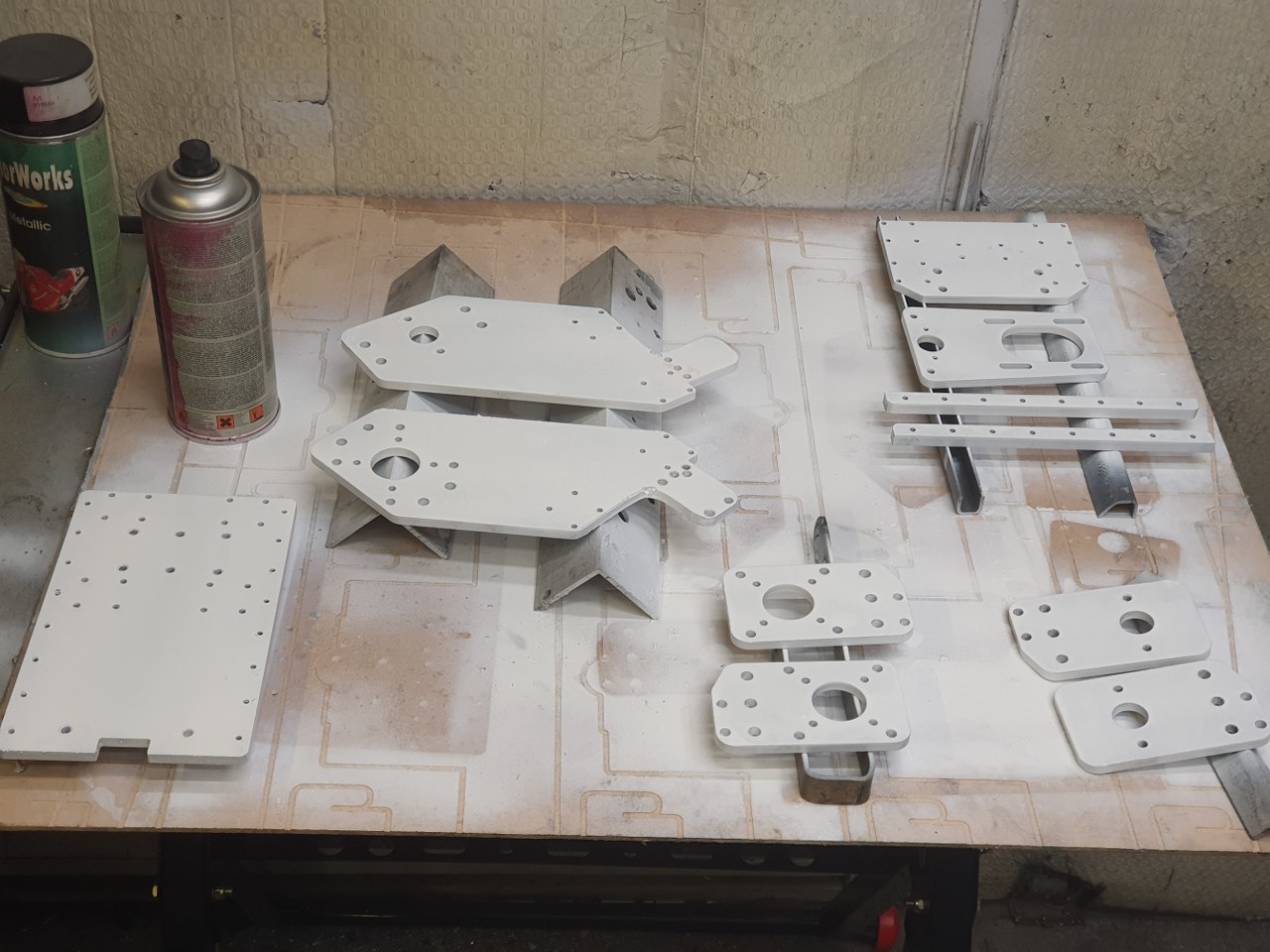
The required iron plates were not available in ready- to use state at the time I needed this, fortunately I could buy the plates as a kit with all of the drilled holes already in it, non-painted. And- all of the thread tapping still needed to be done. Since I am also making changes to the design of the millling machine, some holes will be altered and this is best done when the plates are not yet painted.
The raw streel for the Indymill. I put small colored circles where the thread needs to be tapped.
Rustpreventing primer spray-painted the Indymill’s iron plates
2021 05 13: Yesterday I received the iron plates for my Indymill from Nikodem Bartnik, and it was all very well packed and quickly delivered!
As I always do on any build, I first check the separated axis for best fit and possible improvements. I started with the Y-axis. In the below picture, the left side of the macine is shown, being the left Y-axis. The rest of the machine is not yet attached.
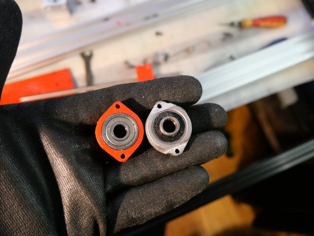
This is how I started with the original design. Ball bearing block (orange) and screw mount (red) are both 3dprinted here.
The Y-axis is somewhat limited in its drive towards the rear of the Indymill CNC machine, due to the bridge plate for the X-axis. This bridge plate is blocked in its movement towards the rear because it hits the bearing block (orange part) that holds the ballscrew in place. By removing a small and unused part of the bridge plate, the movement can get about 6 cm extended towards the rear. The pictures are attached to this post, please see how I made this.
Maximum movement towards the rear (top in the picture) due to a removed piece of the bridge plate
I used the plasma cutter to cut the parts out of the 6mm steel plates and after this was done, I used the lamel grinder to make it smooth. Although I used a guiding rail for cutting, the power was apparantly a bit too much so it is not a very beautiful cut… -) No worries because all still fits very well.
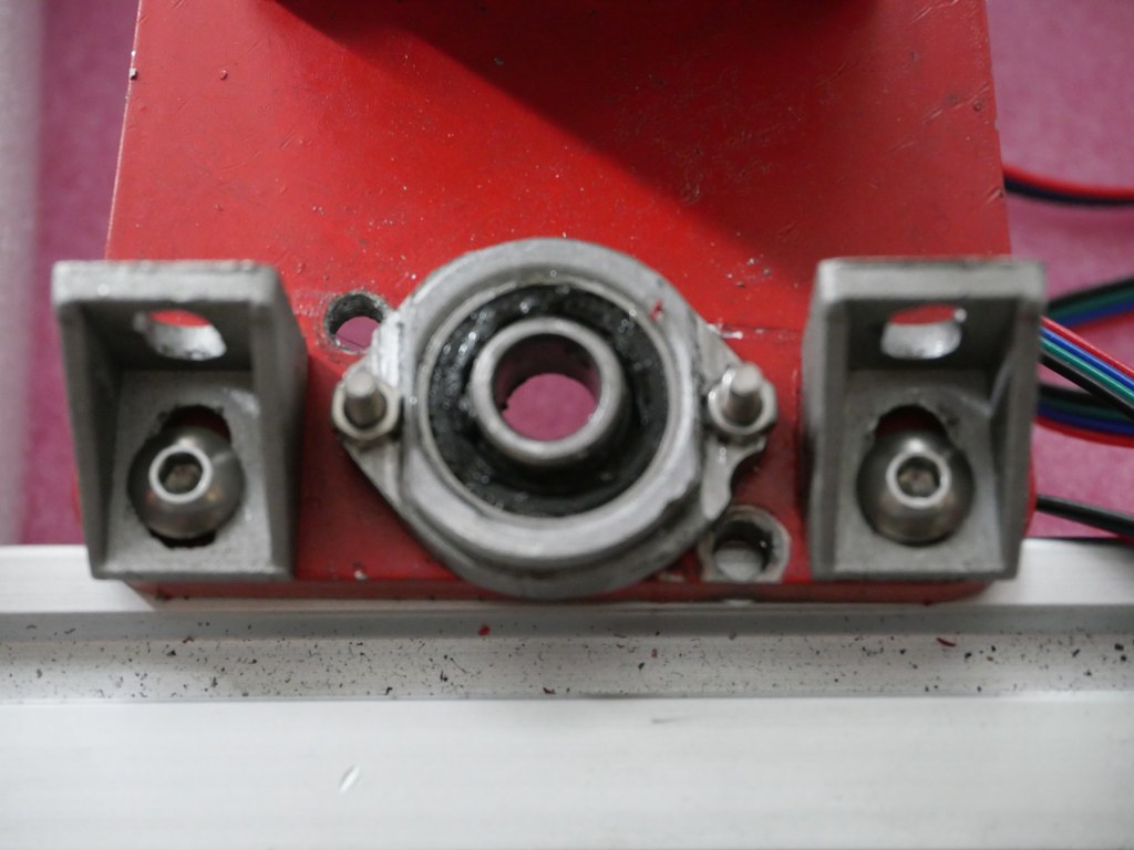
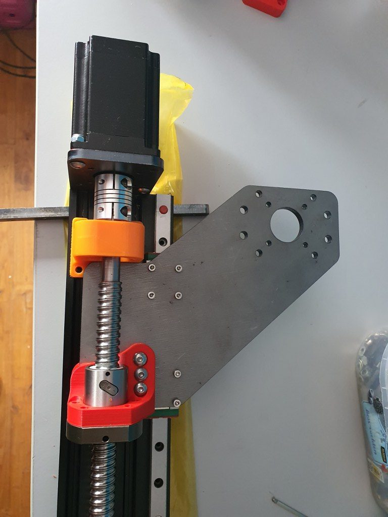
BK12 original axial bearing (black) for 1605 ballscrew and -nut (red) with Nema23 holder (orange) with an attachment for the original BK12 bearing, both placed on the left Y- axis of the IndyMill CNCAn original nut holder for a 1605 ball screw nut, machined down on my manual mill to fit the Indymill’s Y-axesThe nut holder in place on the left Y axis
Since Corona was still around (May, 2021) , I had some time available to spend on other things than just work.
I already had an upgraded 3018 CNC-machine with a 0.5 kW spindle motor,
and a simple GRBL 3- axis board that works very well. But- it would be nice to make a CNC machine that can really work with aluminium and possibly also with copper and brass. I have already done some research in the past about what sort of CNC machine would be right for my goals. And the IndyMill CNC macine was already on my mind for over half a year. So-last week I ordered the manual and the steel plates
for the build and ordered some other parts from Ali. I also have quite a lot of parts on stock, from my 3d printer supplies. The Nema23- motors and the extrusion, motherboard, drivers, power supply, switches and probes are already available.
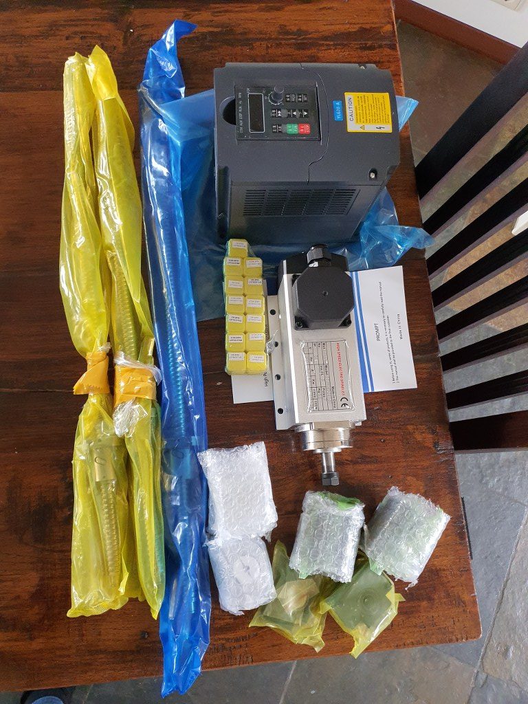
2021-5-09; First parts delivery for the Indymill: 3 ball bearing leadscrews with kit of end bearings and screw block holders, the frequency regulator 1 phase in, 3 phase out and the 1.5 KW 3 phase spindle of 3.6 kilograms
The required printed parts are being printed right now (early May-2021). I am printing all the upgraded STL’s, latest version as these are freely available on Thingiverse (just search for IndyMill) . And then you see the power of sharing: the design was already great, and with the upgrades it got even better. The upgraded versions of the mounts for the linear bearings are really a lot sturdier than the original design and the new endstop holders are very handy to have.
I roughly calculated the costs for building this machine and it was a lot cheaper than buying a similar CNC machine of this size. If you purchase wisely, the costs for all materials can be just under Euro 1000, if you follow the original BOM and including the 1.5 KW air-cooled spindle motor with regulator…
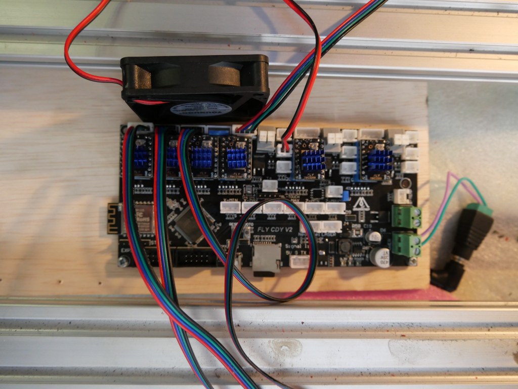
If you want to install another board than the standard Arduino UNO with the standard Arduino CNC shield, this can set you back an additional amount of 120 to 500 Euro’s. I use a FLY_CDY_V2 with Mellow’s original TMC2209 stepper drivers. DO NOT FORGET to set the switches on the underside of these steppers to ON if you want to use sensorless homing!
My add-ons to the original build:
Currently I use a 10 Amps detachable 24V PSU, will become a 30 Amps one.
Sesorless homing with the use of a FLY-CDY-V2 motherboard and TMC2209 stepper drivers. This works awesome but I moved on to add endstops and make a more stable and exchangeable setup.
Original mounts and usage of the ball bearing screw nut’s holder, and of the BK12 nd BF12 original bearing holders to keep the ball bearing screw from moving the wrong way.
Altered Z axis setup with a better nut holder, and a better top bearing
.
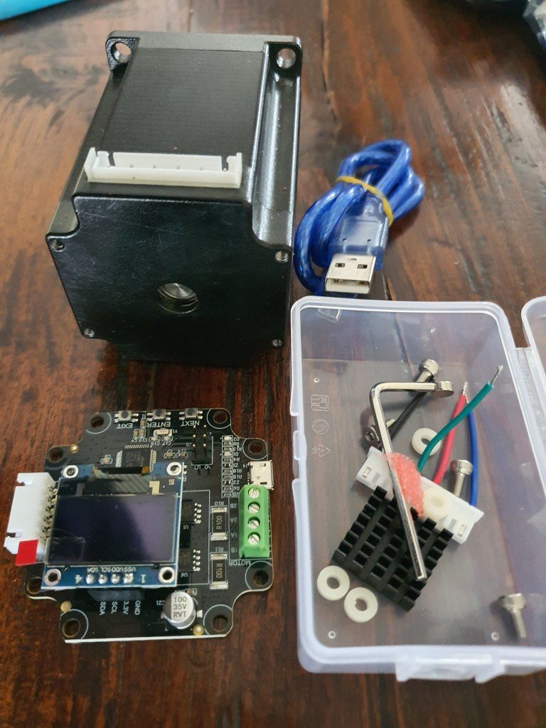
Closed loop NEMA23 stepper motors drivers MKS Servo57A V1.0 will be fitted to the rear of the steppers, still to be mounted but will conflict with sensorless homing
Nema 23 stepper with the Closed loop kit
10 mm GT2 200mm belt between the Z motor and the Z-leadscrew with GT2 10mm wide 16-teethed wheels
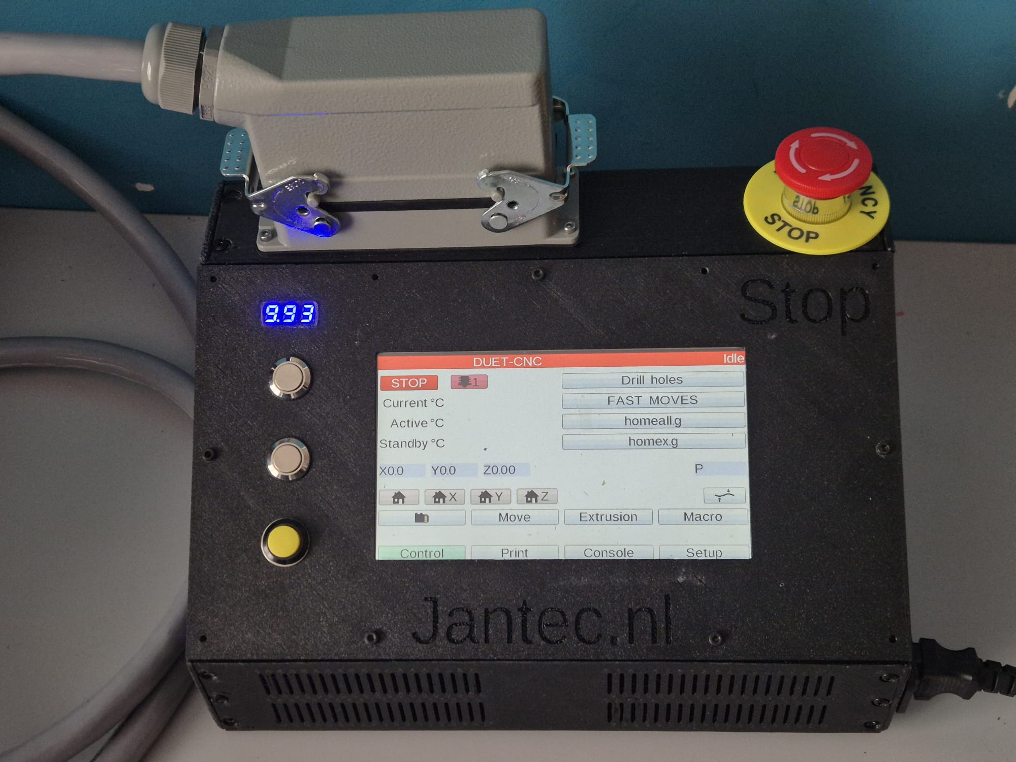
On the Duet support website a project is available to convert such a device to a serial interface, with a programmed Arduino (pro) mircro or -nano built-in the device:
Solid connection plate between the rear side of the upper and lower linear rails of the X-axis. Still to come.
Piezo-probes on all axes’s start- en end positions, instead I first setup the FLY CDY V2 reprap board with TMC2209 and sensorless homing, and later with mechanical endstops.
Coolant mist installation and fluid gathering-, pump, reservoir et cetera is ordered. Stll to be installed, and the pumps were not supplying sufficient pressure for the flood mist, have to look for another solution.
Independantly driven (and independantly finetuned homing) Y-motors to prevent any possible problems between left and right. This works flawless with the FLY_CDU_V2 reprap setup but it took me quite some hours of finetuning to work with the 3.5 kilogram heavy spindle motor…
2080 profiles all around (also front and rear) with 4 extra-wide corner brackets underneath. I chose to implement this differently with 3 additional bottom connections and corner brackets, since I need the front of the frame to be low and give way to the spindle vacuum hose.
Amd – the frame as it is ready, but with the spindle holder of the 500 Watt motor. I will not use this motor after all for this build–
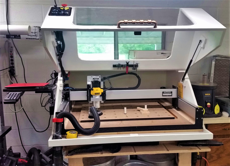
Smart enclosure with Scheppach vacuum cleaner connection like this example from https://www.shophacks.com/cncenclosure.html#/ THIS IS REALLY NEEDED!
My solution for an enclosure ia a 84x78x45 cm flightcase
Protecting guards for all leadscrews and linear rails (ordered in China)
Later if possible: Wheels on the rear or on 1 side and a handle on the front (or other side) to stow and store the machine easier
Easily detachable control unit(s) with solid connectors
I started with a FLY_CDY-V2 reprap board to experiment with reprap CNC and the webinterface that has been developed for this setup.
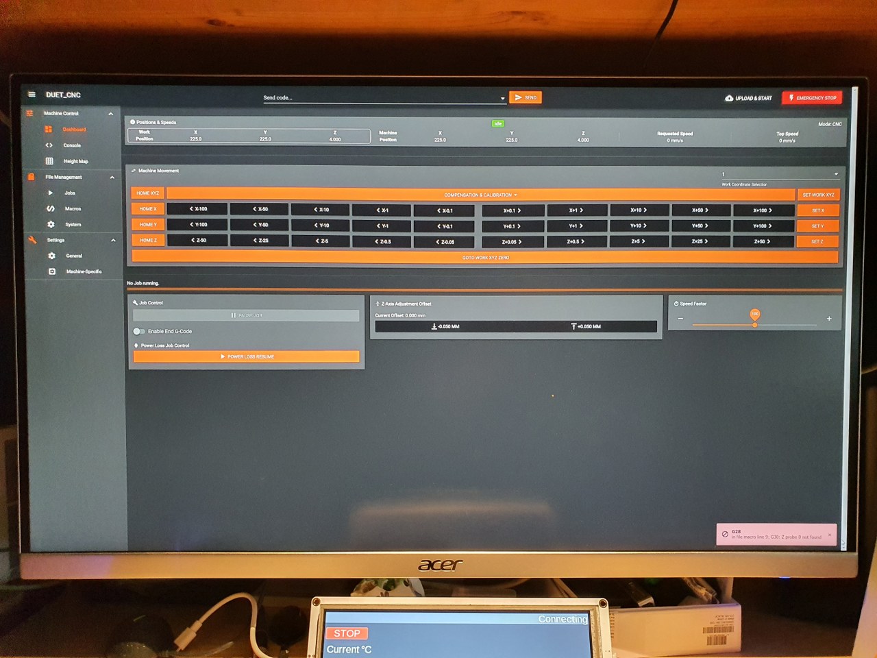
This is achieved with smart dual homing of the dual Y axes, and gives me a lot more control on the machine. It is also already possible to just send GRBL-based Gcode to the USB port of the machine and use the reprap FLY board simply as gcode-interpreter to steer the machine. But for now I use the webinterface to upload and run any gcode.nc CNC file, which works perfect!
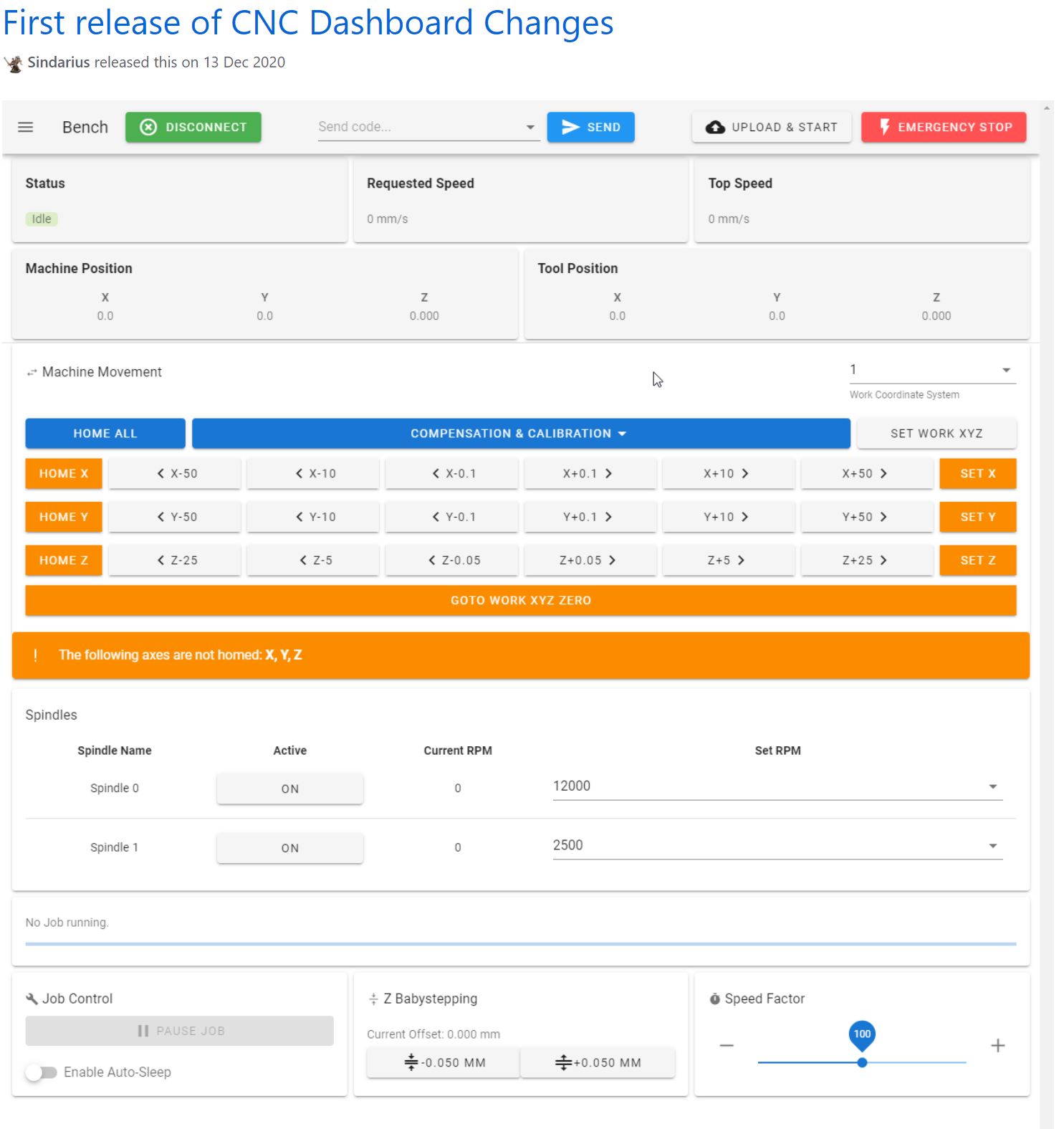
Picture of the CNC-adapted and already available webinterface for reprap, especially tailored for CNC (by Sindarius, work ongoing):


 and a simple GRBL 3- axis board that works very well. But- it would be nice to make a CNC machine that can really work with aluminium and possibly also with copper and brass. I have already done some research in the past about what sort of CNC machine would be right for my goals. And the IndyMill CNC macine was already on my mind for over half a year. So-last week I ordered the manual and the steel plates