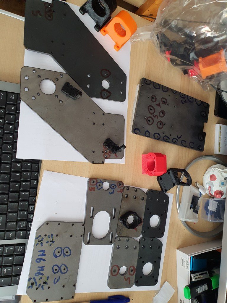
2021 05 13: Yesterday I received the iron plates for my Indymill from Nikodem Bartnik, and it was all very well packed and quickly delivered!
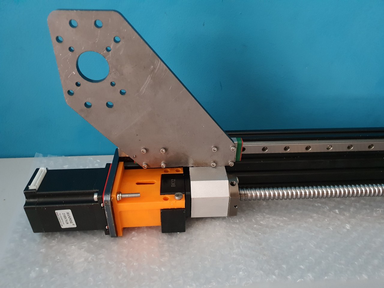
As I always do on any build, I first check the separated axis for best fit and possible improvements. I started with the Y-axis. In the below picture, the left side of the macine is shown, being the left Y-axis. The rest of the machine is not yet attached.
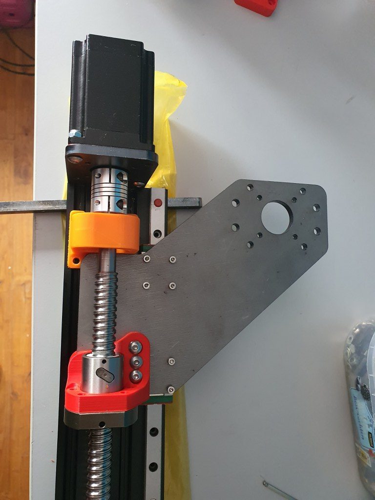
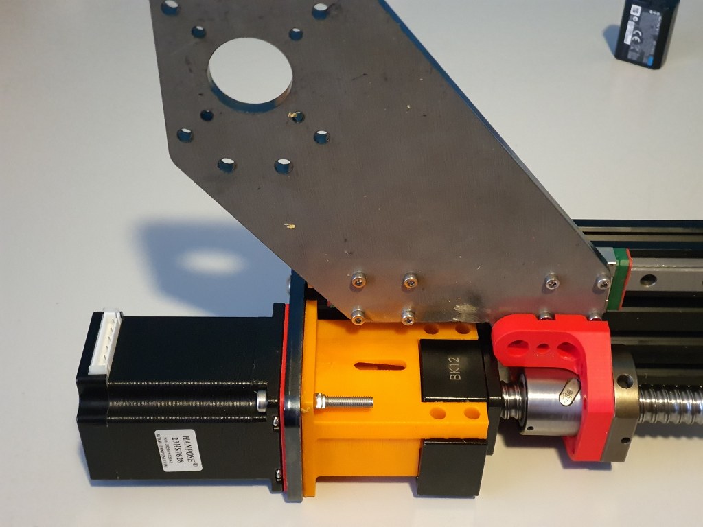
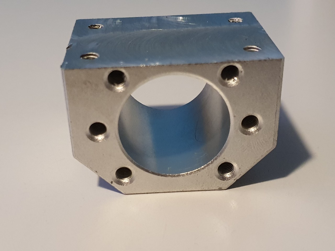
The Y-axis is somewhat limited in its drive towards the rear of the Indymill CNC machine, due to the bridge plate for the X-axis. This bridge plate is blocked in its movement towards the rear because it hits the bearing block (orange part) that holds the ballscrew in place. By removing a small and unused part of the bridge plate, the movement can get about 6 cm extended towards the rear. The pictures are attached to this post, please see how I made this.
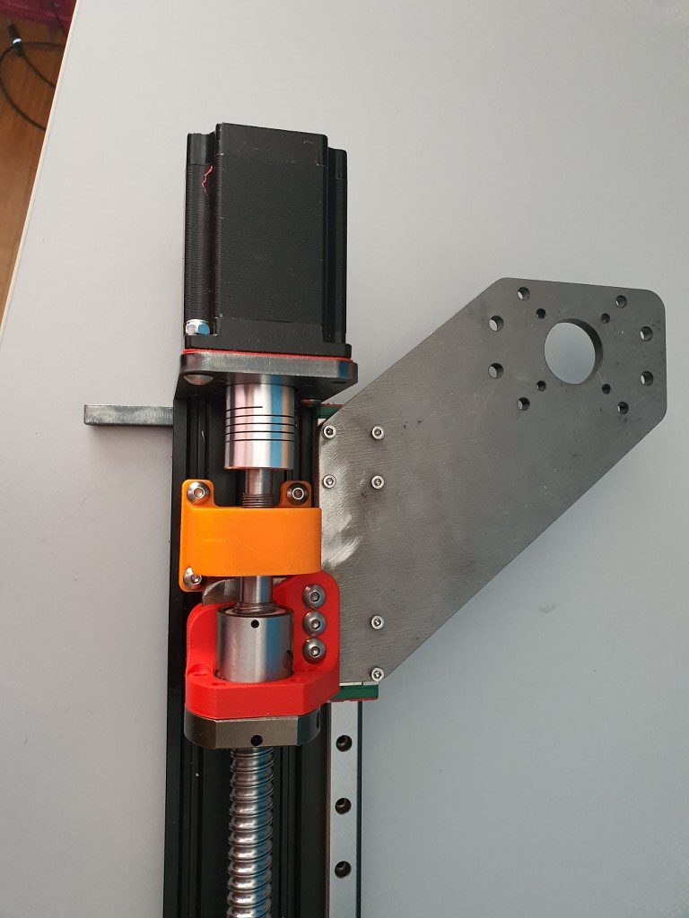
I used the plasma cutter to cut the parts out of the 6mm steel plates and after this was done, I used the lamel grinder to make it smooth. Although I used a guiding rail for cutting, the power was apparantly a bit too much so it is not a very beautiful cut… -) No worries because all still fits very well.