Is E3D tool changer Z-homing with Voron TAP possible?

HOW DOES IT WORK WITH THE E3D TOOLCHANGER?

The system whereby the E3D tool changer determines the Z value of the four tools is fixed in the preset system files. This means that you perform a Z homing paper test for each tool to determine the deviation of each tool relative to T0, which is the leftmost tool. You enter the result in the config file as the Z-value for each tool, whereby I usually use “0” for T0 and the general Z-probe value, which I determine as the difference between the manual probe on the carriage and the nozzle height of T0.

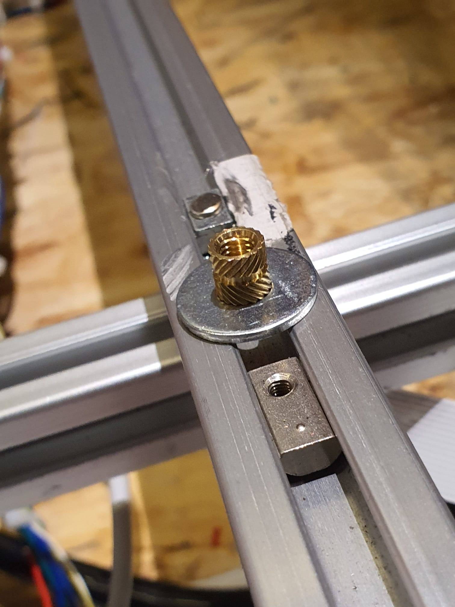
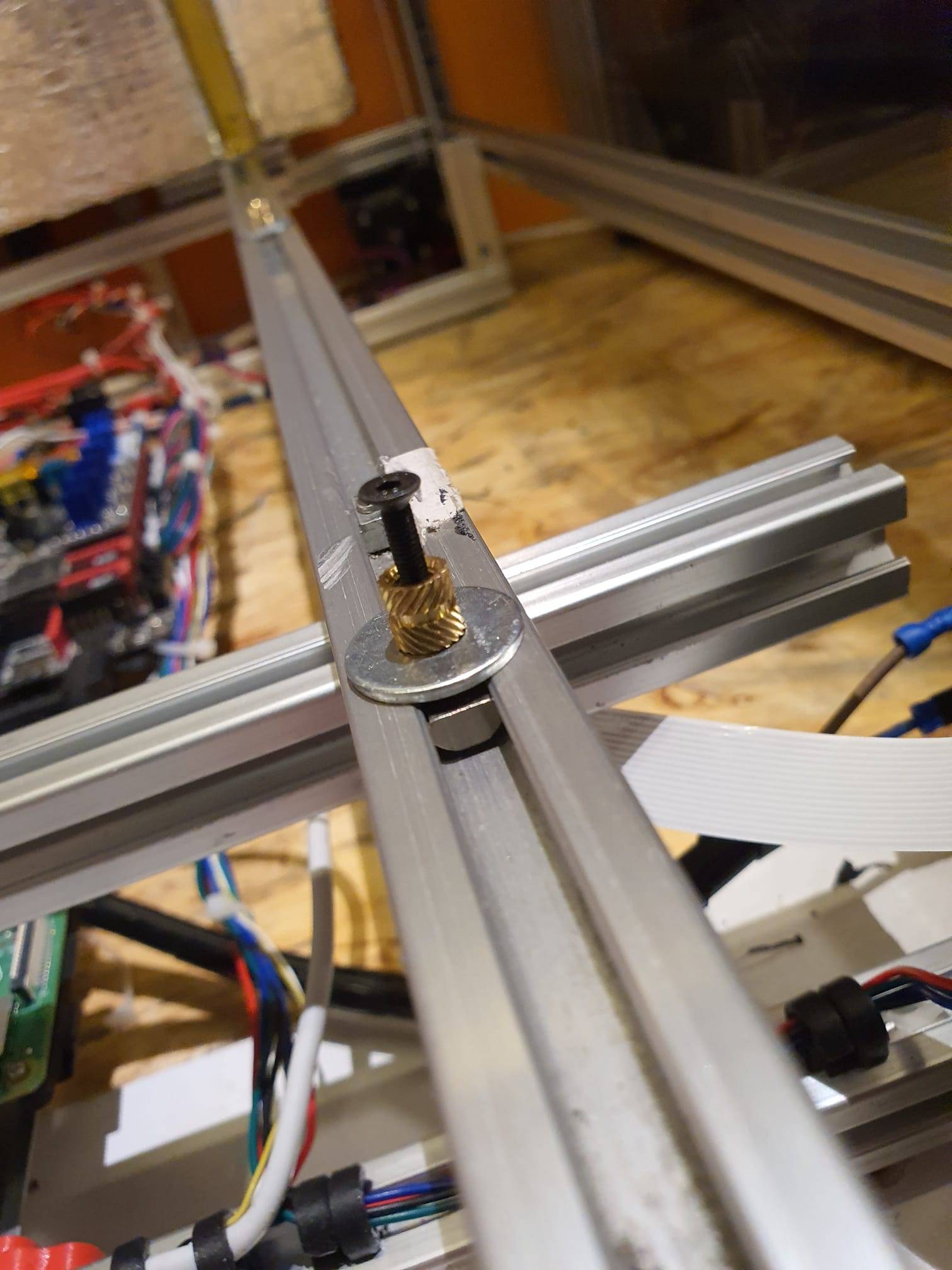
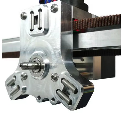
First, you need to determine the Z deviation of T0 relative to the Z value of the carriage that picks up the tools. This is done by homing the bare carriage with a Z probe switch under the carriage to Z value = 0 on the bed.

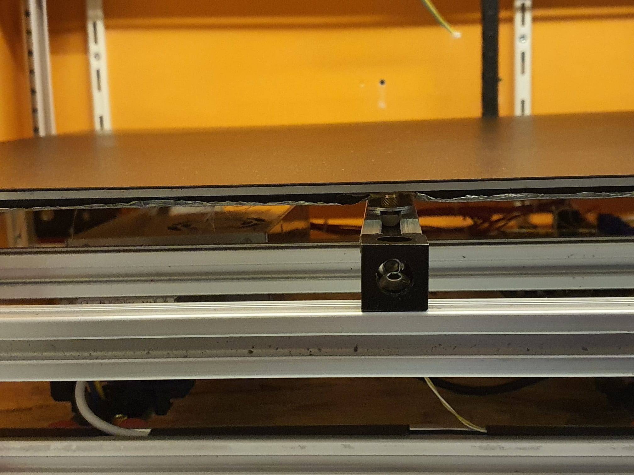
Then you do a tool pickup from T0 and measure the height of T0 as the Z value. You then enter that value as the probe value in your config file. I find all this rather cumbersome, especially because everything changes when you change a nozzle, for example.

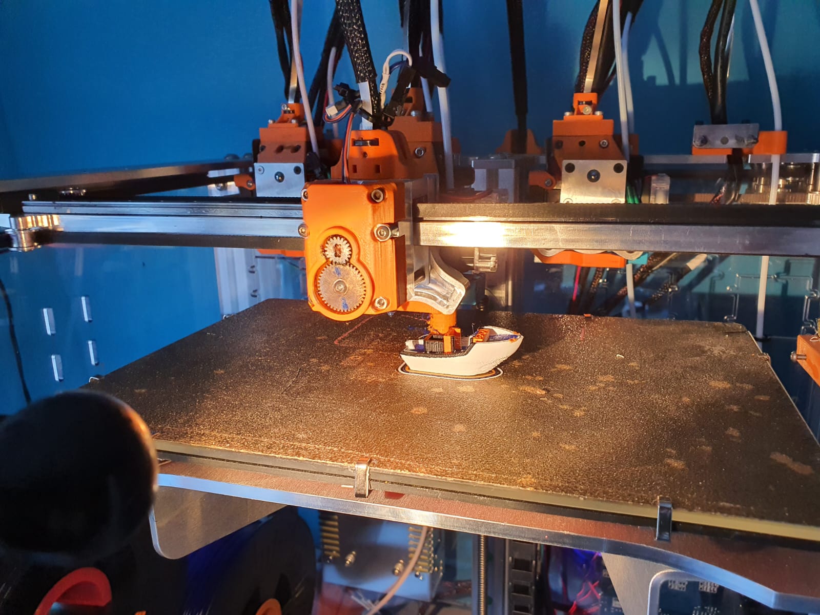
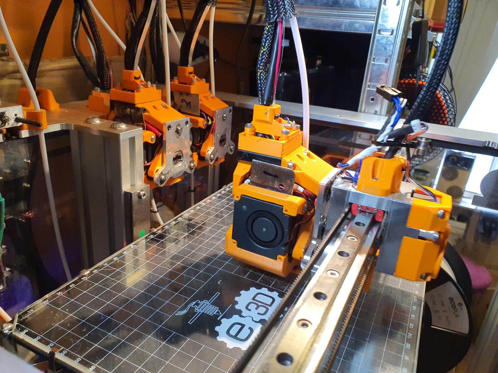
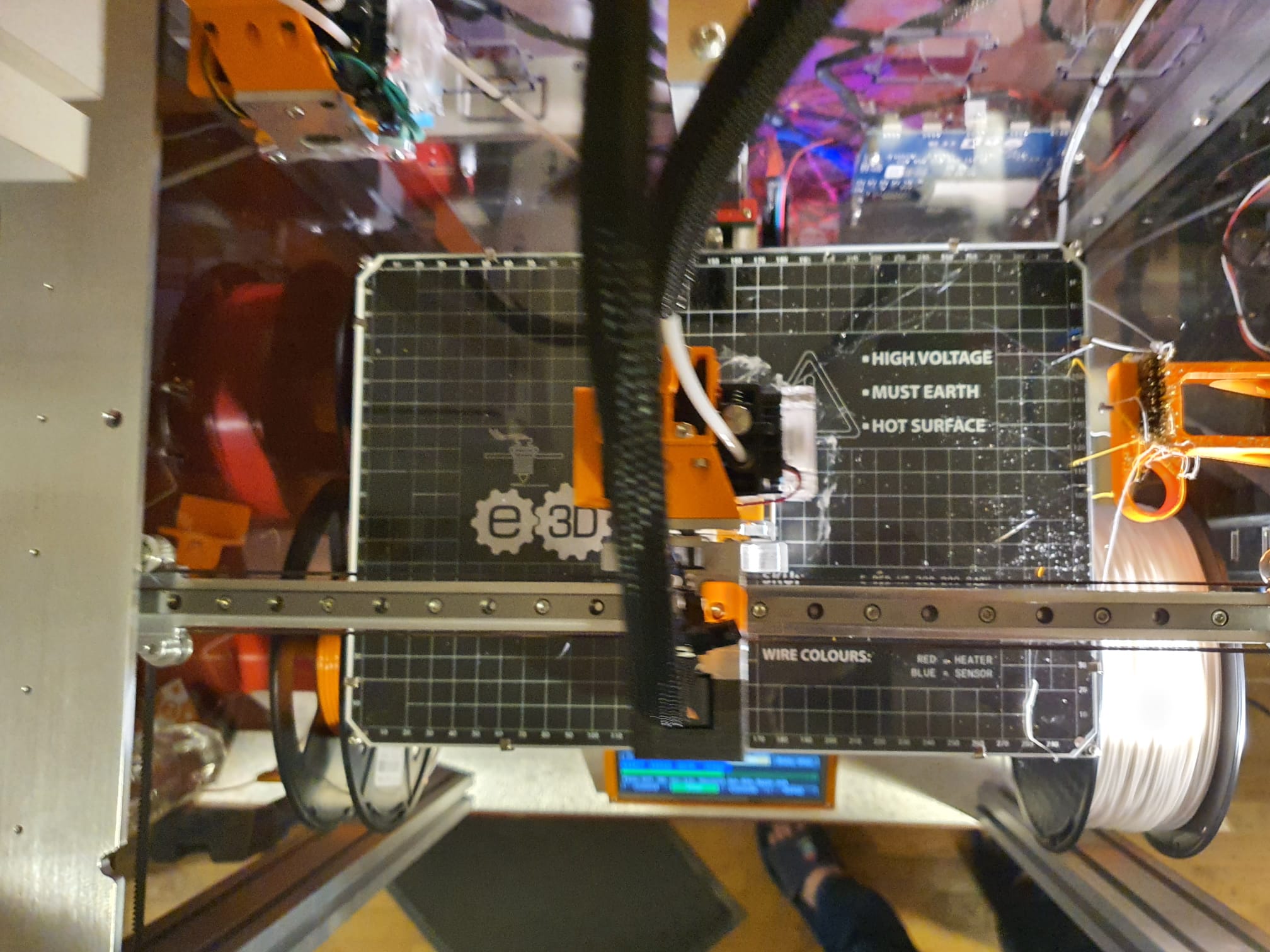
Below video: E3D toolchanger homing the carriage and do the tool pickup

DESIRED SITUATION

Ideally, I would prefer to have each of the four tools, i.e. T0 to T3, home X, Y and Z every time a new object gets printed, and in this manner you can also just select any tool to do the bed mesh.

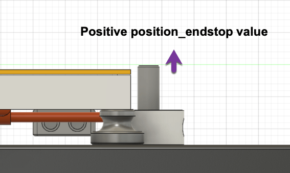
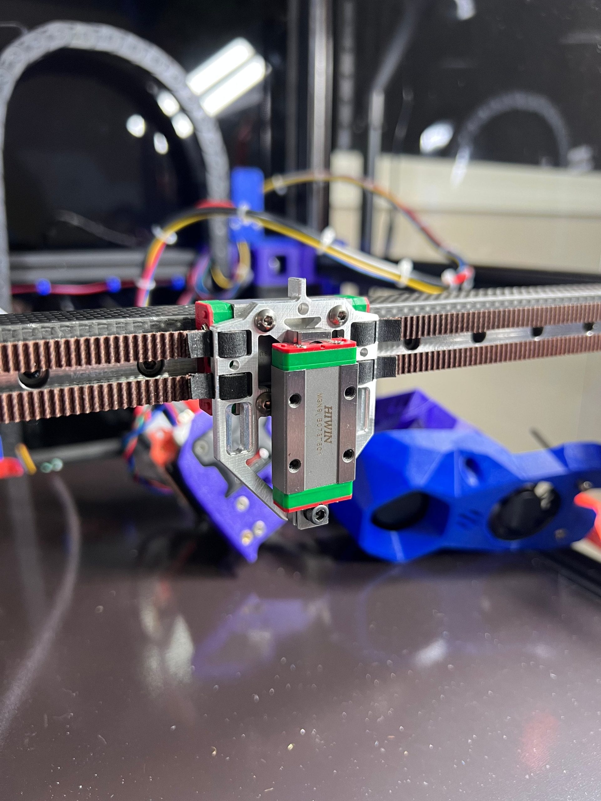
You then take those four Z values as the Z=0 value per tool, and you’re done. This works great with the Voron that I run with TAP Z-homing! It doesn’t matter what you do with your bed or your hot end, gantry, etc. It doesn’t matter because the nozzle is used as a mechanical Z-homing tip.


The tool pickup (the trolley) is very securely attached to the X-axis. The best solution would be to allow this entire unit to move vertically in order to enable the TAP function. That is still a challenge, partly because the A and B belts are attached to this trolley. This only seems possible with a new trolley to which the belts are attached and a separate tool changer pickup next to or in front of it. I then still need to create the TAP function between the two parts. And if the tool changer is placed in front, the X-axis must be moved back on the Y-axes. I’m not sure how that will fit….

After exploring all kinds of possibilities, this one remained: Keep the tool pickup in the same place and work with existing resources. Saw the mounting block on the X-axis slider into 3 parts and then mill 1 mm off the centre piece on both mounting sides. Adjust the side plates to which the belts are attached so that these plates can be reattached to the middle section of the slider block with new countersunk screws. The through bushings on the bottom no longer pass through the plate, and the plate must be milled away at the corners, just like on the top, to create approximately 5 mm of vertical play. Mount the two lower connection points of both side parts with two 1 mm spacer rings each so that the carriage can move up and down and the sides remain at the original distance from each other in order to maintain the stability of the moving construction. An additional mounting block for the vertical linear rail of the TAP slider is placed on the centre mounting block of the X-axis slider. Extension pieces are attached to the front and/or rear of the tool pickup, to which the TAP slider with the moving part is attached so that everything can move up and down by approx. 3-4 mm..

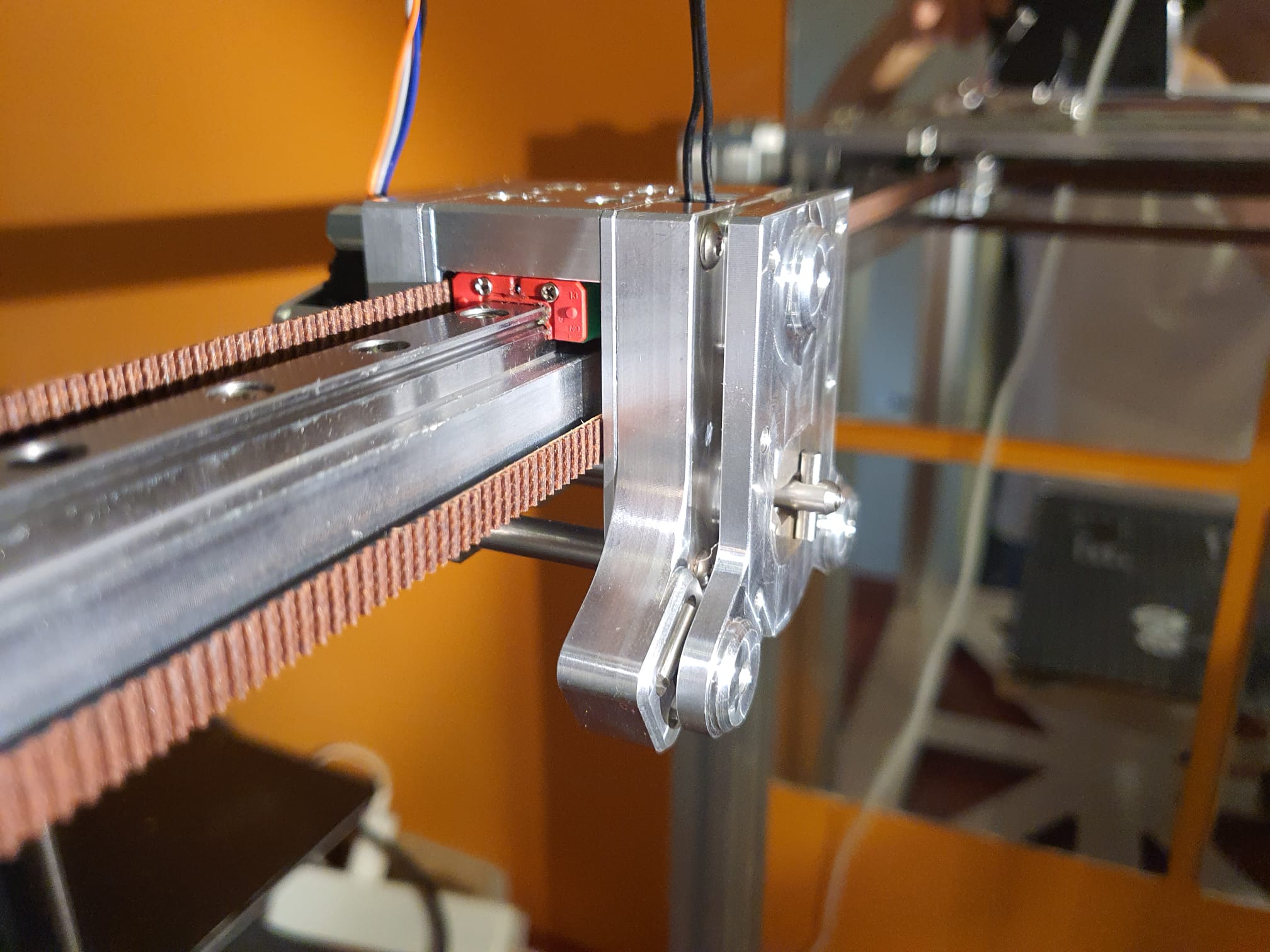
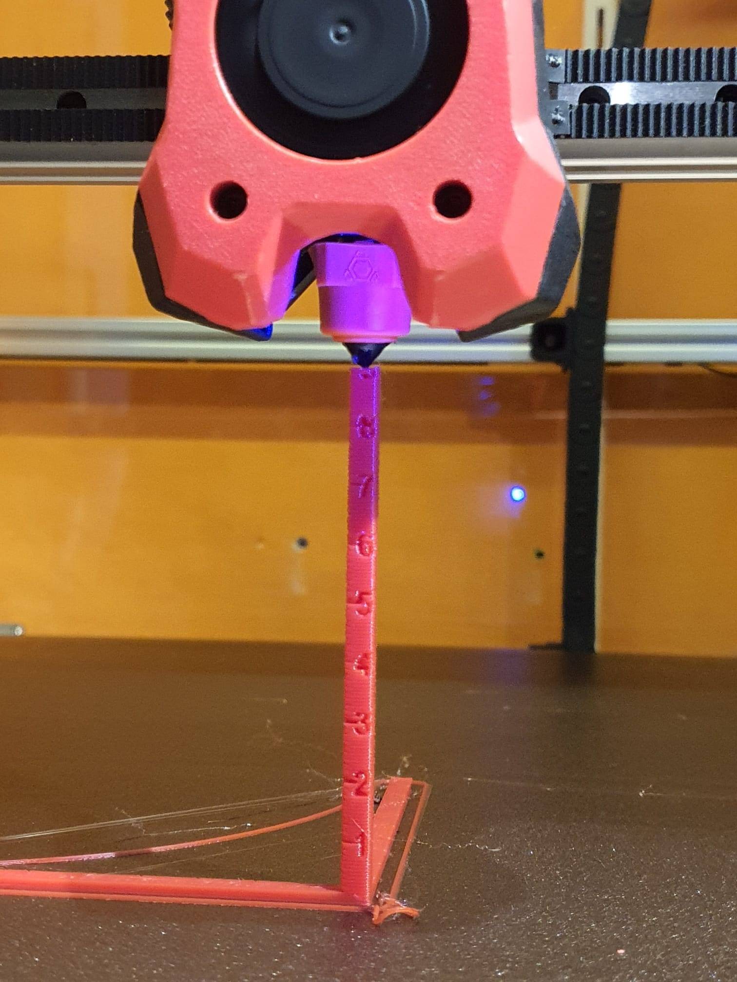
How the TAP function works on a Voron2.4 3D printer

ADDITIONAL: Self-searching tool changer

And while I’m at it: why not make a self-searching tool changer? Roughly set it up with the XYZ coordinates per tool, the last part electronically with a guide system between the pick-up trolley and the tool, and the final fitting with the existing mechanical fitting.

Instead of determining exactly where each tool should be picked up and put away by trial and error, you could use an electronic guidance system to aim precisely at the right tool when it needs to be changed. No more hassle with X-Y settings and homing axes. Because if anything changes as a result of mechanical stress in the frame or due to small deviations from the X and Y homing, picking up and putting away tools will regularly go wrong.

One possible way to do this could be a passage LED/LASER system, such as those used at shop entrances.

.


mini focussable laser module


mini laser receiver module


Or simply use infrared, which is invisible but also much less dangerous.


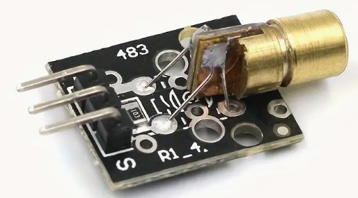
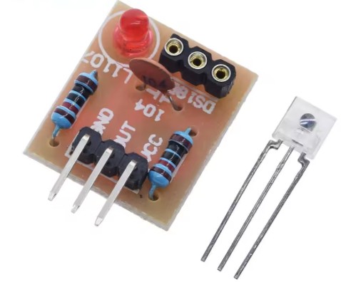
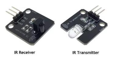
To do this, you use a targeting laser, such as in a levelling system, or an infrared laser with a receiver.

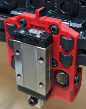
This is placed on top of the X-axis on the moving toolhead and is aimed at the tools, at a 90-degree angle to the X-axis.

You then activate the correct tool you want to move to or pick up as the receiver.

With an X-sweep movement, you can make contact with the receiving tool and then move in a straight line towards the tool until you reach the pick-up point, which is specified in absolute Y value in the configuration file. Sounds like a great development!

ADDITIONAL: Precise XYZ homing of the tools

And I would like to have a way to centre X, Y and Z of each tool nozzle in detail relative to the other tool nozzles, just like with my CNC machines:

3D Print Head Alignment Block

With such a head alignment block, you can accurately determine the position of all axes on a CNC machine. First, you need to determine the approximate position of this block, with an accuracy of approximately 1 mm on the X and Y axes.

The alignment block is electrically insulated and works by making contact between the tool tip and the block.

How does homing with an alignment block work?
You programme a centring macro in G-code.
First, you temporarily set the motor power to the lowest possible value to avoid damage if anything is in the way of the moves to be made.
Just as when I regularly do a home-all, with this new method you also set the bed and the relevant tool nozzle to operating mode (e.g. bed at 70 degrees and nozzle at 180 degrees).
Then you do a normal XY homing, which in my case works with limit switches (or optical switches) at the start of the X and Y axes.
A Z-homing action is also necessary unless you do not want to remove the Z-move block that occurs when you have not first homed Z.
Then move the Z-axis up sufficiently to avoid hitting the block.
Next, move to the absolute XY position of the block.
When you are above the block with your tool, home your Z.
Then home on Z+0.3 both -X and +X, and in the middle of -X and +X home -Y and +Y.
The result is the exact position of the centre on the flat Z plane of the alignment block.

Because you know exactly what the position is in relation to the bed centre and from X0, Y0 and Z0, you can translate this directly into the macro and enter the Z0, X0 and Y0 values as absolute values.

It should be possible to home the E3D tool changer tools in this way as well, with Z using the TAP function and X and Y using electrical detection as described above for the CNC milling machines. We will see if and how this will work as a supplement to TAP-Z homing with the current X and Y microswitch homing on the X and Y axes.


CONCLUSION -FOR NOW-

The credo still seems to be: If the E3D tool changer is working, it’s best to leave it alone. That doesn’t suit me at all, because I often move my printers around. And that doesn’t always go well.

So I’m going to look into these issues and, if possible, build something!

Replacing the heater mosfet B6066 of a Mellow Fly SB2040 pro plus Canbus 3d printer’s Voron Stealthburner toolhead PCB

Due to my careless behaviour I damaged the hotend’s heater Mosfet of my Voron 2.4’s Stealthburner toolhead’s PCB.

This toolhead PCB is a Mellow Fly SB2040 Pro plus. It has an accelerometer, a 2240 TMC, and it works with PT100 for the heater. It  works very well through Canbus and my installed PICAN USB-interface on the RPI.

But- when I was installing another nozzle in the hotend, I shorted the ceramic heater cartidge and blew the heater Mosfet. See the next picture:

I ordered a new toolhead board and now I could tell the part number:

I ended up ordering 5 pieces of replacement B6066 Mosfet modules on Ali, and they were delivered yesterday, within 2 weeks.

I desoldered the defective one with my SMD heatgun, and ut a new one in with that same heatgun, works very well!!

Switched to a Chinese high-flow CHT nozzle – Now, what is wrong with this ABS printed test cube?

So- what do you think is wrong with this ABS printed testcube after my switch from a standard 0.5 mm nozzle to an 0.6mm Chinese CHT high-flow nozzle?

I did not change anything other than the Curaslicer settings from 0.5mm to 0.6mm and also in Klipper, in the printer.cfg I also changed the setting from 0.5 to 0.6mm nozzle diameter.

Obviously, I also resliced the gcode before printing the testcubes.

It has been printed on my Voron 2.4R1- 300. with a nozzle as shown in the below picture:

These specific nozzles should be able to produce more flow since the input channel consists out of 3- instead of 1- little hole.  The tip is – of course- only 1 hole.

Remedies:

After the failed print, I did the following:

Changed the ABS filament for a fresh pack. No change.

I checked the retraction settings in Curaslicer which were just fine, between 0.5 and 1mm.

Tested the gcode on my big Voron which also has an 0.6 nozzle and this worked just fine.

So- I checked the input of the filament for drag and it went very difficult.  Apparantly something causes drag in the way from the enclosed filament box to the extruder.

Exchanged the filament sensor because it caused quite some drag and this made some difference in the printed result but not that much.

Checked the extruder and recalibrated this, no change needed.  50 mm extrusion was indeed exactly 50mm filament going in.

All seemed OK but I still got the same blobby outside on the printed testcube.

So- finally I unscrewed the nozzle and- guess what: It is an 0.8 mm nozzle which came in the same small plastic bag along with all of my ordered 0.6 mm nozzles.  Should have checked this beforehand, obviously!

Put a new Chinese CHT 0.6 mm nozzle in from the bag and now ALL IS ALMOST WELL!  at least- a lot better.. AND the prints are pretty well usable,

Both pictures: Voron 2.4 printing ABS at 280 degrees, Cura and Klipper setting for an 0.6mm nozzle. Left has an 0.8mm nozzle mounted, on the right is an 0.6mm nozzle mounted, Both nozzles are the high-flow ‘CHT’ Chinese nozzle versions with 3 internal flow channels.I quickly printed a couple of red ABS parts that I need for my big Voron 2.4R2-600.

Small remaining problem: fuzzy X- and Y- walls

I am still working on the blobby surface, as is shown in the above picture, the right positioned testcube.  Will try with some other filament! It is not the fuzzy skin option, by the way.  It might be related to the high temperature that I use with this particular ABS filament, depending on the application I go up to 280 degrees.  Best to try this first with PLA on 180-190 degrees, I guess.

Just got a so-called bright idea- Could it just be that I always had the temp for my extuder way too high and that such a high temp  due to the better nozzle with more flow- is no longer required?

That might explain why the prints are now perfect and shiny- But the X an Y walls are somewhat blurry.

That might be due to the high setting for the extruder ‘s temperature.

I could also try to set the print fan on, or at least higher than my usual 25% for ABS.

Then I can see what the impact is, or just lower the extruder temp from 285 to 250 for my red ABS.  Give it a shot.  Will let you know!

BTW, I never ever had printed this ABS with a shiny XY surface.  It was always matte, also at 285 degrees. Possibly the standard nozzle just required a higher temparature setting?  I have actually never heard of something like this, we’ll see.

The following 2 pictures show what the printresult was when I printed at 240 degrees, 0.6mm nozzle and all of the rest was unchanged…

The walls printed pretty nice, only the top is not what I want.  I will dig into that later.

The sudden stringing when using the high-flow nozzle is obviously one clear indication that I am searching in the right direction for solving my fuzzy walls now.  Previously, I never had stringing with the red ABS filament.  The stringing was also a lot less when printing this ABS testcube at 240 degrees instead of 285 deg.

I will do a last test with the option to smooth the Z-surface better, will show this here as well!  Could also be that the wall width for the top surface is set wrong, we’ll see.  Or the temp for final printing too low, or the part-fan a bit too much at 30%?

Heated bed alternative fixture for Voron 2.4 3d printer

To mount my Voren 2.4 R2 600x600mm heated bed solidly on the 3 pieces of 2020 aluminium rails, I used an alternative way, instead of the ,ethod that is usually done.

The reason is that I am using TAP as Z-probe and I want the bed to be mounted as sturdy as possible.

To do this, I used M3 nuts in the rails under the heated bed, then a M6 washer and a copper M5 round threaded insert in which the M3 bolt can be mounted.

But- first I placed the heated bed on the 2020 rails and made small marks where the M3 nut needs to be placed EXACTLY!  Then, take the heated bed off and proceed.

The M5 threaded insert has a small cutaway ledge that just fits in the M6 washer, as is shown below:

This keeps the M5 copper threaded insert in place in the M6 washer.

Then, the M3 16mm long bolt threads in the nut that is placed in the 2020 aluminium rail.

After all these have been fitted, remove the M3 bolts, place the heated bed on the threaded inserts and put the M3 bolts loosely in, thread one by one a bit in, place all af the M3 bolts.

Position the heated bed square in the frame and tighten the M3 bolts.  You’re done!

This shows the fixture under the 4mm thick 24V 500 Watt heated bed. If the bed gets too much warped, I will buy a 600×600 mm 8mm aluminium plate for the bed and get a 230Volts silicon heater under it…
For reference, the original fixture with a reversed set-screw under the heated bed: also very sturdy!

Commisioning my VORON2.4 600 3d printer with OCTOPRINT, KLIPPER, CANBUS FLY SB2040 PROplus toolhead module + KNOMI V2, OCTOPUS Pro F429 motherboard and PICAN module

Before building my 600x600x500 (XYZ) Voron 2.4 3d printer, I decided which electronics I would use.

The choice for the electronics’ hard- and firmware was the following:

  1. Raspberry PI4B 2GB with Octoprint, Klipper
  2. Octopus pro 1.01 F429 1MB motherboard with KLIPPER firmware
  3. PICAN CANBUS adapter USB-CANBUS with Candlelight firmware
  4. Mellow/Fly SB2040 PROplus CANBUS module for the toolhead with CANboot and Klipper firmware
  5. BTT Knomi V2 in the Stealthburner toolhead
  6. 10-LEDS arrangement with 8 minileds for the Voron LOGO and 2 RGB LEDS for lighting the nozzle of the Stealthburner

Fitting the parts on the Stealthburner, it also has the TAP Z-sensor from ChaoticLab. When fitting, I did not yet have the KNOMI front on the Stealthburner.

The Controller software is made as follows:

  1. Raspberry PI, burned with RPI’s Debian Octoprint package through raspberry pi imager
  2. Raspberry PI, through the PUTTY interface:
    1. installed KLIPPER on the PI
      1. git clone https://github.com/Klipper3d/klipper
      2. ./klipper/scripts/install-octopi.sh
    2. installed Canboot on the PI
      1. Burned Canboot on the Mellow/Fly SB2040 Proplus via the USB connection PI-SB2040
        1. install CanBoot on SB2040
      2. Made an auto-startfile for the Canbus in the PI and reboot
      3. Burned Klipper on the Mellow/Fly SB2040 Proplus via the Canbus interface PICAN-SB2040
      4. Made the klipper.bin file for the Octopus board within Klipper on the PI and then burned it as firmware.bin on a FAT-32 formatted microSdcard.  Then, put the microSD card in the OCTOPUS board to load the KLIPPER firmware
    3. installed a couple of supporting packages on the PI
      1. klipper-led_effect, used for the RGB LEDS on the Stealtburner
        1. cd ~
          git clone https://github.com/julianschill/klipper-led_effect.git
          cd klipper-led_effect
          ./install-led_effect.sh
      2. Moonraker, used for the BTT KNOMI
  3. Updated all installed packages on the PI with sudo apt update and sudo apt upgrade commands, and git_pull commands,
  4. Uploaded the required config files to the respective shared  Klipper//Moonraker config directory
    1. printer.cfg
    2. knomi.cfg
    3. stealthburner_leds.cfg
  5. Reboot and check octoprint in the webpage.

NB: Instead of octoprint, you can also use Fluidd or Mainsail

Building a BIG Voron 2.4 R2 CANBUS 600mm 3d printer

The firmware and configs of this build is described HERE

For a specific printjob, I really need a large 3d printer.

The largest printsize I had before building this big Voron 2.4R2 printer is my 330x330x400mm  A30M.

But that only does PLA since it does not have an enclosure and the bed is not capable of anything over 70 deg C.

After a lot of searching I decided to build a new Voron 2.4 3d printer, sized 600 x 600 x 480 mm.  the main reason for this build is that I really like to build someting instead of buying something that I will want to change afterwards anyway.

The external size of the printer for this build is 760x760x750 which just fits my available space.

Since the door-opening (width) of my printing shop is only 700 mm, I can’t build the Voron 2.4 any larger than this, at least not at one of the sides. I do want the printer to be able to get out of the room when needed. I chose to keep the height of the externals within 700 mm. This means that the maximum Z-printing height will be ‘only’ 480 mm.  If the printer ever needs to go outside, the top hat will be removed and it needs to be tilted 90 degrees before getting it out.  But that’s fine, I don’t think the printer will be leaving very soon.

The build is continuing pretty fast. All electronics and printed parts are available.  The 2020 extrusions were delivered yesterday, so next week I will cut, drill and thread the extrusions and will start building the frame.

Octopus pro F429 (more memory for using with Klipper)
Mellow Fly SB2040 V2 PROplus to put in the Stealthburner with all you need in one small package: TMC2240 driver. hotend MOSFET driver and temp reader, fan drivers, PT100 converter, RP2040 processor, multiple connections for endstops, RGB driver for LEDs, and on top of all there is also an internal accellerometer connected to the RP2040’s SPI pins!
The PICAN USB to CANBUS interface I use. It already has Candlelight firmware installed when bought from LAB4450.com

I evaluated to make a different decision for the build, though, on the Z-height versus the width OR depth of the build. I need only one side to be within 700mm and this might be the depth of the build. If I would choose to do this, the printable volume would then be 600mm width x 540mm depth x 600mm height.  That seems a lot better than 600x600x480.  BUT- In my experience of printing BIG parts, I never reached the top of my large printers, only ever needed the X and Y to be as large as possible. Make any sense?  In the end, I therefore stuck to the lesser Z-height since this will also fit well in my printer shop, because the shelves  difference in height makes the printer fit well, also if I want a top hat like in the picture below, on my old Voron 300.

My Voron 300 with the top head mounted. This gives the required clearing when printing higher objects.


The stealthburner extruder including hotend, although not yet installed, and the SB2040pro CANBUS module. The KNOMI module is also installed later.

As shown in the above pictures, I also installed chaotic lab’s CNC-machined TAP module with the OMRON sensor.  Since I will be using a bed with an X-Y of 600×600 mm, I expect that I will need a very good Z-sensor like hopefully the TAP will prove to be.

Alternatively, for a faster and more secure bed mesh I might want to put the IDM sensor in, at a later stage:


I first printed the extruder parts and all of the movement parts. I already had some leftover parts for the Z-axes from an earlier build.  For the gantry, I bought a complete kit of CNC machined aluminum parts.

aluminum CNC parts for the gantry
aluminum back plate for the Clockwork extruder, the top part of the stealthburner extruder.


For the time being, I will make the outside covers from thin triplex wood.  Only after all is well and I know the printer works perfect, i will decide how to move on.  My earlier model Voron 2-300 has all transparant acrylic covers and that is nice but always dirty from fumes.  I might go with aluminum dibond on all sides but the front. If I will use dibond, I will screw it directly on the 2020 profiles to get as much rigidity as possible.

I ordered and received a Tronxy 24 Volts 500 Watts 600×600 heated bed as is used in Tronxy’s large volume HEVO printer.  Thanx guys!

In this build, I will use 3 extrusion 2020 parts to mount this large bed in the Voron’s frame.  I intend to fit the bed including extrusions tiltable, hinged at the rear. In my view, there is no way I will ever reverse the printer once it is in place in my printer shop.  To reach the electronics, making a tilting bed is really the only solution.

Totally working, including the Mellow Fly SB2040 PRO with TMC2240 (with SPI and with DIAG1 on pin sb2040:gpio8!!!).
I never want to turn the printer over, besides, that is not possible at all in the available space. That’s why I placed the din-rails with brackets between 2 pieces 2020 and all hardware accessible from above, ,with hinged hotbed.
The hinged bed with Tronxy’s 24 V 500 Watt hotbed attached…
Cables made to length, new connectors attached and everything made neat.
I forgot to switch off the power from my Voron 600 printer, when changing the nozzle. I accidentally shortcircuited the heater in the hotend and the result is shown in the above picture. The heater’s mosFET is toast. I have ordered a new SB2040V2proplus, and when it arrives I will see which type of MosFet I need to order for the repair…

The above concludes the build of the hardware.

The repair of the Hotend Canbus module, the build of the enclosure and so on will all be added as additional posts.

The firmware and configs is described in another post HERE

Video van WhatsApp op 2024-03-16 om 14.34.15_29d2041d Video van WhatsApp op 2024-03-16 om 14.33.45_8bd30d74

E3D toolchanger 4xHemera direct drive first 4-color PLA benchy & 3D-world

The bow of the benchy , the white right part at the bottom sags a bit.

The solution was to set the bed temperature at 10 degrees lower.

So;  I now start with 60 degrees and after the first layer the bed temp goes to 50 degrees.

In addition, I flipped the benchy 180 degrees so that the cool air on the left side cools the bow better.  Now it turned out absolutely beautiful!

Printed with 0.2 mm layer height and 120 mm/s!

Not perfect yet but we’ll get there!

E3D toolchanger: Tuning the tool pickups with reprap global variables and macros assistance

E3D toolchanger upgrade: X-and Y- axis homing switches installing and configuring

Building E3D coreXY 4-toolchanger 3d printer

Toolhead stepper fault and solution

Custom E3D toolchanger Dock adapter plate

Calibrating E3D coreXY 4-toolchanger 3d printer

E3D toolchanger: Tuning the tool pickups with reprap global variables and macro’s assistance

After I installed the homing switches for X and Y on the E3D toolchanger, I finally had a decent starting point to get the tools pickup and parking tuned.

Originally, I used sensorless homing but this caused changing offset values of the X- and Y positions of the machine. So the tools could not be picked up or brought home consistently after a reset.

Now, everything works fine and the X-Y values don’t change anymore after a reset.

What I did was to first make some macros for a one-off setting of the X and Y postion of the 4 Tools for the toolhead’s positioning.  If you don’t do this, you have to change all X values manually in 8 macro’s every time you want to change the value of X.

This was done with a number of global variables.  After defining these in a macro, they need to be called before using them.  In Config.g, I made a reference to run  the macro of the globals.g macro so it runs every time you boot the Duet.

In config.g, after the Tool definitions I added the M98 code to start the global definition of the used variables:

M98 P”0:/sys/globals.g” ; Make global variables in this globals.g macro

This macro file looks like this in my case and please be aware that the actual variables will differ per machine, but this may give you a starting point:

global T0_X_dock=-12.3 ; X-Parking position of Tool 0
global T0_Y_dock=225.2 ; Y-Parking position of Tool 0
global T1_X_dock=80 ; X-Parking position of Tool 1
global T1_Y_dock=225.9 ; Y-Parking position of Tool 1
global T2_X_dock=212 ; X-Parking position of Tool 2
global T2_Y_dock=226 ; Y-Parking position of Tool 2
global T3_X_dock=304.7 ; X-Parking position of Tool 3
global T3_Y_dock=225.4 ; Y-Parking position of Tool 3

The tfree 1-3and the tpre 1-3 files will then be like this for T0, and you can make the others by just fulling in T1 , T2 or T3 where it now states T0:

; tfree0.g
; called when tool 0 is freed
G91
G1 Z4 F1000
G90
;Purge nozzle
;M98 P”purge.g”
;Move In
G53 G1 X{global.T0_X_dock} Y150 F50000
G53 G1 X{global.T0_X_dock} Y200 F50000
G53 G1 X{global.T0_X_dock} Y220 F50000
;G53 G1 X{global.T0_X_dock} Y{global.T0_Y_dock} F1000
G53 G1 Y{global.T0_Y_dock} F1000
;Open Coupler
M98 P”Coupler – Unlock.g”
;fan off
M106 S0
;Move Out
G53 G1 {global.T0_X_dock} Y175 F50000

; tpre0.g
; called before tool 0 is selected
;Unlock Coupler
M98 P”Coupler – Unlock.g”
;Move to location
G1 X{global.T0_X_dock} Y200 F50000 ; was X-10.5
;Move in
G1 X{global.T0_X_dock} Y220 F50000
;Collect
;G1 X{global.T0_X_dock} Y229.2 F1000 ;was f2500
G1 Y{global.T0_Y_dock} F1000
;Close Coupler
M98 P”Coupler – Lock.g”
;WARNING! WARNING! WARNING! WARNING! WARNING! WARNING! WARNING! WARNING! WARNING! WARNING! WARNING! WARNING!
;if you are using non-standard length hotends ensure the bed is lowered enough BEFORE undocking the tool!
G91
G1 Z10 F1000
G90
;Move Out
G1 X{global.T0_X_dock} Y150 F10000; was 4000

And I made some macros for checking where the toolhead is positioned, right in front of the tools T0-T3:

; fit_T0.g
; called to fit the Tool just in front of the dock
G91
G1 Z4 F1000
G1 Y-10 F2000
G90
G53 G1 X150 Y100 F20000
;Move In
G53 G1 X{global.T0_X_dock} Y150 F10000
G53 G1 X{global.T0_X_dock} Y200 F10000
G53 G1 X{global.T0_X_dock} Y220 F10000

If you want to check wether you made the correct changes to globals.g, be aware that the new values in the globals.g variables macro will only be read when you reboot.  [If you want to redefine the values in any other way without rebooting, you will need another type of call function.]