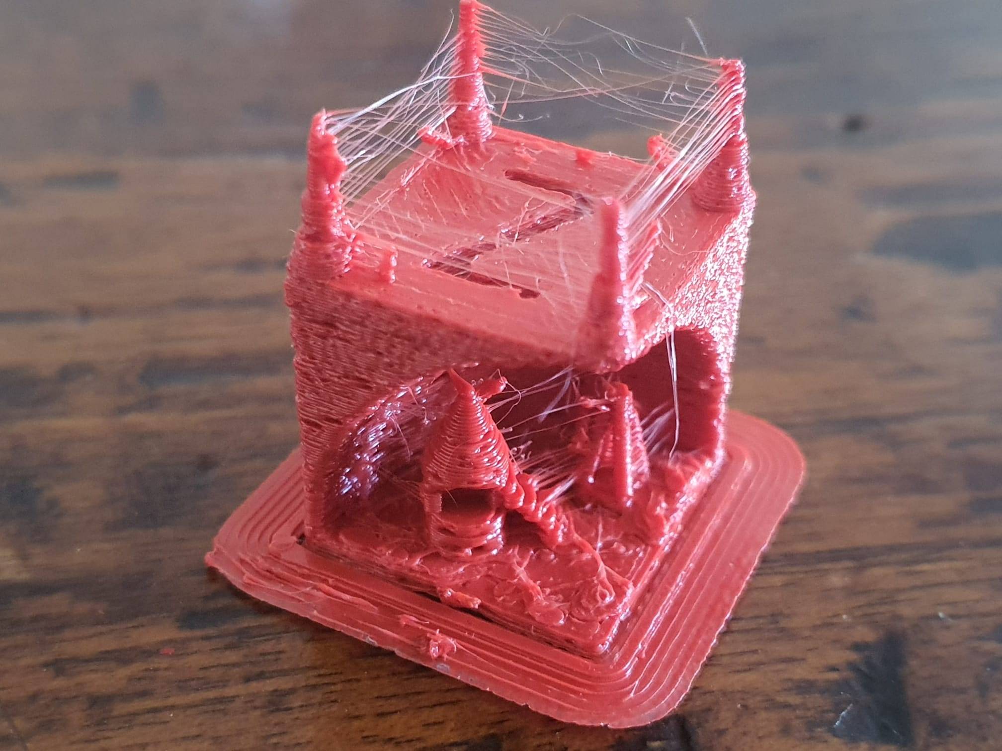
So- what do you think is wrong with this ABS printed testcube after my switch from a standard 0.5 mm nozzle to an 0.6mm Chinese CHT high-flow nozzle?
I did not change anything other than the Curaslicer settings from 0.5mm to 0.6mm and also in Klipper, in the printer.cfg I also changed the setting from 0.5 to 0.6mm nozzle diameter.
Obviously, I also resliced the gcode before printing the testcubes.

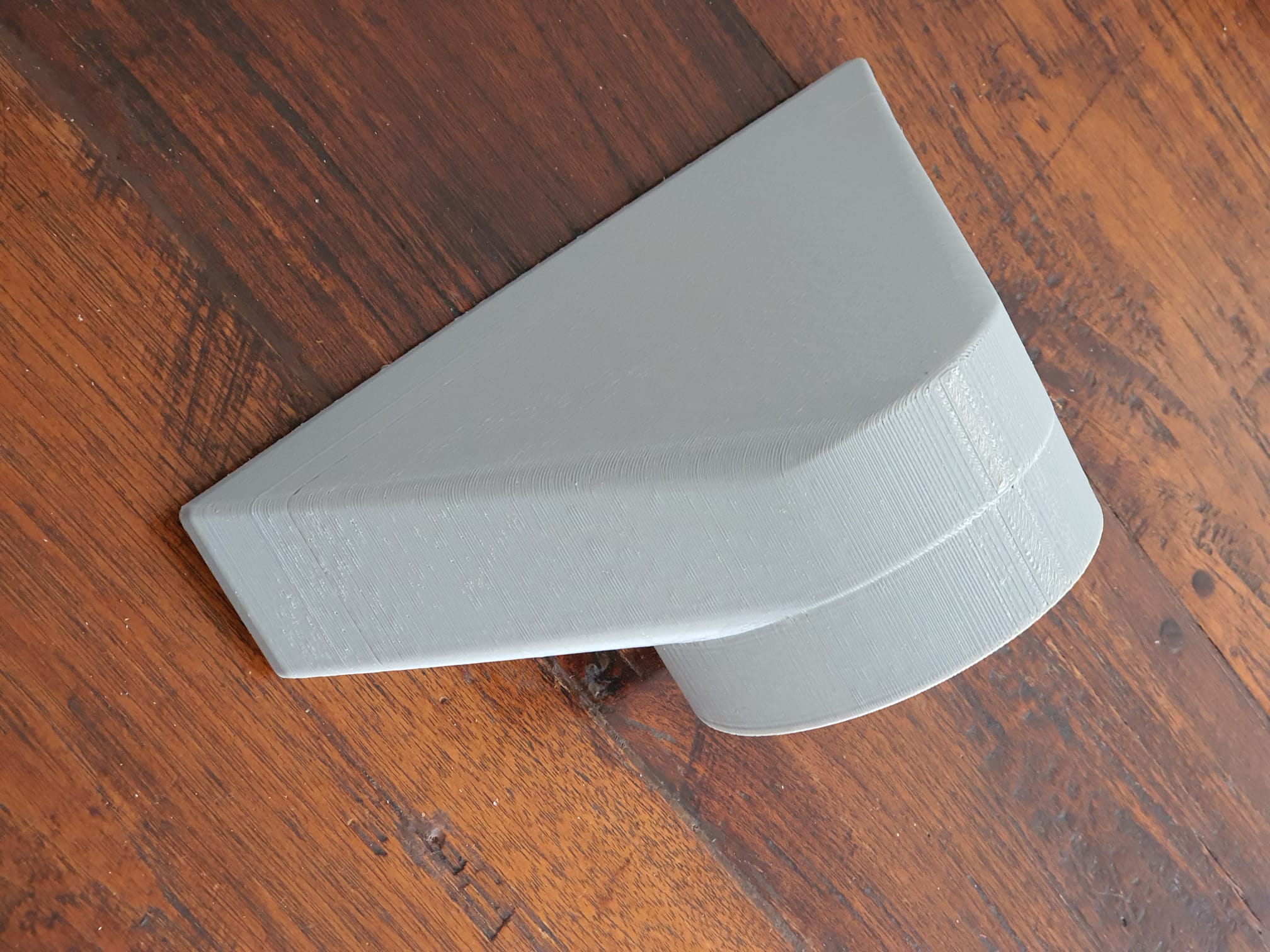
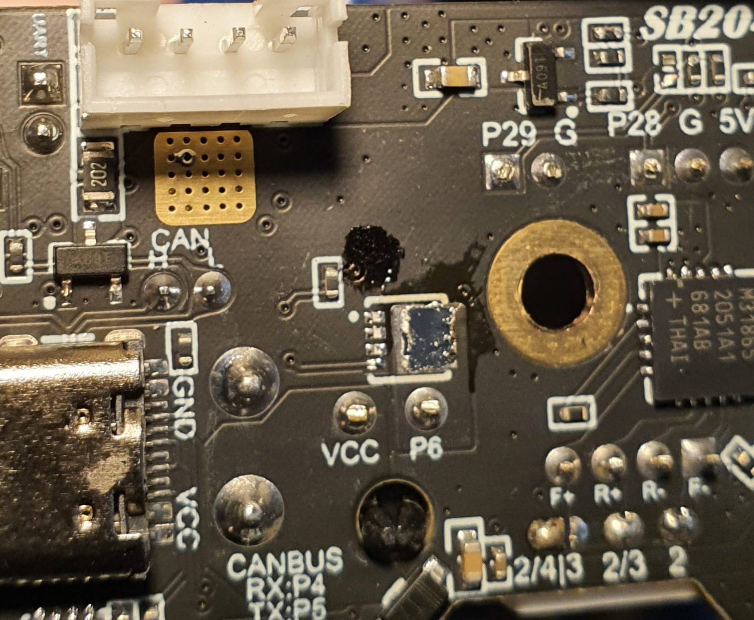
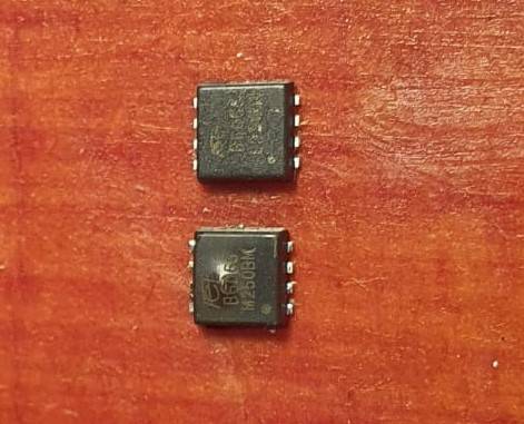
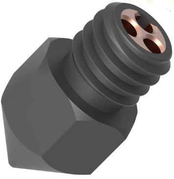
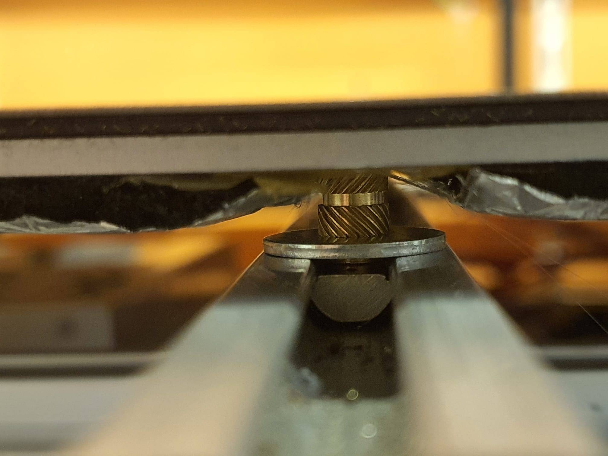
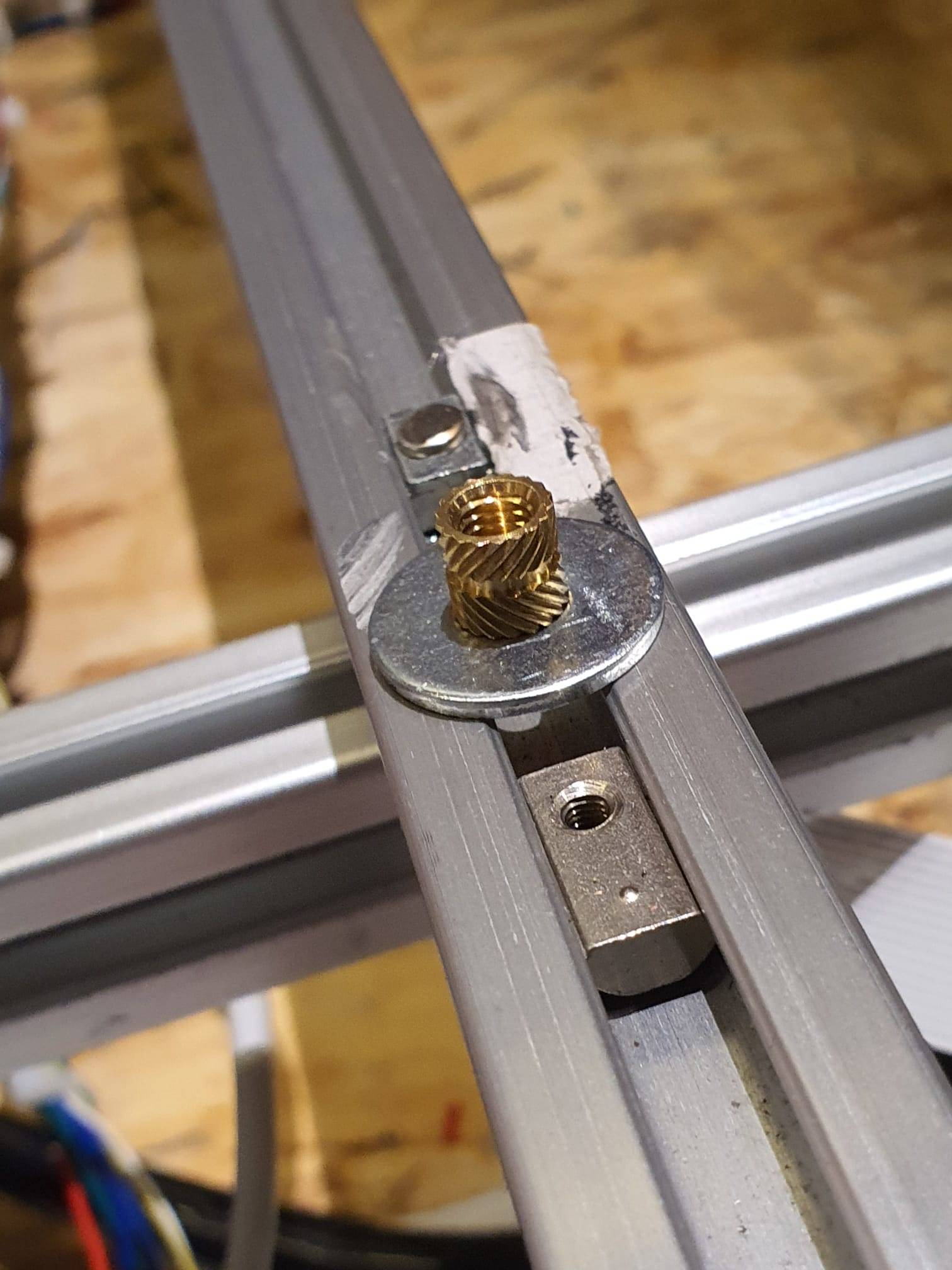
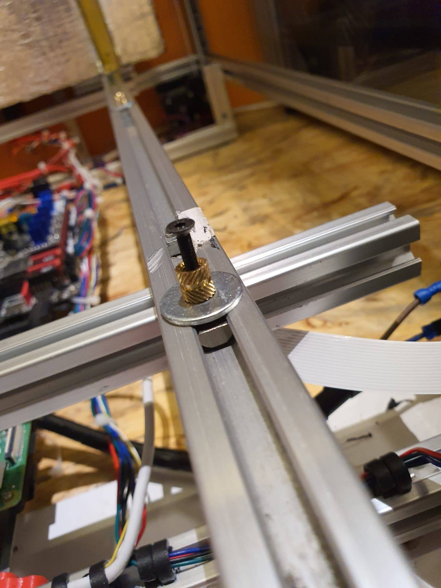
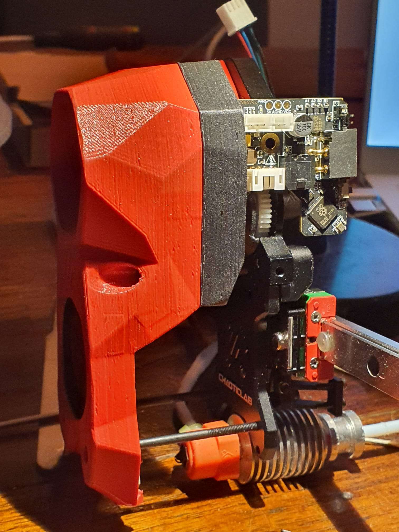
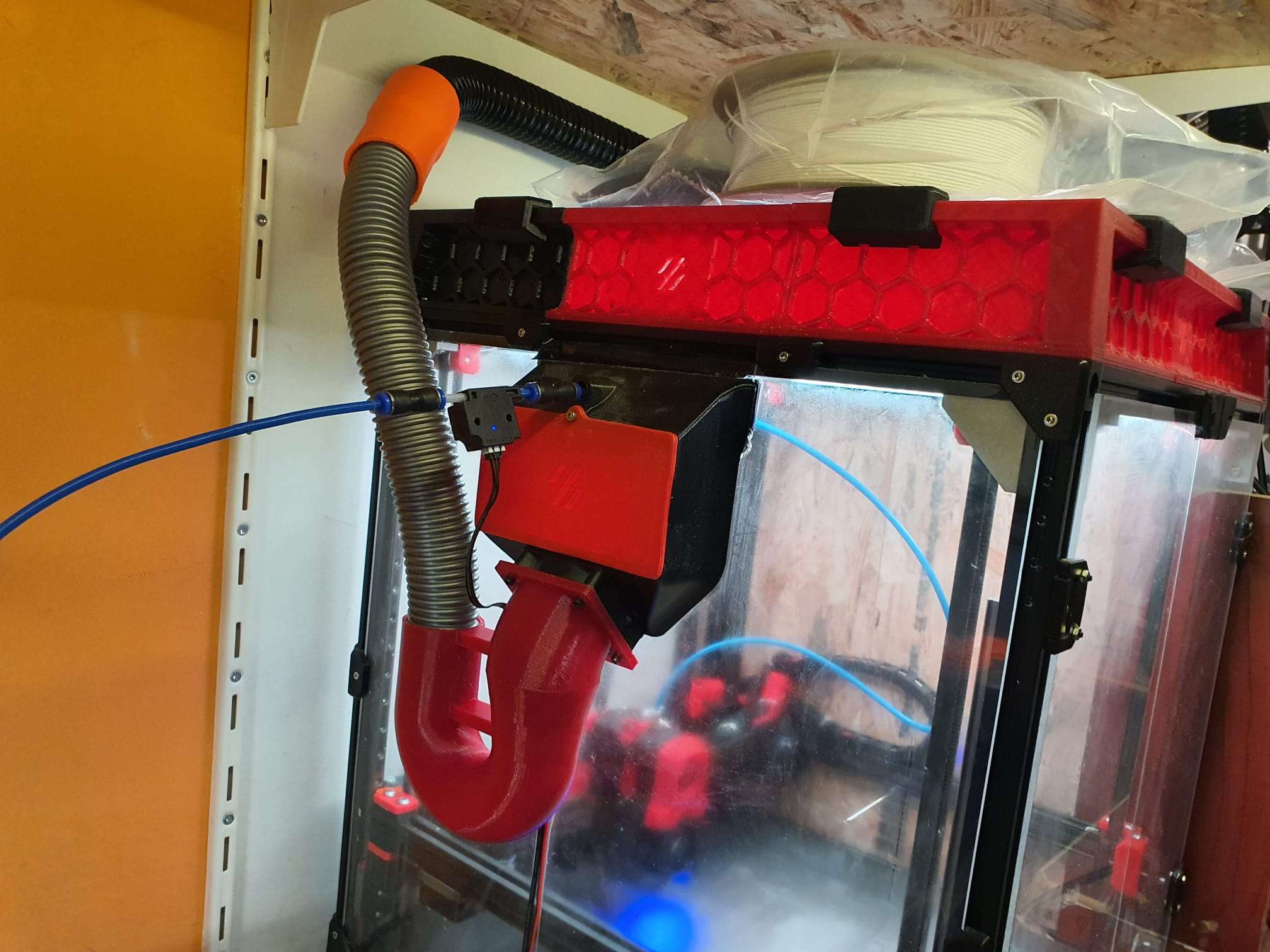
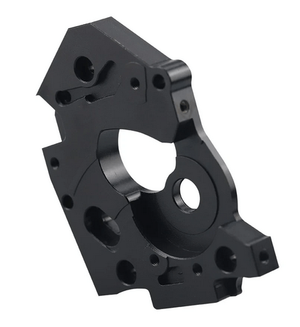
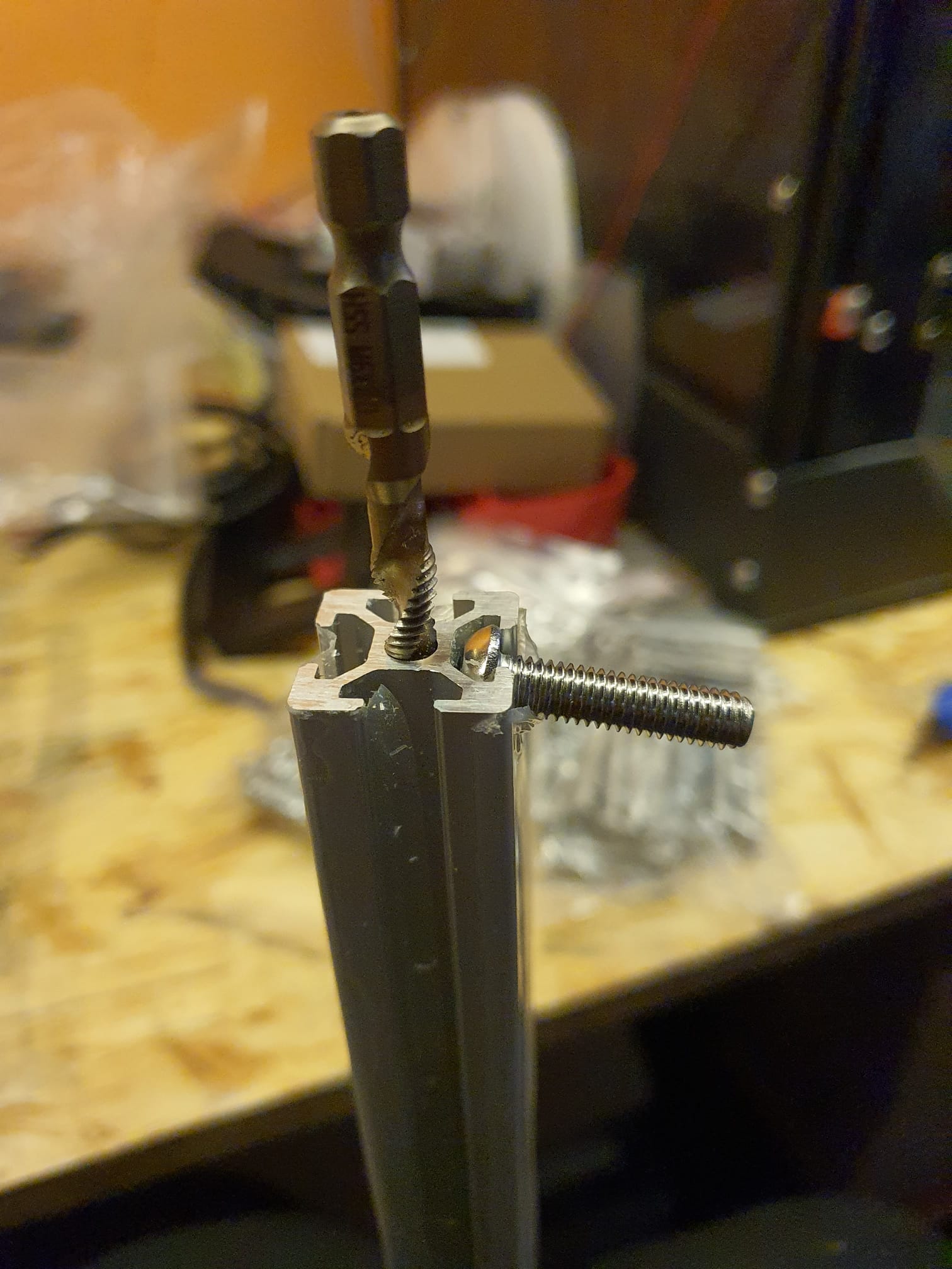
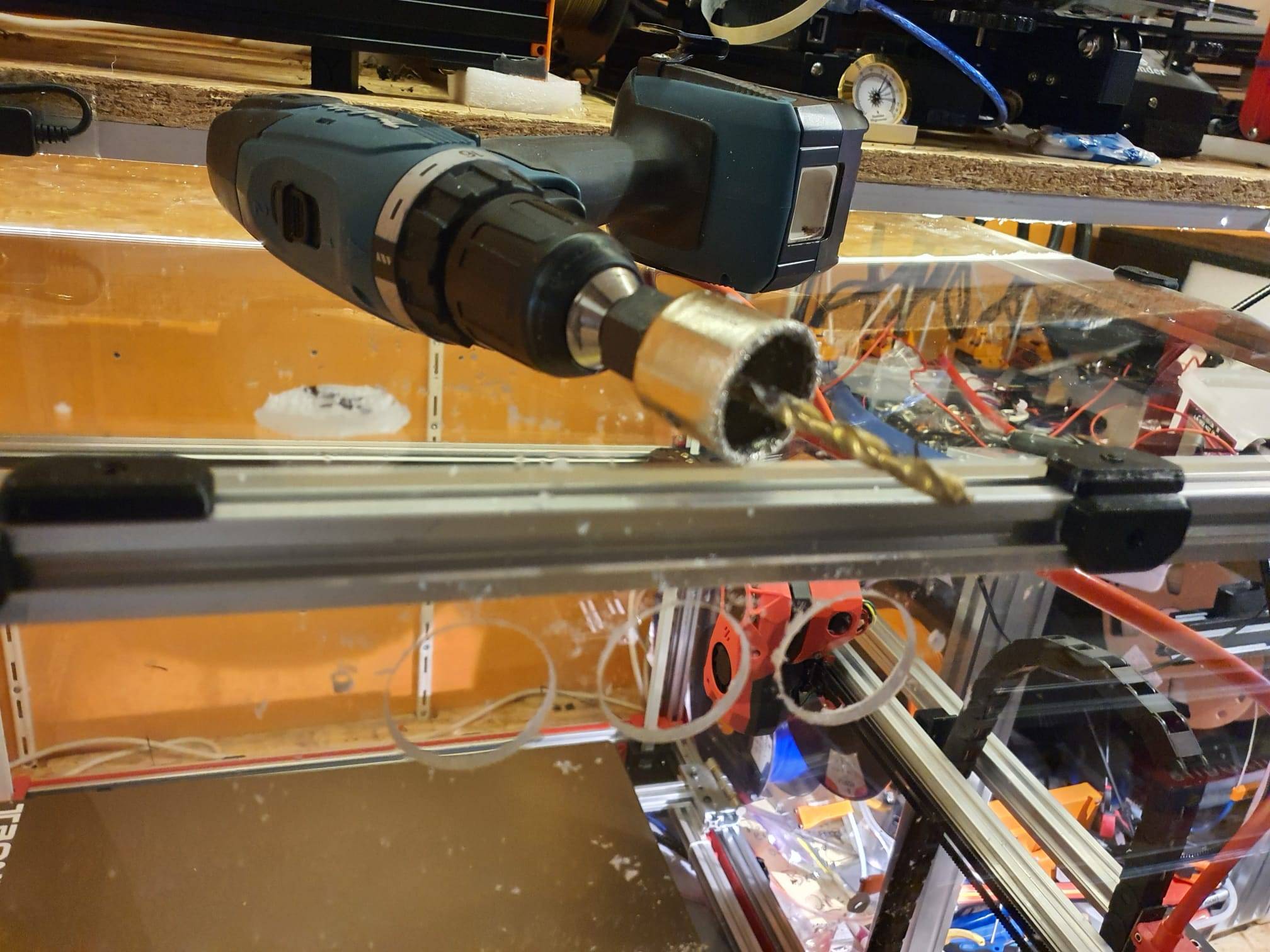
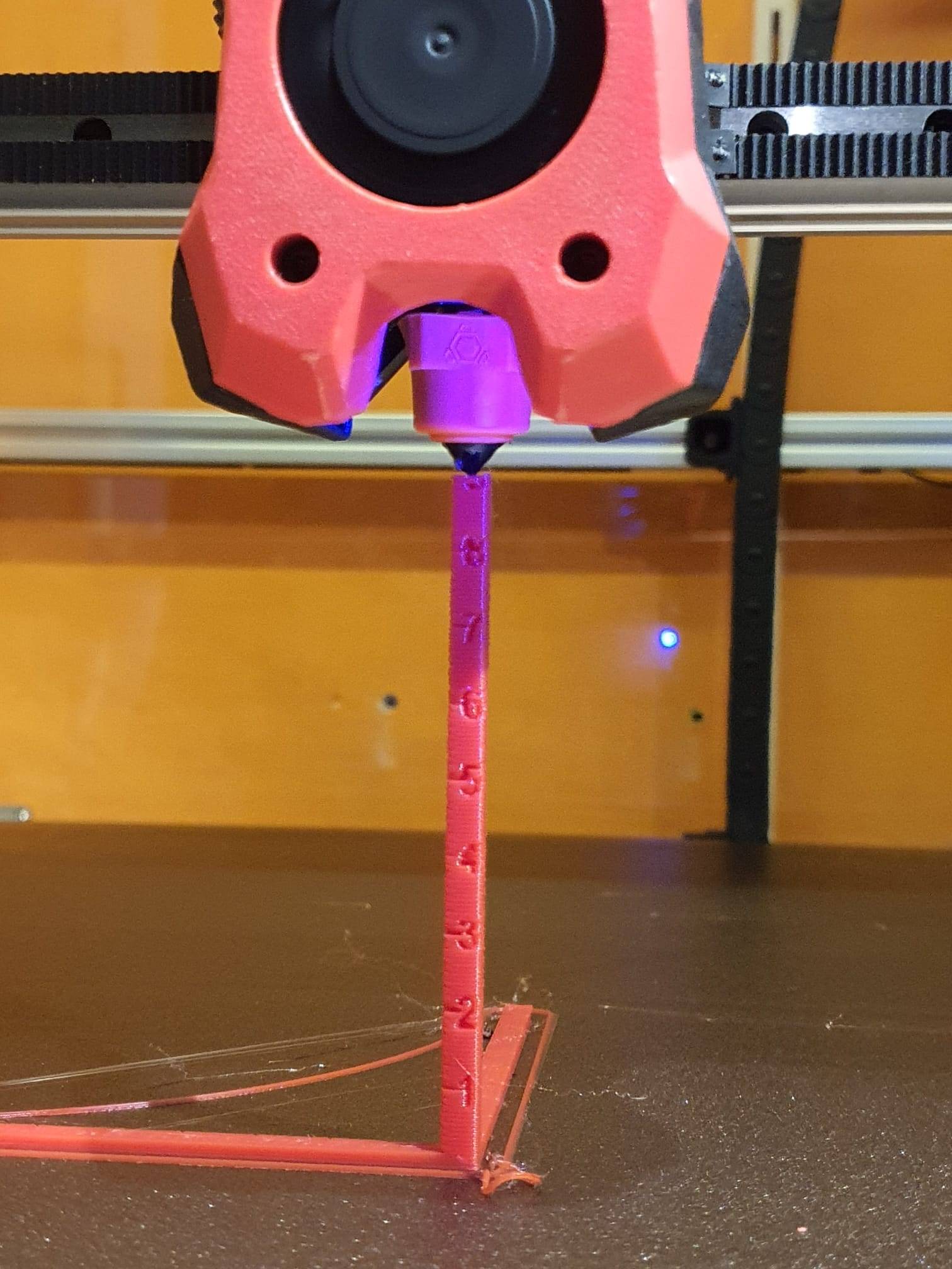
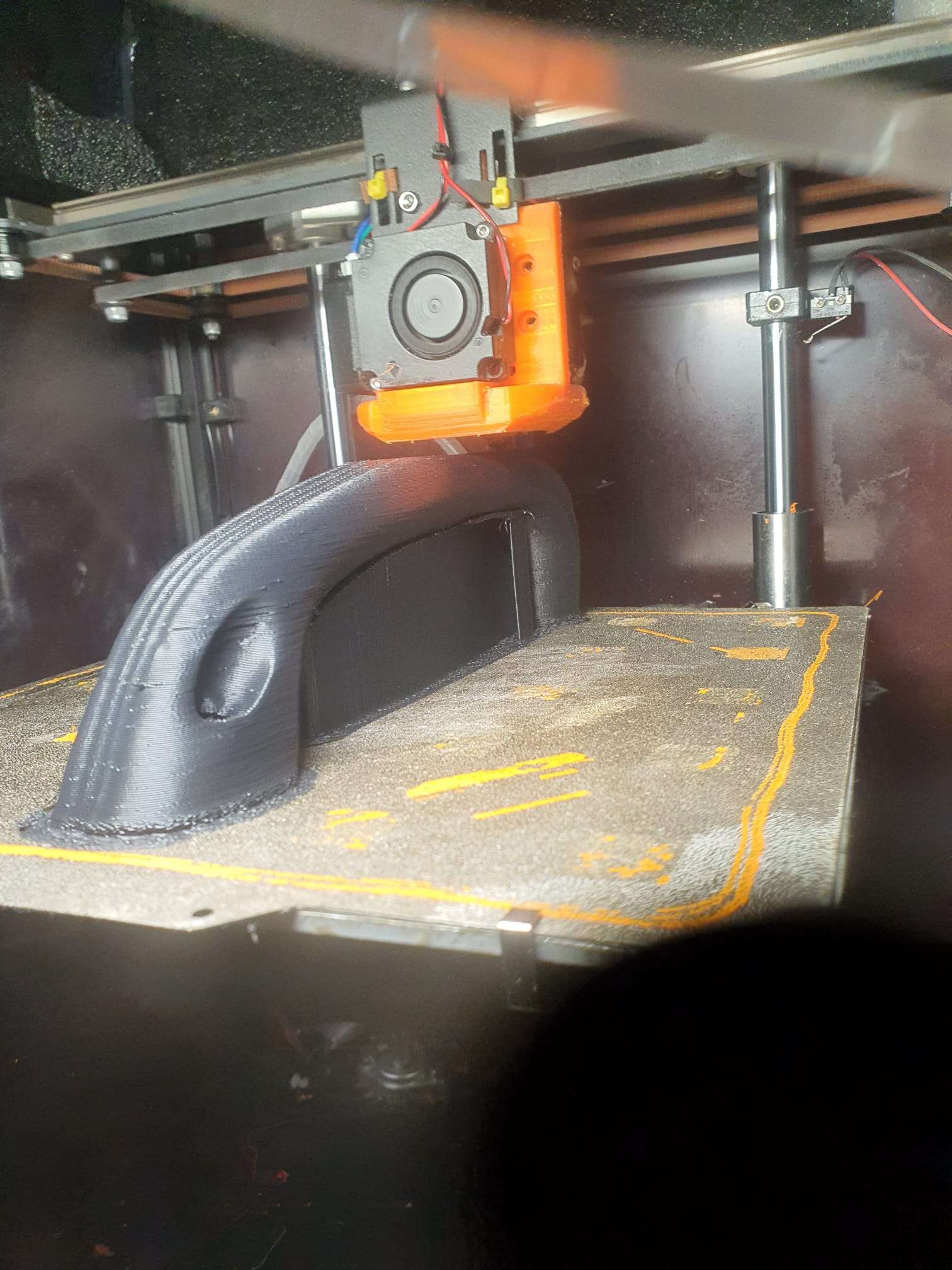
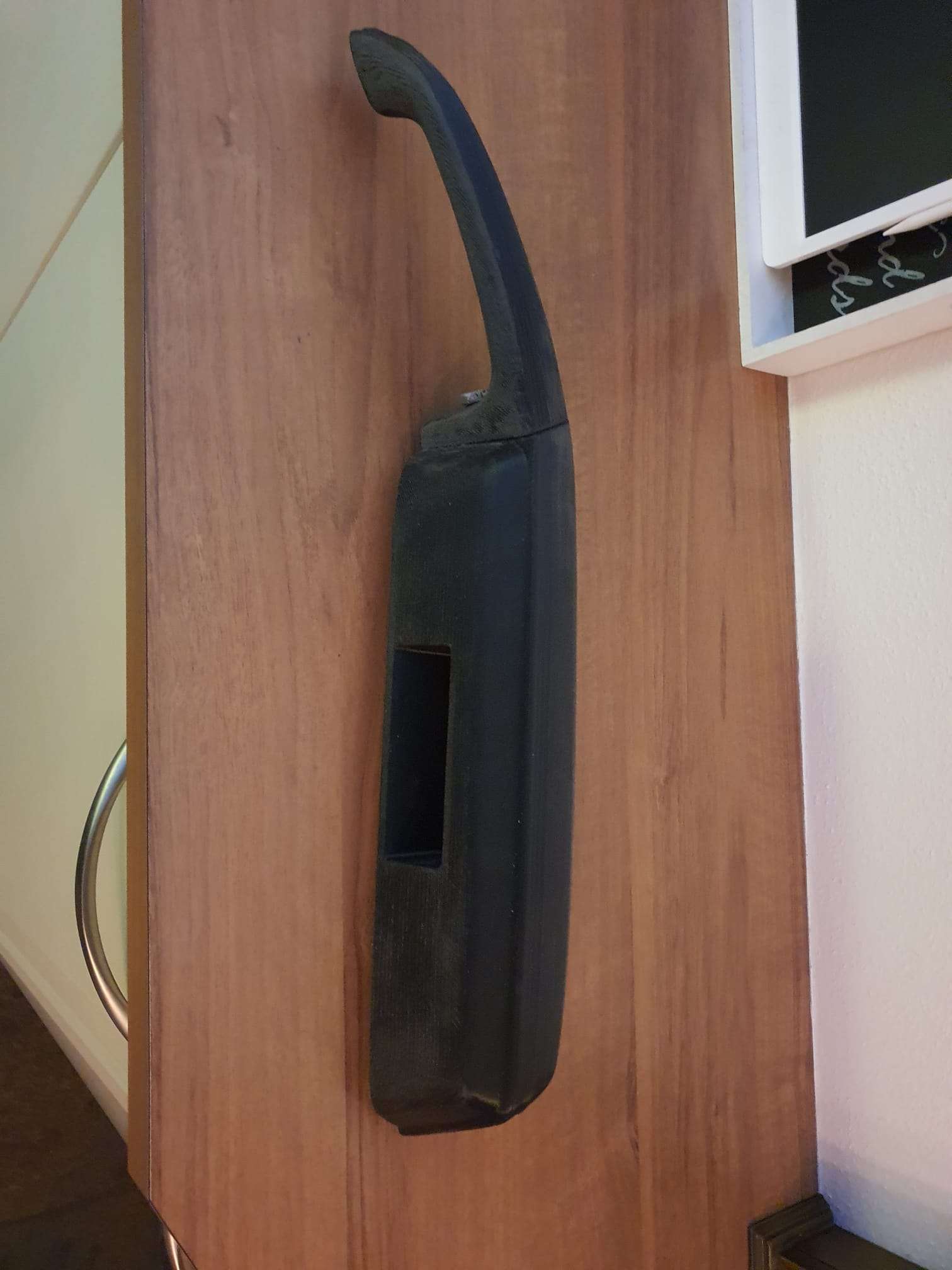
It has been printed on my Voron 2.4R1- 300. with a nozzle as shown in the below picture:

These specific nozzles should be able to produce more flow since the input channel consists out of 3- instead of 1- little hole. The tip is – of course- only 1 hole.
Remedies:
After the failed print, I did the following:
Changed the ABS filament for a fresh pack. No change.
I checked the retraction settings in Curaslicer which were just fine, between 0.5 and 1mm.
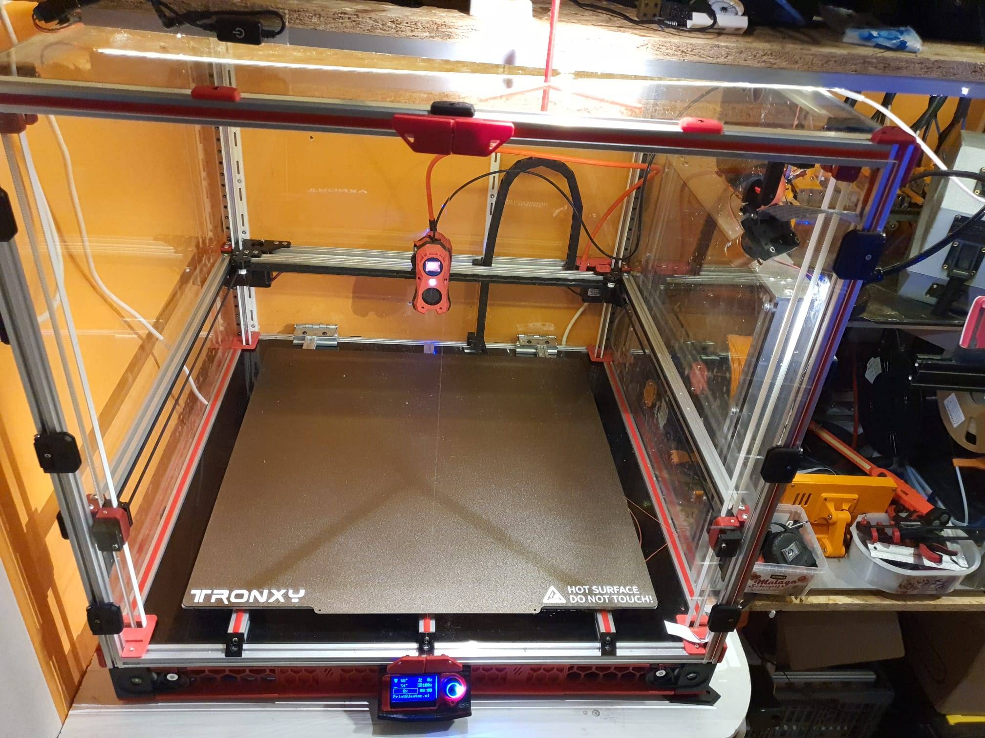
Tested the gcode on my big Voron which also has an 0.6 nozzle and this worked just fine.
So- I checked the input of the filament for drag and it went very difficult. Apparantly something causes drag in the way from the enclosed filament box to the extruder.
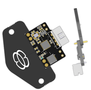
Exchanged the filament sensor because it caused quite some drag and this made some difference in the printed result but not that much.
Checked the extruder and recalibrated this, no change needed. 50 mm extrusion was indeed exactly 50mm filament going in.
All seemed OK but I still got the same blobby outside on the printed testcube.
So- finally I unscrewed the nozzle and- guess what: It is an 0.8 mm nozzle which came in the same small plastic bag along with all of my ordered 0.6 mm nozzles. Should have checked this beforehand, obviously!
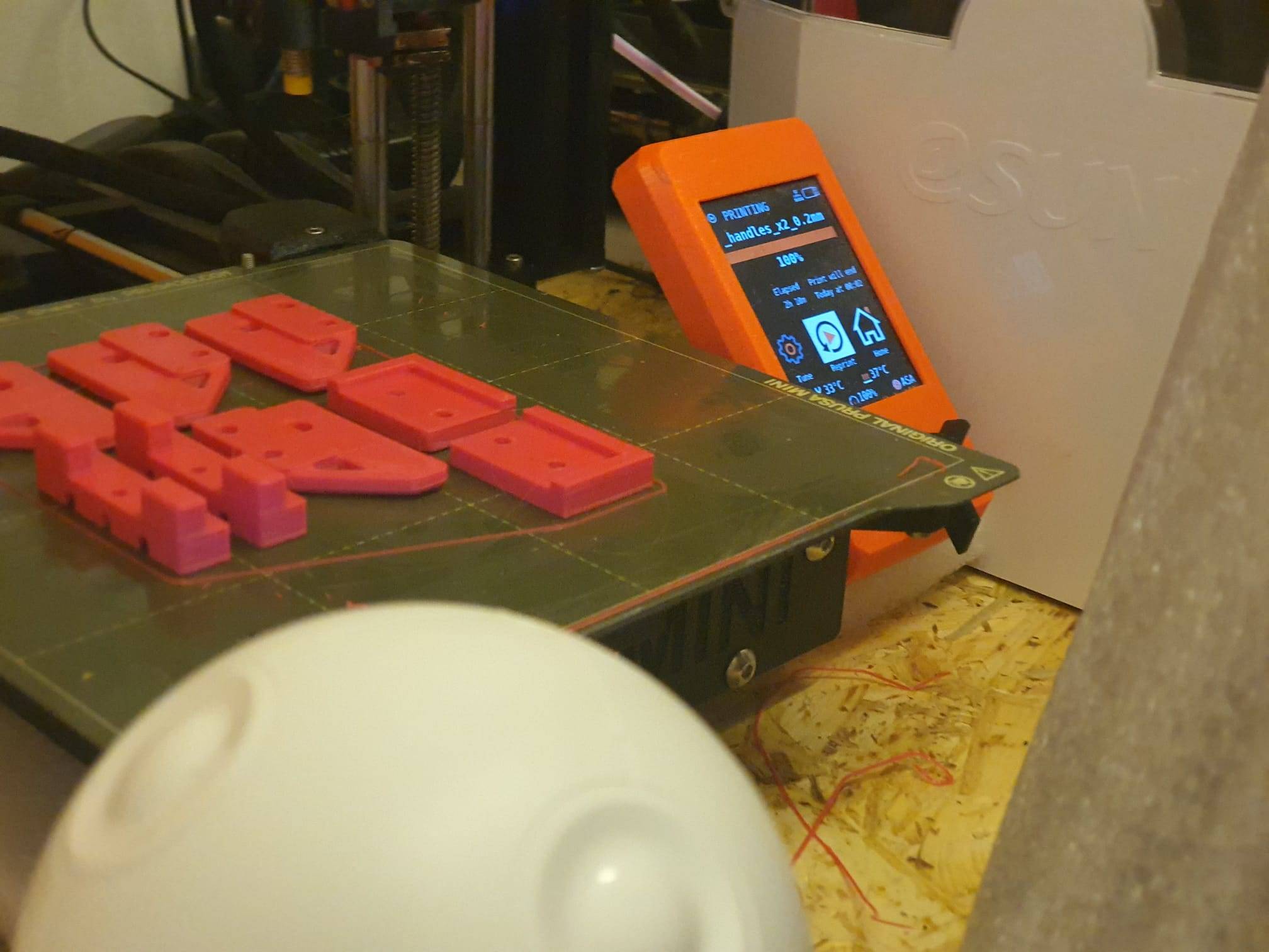
Put a new Chinese CHT 0.6 mm nozzle in from the bag and now ALL IS ALMOST WELL! at least- a lot better.. AND the prints are pretty well usable,
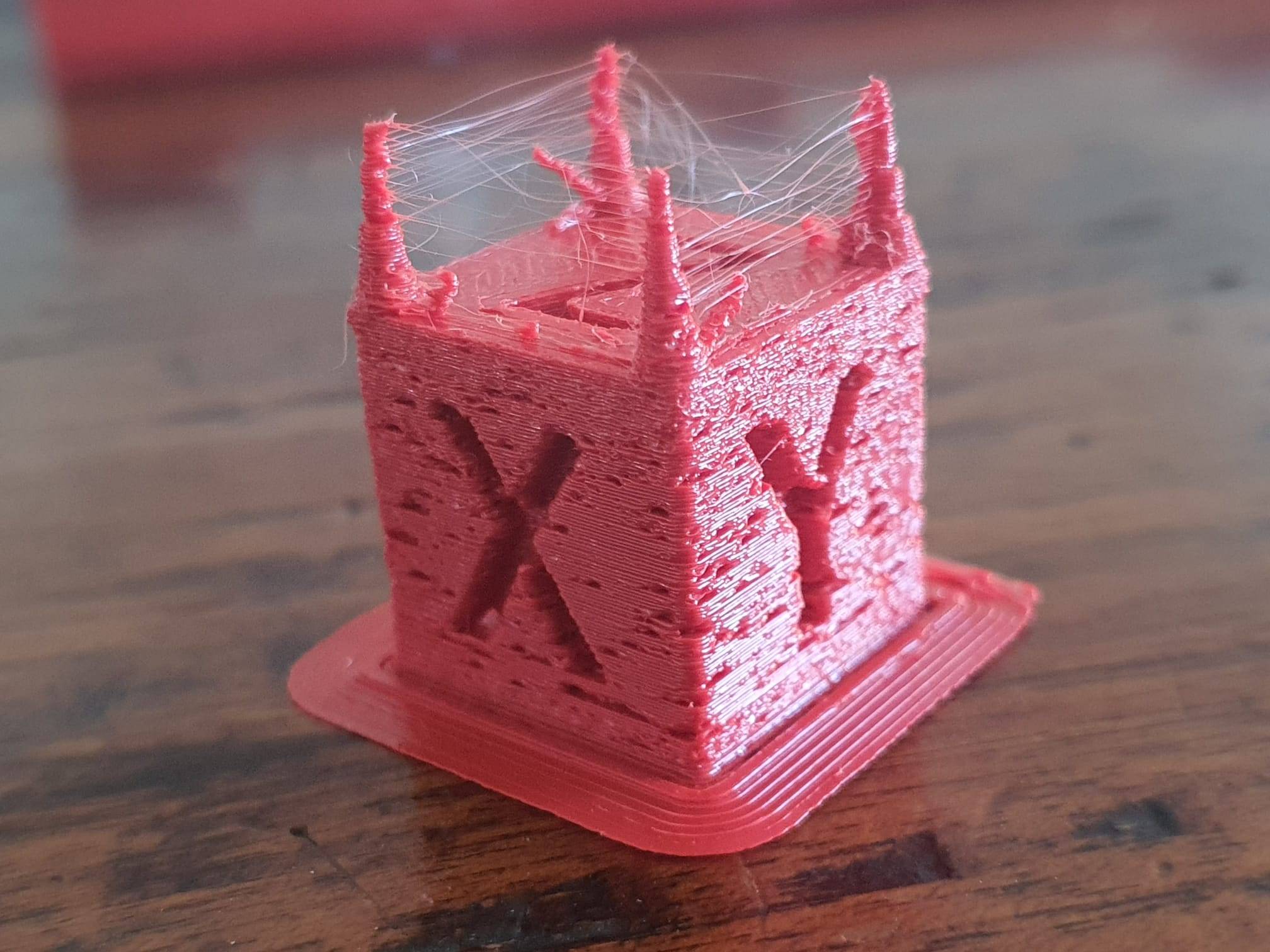
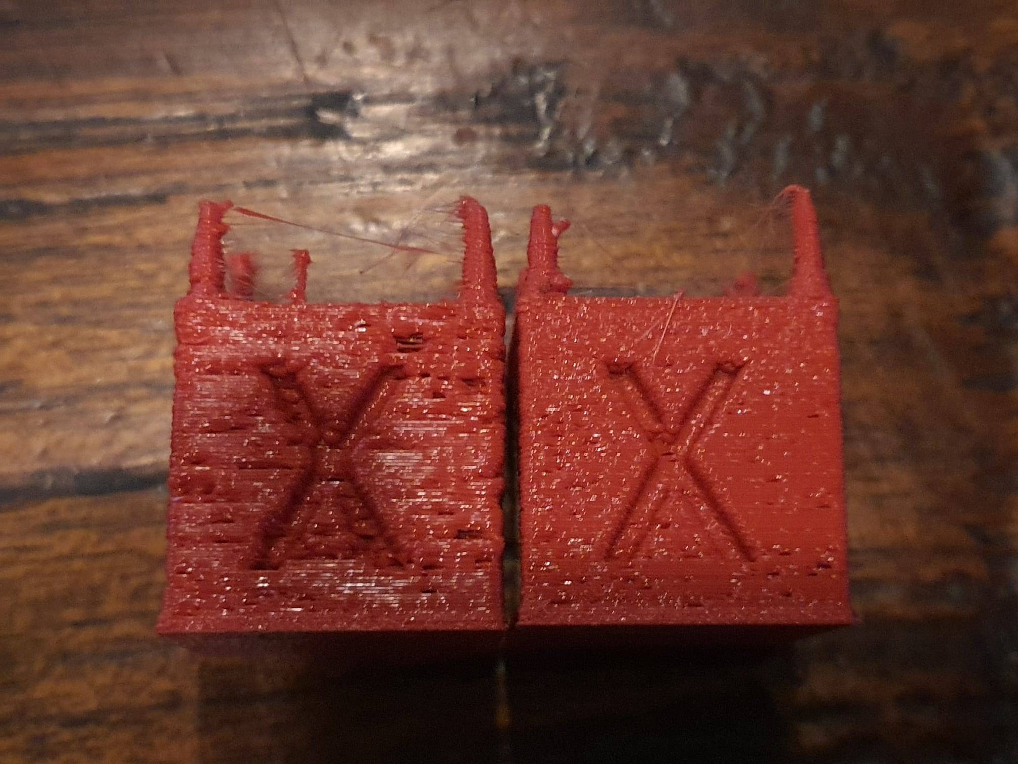
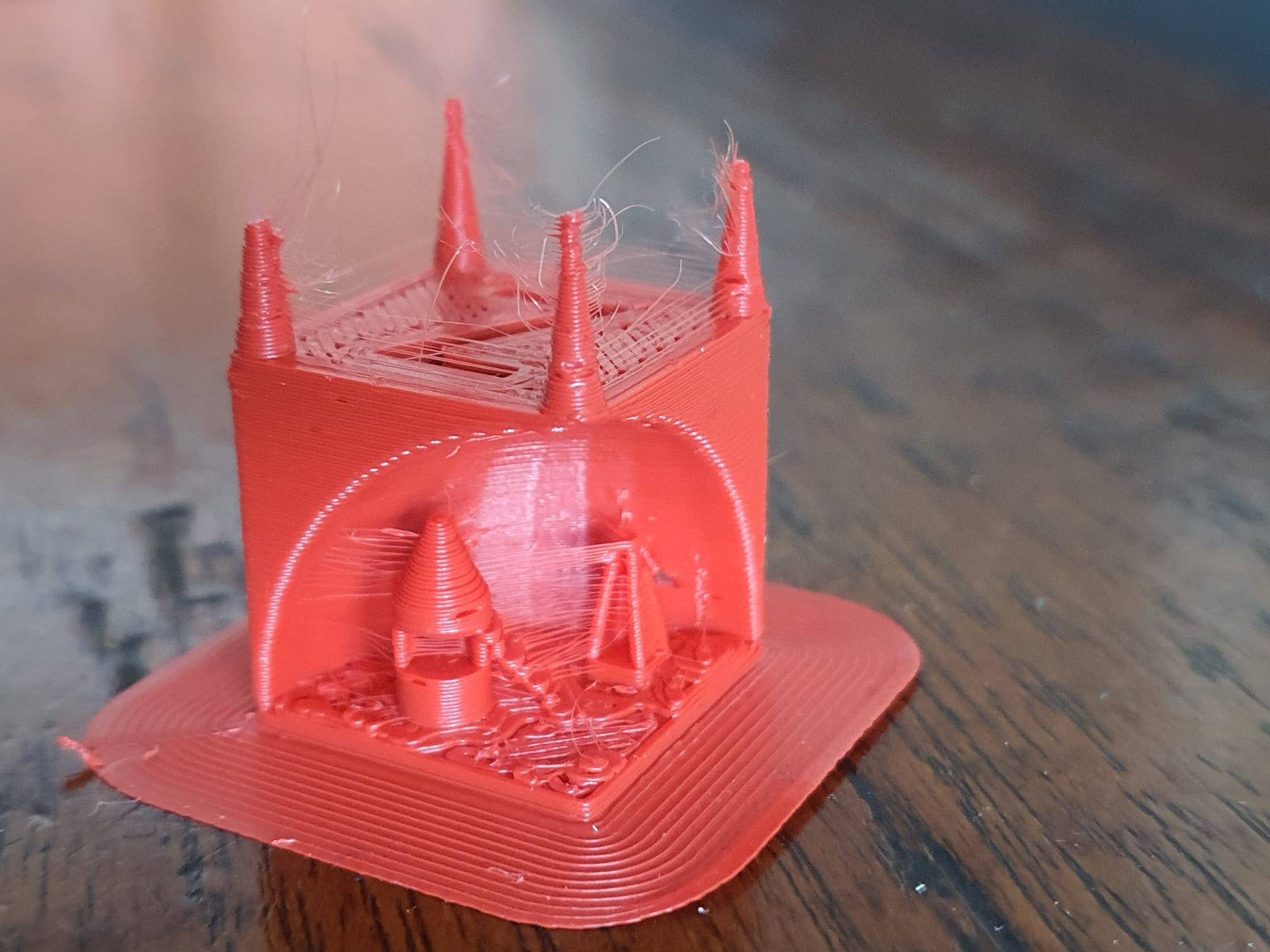
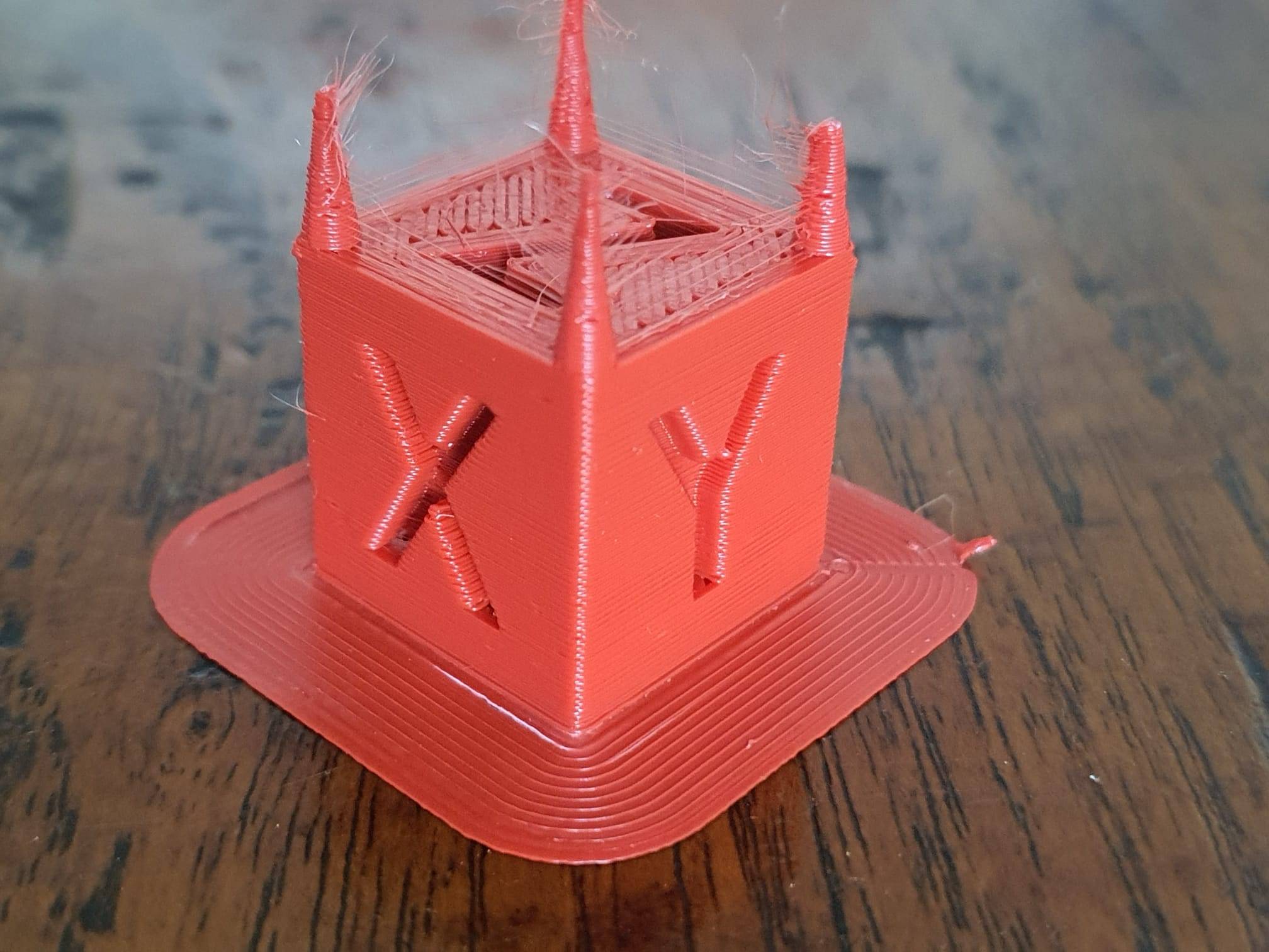
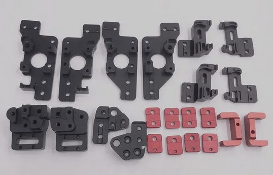
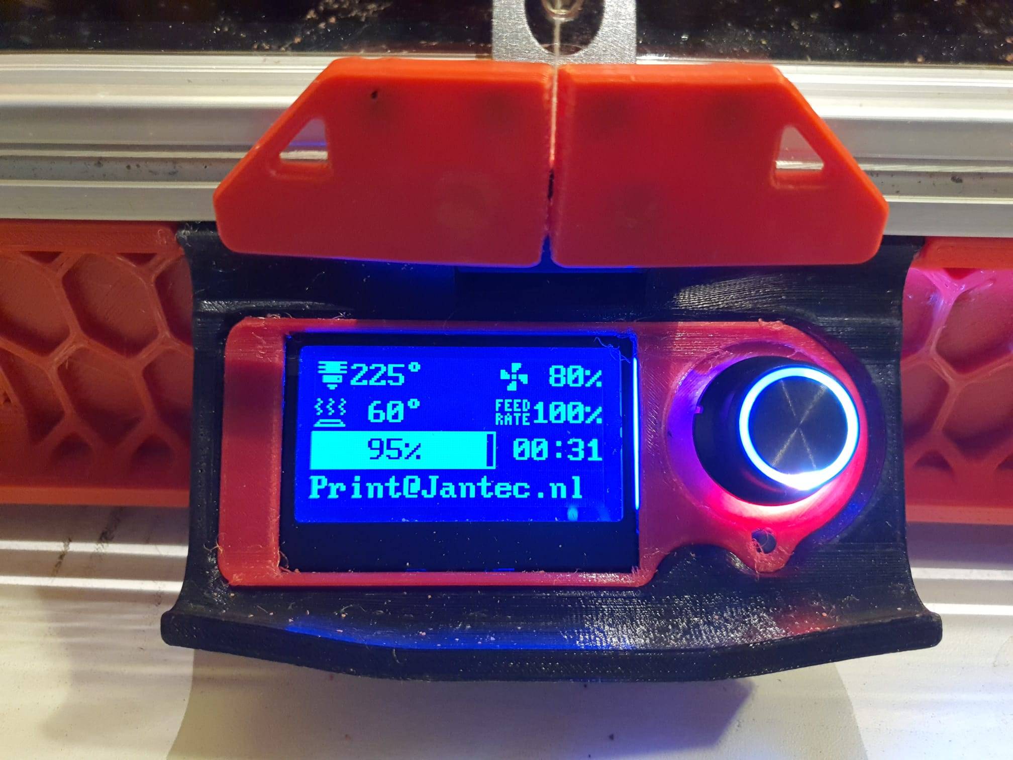
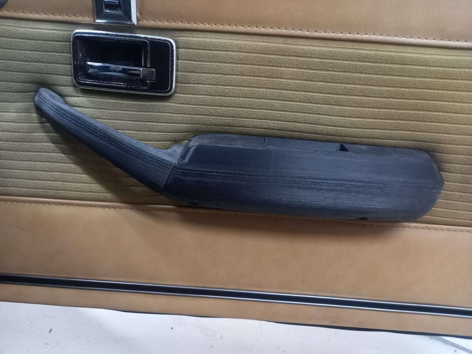
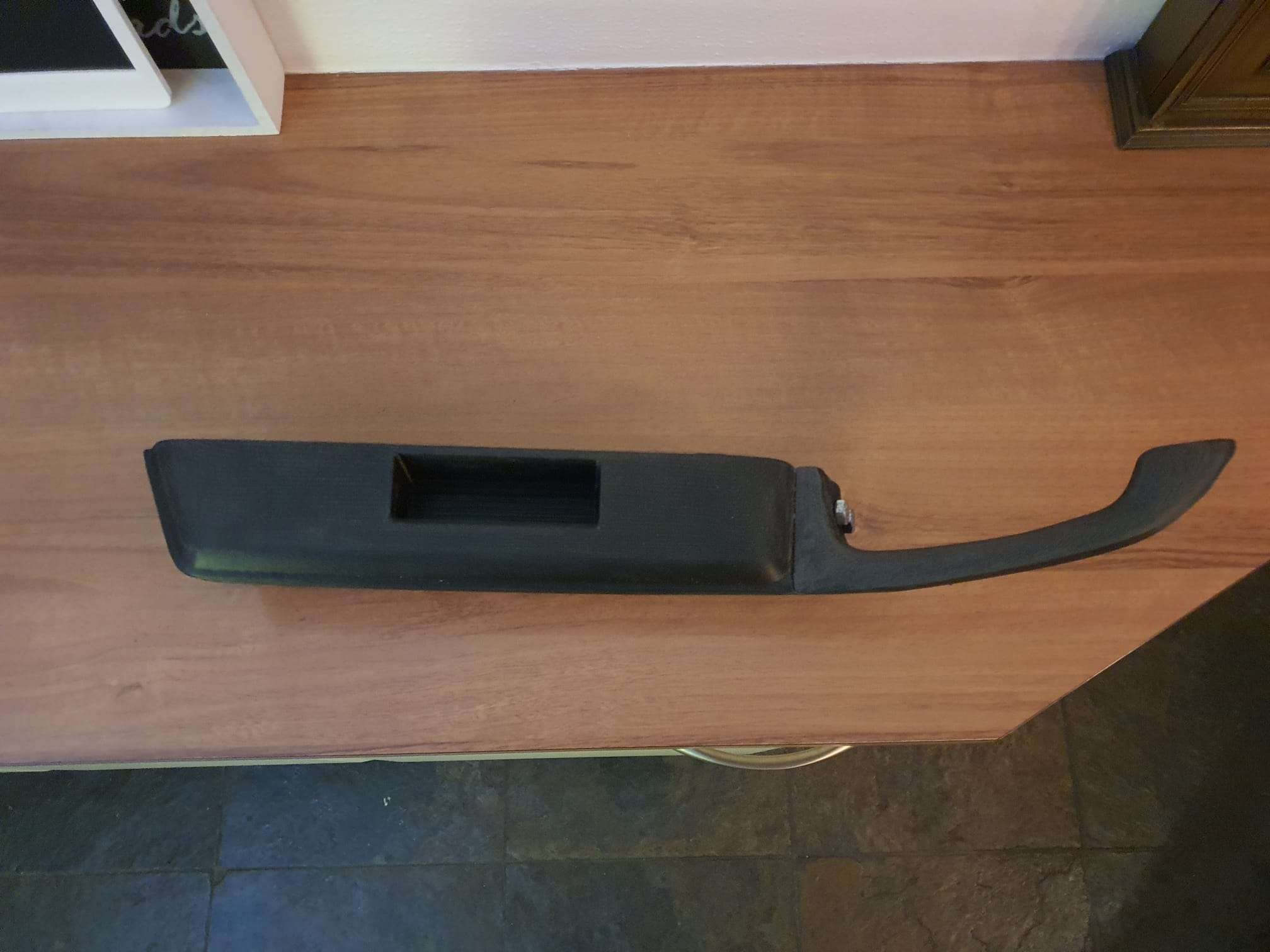
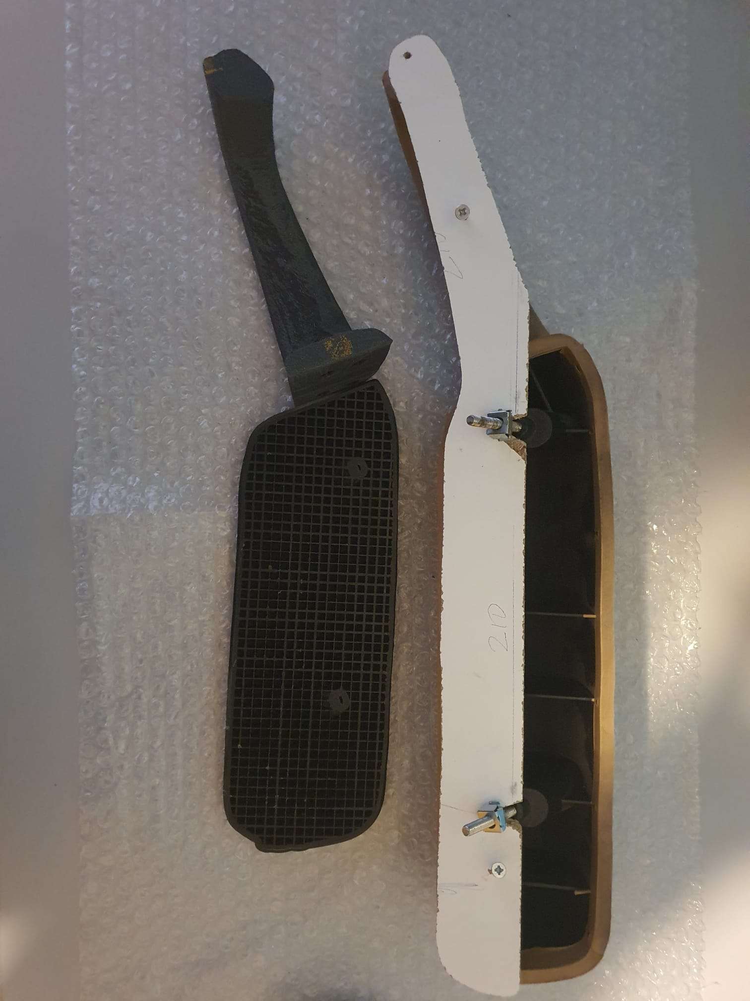
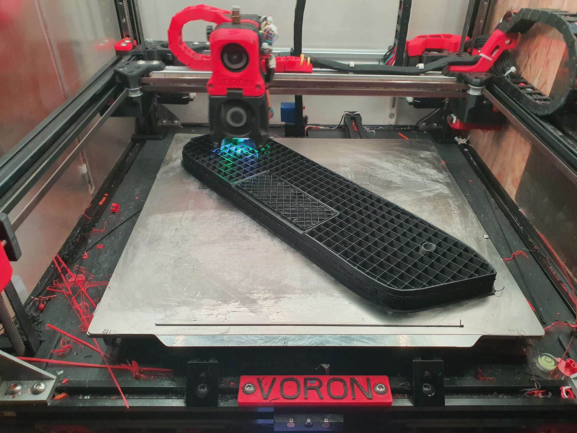
Both pictures: Voron 2.4 printing ABS at 280 degrees, Cura and Klipper setting for an 0.6mm nozzle. Left has an 0.8mm nozzle mounted, on the right is an 0.6mm nozzle mounted, Both nozzles are the high-flow ‘CHT’ Chinese nozzle versions with 3 internal flow channels.I quickly printed a couple of red ABS parts that I need for my big Voron 2.4R2-600.
Small remaining problem: fuzzy X- and Y- walls
I am still working on the blobby surface, as is shown in the above picture, the right positioned testcube. Will try with some other filament! It is not the fuzzy skin option, by the way. It might be related to the high temperature that I use with this particular ABS filament, depending on the application I go up to 280 degrees. Best to try this first with PLA on 180-190 degrees, I guess.
Just got a so-called bright idea- Could it just be that I always had the temp for my extuder way too high and that such a high temp due to the better nozzle with more flow- is no longer required?
That might explain why the prints are now perfect and shiny- But the X an Y walls are somewhat blurry.
That might be due to the high setting for the extruder ‘s temperature.
I could also try to set the print fan on, or at least higher than my usual 25% for ABS.
Then I can see what the impact is, or just lower the extruder temp from 285 to 250 for my red ABS. Give it a shot. Will let you know!
BTW, I never ever had printed this ABS with a shiny XY surface. It was always matte, also at 285 degrees. Possibly the standard nozzle just required a higher temparature setting? I have actually never heard of something like this, we’ll see.
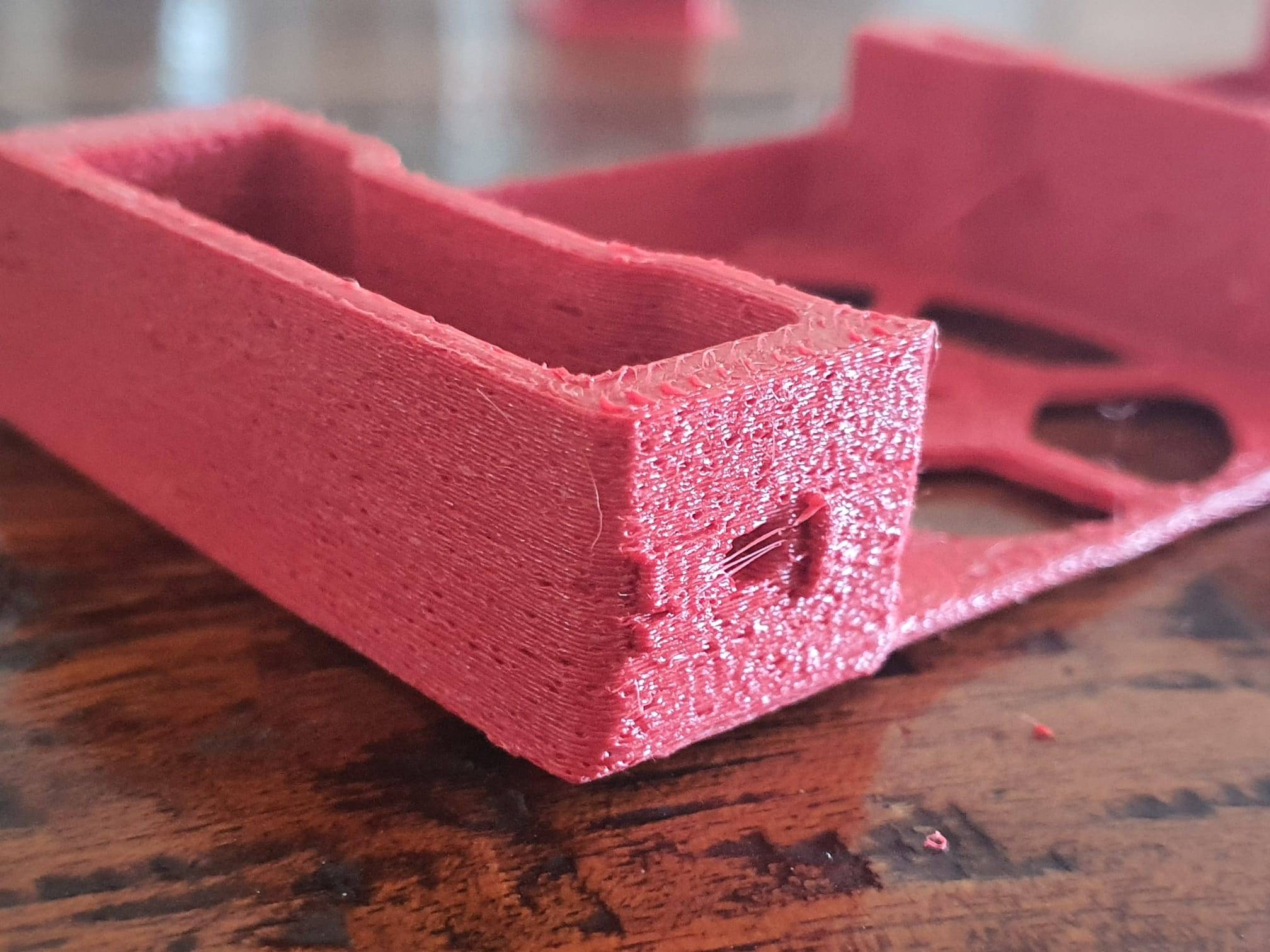
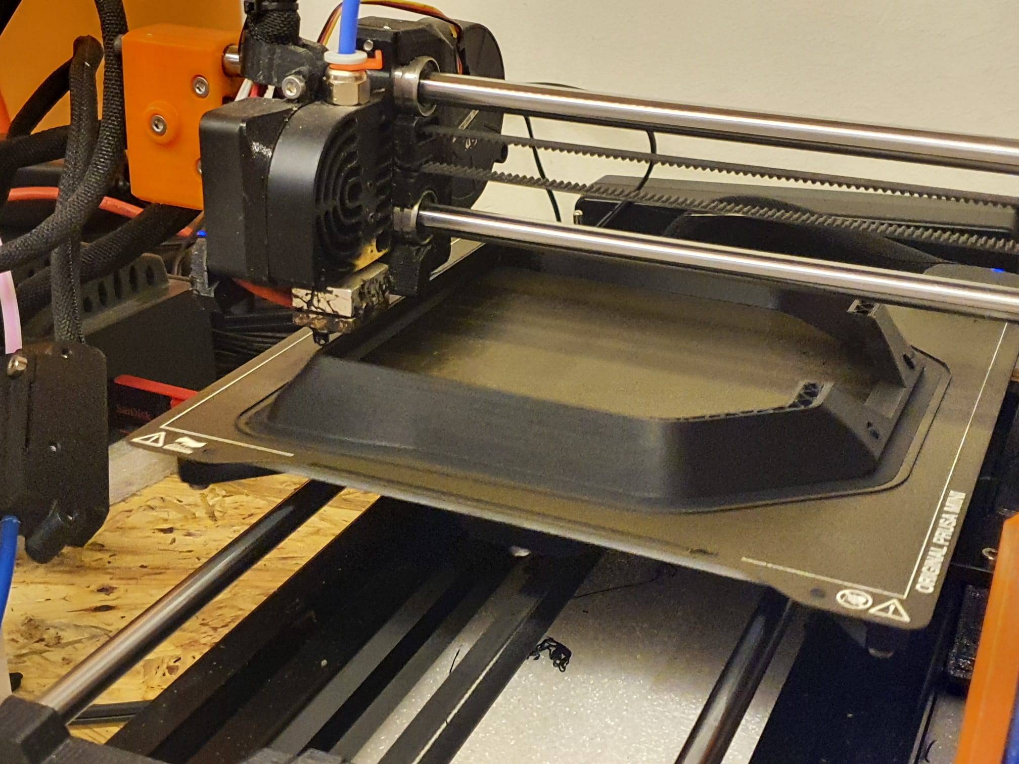
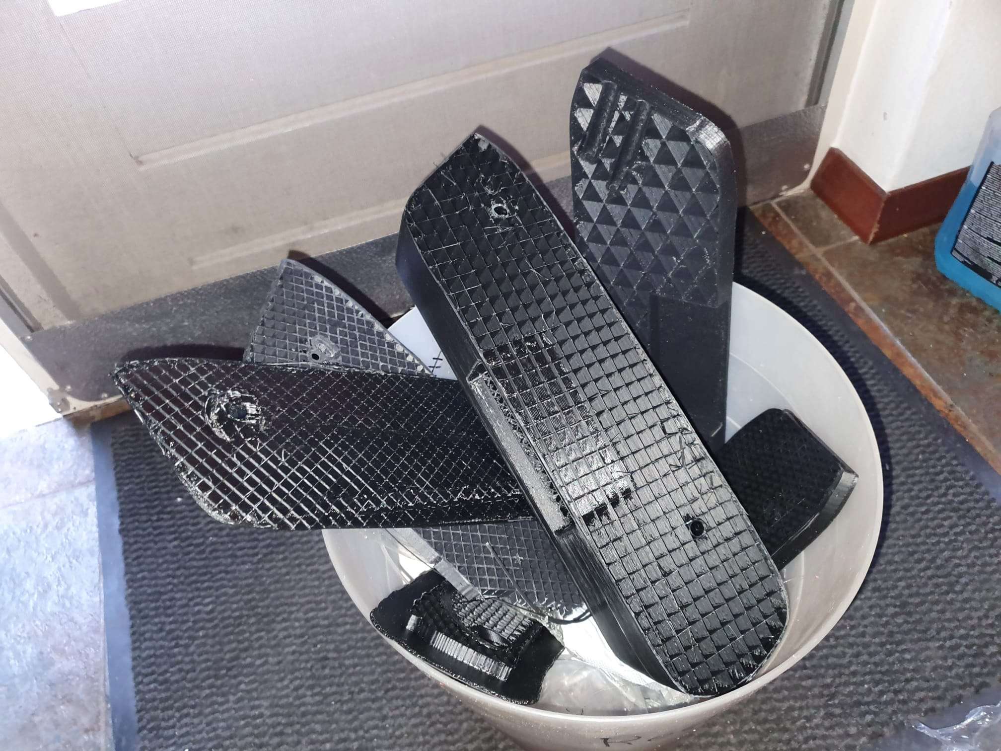
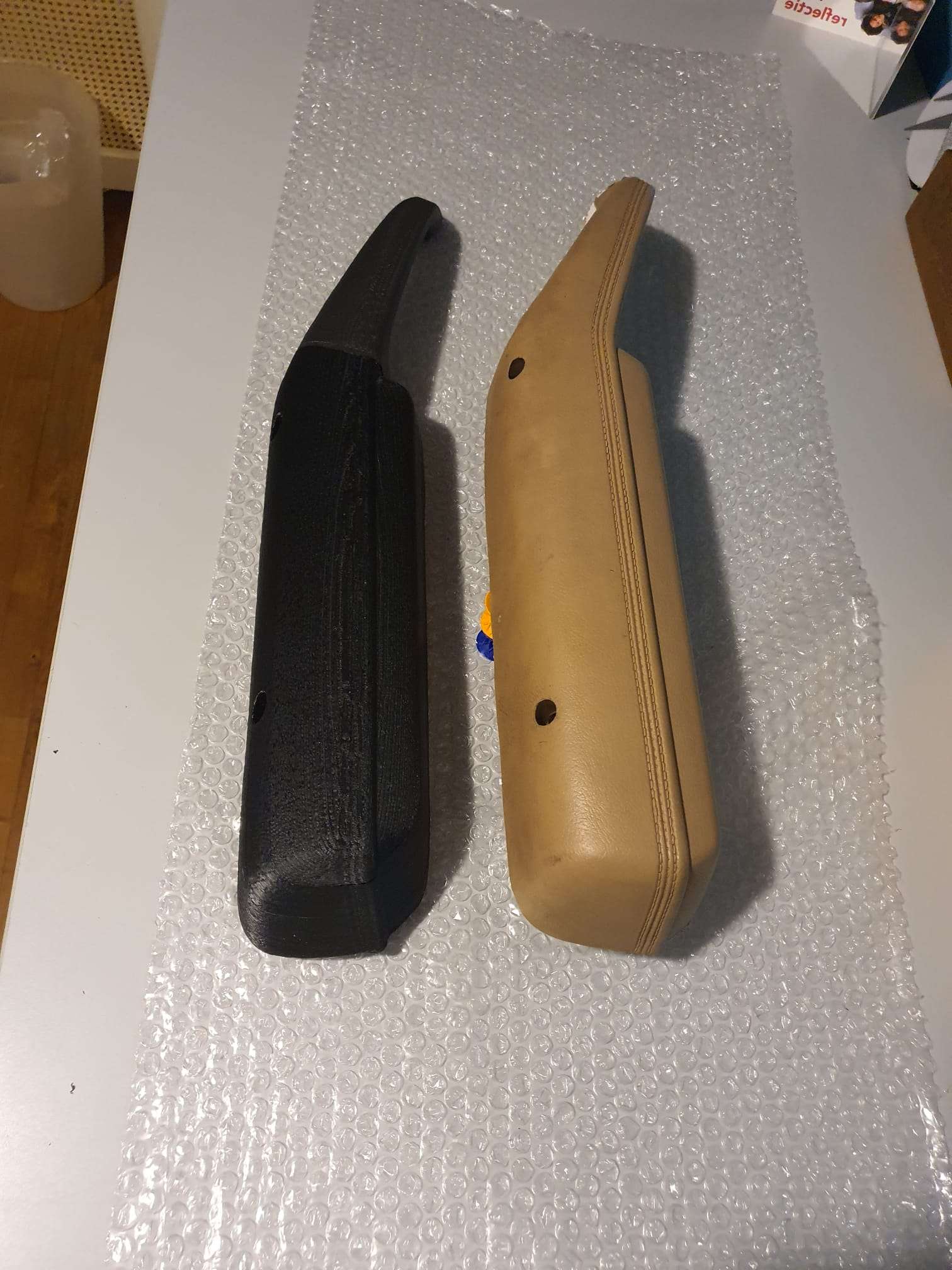
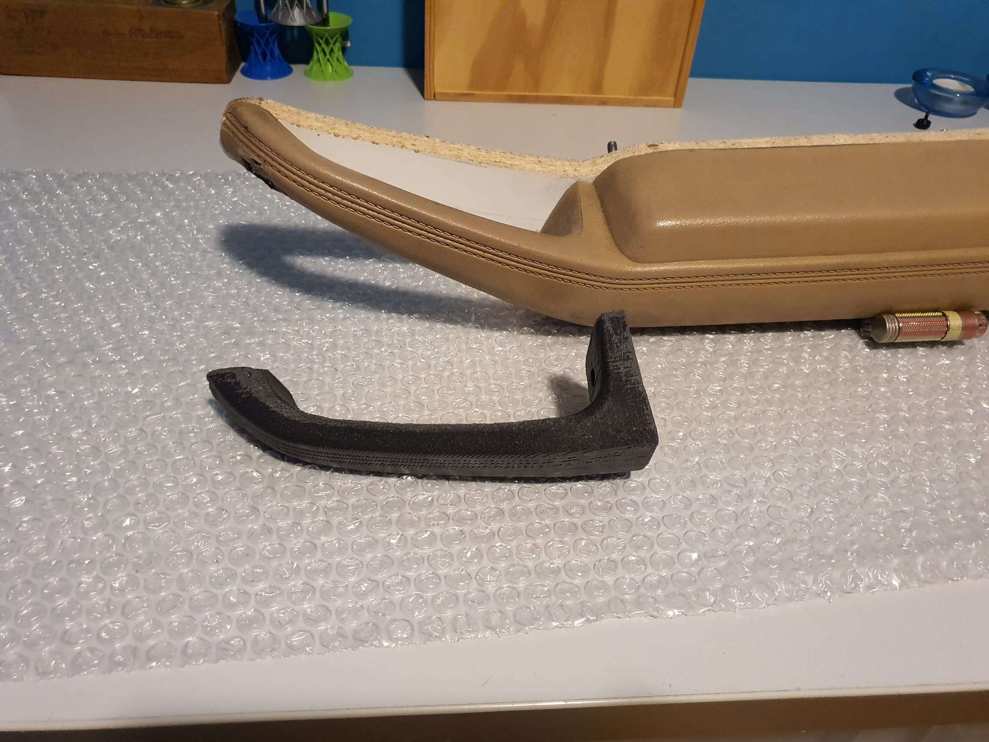
The following 2 pictures show what the printresult was when I printed at 240 degrees, 0.6mm nozzle and all of the rest was unchanged…
The walls printed pretty nice, only the top is not what I want. I will dig into that later.
The sudden stringing when using the high-flow nozzle is obviously one clear indication that I am searching in the right direction for solving my fuzzy walls now. Previously, I never had stringing with the red ABS filament. The stringing was also a lot less when printing this ABS testcube at 240 degrees instead of 285 deg.
I will do a last test with the option to smooth the Z-surface better, will show this here as well! Could also be that the wall width for the top surface is set wrong, we’ll see. Or the temp for final printing too low, or the part-fan a bit too much at 30%?