Please donate $1 to my paypal account if you use (parts of) my designs so I can continue to share nice stuff for you to download
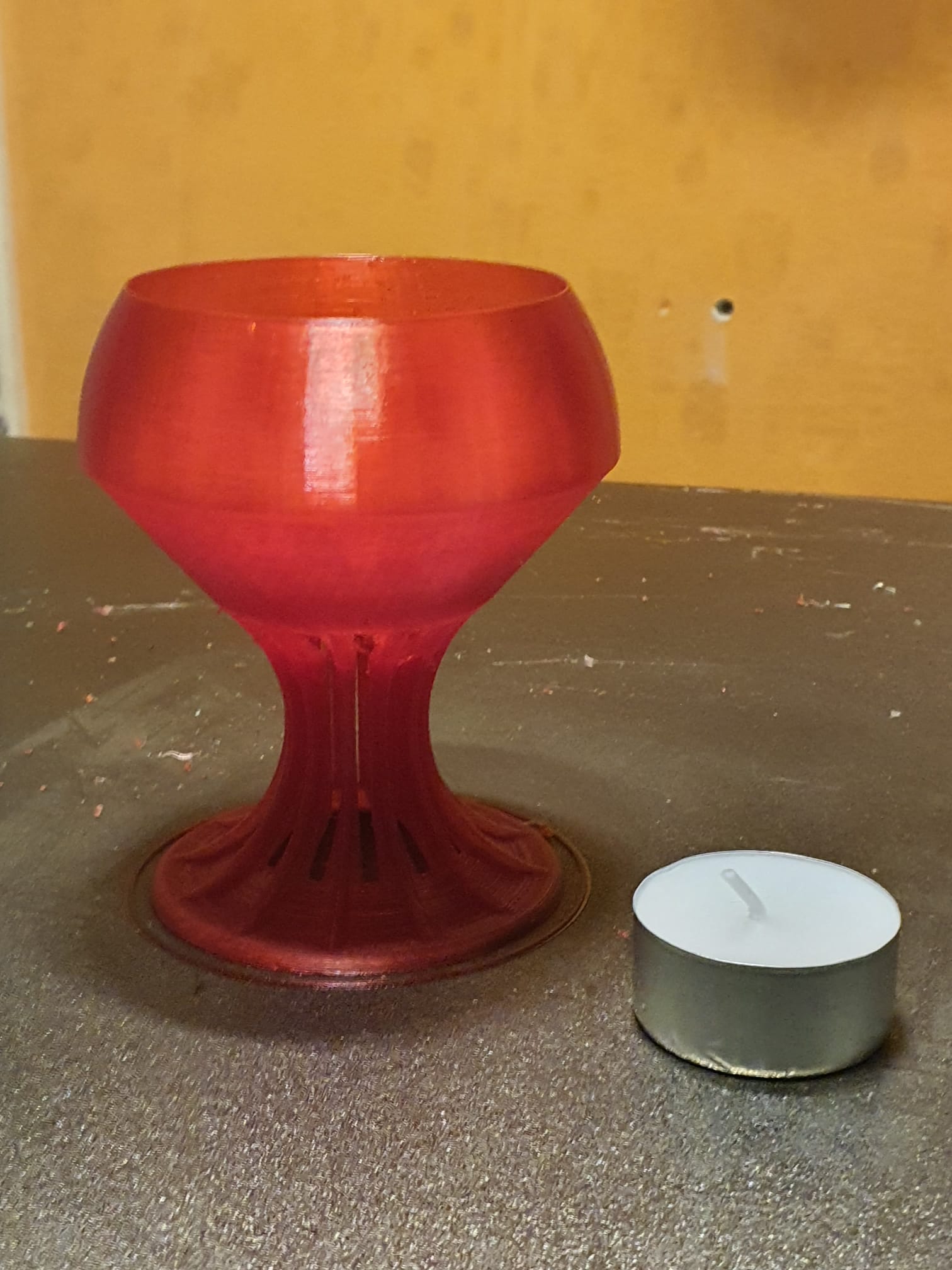
Please donate $1 to my paypal account if you use (parts of) my designs so I can continue to share nice stuff for you to download

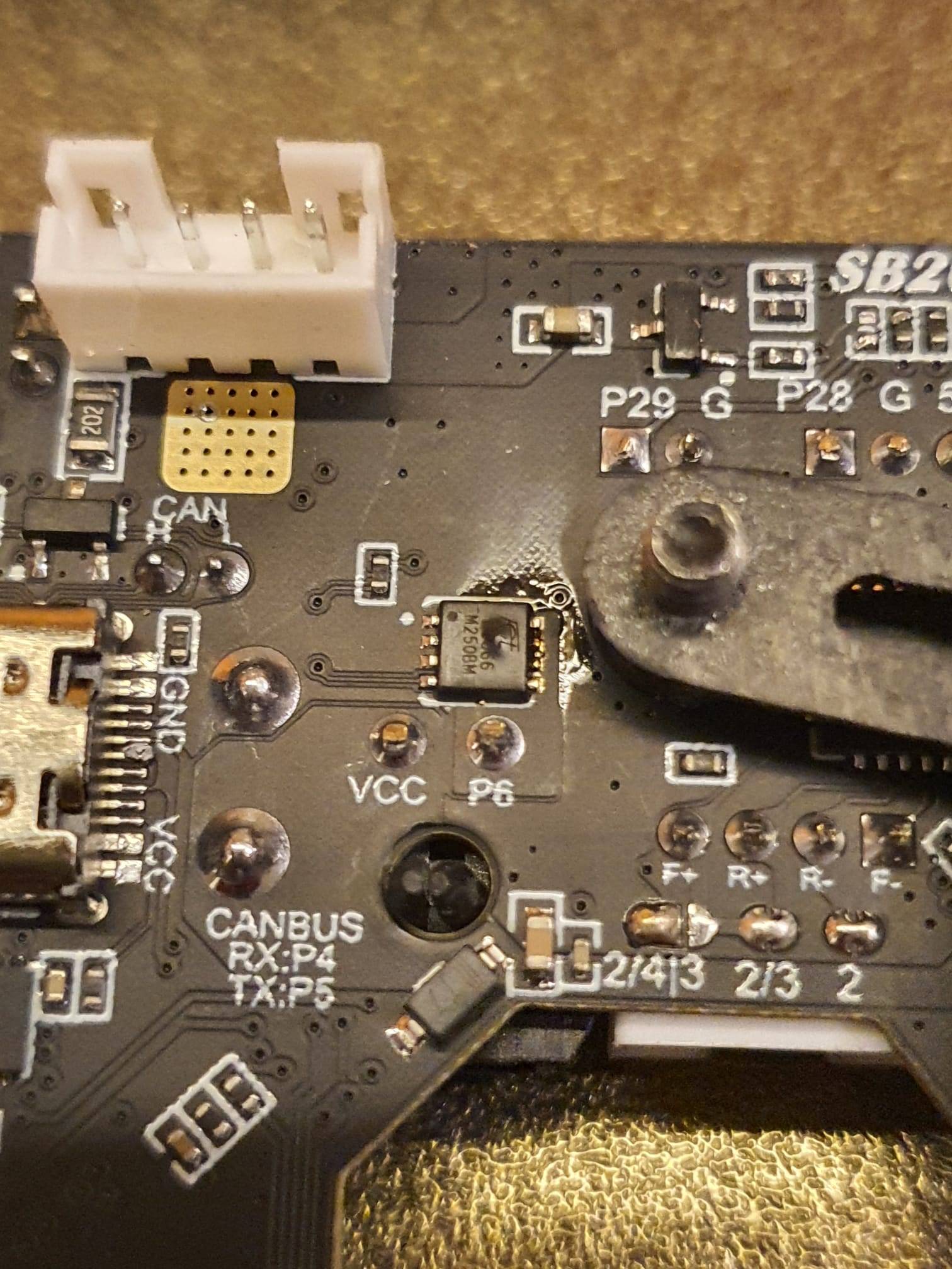
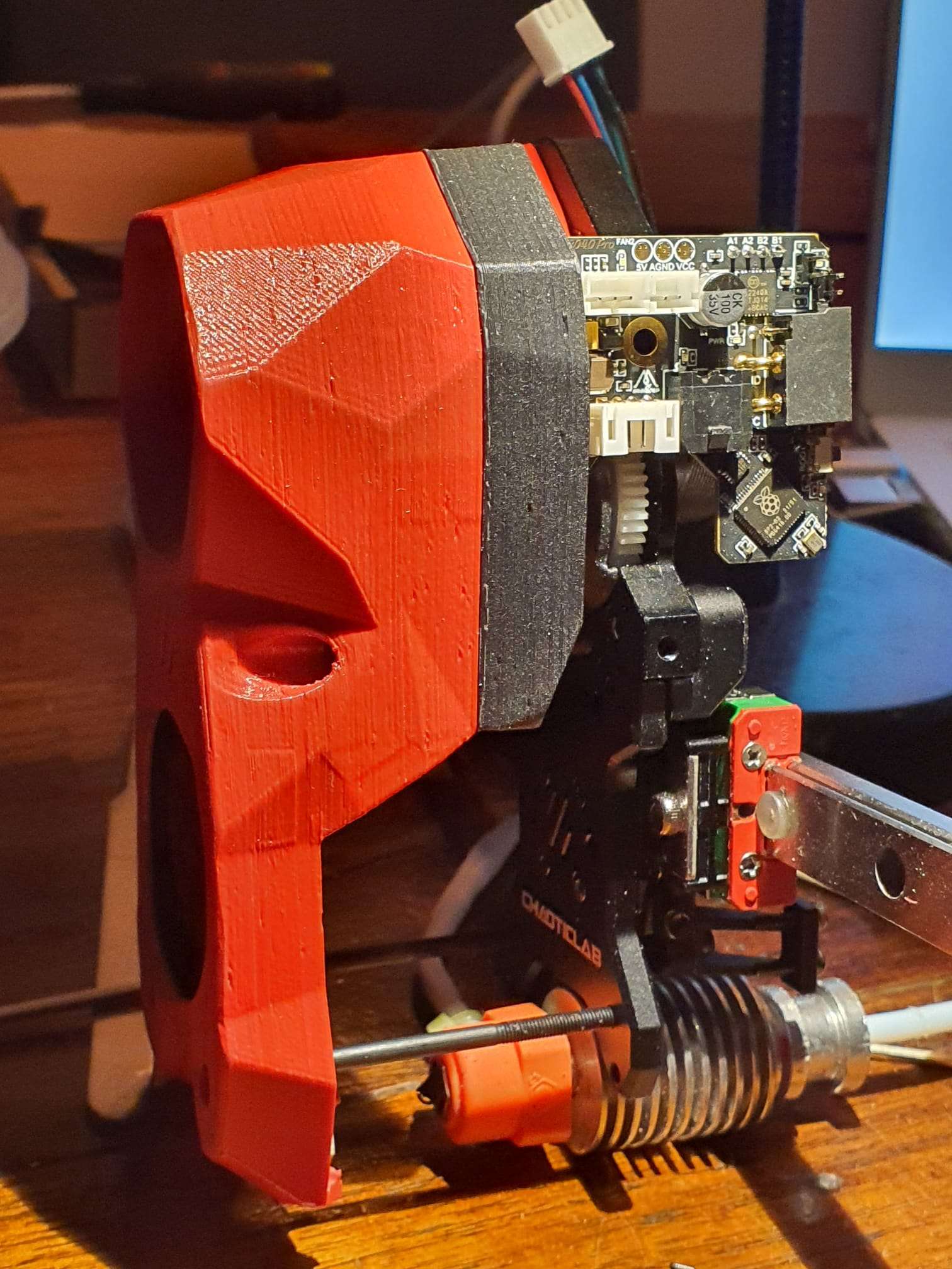
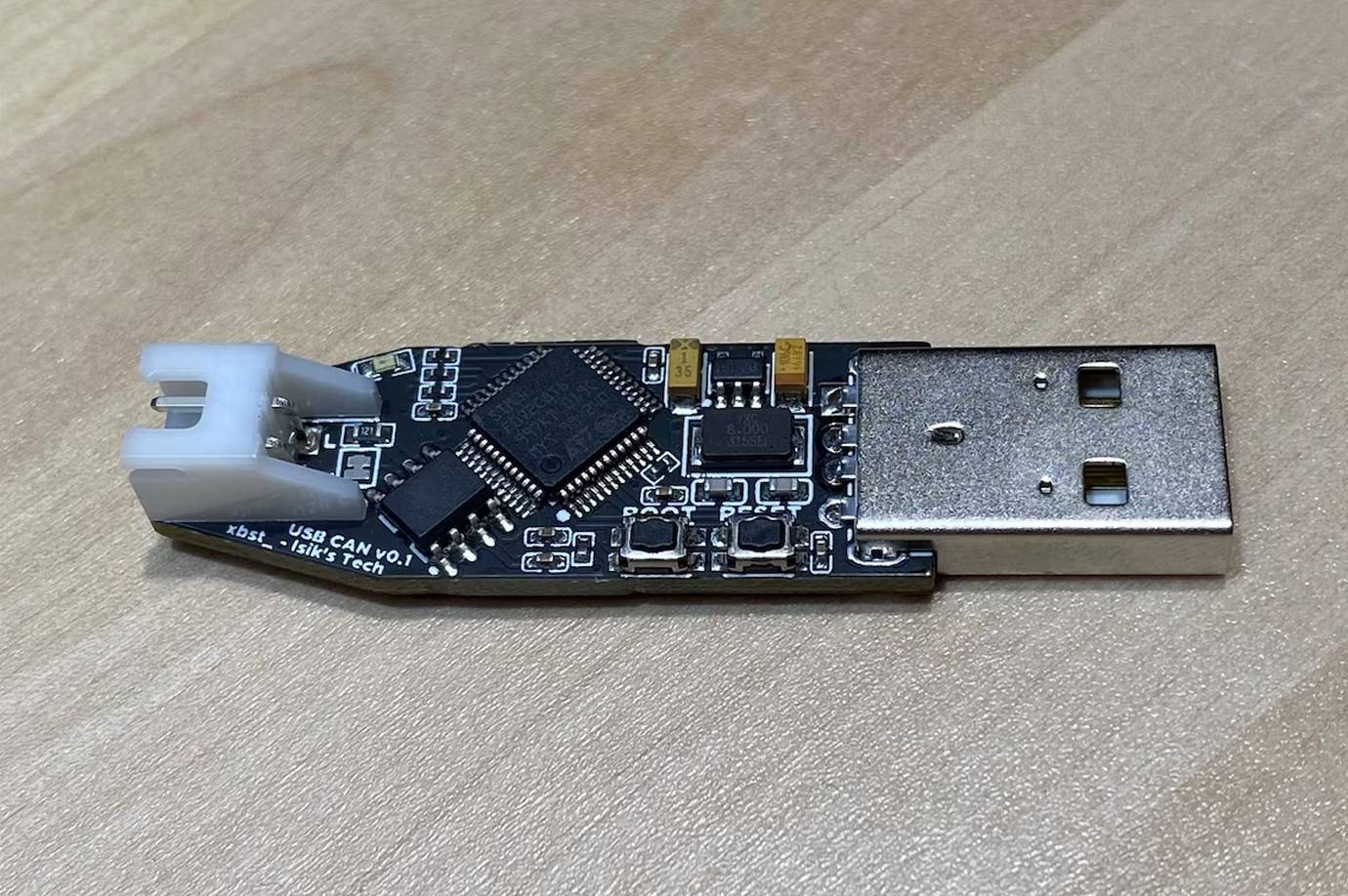
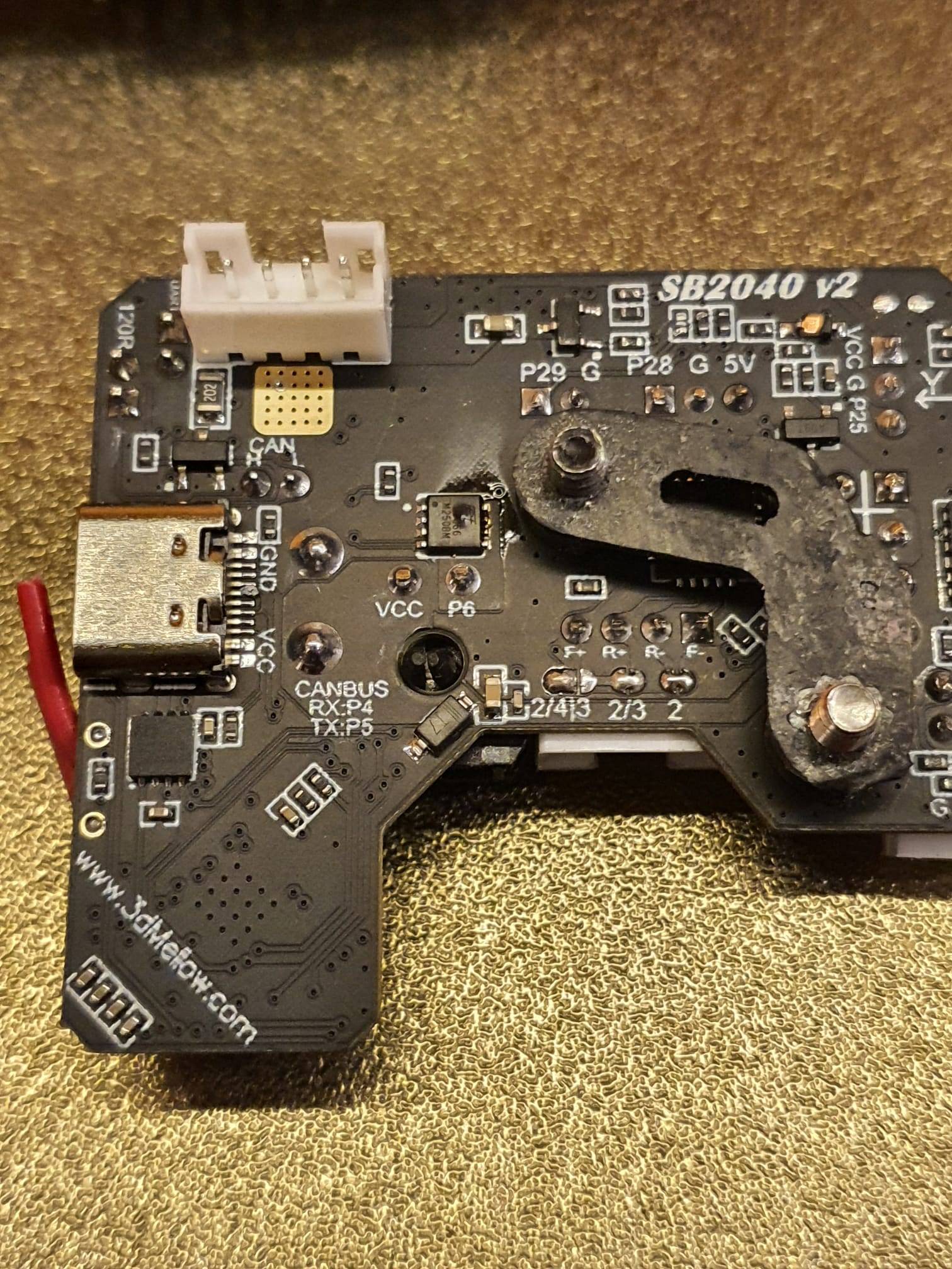
Due to my careless behaviour I damaged the hotend’s heater Mosfet of my Voron 2.4’s Stealthburner toolhead’s PCB.
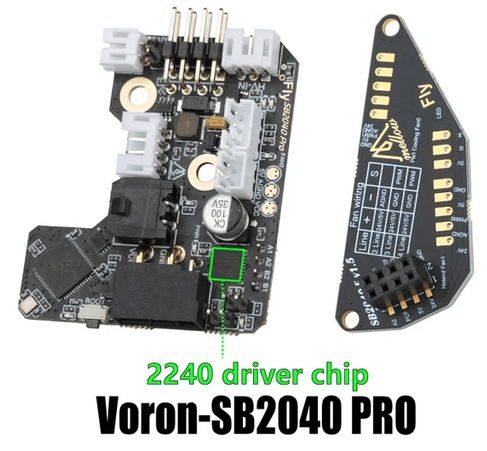
This toolhead PCB is a Mellow Fly SB2040 Pro plus. It has an accelerometer, a 2240 TMC, and it works with PT100 for the heater. It works very well through Canbus and my installed PICAN USB-interface on the RPI.
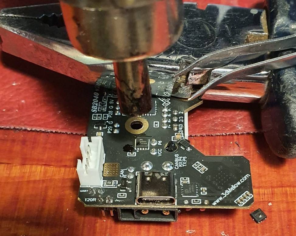
But- when I was installing another nozzle in the hotend, I shorted the ceramic heater cartidge and blew the heater Mosfet. See the next picture:
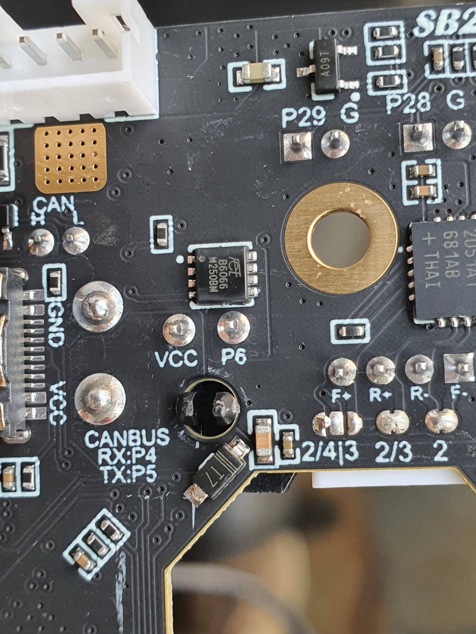
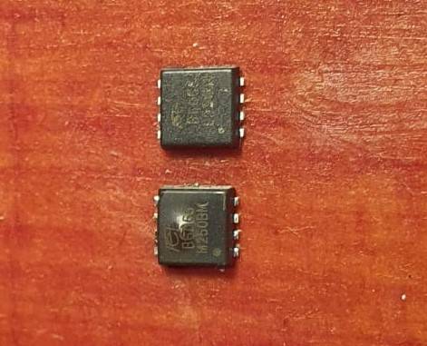
I ordered a new toolhead board and now I could tell the part number:
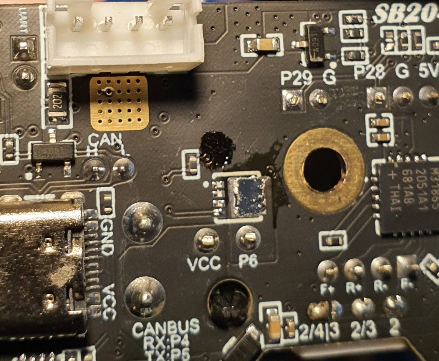
I ended up ordering 5 pieces of replacement B6066 Mosfet modules on Ali, and they were delivered yesterday, within 2 weeks.
I desoldered the defective one with my SMD heatgun, and ut a new one in with that same heatgun, works very well!!
So- what do you think is wrong with this ABS printed testcube after my switch from a standard 0.5 mm nozzle to an 0.6mm Chinese CHT high-flow nozzle?
I did not change anything other than the Curaslicer settings from 0.5mm to 0.6mm and also in Klipper, in the printer.cfg I also changed the setting from 0.5 to 0.6mm nozzle diameter.
Obviously, I also resliced the gcode before printing the testcubes.
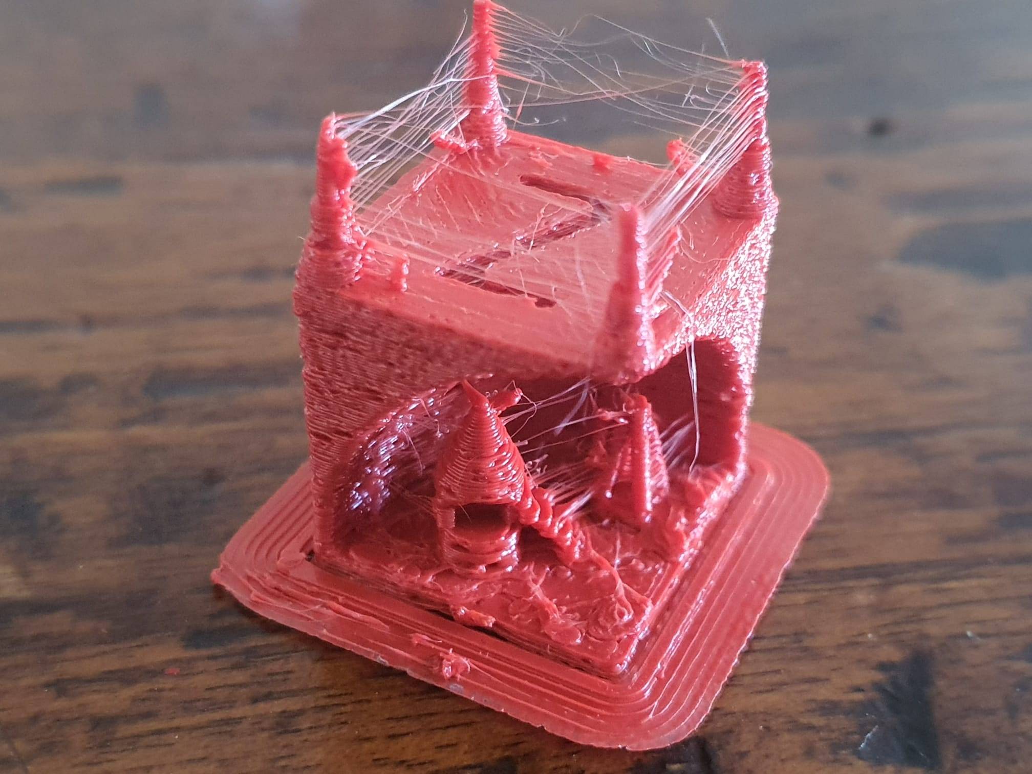
It has been printed on my Voron 2.4R1- 300. with a nozzle as shown in the below picture:
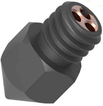
These specific nozzles should be able to produce more flow since the input channel consists out of 3- instead of 1- little hole. The tip is – of course- only 1 hole.
After the failed print, I did the following:
Changed the ABS filament for a fresh pack. No change.
I checked the retraction settings in Curaslicer which were just fine, between 0.5 and 1mm.
Tested the gcode on my big Voron which also has an 0.6 nozzle and this worked just fine.
So- I checked the input of the filament for drag and it went very difficult. Apparantly something causes drag in the way from the enclosed filament box to the extruder.
Exchanged the filament sensor because it caused quite some drag and this made some difference in the printed result but not that much.
Checked the extruder and recalibrated this, no change needed. 50 mm extrusion was indeed exactly 50mm filament going in.
All seemed OK but I still got the same blobby outside on the printed testcube.
So- finally I unscrewed the nozzle and- guess what: It is an 0.8 mm nozzle which came in the same small plastic bag along with all of my ordered 0.6 mm nozzles. Should have checked this beforehand, obviously!
Put a new Chinese CHT 0.6 mm nozzle in from the bag and now ALL IS ALMOST WELL! at least- a lot better.. AND the prints are pretty well usable,
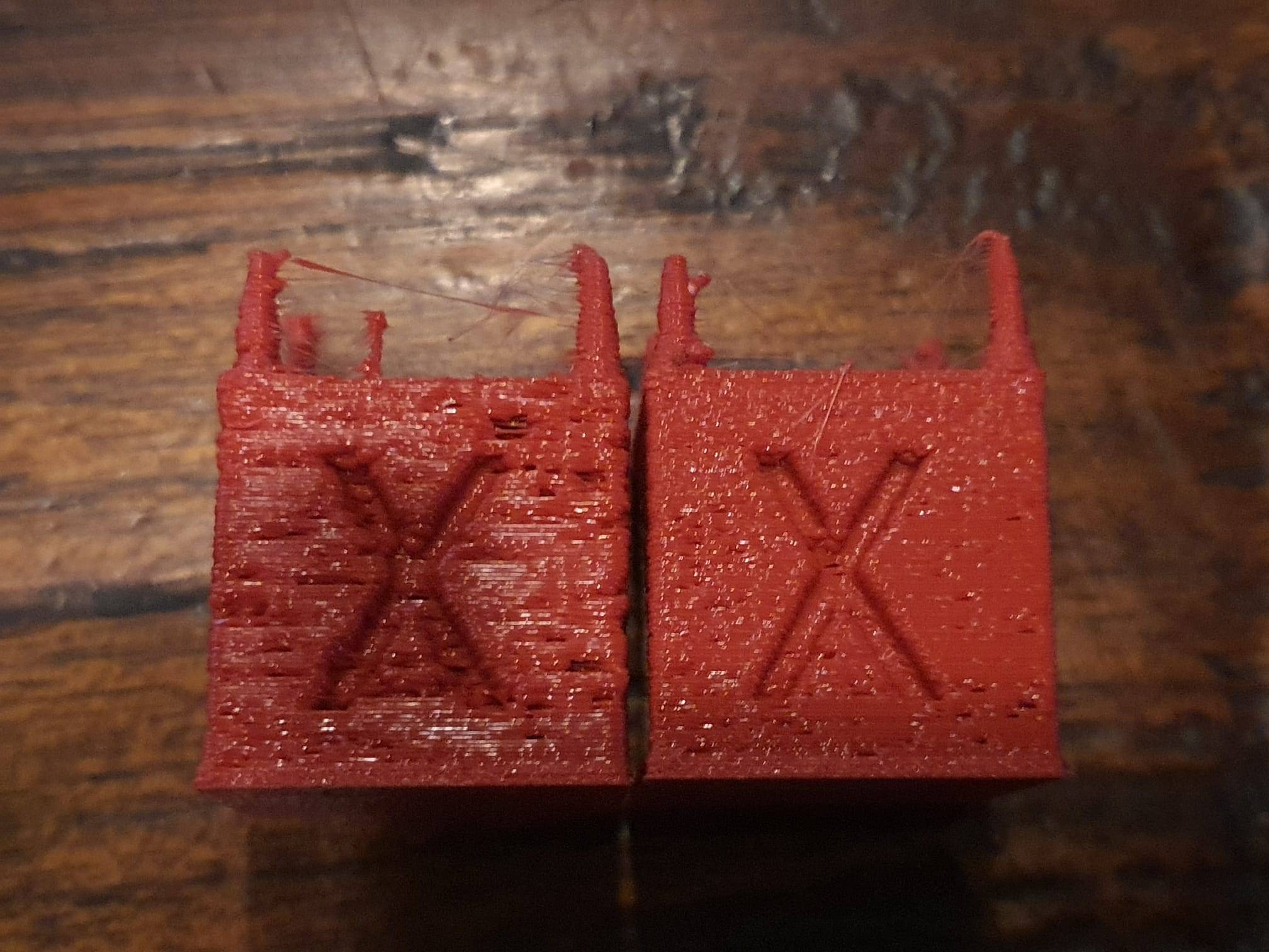
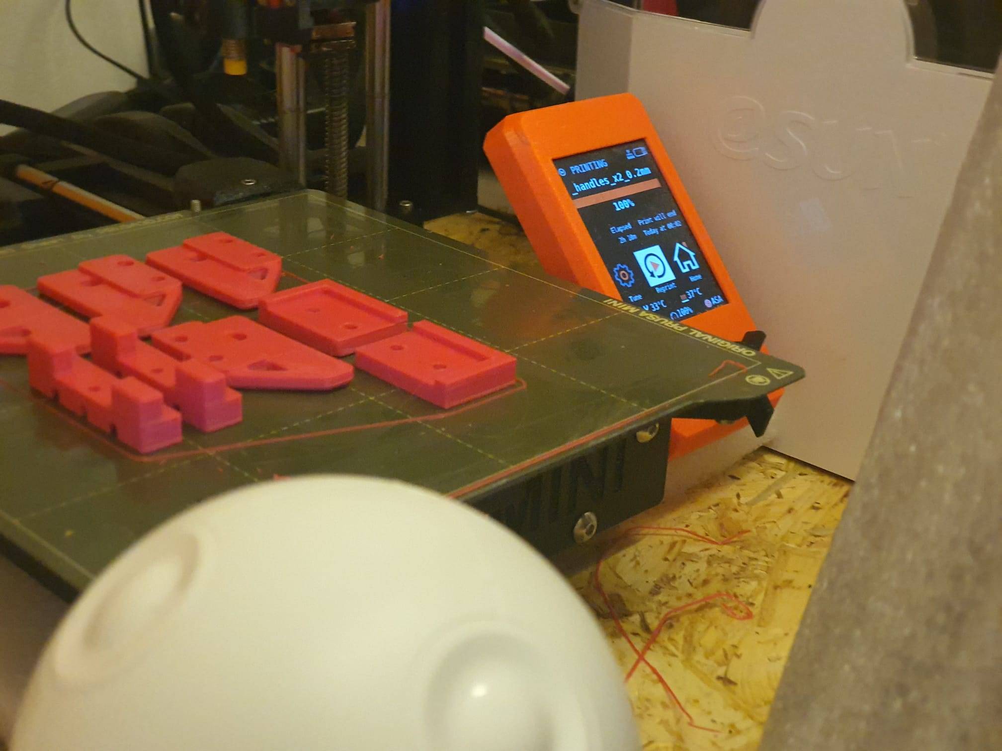
Both pictures: Voron 2.4 printing ABS at 280 degrees, Cura and Klipper setting for an 0.6mm nozzle. Left has an 0.8mm nozzle mounted, on the right is an 0.6mm nozzle mounted, Both nozzles are the high-flow ‘CHT’ Chinese nozzle versions with 3 internal flow channels.I quickly printed a couple of red ABS parts that I need for my big Voron 2.4R2-600.
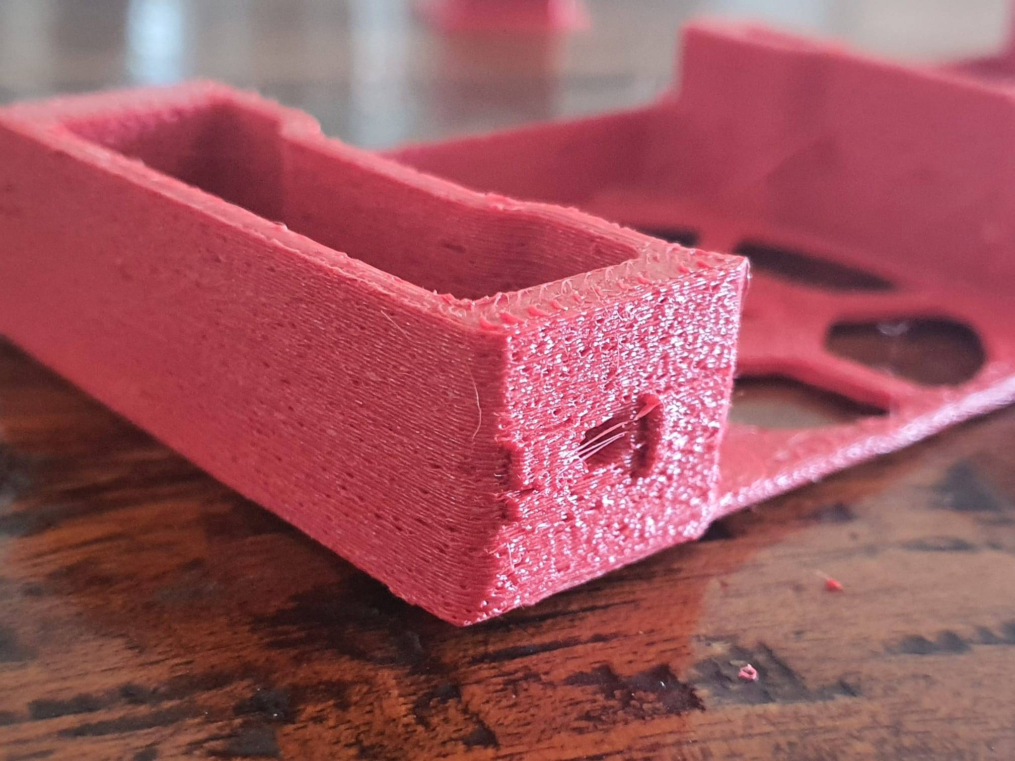
I am still working on the blobby surface, as is shown in the above picture, the right positioned testcube. Will try with some other filament! It is not the fuzzy skin option, by the way. It might be related to the high temperature that I use with this particular ABS filament, depending on the application I go up to 280 degrees. Best to try this first with PLA on 180-190 degrees, I guess.
Just got a so-called bright idea- Could it just be that I always had the temp for my extuder way too high and that such a high temp due to the better nozzle with more flow- is no longer required?
That might explain why the prints are now perfect and shiny- But the X an Y walls are somewhat blurry.
That might be due to the high setting for the extruder ‘s temperature.
I could also try to set the print fan on, or at least higher than my usual 25% for ABS.
Then I can see what the impact is, or just lower the extruder temp from 285 to 250 for my red ABS. Give it a shot. Will let you know!
BTW, I never ever had printed this ABS with a shiny XY surface. It was always matte, also at 285 degrees. Possibly the standard nozzle just required a higher temparature setting? I have actually never heard of something like this, we’ll see.
The following 2 pictures show what the printresult was when I printed at 240 degrees, 0.6mm nozzle and all of the rest was unchanged…
The walls printed pretty nice, only the top is not what I want. I will dig into that later.
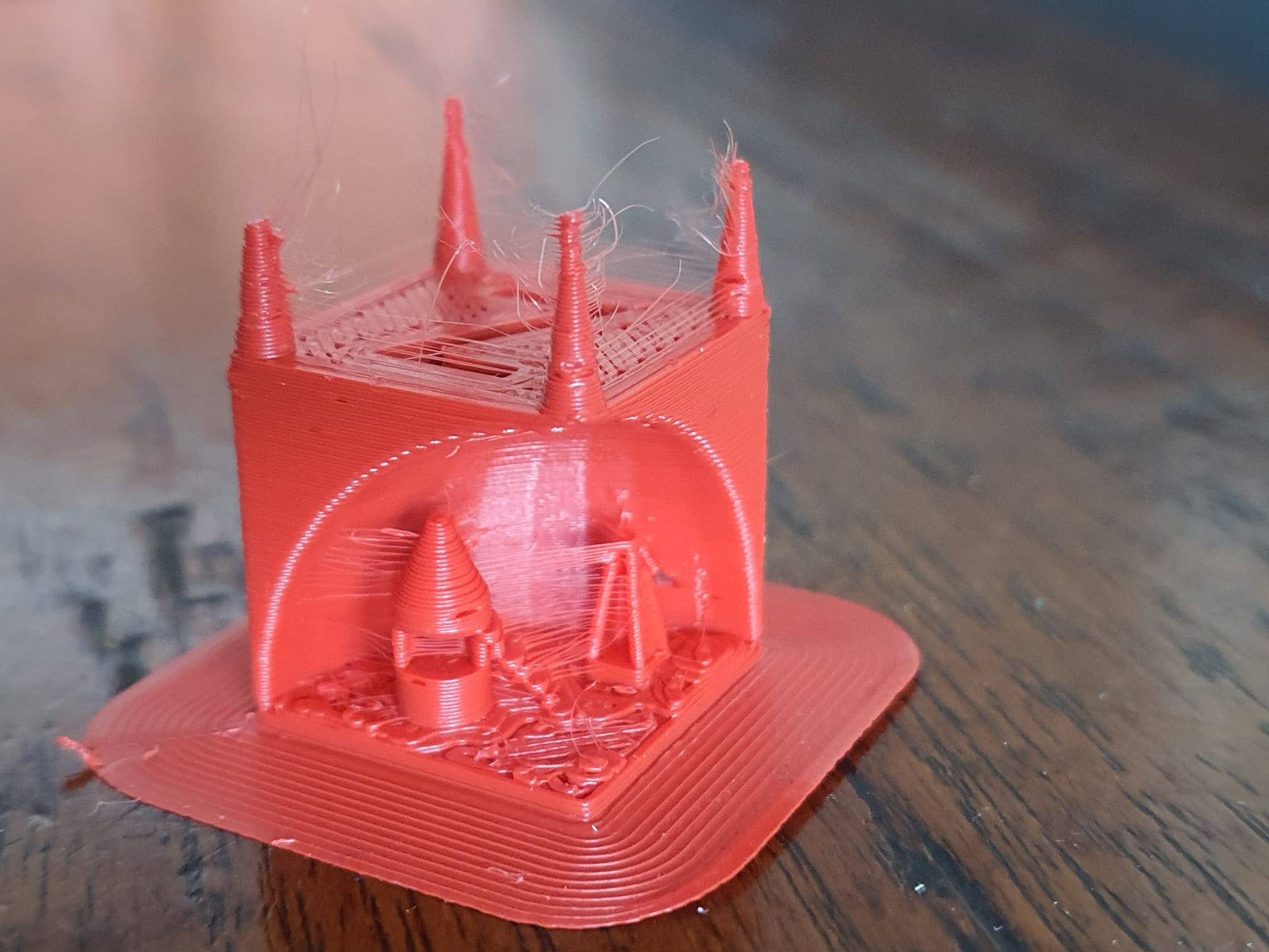
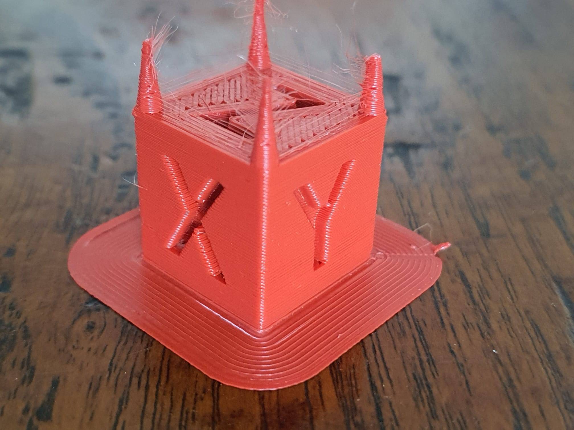
The sudden stringing when using the high-flow nozzle is obviously one clear indication that I am searching in the right direction for solving my fuzzy walls now. Previously, I never had stringing with the red ABS filament. The stringing was also a lot less when printing this ABS testcube at 240 degrees instead of 285 deg.
I will do a last test with the option to smooth the Z-surface better, will show this here as well! Could also be that the wall width for the top surface is set wrong, we’ll see. Or the temp for final printing too low, or the part-fan a bit too much at 30%?
To mount my Voren 2.4 R2 600x600mm heated bed solidly on the 3 pieces of 2020 aluminium rails, I used an alternative way, instead of the ,ethod that is usually done.
The reason is that I am using TAP as Z-probe and I want the bed to be mounted as sturdy as possible.
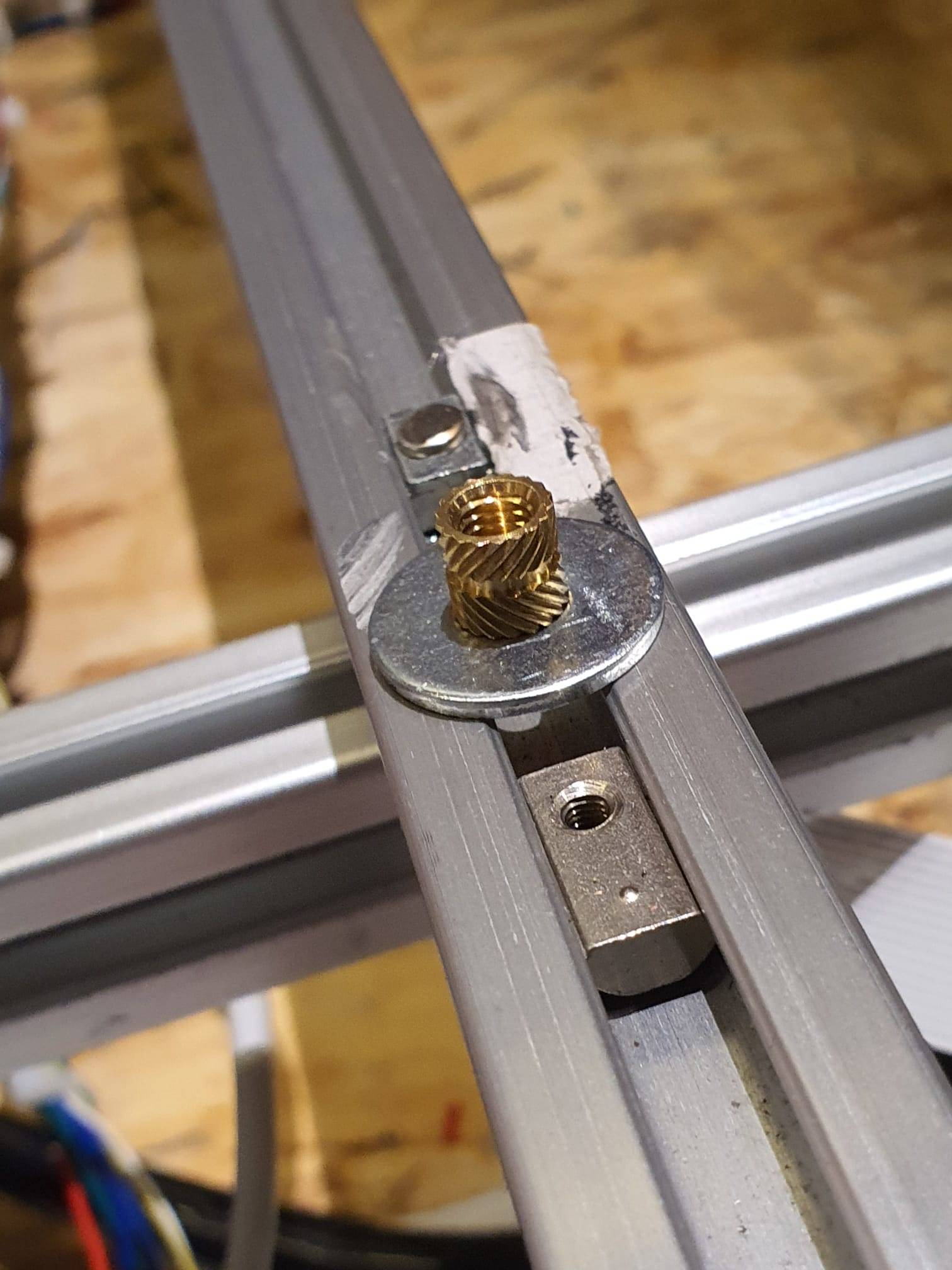
To do this, I used M3 nuts in the rails under the heated bed, then a M6 washer and a copper M5 round threaded insert in which the M3 bolt can be mounted.
But- first I placed the heated bed on the 2020 rails and made small marks where the M3 nut needs to be placed EXACTLY! Then, take the heated bed off and proceed.
The M5 threaded insert has a small cutaway ledge that just fits in the M6 washer, as is shown below:
This keeps the M5 copper threaded insert in place in the M6 washer.
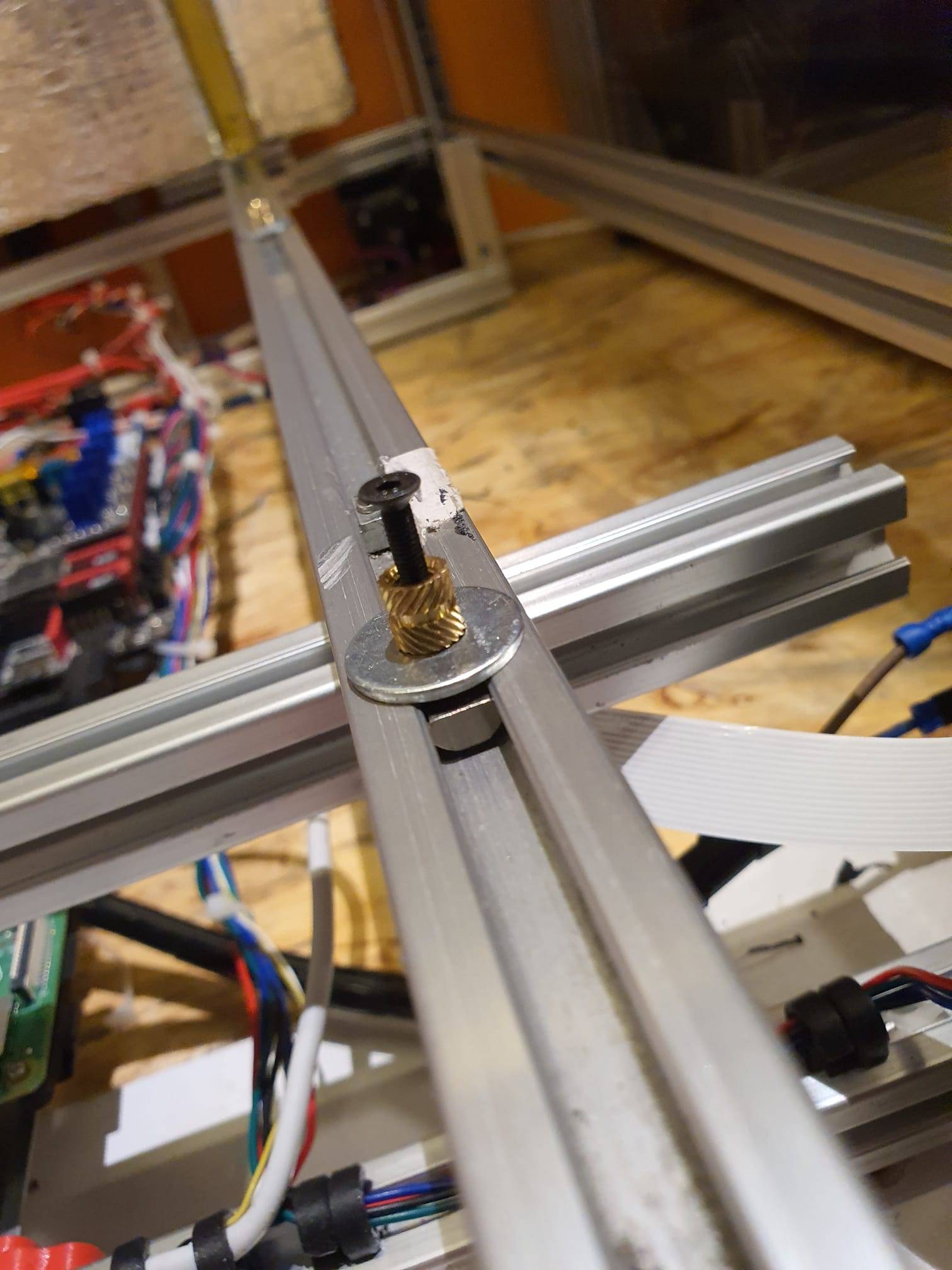
Then, the M3 16mm long bolt threads in the nut that is placed in the 2020 aluminium rail.
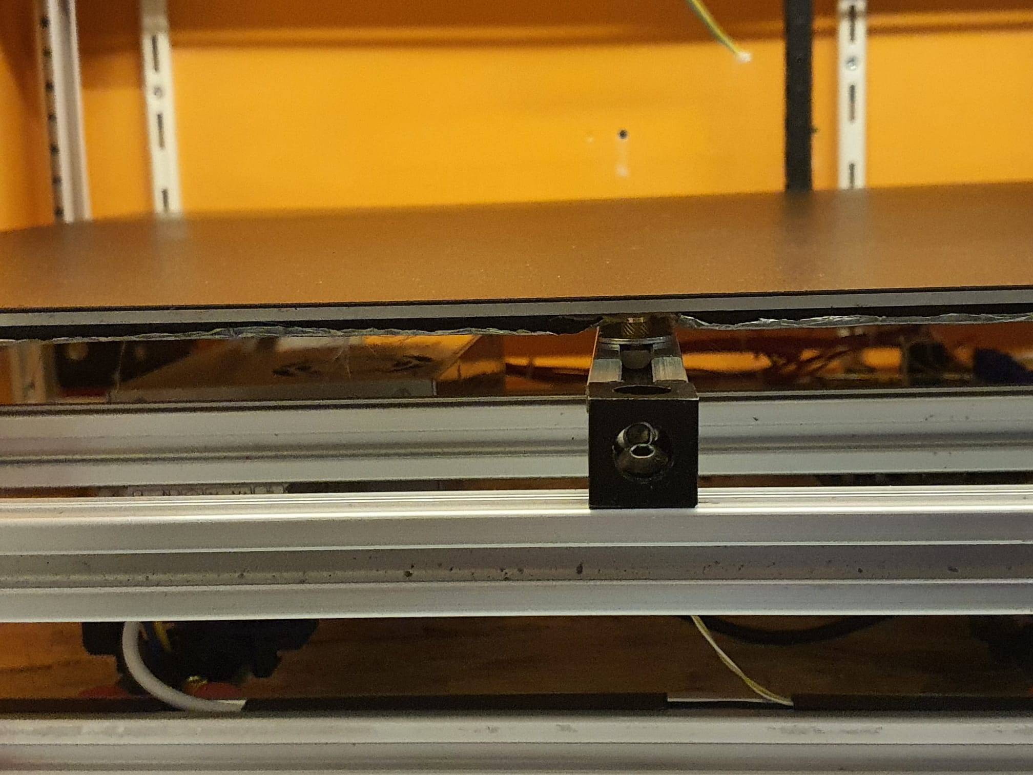
After all these have been fitted, remove the M3 bolts, place the heated bed on the threaded inserts and put the M3 bolts loosely in, thread one by one a bit in, place all af the M3 bolts.
Position the heated bed square in the frame and tighten the M3 bolts. You’re done!
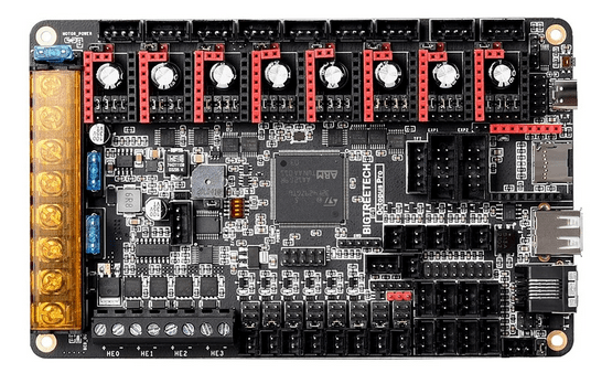
Before building my 600x600x500 (XYZ) Voron 2.4 3d printer, I decided which electronics I would use.
The choice for the electronics’ hard- and firmware was the following:
The Controller software is made as follows:
cd ~
git clone https://github.com/julianschill/klipper-led_effect.git
cd klipper-led_effect
./install-led_effect.shNB: Instead of octoprint, you can also use Fluidd or Mainsail
The firmware and configs of this build is described HERE
For a specific printjob, I really need a large 3d printer.
The largest printsize I had before building this big Voron 2.4R2 printer is my 330x330x400mm A30M.
But that only does PLA since it does not have an enclosure and the bed is not capable of anything over 70 deg C.
After a lot of searching I decided to build a new Voron 2.4 3d printer, sized 600 x 600 x 480 mm. the main reason for this build is that I really like to build someting instead of buying something that I will want to change afterwards anyway.
The external size of the printer for this build is 760x760x750 which just fits my available space.
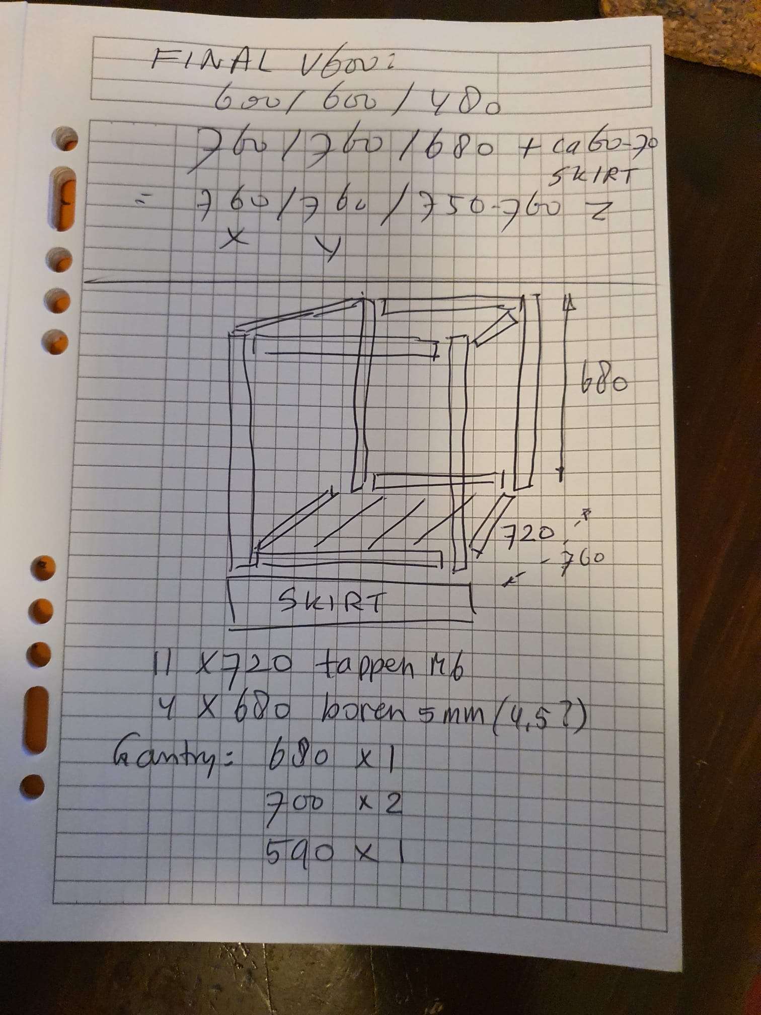
Since the door-opening (width) of my printing shop is only 700 mm, I can’t build the Voron 2.4 any larger than this, at least not at one of the sides. I do want the printer to be able to get out of the room when needed. I chose to keep the height of the externals within 700 mm. This means that the maximum Z-printing height will be ‘only’ 480 mm. If the printer ever needs to go outside, the top hat will be removed and it needs to be tilted 90 degrees before getting it out. But that’s fine, I don’t think the printer will be leaving very soon.
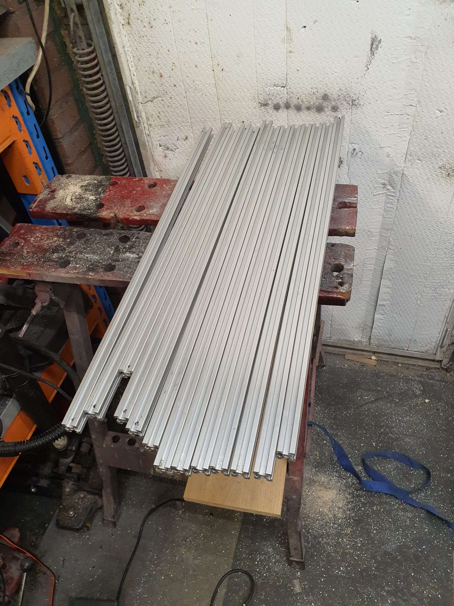
The build is continuing pretty fast. All electronics and printed parts are available. The 2020 extrusions were delivered yesterday, so next week I will cut, drill and thread the extrusions and will start building the frame.
I evaluated to make a different decision for the build, though, on the Z-height versus the width OR depth of the build. I need only one side to be within 700mm and this might be the depth of the build. If I would choose to do this, the printable volume would then be 600mm width x 540mm depth x 600mm height. That seems a lot better than 600x600x480. BUT- In my experience of printing BIG parts, I never reached the top of my large printers, only ever needed the X and Y to be as large as possible. Make any sense? In the end, I therefore stuck to the lesser Z-height since this will also fit well in my printer shop, because the shelves difference in height makes the printer fit well, also if I want a top hat like in the picture below, on my old Voron 300.
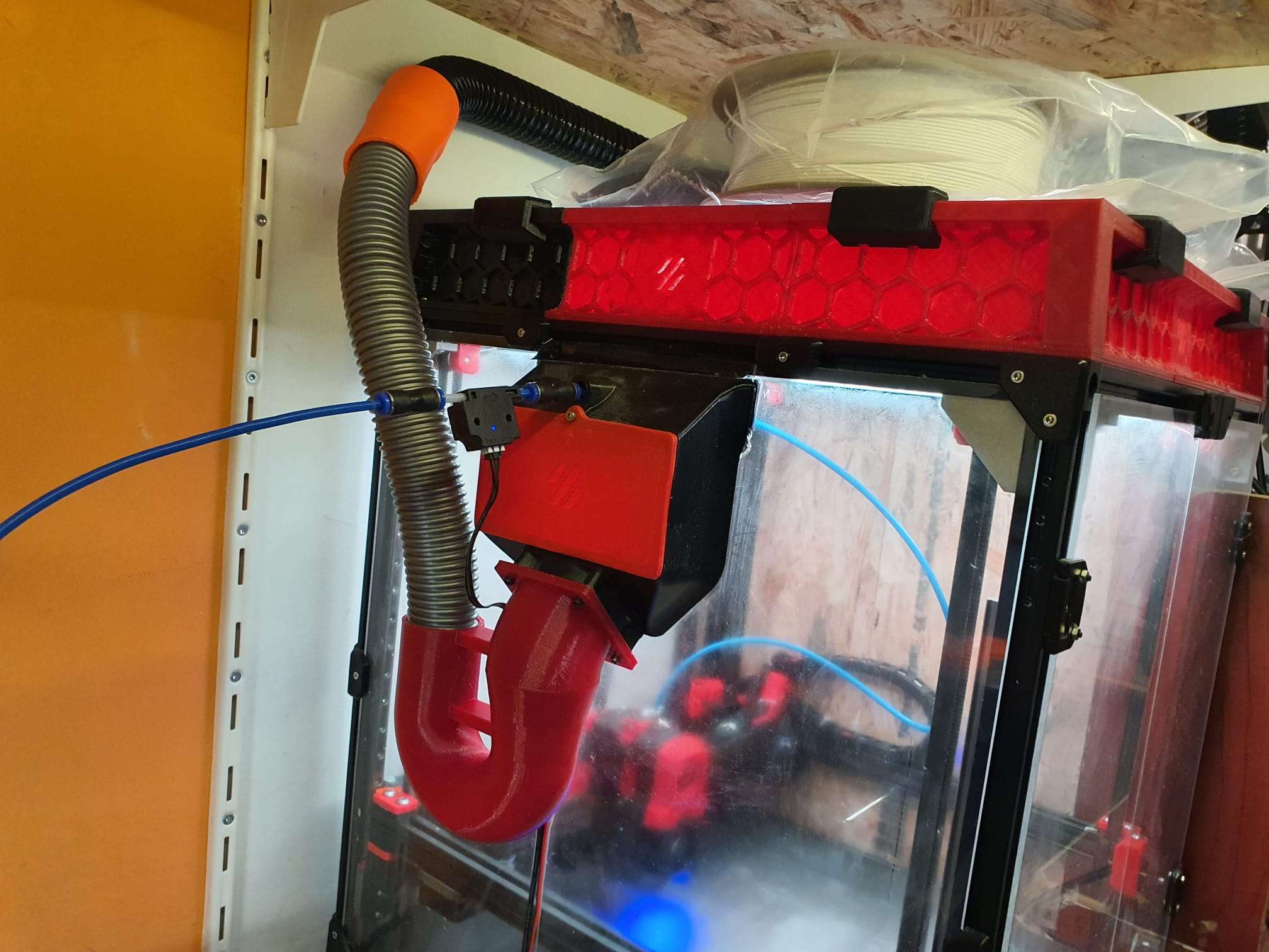

As shown in the above pictures, I also installed chaotic lab’s CNC-machined TAP module with the OMRON sensor. Since I will be using a bed with an X-Y of 600×600 mm, I expect that I will need a very good Z-sensor like hopefully the TAP will prove to be.
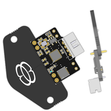
Alternatively, for a faster and more secure bed mesh I might want to put the IDM sensor in, at a later stage:
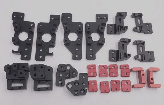
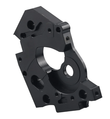
I first printed the extruder parts and all of the movement parts. I already had some leftover parts for the Z-axes from an earlier build. For the gantry, I bought a complete kit of CNC machined aluminum parts.
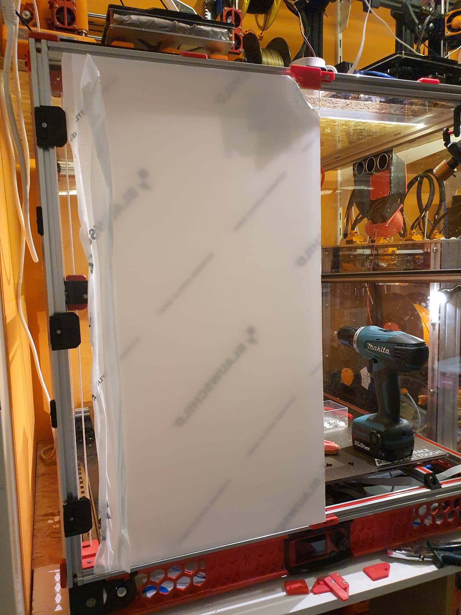
For the time being, I will make the outside covers from thin triplex wood. Only after all is well and I know the printer works perfect, i will decide how to move on. My earlier model Voron 2-300 has all transparant acrylic covers and that is nice but always dirty from fumes. I might go with aluminum dibond on all sides but the front. If I will use dibond, I will screw it directly on the 2020 profiles to get as much rigidity as possible.
I ordered and received a Tronxy 24 Volts 500 Watts 600×600 heated bed as is used in Tronxy’s large volume HEVO printer. Thanx guys!
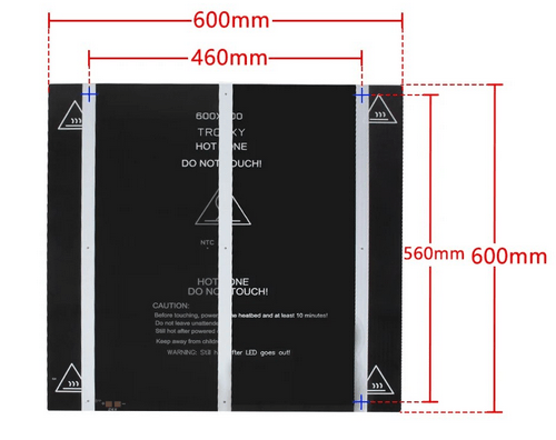
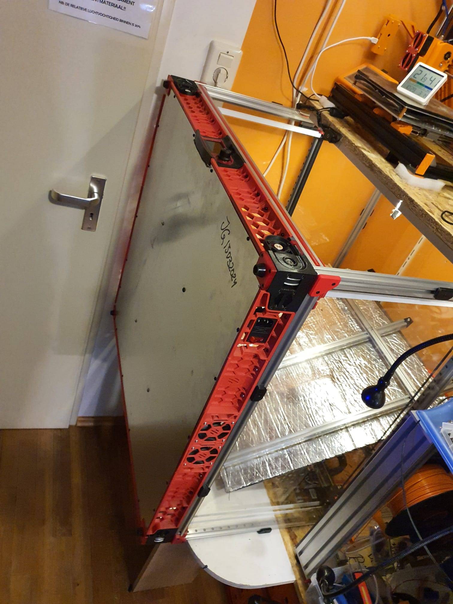
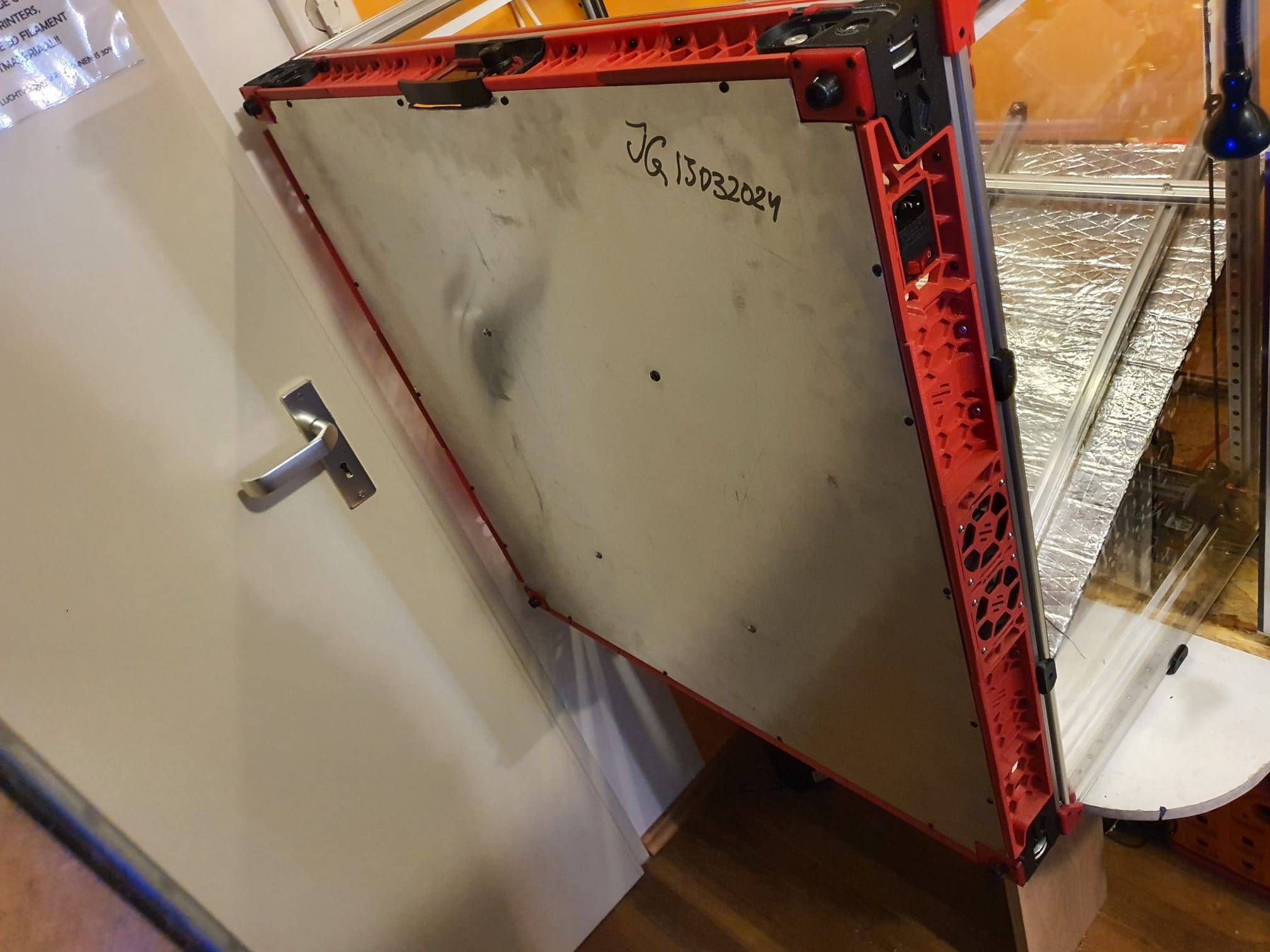
In this build, I will use 3 extrusion 2020 parts to mount this large bed in the Voron’s frame. I intend to fit the bed including extrusions tiltable, hinged at the rear. In my view, there is no way I will ever reverse the printer once it is in place in my printer shop. To reach the electronics, making a tilting bed is really the only solution.
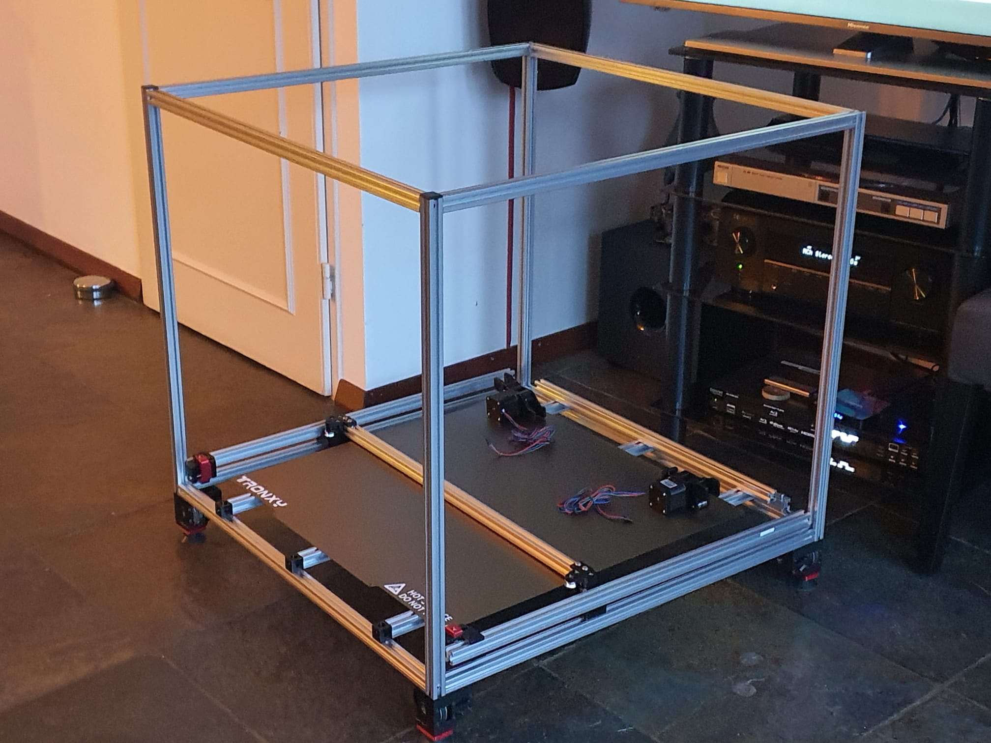
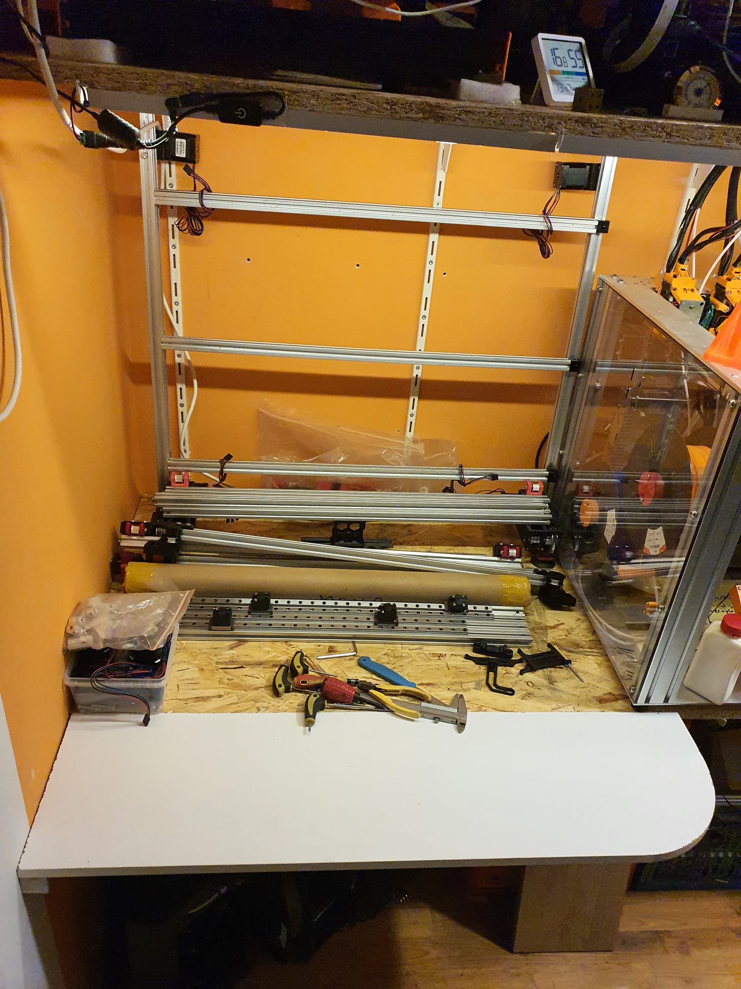
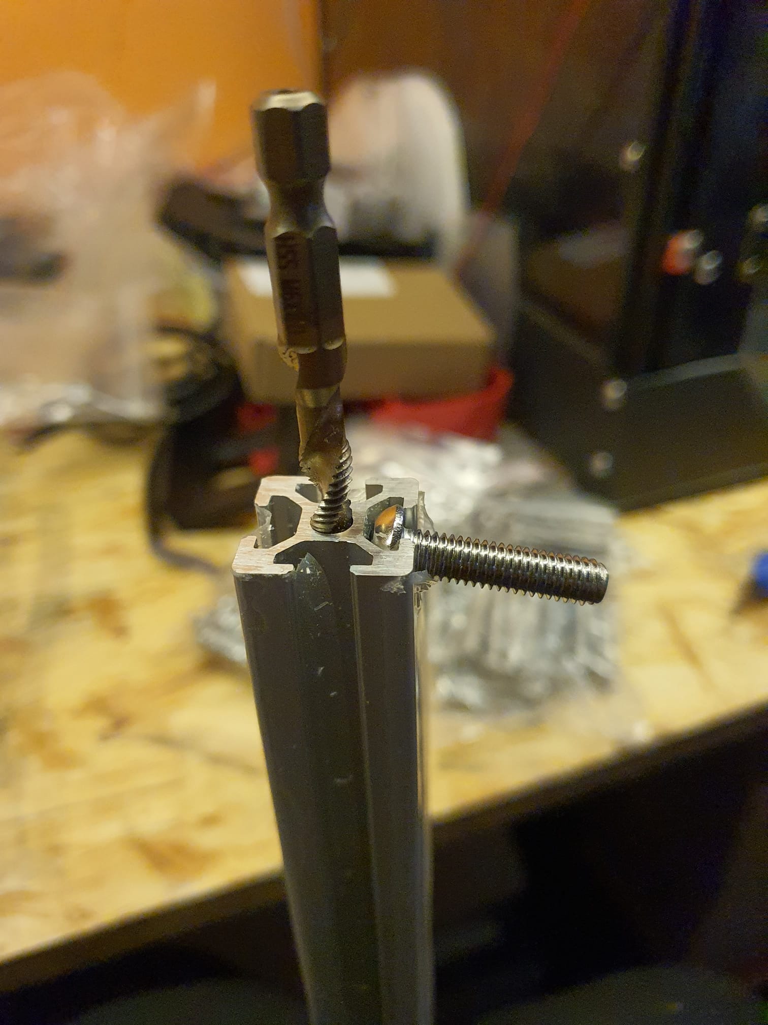
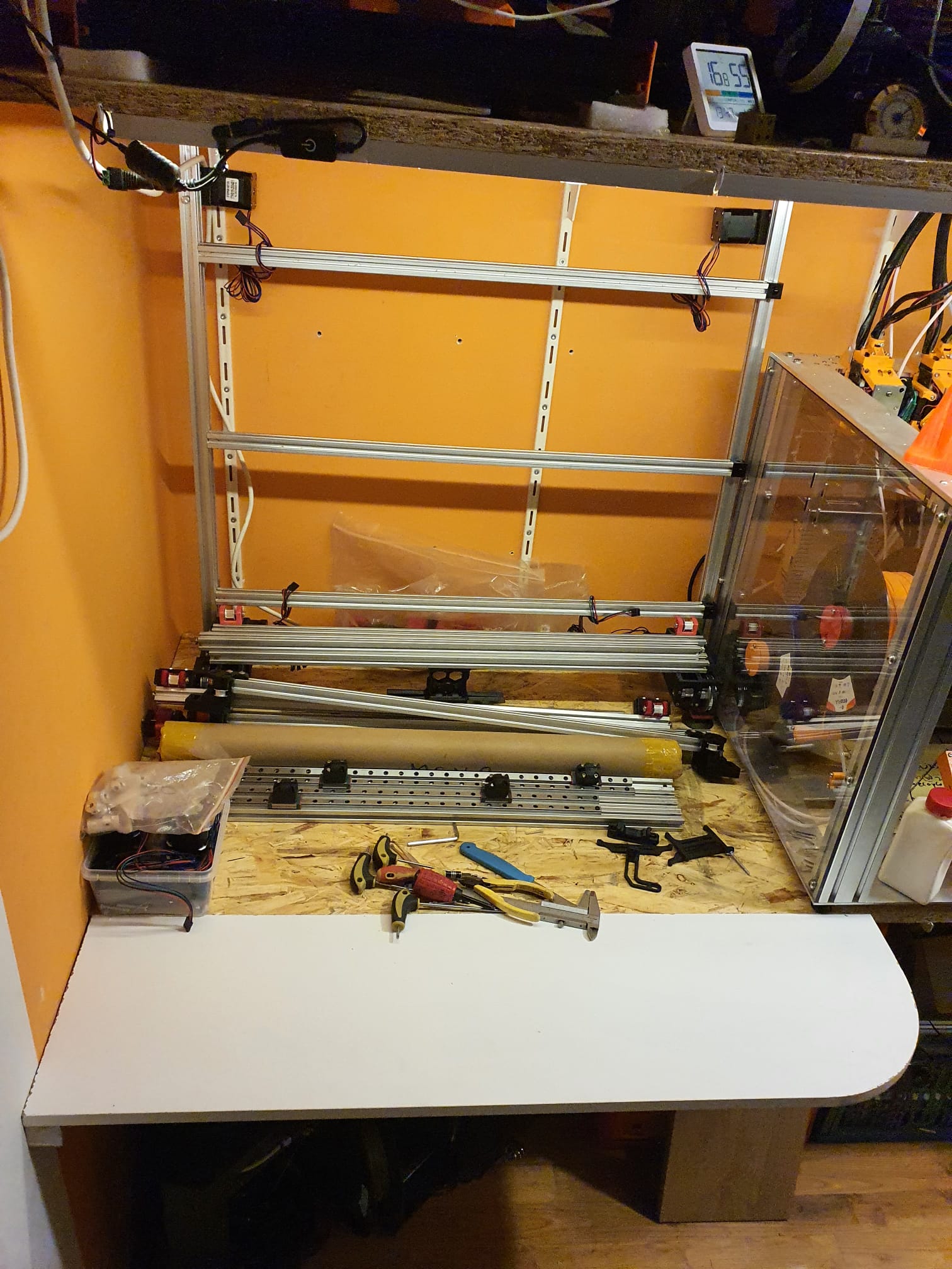
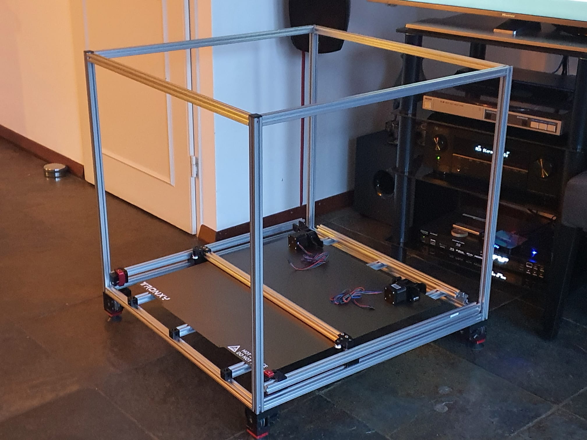
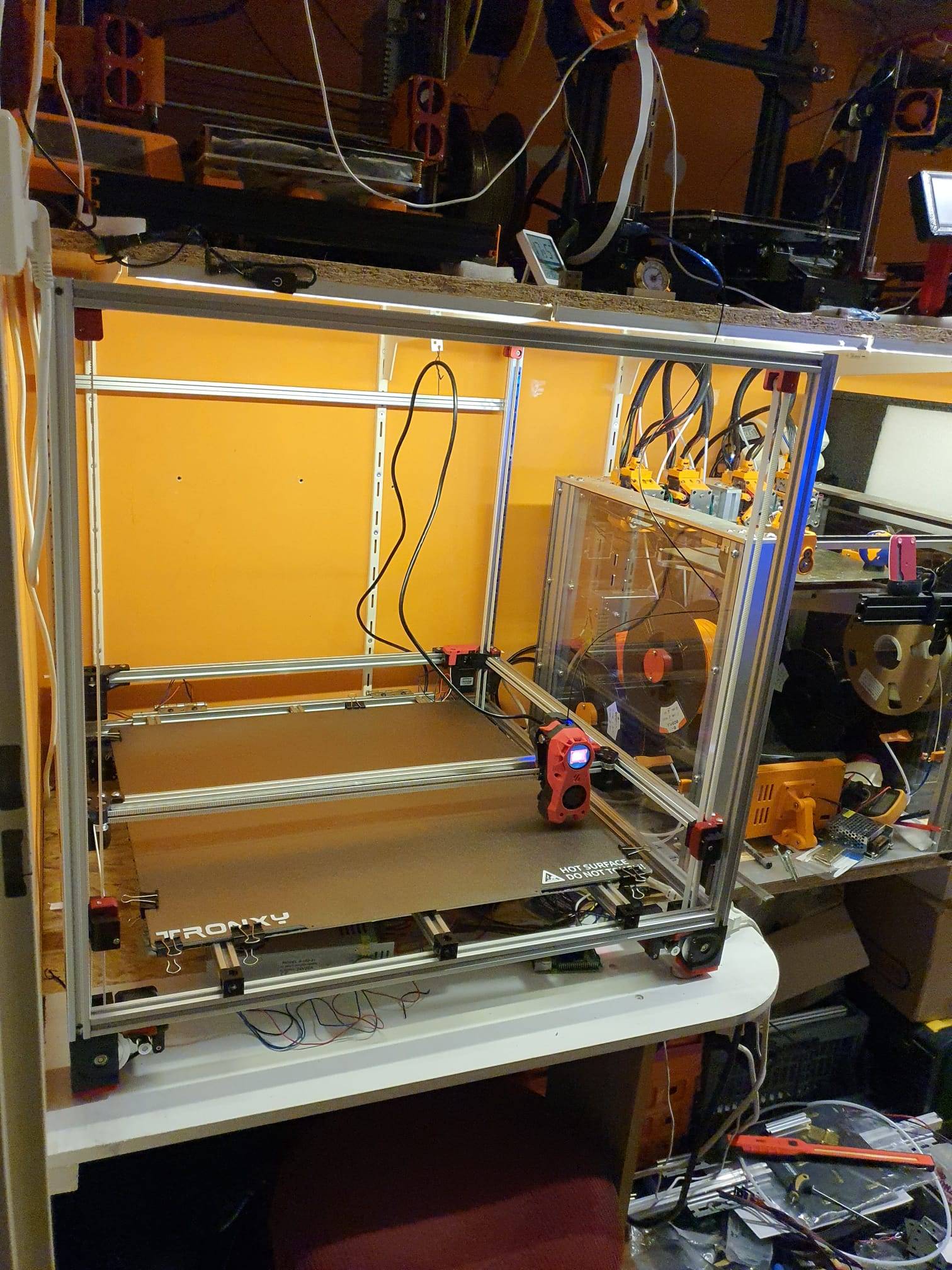
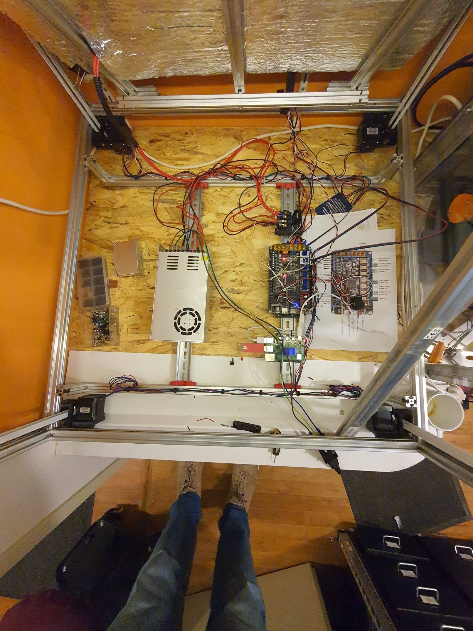
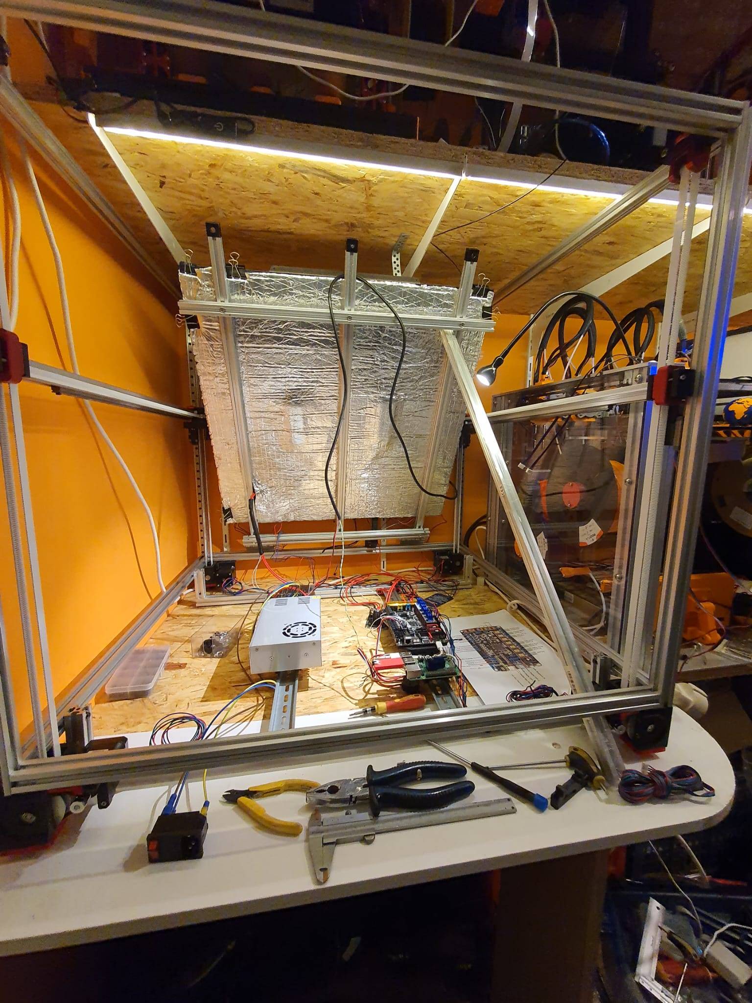
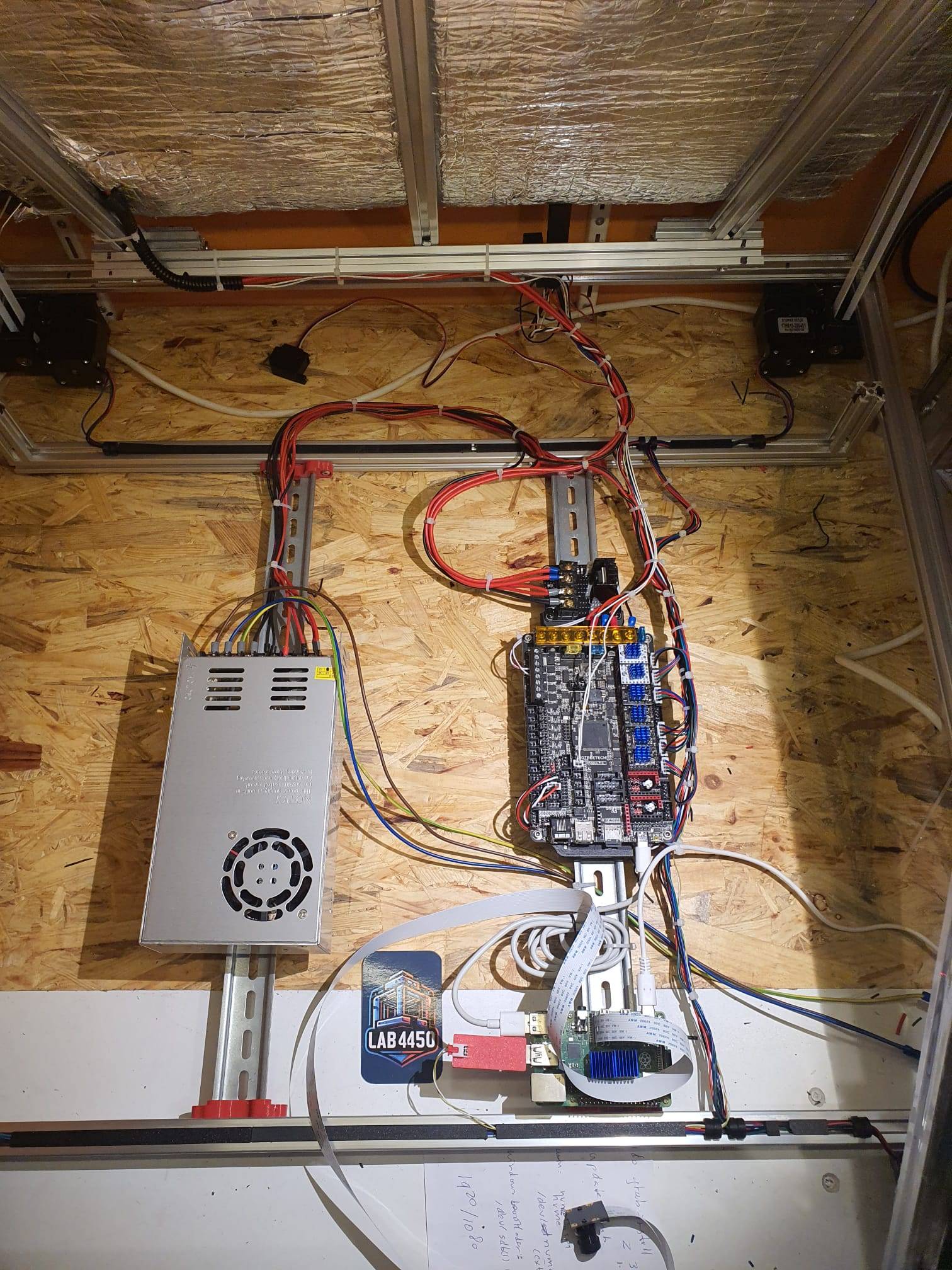
The above concludes the build of the hardware.
The repair of the Hotend Canbus module, the build of the enclosure and so on will all be added as additional posts.
The firmware and configs is described in another post HERE
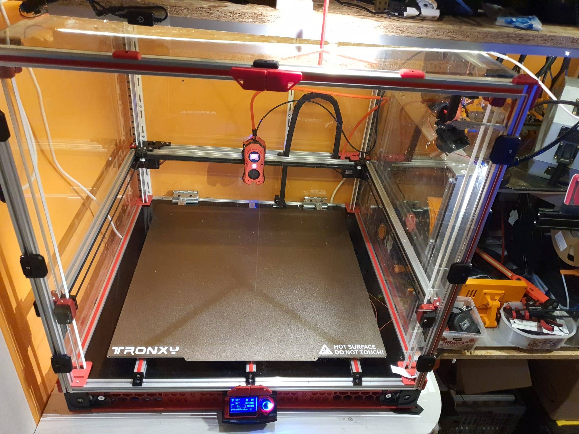
 Video van WhatsApp op 2024-03-16 om 14.34.15_29d2041d Video van WhatsApp op 2024-03-16 om 14.33.45_8bd30d74
An upgrade to Python 3 is neccessary since Octoprint keeps mentioning at startup that future updates after 1.72 will no longer be supported when running a Python2 environment.
Since I made my Voron2.4 printer in 2018, this is still based on Python2.
I first followed the advice on the Octoprint website: Make a full backup from the RPI with the backup/restore plugin of Octoprint, save it to your local HDD.
Then, make a new image from Raspberry PI imager, selecting te most current Octopi image from the RPI imager’s menu. Then, burn it on a micro SD card, take SD out and in again, change the wifi settings to whatever you have at home. And, put it in your Raspberry PI. Put the power on and wait some minutes. Search for your RPI with either bonjour os just use angry IP Scanner and find the local IP address. Start PuTTY and login to the RPI with ‘pi’ username and ‘raspberry’ password. Type ‘ ‘ and Enter. In the menu: Change the RPI’s login password to the one you used before and save it. Logout of PuTTY.
Now, login to octoprint with your browser at the identified local IP address and restore the locally saved backup. This shoud take a long time to install. After this, reboot and it should all work again.
BUT- it did not work at all. Somehow either not all files are backupped and restored or I am missing some config settings. Octoprint could not connect to the SKR4 boards, hence the LCD display did not work and without communnication to the boards, nothing could be done. I tried to remedy the problem but after an hour or so I decided to go for a fresh re-install.
I did save the config file previously so with this and a fresh install I should be fine.
The rest of this post describes my search- and find- and is a HOW TO to help you do it right without any searching. Most of it is gathered from all these good sites where parts of the solution for ths specific configuration can be found and I just tied them together for the Voron2.4 with a Raspbery PI 4B and 4GB memory, with 2 x BTT SKR1.4T and a standard RGB LCD display connected with 2 block cabled wire connectors , the LCD also has a lit turning knob (see the pictures at the end of this post):
These instructions assume the software will run on a Raspberry Pi computer in conjunction with OctoPrint. It is recommended that a Raspberry Pi 2, 3, or 4 computer be used as the host machine (see the FAQ for other machines).
Klipper currently supports a number of Atmel ATmega based micro-controllers, ARM based micro-controllers, and Beaglebone PRU based printers.
Prepping an OS image
Start by installing OctoPi on the Raspberry Pi computer. Use OctoPi v0.17.0 or later – see the OctoPi releases for release information. One should verify that OctoPi boots and that the OctoPrint web server works. After connecting to the OctoPrint web page, follow the prompt to upgrade OctoPrint to v1.4.2 or later.
After installing OctoPi and upgrading OctoPrint, it will be necessary to ssh into the target machine to run a handful of system commands. If using a Linux or MacOS desktop, then the “ssh” software should already be installed on the desktop. There are free ssh clients available for other desktops (eg, PuTTY). Use the ssh utility to connect to the Raspberry Pi (ssh pi@octopi — password is “raspberry”) and run the following commands:
git clone https://github.com/Klipper3d/klipper
./klipper/scripts/install-octopi.sh
E: Repository ‘http://archive.raspberrypi.org/debian buster InRelease’ changed its ‘Suite’ value from ‘testing’ to ‘oldstable’
N: This must be accepted explicitly before updates for this repository can be applied. See apt-secure(8) manpage for details.
Omdat de repository veranderd is van “testing ” naar “stable” moet je eenmalig toestemming geven om deze verandering in de repository te accepteren. Dit doe je met het volgende commando,
sudo apt-get update –allow-releaseinfo-change
Hierna kan je gewoon weer updaten met,
sudo apt-get update
git clone https://github.com/Klipper3d/klipper
./klipper/scripts/install-octopi.sh
The above will download Klipper, install some system dependencies, setup Klipper to run at system startup, and start the Klipper host software. It will require an internet connection and it may take a few minutes to complete.
Building and flashing the micro-controller
To compile the micro-controller code, start by running these commands on the Raspberry Pi:
cd ~/klipper/
make menuconfig
Select the appropriate micro-controller and review any other options provided. Once configured, run:
make
It is necessary to determine the serial port connected to the micro-controller. For micro-controllers that connect via USB, run the following:
ls /dev/serial/by-id/*
It should report something similar to the following:
/dev/serial/by-id/usb-1a86_USB2.0-Serial-if00-port0
It’s common for each printer to have its own unique serial port name. This unique name will be used when flashing the micro-controller. It’s possible there may be multiple lines in the above output – if so, choose the line corresponding to the micro-controller (see the FAQ for more information).
For common micro-controllers, the code can be flashed with something similar to:
sudo service klipper stop
make flash FLASH_DEVICE=/dev/serial/by-id/usb-1a86_USB2.0-Serial-if00-port0
sudo service klipper start
Be sure to update the FLASH_DEVICE with the printer’s unique serial port name.
When flashing for the first time, make sure that OctoPrint is not connected directly to the printer (from the OctoPrint web page, under the “Connection” section, click “Disconnect”).
Configuring OctoPrint to use Klipper
The OctoPrint web server needs to be configured to communicate with the Klipper host software. Using a web browser, login to the OctoPrint web page and then configure the following items:
Navigate to the Settings tab (the wrench icon at the top of the page). Under “Serial Connection” in “Additional serial ports” add “/tmp/printer”. Then click “Save”.
Enter the Settings tab again and under “Serial Connection” change the “Serial Port” setting to “/tmp/printer”.
In the Settings tab, navigate to the “Behavior” sub-tab and select the “Cancel any ongoing prints but stay connected to the printer” option. Click “Save”.
From the main page, under the “Connection” section (at the top left of the page) make sure the “Serial Port” is set to “/tmp/printer” and click “Connect”. (If “/tmp/printer” is not an available selection then try reloading the page.)
Once connected, navigate to the “Terminal” tab and type “status” (without the quotes) into the command entry box and click “Send”. The terminal window will likely report there is an error opening the config file – that means OctoPrint is successfully communicating with Klipper. Proceed to the next section.
Configuring Klipper
The Klipper configuration is stored in a text file on the Raspberry Pi. Take a look at the example config files in the config directory. The Config Reference contains documentation on config parameters.
Arguably the easiest way to update the Klipper configuration file is to use a desktop editor that supports editing files over the “scp” and/or “sftp” protocols. There are freely available tools that support this (eg, Notepad++, WinSCP, and Cyberduck). Use one of the example config files as a starting point and save it as a file named “printer.cfg” in the home directory of the pi user (ie, /home/pi/printer.cfg).
Alternatively, one can also copy and edit the file directly on the Raspberry Pi via ssh – for example:
cp ~/klipper/config/example-cartesian.cfg ~/printer.cfg
nano ~/printer.cfg
Make sure to review and update each setting that is appropriate for the hardware.
It’s common for each printer to have its own unique name for the micro-controller. The name may change after flashing Klipper, so rerun the ls /dev/serial/by-id/* command and then update the config file with the unique name. For example, update the [mcu] section to look something similar to:
[mcu]
serial: /dev/serial/by-id/usb-1a86_USB2.0-Serial-if00-port0
After creating and editing the file it will be necessary to issue a “restart” command in the OctoPrint web terminal to load the config. A “status” command will report the printer is ready if the Klipper config file is successfully read and the micro-controller is successfully found and configured. It is not unusual to have configuration errors during the initial setup – update the printer config file and issue “restart” until “status” reports the printer is ready.
Klipper reports error messages via the OctoPrint terminal tab. The “status” command can be used to re-report error messages. The default Klipper startup script also places a log in /tmp/klippy.log which provides more detailed information.
In addition to common g-code commands, Klipper supports a few extended commands – “status” and “restart” are examples of these commands. Use the “help” command to get a list of other extended commands.
After Klipper reports that the printer is ready go on to the config check document to perform some basic checks on the pin definitions in the config file.
NEW:Rotation distance
Stepper motor drivers on Klipper require a rotation_distance parameter in each stepper config section. The rotation_distance is the amount of distance that the axis moves with one full revolution of the stepper motor. This document describes how one can configure this value.
Obtaining rotation_distance from steps_per_mm (or step_distance)
The designers of your 3d printer originally calculated steps_per_mm from a rotation distance. If you know the steps_per_mm then it is possible to use this general formula to obtain that original rotation distance:
rotation_distance = <full_steps_per_rotation> * <microsteps> / <steps_per_mm>
Or, if you have an older Klipper configuration and know the step_distance parameter you can use this formula:
rotation_distance = <full_steps_per_rotation> * <microsteps> * <step_distance>
The <full_steps_per_rotation> setting is determined from the type of stepper motor. Most stepper motors are “1.8 degree steppers” and therefore have 200 full steps per rotation (360 divided by 1.8 is 200). Some stepper motors are “0.9 degree steppers” and thus have 400 full steps per rotation. Other stepper motors are rare. If unsure, do not set full_steps_per_rotation in the config file and use 200 in the formula above.
The <microsteps> setting is determined by the stepper motor driver. Most drivers use 16 microsteps. If unsure, set microsteps: 16 in the config and use 16 in the formula above.
Almost all printers should have a whole number for rotation_distance on x, y, and z type axes. If the above formula results in a rotation_distance that is within .01 of a whole number then round the final value to that whole_number.
Calibrating rotation_distance on extruders
On an extruder, the rotation_distance is the amount of distance the filament travels for one full rotation of the stepper motor. The best way to get an accurate value for this setting is to use a “measure and trim” procedure.
First start with an initial guess for the rotation distance. This may be obtained from steps_per_mm or by inspecting the hardware.
Then use the following procedure to “measure and trim”:
If the actual_extrude_distance differs from requested_extrude_distance by more than about 2mm then it is a good idea to perform the steps above a second time.
Note: Do not use a “measure and trim” type of method to calibrate x, y, or z type axes. The “measure and trim” method is not accurate enough for those axes and will likely lead to a worse configuration. Instead, if needed, those axes can be determined by measuring the belts, pulleys, and lead screw hardware.
Obtaining rotation_distance by inspecting the hardware
It’s possible to calculate rotation_distance with knowledge of the stepper motors and printer kinematics. This may be useful if the steps_per_mm is not known or if designing a new printer.
Belt driven axes
It is easy to calculate rotation_distance for a linear axis that uses a belt and pulley.
First determine the type of belt. Most printers use a 2mm belt pitch (that is, each tooth on the belt is 2mm apart). Then count the number of teeth on the stepper motor pulley. The rotation_distance is then calculated as:
rotation_distance = <belt_pitch> * <number_of_teeth_on_pulley>
For example, if a printer has a 2mm belt and uses a pulley with 20 teeth, then the rotation distance is 40.
Axes with a lead screw
It is easy to calculate the rotation_distance for common lead screws using the following formula:
rotation_distance = <screw_pitch> * <number_of_separate_threads>
For example, the common “T8 leadscrew” has a rotation distance of 8 (it has a pitch of 2mm and has 4 separate threads).
Older printers with “threaded rods” have only one “thread” on the lead screw and thus the rotation distance is the pitch of the screw. (The screw pitch is the distance between each groove on the screw.) So, for example, an M6 metric rod has a rotation distance of 1 and an M8 rod has a rotation distance of 1.25.
Extruder
It’s possible to obtain an initial rotation distance for extruders by measuring the diameter of the “hobbed bolt” that pushes the filament and using the following formula: rotation_distance = <diameter> * 3.14
If the extruder uses gears then it will also be necessary to determine and set the gear_ratio for the extruder.
The actual rotation distance on an extruder will vary from printer to printer, because the grip of the “hobbed bolt” that engages the filament can vary. It can even vary between filament spools. After obtaining an initial rotation_distance, use the measure and trim procedure to obtain a more accurate setting.
Using a gear_ratio
Setting a gear_ratio can make it easier to configure the rotation_distance on steppers that have a gear box (or similar) attached to it. Most steppers do not have a gear box – if unsure then do not set gear_ratio in the config.
When gear_ratio is set, the rotation_distance represents the distance the axis moves with one full rotation of the final gear on the gear box. If, for example, one is using a gearbox with a “5:1” ratio, then one could calculate the rotation_distance with knowledge of the hardware and then add gear_ratio: 5:1 to the config.
For gearing implemented with belts and pulleys, it is possible to determine the gear_ratio by counting the teeth on the pulleys. For example, if a stepper with a 16 toothed pulley drives the next pulley with 80 teeth then one would use gear_ratio: 80:16. Indeed, one could open a common off the shelf “gear box” and count the teeth in it to confirm its gear ratio.
Note that sometimes a gearbox will have a slightly different gear ratio than what it is advertised as. The common BMG extruder motor gears are an example of this – they are advertised as “3:1” but actually use “50:17” gearing. (Using teeth numbers without a common denominator may improve overall gear wear as the teeth don’t always mesh the same way with each revolution.) The common “5.18:1 planetary gearbox”, is more accurately configured with gear_ratio: 57:11.
If several gears are used on an axis then it is possible to provide a comma separated list to gear_ratio. For example, a “5:1” gear box driving a 16 toothed to 80 toothed pulley could use gear_ratio: 5:1, 80:16.
In most cases, gear_ratio should be defined with whole numbers as common gears and pulleys have a whole number of teeth on them. However, in cases where a belt drives a pulley using friction instead of teeth, it may make sense to use a floating point number in the gear ratio (eg, gear_ratio: 107.237:16).
For a Voron 2.4 (300x300x300) setup, start settings are pre-defined:
To add in the config file:
NOT in the TMC settings, just in the stepper_x, and so on
And delete the old commands: step_distance: 0.0125 or just comment them out as I did initially..
Add for steppers X,Y
rotation_distance: 40
## gear_ratio: 1:1
microsteps: 16
and for Z-Z3:
rotation_distance: 40
gear_ratio: 80:16
microsteps: 16
Add for extruder stepper:
## Update value below when you perform extruder calibration
## If you ask for 100mm of filament, but in reality it is 98mm:
## rotation_distance = <previous_rotation_distance> * <actual_extrude_distance> / 100
## 22.6789511 is a good starting point
rotation_distance: 22.6789511 #Bondtech 5mm Drive Gears
## Update Gear Ratio depending on your Extruder Type
## Use 50:17 for Afterburner/Clockwork (BMG Gear Ratio)
## Use 80:20 for M4, M3.1
gear_ratio: 50:17 #BMG Gear Ratio
microsteps: 16
full_steps_per_rotation: 200 #200 for 1.8 degree, 400 for 0.9 degree
nozzle_diameter: 0.400 # or 0.6 like I have
filament_diameter: 1.75
Send: M876 P1
Recv: // mcu ‘mcu’: Command format mismatch: config is_config=%c crc=%u is_shutdown=%c move_count=%hu vs config is_config=%c crc=%u move_count=%hu is_shutdown=%c
Recv: //
Recv: // This type of error is frequently caused by running an older
Recv: // version of the firmware on the micro-controller (fix by
Recv: // recompiling and flashing the firmware).
Recv: //
Recv: // Known versions: host=v0.10.0-184-gdd714fc7, mcu=v0.9.1-319-g3233ec08-20210315_134213-octopi, z=v0.9.1-319-g3233ec08-20210315_134213-octopi
Recv: //
Recv: // Once the underlying issue is corrected, use the “RESTART”
Recv: // command to reload the config and restart the host software.
Recv: // Protocol error connecting to printer
Recv: !! mcu ‘mcu’: Command format mismatch: config is_config=%c crc=%u is_shutdown=%c move_count=%hu vs config is_config=%c crc=%u move_count=%hu is_shutdown=%c
So, flash both SKR1.4 T’s with the new firmware (download this from the PI4) and start trhem first without USB connection to the RPI. Then, shutdown (=POWER OFF) and connect the USB cables and start up again.
Now, Octopi will fire up and the LCD runs again, and all is connected.
Do the checks as described further on.
My printer.cfg working Voron2.4 config file AFTER the Python 3 upgrade:
##
## Voron Design VORON2.4 310mm SKR 1.4turbo x 2 with TMC2209 UART config
# March 15th, 2021 Jantec.nl
# To solve the issue of varying Z height after G32: Add this: relative_reference_index: (add a point number of bed_mesh here)
# must be added to get a coupling between the initial G28’s Z probe position
# and bed mesh level’s Z probe value at a specified mesh bed level point. I will try to use the point that is exactly at the switch position,
# so I can also get a predefined measured Z value for the Z position’s offset in G28.
[mcu]
##——————————————————————–
serial: /dev/serial/by-path/platform-fd500000.pcie-pci-0000:01:00.0-usb-0:1.4:1.0
##——————————————————————–
[mcu z]
##——————————————————————–
serial: /dev/serial/by-path/platform-fd500000.pcie-pci-0000:01:00.0-usb-0:1.3:1.0
##——————————————————————–
[printer]
kinematics: corexy
max_velocity: 300
max_accel: 1000 #Max 4000
max_z_velocity: 18 #Max 15 for 12V TMC Drivers, can increase for 24V
max_z_accel: 350 #Max ?
square_corner_velocity: 5.0 #Can experiment with 8.0, default 5.0
#####################################################################
# X/Y Stepper Settings
#####################################################################
[stepper_x]
## Connected to X on mcu_xye (B Motor)
step_pin: P2.2
dir_pin: !P2.6
microsteps: 16
rotation_distance: 40
## gear_ratio: 80:16
enable_pin: !P2.1
## step_distance: 0.0125
endstop_pin: P1.29
##——————————————————————–
## X Settings for 300mm build
position_min: 0
position_endstop: 300
position_max:300
##——————————————————————–
homing_speed: 150 #Max 100 was 25
homing_retract_dist: 5
homing_positive_dir: true
## Make sure to update below for your relevant driver (2208 or 2209)
[tmc2209 stepper_x]
uart_pin: P1.10
interpolate: True
run_current: 1.0
hold_current: 0.7
sense_resistor: 0.110
stealthchop_threshold: 0
[stepper_y]
## Connected to Y on mcu_xye (A Motor)
step_pin: P0.19
dir_pin: !P0.20
enable_pin: !P2.8
rotation_distance: 40
## gear_ratio: 80:16
microsteps: 16
## step_distance: 0.0125
endstop_pin: P1.28
##——————————————————————–
## Y Settings for 300mm build
position_min: 0
position_endstop: 305
position_max: 305
##——————————————————————–
homing_speed: 150 #Max 100 was 25
homing_retract_dist: 5
homing_positive_dir: true
## Make sure to update below for your relevant driver (2208 or 2209)
[tmc2209 stepper_y]
uart_pin: P1.9
interpolate: True
run_current: 1.0
hold_current: 0.7
sense_resistor: 0.110
stealthchop_threshold: 0
#####################################################################
# Z Stepper Settings
#####################################################################
## Z MCU – In X Position
## Z0 Stepper – Front Left
[stepper_z]
step_pin: z:P2.2
dir_pin: !z:P2.6
enable_pin: !z:P2.1
rotation_distance: 40
gear_ratio: 80:16
microsteps: 16
## step_distance: 0.00250
# endstop_pin: z:P1.27 # this is the switch’s physical connection,
# not any longer used due to problems when filament is still hanging on the nozzle
# position_endstop: 0 # no longer required
endstop_pin: probe:z_virtual_endstop
##——————————————————————–
## Z Settings for 300mm build
position_max: 300
position_min:-2
##——————————————————————–
homing_speed: 15 #was 15
second_homing_speed: 3.0
homing_retract_dist: 5.0
homing_positive_dir: false
## Make sure to update below for your relevant driver (2208 or 2209)
[tmc2209 stepper_z]
uart_pin: z:P1.10
interpolate: true
run_current: 1.0
hold_current: 0.8
sense_resistor: 0.110
stealthchop_threshold: 0
## Z MCU – In Y Position
## Z1 Stepper – Rear Left
[stepper_z1]
step_pin: z:P0.19
dir_pin: z:P0.20
enable_pin: !z:P2.8
rotation_distance: 40
gear_ratio: 80:16
microsteps: 16
## step_distance: 0.00250
## Make sure to update below for your relevant driver (2208 or 2209)
[tmc2209 stepper_z1]
uart_pin: z:P1.9
interpolate: true
run_current: 1.0
hold_current: 0.8
sense_resistor: 0.110
stealthchop_threshold: 0
## Z MCU – In Z Position
## Z2 Stepper – Rear Right
[stepper_z2]
step_pin: z:P0.22
dir_pin: !z:P2.11
enable_pin: !z:P0.21
rotation_distance: 40
gear_ratio: 80:16
microsteps: 16
## step_distance: 0.00250
## Make sure to update below for your relevant driver (2208 or 2209)
[tmc2209 stepper_z2]
uart_pin: z:P1.8
interpolate: true
run_current: 1.0
hold_current: 0.80
sense_resistor: 0.110
stealthchop_threshold: 0
## Z MCU – In E0 Position
## Z3 Stepper – Front Right
[stepper_z3]
step_pin: z:P2.13
dir_pin: z:P0.11
enable_pin: !z:P2.12
rotation_distance: 40
gear_ratio: 80:16
microsteps: 16
## step_distance: 0.00250
## Make sure to update below for your relevant driver (2208 or 2209)
[tmc2209 stepper_z3]
uart_pin: z:P1.4
interpolate: true
run_current: 1.0
hold_current: 0.80
sense_resistor: 0.110
stealthchop_threshold: 0
#####################################################################
# Extruder
#####################################################################
# E0 on MCU X/Y
[extruder]
step_pin: P2.13
dir_pin: !P0.11
enable_pin: !P2.12
## NEW:
## Update value below when you perform extruder calibration
## If you ask for 100mm of filament, but in reality it is 98mm:
## rotation_distance = <previous_rotation_distance> * <actual_extrude_distance> / 100
## 22.6789511 is a good starting point
rotation_distance: 22.6789511 #Bondtech 5mm Drive Gears
## Update Gear Ratio depending on your Extruder Type
## Use 50:17 for Afterburner/Clockwork (BMG Gear Ratio)
## Use 80:20 for M4, M3.1
gear_ratio: 50:17 #BMG Gear Ratio
microsteps: 16
full_steps_per_rotation: 200 #200 for 1.8 degree, 400 for 0.9 degree
## nozzle_diameter: 0.400
## filament_diameter: 1.75
## 16 microsteps Mobius 3 ~= 0.00180
## Update value below when you perform extruder calibration
## Higher value means less filament extruded
## If you ask for 100mm of filament, but in reality it is 98mm:
## step_distance = 98 / 100 * step_distance_old
## 0.00240 a good starting value for Afterburner, 0.00180 for Mobius
## step_distance: 0.0022
nozzle_diameter: 0.600
filament_diameter: 1.75
heater_pin: P2.7
## Validate the following thermistor type to make sure it is correct
## For SKR V1.4 and PT100 with MAX31865:
sensor_type: MAX31865
sensor_pin: P1.1
spi_speed: 4000000
spi_software_sclk_pin: P0.4
spi_software_mosi_pin: P1.17
spi_software_miso_pin: P0.5
rtd_nominal_r: 100
rtd_reference_r: 430
rtd_num_of_wires: 2
## If you are in EU or other 50hz country, add this line: THIS CAUSES HANGING of the display!
#rtd_use_50Hz_filter: True THIS DOES NOT WORK WELL
#sensor_type: ATC Semitec 104GT-2
## (is normal NTC for hotbed with normal sensor_pin: P0.24)
#sensor_pin: P0.24
min_temp: 10
max_temp: 300
max_power: 1
min_extrude_temp: 170
#control = pid #PID parameters: pid_Kp=22.661 pid_Ki=1.064 pid_Kd=120.670, without silicon sock
#pid_kp = 26.213
#pid_ki = 1.304
#pid_kd = 131.721
## Try to keep pressure_advance below 1.0
pressure_advance: 0.08
## Default is 0.040, leave stock
pressure_advance_smooth_time: 0.040
#####################################################################
## E0 on MCU X/Y
## Make sure to update below for your relevant driver (2208 or 2209)
[tmc2209 extruder]
uart_pin: P1.4
interpolate: false
run_current: 0.45 # was 0.6
hold_current: 0.2 # was 0.2
sense_resistor: 0.110
stealthchop_threshold: 0
[verify_heater extruder]
max_error: 220
# The maximum “cumulative temperature error” before raising an
# error. Smaller values result in stricter checking and larger
# values allow for more time before an error is reported.
# Specifically, the temperature is inspected once a second and if it
# is close to the target temperature then an internal “error
# counter” is reset; otherwise, if the temperature is below the
# target range then the counter is increased by the amount the
# reported temperature differs from that range. Should the counter
# exceed this “max_error” then an error is raised. The default is
# 120.
#check_gain_time:
# This controls heater verification during initial heating. Smaller
# values result in stricter checking and larger values allow for
# more time before an error is reported. Specifically, during
# initial heating, as long as the heater increases in temperature
# within this time frame (specified in seconds) then the internal
# “error counter” is reset. The default is 20 seconds for extruders
# and 60 seconds for heater_bed.
hysteresis: 15
# The maximum temperature difference (in Celsius) to a target
# temperature that is considered in range of the target. This
# controls the max_error range check. It is rare to customize this
# value. The default is 5.
#heating_gain: 2
# The minimum temperature (in Celsius) that the heater must increase
# by during the check_gain_time check. It is rare to customize this
# value. The default is 2.
#####################################################################
# Filament sensor switch on E0 switch input
#####################################################################
# This still needs a script to work properly, a runout_gcode and a return or recover gcode in the sys directory including the correct calls for it..
[filament_switch_sensor my_sensor]
#proved not to work Beh could throw my 6 hrs print away
pause_on_runout: True
# When set to True, a PAUSE will execute immediately after a runout
# is detected. Note that if pause_on_runout is False and the
# runout_gcode is omitted then runout detection is disabled. Default
# is True.
#runout_gcode:
# A list of G-Code commands to execute after a filament runout is
# detected. See docs/Command_Templates.md for G-Code format. If
# pause_on_runout is set to True this G-Code will run after the
# PAUSE is complete. The default is not to run any G-Code commands.
#insert_gcode:
# A list of G-Code commands to execute after a filament insert is
# detected. See docs/Command_Templates.md for G-Code format. The
# default is not to run any G-Code commands, which disables insert
# detection.
#event_delay: 3.0
# The minimum amount of time in seconds to delay between events.
# Events triggered during this time period will be silently
# ignored. The default is 3 seconds.
#pause_delay: 0.5
# The amount of time to delay, in seconds, between the pause command
# dispatch and execution of the runout_gcode. It may be useful to
# increase this delay if OctoPrint exhibits strange pause behavior.
# Default is 0.5 seconds.
switch_pin: P1.26
# The pin on which the switch is connected. This parameter must be
# provided.
#
#####################################################################
# Bed Heater
#####################################################################
[heater_bed]
## SSR Pin – Z board, Fan Pin
heater_pin: z:P2.3
sensor_type: NTC 100K MGB18-104F39050L32
sensor_pin: z:P0.25
## Adjust Max Power so your heater doesn’t warp your bed
max_power: 0.5 # was 0.6 for 230V 500 Watt, which is hardware switchable to rech fast 110 deg…
# the 24V wide 310x310mm bed heater is primary and does not warp the bed as the 230V one does!
min_temp: 0
max_temp: 140
#control: watermark
[verify_heater heater_bed]
max_error: 300
# The maximum “cumulative temperature error” before raising an
# error. Smaller values result in stricter checking and larger
# values allow for more time before an error is reported.
# Specifically, the temperature is inspected once a second and if it
# is close to the target temperature then an internal “error
# counter” is reset; otherwise, if the temperature is below the
# target range then the counter is increased by the amount the
# reported temperature differs from that range. Should the counter
# exceed this “max_error” then an error is raised. The default is
# 120.
check_gain_time:200
# This controls heater verification during initial heating. Smaller
# values result in stricter checking and larger values allow for
# more time before an error is reported. Specifically, during
# initial heating, as long as the heater increases in temperature
# within this time frame (specified in seconds) then the internal
# “error counter” is reset. The default is 20 seconds for extruders
# and 60 seconds for heater_bed.
hysteresis: 5
# The maximum temperature difference (in Celsius) to a target
# temperature that is considered in range of the target. This
# controls the max_error range check. It is rare to customize this
# value. The default is 5.
heating_gain: 1
# The minimum temperature (in Celsius) that the heater must increase
# by during the check_gain_time check. It is rare to customize this
# value. The default is 2.
##FIND YOUR OWN: “PID_CALIBRATE HEATER=heater_bed TARGET=60” to run autotune on the bed at 90 degrees C for 5 cycles.
#####################################################################
# Z-Probe
#####################################################################
[probe]
## Inductive Probe
## This probe is not used for Z height, only Quad Gantry Leveling
## Z_MAX on mcu_z
## If your probe is NO instead of NC, add change pin to !z:P0.10
pin: z:P0.10 # add ^ for pull-up if needed ^z:P0.10
x_offset: 0
y_offset: 25.0 # must be 25
#z_offset: 5.3 # trigger height versus nozzle height measured 5.4 is autotuned
speed: 5 # max 5
samples: 1 #was 3 or 5
samples_result: median
sample_retract_dist: 10 # was 15, set this higher for more switching distance
samples_tolerance: 0.06 # was 0.006
samples_tolerance_retries: 2 # was 5
#####################################################################
# Fan Control
#####################################################################
[heater_fan hotend_fan]
## Hotend Fan – XYE board, HE1 Connector
pin: P2.4
max_power: 1.0
kick_start_time: 1.5
heater: extruder
heater_temp: 40.0
## If you are experiencing back flow, you can reduce fan_speed
#fan_speed: 1.0
# Heater and temperature sensor verification. Heater verification is
# automatically enabled for each heater that is configured on the
# printer. Use verify_heater sections to change the default settings.
[fan]
## Print Cooling Fan – XYE board, Fan Pin
pin: P2.3
kick_start_time: 1.5
## Depending on your fan, you may need to increase this value
## if your fan will not start. Can change cycle_time (increase)
## if your fan is not able to slow down effectively
off_below: 0.10
[controller_fan my_controller_fan] # the fan for the compartment with electronics underneath
pin: z:P2.4
max_power: 1
#shutdown_speed: 0.1
#cycle_time:
#####hardware_pwm:
kick_start_time: 1
#off_below:
#tachometer_pin:
#tachometer_ppr:
#tachometer_poll_interval:
# See the “fan” section for a description of the above parameters.
fan_speed: 0.5
# The fan speed (expressed as a value from 0.0 to 1.0) that the fan
# will be set to when a heater or stepper driver is active.
# The default is 1.0
#idle_timeout:
# The amount of time (in seconds) after a stepper driver or heater
# was active and the fan should be kept running. The default
# is 30 seconds.
idle_speed: 0.3
# The fan speed (expressed as a value from 0.0 to 1.0) that the fan
# will be set to when a heater or stepper driver was active and
# before the idle_timeout is reached. The default is fan_speed.
heater: heater_bed, extruder
# Name of the config section defining the heater that this fan is
# associated with. If a comma separated list of heater names is
# provided here, then the fan will be enabled when any of the given
# heaters are enabled. The default is “extruder”.
[heater_fan exhaust_fan]
## Exhaust fan – Z board, HE0 Connector
pin: z:P2.7
## max_power: 0.4
shutdown_speed: 0.0
kick_start_time: 1.0
heater: heater_bed
heater_temp: 76 # so it only works with ABS/Nylon etc
fan_speed: 0.7
#####################################################################
# LED Control
#####################################################################
[output_pin caselight ]
pin: P2.5
pwm: true
value: 0
scale: 10
#####################################################################
# Homing and Gantry Adjustment Routines
#####################################################################
[idle_timeout]
timeout: 1800
[homing_override]
axes: z
set_position_z: 0
gcode:
G91 # use relative coordinates
G1 Z5 F1800 # Move Z UP 10 mm
# M104 S220 # hotend on for better G28 effectiveness
# M109 S220 # wait for hotend temp
G90 # use absolute coordinates
G28 X150 Y150 F3600 # Set home Z at these coordinates; was X96 Y 305
## XY Location of the Z probe point center bed
## Update X0 and Y0 to your values (such as X157, Y305) after going through
## Z Endstop Pin Location Definition step.
G0 X150 Y150 F3600 # ‘Zero’ the probe position to get a printing field where the probe postion is known with these coordinates
G28 Z # Home Z
G90 # use absolute coordinates
#G1 Z15 F3600 # Move Z up to absolute +15 mm
G1 X150 Y175 Z15 F3600 # Move Z to parking place at center bed Z absolute +15 mm at probe point exactly +25mm on Y axis
[quad_gantry_level]
# Put a moving gantry into plan with a fixed bed. Must have 4 steppers on the gantry.
# Use QUAD_GANTRY_LEVEL to level a gantry.
gantry_corners:
-55,-7
355, 370
# List of X,Y coordinates describing the two opposing corners of the gantry.
# The first entry corresponds to the front left motor, the second to the
# back right motor.
points:
25, 25
25, 220
275, 220
275, 25
# make the gantry calibrate points alike the outer points of the bed mesh level routine:
# check for correction on the position of the Z probe versus nozzle here: X,Y could be X,(Y minus 25mm)
# Probe points used for Quad Gantry Level.
# The positions specified are “Nozzle positions”. In a Voron 2.1 the probe
# is offset by 25mm thus transforming 25,0 to a probe position of 25,25.
# When modifying these make sure to keep at least 20mm distance to the
# edge of the bed or any screws.
speed: 100 # was 200
horizontal_move_z:10 # must be higher than Z-offsets added from Z-probe and Z-switch!
retries: 5 # was 5
# Retry the quad gantry level up to 3 times if the probed points
# aren’t within the specified retry_tolerance
retry_tolerance: 0.05 # was 0.009
# Repeat the quad gantry level if the tolarance is .01mm or larger.
#max_adjust: 10
#####################################################################
# Displays
#####################################################################
## Uncomment the display that you have. Display connects to Z MCU
#——————————————————————–
#[display]
## RepRapDiscount 128×64 Full Graphic Smart Controller
#lcd_type: st7920
#cs_pin: z:P1.19
#sclk_pin: z:P1.20
#sid_pin: z:P1.18
#menu_timeout: 40
#encoder_pins: ^z:P3.26, ^z:P3.25
#click_pin: ^!z:P0.28
#[output_pin beeper]
#pin: z:P1.30
#——————————————————————–
[display]
## mini12864 LCD Display
lcd_type: uc1701
cs_pin: z:P1.18
a0_pin: z:P1.19
encoder_pins: ^z:P3.26,^z:P3.25
click_pin: ^!z:P0.28
contrast: 63
[neopixel fysetc_mini12864]
## To control Neopixel RGB in mini12864 display
pin: z:P1.21
chain_count: 3
initial_RED: 0.1
initial_GREEN: 0.5
initial_BLUE: 0.0
#color_order_GRB: False
## Set RGB values on boot up for each Neopixel.
## Index 1 = display, Index 2 and 3 = Knob
[delayed_gcode setdisplayneopixel]
initial_duration: 1
gcode:
SET_LED LED=fysetc_mini12864 RED=1 GREEN=1 BLUE=1 INDEX=1
SET_LED LED=fysetc_mini12864 RED=1 GREEN=0 BLUE=0 INDEX=2
SET_LED LED=fysetc_mini12864 RED=1 GREEN=0 BLUE=0 INDEX=3 TRANSMIT=0
[neopixel temp_leds]
pin: P1.24 # on main MCU board
chain_count: 3 # max = 18
[gcode_macro M105]
rename_existing: M105.1
gcode:
M105.1
{% if printer.extruder.target == 0 %}#if the extruder is off
{% if printer.extruder.temperature > 100.0 %}#Set the LED to red if the extruder is off but is still hot
SET_LED LED=temp_leds RED=1 GREEN=0 BLUE=0 TRANSMIT=1
{% else %}
SET_LED LED=temp_leds RED=0 GREEN=0 BLUE=1 INDEX=1 TRANSMIT=1# otherwise set the color to blue and green
SET_LED LED=temp_leds RED=0 GREEN=1 BLUE=0 INDEX=2 TRANSMIT=1
SET_LED LED=temp_leds RED=0 GREEN=0 BLUE=1 INDEX=3 TRANSMIT=1
{% endif %}
{% else %}
{% if printer.extruder.temperature >= printer.extruder.target – 4.0 %}#if the extruder temp is at target temperature
SET_LED LED=temp_leds RED=1 GREEN=1 BLUE=1 TRANSMIT=1
{% else %}#the extruder is still heating
{% set scaler = printer.extruder.temperature|float / printer.extruder.target|float %}
SET_LED LED=temp_leds RED={ scaler|float * 1.0 } GREEN=0 BLUE=0 INDEX=1 TRANSMIT=1
SET_LED LED=temp_leds RED={ scaler|float * 0.1 } GREEN=0 BLUE=0 INDEX=2 TRANSMIT=1
SET_LED LED=temp_leds RED={ scaler|float * 1.0 } GREEN=0 BLUE=0 INDEX=3 TRANSMIT=1
{% endif %}
{% endif %}
#———————————————————————-
#####################################################################
# Macros
#####################################################################
[pause_resume]
recover_velocity: 50.
# When capture/restore is enabled, the speed at which to return to
# the captured position (in mm/s). Default is 50.0 mm/s.
#[gcode_macro G29]
#gcode:
#G0 Z5 F1200
#G28
#BED_MESH_CALIBRATE
#SAVE_CONFIG
[gcode_macro G32]
gcode:
BED_MESH_CLEAR # This command clears the mesh and removes all z adjustment. It is recommended to put this in your end-gcode.
G90 # use absolute coordinates
M140 S75 # set bed temp
M104 S220 # hotend on for better G28 effectiveness
M109 S220 # wait for hotend temp
M117 Homing… # print homing on LCD
G28 # home all axes home all without mesh bed level
M117 wait for temps # display message
M140 S75 # set bed temp
M104 S75 # hotend off, switching temp at hotend causes jitter on the Z-probe
M106 S1 # This command sets the speed of the print fan. must be between 0.0 and 1.0.
#SET_FAN_SPEED FAN=fan SPEED=1 # This command sets the speed of a fan. must be between 0.0 and 1.0.
M190 S75 # wait for bed temp
# M109 S75 # wait for hotend temp to 75 max because it will get too hot to be accurate **** changed this to off but no need to wait for it to cool down ****
M117 Gantry leveling.. # display message
QUAD_GANTRY_LEVEL # make sure to level at the outer points of the bed mesh
M117 Mesh level bed.. # display message
BED_MESH_CALIBRATE
G90 # use absolute coordinates
G1 X150 Y150 Z15 F6000 # Park at center after leveling G32
SAVE_CONFIG # Save and reset/restart. This will also set all temps and fans off
[gcode_macro PRINT_START]
## Use PRINT_START for the slicer starting script – please customise for your slicer of choice
gcode:
G90 # use absolute coordinates
M117 Homing… # print homing on LCD
G28 # home all axes home
M117 Leveling gantry.. # display message
QUAD_GANTRY_LEVEL #
M117 Mesh level bed.. # display message
BED_MESH_CALIBRATE
M117 Print@Jantec.nl # print on LCD
## print intro line
G28 # home all axes home
# Do not do this G29 S1 after mesh bed leveling because it will activate your OLD mesh values instead of your just made mesh!!
# or do a Save-config FIRSt but this will retart the printer… maybe in the PRINT_END?
#G29 S1 # enable bed mesh compensation
G92 E0 # Reset E
G90 # use absolute coordinates
G1 X270 Y0 F6000 #
G1 Z0.2 F720 #
G1 X40 E28 F1000 #
G92 E0 # Reset E
G1 Z2 F3000 # move nozzle away from bed
[gcode_macro PRINT_END]
# Use PRINT_END for the slicer ending script – please customise for your slicer of choice
gcode:
M400 # wait for buffer to clear
G92 E0 # zero the extruder
G1 E-10.0 F3600 # retract filament
G91 # relative positioning
G0 Z1.00 X20.0 Y20.0 F20000 # move nozzle to remove stringing
TURN_OFF_HEATERS
#M107 # turn off fan
G1 Z5 F3000 # move nozzle up 5mm
G90 # absolute positioning
G0 X290 Y290 F3600 # park nozzle at rear
M117 Finished! # display message
BED_MESH_CLEAR # This command clears the mesh and removes all z adjustment. It is recommended to put this in your end-gcode.
# use BED_MESH_CALIBRATE to run a bed mesh.
# this is for uneven beds. min_point and max_point have been renamed to mesh_min and mesh_max respectively
[bed_mesh]
speed: 100 # was 150 mm/sec
horizontal_move_z:10 # was 20
mesh_min: 25,50 # X,Y min and add the 25 mm for the Z probe here as add to Z value!
mesh_max: 275,250 # X,Y max and add the 25 mm for the Z probe here as add to Z value!
probe_count: 5,5 # was 5,5
relative_reference_index: 12 # at this specific probe point center bed, Z=0 is made so the reference for the z switch has a fixed relation to this bed point.
# it is the probe point, closest to the probe switch ( 5,5 probe points used) but that is not required. it can be any probed point on the bed…
# probe at 150.000,245.000 is z=0 in Gcode report (for this point 22 see the exact value at end of this file, remember the points start with number 0 up until 24)
# no longer needed???? this since the Z switch is obselete when we home Z with Z probe only or do we still need to set a reference although we have probed at center bed for Z=0?
#fade_start: 1.0
#fade_end: 10.0
#split_delta_z: .025
#move_check_distance: 5.0
#mesh_pps: 5,5
#algorithm: lagrange
# The interpolation algorthm to use. May be either “langrange”
# or “bicubic”. This option will not affect 3×3 grids, which
# are forced to use lagrange sampling. Default is lagrange.
#bicubic_tension: .2
# When using the bicubic algoritm the tension parameter above
# may be applied to change the amount of slope interpolated.
# Larger numbers will increase the amount of slope, which
# results in more curvature in the mesh. Default is .2.
[gcode_macro UNLOAD_FILAMENT]
gcode:
M83
G1 E10 F300
G1 E-780 F1800
M82
[gcode_macro LOAD_FILAMENT]
gcode:
M83
G1 E750 F1800
G1 E30 F300
G1 E15 F150
M82
## Thermistor Types
## “EPCOS 100K B57560G104F”
## “ATC Semitec 104GT-2”
## “NTC 100K beta 3950”
## “Honeywell 100K 135-104LAG-J01”
## “NTC 100K MGB18-104F39050L32” (Keenovo Heater Pad)
## “AD595”
## “PT100 INA826”
## z-offset was 2.2 with smooth dual pei sheet. Put it down 0.05 (to 2.15 to chceck usage
## Increasing this value(+) increases squish (nozzle goes DOWN), and decreasing it (-) decreases squish (nozzle goes UP).
#*# <———————- SAVE_CONFIG ———————->
#*# DO NOT EDIT THIS BLOCK OR BELOW. The contents are auto-generated.
#*#
#*# [extruder]
#*# control = pid
#*# pid_kp = 18.565
#*# pid_ki = 0.673
#*# pid_kd = 128.100
#*#
#*# [bed_mesh default]
#*# version = 1
#*# points =
#*# -0.292500, -0.140000, -0.070000, -0.132500, -0.300000
#*# -0.215000, -0.072500, 0.010000, -0.055000, -0.195000
#*# -0.237500, -0.042500, 0.000000, -0.070000, -0.212500
#*# -0.270000, -0.082500, -0.037500, -0.115000, -0.262500
#*# -0.345000, -0.147500, -0.097500, -0.185000, -0.340000
#*# tension = 0.2
#*# min_x = 25.0
#*# algo = lagrange
#*# y_count = 5
#*# mesh_y_pps = 2
#*# min_y = 50.0
#*# x_count = 5
#*# max_y = 250.0
#*# mesh_x_pps = 2
#*# max_x = 275.0
#*#
#*# [probe]
#*# z_offset = 1.45
#*#
#*# [heater_bed]
#*# control = pid
#*# pid_kp = 30.322
#*# pid_ki = 0.796
#*# pid_kd = 288.824
##
Configuration checks
This document provides a list of steps to help confirm the pin settings in the Klipper printer.cfg file. It is a good idea to run through these steps after following the steps in the installation document.
During this guide, it may be necessary to make changes to the Klipper config file. Be sure to issue a RESTART command after every change to the config file to ensure that the change takes effect (type “restart” in the Octoprint terminal tab and then click “Send”). It’s also a good idea to issue a STATUS command after every RESTART to verify that the config file is successfully loaded.
Verify temperature
Start by verifying that temperatures are being properly reported. Navigate to the Octoprint temperature tab.
Verify that the temperature of the nozzle and bed (if applicable) are present and not increasing. If it is increasing, remove power from the printer. If the temperatures are not accurate, review the “sensor_type” and “sensor_pin” settings for the nozzle and/or bed.
Verify M112
Navigate to the Octoprint terminal tab and issue an M112 command in the terminal box. This command requests Klipper to go into a “shutdown” state. It will cause Octoprint to disconnect from Klipper – navigate to the Connection area and click on “Connect” to cause Octoprint to reconnect. Then navigate to the Octoprint temperature tab and verify that temperatures continue to update and the temperatures are not increasing. If temperatures are increasing, remove power from the printer.
The M112 command causes Klipper to go into a “shutdown” state. To clear this state, issue a FIRMWARE_RESTART command in the Octoprint terminal tab.
Verify heaters
Navigate to the Octoprint temperature tab and type in 50 followed by enter in the “Tool” temperature box. The extruder temperature in the graph should start to increase (within about 30 seconds or so). Then go to the “Tool” temperature drop-down box and select “Off”. After several minutes the temperature should start to return to its initial room temperature value. If the temperature does not increase then verify the “heater_pin” setting in the config.
If the printer has a heated bed then perform the above test again with the bed.
Verify stepper motor enable pin
Verify that all of the printer axes can manually move freely (the stepper motors are disabled). If not, issue an M84 command to disable the motors. If any of the axes still can not move freely, then verify the stepper “enable_pin” configuration for the given axis. On most commodity stepper motor drivers, the motor enable pin is “active low” and therefore the enable pin should have a “!” before the pin (for example, “enable_pin: !ar38”).
Verify endstops
Manually move all the printer axes so that none of them are in contact with an endstop. Send a QUERY_ENDSTOPS command via the Octoprint terminal tab. It should respond with the current state of all of the configured endstops and they should all report a state of “open”. For each of the endstops, rerun the QUERY_ENDSTOPS command while manually triggering the endstop. The QUERY_ENDSTOPS command should report the endstop as “TRIGGERED”.
If the endstop appears inverted (it reports “open” when triggered and vice-versa) then add a “!” to the pin definition (for example, “endstop_pin: ^!ar3”), or remove the “!” if there is already one present.
If the endstop does not change at all then it generally indicates that the endstop is connected to a different pin. However, it may also require a change to the pullup setting of the pin (the ‘^’ at the start of the endstop_pin name – most printers will use a pullup resistor and the ‘^’ should be present).
Verify stepper motors
Use the STEPPER_BUZZ command to verify the connectivity of each stepper motor. Start by manually positioning the given axis to a midway point and then run STEPPER_BUZZ STEPPER=stepper_x. The STEPPER_BUZZ command will cause the given stepper to move one millimeter in a positive direction and then it will return to its starting position. (If the endstop is defined at position_endstop=0 then at the start of each movement the stepper will move away from the endstop.) It will perform this oscillation ten times.
If the stepper does not move at all, then verify the “enable_pin” and “step_pin” settings for the stepper. If the stepper motor moves but does not return to its original position then verify the “dir_pin” setting. If the stepper motor oscillates in an incorrect direction, then it generally indicates that the “dir_pin” for the axis needs to be inverted. This is done by adding a ‘!’ to the “dir_pin” in the printer config file (or removing it if one is already there). If the motor moves significantly more or significantly less than one millimeter then verify the “rotation_distance” setting.
Run the above test for each stepper motor defined in the config file. (Set the STEPPER parameter of the STEPPER_BUZZ command to the name of the config section that is to be tested.) If there is no filament in the extruder then one can use STEPPER_BUZZ to verify the extruder motor connectivity (use STEPPER=extruder). Otherwise, it’s best to test the extruder motor separately (see the next section).
After verifying all endstops and verifying all stepper motors the homing mechanism should be tested. Issue a G28 command to home all axes. Remove power from the printer if it does not home properly. Rerun the endstop and stepper motor verification steps if necessary.
Verify extruder motor
To test the extruder motor it will be necessary to heat the extruder to a printing temperature. Navigate to the Octoprint temperature tab and select a target temperature from the temperature drop-down box (or manually enter an appropriate temperature). Wait for the printer to reach the desired temperature. Then navigate to the Octoprint control tab and click the “Extrude” button. Verify that the extruder motor turns in the correct direction. If it does not, see the troubleshooting tips in the previous section to confirm the “enable_pin”, “step_pin”, and “dir_pin” settings for the extruder.
Calibrate PID settings
Klipper supports PID control for the extruder and bed heaters. In order to use this control mechanism it is necessary to calibrate the PID settings on each printer. (PID settings found in other firmwares or in the example configuration files often work poorly.)
To calibrate the extruder, navigate to the OctoPrint terminal tab and run the PID_CALIBRATE command. For example: PID_CALIBRATE HEATER=extruder TARGET=170
At the completion of the tuning test run SAVE_CONFIG to update the printer.cfg file the new PID settings.
If the printer has a heated bed and it supports being driven by PWM (Pulse Width Modulation) then it is recommended to use PID control for the bed. (When the bed heater is controlled using the PID algorithm it may turn on and off ten times a second, which may not be suitable for heaters using a mechanical switch.) A typical bed PID calibration command is: PID_CALIBRATE HEATER=heater_bed TARGET=60
Next steps
This guide is intended to help with basic verification of pin settings in the Klipper configuration file. Be sure to read the bed leveling guide. Also see the Slicers document for information on configuring a slicer with Klipper.
After one has verified that basic printing works, it is a good idea to consider calibrating pressure advance.
It may be necessary to perform other types of detailed printer calibration – a number of guides are available online to help with this (for example, do a web search for “3d printer calibration”). As an example, if you experience the effect called ringing, you may try following resonance compensation tuning guide.
My experiences with CoreXY printers are excellent, so I chose a VORON for my home-built COREXY printer with a print size of 300x300x300 mm.
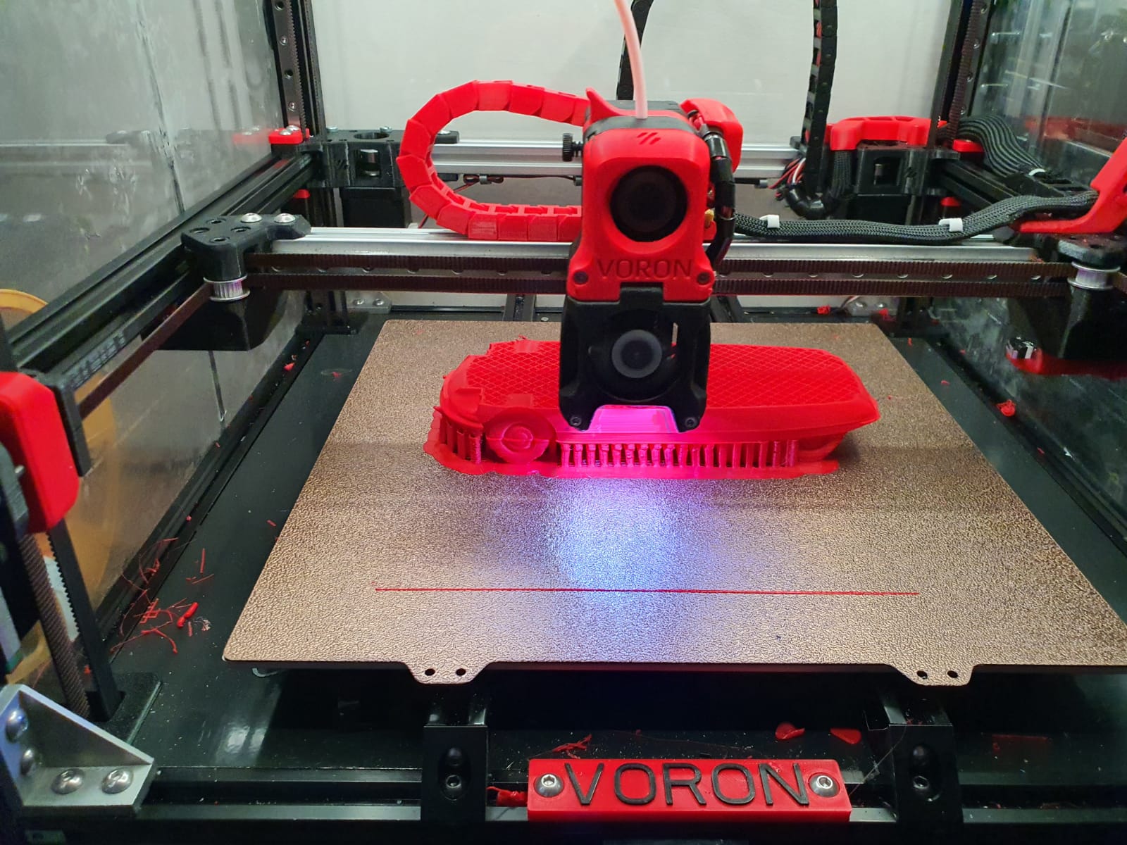
Developed from a large community, the VORON is one of the best and most reliable 3D printers. And this printer just looks really good!
Via AliExpress, Banggood, Reichelt, aluminiumopmaat.nl and plexiglas.nl I ordered all the stuff, according to the bill of materials I could download from the VORON site.
I printed the PETG parts on the Prusa mini at 0.15 fine.
The ABS parts (red and black) were printed on the Twotrees Sapphire plus. It took a lot of ‘tweeking’ before the ABS came out well but in the end I got a nice result!
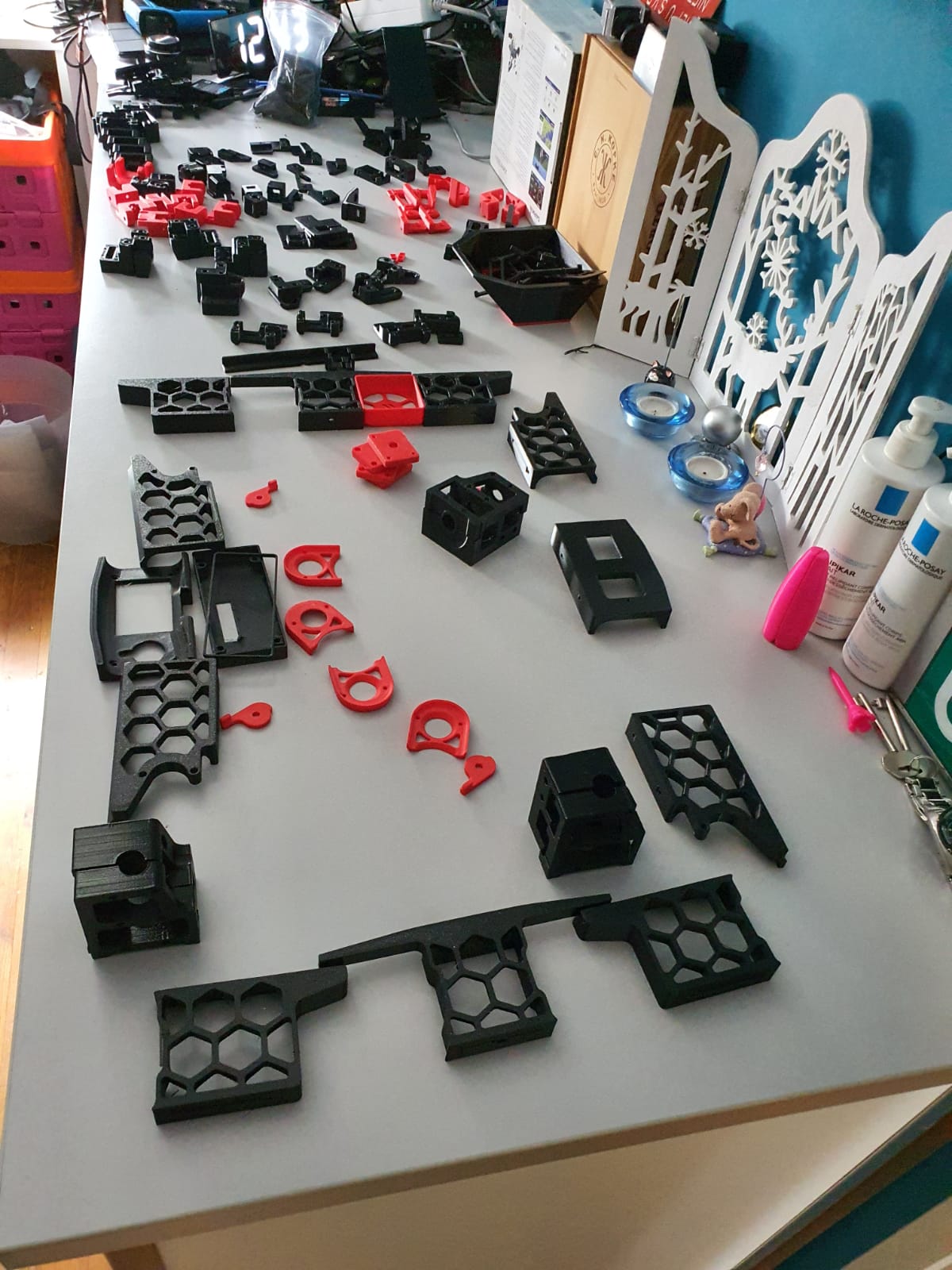
Printed parts for the Voron 2.4 300In the end, rebuilding is not really self-building and it is more based on ordering and assembling than getting to work with the saw and drill yourself. Also the necessary 8(!) linear rails of 350mm, bearings, gears, belts, motors, electronics and so on have been ordered and the rest of the necessary stuff has been printed (25-8-2020).
For the control part I have chosen one PI Raspberry PI 4B 4GB and two pieces of SKR 1.4 turbo motherboards, according to the VORON recommendation.
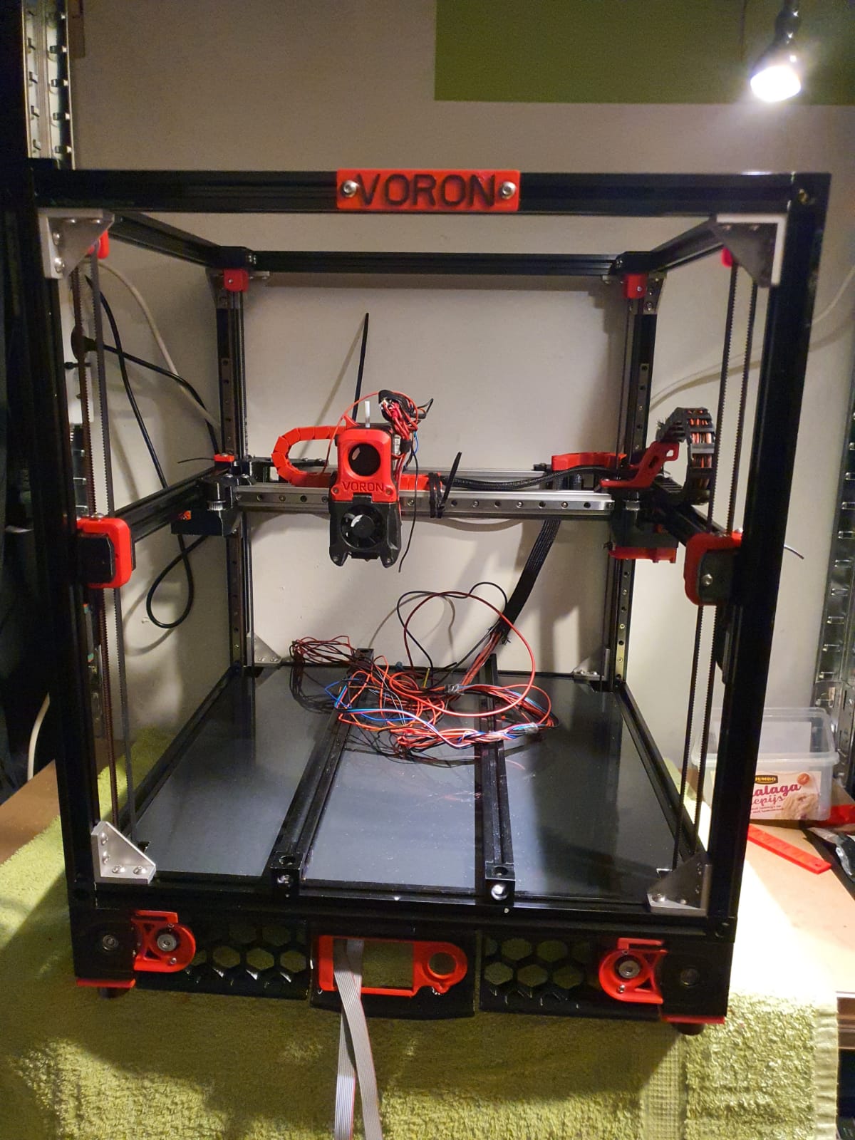
Building the Voron 2.4 with the afterburner Beta1 hotend combination is illustrated by the following pictures.
Gantry ready:
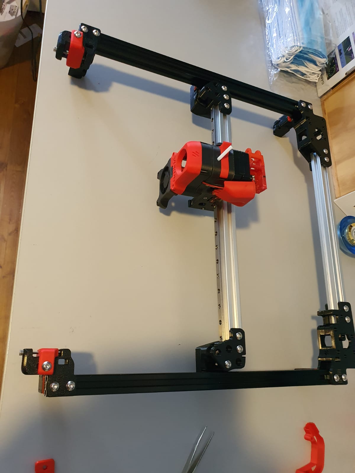
Gantry of my Voron 2.4 300Housing and skirts underside with Z-motors yet without the gantry mounted:
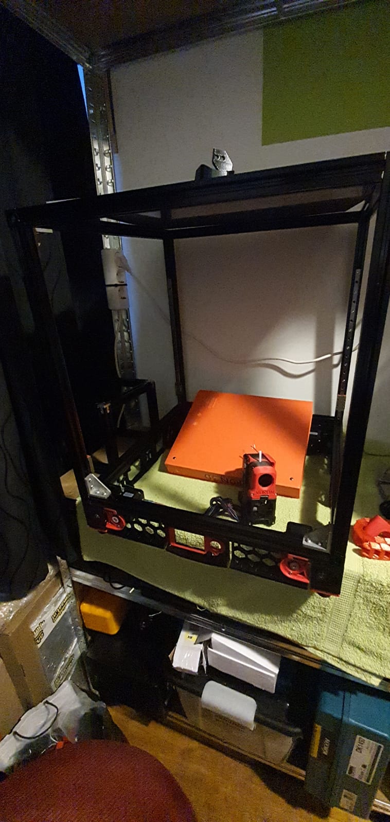
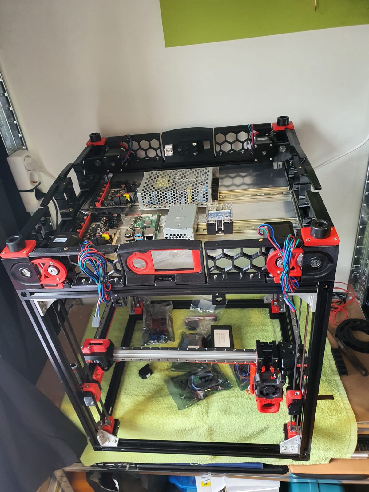
Below: The 9 mm drive belts of the 4 Z-axes placed:
And the assembled base plate with the rails and controls, power supplies and so on (printer turned over):
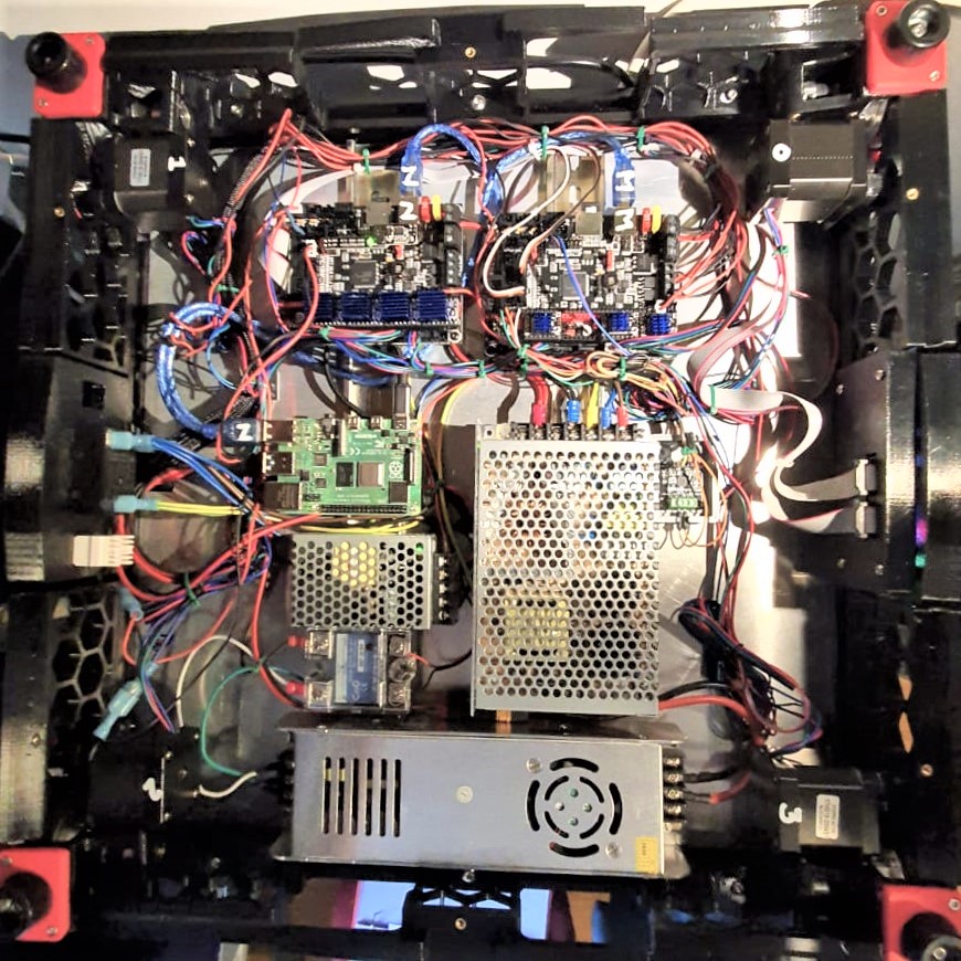
We are still waiting for the bearings for the Alpha and Beta drives in the gantry. These bearings are used to make a tension roller per 2 pieces. I had originally bought idler bearings for this purpose, but the diameter of the collar of these bearings is just too large.
Too bad but then I have to work on the Raspberry PI4B in combination with 2 times SKR V1.4 turbo motherboards. The PI will make a new config.bin via Klipper for the SKR V1.4 motherboards so the PI can drive both SKR boards at the same time. On the main board will be Alpha and Beta and the extruder plus the extruder heater, on the other (Z) board the 4 Z-motors and bed heater. By itself a Duet with expansion board could have been an option too, but the Voron designers made it with the PI, Klipper and 2 SKR boards. And I try to stay as close to the design as possible . -)
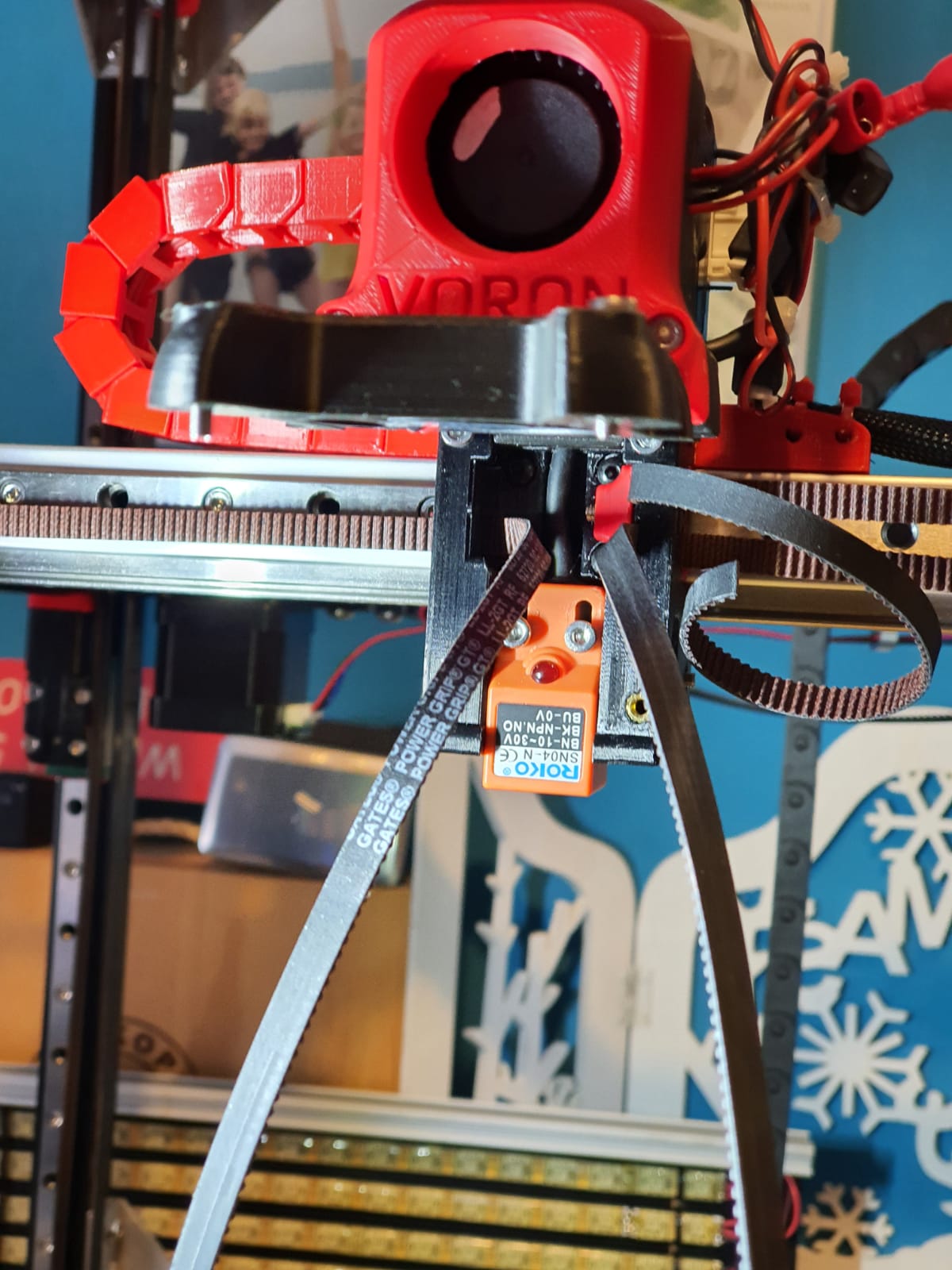
Below: Threading the straps, no picture used. Just start somewhere and you’ll end up right. Oh yes, also changed the sensor in the config from NC to NO..
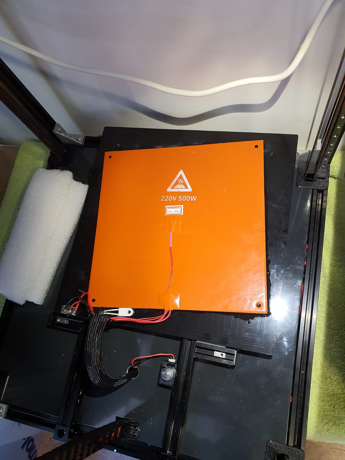
Below: In addition to the 24Volt 200 Watt hotbed nevertheless also added the 500 Watt 230V. With only the 24V version it took more than 20 minutes to get to 110 degrees Celsius…
Old:

And new— no PID run done yet..)

Below: The steel plate is placed on the sticky magnet sheet.
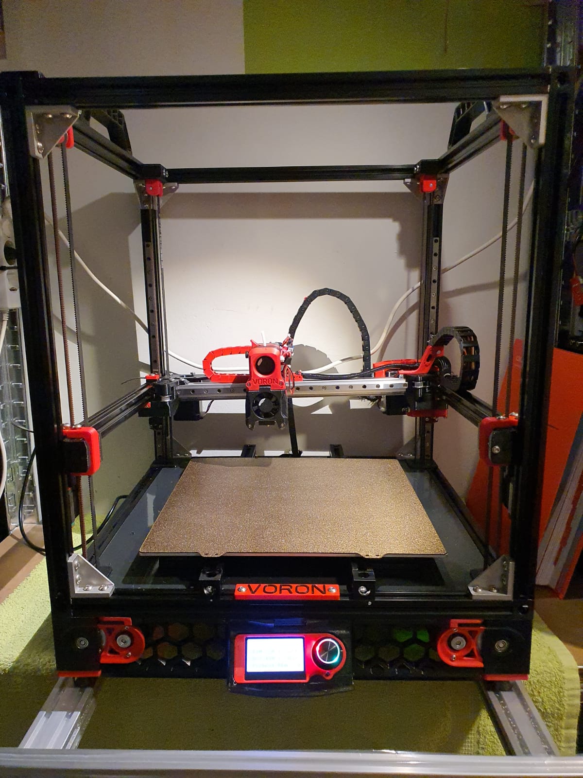
Below: First print…. I had to search for the Z offset adjustment and the extruder turned the wrong way around. Also the gantry leveling took some thought, you actually have to make the basic setting with a ruler, otherwise the leveling takes a long time. Nice is that a bed mesh leveling is not necessary anymore, but of course it can be done. You turn a home and because the nozzle always calibrates the Z on the mechanical Z endstop, and the gantry does all the leveling, you always have a good first layer. Unless the bed warps but with such a thick plate that seems almost impossible. Just to be sure, I did include a bed_mesh profile in the config.g. By the way I just used a 24 V aluminum hotbed as a base because my 8 mm 310×310 plate turned out to be a cut plate instead of sawn. And a cut sheet turns out to be non-flat on the cut sides by default, unfortunately. Flattening costs more than a new plate, maybe that will come sometime….
And with enclosure, camera and the TOP LED’s:
Afterword:
In practice, I fixed a few more minor flaws, including:
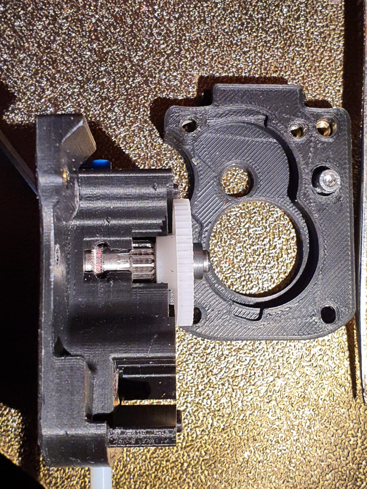
Extruder tuning. The donor extruder turned out not to pick up the filament properly.
First I tried to put a ring in between the left side of the shaft, but then the nylon gear on the right side of the shaft gets tight and the housing can’t be closed completely anymore….
I ended up using a spare set of dual drive extruder gears and swapping the set of gears. With that, the filament was properly aligned with the running path of the gears. See the picture how it was at first:
Hotend tuning
After the PID runs of hotend and heated bed, my chosen assembly of the custom ED6 heater block, the heatbreak pipe and the cooling element turned out not to fit together properly. The result was that when the filament was extracted, a thick piece was always stuck at the end. This was caused by the heatbreak pipe not fitting tightly on the nozzle. There should be no play between them. I completely demounted the filament and screwed the heatbreak pipe 2 turns less into the cooling element with red threadlocker. Let it harden for a day and then I assembled the rest. By the way, I also mounted the teflon version of the heatbreak pipe in stead of the titanium version. The tintanium version was to my experience a bit too stiff. Or my filament was too old or inferior. In any case, after the modification, everything works without problems.
Hotbed, TPU and ABS
To print TPU and ABS without brim or skirt without warping I bought a magnetic PEI steel plate with coarse profile. It really works perfectly. Both ABS at 110 degrees sticks nicely and TPU at room temperature sticks nicely too. And the removal is also without problems. Occasionally I spray a little hairspray on the plate but I don’t think that lacquer is really necessary at all. It is meant to make the removal easier.
Tension of the belts
I tried getting the belts at the same tension, this was not that easy. Finally I ended up with a mechanical way of measuring tension after putting 1 at my desired tension and comparing this as reference with the other to be compared belts. So, for the Alpha and Beta belts I first did a ‘good feeling’ setting and then I used my old trunk scale weight device to measure the tension when pulling the belt A. Then, I used the device to measure at the same place for B. And I repeated this for the 4 vertical belts.
Alignment
Aligning the machine is also a bit of a challenge…
You must assume that your frame is square and straight. You have to check this thoroughly. Both vertically, horizontally and diagonally. Then you can adjust the gantry. Loosen and remove the A and B belts. Or do the alignment BEFORE placing the belts.
Fix the horizontal position of the Gantry otherwise you can’t align at all. Place 4 equal distance blocks of about 10-15 cm under the sliders of the vertical linear rails on the lower 2020 profiles, in the 4 corners through which the gantry rests stably. I have placed position holders under all MGN9 vertical linear rails afterwards so that the rails cannot slide in the 20×20 V profile. If you use ‘regular’ 20×20 extrusion profile you don’t have a problem because there is enough ‘meat’ left for attaching your rail to the profile. With V-profile, the groove is a bit wider and it is very difficult to mount the rails neatly without tools in the groove. My frame is of V-rail profile and the gantry of plain 2020 profile.
The alignment of the gantry I started at the back. Loosening all screws a bit, including the screws of the convex connectors that hold the gantry to the linear rails. By the way, I see some builders placing these screws with multiple spring washers. I’m going to do that too…
At the rear of the gantry, push the gantry completely against the rear. There should be no gap between the XY joints and the frame. PS: Leave the endstops off for a while at this action!
While the gantry is sitting against the back, tighten the XY joints and the sliders of the X-axle as well. (the side of the endstops holder is temporarily secured with 2 screws)
Tighten the rear 2 gantry joints (with the convex surfaces) as well. This fixes the rear position at right angles.
Carefully slide the gantry forward. This should be possible without any effort. If not, check whether there is enough play (and if necessary loosen the screws) on the gantry joints at the front (with the convex surfaces). If you still don’t have a free run to the front, your frame is not good or your vertical rails are not seated properly. First check the correct positioning of your rails with your position tool (from the printed stock) and to be sure also unscrew the 4 screws on both front vertical rails. Try again if the sliding of the gantry goes smoothly. Still no good? Then reverse the procedure and start at the front. Try to set the gantry exactly level with the frame.
After adjusting: Test the alignment also halfway (vertically) and at the top!
Get the documentation, specs, config.g, macros and build docs
After my succesfull buildproject of a Voron 2.4 3d printer in the fall of 2020, I still wanted a really big 3d printer with a print surface of over 20x20x20 inch.
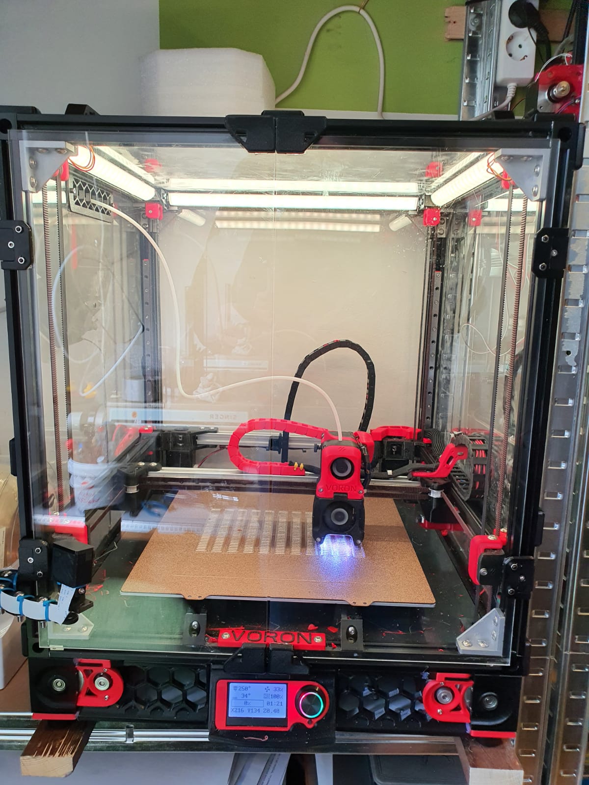
Imagine to have a print of more than double the size compared to the below picture!
During the build and at using the Voron 2.4 printer, I found the documentation on the hardware build really excellent. But, the electronics part was scattered around several places, and although the Klipper implementation is very good I have experienced that the combination of 2 SKR 1.4 turbo motherboards with an Octopi controller does not provide enough operational stability to me. And- I feel the need to control more settings than I can do with the Klipper solution. I think I probably am just more into the Duet and the reprap solution than the Klipper one, due to previous positive Duet – and MKS reprap experiences.
In a couple of previous builds I used a Duet2wifi, and I also experienced the add-ons for Duet2 like driver boards, PT100 boards and more hardware that is also very well implemented in the new RRF3+ firmware.
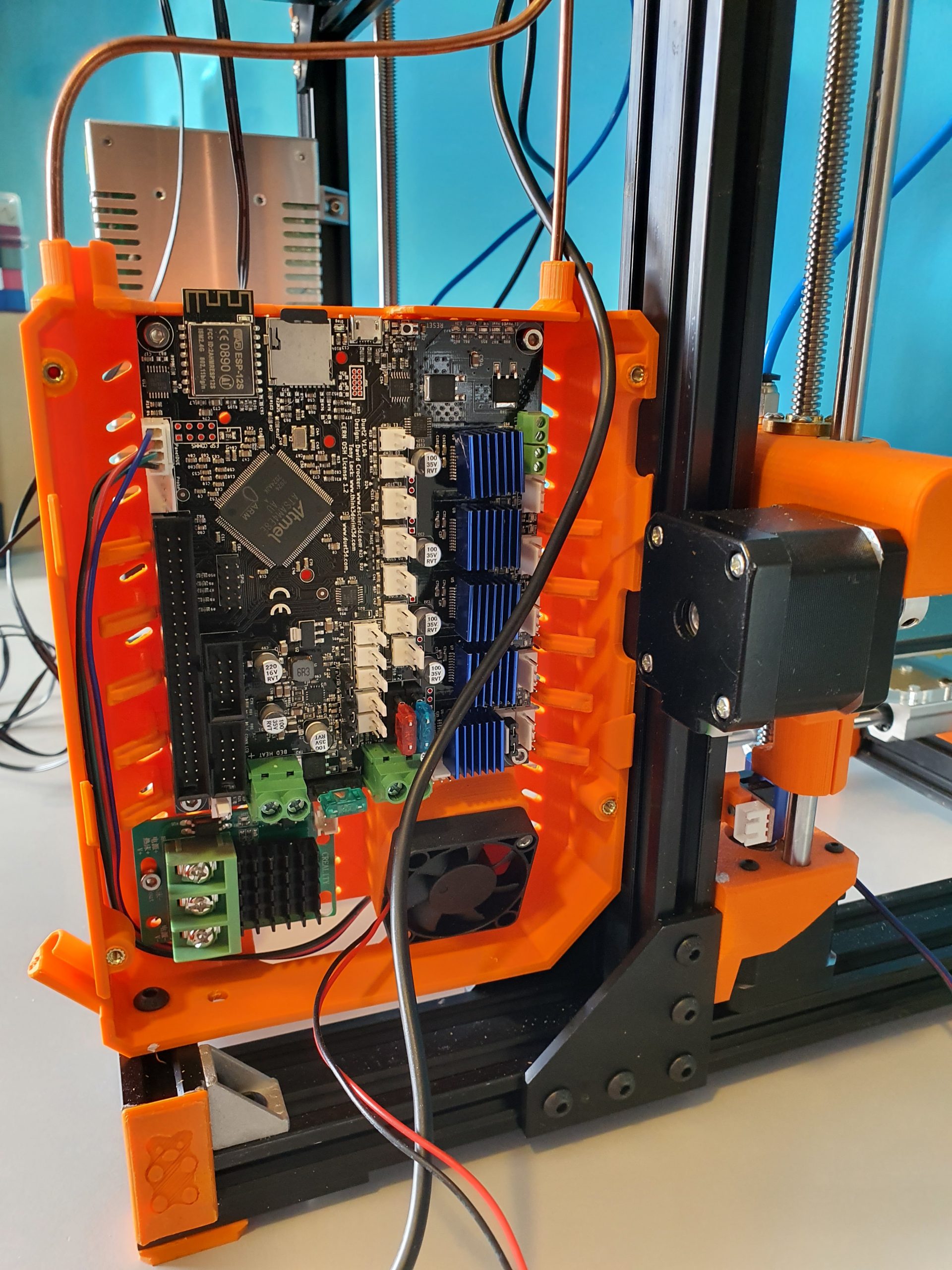
Reasons enough for me to choose the Duet2 and the 5-ports expansion board , or possibly an additional Duex board for my new to build Voron 2.4 ‘big 3d printer’.
At this page, I will share my progess on this build.
I have all required hardware laying around and since I already built a Voron 2.4, I will first focus on the electronics. For the hardware, I still need the plexiglass sides, top and front doors. I do have all extrusion, bed, bed heater 230V, linear rails, all printed parts and so on, neatly stored at home.
So, I am setting up the electronics to know beforehand that everything works well. I don’t want to start building the hardware and find out afterwards that my Duet2wifi will not do the job I want it to do.
Yesterday (October 4th,2020) I put the electronics and config.g together. I used:
The Duet2wifi board is a Chinese MKS clone with electronics version 1.02 which works fine. The expansion board is also a Chinese one, but this is a bare-bone implementation of the 5-ports driver add-on board that comes without drivers. the nice thing about this add-on board is that drivers can be plugged in directly.
The Duet2 came with firmware 2.1 installed. To get to FFR3.1, you must first install 3.0 and after this, you can move to 3.1… be aware!
After updating the paneldue and the Duet2wifi board, I activated the wifi and put the ssid and PW in. (This procedure goes via USB between PC and Duet, using a terminal emulator like YAT) This is a bit tiresome but given the security you get from it, I feel it is OK.
The settings that are needed to get the Chinese expension board to work are not too difficult. Add the Z-drives, and change some other settings. On top of this page, you can download the latest doc with all info I have, and a direct download to the adapted config and macros is available in the documentation.
The rest of the build including photos will be here later!
Update 3-2021: I recently built 2 other 3d printers using Duet2wifi boards: a cartesian I3 with independent extruders and a Delta 2GS. Not much time to work on the big Voron. I also just rebuilt my Geetech A30M (330x330x400mm build size) from the smartto board to Duet2wifi, Check ik out on this site!
I will probably not build the big Voron 3d printer after all, and if I don’t, I will rebuild my existing Voron 2.4 300×300 from Klipper, octopi and 2x SKR1.4 to Duet2wifi+Duex. That will be interesting and achievable.
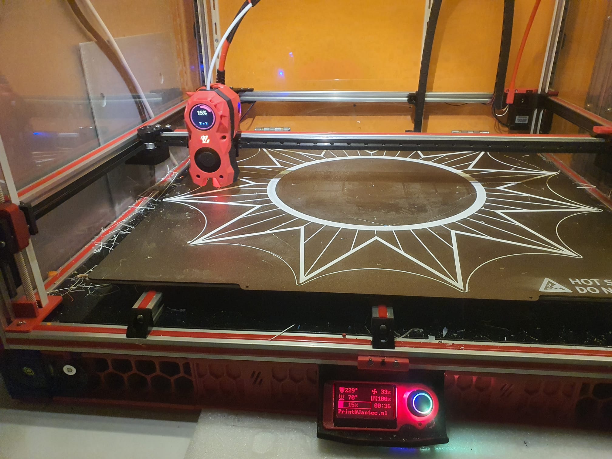
Since I am currently running 10 different 3d printers, my space is getting cramped in the house. I don’t want to expand into another room. One should be enough. Having more printers gives me the best possible fit of a specific filament type per printer.
The Voron is due to its perfect prints with ABS really only used for/with ABS or nylon.
The I3Bear dual carriage works best with dual PLA or PLA&PVA.
The Prusa mini works perfect with PETG
The I3Bear solo goes perfect with PETG or PLA.
The A30M & its mixing extruder goes perfect with PLA and/or PETG
And so on….