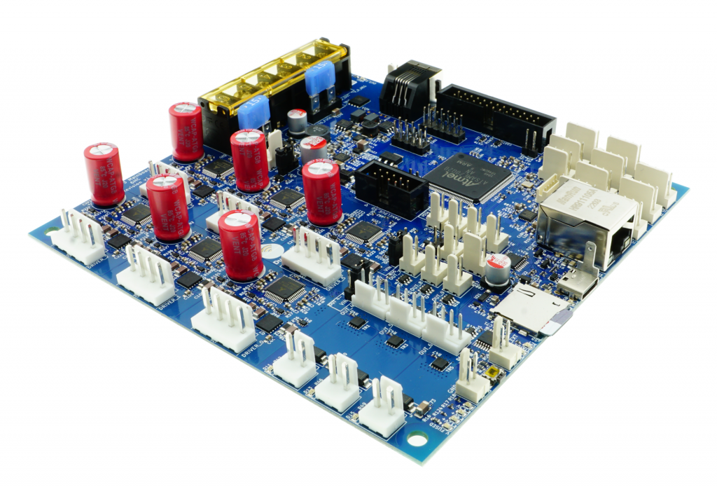
I added the timezone.lib plus arduino-additional code to the open-source code as GRA-AFCH made this for their IN-18 nixie clock with Arduino Mega : NixieClockShield_NCS318_V1_94_TZ.
This is a first version that works, but it might require some coding to be done, depending on where you live.
And THIS is HOW it works: The startup sequence is shown in the below video:
If you’re not in Western Europe, changing the timezone will be needed.
If I want to spend some more time on it, I can make it fully automated to work anywhere in the world and make the timezone setting done via the menu buttons, requires only a one time setting upon installation. Maybe later.
This 1ST version makes the NIXIE clock sync to UTC with the help of a to be connected standard GPS module . This was already in the code. Then, the clock changes to the correct time zone, including automatic shifting for summer- and wintertime!
In the code, I used the Western Europe timezone- and winter/summertime settings. Also, an example is given for a US timezone. Others can be derived from the examples that come with the newly added timezone.lib from https://github.com/JChristensen/Timezone
These are the available timezones:
// Australia Eastern Time Zone (Sydney, Melbourne)
TimeChangeRule aEDT = {“AEDT”, First, Sun, Oct, 2, 660}; // UTC + 11 hours
TimeChangeRule aEST = {“AEST”, First, Sun, Apr, 3, 600}; // UTC + 10 hours
Timezone ausET(aEDT, aEST);
// Moscow Standard Time (MSK, does not observe DST)
TimeChangeRule msk = {“MSK”, Last, Sun, Mar, 1, 180};
Timezone tzMSK(msk);
// Central European Time (Frankfurt, Paris)
TimeChangeRule CEST = {“CEST”, Last, Sun, Mar, 2, 120}; // Central European Summer Time
TimeChangeRule CET = {“CET “, Last, Sun, Oct, 3, 60}; // Central European Standard Time
Timezone CE(CEST, CET);
// United Kingdom (London, Belfast)
TimeChangeRule BST = {“BST”, Last, Sun, Mar, 1, 60}; // British Summer Time
TimeChangeRule GMT = {“GMT”, Last, Sun, Oct, 2, 0}; // Standard Time
Timezone UK(BST, GMT);
// UTC
TimeChangeRule utcRule = {“UTC”, Last, Sun, Mar, 1, 0}; // UTC
Timezone UTC(utcRule);
// US Eastern Time Zone (New York, Detroit)
TimeChangeRule usEDT = {“EDT”, Second, Sun, Mar, 2, -240}; // Eastern Daylight Time = UTC – 4 hours
TimeChangeRule usEST = {“EST”, First, Sun, Nov, 2, -300}; // Eastern Standard Time = UTC – 5 hours
Timezone usET(usEDT, usEST);
// US Central Time Zone (Chicago, Houston)
TimeChangeRule usCDT = {“CDT”, Second, Sun, Mar, 2, -300};
TimeChangeRule usCST = {“CST”, First, Sun, Nov, 2, -360};
Timezone usCT(usCDT, usCST);
// US Mountain Time Zone (Denver, Salt Lake City)
TimeChangeRule usMDT = {“MDT”, Second, Sun, Mar, 2, -360};
TimeChangeRule usMST = {“MST”, First, Sun, Nov, 2, -420};
Timezone usMT(usMDT, usMST);
// Arizona is US Mountain Time Zone but does not use DST
Timezone usAZ(usMST);
// US Pacific Time Zone (Las Vegas, Los Angeles)
TimeChangeRule usPDT = {“PDT”, Second, Sun, Mar, 2, -420};
TimeChangeRule usPST = {“PST”, First, Sun, Nov, 2, -480};
Timezone usPT(usPDT, usPST);
Be aware,the way I did this is a Q&D method since i have just hacked this into an existing piece of code, and only do a rewrite of the RTC’s original time after every sync to GPS with the new timezone and winter/summer time rules, so RTC will then become the new local time, either summer- or wintertime.
Since the time and applying the rules of timezone+ winter/summertime is continuously refreshed, not just the time is very stable, but also the changes between winter- and summertime and vice versa are automated.
The required arduino libraries are on the GRA-AFCH Github pagine:
https://github.com/afch/NixieClock
OR-just download the zipped Libraries from our website.
It works really well, please see the zipped file here or copy/paste the arduino code below (you will need some additional files than can only be retreived from the zip-file below, though).
NixieClockShield_NCS318_V1_94_TZ.ino
NixieClockShield_NCS318_V1_94_TZ.ino:
const String FirmwareVersion = “0196TZ”;
const char HardwareVersion[] PROGMEM = {“NCS318/568 FW 1.94TZ 2021_04_04 Jantec.nl add-on for Timezones for HW 1.x HV5122 or HV5222”};
//// This ‘TZ’ firmware addition delivers automated Summer/Winter time changes based on your local time zone settings ////
//// Jantec.nl 2023-04-04 The Netherlands, Amsterdam. Please share and re-use! ////
//// This can and may be used in any CLOCK program, with possibly specific minor alteration, due to different libraries and do on ////
//// All of my add-ons are specified in the code! Cheers, Jantec.nl, NL ////
//// The approach here is to automatically change the EEPROM hours setting according to the SUMMER/WINTER timecheme ////
//// meaning: Put in the register: a) the time zone (=normal winter time) versus UTC and b) at the switching times the summer ‘+1’ change versus ‘normal’wintertime ///
//// If the user changes the hours setting, this will be overruled at every programmed time change related to summer/ winter time
//Format _X.XXX_
//NIXIE CLOCK SHIELD NCS318/568 for HW 1.x by GRA & AFCH (fominalec@gmail.com)
//1.94 26.02.2021
//Added: Сhecking the presence of a gps receiver when turned on.
//Return to the previous gps parser
//1.92 21.01.2021
//Added: defines for GPS receiver types
//1.91 29.07.2020
//The driver has been changed to support BOTH HV5122 and HV5222 registers (switching using resistor R5222 Arduino pin No. 8)
//1.90 08.06.2020
//Fixed: GPS timezone issue: added breakTime(now(), tm) to adjustTime function at Time.cpp
//1.89 03.04.2020
//Dots sync with seconds
//1.88 26.03.2020
//GPS synchronization algorithm has been changed (again)
//1.86 23.02.2020
//GPS synchronization algorithm changed
//1.85.3 23.02.2020
//Added: DS3231 internal temperature sensor self test: 5 beeps if fail.
//1.85.2 21.02.2020
//Fixed: Bug with time zones more than +-9
// GPS parser has been replaced by NEOGPS
//1.85.1 05.01.2020
//Value of “HardwareVersion” was changed to NCS318/568
//1.85 14.06.2019
//indication is working inside interrupt (only for Arduino Mega), driver v1.3 is required
//Added: support programmable leds ws2812b
//Some performance optimizations
//1.84 08.04.2018
//LEDs functions moved to external file
//LEDs freezing while music (or sound) played.
//SPI Setup moved driver’s file
//1.83 02.08.2018 (Driver v 1.1 is required)
//Fixed: Temp. reading speed fixed
//Fixed: Dots mixed up (driver was updated to v. 1.1)
//Fixed: RGB LEDs reading from EEPROM
//Fixed: Check for entering data from GPS in range
//1.82 18.07.2018 Dual Date Format
//1.81 18.02.2018 Temp. sensor present analyze
//1.80 06.08.2017
//Added: Date and Time GPS synchronization
//1.70 30.07.2017
//Added IR remote control support (Sony RM-X151) (“MODE”, “UP”, “DOWN”)
//1.60 24_07_2017
//Added: Temperature reading mode in menu and slot machine transaction
//1.0.31 27_04_2017
//Added: antipoisoning effect – slot machine
//1.021 31.01.2017
//Added: time synchronizing each 10 seconds
//Fixed: not correct time reading from RTC while start up
//1.02 17.10.2016
//Fixed: RGB color controls
//Update to Arduino IDE 1.6.12 (Time.h replaced to TimeLib.h)
//1.01
//Added RGB LEDs lock(by UP and Down Buttons)
//Added Down and Up buttons pause and resume self testing
//25.09.2016 update to HW ver 1.1
//25.05.2016
//#define tubes8
#define tubes6
//#define tubes4
#include <SPI.h>
#include <Wire.h>
#include <ClickButton.h>
#include <TimeLib.h>
#ifndef GRA_AND_AFCH_TIME_LIB_MOD
#error The “Time (TimeLib)” library modified by GRA and AFCH must be used!
#endif
//// THIS IS NEW, related to TIMEZONE add-on:
#include <Timezone.h>//https://github.com/JChristensen/Timezone
//Central European Time (Frankfurt, Paris)
TimeChangeRule myDST = {“CEST”, Last, Sun, Mar, 26, 120}; //Central European Summer Time//Daylight time = UTC +2 hours
TimeChangeRule mySTD = {“CET “, Last, Sun, Oct, 3, 60}; //Central European Standard Time (Winter)//Daylight time = UTC +1 hour
Timezone myTZ(myDST, mySTD);
//ADD AND REPLACE THE ABOVE FOR ANY OTHER REQUIRED TIMEZONE FROM THE EXAMPLES IN JChistensen’s exaples folders
// US Eastern Time Zone (New York, Detroit)
//TimeChangeRule myDST = {“EDT”, Second, Sun, Mar, 2, -240}; //Daylight time = UTC – 4 hours
//TimeChangeRule mySTD = {“EST”, First, Sun, Nov, 2, -300}; //Daylight time = UTC – 4 hours
//Timezone myTZ(myDST, mySTD);
TimeChangeRule *tcr; //pointer to the time change rule, use to get the TZ abbrev
time_t utc;
//// end of this add-on for TIMEZONE
#include <Tone.h>
#include <EEPROM.h>
#include “doIndication318_HW1.x.h”
#include <OneWire.h>
//IR remote control /////////// START /////////////////////////////
#if defined(__AVR_ATmega1280__) || defined(__AVR_ATmega2560__)
#define GPS_SYNC_INTERVAL 1800000 // in milliseconds
//#define GPS_SYNC_INTERVAL 180000 //3 minutes
unsigned long Last_Time_GPS_Sync = 0;
//bool GPS_Sync_Flag = false;
//uint32_t GPS_Sync_Interval=120000; // 2 minutes
uint32_t GPS_Sync_Interval = 60000; // first try = 1 minute
uint32_t MillsNow=0;
#define TIME_TO_TRY 60000 //1 minute
bool AttMsgWasShowed=false;
#define GPS_BUFFER_LENGTH 83
char GPS_Package[GPS_BUFFER_LENGTH];
byte GPS_position = 0;
struct GPS_DATE_TIME
{
byte GPS_hours;
byte GPS_minutes;
byte GPS_seconds;
byte GPS_day;
byte GPS_mounth;
int GPS_year;
bool GPS_Valid_Data = false;
unsigned long GPS_Data_Parsed_time;
};
GPS_DATE_TIME GPS_Date_Time;
#define PreZero(digit) ((abs(digit)<10)?”0″+String(abs(digit)):String(abs(digit)))
#include <IRremote.h>
int RECV_PIN = 4;
IRrecv irrecv(RECV_PIN);
decode_results IRresults;
// buttons codes for remote controller Sony RM-X151
#define IR_BUTTON_UP_CODE 0x6621
#define IR_BUTTON_DOWN_CODE 0x2621
#define IR_BUTTON_MODE_CODE 0x7121
class IRButtonState
{
public:
int PAUSE_BETWEEN_PACKETS = 50;
int PACKETS_QTY_IN_LONG_PRESS = 18;
private:
bool Flag = 0;
byte CNT_packets = 0;
unsigned long lastPacketTime = 0;
bool START_TIMER = false;
int _buttonCode;
public: IRButtonState::IRButtonState(int buttonCode)
{
_buttonCode = buttonCode;
}
public: int IRButtonState::checkButtonState(int receivedCode)
{
if (((millis() – lastPacketTime) > PAUSE_BETWEEN_PACKETS) && (START_TIMER == true))
{
START_TIMER = false;
if (CNT_packets >= 2) {
Flag = 0;
CNT_packets = 0;
START_TIMER = false;
return 1;
}
else {
Flag = 0;
CNT_packets = 0;
return 0;
}
}
else
{
if (receivedCode == _buttonCode) { Flag = 1;}
else
{
if (!(Flag == 1)) {return 0;}
else
{
if (!(receivedCode == 0xFFFFFFFF)) {return 0;}
}
}
CNT_packets++;
lastPacketTime = millis();
START_TIMER = true;
if (CNT_packets >= PACKETS_QTY_IN_LONG_PRESS) {
Flag = 0;
CNT_packets = 0;
START_TIMER = false;
return -1;
}
else {return 0;}
}
}
};
IRButtonState IRModeButton(IR_BUTTON_MODE_CODE);
IRButtonState IRUpButton(IR_BUTTON_UP_CODE);
IRButtonState IRDownButton(IR_BUTTON_DOWN_CODE);
#endif
int ModeButtonState = 0;
int UpButtonState = 0;
int DownButtonState = 0;
//IR remote control /////////// START /////////////////////////////
/*#define GPS_BUFFER_LENGTH 83
char GPS_Package[GPS_BUFFER_LENGTH];
byte GPS_position=0;
struct GPS_DATE_TIME
{
byte GPS_hours;
byte GPS_minutes;
byte GPS_seconds;
byte GPS_day;
byte GPS_mounth;
int GPS_year;
bool GPS_Valid_Data=false;
unsigned long GPS_Data_Parsed_time;
};
*/
//GPS_DATE_TIME GPS_Date_Time;
unsigned long GPS_Data_Parsed_time;
boolean UD, LD; // DOTS control;
byte data[12];
byte addr[8];
int celsius, fahrenheit;
#define RedLedPin 9 //MCU WDM output for red LEDs 9-g
#define GreenLedPin 6 //MCU WDM output for green LEDs 6-b
#define BlueLedPin 3 //MCU WDM output for blue LEDs 3-r
#define pinSet A0
#define pinUp A2
#define pinDown A1
//#define pinBuzzer 2
const byte pinBuzzer = 2; // pomenyal
#define pinUpperDots 12 //HIGH value light a dots
#define pinLowerDots 8 //HIGH value light a dots
#define pinTemp 7
bool RTC_present;
#define US_DateFormat 1
#define EU_DateFormat 0
//bool DateFormat=EU_DateFormat;
OneWire ds(pinTemp);
bool TempPresent = false;
#define CELSIUS 0
#define FAHRENHEIT 1
String stringToDisplay = “000000”; // Content of this string will be displayed on tubes (must be 6 chars length)
int menuPosition = 0;
// 0 – time
// 1 – date
// 2 – alarm
// 3 – 12/24 hours mode
// 4 – Temperature
// 5 – TimeZone* (Only for Ardiono Mega)
byte blinkMask = B00000000; //bit mask for blinkin digits (1 – blink, 0 – constant light)
int blankMask = B00000000; //bit mask for digits (1 – off, 0 – on)
byte dotPattern = B00000000; //bit mask for separeting dots (1 – on, 0 – off)
//B10000000 – upper dots
//B01000000 – lower dots
#define DS1307_ADDRESS 0x68
byte zero = 0x00; //workaround for issue #527
int RTC_hours, RTC_minutes, RTC_seconds, RTC_day, RTC_month, RTC_year, RTC_day_of_week;
#define TimeIndex 0
#define DateIndex 1
#define AlarmIndex 2
#define hModeIndex 3
#define TemperatureIndex 4
#define TimeZoneIndex 5
#define TimeHoursIndex 6
#define TimeMintuesIndex 7
#define TimeSecondsIndex 8
#define DateFormatIndex 9
#define DateDayIndex 10
#define DateMonthIndex 11
#define DateYearIndex 12
#define AlarmHourIndex 13
#define AlarmMinuteIndex 14
#define AlarmSecondIndex 15
#define Alarm01 16
#define hModeValueIndex 17
#define DegreesFormatIndex 18
#define HoursOffsetIndex 19
#define FirstParent TimeIndex
#define LastParent TimeZoneIndex
#define SettingsCount (HoursOffsetIndex+1)
#define NoParent 0
#define NoChild 0
//——————————-0——–1——–2——-3——–4——–5——–6——–7——–8——–9———-10——-11———12———13——-14——-15———16———17——–18———-19
// names: Time, Date, Alarm, 12/24, Temperature,TimeZone,hours, mintues, seconds, DateFormat, day, month, year, hour, minute, second alarm01 hour_format Deg.FormIndex HoursOffset
// 1 1 1 1 1 1 1 1 1 1 1 1 1 1 1 1 1 1 1 1
int parent[SettingsCount] = {NoParent, NoParent, NoParent, NoParent,NoParent,NoParent,1, 1, 1, 2, 2, 2, 2, 3, 3, 3, 3, 4, 5, 6};
int firstChild[SettingsCount] = {6, 9, 13, 17, 18, 19, 0, 0, 0, NoChild, 0, 0, 0, 0, 0, 0, 0, 0, 0, 0};
int lastChild[SettingsCount] = { 8, 12, 16, 17, 18, 19, 0, 0, 0, NoChild, 0, 0, 0, 0, 0, 0, 0, 0, 0, 0};
int value[SettingsCount] = { 0, 0, 0, 0, 0, 0, 0, 0, 0, EU_DateFormat, 0, 0, 0, 0, 0, 0, 0, 24, 0, 2};
int maxValue[SettingsCount] = { 0, 0, 0, 0, 0, 0, 23, 59, 59, US_DateFormat, 31, 12, 99, 23, 59, 59, 1, 24, FAHRENHEIT, 14};
int minValue[SettingsCount] = { 0, 0, 0, 12, 0, 0, 00, 00, 00, EU_DateFormat, 1, 1, 00, 00, 00, 00, 0, 12, CELSIUS, -12};
int blinkPattern[SettingsCount] = {
B00000000, //0
B00000000, //1
B00000000, //2
B00000000, //3
B00000000, //4
B00000000, //5
B00000011, //6
B00001100, //7
B00110000, //8
B00111111, //9
B00000011, //10
B00001100, //11
B00110000, //12
B00000011, //13
B00001100, //14
B00110000, //15
B11000000, //16
B00001100, //17
B00111111, //18
B00000011, //19
};
bool editMode = false;
long downTime = 0;
long upTime = 0;
const long settingDelay = 150;
bool BlinkUp = false;
bool BlinkDown = false;
unsigned long enteringEditModeTime = 0;
bool RGBLedsOn = true;
#define RGBLEDsEEPROMAddress 0
#define HourFormatEEPROMAddress 1
#define AlarmTimeEEPROMAddress 2 //3,4,5
#define AlarmArmedEEPROMAddress 6
#define LEDsLockEEPROMAddress 7
#define LEDsRedValueEEPROMAddress 8
#define LEDsGreenValueEEPROMAddress 9
#define LEDsBlueValueEEPROMAddress 10
#define DegreesFormatEEPROMAddress 11
#define HoursOffsetEEPROMAddress 12
#define DateFormatEEPROMAddress 13
//buttons pins declarations
ClickButton setButton(pinSet, LOW, CLICKBTN_PULLUP);
ClickButton upButton(pinUp, LOW, CLICKBTN_PULLUP);
ClickButton downButton(pinDown, LOW, CLICKBTN_PULLUP);
///////////////////
Tone tone1;
#define isdigit(n) (n >= ‘0’ && n <= ‘9’)
//char *song = “MissionImp:d=16,o=6,b=95:32d,32d#,32d,32d#,32d,32d#,32d,32d#,32d,32d,32d#,32e,32f,32f#,32g,g,8p,g,8p,a#,p,c7,p,g,8p,g,8p,f,p,f#,p,g,8p,g,8p,a#,p,c7,p,g,8p,g,8p,f,p,f#,p,a#,g,2d,32p,a#,g,2c#,32p,a#,g,2c,a#5,8c,2p,32p,a#5,g5,2f#,32p,a#5,g5,2f,32p,a#5,g5,2e,d#,8d”;
char *song = “PinkPanther:d=4,o=5,b=160:8d#,8e,2p,8f#,8g,2p,8d#,8e,16p,8f#,8g,16p,8c6,8b,16p,8d#,8e,16p,8b,2a#,2p,16a,16g,16e,16d,2e”;
//char *song=”VanessaMae:d=4,o=6,b=70:32c7,32b,16c7,32g,32p,32g,32p,32d#,32p,32d#,32p,32c,32p,32c,32p,32c7,32b,16c7,32g#,32p,32g#,32p,32f,32p,16f,32c,32p,32c,32p,32c7,32b,16c7,32g,32p,32g,32p,32d#,32p,32d#,32p,32c,32p,32c,32p,32g,32f,32d#,32d,32c,32d,32d#,32c,32d#,32f,16g,8p,16d7,32c7,32d7,32a#,32d7,32a,32d7,32g,32d7,32d7,32p,32d7,32p,32d7,32p,16d7,32c7,32d7,32a#,32d7,32a,32d7,32g,32d7,32d7,32p,32d7,32p,32d7,32p,32g,32f,32d#,32d,32c,32d,32d#,32c,32d#,32f,16c”;
//char *song=”DasBoot:d=4,o=5,b=100:d#.4,8d4,8c4,8d4,8d#4,8g4,a#.4,8a4,8g4,8a4,8a#4,8d,2f.,p,f.4,8e4,8d4,8e4,8f4,8a4,c.,8b4,8a4,8b4,8c,8e,2g.,2p”;
//char *song=”Scatman:d=4,o=5,b=200:8b,16b,32p,8b,16b,32p,8b,2d6,16p,16c#.6,16p.,8d6,16p,16c#6,8b,16p,8f#,2p.,16c#6,8p,16d.6,16p.,16c#6,16b,8p,8f#,2p,32p,2d6,16p,16c#6,8p,16d.6,16p.,16c#6,16a.,16p.,8e,2p.,16c#6,8p,16d.6,16p.,16c#6,16b,8p,8b,16b,32p,8b,16b,32p,8b,2d6,16p,16c#.6,16p.,8d6,16p,16c#6,8b,16p,8f#,2p.,16c#6,8p,16d.6,16p.,16c#6,16b,8p,8f#,2p,32p,2d6,16p,16c#6,8p,16d.6,16p.,16c#6,16a.,16p.,8e,2p.,16c#6,8p,16d.6,16p.,16c#6,16a,8p,8e,2p,32p,16f#.6,16p.,16b.,16p.”;
//char *song=”Popcorn:d=4,o=5,b=160:8c6,8a#,8c6,8g,8d#,8g,c,8c6,8a#,8c6,8g,8d#,8g,c,8c6,8d6,8d#6,16c6,8d#6,16c6,8d#6,8d6,16a#,8d6,16a#,8d6,8c6,8a#,8g,8a#,c6″;
//char *song=”WeWishYou:d=4,o=5,b=200:d,g,8g,8a,8g,8f#,e,e,e,a,8a,8b,8a,8g,f#,d,d,b,8b,8c6,8b,8a,g,e,d,e,a,f#,2g,d,g,8g,8a,8g,8f#,e,e,e,a,8a,8b,8a,8g,f#,d,d,b,8b,8c6,8b,8a,g,e,d,e,a,f#,1g,d,g,g,g,2f#,f#,g,f#,e,2d,a,b,8a,8a,8g,8g,d6,d,d,e,a,f#,2g”;
#define OCTAVE_OFFSET 0
char *p;
int notes[] = { 0,
NOTE_C4, NOTE_CS4, NOTE_D4, NOTE_DS4, NOTE_E4, NOTE_F4, NOTE_FS4, NOTE_G4, NOTE_GS4, NOTE_A4, NOTE_AS4, NOTE_B4,
NOTE_C5, NOTE_CS5, NOTE_D5, NOTE_DS5, NOTE_E5, NOTE_F5, NOTE_FS5, NOTE_G5, NOTE_GS5, NOTE_A5, NOTE_AS5, NOTE_B5,
NOTE_C6, NOTE_CS6, NOTE_D6, NOTE_DS6, NOTE_E6, NOTE_F6, NOTE_FS6, NOTE_G6, NOTE_GS6, NOTE_A6, NOTE_AS6, NOTE_B6,
NOTE_C7, NOTE_CS7, NOTE_D7, NOTE_DS7, NOTE_E7, NOTE_F7, NOTE_FS7, NOTE_G7, NOTE_GS7, NOTE_A7, NOTE_AS7, NOTE_B7
};
int fireforks[] = {0, 0, 1, //1
-1, 0, 0, //2
0, 1, 0, //3
0, 0, -1, //4
1, 0, 0, //5
0, -1, 0
}; //array with RGB rules (0 – do nothing, -1 – decrese, +1 – increse
void setRTCDateTime(byte h, byte m, byte s, byte d, byte mon, byte y, byte w = 1);
int functionDownButton = 0;
int functionUpButton = 0;
bool LEDsLock = false;
//antipoisoning transaction
bool modeChangedByUser = false;
bool transactionInProgress = false; //antipoisoning transaction
#define timeModePeriod 60000
#define dateModePeriod 5000
long modesChangePeriod = timeModePeriod;
//end of antipoisoning transaction
bool GPS_sync_flag=false;
extern const int LEDsDelay;
/*******************************************************************************************************
Init Programm
*******************************************************************************************************/
void setup()
{
Wire.begin();
//setRTCDateTime(23,40,00,25,7,15,1);
Serial.begin(115200);
#if defined(__AVR_ATmega1280__) || defined(__AVR_ATmega2560__)
Serial1.begin(9600);
digitalWrite(19, HIGH);
#endif
if (EEPROM.read(HourFormatEEPROMAddress) != 12) value[hModeValueIndex] = 24; else value[hModeValueIndex] = 12;
if (EEPROM.read(RGBLEDsEEPROMAddress) != 0) RGBLedsOn = true; else RGBLedsOn = false;
if (EEPROM.read(AlarmTimeEEPROMAddress) == 255) value[AlarmHourIndex] = 0; else value[AlarmHourIndex] = EEPROM.read(AlarmTimeEEPROMAddress);
if (EEPROM.read(AlarmTimeEEPROMAddress + 1) == 255) value[AlarmMinuteIndex] = 0; else value[AlarmMinuteIndex] = EEPROM.read(AlarmTimeEEPROMAddress + 1);
if (EEPROM.read(AlarmTimeEEPROMAddress + 2) == 255) value[AlarmSecondIndex] = 0; else value[AlarmSecondIndex] = EEPROM.read(AlarmTimeEEPROMAddress + 2);
if (EEPROM.read(AlarmArmedEEPROMAddress) == 255) value[Alarm01] = 0; else value[Alarm01] = EEPROM.read(AlarmArmedEEPROMAddress);
if (EEPROM.read(LEDsLockEEPROMAddress) == 255) LEDsLock = false; else LEDsLock = EEPROM.read(LEDsLockEEPROMAddress);
if (EEPROM.read(DegreesFormatEEPROMAddress) == 255) value[DegreesFormatIndex] = CELSIUS; else value[DegreesFormatIndex] = EEPROM.read(DegreesFormatEEPROMAddress);
if (EEPROM.read(HoursOffsetEEPROMAddress) == 255) value[HoursOffsetIndex] = value[HoursOffsetIndex]; else value[HoursOffsetIndex] = EEPROM.read(HoursOffsetEEPROMAddress) + minValue[HoursOffsetIndex];
//// needed to set this HoursOffsetIndex variable to 0 since we will use the timezone lib (local timezone and summer/winter time add-ons by Jantec.nl)
value[HoursOffsetIndex] = 0;
EEPROM.write(HoursOffsetEEPROMAddress, 0);
if (EEPROM.read(DateFormatEEPROMAddress) == 255) value[DateFormatIndex] = value[DateFormatIndex]; else value[DateFormatIndex] = EEPROM.read(DateFormatEEPROMAddress);
//Serial.print(F(“led lock=”));
//Serial.println(LEDsLock);
pinMode(RedLedPin, OUTPUT);
pinMode(GreenLedPin, OUTPUT);
pinMode(BlueLedPin, OUTPUT);
tone1.begin(pinBuzzer);
song = parseSong(song);
pinMode(LEpin, OUTPUT);
// SPI setup
SPISetup();
LEDsSetup();
//buttons pins inits
pinMode(pinSet, INPUT_PULLUP);
pinMode(pinUp, INPUT_PULLUP);
pinMode(pinDown, INPUT_PULLUP);
////////////////////////////
pinMode(pinBuzzer, OUTPUT);
//buttons objects inits
setButton.debounceTime = 20; // Debounce timer in ms
setButton.multiclickTime = 30; // Time limit for multi clicks
setButton.longClickTime = 2000; // time until “held-down clicks” register
upButton.debounceTime = 20; // Debounce timer in ms
upButton.multiclickTime = 30; // Time limit for multi clicks
upButton.longClickTime = 2000; // time until “held-down clicks” register
downButton.debounceTime = 20; // Debounce timer in ms
downButton.multiclickTime = 30; // Time limit for multi clicks
downButton.longClickTime = 2000; // time until “held-down clicks” register
#if defined(__AVR_ATmega1280__) || defined(__AVR_ATmega2560__)
timerSetup();
#endif
//!!!!!!!!!!!!!!!!!!!!!!!!!!!!!!!!!!!!!!!!!!!!!!!!
doTest();
//!!!!!!!!!!!!!!!!!!!!!!!!!!!!!!!!!!!!!!!!!!!!!!!
if (LEDsLock == 1)
{
setLEDsFromEEPROM();
}
getRTCTime();
byte prevSeconds = RTC_seconds;
unsigned long RTC_ReadingStartTime = millis();
RTC_present = true;
while (prevSeconds == RTC_seconds)
{
getRTCTime();
//Serial.println(RTC_seconds);
if ((millis() – RTC_ReadingStartTime) > 3000)
{
#ifdef DEBUG
Serial.println(F(“Warning! RTC DON’T RESPOND!”));
#endif
RTC_present = false;
break;
}
}
setTime(RTC_hours, RTC_minutes, RTC_seconds, RTC_day, RTC_month, RTC_year);
#if defined(__AVR_ATmega1280__) || defined(__AVR_ATmega2560__)
irrecv.blink13(false);
irrecv.enableIRIn(); // Start the receiver
#endif
//// add-ons for TIMEZONE
time_t utc = now();
time_t local = myTZ.toLocal(utc, &tcr);
Serial.println();
printDateTime(utc, “UTC”);
printDateTime(local, tcr -> abbrev);
delay(1000);//was 10000
//// end of add-ons for TIMEZONE
}
int rotator = 0; //index in array with RGB “rules” (increse by one on each 255 cycles)
int cycle = 0; //cycles counter
int RedLight = 255;
int GreenLight = 0;
int BlueLight = 0;
unsigned long prevTime = 0; // time of lase tube was lit
unsigned long prevTime4FireWorks = 0; //time of last RGB changed
//int minuteL=0; //младшая цифра минут
/***************************************************************************************************************
MAIN Programm
***************************************************************************************************************/
void loop() {
if (((millis() % 10000) == 0) && (RTC_present)) //synchronize with RTC every 10 seconds
{
getRTCTime();
setTime(RTC_hours, RTC_minutes, RTC_seconds, RTC_day, RTC_month, RTC_year);
// 4 lines of time zone & winter/summer time additions by Jantec.nl 2023 0404
time_t utc = now();
time_t local = myTZ.toLocal(utc, &tcr);
setTime(myTZ.toLocal(utc, &tcr));
EEPROM.write(DateFormatEEPROMAddress, value[myTZ.toLocal(utc, &tcr)]);
//Serial.println(F(“Sync”));
}
#if defined(__AVR_ATmega1280__) || defined(__AVR_ATmega2560__)
MillsNow=millis();
if ((MillsNow – Last_Time_GPS_Sync) > GPS_Sync_Interval)
{
//GPS_Sync_Interval = GPS_SYNC_INTERVAL; // <—-!
//GPS_Sync_Flag = 0;
if (AttMsgWasShowed==false)
{
Serial.println(F(“Attempt to sync with GPS.”));
AttMsgWasShowed=true;
}
GetDataFromSerial1();
//SyncWithGPS();
}
if ((MillsNow – Last_Time_GPS_Sync) > GPS_Sync_Interval + TIME_TO_TRY)
{
Last_Time_GPS_Sync=MillsNow; //if it is not possible to synchronize within the allotted time TIME_TO_TRY, then we postpone attempts to the next time interval.
//GPS_Sync_Flag = 1;
//GPS_Sync_Interval = GPS_SYNC_INTERVAL;
Serial.println(F(“All attempts were unsuccessful.”));
AttMsgWasShowed=false;
}
IRresults.value = 0;
if (irrecv.decode(&IRresults)) {
Serial.println(IRresults.value, HEX);
irrecv.resume(); // Receive the next value
}
ModeButtonState = IRModeButton.checkButtonState(IRresults.value);
if (ModeButtonState == 1) Serial.println(F(“Mode short”));
if (ModeButtonState == -1) Serial.println(F(“Mode long….”));
UpButtonState = IRUpButton.checkButtonState(IRresults.value);
if (UpButtonState == 1) Serial.println(F(“Up short”));
if (UpButtonState == -1) Serial.println(F(“Up long….”));
DownButtonState = IRDownButton.checkButtonState(IRresults.value);
if (DownButtonState == 1) Serial.println(F(“Down short”));
if (DownButtonState == -1) Serial.println(F(“Down long….”));
#else
ModeButtonState=0;
UpButtonState=0;
DownButtonState=0;
#endif
p = playmusic(p);
if ((millis() – prevTime4FireWorks) > LEDsDelay)
{
rotateFireWorks(); //change color (by 1 step)
prevTime4FireWorks = millis();
}
if ((menuPosition == TimeIndex) || (modeChangedByUser == false) ) modesChanger();
#if defined (__AVR_ATmega328P__)
doIndication();
#endif
setButton.Update();
upButton.Update();
downButton.Update();
if (editMode == false)
{
blinkMask = B00000000;
} else if ((millis() – enteringEditModeTime) > 60000)
{
editMode = false;
menuPosition = firstChild[menuPosition];
blinkMask = blinkPattern[menuPosition];
}
if ((setButton.clicks > 0) || (ModeButtonState == 1)) //short click
{
modeChangedByUser = true;
p = 0; //shut off music )))
tone1.play(1000, 100);
enteringEditModeTime = millis();
/*if (value[DateFormatIndex] == US_DateFormat)
{
//if (menuPosition == )
} else */
menuPosition = menuPosition + 1;
#if defined (__AVR_ATmega328P__)
if (menuPosition == TimeZoneIndex) menuPosition++;// skip TimeZone for Arduino Uno
#endif
if (menuPosition == LastParent + 1) menuPosition = TimeIndex;
/*Serial.print(F(“menuPosition=”));
Serial.println(menuPosition);
Serial.print(F(“value=”));
Serial.println(value[menuPosition]);*/
blinkMask = blinkPattern[menuPosition];
if ((parent[menuPosition – 1] != 0) and (lastChild[parent[menuPosition – 1] – 1] == (menuPosition – 1))) //exit from edit mode
{
if ((parent[menuPosition – 1] – 1 == 1) && (!isValidDate()))
{
menuPosition = DateDayIndex;
return;
}
editMode = false;
menuPosition = parent[menuPosition – 1] – 1;
if (menuPosition == TimeIndex) setTime(value[TimeHoursIndex], value[TimeMintuesIndex], value[TimeSecondsIndex], day(), month(), year());
if (menuPosition == DateIndex)
{
#ifdef DEBUG
Serial.print(F(“Day:”));
Serial.println(value[DateDayIndex]);
Serial.print(F(“Month:”));
Serial.println(value[DateMonthIndex]);
#endif
setTime(hour(), minute(), second(), value[DateDayIndex], value[DateMonthIndex], 2000 + value[DateYearIndex]);
EEPROM.write(DateFormatEEPROMAddress, value[DateFormatIndex]);
}
if (menuPosition == AlarmIndex) {
EEPROM.write(AlarmTimeEEPROMAddress, value[AlarmHourIndex]);
EEPROM.write(AlarmTimeEEPROMAddress + 1, value[AlarmMinuteIndex]);
EEPROM.write(AlarmTimeEEPROMAddress + 2, value[AlarmSecondIndex]);
EEPROM.write(AlarmArmedEEPROMAddress, value[Alarm01]);
};
if (menuPosition == hModeIndex) EEPROM.write(HourFormatEEPROMAddress, value[hModeValueIndex]);
if (menuPosition == TemperatureIndex)
{
EEPROM.write(DegreesFormatEEPROMAddress, value[DegreesFormatIndex]);
}
if (menuPosition == TimeZoneIndex) EEPROM.write(HoursOffsetEEPROMAddress, value[HoursOffsetIndex] – minValue[HoursOffsetIndex]);
//if (menuPosition == hModeIndex) EEPROM.write(HourFormatEEPROMAddress, value[hModeValueIndex]);
setRTCDateTime(hour(), minute(), second(), day(), month(), year() % 1000, 1);
return;
} //end exit from edit mode
/*Serial.print(“menu pos=”);
Serial.println(menuPosition);
Serial.print(“DateFormat”);
Serial.println(value[DateFormatIndex]);*/
if ((menuPosition != HoursOffsetIndex) &&
(menuPosition != DateFormatIndex) &&
(menuPosition != DateDayIndex)) value[menuPosition] = extractDigits(blinkMask);
}
if ((setButton.clicks < 0) || (ModeButtonState == -1)) //long click
{
tone1.play(1000, 100);
if (!editMode)
{
enteringEditModeTime = millis();
if (menuPosition == TimeIndex) stringToDisplay = PreZero(hour()) + PreZero(minute()) + PreZero(second()); //temporary enabled 24 hour format while settings
}
if (menuPosition == DateIndex)
{
// Serial.println(“DateEdit”);
value[DateDayIndex] = day();
value[DateMonthIndex] = month();
value[DateYearIndex] = year() % 1000;
if (value[DateFormatIndex] == EU_DateFormat) stringToDisplay=PreZero(value[DateDayIndex])+PreZero(value[DateMonthIndex])+PreZero(value[DateYearIndex]);
else stringToDisplay=PreZero(value[DateMonthIndex])+PreZero(value[DateDayIndex])+PreZero(value[DateYearIndex]);
//Serial.print(“str=”);
// Serial.println(stringToDisplay);
}
menuPosition = firstChild[menuPosition];
if (menuPosition == AlarmHourIndex) {
value[Alarm01] = 1; /*digitalWrite(pinUpperDots, HIGH);*/dotPattern = B10000000;
}
editMode = !editMode;
blinkMask = blinkPattern[menuPosition];
if ((menuPosition != DegreesFormatIndex) &&
(menuPosition != HoursOffsetIndex) &&
(menuPosition != DateFormatIndex))
value[menuPosition] = extractDigits(blinkMask);
/*Serial.print(F(“menuPosition=”));
Serial.println(menuPosition);
Serial.print(F(“value=”));
Serial.println(value[menuPosition]); */
}
if (upButton.clicks != 0) functionUpButton = upButton.clicks;
if ((upButton.clicks > 0) || (UpButtonState == 1))
{
modeChangedByUser = true;
p = 0; //shut off music )))
tone1.play(1000, 100);
incrementValue();
if (!editMode)
{
LEDsLock = false;
EEPROM.write(LEDsLockEEPROMAddress, 0);
}
}
if (functionUpButton == -1 && upButton.depressed == true)
{
BlinkUp = false;
if (editMode == true)
{
if ( (millis() – upTime) > settingDelay)
{
upTime = millis();// + settingDelay;
incrementValue();
}
}
} else BlinkUp = true;
if (downButton.clicks != 0) functionDownButton = downButton.clicks;
if ((downButton.clicks > 0) || (DownButtonState == 1))
{
modeChangedByUser = true;
p = 0; //shut off music )))
tone1.play(1000, 100);
dicrementValue();
if (!editMode)
{
LEDsLock = true;
EEPROM.write(LEDsLockEEPROMAddress, 1);
EEPROM.write(LEDsRedValueEEPROMAddress, RedLight);
EEPROM.write(LEDsGreenValueEEPROMAddress, GreenLight);
EEPROM.write(LEDsBlueValueEEPROMAddress, BlueLight);
/*Serial.println(F(“Store to EEPROM:”));
Serial.print(F(“RED=”));
Serial.println(RedLight);
Serial.print(F(“GREEN=”));
Serial.println(GreenLight);
Serial.print(F(“Blue=”));
Serial.println(BlueLight);*/
}
}
if (functionDownButton == -1 && downButton.depressed == true)
{
BlinkDown = false;
if (editMode == true)
{
if ( (millis() – downTime) > settingDelay)
{
downTime = millis();// + settingDelay;
dicrementValue();
}
}
} else BlinkDown = true;
if (!editMode)
{
if ((upButton.clicks < 0) || (UpButtonState == -1))
{
tone1.play(1000, 100);
RGBLedsOn = true;
EEPROM.write(RGBLEDsEEPROMAddress, 1);
#ifdef DEBUG
Serial.println(F(“RGB=on”));
#endif
setLEDsFromEEPROM();
}
if ((downButton.clicks < 0) || (DownButtonState == -1))
{
tone1.play(1000, 100);
RGBLedsOn = false;
EEPROM.write(RGBLEDsEEPROMAddress, 0);
#ifdef DEBUG
Serial.println(F(“RGB=off”));
#endif
}
}
static bool updateDateTime = false;
float curTemp=0;
switch (menuPosition)
{
case TimeIndex: //time mode
if (!transactionInProgress) stringToDisplay = updateDisplayString();
doDotBlink();
checkAlarmTime();
blankMask = B00000000;
break;
case DateIndex: //date mode
if (!transactionInProgress) stringToDisplay = updateDateString();
dotPattern = B01000000; //turn on lower dots
checkAlarmTime();
blankMask = B00000000;
break;
case AlarmIndex: //alarm mode
//stringToDisplay=”000000″;
//unsigned long execTime;
//execTime=micros();
stringToDisplay = PreZero(value[AlarmHourIndex]) + PreZero(value[AlarmMinuteIndex]) + PreZero(value[AlarmSecondIndex]);
blankMask = B00000000;
if (value[Alarm01] == 1) dotPattern = B10000000; //turn on upper dots
else
{
dotPattern = B00000000; //turn off upper dots
}
//execTime=micros()-execTime;
//Serial.println(execTime);
checkAlarmTime();
break;
case hModeIndex: //12/24 hours mode
stringToDisplay = “00” + String(value[hModeValueIndex]) + “00”;
blankMask = B00110011;
dotPattern = B00000000; //turn off all dots
checkAlarmTime();
break;
case TemperatureIndex: //missed break
case DegreesFormatIndex:
if (!transactionInProgress)
{
curTemp=getTemperature(value[DegreesFormatIndex]);
stringToDisplay = updateTemperatureString(curTemp);
if (value[DegreesFormatIndex] == CELSIUS)
{
blankMask = B00110001;
dotPattern = B01000000;
}
else
{
blankMask = B00100011;
dotPattern = B00000000;
}
}
if (curTemp < 0) dotPattern |= B10000000;
else dotPattern &= B01111111;
break;
case TimeZoneIndex:
case HoursOffsetIndex:
stringToDisplay = String(PreZero(value[HoursOffsetIndex])) + “0000”;
blankMask = B00001111;
if (value[HoursOffsetIndex]>=0) dotPattern = B00000000; //turn off all dots
else dotPattern = B10000000; //turn on upper dots
break;
case DateFormatIndex:
if (value[DateFormatIndex] == EU_DateFormat)
{
stringToDisplay=”311299″;
blinkPattern[DateDayIndex]=B00000011;
blinkPattern[DateMonthIndex]=B00001100;
}
else
{
stringToDisplay=”123199″;
blinkPattern[DateDayIndex]=B00001100;
blinkPattern[DateMonthIndex]=B00000011;
}
break;
case DateDayIndex:
case DateMonthIndex:
case DateYearIndex:
if (value[DateFormatIndex] == EU_DateFormat) stringToDisplay=PreZero(value[DateDayIndex])+PreZero(value[DateMonthIndex])+PreZero(value[DateYearIndex]);
else stringToDisplay=PreZero(value[DateMonthIndex])+PreZero(value[DateDayIndex])+PreZero(value[DateYearIndex]);
break;
}
// IRresults.value=0;
}
#if defined (__AVR_ATmega328P__)
String PreZero(int digit)
{
digit=abs(digit);
if (digit < 10) return String(“0”) + String(digit);
//if (digit < 10) return “0” + String(digit);
else return String(digit);
}
#endif
String updateDisplayString()
{
static int prevS=-1;
if (second()!=prevS)
{
prevS=second();
return getTimeNow();
} else return stringToDisplay;
}
String getTimeNow()
{
if (value[hModeValueIndex] == 24) return PreZero(hour()) + PreZero(minute()) + PreZero(second());
else return PreZero(hourFormat12()) + PreZero(minute()) + PreZero(second());
}
//// add-on void for TIMEZONE ////////////////////////////////////////////////////////////
// format and print a time_t value, with a time zone appended.
void printDateTime(time_t t, const char *tz)
{
char buf[32];
char m[4]; // temporary storage for month string (DateStrings.cpp uses shared buffer)
strcpy(m, monthShortStr(month(t)));
sprintf(buf, “%.2d:%.2d:%.2d %s %.2d %s %d %s”,
hour(t), minute(t), second(t), dayShortStr(weekday(t)), day(t), m, year(t), tz);
Serial.println(buf);
}
/////// Jantec.nl 2023-04-04 The Netherlands, Amsterdam. Please share and re-use! ////////
void doTest()
{
Serial.print(F(“Firmware version: “));
Serial.println(FirmwareVersion.substring(1,2)+”.”+FirmwareVersion.substring(2,5));
for (byte k = 0; k < strlen_P(HardwareVersion); k++) {
Serial.print((char)pgm_read_byte_near(HardwareVersion + k));
}
Serial.println();
#ifdef DEBUG
Serial.println(F(“Start Test”));
#endif
p=song;
parseSong(p);
//p=0; //need to be deleted
LEDsTest();
#if defined(__AVR_ATmega1280__) || defined(__AVR_ATmega2560__)
if (Serial1.available() > 20) Serial.println(F(“GPS detected”));
else Serial.println(F(“GPS NOT detected!”));
#endif
#ifdef tubes8
String testStringArray[11]={“00000000″,”11111111″,”22222222″,”33333333″,”44444444″,”55555555″,”66666666″,”77777777″,”88888888″,”99999999″,””};
testStringArray[10]=FirmwareVersion+”00″;
#endif
#ifdef tubes6
String testStringArray[11]={“000000″,”111111″,”222222″,”333333″,”444444″,”555555″,”666666″,”777777″,”888888″,”999999″,””};
testStringArray[10]=FirmwareVersion;
#endif
int dlay=500;
bool test=1;
byte strIndex=-1;
unsigned long startOfTest=millis()+1000; //disable delaying in first iteration
bool digitsLock=false;
while (test)
{
if (digitalRead(pinDown)==0) digitsLock=true;
if (digitalRead(pinUp)==0) digitsLock=false;
if ((millis()-startOfTest)>dlay)
{
startOfTest=millis();
if (!digitsLock) strIndex=strIndex+1;
if (strIndex==10) dlay=2000;
if (strIndex>10) { test=false; strIndex=10;}
stringToDisplay=testStringArray[strIndex];
#ifdef DEBUG
Serial.println(stringToDisplay);
#endif
}
#if defined (__AVR_ATmega328P__)
doIndication();
#endif
}
if ( !ds.search(addr))
{
#ifdef DEBUG
Serial.println(F(“Temp. sensor not found.”));
#endif
} else TempPresent=true;
testDS3231TempSensor();
#ifdef DEBUG
Serial.println(F(“Stop Test”));
#endif
// while(1);
}
void doDotBlink()
{
if (second()%2 == 0) dotPattern = B11000000;
else dotPattern = B00000000;
}
void setRTCDateTime(byte h, byte m, byte s, byte d, byte mon, byte y, byte w)
{
Wire.beginTransmission(DS1307_ADDRESS);
Wire.write(zero); //stop Oscillator
Wire.write(decToBcd(s));
Wire.write(decToBcd(m));
Wire.write(decToBcd(h));
Wire.write(decToBcd(w));
Wire.write(decToBcd(d));
Wire.write(decToBcd(mon));
Wire.write(decToBcd(y));
Wire.write(zero); //start
Wire.endTransmission();
}
byte decToBcd(byte val) {
// Convert normal decimal numbers to binary coded decimal
return ( (val / 10 * 16) + (val % 10) );
}
byte bcdToDec(byte val) {
// Convert binary coded decimal to normal decimal numbers
return ( (val / 16 * 10) + (val % 16) );
}
void getRTCTime()
{
Wire.beginTransmission(DS1307_ADDRESS);
Wire.write(zero);
Wire.endTransmission();
Wire.requestFrom(DS1307_ADDRESS, 7);
RTC_seconds = bcdToDec(Wire.read());
RTC_minutes = bcdToDec(Wire.read());
RTC_hours = bcdToDec(Wire.read() & 0b111111); //24 hour time
RTC_day_of_week = bcdToDec(Wire.read()); //0-6 -> sunday – Saturday
RTC_day = bcdToDec(Wire.read());
RTC_month = bcdToDec(Wire.read());
RTC_year = bcdToDec(Wire.read());
}
int extractDigits(byte b)
{
String tmp = “1”;
if (b == B00000011)
{
tmp = stringToDisplay.substring(0, 2);
}
if (b == B00001100)
{
tmp = stringToDisplay.substring(2, 4);
}
if (b == B00110000)
{
tmp = stringToDisplay.substring(4);
}
return tmp.toInt();
}
void injectDigits(byte b, int value)
{
if (b == B00000011) stringToDisplay = PreZero(value) + stringToDisplay.substring(2);
if (b == B00001100) stringToDisplay = stringToDisplay.substring(0, 2) + PreZero(value) + stringToDisplay.substring(4);
if (b == B00110000) stringToDisplay = stringToDisplay.substring(0, 4) + PreZero(value);
}
bool isValidDate()
{
int days[12] = {31, 28, 31, 30, 31, 30, 31, 31, 30, 31, 30, 31};
if (value[DateYearIndex] % 4 == 0) days[1] = 29;
if (value[DateDayIndex] > days[value[DateMonthIndex] – 1]) return false;
else return true;
}
byte default_dur = 4;
byte default_oct = 6;
int bpm = 63;
int num;
long wholenote;
long duration;
byte note;
byte scale;
char* parseSong(char *p)
{
// Absolutely no error checking in here
// format: d=N,o=N,b=NNN:
// find the start (skip name, etc)
while (*p != ‘:’) p++; // ignore name
p++; // skip ‘:’
// get default duration
if (*p == ‘d’)
{
p++; p++; // skip “d=”
num = 0;
while (isdigit(*p))
{
num = (num * 10) + (*p++ – ‘0’);
}
if (num > 0) default_dur = num;
p++; // skip comma
}
// get default octave
if (*p == ‘o’)
{
p++; p++; // skip “o=”
num = *p++ – ‘0’;
if (num >= 3 && num <= 7) default_oct = num;
p++; // skip comma
}
// get BPM
if (*p == ‘b’)
{
p++; p++; // skip “b=”
num = 0;
while (isdigit(*p))
{
num = (num * 10) + (*p++ – ‘0’);
}
bpm = num;
p++; // skip colon
}
// BPM usually expresses the number of quarter notes per minute
wholenote = (60 * 1000L / bpm) * 4; // this is the time for whole note (in milliseconds)
return p;
}
// now begin note loop
static unsigned long lastTimeNotePlaying = 0;
char* playmusic(char *p)
{
if (*p == 0)
{
return p;
}
if (millis() – lastTimeNotePlaying > duration)
lastTimeNotePlaying = millis();
else return p;
// first, get note duration, if available
num = 0;
while (isdigit(*p))
{
num = (num * 10) + (*p++ – ‘0’);
}
if (num) duration = wholenote / num;
else duration = wholenote / default_dur; // we will need to check if we are a dotted note after
// now get the note
note = 0;
switch (*p)
{
case ‘c’:
note = 1;
break;
case ‘d’:
note = 3;
break;
case ‘e’:
note = 5;
break;
case ‘f’:
note = 6;
break;
case ‘g’:
note = 8;
break;
case ‘a’:
note = 10;
break;
case ‘b’:
note = 12;
break;
case ‘p’:
default:
note = 0;
}
p++;
// now, get optional ‘#’ sharp
if (*p == ‘#’)
{
note++;
p++;
}
// now, get optional ‘.’ dotted note
if (*p == ‘.’)
{
duration += duration / 2;
p++;
}
// now, get scale
if (isdigit(*p))
{
scale = *p – ‘0’;
p++;
}
else
{
scale = default_oct;
}
scale += OCTAVE_OFFSET;
if (*p == ‘,’)
p++; // skip comma for next note (or we may be at the end)
// now play the note
if (note)
{
tone1.play(notes[(scale – 4) * 12 + note], duration);
if (millis() – lastTimeNotePlaying > duration)
lastTimeNotePlaying = millis();
else return p;
tone1.stop();
}
else
{
return p;
}
#ifdef DEBUG
Serial.println(F(“Incorrect Song Format!”));
#endif
return 0; //error
}
void incrementValue()
{
enteringEditModeTime = millis();
if (editMode == true)
{
if (menuPosition != hModeValueIndex) // 12/24 hour mode menu position
value[menuPosition] = value[menuPosition] + 1; else value[menuPosition] = value[menuPosition] + 12;
if (value[menuPosition] > maxValue[menuPosition]) value[menuPosition] = minValue[menuPosition];
if (menuPosition == Alarm01)
{
if (value[menuPosition] == 1) /*digitalWrite(pinUpperDots, HIGH);*/dotPattern = B10000000; //turn on upper dots
/*else digitalWrite(pinUpperDots, LOW); */ dotPattern = B00000000; //turn off all dots
}
if (menuPosition!=DateFormatIndex) injectDigits(blinkMask, value[menuPosition]);
/*Serial.print(“value=”);
Serial.println(value[menuPosition]);*/
}
}
void dicrementValue()
{
enteringEditModeTime = millis();
if (editMode == true)
{
if (menuPosition != hModeValueIndex) value[menuPosition] = value[menuPosition] – 1; else value[menuPosition] = value[menuPosition] – 12;
if (value[menuPosition] < minValue[menuPosition]) value[menuPosition] = maxValue[menuPosition];
if (menuPosition == Alarm01)
{
if (value[menuPosition] == 1) /*digitalWrite(pinUpperDots, HIGH);*/ dotPattern = B10000000; //turn on upper dots
else /*digitalWrite(pinUpperDots, LOW);*/ dotPattern = B00000000; //turn off all dots
}
if (menuPosition!=DateFormatIndex) injectDigits(blinkMask, value[menuPosition]);
/*Serial.print(“value=”);
Serial.println(value[menuPosition]);*/
}
}
bool Alarm1SecondBlock = false;
unsigned long lastTimeAlarmTriggired = 0;
void checkAlarmTime()
{
if (value[Alarm01] == 0) return;
if ((Alarm1SecondBlock == true) && ((millis() – lastTimeAlarmTriggired) > 1000)) Alarm1SecondBlock = false;
if (Alarm1SecondBlock == true) return;
if ((hour() == value[AlarmHourIndex]) && (minute() == value[AlarmMinuteIndex]) && (second() == value[AlarmSecondIndex]))
{
lastTimeAlarmTriggired = millis();
Alarm1SecondBlock = true;
#ifdef DEBUG
Serial.println(F(“Wake up, Neo!”));
#endif
p = song;
}
}
void modesChanger()
{
if (editMode == true) return;
static unsigned long lastTimeModeChanged = millis();
static unsigned long lastTimeAntiPoisoningIterate = millis();
static int transnumber = 0;
if ((millis() – lastTimeModeChanged) > modesChangePeriod)
{
lastTimeModeChanged = millis();
if (transnumber == 0) {
menuPosition = DateIndex;
modesChangePeriod = dateModePeriod;
}
if (transnumber == 1) {
menuPosition = TemperatureIndex;
modesChangePeriod = dateModePeriod;
if (!TempPresent) transnumber = 2;
}
if (transnumber == 2) {
menuPosition = TimeIndex;
modesChangePeriod = timeModePeriod;
}
transnumber++;
if (transnumber > 2) transnumber = 0;
if (modeChangedByUser == true)
{
menuPosition = TimeIndex;
}
modeChangedByUser = false;
}
if ((millis() – lastTimeModeChanged) < 2000)
{
if ((millis() – lastTimeAntiPoisoningIterate) > 100)
{
lastTimeAntiPoisoningIterate = millis();
if (TempPresent)
{
if (menuPosition == TimeIndex) stringToDisplay = antiPoisoning2(updateTemperatureString(getTemperature(value[DegreesFormatIndex])), getTimeNow());
if (menuPosition == DateIndex) stringToDisplay = antiPoisoning2(getTimeNow(), PreZero(day()) + PreZero(month()) + PreZero(year() % 1000) );
if (menuPosition == TemperatureIndex) stringToDisplay = antiPoisoning2(PreZero(day()) + PreZero(month()) + PreZero(year() % 1000), updateTemperatureString(getTemperature(value[DegreesFormatIndex])));
} else
{
if (menuPosition == TimeIndex) stringToDisplay = antiPoisoning2(PreZero(day()) + PreZero(month()) + PreZero(year() % 1000), getTimeNow());
if (menuPosition == DateIndex) stringToDisplay = antiPoisoning2(getTimeNow(), PreZero(day()) + PreZero(month()) + PreZero(year() % 1000) );
}
// Serial.println(“StrTDInToModeChng=”+stringToDisplay);
}
} else
{
transactionInProgress = false;
}
}
String antiPoisoning2(String fromStr, String toStr)
{
//static bool transactionInProgress=false;
//byte fromDigits[6];
static byte toDigits[6];
static byte currentDigits[6];
static byte iterationCounter = 0;
if (!transactionInProgress)
{
transactionInProgress = true;
blankMask = B00000000;
for (int i = 0; i < 6; i++)
{
currentDigits[i] = fromStr.substring(i, i + 1).toInt();
toDigits[i] = toStr.substring(i, i + 1).toInt();
}
}
for (int i = 0; i < 6; i++)
{
if (iterationCounter < 10) currentDigits[i]++;
else if (currentDigits[i] != toDigits[i]) currentDigits[i]++;
if (currentDigits[i] == 10) currentDigits[i] = 0;
}
iterationCounter++;
if (iterationCounter == 20)
{
iterationCounter = 0;
transactionInProgress = false;
}
String tmpStr;
for (int i = 0; i < 6; i++)
tmpStr += currentDigits[i];
return tmpStr;
}
String updateDateString()
{
static unsigned long lastTimeDateUpdate = millis()+1001;
static String DateString = PreZero(day()) + PreZero(month()) + PreZero(year() % 1000);
static byte prevoiusDateFormatWas=value[DateFormatIndex];
if (((millis() – lastTimeDateUpdate) > 1000) || (prevoiusDateFormatWas != value[DateFormatIndex]))
{
lastTimeDateUpdate = millis();
if (value[DateFormatIndex]==EU_DateFormat) DateString = PreZero(day()) + PreZero(month()) + PreZero(year() % 1000);
else DateString = PreZero(month()) + PreZero(day()) + PreZero(year() % 1000);
}
return DateString;
}
#if defined(__AVR_ATmega1280__) || defined(__AVR_ATmega2560__)
void SyncWithGPS()
{
if ((millis() – GPS_Date_Time.GPS_Data_Parsed_time) > 3000) {
Serial.println(F(“Parsed data to old”));
return;
}
Serial.println(F(“Updating time from GPS…”));
Serial.println(GPS_Date_Time.GPS_hours);
Serial.println(GPS_Date_Time.GPS_minutes);
Serial.println(GPS_Date_Time.GPS_seconds);
setTime(GPS_Date_Time.GPS_hours, GPS_Date_Time.GPS_minutes, GPS_Date_Time.GPS_seconds, GPS_Date_Time.GPS_day, GPS_Date_Time.GPS_mounth, GPS_Date_Time.GPS_year % 1000);
adjustTime((long)value[HoursOffsetIndex] * 3600);
setRTCDateTime(hour(), minute(), second(), day(), month(), year() % 1000, 1);
Last_Time_GPS_Sync = MillsNow;
GPS_Sync_Interval = GPS_SYNC_INTERVAL;
AttMsgWasShowed=false;
//// TIMEZONE add-ons
while (!Serial) ; // wait until Arduino Serial Monitor opens
//setSyncProvider(RTC.get); // the function to get the time from the RTC
//if(timeStatus()!= timeSet)
// Serial.println(“Unable to sync with the RTC”);
//else
// Serial.println(“RTC has set the system time”);
time_t utc = now();
time_t local = myTZ.toLocal(utc, &tcr);
Serial.println();
printDateTime(utc, “UTC”);
printDateTime(local, tcr -> abbrev);
setTime(myTZ.toLocal(utc, &tcr));
EEPROM.write(DateFormatEEPROMAddress, value[myTZ.toLocal(utc, &tcr)]);
//Serial.println(EEPROM.read(HourFormatEEPROMAddress));// check whether the new timezon’s winter /summer time is put in memory
//setTime(hour(), minute(), second(), value[DateDayIndex], value[DateMonthIndex], 2000 + value[DateYearIndex]);
//EEPROM.write(DateFormatEEPROMAddress, value[DateFormatIndex]);
//// End of TIMEZONE add-ons
}
void GetDataFromSerial1()
{
if (Serial1.available()) { // If anything comes in Serial1 (pin 19)
byte GPS_incoming_byte;
GPS_incoming_byte = Serial1.read();
//Serial.write(GPS_incoming_byte);
GPS_Package[GPS_position] = GPS_incoming_byte;
GPS_position++;
if (GPS_position == GPS_BUFFER_LENGTH – 1)
{
GPS_position = 0;
// Serial.println(“more then BUFFER_LENGTH!!!!”);
}
if (GPS_incoming_byte == 0x0A)
{
GPS_Package[GPS_position] = 0;
GPS_position = 0;
if (ControlCheckSum()) {
if (GPS_Parse_DateTime()) SyncWithGPS();
}
}
}
}
bool GPS_Parse_DateTime()
{
bool GPSsignal = false;
if (!((GPS_Package[0] == ‘$’)
&& (GPS_Package[3] == ‘R’)
&& (GPS_Package[4] == ‘M’)
&& (GPS_Package[5] == ‘C’))) {
return false;
}
else
{
// Serial.println(“RMC!!!”);
}
//Serial.print(“hh: “);
int hh = (GPS_Package[7] – 48) * 10 + GPS_Package[8] – 48;
//Serial.println(hh);
int mm = (GPS_Package[9] – 48) * 10 + GPS_Package[10] – 48;
//Serial.print(“mm: “);
//Serial.println(mm);
int ss = (GPS_Package[11] – 48) * 10 + GPS_Package[12] – 48;
//Serial.print(“ss: “);
//Serial.println(ss);
byte GPSDatePos = 0;
int CommasCounter = 0;
for (int i = 12; i < GPS_BUFFER_LENGTH ; i++)
{
if (GPS_Package[i] == ‘,’)
{
CommasCounter++;
if (CommasCounter == 8)
{
GPSDatePos = i + 1;
break;
}
}
}
//Serial.print(“dd: “);
int dd = (GPS_Package[GPSDatePos] – 48) * 10 + GPS_Package[GPSDatePos + 1] – 48;
//Serial.println(dd);
int MM = (GPS_Package[GPSDatePos + 2] – 48) * 10 + GPS_Package[GPSDatePos + 3] – 48;
//Serial.print(“MM: “);
//Serial.println(MM);
int yyyy = 2000 + (GPS_Package[GPSDatePos + 4] – 48) * 10 + GPS_Package[GPSDatePos + 5] – 48;
//Serial.print(“yyyy: “);
//Serial.println(yyyy);
//if ((hh<0) || (mm<0) || (ss<0) || (dd<0) || (MM<0) || (yyyy<0)) return false;
if ( !inRange( yyyy, 2018, 2038 ) ||
!inRange( MM, 1, 12 ) ||
!inRange( dd, 1, 31 ) ||
!inRange( hh, 0, 23 ) ||
!inRange( mm, 0, 59 ) ||
!inRange( ss, 0, 59 ) ) return false;
else
{
GPS_Date_Time.GPS_hours = hh;
GPS_Date_Time.GPS_minutes = mm;
GPS_Date_Time.GPS_seconds = ss;
GPS_Date_Time.GPS_day = dd;
GPS_Date_Time.GPS_mounth = MM;
GPS_Date_Time.GPS_year = yyyy;
GPS_Date_Time.GPS_Data_Parsed_time = millis();
//Serial.println(“Precision TIME HAS BEEN ACCURED!!!!!!!!!”);
//GPS_Package[0]=0x0A;
return 1;
}
}
uint8_t ControlCheckSum()
{
uint8_t CheckSum = 0, MessageCheckSum = 0; // check sum
uint16_t i = 1; // 1 sybol left from ‘$’
while (GPS_Package[i] != ‘*’)
{
CheckSum ^= GPS_Package[i];
if (++i == GPS_BUFFER_LENGTH) {
//Serial.println(F(“End of the line not found”)); // end of line not found
return 0;
}
}
if (GPS_Package[++i] > 0x40) MessageCheckSum = (GPS_Package[i] – 0x37) << 4; // ASCII codes to DEC convertation
else MessageCheckSum = (GPS_Package[i] – 0x30) << 4;
if (GPS_Package[++i] > 0x40) MessageCheckSum += (GPS_Package[i] – 0x37);
else MessageCheckSum += (GPS_Package[i] – 0x30);
if (MessageCheckSum != CheckSum) {
//Serial.println(F(“wrong checksum”)); // wrong checksum
return 0;
}
//Serial.println(“Checksum is ok”);
return 1; // all ok!
}
boolean inRange( int no, int low, int high )
{
if ( no < low || no > high )
{
Serial.println(F(“Date or Time not in range”));
//Serial.println(String(no) + “:” + String (low) + “-” + String(high));
return false;
}
return true;
}
#endif
String updateTemperatureString(float fDegrees)
{
static unsigned long lastTimeTemperatureString=millis()+1100;
static String strTemp =”000000″;
if ((millis() – lastTimeTemperatureString) > 1000)
{
//Serial.println(F(“Updating temp. str.”));
lastTimeTemperatureString = millis();
int iDegrees = round(fDegrees);
if (value[DegreesFormatIndex] == CELSIUS)
{
strTemp = “0” + String(abs(iDegrees)) + “0”;
if (abs(iDegrees) < 1000) strTemp = “00” + String(abs(iDegrees)) + “0”;
if (abs(iDegrees) < 100) strTemp = “000” + String(abs(iDegrees)) + “0”;
if (abs(iDegrees) < 10) strTemp = “0000” + String(abs(iDegrees)) + “0”;
}else
{
strTemp = “0” + String(abs(iDegrees)) + “0”;
if (abs(iDegrees) < 1000) strTemp = “00” + String(abs(iDegrees)/10) + “00”;
if (abs(iDegrees) < 100) strTemp = “000” + String(abs(iDegrees)/10) + “00”;
if (abs(iDegrees) < 10) strTemp = “0000” + String(abs(iDegrees)/10) + “00”;
}
#ifdef tubes8
strTemp= “”+strTemp+”00”;
#endif
return strTemp;
}
return strTemp;
}
float getTemperature (boolean bTempFormat)
{
static float fDegrees;
static int iterator=0;
static byte TempRawData[2];
/*unsigned long execTime=0;
execTime=micros();*/
switch (iterator)
{
case 0: ds.reset(); break;
case 1: ds.write(0xCC, 0); break; //skip ROM command
case 2: ds.write(0x44, 0); break; //send make convert to all devices
case 3: ds.reset(); break;
case 4: ds.write(0xCC, 0); break; //skip ROM command
case 5: ds.write(0xBE, 0); break; //send request to all devices
case 6: TempRawData[0] = ds.read(); break;
case 7: TempRawData[1] = ds.read(); break;
default: break;
}
if (iterator == 7)
{
int16_t raw = (TempRawData[1] << 8) | TempRawData[0];
if (raw == -1) raw = 0;
float celsius = (float)raw / 16.0;
//celsius = celsius + (float)value[TempAdjustIndex]/10;//users adjustment
if (!bTempFormat) fDegrees = celsius * 10;
else fDegrees = (celsius * 1.8 + 32.0) * 10;
}
/*execTime=micros()-execTime;
Serial.print(iterator);
Serial.println(execTime);*/
iterator++;
if (iterator==8) iterator=0;
return fDegrees;
}
#if defined(__AVR_ATmega1280__) || defined(__AVR_ATmega2560__)
ISR(TIMER4_COMPA_vect)
{
sei();
doIndication();
}
void timerSetup()
{
//timer3 setup for calling doIndication function
TCCR4A = 0; //control registers reset (WGM21, WGM20)
TCCR4B = 0; //control registers reset
TCCR4B = (1 << CS12)|(1 << CS10)|(1 << WGM12); //prescaler 1024 and CTC mode
//OCR5A = 31; //2 mS
TCNT4=0; //reset counter to 0
OCR4A = 46; //3mS
//OCR4A = 92; //6mS
TIMSK4 = (1 << OCIE1A);//TIMER3_COMPA_vect interrupt enable
sei();
}
#endif
void testDS3231TempSensor()
{
int8_t DS3231InternalTemperature=0;
Wire.beginTransmission(DS1307_ADDRESS);
Wire.write(0x11);
Wire.endTransmission();
Wire.requestFrom(DS1307_ADDRESS, 2);
DS3231InternalTemperature=Wire.read();
Serial.print(F(“DS3231_T=”));
Serial.println(DS3231InternalTemperature);
if ((DS3231InternalTemperature<5) || (DS3231InternalTemperature>60))
{
Serial.println(F(“Faulty DS3231!”));
for (int i=0; i<5; i++)
{
tone1.play(1000, 1000);
delay(2000);
}
}
}