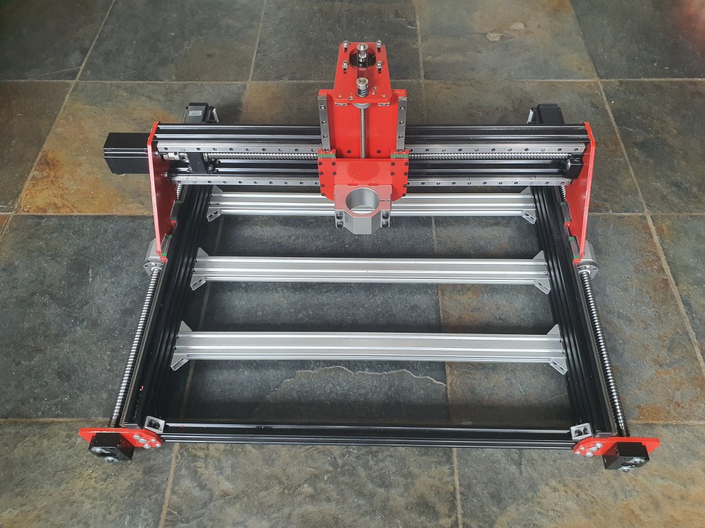
Plasma cutter router DIY ‘the simple way’

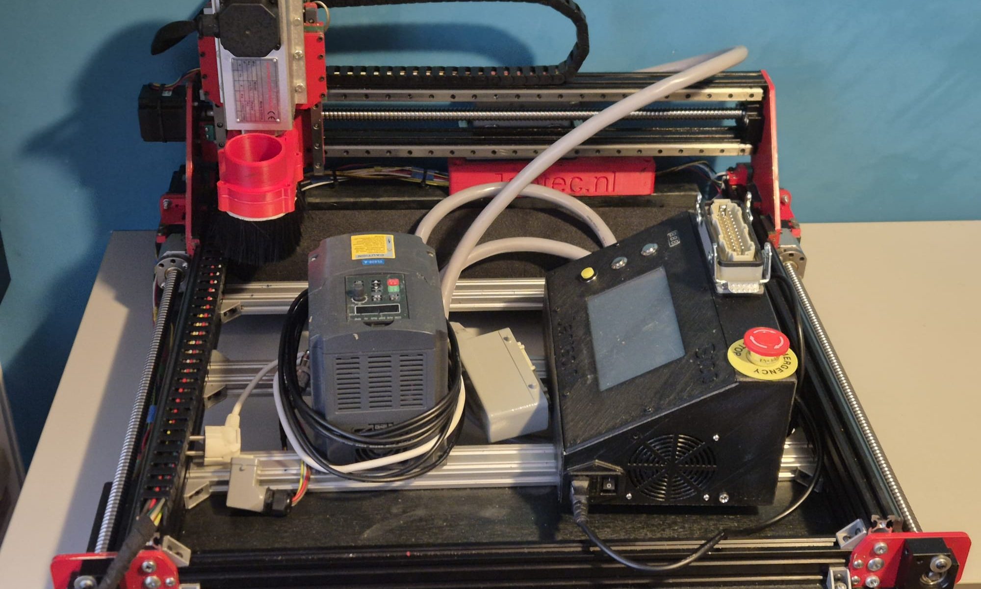
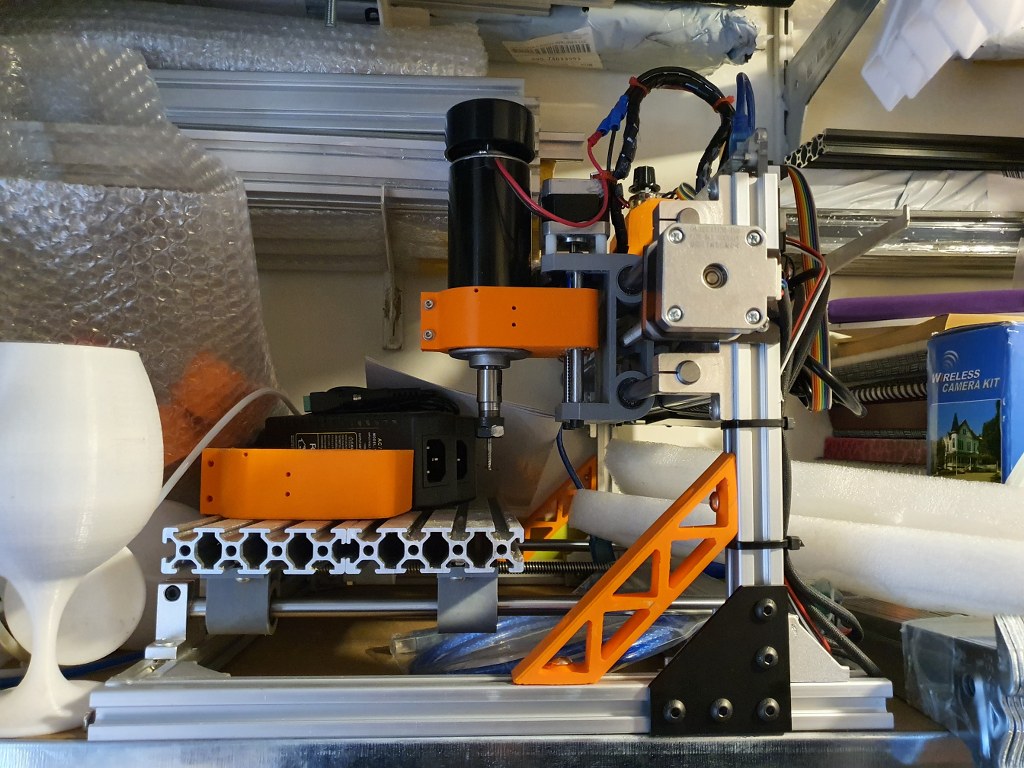
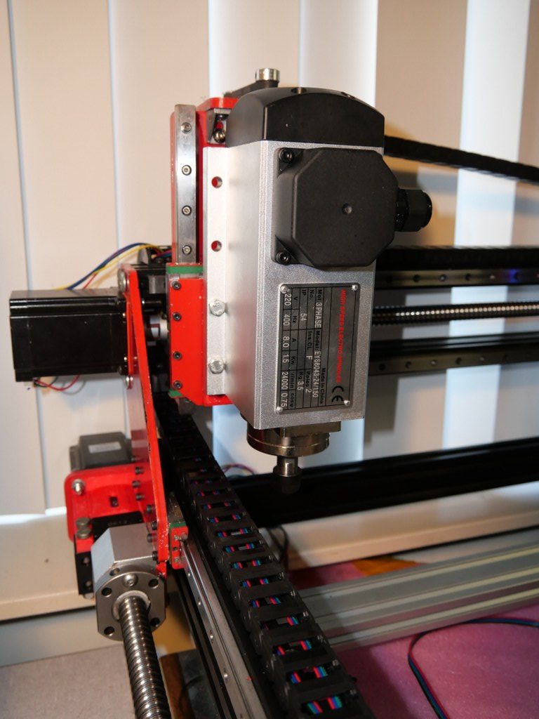
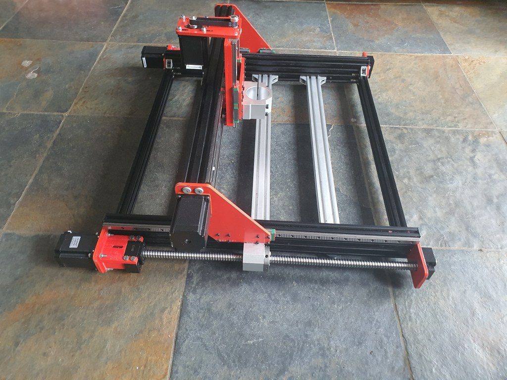
I am in the process of developing a router for my plasma cutter, since the cutter works very good but it will be way more effective once I can machine my designs with a router for this cutter.

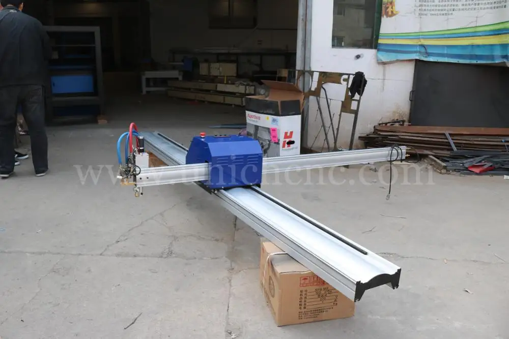
Example of a very big X-Y design for a Plasma Router on Aliexpress

My design differs from others because i will use only existing affordable parts that require no additional machining.

Firstly, you would need a cutting table with a maze where you can put your steel on, when cutting.  This maze will be enclosed with a steel box so no cutting debree will be thrown around.  Around the box a set of aluminium or steel profiles will be mounted on which the wheels for the X or Y axis will be built. From here on, a normal router setup can be made.

The plasma head will need to be adjustable in height but does not neccessarily need to be CNC movable.  Just a manual knob to move it up and down a little will do.

So, only 2 axis are to be made with CNC.

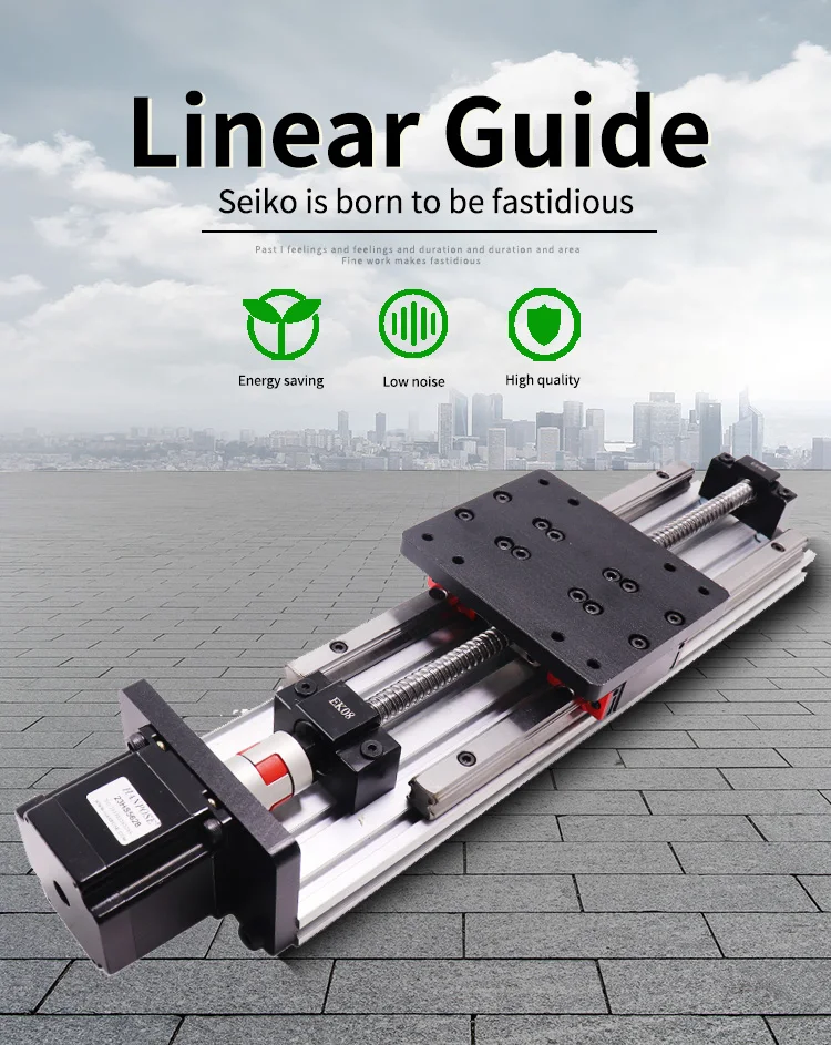
For the Y axis I will use a complete accessory from AliExpress with ball bearing 1604 and an effective way of 600mm, including  a Nema23 stepper motor.

Y-axis 1204 ball bearing screw drive, NEMA23 stepper motor and dual linear rails.  This will move the plasma head left and right.  I might use something a bit simpler that this…
HPV8-2
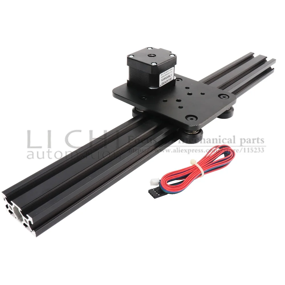
X-axis on both sides of the box that will move simultaneously forward/backward with steppers mounted in series, the Y axis will be mounted in between.

The plasma cutter ‘head’ will get a fixed (but a bit vertical movable) mount on the mounting plate of the Y-axis.

Magnetic Breakaway CNC Plasma Torch Holder
Magnetic break-away torch mount
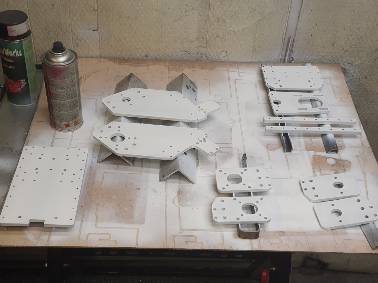
And the mount for the head of the plasma cutter

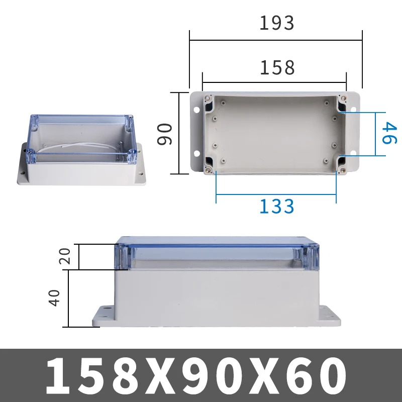
The electronics will be added at the front of the Y-axis in a 3d-printable box. (or you can buy a ready-made box HERE).

Electronics will be an Arduino UNO with standard GRBL shield, or THIS as a better all-in one solution, including local router managing.  At the beginning and end of each axis, a limit switch will be mounted.  Switches, cabling and mounts are available on Aliexpress  HERE and HERE.

Firmware for the Arduino comes from the widely available GitHub and the GRBL community.  GRBL software is available for Windows PC and MAC as well.  Designing can be done in any way, and the most simple way will be the online Cad solutions like Tinkercad .

Kid's Privacy Safe Harbor - BBB CARU

The power supply for the Plasmarouter will be a 24 Vols 8 Amps portable power supply like THIS one.

Indymill increased working space and stability Y-axis

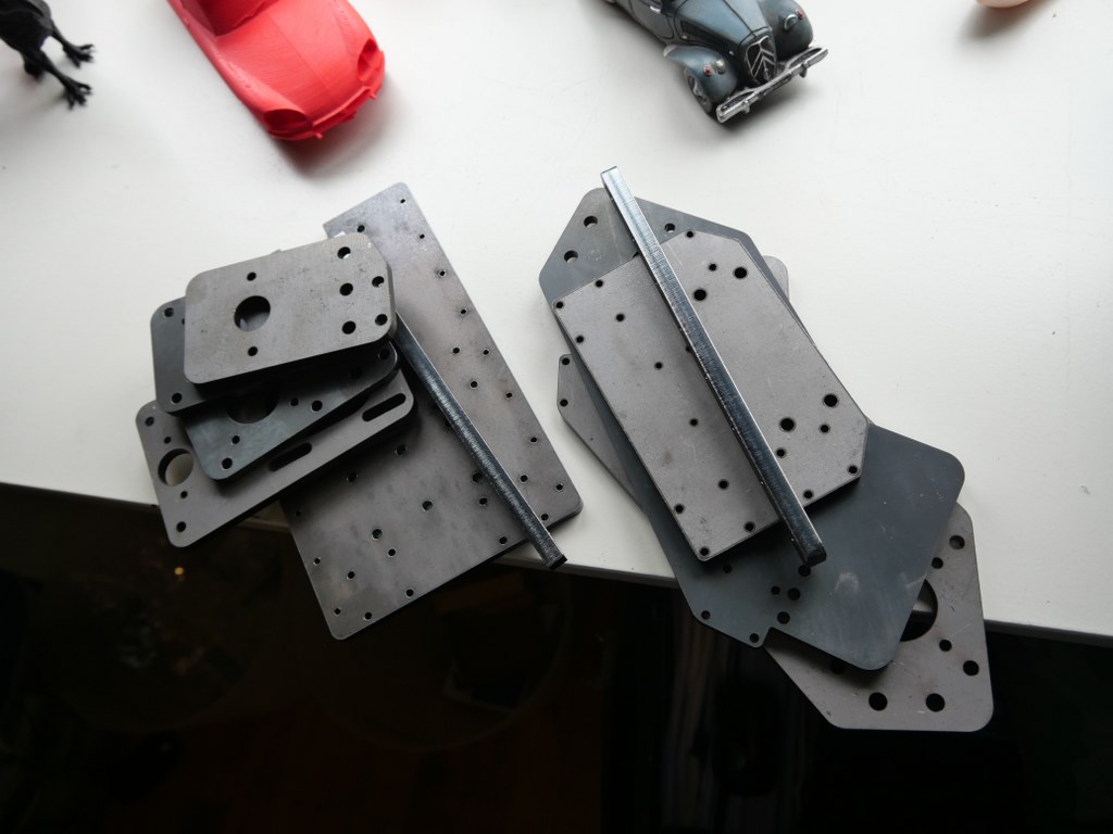
2021 05 13: Yesterday I received the iron plates for my Indymill from Nikodem Bartnik, and it was all very well packed and quickly delivered!

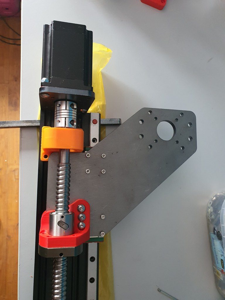
As I always do on any build, I first check the separated axis for best fit and possible improvements. I started with the Y-axis.  In the below picture, the left side of the macine is shown, being the left Y-axis.  The rest of the machine is not yet attached.

This is how I started with the original design. Ball bearing block (orange) and screw mount (red) are both 3dprinted here.

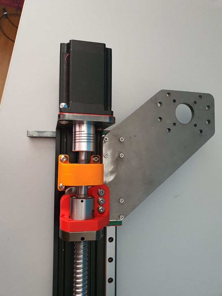
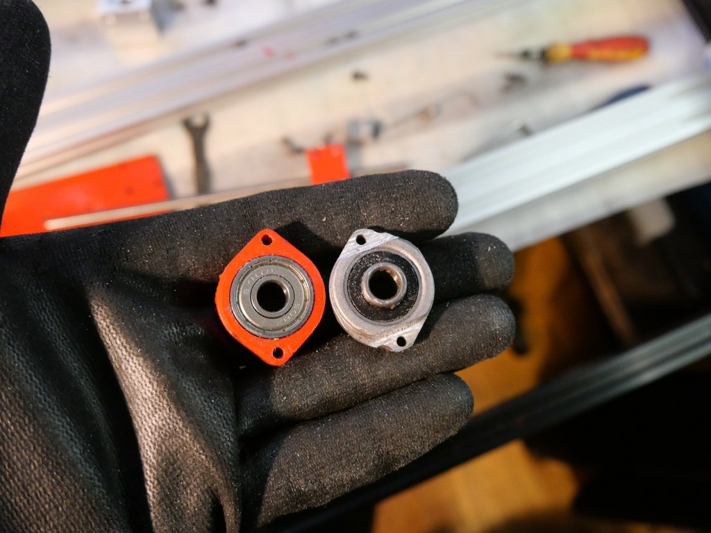
The Y-axis is somewhat limited in its drive towards the rear of the Indymill CNC machine, due to the bridge plate for the X-axis.  This bridge plate is blocked in its movement towards the rear because it hits the bearing block (orange part) that holds the ballscrew in place. By removing a small and unused part of the bridge plate, the movement can get about 6 cm extended towards the rear.  The pictures are attached to this post, please see how I made this.

Maximum movement towards the rear (top in the picture) due to a removed piece of the bridge plate

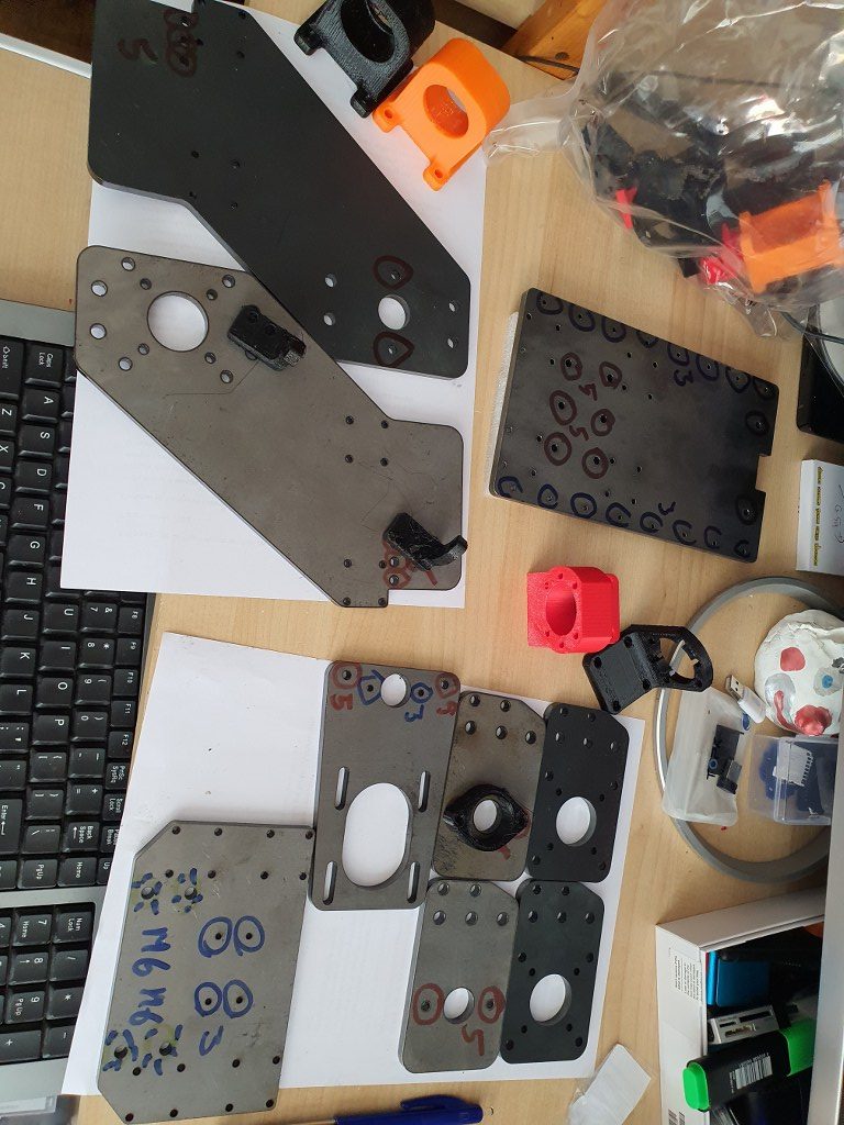
I used the plasma cutter to cut the parts out of the 6mm steel plates and after this was done, I used the lamel grinder to make it smooth.  Although I used a guiding rail for cutting, the power was apparantly a bit too much so it is not a very beautiful cut… -)  No worries because all still fits very well.

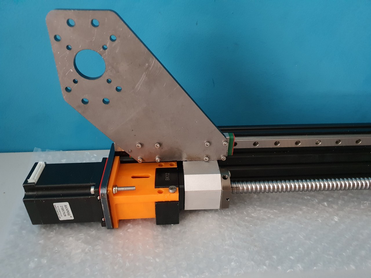
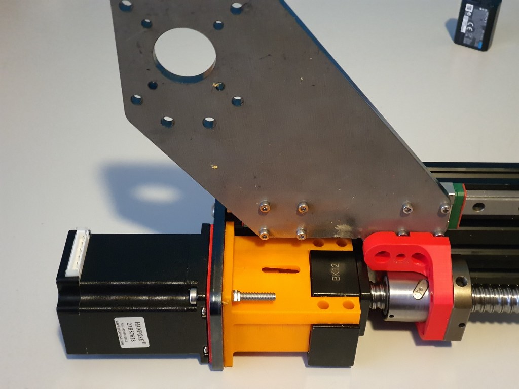
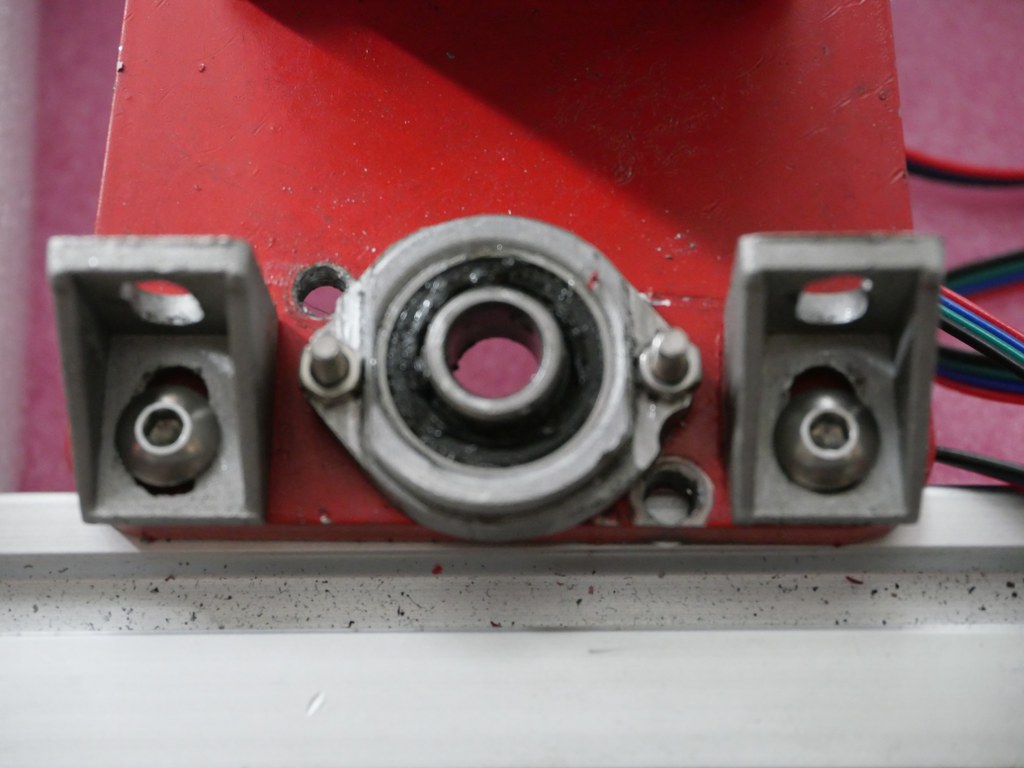
BK12 original axial bearing (black) for 1605 ballscrew and -nut (red) with Nema23 holder (orange) with an attachment for the original BK12 bearing, both placed on the left Y- axis of the IndyMill CNC
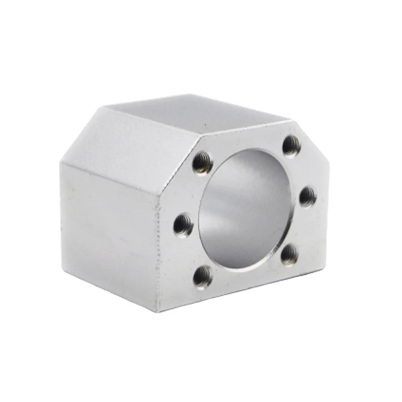
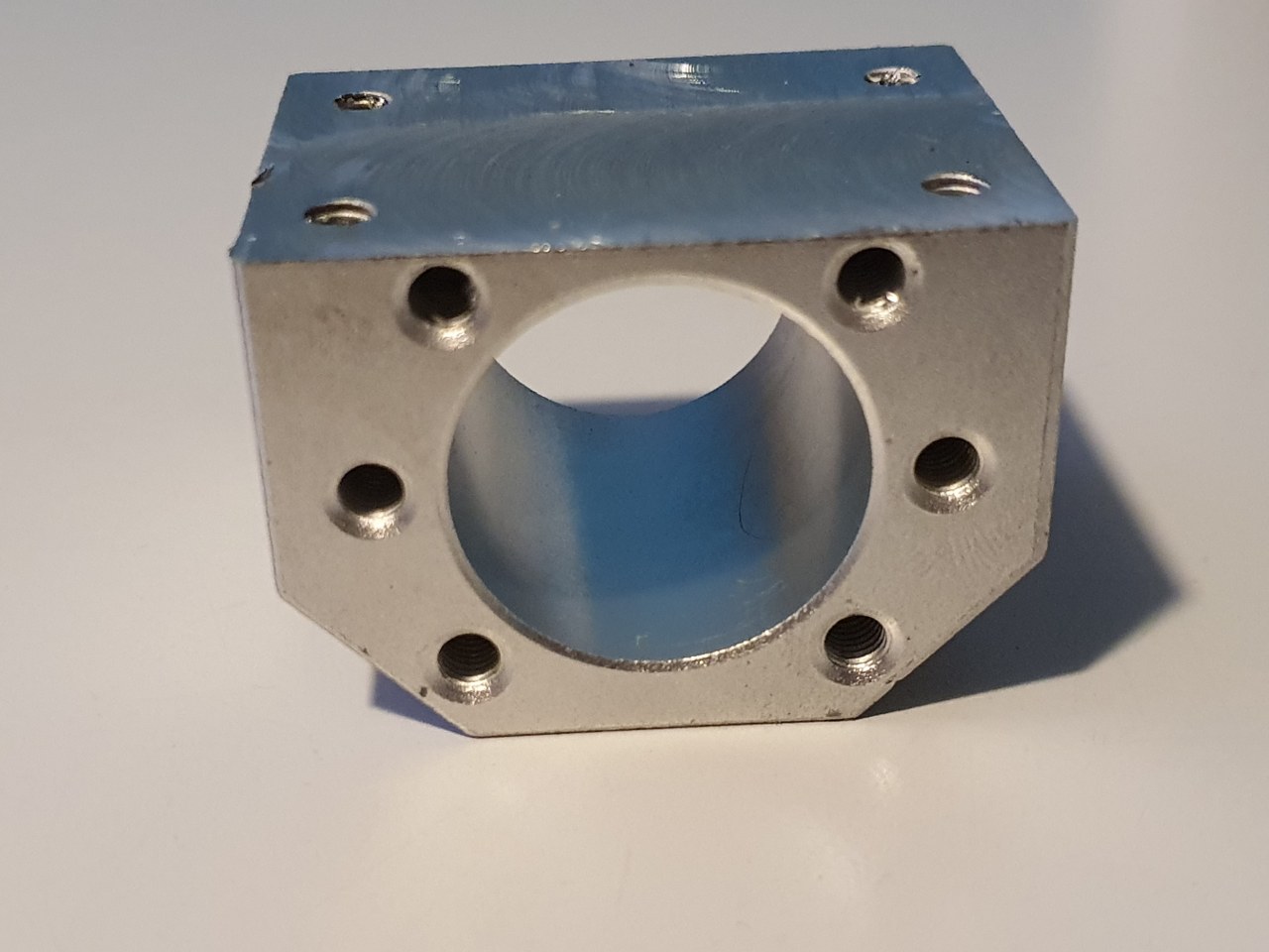
An original nut holder for a 1605 ball screw nut, machined down on my manual mill to fit the Indymill’s Y-axes
The nut holder in place on the left Y axis

FLY 407 Motherboard RRF3+ wifi + BTT 2.4 inch TFT + multi-extruder

2021-05-11

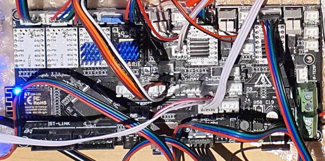
I got the Mellow Fly 407 board in today, and it now works awesome!

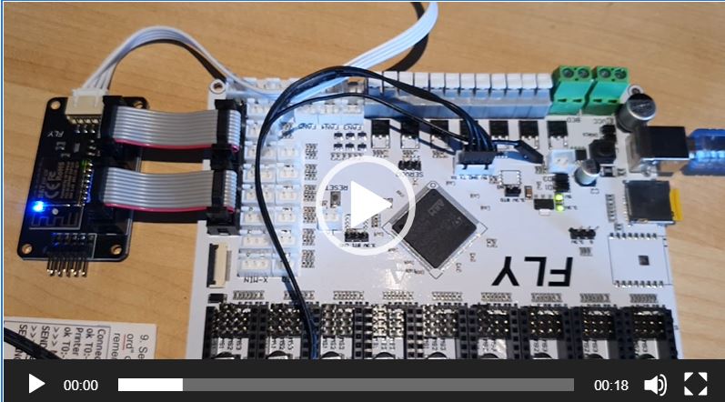
I hooked the Mellow dedicated wifi unit to EXP 1 and EXP2 and to the serial TFT connection, programmed the microSDcard offline on the PC with the files from the proposed Github site and it all went great!  (The little added user manual is very good, just follow the directions and it can’t go wrong!)

Burnt the board’s firmware first, then the firmware of the wifi esp module and after setting up the wifi with YAT via USB, I programmed the wifi settings.  Then, with the Duet’s WDC PC-remote console via wifi, I uploaded the FLY 407 motherboard with all the latest available firmware: RRF3.4 beta and the latest wifi- and DWC versions.

Then, I removed the serial connection between the TFT connection on the motherboard and the wifi module and plugged in the BTT 2.4 inch TFT at the same serial port.  Since there is only 1 tft port available, I use the same serial port as I used for programming the esp wifi module.  I already put the RRF3 firmware on the TFT unit.

Well, the results are awesome! On the TFT after connecting you see the extruder step from 0 to 1-2-3-4 and back to 0 so this all works very nice!

I must be honest here: I also tried the Mellow 7 inch screen but this is not yet really working as well to me as the little BTT screen IMHO.  The Fly screen is a lot bigger, though, and the Fly 7 inch TFT has great potential.  I know that it will also take some getting used to the FLY’s TFT screen layouts.  The access to the macro and gcode directory is nice, but since everything is placed differently than the PanelDue screens, it might just take some time to appreciate it more.

Geetech A30M first use

In mid-June 2020, I started using the Geeetech A30M desktop 3d printer.
The printer can print 2 colors mixed with 2 filament geared drive units on top of the frame and a fan for each feed to the combined hotend.

A few adjustments are needed on this printer if you really want to work well with it.
First of all, I had a lot of trouble with the standard noise from the 24 Volts fan under the bottom plate, which is supposed to provide cooling for the motherboard. This fan is always running at full power.
I put a controller in between with controls on the left side, through a drilled hole. I secured the controller with 2 tie-wraps through the cooling slots on the left side. The dial just comes through the case and you can hardly see it. Most motherboards I use don’t need a fan for cooling because they are placed freely in the open frame but the A30M has a closed case so a little air circulation is necessary. Plan is to add a thermostat control so the knob is no longer needed. Later. The controller is set to the position that there is a lot of air movement but without the whirring of the fan.

Second modification is the addition of a Geeetech 3d touch on the hotend. The bracket was included with the printer, suitable for both a thick inductive sensor and the 3d touch sensor. What’s nice is that the software (or firmware, if you will) as suitable from the factory for autoleveling. Do pay attention to the correct placement of the connectors, from the front view the brown and black wires should be mounted to the right.

The disadvantage is that the firmware from factory does not really work well with auto leveling. In the middle of the hotbed everything goes fine but with larger prints I noticed that the first layer was printed very differently, so everything kept coming loose. So now I work with manual leveling while automatic leveling is possible.

The hotbed is nice and big with a workable size of 320x320mm. The print height is 420mm.

The price was over 400 Euro, and the delivery was from Germany.

I recommend everyone to secure ALL and especially to include the block hook. My one was really not assembled properly. All threads were OK but all bolts were either too tight or not tight at all. I only found this out during the first test print. I stopped and checked everything. Pay special attention to the rollers of the hotbed. It is difficult to reach them but in my case the adjustment wheels were not set at all and did not rotate. The disadvantage of such a desktop printer is that you hardly have any space under the hotbed.
The vertical V-profiles were not mounted perpendicular to the upper profile. That is difficult to repair because everything is drilled through and bolted. I recommend installing corner stiffeners at the back in the top 2 corners. I have them on order and then they can go right on.

And… what some large printers have and the A30M does not: Additional stabilization rods to the front (or to the back, that is also possible) so that the vertical profiles cannot move. Now when you apply a little force there is about 2mm of play on it, despite the solid mounting to the desktop housing.

Voron 2.4 Core XY build

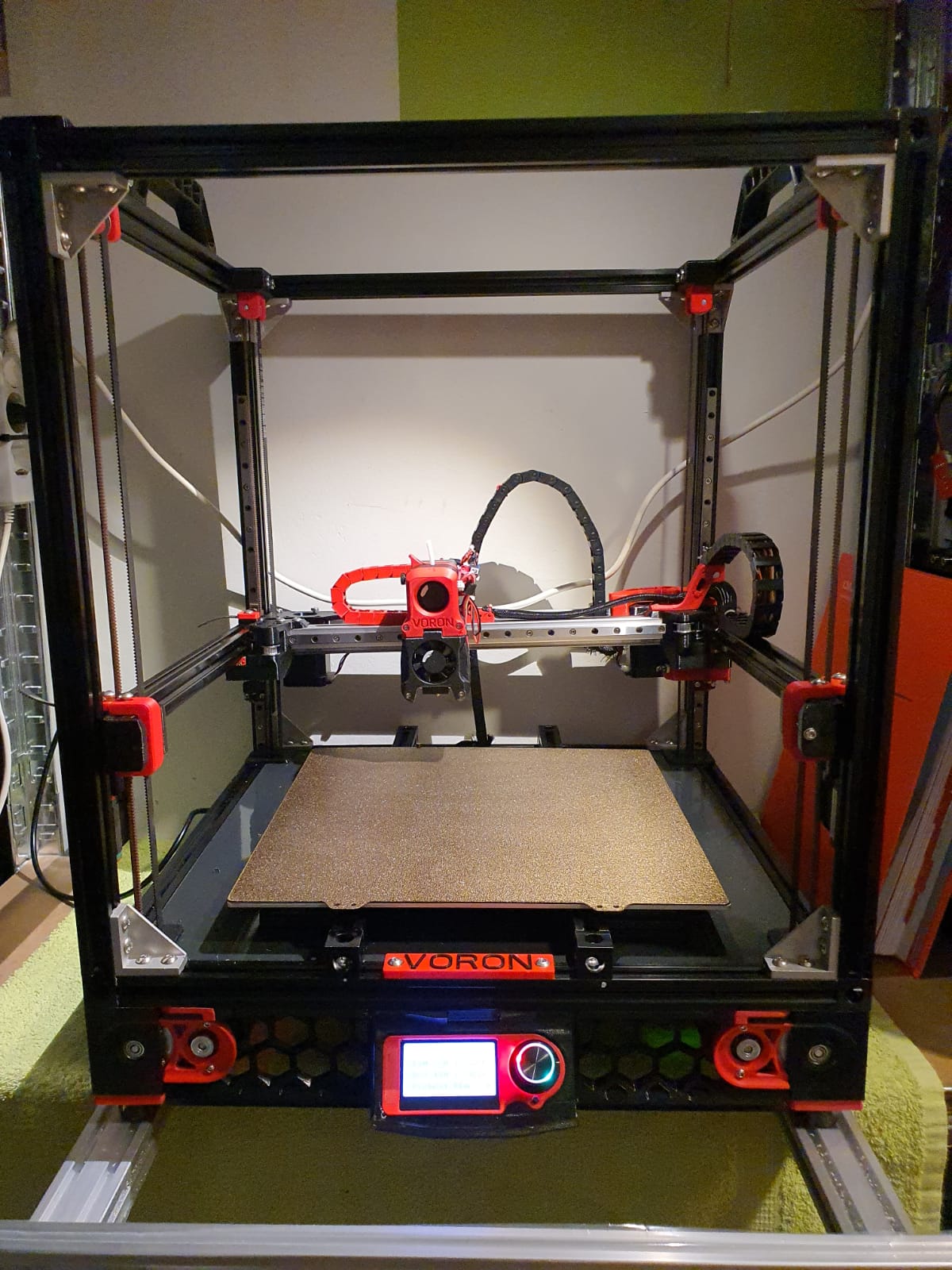
My experiences with CoreXY printers are excellent, so I chose a VORON for my home-built COREXY printer with a print size of 300x300x300 mm.

Developed from a large community, the VORON is one of the best and most reliable 3D printers.  And this printer just looks really good!

Via AliExpress, Banggood, Reichelt, aluminiumopmaat.nl and plexiglas.nl I ordered all the stuff, according to the bill of materials I could download from the VORON site.

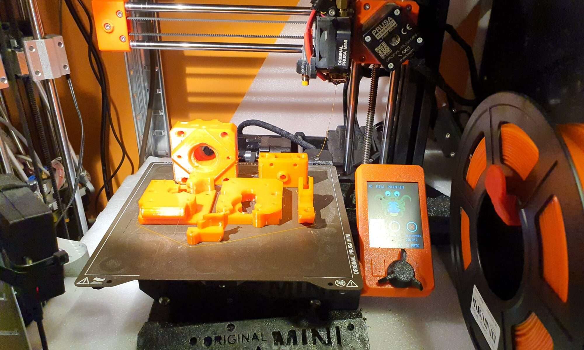
I printed the PETG parts on the Prusa mini at 0.15 fine.

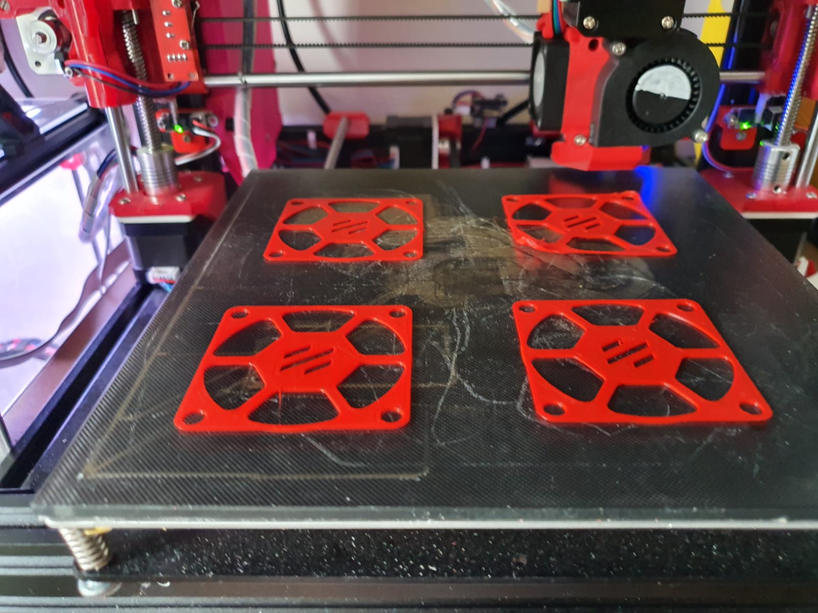
The ABS parts (red and black) were printed on the Twotrees Sapphire plus.  It took a lot of ‘tweeking’ before the ABS came out well but in the end I got a nice result!

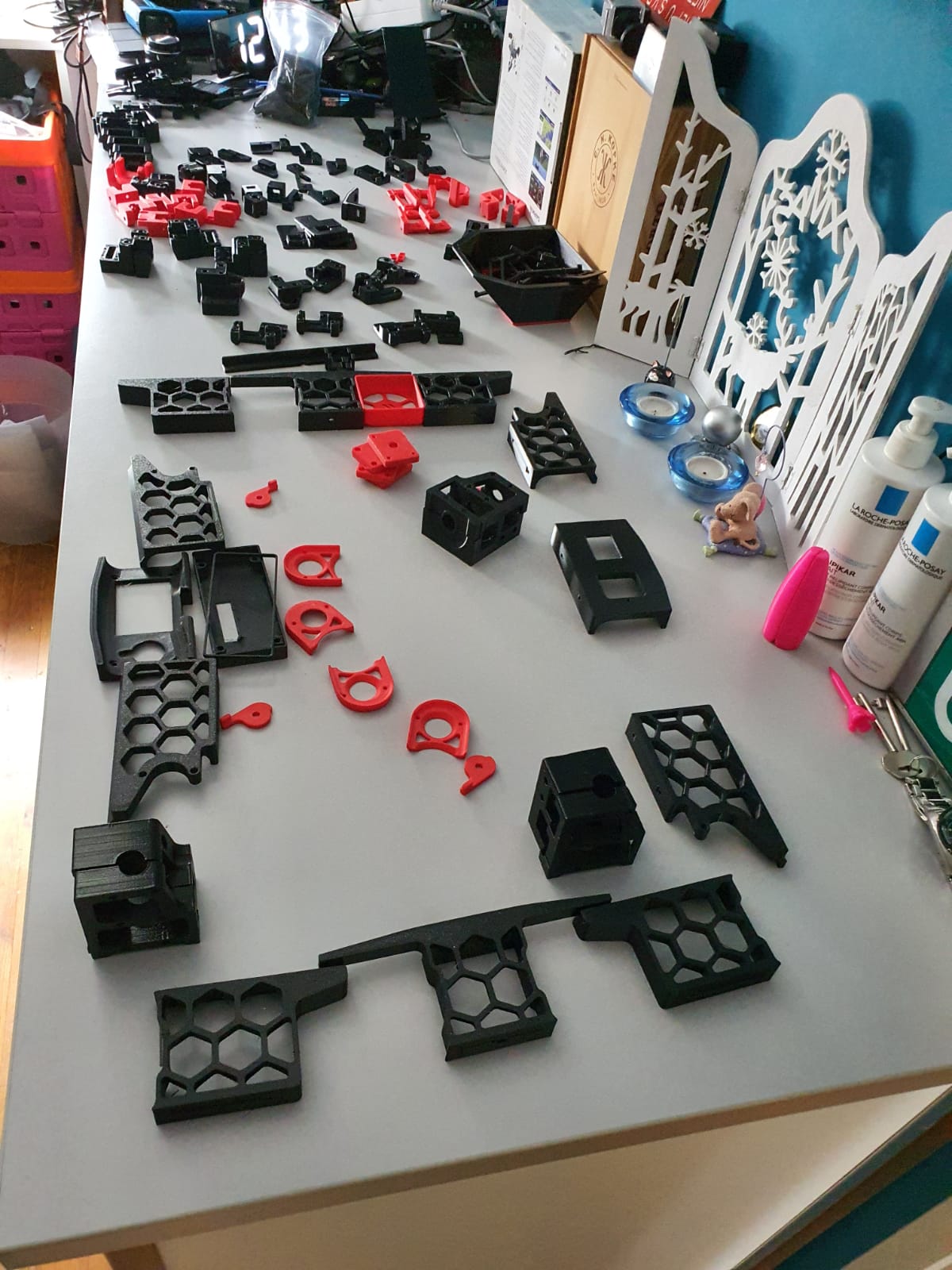
Printed parts for the Voron 2.4 300In the end, rebuilding is not really self-building and it is more based on ordering and assembling than getting to work with the saw and drill yourself.  Also the necessary 8(!) linear rails of 350mm, bearings, gears, belts, motors, electronics and so on have been ordered and the rest of the necessary stuff has been printed (25-8-2020).

For the control part I have chosen one PI Raspberry PI 4B 4GB and two pieces of SKR 1.4 turbo motherboards, according to the VORON recommendation.

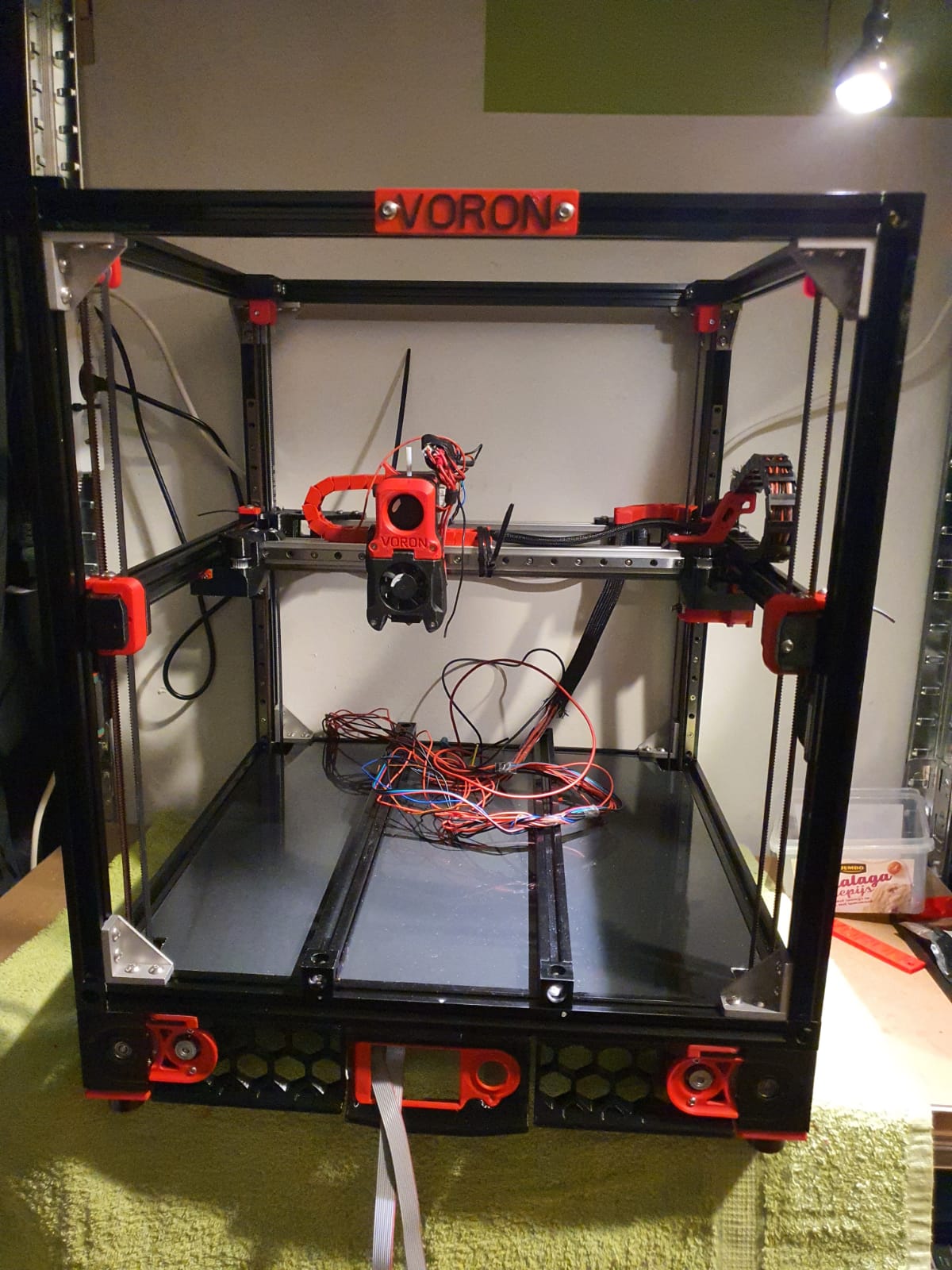
Building the Voron 2.4 with the afterburner Beta1 hotend combination is illustrated by the following pictures.

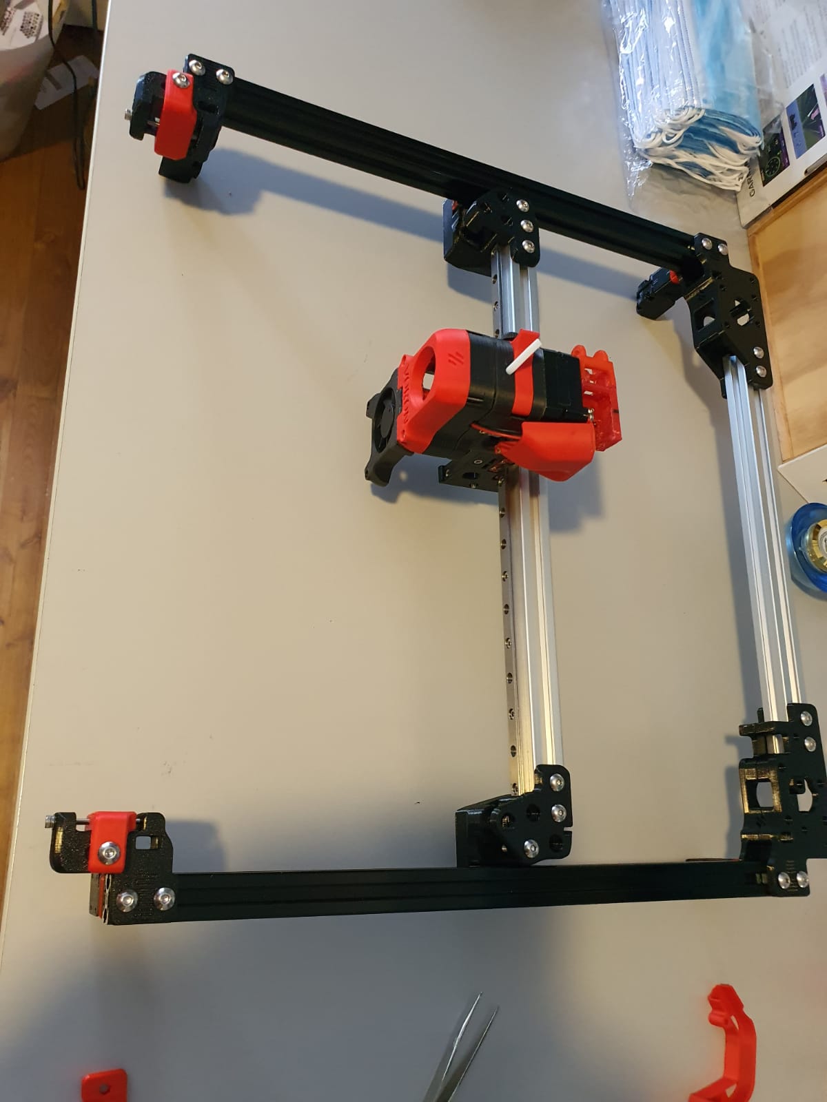
Gantry ready:

Gantry of my Voron 2.4 300Housing and skirts underside with Z-motors yet without the gantry mounted:

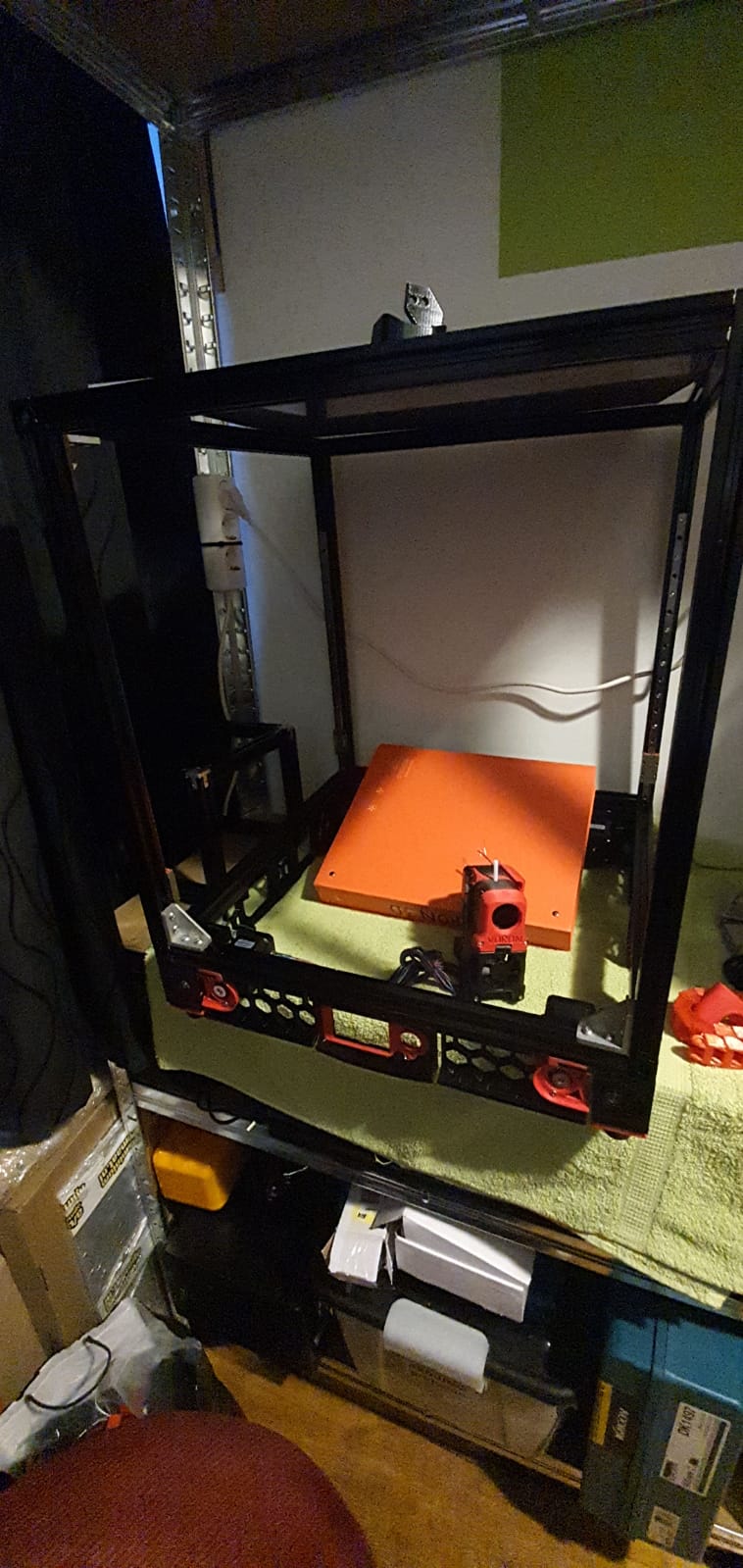
Frame of my Voron 2.4 300
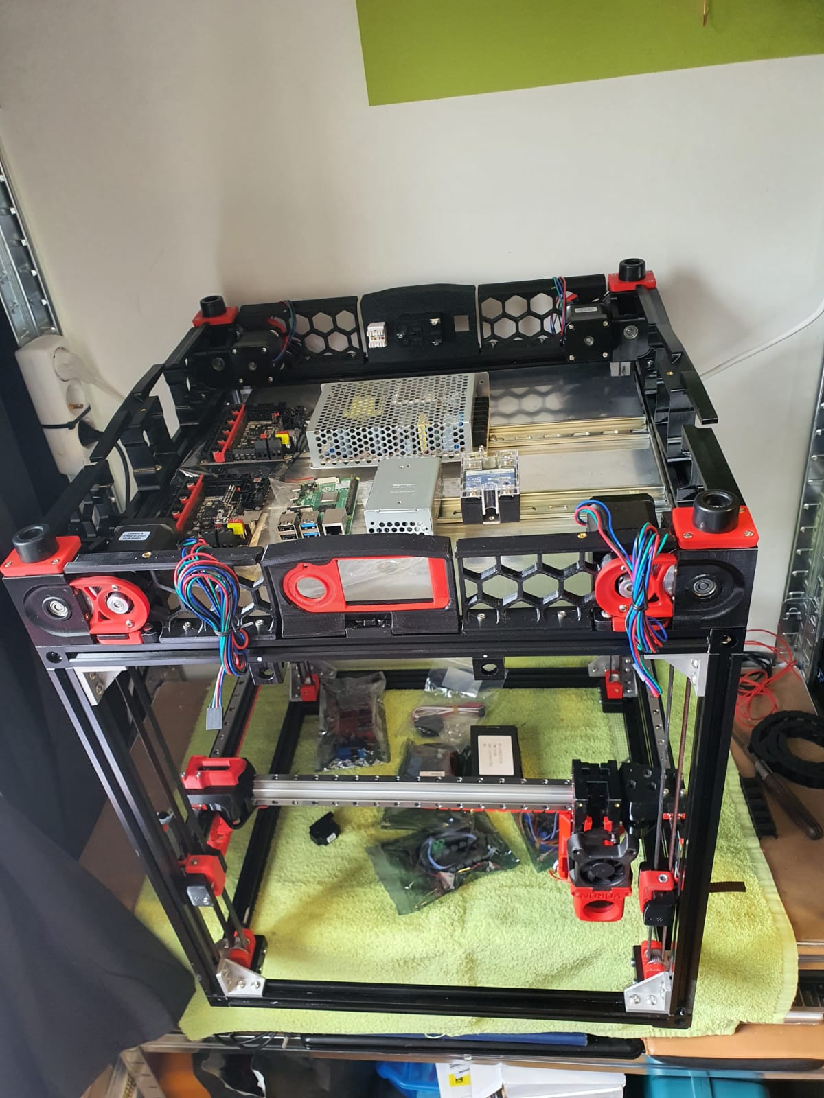
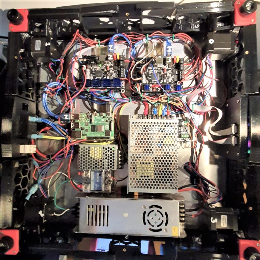
Electronics positioning underneath my Voron 2.4 300

Below: The 9 mm drive belts of the 4 Z-axes placed:

Halfway the building phase of my Voron 2.4 300

And the assembled base plate with the rails and controls, power supplies and so on (printer turned over):

Cabling and electronics of my Voron 2.4 3000: 2xSKR1.4 turbo with Klipper, Raspberry PI and Octoprint with Klipper

We are still waiting for the bearings for the Alpha and Beta drives in the gantry.  These bearings are used to make a tension roller per 2 pieces.  I had originally bought idler bearings for this purpose, but the diameter of the collar of these bearings is just too large.

Too bad but then I have to work on the Raspberry PI4B in combination with 2 times SKR V1.4 turbo motherboards.  The PI will make a new config.bin via Klipper for the SKR V1.4 motherboards so the PI can drive both SKR boards at the same time.  On the main board will be Alpha and Beta and the extruder plus the extruder heater, on the other (Z) board the 4 Z-motors and bed heater.  By itself a Duet with expansion board could have been an option too, but the Voron designers made it with the PI, Klipper and 2 SKR boards.  And I try to stay as close to the design as possible . -)

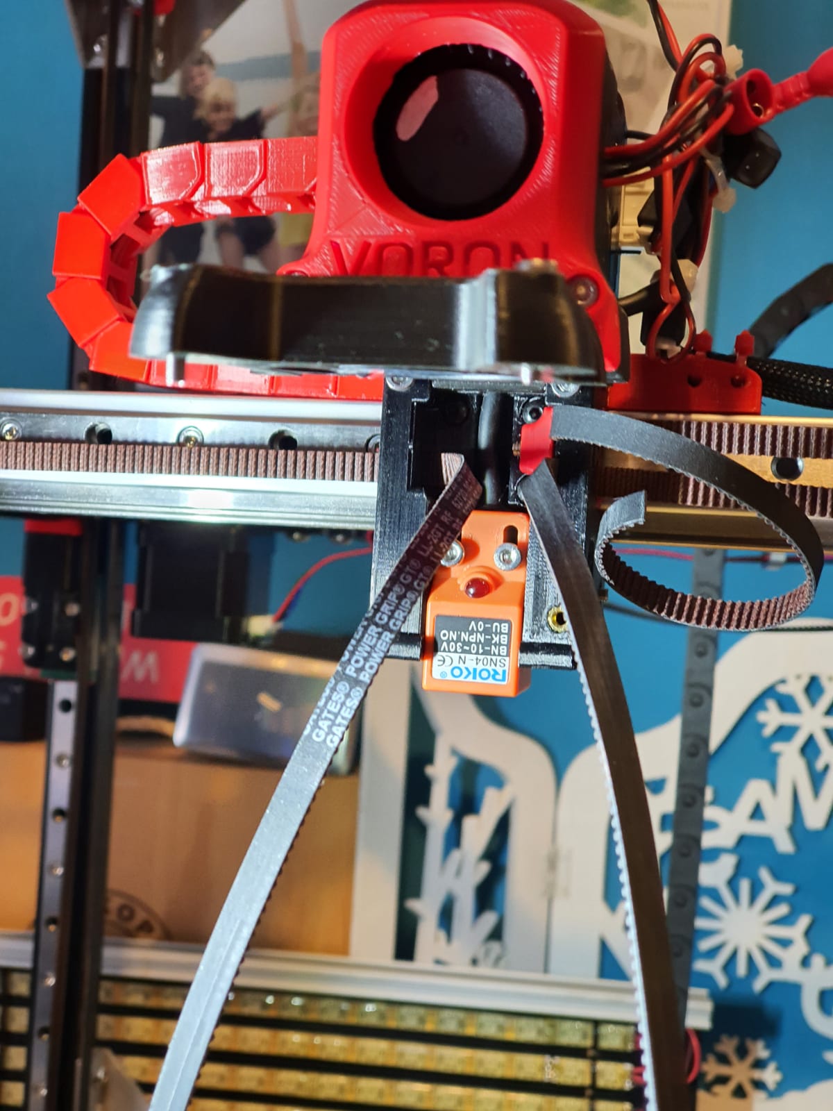
Below: Threading the straps, no picture used.  Just start somewhere and you’ll end up right.  Oh yes, also changed the sensor in the config from NC to NO..

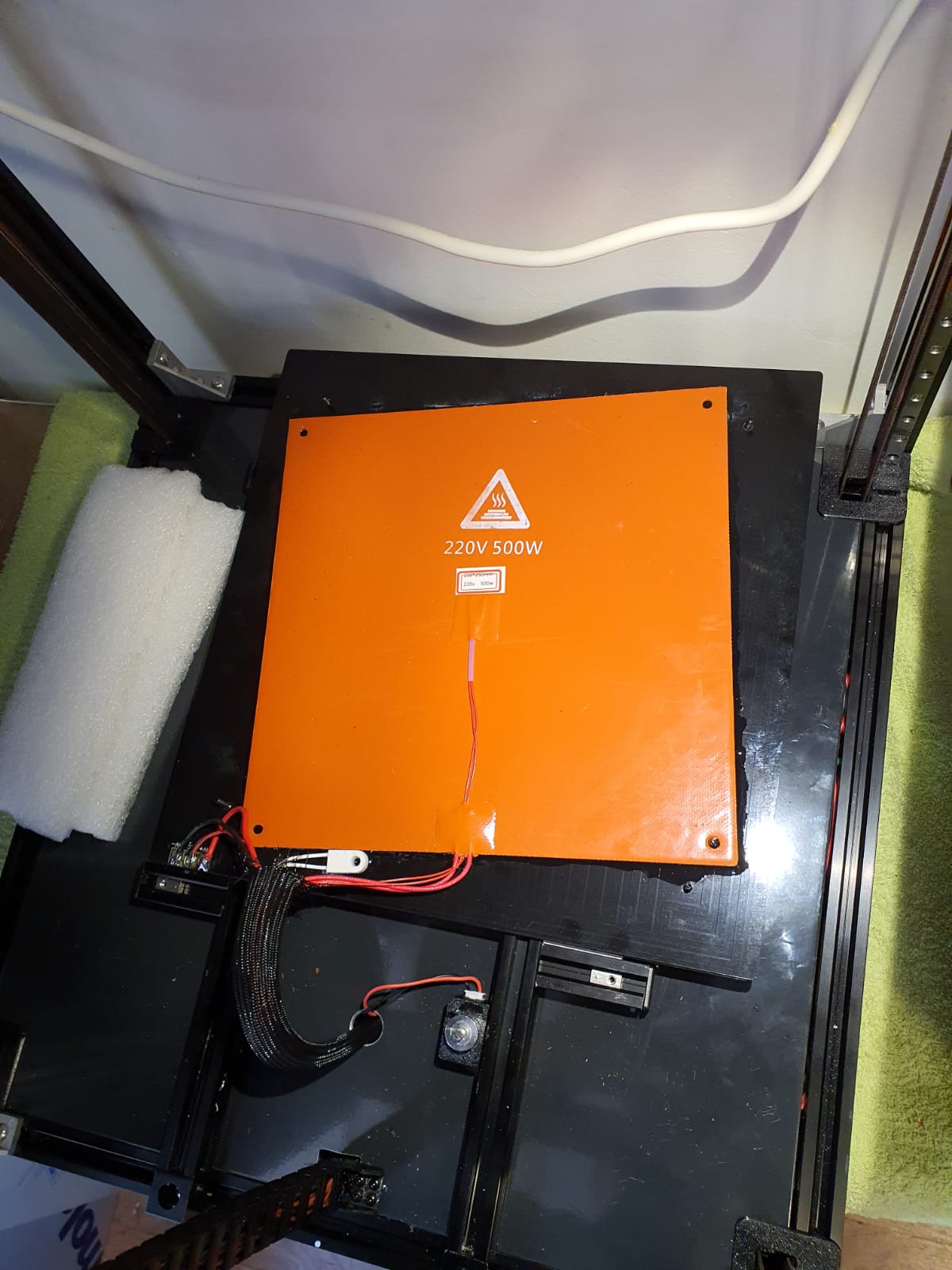
Below: In addition to the 24Volt 200 Watt hotbed nevertheless also added the 500 Watt 230V.  With only the 24V version it took more than 20 minutes to get to 110 degrees Celsius…

Old:

And new— no PID run done yet..)

Below: The steel plate is placed on the sticky magnet sheet.

Below: First print….  I had to search for the Z offset adjustment and the extruder turned the wrong way around.  Also the gantry leveling took some thought, you actually have to make the basic setting with a ruler, otherwise the leveling takes a long time.  Nice is that a bed mesh leveling is not necessary anymore, but of course it can be done.  You turn a home and because the nozzle always calibrates the Z on the mechanical Z endstop, and the gantry does all the leveling, you always have a good first layer.  Unless the bed warps but with such a thick plate that seems almost impossible. Just to be sure, I did include a bed_mesh profile in the config.g.  By the way I just used a 24 V aluminum hotbed as a base because my 8 mm 310×310 plate turned out to be a cut plate instead of sawn.   And a cut sheet turns out to be non-flat on the cut sides by default, unfortunately.  Flattening costs more than a new plate, maybe that will come sometime….

And with enclosure, camera and the TOP LED’s:

Afterword:

In practice, I fixed a few more minor flaws, including:

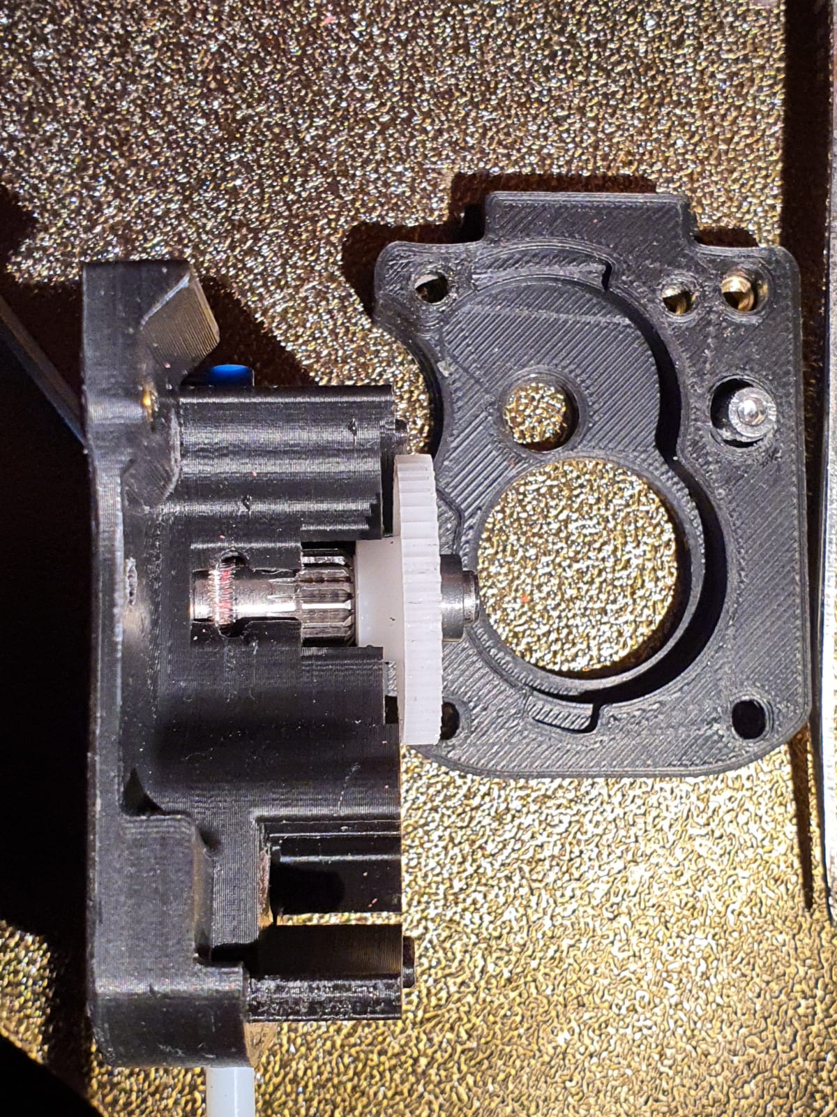
Extruder tuning.  The donor extruder turned out not to pick up the filament properly.
First I tried to put a ring in between the left side of the shaft, but then the nylon gear on the right side of the shaft gets tight and the housing can’t be closed completely anymore….
I ended up using a spare set of dual drive extruder gears and swapping the set of gears.  With that, the filament was properly aligned with the running path of the gears.  See the picture how it was at first:

Misaligned filament path in Afterburner extruder

Hotend tuning
After the PID runs of hotend and heated bed, my chosen assembly of the custom ED6 heater block, the heatbreak pipe and the cooling element turned out not to fit together properly.  The result was that when the filament was extracted, a thick piece was always stuck at the end.  This was caused by the heatbreak pipe not fitting tightly on the nozzle.  There should be no play between them.  I completely demounted the filament and screwed the heatbreak pipe 2 turns less into the cooling element with red threadlocker.  Let it harden for a day and then I assembled the rest.  By the way, I also mounted the teflon version of the heatbreak pipe in stead of the titanium version.  The tintanium version was to my experience a bit too stiff.  Or my filament was too old or inferior.  In any case, after the modification, everything works without problems.

Hotbed, TPU and ABS
To print TPU and ABS without brim or skirt without warping I bought a magnetic PEI steel plate with coarse profile.  It really works perfectly. Both ABS at 110 degrees sticks nicely and TPU at room temperature sticks nicely too.  And the removal is also without problems.  Occasionally I spray a little hairspray on the plate but I don’t think that lacquer is really necessary at all.  It is meant to make the removal easier.

Tension of the belts
I tried getting the belts at the same tension, this was not that easy.  Finally I ended up with a mechanical way of measuring tension after putting 1 at my desired tension and comparing this as reference with the other to be compared belts.  So, for the Alpha and Beta belts I first did a ‘good feeling’ setting and then I used my old trunk scale weight device to measure the tension when pulling the belt A. Then, I used the device to measure at the same place for B. And I repeated this for the 4 vertical belts.

Alignment
Aligning the machine is also a bit of a challenge…
You must assume that your frame is square and straight.  You have to check this thoroughly.  Both vertically, horizontally and diagonally.  Then you can adjust the gantry. Loosen and remove the A and B belts.  Or do the alignment BEFORE placing the belts.
Fix the horizontal position of the Gantry otherwise you can’t align at all. Place 4 equal distance blocks of about 10-15 cm under the sliders of the vertical linear rails on the lower 2020 profiles, in the 4 corners through which the gantry rests stably. I have placed position holders under all MGN9 vertical linear rails afterwards so that the rails cannot slide in the 20×20 V profile.  If you use ‘regular’ 20×20 extrusion profile you don’t have a problem because there is enough ‘meat’ left for attaching your rail to the profile.  With V-profile, the groove is a bit wider and it is very difficult to mount the rails neatly without tools in the groove.  My frame is of V-rail profile and the gantry of plain 2020 profile.
The alignment of the gantry I started at the back.  Loosening all screws a bit, including the screws of the convex connectors that hold the gantry to the linear rails.  By the way, I see some builders placing these screws with multiple spring washers.  I’m going to do that too…
At the rear of the gantry, push the gantry completely against the rear.  There should be no gap between the XY joints and the frame.  PS: Leave the endstops off for a while at this action!
While the gantry is sitting against the back, tighten the XY joints and the sliders of the X-axle as well. (the side of the endstops holder is temporarily secured with 2 screws)
Tighten the rear 2 gantry joints (with the convex surfaces) as well.  This fixes the rear position at right angles.
Carefully slide the gantry forward. This should be possible without any effort.  If not, check whether there is enough play (and if necessary loosen the screws) on the gantry joints at the front (with the convex surfaces).  If you still don’t have a free run to the front, your frame is not good or your vertical rails are not seated properly.  First check the correct positioning of your rails with your position tool (from the printed stock) and to be sure also unscrew the 4 screws on both front vertical rails.  Try again if the sliding of the gantry goes smoothly.  Still no good?  Then reverse the procedure and start at the front.  Try to set the gantry exactly level with the frame.
After adjusting: Test the alignment also halfway (vertically) and at the top!

Wobbling in cheap linear bearing screws

As I experienced, from my 10+ 3d printers only the Prusa mini and the I3 Bear deliver adequate print quality.  Even the Voron 2.4 CoreXY has problems if you look carefully at the printed results.  Though all prerequisites were made to build a good printer, it was never really matching real good quality.  So- in my search for the root cause of this somewhat disappointing discovery, I stumbled on some interesting stuff: The HevORT Advanced DIY 3D Printer project.

I found this website as a link from one of my fact finding searches for the cause of wobble in my linear rails that I am using for my Indymill CNC.

Obviously, the cheaper rolled linear screws with ball bearing nuts are not as good as the ones that are first cut on a lathe and are then grinded on a special machine.  The better linear screws with ball bearings are specified into 10 categories from 1 to 10 where no.1 is most expensive and no.10 the least expensive. Quality is better with higher price.  Prices are over 500 Dollars US for the better ones, but can mount up even higher.

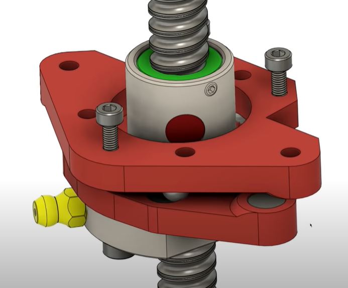
If you look at the category of the rolled ball bearing screws, these take a lot of strain in the material due to the manufacturing process. The strain causes an unequal surface and therefore this can cause lateral wobble.  When using these cheap linear ball bearing screws for 3d printers as Z-drives, the lateral problem can be solved by adding shifting plates as horizontal shift compensator.

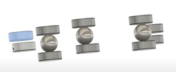
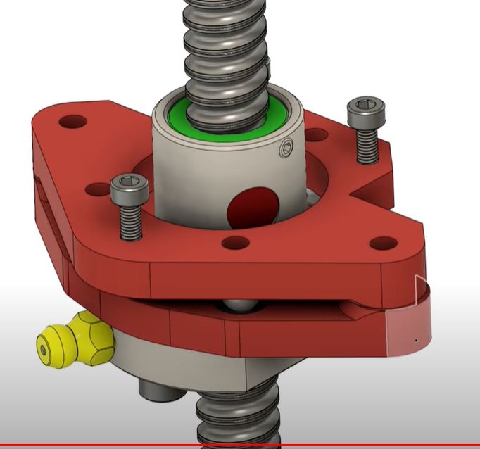
On the net, a solution is given by using a couple of bearing balls (3) between magnets that are used as rolling plates on top and bottom.  The shifting plate holders on top and bottom stay aligned with each other by mounting 2 magnets that attract each other on 2 sides of these plates.  Please see the cutouts I took from the movie that is provided in the above mentioned link:

This can be implemented in the HevOrt BUT I feel that my Voron2.4 could really benefit also from this solution. Although the Voron is depending on the vertical linear rails for sliding up and down and a belt mechanism is making the motion happen, the mechanism that compensates for any wobble or different sizing of the frame is only a friction plate of (in my case) 2 PETG surfaces that slides on each other, 1 per vertical axle.

So, I will see what I can find or make to get the above anti-lateral wobble solution built and implemented in the Voron 2.4 asap and see what the result will be!


Amsterdam

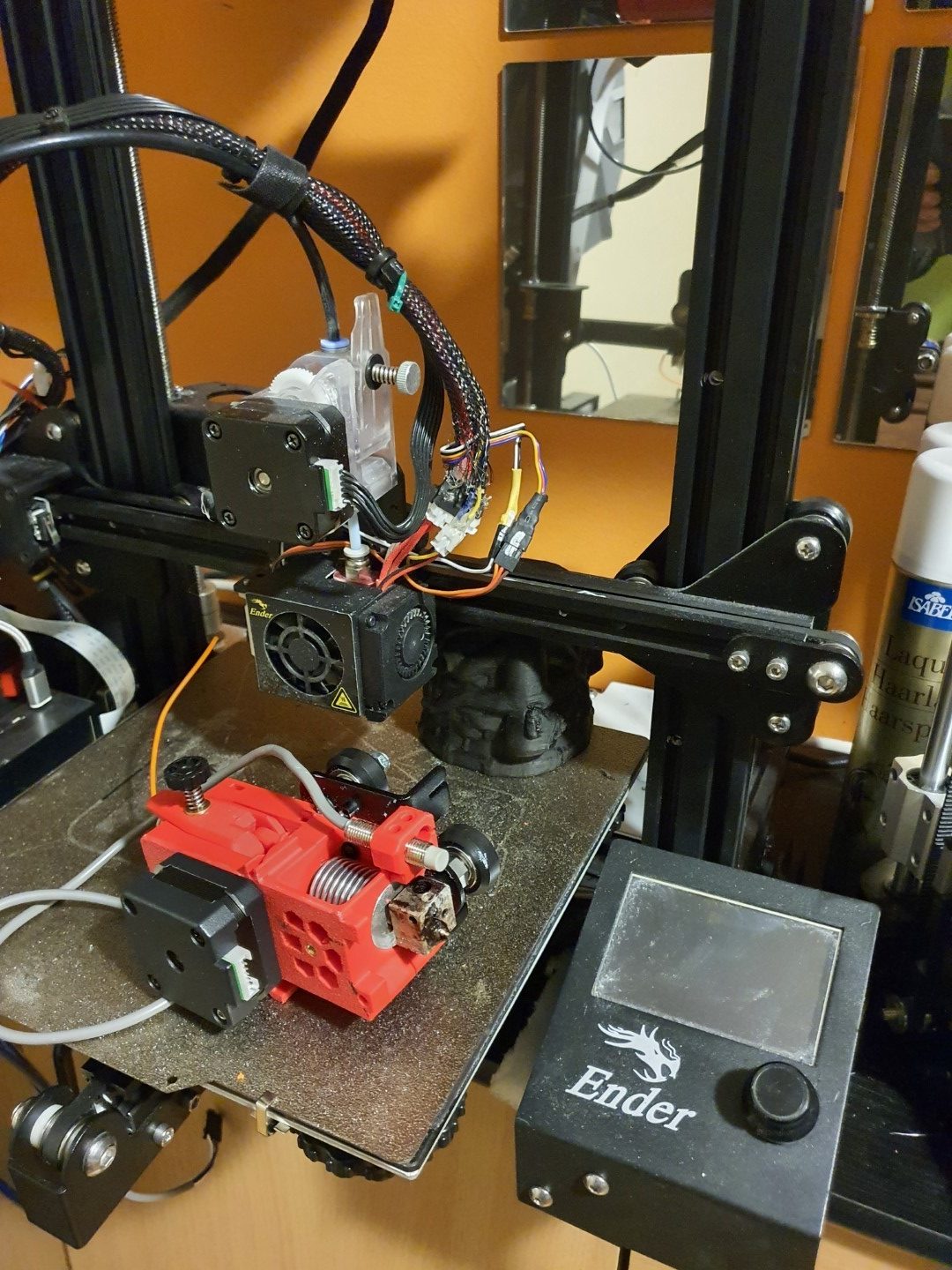
MMU2S on Ender3pro with TT SKR E3 mini motherboard

In 2020 I upgraded my Ender 3 with synchronised Z-axes and a new motherboard, the SKR Mini E3 V2.1.

The Ender 3 is very reliable and has been equipped with a direct drive bondtech extruder but still has the original hotend.

I chose the Ender3 to be the 3d printer on which I will attach the MMU2S.  This also means that I will have to exchange the hotend/extruder combination with a Prusa Mk3S version.

Started this on May 4th, 2021.  Only the printed parts were needed, all other parts were already available through sourcing form a.o. Ali.  I printed everything in ABS, mostly red.  For this I used 2 machines: The Twotrees Sapphire pro with enclosure for black ABS and the Voron 2.3 (300) for red ABS.

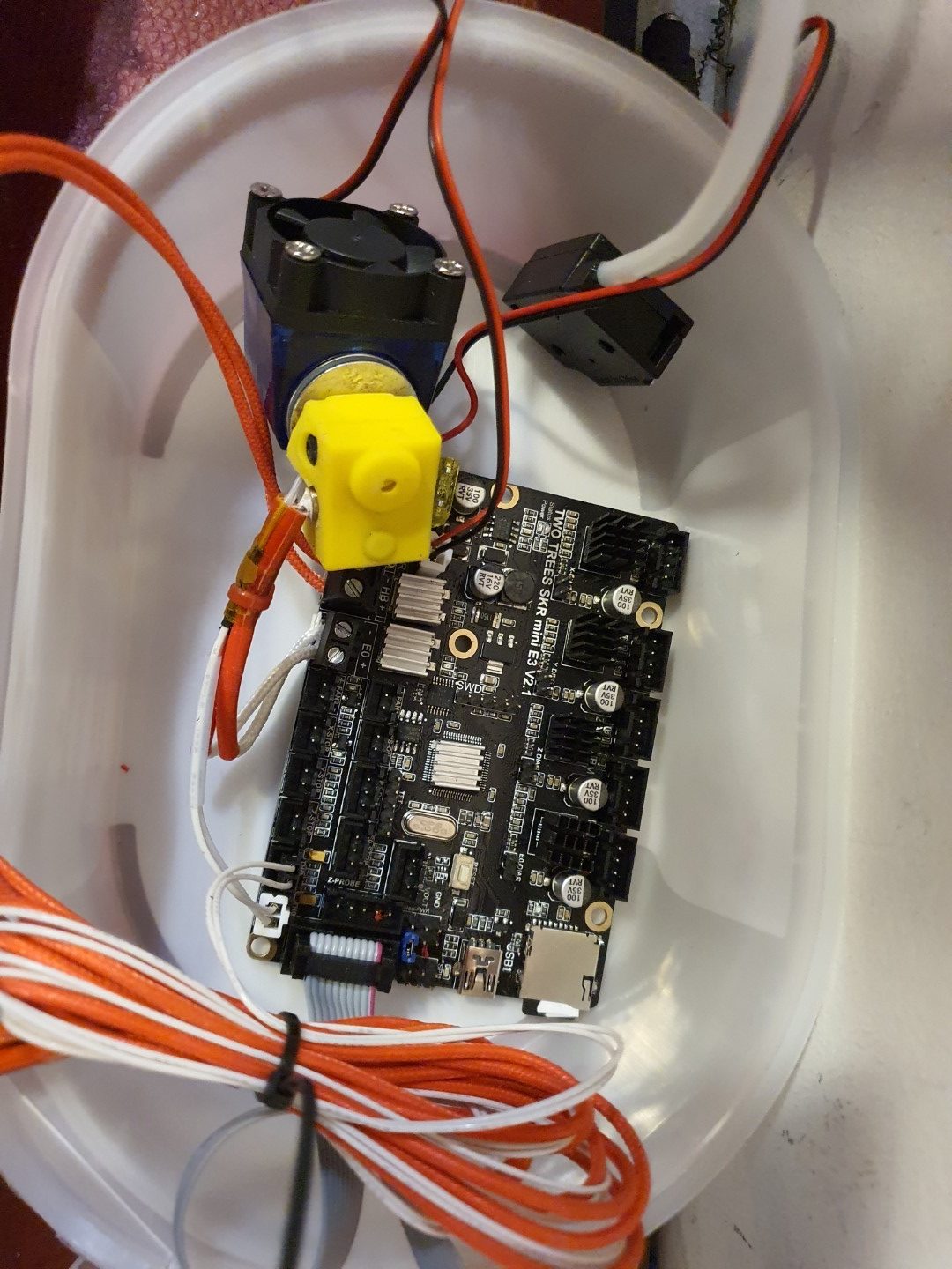
The motherboard that is also in the Ender3, SKR mini E3 V2.1.  I used this setup to test the MMU hard- and software together with the SKR mini E3 motherboard
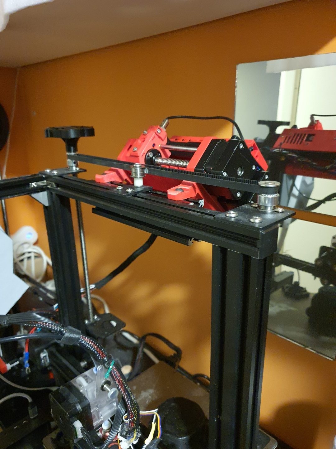
The MMU2S on top of the Ender3, just next to the 6mm belt that connects both Z-leadscrews
The bondtech Prusa MK3S hotend/extruder combination, mounted on a 2020 mounting plate for the Ender3

There is a firmware version for the SKR mini E3 V2.1 on Github that makes use of the MMU2S.  I downloaded this version and uploaded it to the board via visual studio code maker, all works well in the test setup. Some tweaking was needed in configuration.h and in the advance config, since I am using the S-version of the MMU2 and the filament sensor was not standard ON. And- it appears that the communication port needs to change to the 2nd port. You can see it all at the Reddit page, the additional changes to the published config files are these (thnx to fixel112):

Excerpt from Configuration.h:

#define SERIAL_PORT -1

#define SERIAL_PORT_2 2 <————— This has been the issue. Uncomment that line.

#define BAUDRATE 250000

Excerpt: Configuration_adv.h

#if ENABLED(PRUSA_MMU2)

// Serial port used for communication with MMU2.

// For AVR enable the UART port used for the MMU. (e.g., mmuSerial)

// For 32-bit boards check your HAL for available serial ports. (e.g., Serial2)

//#define MMU2_SERIAL_PORT 2

#define MMU2_SERIAL MSerial2

//#define MMU2_RST_PIN 23

// Enable if the MMU2 has 12V stepper motors (MMU2 Firmware 1.0.2 and up)

//#define MMU2_MODE_12V

// G-code to execute when MMU2 F.I.N.D.A. probe detects filament runout

#define MMU2_FILAMENT_RUNOUT_SCRIPT “M600”

#define MMU2_DEBUG // Write debug info to serial output

#endif // PRUSA_MMU2

Next is to put everything physically on the Ender, and exchange the hotend/extruder.  Then, the settings for the extrusion lengths will have to be determined.  And- the buffer for the filament between the MMU2S and the filament spools has to be installed. As soon as I have it all properly installed, more pictures will follow!

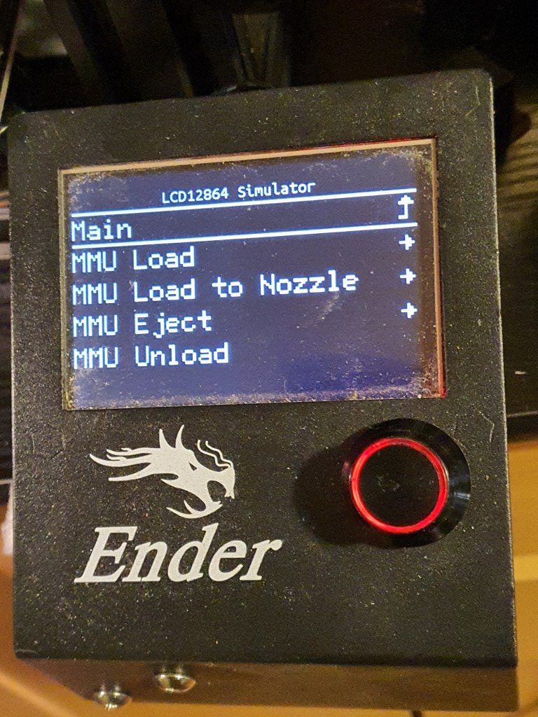
I discovered that the dual display I now use for the Ender3 will only work for Marlin LCD and no longer for TFT, since the serial TFT pins will be used to drive the MMU2S unit.  I exchanged the TFT/LCD unit with the original Ender3 LCD, I kept this in storage and tested it today with the Ender mini E3 V2.1 , it works very well!

The twotrees SKR Mini E3 V2.1 motherboard is really perfect for the combination with the MMU2S and the new  filament sensor in the new hotend/extruder. The firmware has been updated to include the MMU2S and the AUX’s serial that was previously used for the TFT screen is now in use by the MMU!  It all works!!!

Now the next thing was to get the new extruder, F.I.N.D.A. and the filament sensr to work properly.

That took some time and next on the agenda is the filament management.

I already decided to go with the original Prusa filament box with plates to hold the retracted filament for all 5 spools. The spools themselves will hang at the wall, behind the printer.  I don’t have space for standing spoolholders.  Underneath the spools the filament box with plates gets its place on the wall and from there the 5 PTFE tubes will run to the MMU!

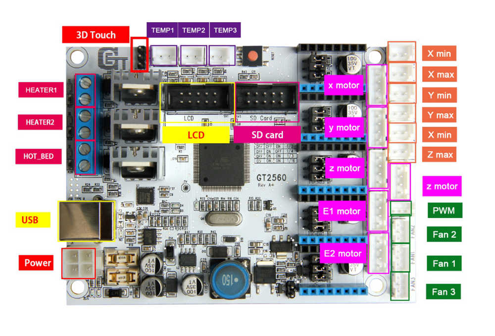
IndyMill CNC: GT2560 GRBL 5-axis controller

In my search for the best affordable CNC motherboard for my new to build Indymill CNC machine  I finally chose the GT2560 from Geeetech as best compromise.  At least for now, and maybe later I may change to an RRF3 board with a good remote CNC interface like the Mellow Fly-CDY-V2.

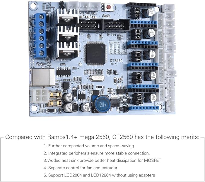
GT2560 3D Printer Controller Motherboard Mega 2560+Ultimaker Ramps 1.4 Geeetech Other Electrical Equipment & Supplies com Business & Industrial

The board has a budget price and utilizes an atmega chip with great performance.

The board does not come with the CNC GRBL firmware installed, you can get the required arduino library HERE for the Arduino Mega with the add-on RAMPS 1.6 board and HERE for the GT2560 integrated board!

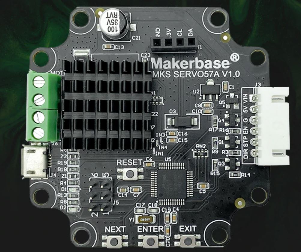
The nice thing about this board is that it can be flashed with the arduino IDE, and I like the board especially because I can plug in the NEMA23  closed loop stepper motor  cables directly in the driver connectors of the GT2560 board.  By doing so, I don’t need the lumpy seperate 6600 driver units and I never miss a step.  These closed loop drivers get attached to the rear of the Nema23 stepper motors and use the 24 Volts from the wiring to the GT2560 driver socket.  The max Amps is 4 Amps per unit and this is enough to have good CNC results.  I also added the tiny LCD’s into the closed loop units, this makes it possible to perform local management like the initially required one-time calibration of each stepper without the need for a PC. And= the display also shows the status of the stepper motor (errors, missed/corrected steps etc).

The required Gcode can easily be made with Esticam.  I first make my design in Openscad, export the design as .STL file in the highest resolution ($Fn at 128 or higher) and import the STL file in Esticam.    Then I use Esticam to send the Gcode via a USB cable in the GBRL format to the GT2560 board.  BUT- it is also possible to save the CNC file output from Esticam and put it on an SD card.  The LCD unit that is attached to the GT2560 accepts SD cards (formatted as FAT 32) so you can work independantly of a PC.

Or- you can connect your Mega2560 to a Raspberry PI and use the Raspberry PI as webinterface , to control your CNC machine via wifi from your PC or phone/tablet.

Please read on about how I use this setup for my IndyMill CNC machine!


IndyMill CNC machine

Since Corona was still around (May, 2021) , I had some time available to spend on other things than just work.

I already had an upgraded 3018 CNC-machine with a 0.5 kW spindle motor,

and a simple GRBL 3- axis board that works very well.  But- it would be nice to make a CNC machine that can really work with aluminium and possibly also with copper and brass.  I have already done some research in the past about what sort of CNC machine would be right for my goals. And the IndyMill CNC macine was already on my mind for over half a year.  So-last week I ordered the manual and the steel plates

for the build and ordered some other parts from Ali.  I also have quite a lot of parts on stock, from my 3d printer supplies.  The Nema23- motors and the extrusion, motherboard, drivers, power supply, switches and probes are already available.

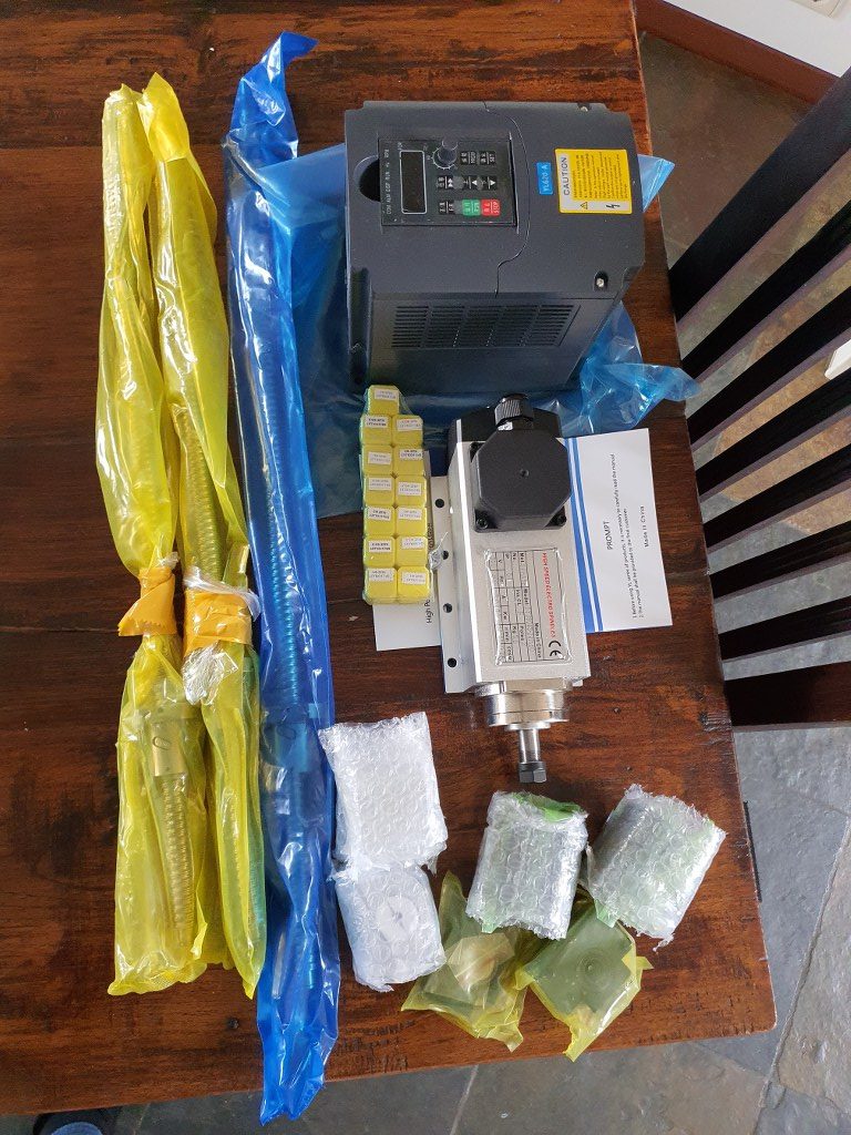
2021-5-09; First parts delivery for the Indymill: 3 ball bearing leadscrews with kit of end bearings and screw block holders, the frequency regulator 1 phase in, 3 phase out and the 1.5 KW 3 phase spindle of 3.6 kilograms

The required printed parts are being printed right now (early May-2021). I am printing all the upgraded STL’s, latest version as these are freely available  on Thingiverse (just search for IndyMill) .  And then you see the power of sharing: the design was already great, and with the upgrades it got even better.  The upgraded versions of the mounts for the linear bearings are really a lot sturdier than the original design and the new endstop holders are very handy to have.

I roughly calculated the costs for building this machine and it was a lot cheaper than buying a similar CNC machine of this size.  If you purchase wisely, the costs for all materials can be just under Euro 1000, if you follow the original BOM and including the 1.5 KW air-cooled spindle motor with regulator…

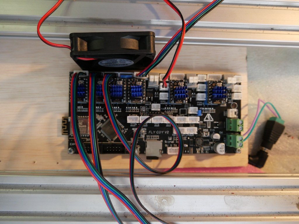
If you want to install another board than the standard Arduino UNO with the standard Arduino CNC shield,  this can set you back an additional amount of 120 to 500 Euro’s.  I use a FLY_CDY_V2 with Mellow’s original TMC2209 stepper drivers. DO NOT FORGET to set the switches on the underside of these steppers to ON if you want to use sensorless homing!

My add-ons  to the original build:

  1. Currently I use a 10 Amps detachable 24V PSU, will become a 30 Amps one.
  2. Sesorless homing with the use of a FLY-CDY-V2 motherboard and TMC2209 stepper drivers.  This works awesome but I moved on to add endstops and make a more stable and exchangeable setup.
  3. Original  mounts and usage of the ball bearing screw nut’s holder, and of the BK12 nd BF12 original bearing holders to keep the ball bearing screw from moving the wrong way.
  4. Altered Z axis setup with a better nut holder, and a better top bearing
  5. .
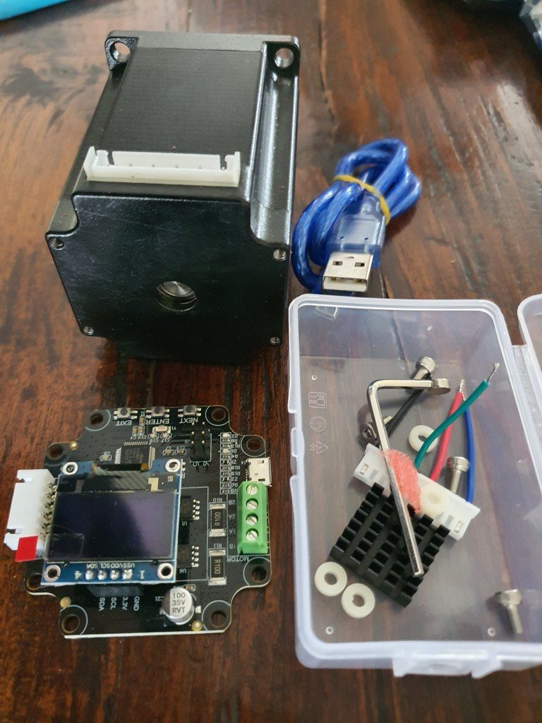
  6. Closed loop NEMA23 stepper motors drivers MKS Servo57A V1.0 will be fitted to the rear of the steppers, still to be mounted but will conflict with sensorless homing

    Nema 23 stepper with the Closed loop kit
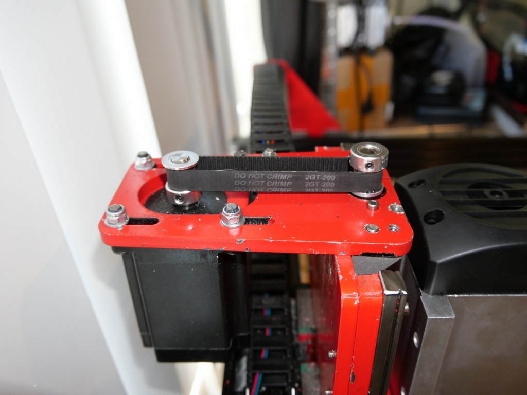
  7. 10 mm GT2 200mm belt between the Z motor and the Z-leadscrew with GT2 10mm wide 16-teethed wheels
  8. Add a ‘CNC pendant’ manual control device.
    • On the Duet support website a project is available to convert such a device to a serial interface, with a programmed Arduino (pro) mircro or -nano built-in the device:
  9. Solid connection plate between the rear side of the upper and lower linear rails of the X-axis. Still to come.
  10. Piezo-probes on all axes’s start- en end positions, instead I first setup the FLY CDY V2 reprap board with TMC2209 and sensorless homing, and later with mechanical endstops.
  11. Coolant mist installation and fluid gathering-, pump, reservoir et cetera is ordered. Stll to be installed, and the pumps were not supplying sufficient pressure for the flood mist, have to look for another solution.
  12. Independantly driven (and independantly finetuned homing) Y-motors to prevent any possible problems between left and right. This works flawless with the FLY_CDU_V2 reprap setup but it took me quite some hours of finetuning to work with the 3.5 kilogram heavy spindle motor…
  13. 2080 profiles all around (also front and rear) with 4 extra-wide corner brackets underneath.  I chose to implement this differently with 3 additional bottom connections and corner brackets, since I need the front of the frame to be low and give way to the spindle vacuum hose.

    Amd – the frame as it is ready, but with the spindle holder of the 500 Watt motor. I will not use this motor after all for this build–
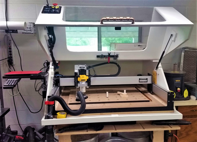
  14. Smart enclosure with Scheppach vacuum cleaner connection like this example from https://www.shophacks.com/cncenclosure.html#/  THIS IS REALLY NEEDED! Advantages of using an enclosure for your CNC router - SHOP HACKS

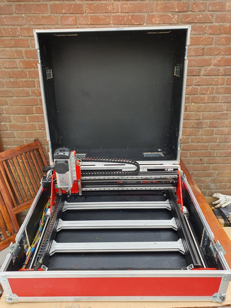
    My solution for an enclosure ia a 84x78x45 cm flightcase
  15. Protecting guards for all leadscrews and linear rails (ordered in China)
  16. Later if possible: Wheels on the rear or on 1 side and a handle on the front (or other side) to stow and store the machine easier
  17. Easily detachable control unit(s) with solid connectors

I started with a FLY_CDY-V2 reprap board to experiment with reprap CNC and the webinterface that has been developed for this setup.

This is achieved with  smart dual homing of the dual Y axes, and gives me a lot more control on the machine. It is also already possible to just send GRBL-based Gcode to the USB port of the machine and use the reprap FLY board simply as gcode-interpreter to steer the machine.  But for now I use the webinterface to upload and run any gcode.nc CNC file, which works perfect!

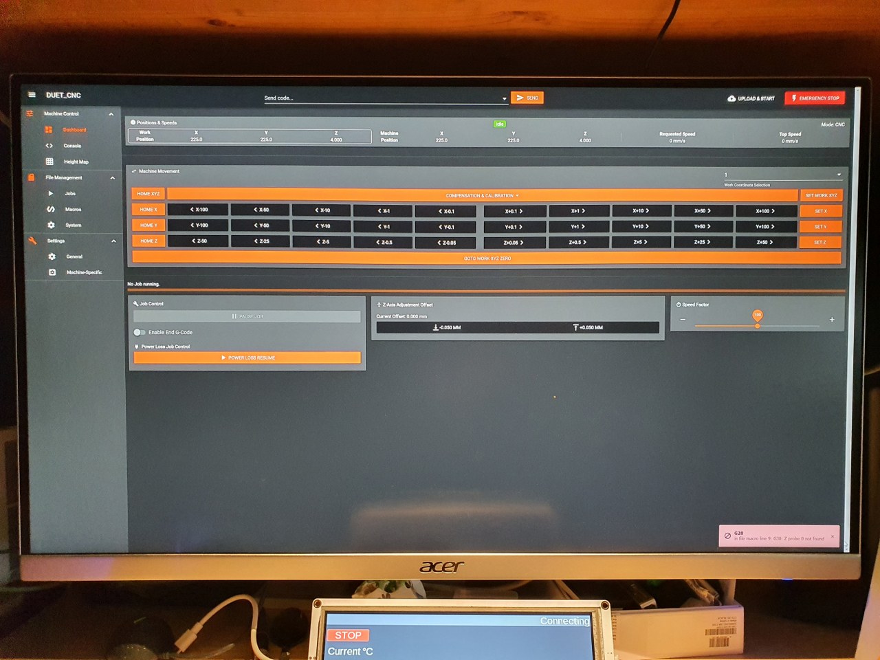
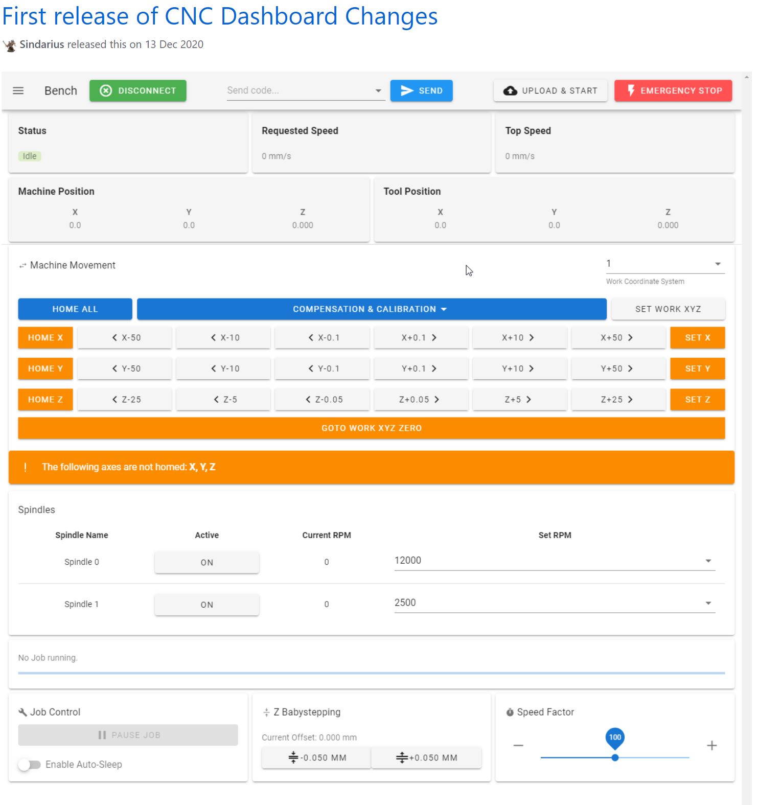
Picture of the CNC-adapted and already available webinterface for reprap, especially tailored for CNC (by Sindarius, work ongoing):

Pictures are already published about this build!

Penta extruder on A30M

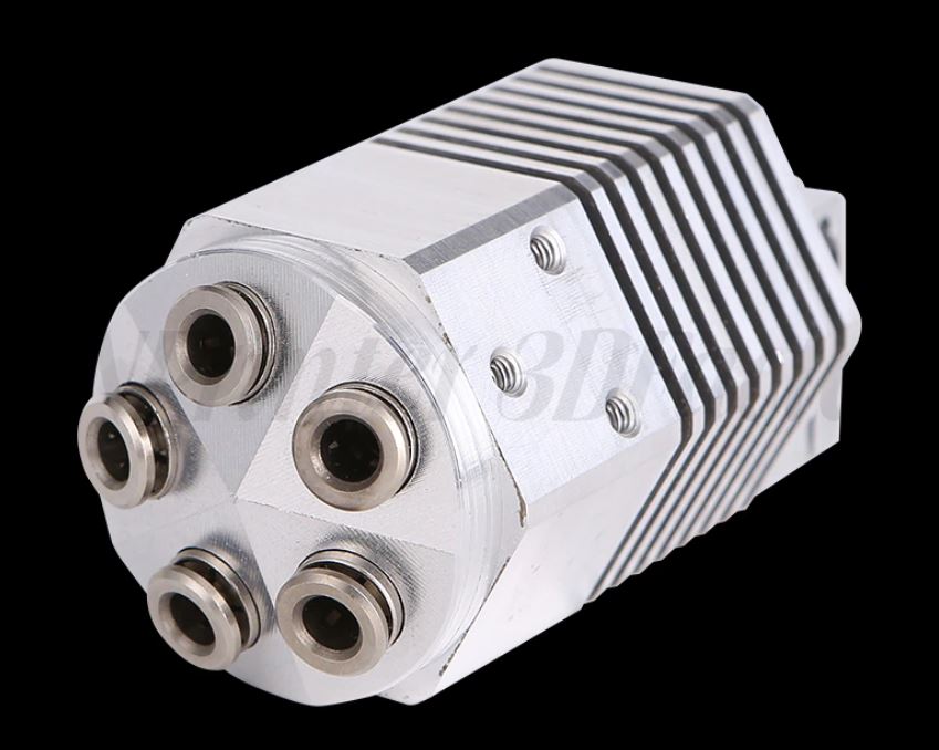
Today I received my 5-in, 1-out hotend, non-mixing  air cooled with 1 nozzle and 1 heater//temp sensor.

I will install it on my A30M with the Duet2wifi board+extension board (5-fold with plug-in drivers). The A30M already has independant Z-stepper motors.

The Duet2wifi has 5 stepper ports, and the expansion board also has 5 stepper ports.  X,Y,2xZ, 5 Extruders is a total of 9 so this will indeed fit!

I will make new wiring for the 5 extruder steppers on top of the A30M frame with 5 bowden tubes to the hotend.  Since the hotend is non-mixing, this will be a  simple task to get into config.g.  For the slicer- it will also be easy. Just add the extruders to a total of 5 pieces. Add the correct filaments/temps/ no offset so set offset X and Y to 0..  The work will primarily be in  the tool changing files for T0-T5 where retraction- and extruding  settings will be needed.

For the hotend, I have a new setup available that allows me to quickly change the nozzle.

This will make it possible to use this setup for all kind of applications.

Mellow FLY-CDY-V2 motherboard

recently (3-2021) I have been setting up my new 3d printerboard from Mellow, an STM32 board that is named FLY CDY V2. It is (almost) fully compatible with Duet2Wifi and also uses its wifi-based 3d printer management system DWC.

The config file I made for this setup is HERE

The FLY_CDY_V2 board comes completely empty so I added the firmware.bin in the /sys directory, after I had an empty SD card filled with the clean reprap directories and -files.

Next to the firmware.bin. also a board.txt is required to be available in /sys with some settings, with the following content:

//Config for fly-CDY
board = fly_cdyv2
led.neopixelPin = D.15;
//wifi pins
8266wifi.espDataReadyPin = E.10;
8266wifi.TfrReadyPin = E.12;
8266wifi.espResetPin = E.11;
8266wifi.serialRxTxPins = { D.9, D.8 };
heat.tempSensePins = { B.1 , A.3 , C.4 , D.14}; be aware that D.14 is not a temp pin but a heat pin, is this wrong??
stepper.numSmartDrivers = 6;
serial.aux.rxTxPins = {A.10, A.9};

This board.txt is already OK for 2209 drivers and for the use of the neopixels output.

In the pdf that is provided by Mellow on the Github page for the reprap STM32 boards, section FLY-CDYV2, everything is explained as to get wifi up and running,  configure config.g et cetera.  

In my config.g everything needed to work properly is already done, as is with my board.txt.

I made the config for a.o. a  Cartesian printer with single X,Y,Z steppers and a triple hotend with 3 extruders, 1 heater and 3 nozzles.
Included is: Neopixels, BLTouch, 3 filament sensors on the X,Y- and Zmax inputs, active fans for hotend tool on fan1 and object on fan0
If so desired, sensorless homing is possible with the correct driver boards. In this version, 3 optical endstops have been used on inputs xmin, ymin and zmin.
Retraction is set OFF in this firmware by default, but may be swiched ON to make the triple hotend drip less (2 mm retract and -0.5 extrude without Z-hop), do experiment with these settings!
Please be aware that some pin names for the FLYCDYV2 board differ from the Duet’s naming convention like “bed” versus “bed-heater” et cetera.
Plus, some typical Duet2wifi extensions are NOT available like the GPIO bus.
The FLYCDYV2 has some interesting standard extra’s though, like the BLTouch connector with power, driver pins and Z probe pins, the Neopixel connector AND the 6 driver slots and 3 extruder heaters/sensors/fans!
It is quite simple to change this setup to a dual Z axis with independant Z-motors and either single extruder or a dual setup, single or dual nozzle, mixing or non-mixing.
Please see my complete ready-to-go config directory setups for this board HERE to get you  started! 

Also: Check my CNC Indymill running with the FLY-CDY-V2

Please donate $1 to my paypal account if you use (parts of) my developed materials so I can continue to share nice stuff for you to download


Magnetic dual parking extruders reprap I3 Bear with Duet2wifi and sensorless homing

My most recent and probably last build from scratch is the dual carriage I3-based printer as shown in the below picture, in the building phase.  This printer can be used either for 2 colors or for printing with soluble support PVA filament.

I decided to use sensorless homing for this build due to problems when using endstop switches.  When using endstops, problems may come up because f.i.  homing to the left means that the left tool will be parked against the endstop, should you use endstops.  Same on the right hand side when the right hand tool is parked.  I encountered difficulties that the driven sensor carriage in the middle can then get into an unknown state (or position) when both tools (carriages) are in the parked position.

If you home one of both Tools with sensorless homing, the status of the sensor carriage is always automatically known.  So, since the XY position of the center (sensor) carriage is known you can always do a Z-homing at any given X-Y position and you can also do G32 and G29 without the need to carry T0 or T1 along.  And- you can easlily reset an unknown status of the sensor carriage by homing it, either left or right.

Get my build plans and Configuration files for Duet2wifi HERE

The box at the left rear is for the Duet2wifi board.  The 24V fan-regulated power supply is already positioned at the rear,  right side.

The main challenge with this build was to get the settings perfect for the dual tools.

It took me 2 months before I got it to work perftectly for both PLA and/or Petg.

As with my previous dual color dual nozzle builds, the basics is very simple. Just define 2 tools with 2 heaters, 2 temp sensors, 2 fans et cetera.

I already envisioned the approch with the slicer(s): All offsets are done ONLY in firmware, NOT in the slicer! As far as the slicer(s) is/are concerned, the nozzles of Tool0 and 1 are at the same (X0/Y0) offset.

For the Duet, the only addition in the slicer is an M0 command as stop command for the printer.  Define 2 nozzles of 1.75mm without any offset and you’re done in the slicer.

Then, you will need to set everything in your config.g at the tool section like XYZ offset and so on.

I decided to get T0 as reference, and set everything to 0 there. X=0, Y=0 and Z=0.  Then, measure the differences at T1 versus T0 with calipers to start with and inport these values in the T1 toolsection in config.g.

Start a testprint and measure what to amend, take little steps and the metrics are done!

But- the hard part is- as I experienced- to get good prints without blobs and unexpected stringing, both incoming as outgoing (into and out of the printed object(s).  Drying the filament also helps a lot!

In the end, I just took the same approach as with the tool settings: As little as possible retraction settings in the slicer and all except the basic print retractions are now in the configuration files that are called upon Tool changes tpre.g,  tfree.g and tpost.g (for T0 and T1).

This means that you can play with retracting and extruding of filament length and speed directly at, during and after Tool changes.  And- in my experience it is all affected by the type of filament you use and the temperature you are at with the hotend. Also, the fact whether you use a lower temperature during waiting has great impact.

In my experience, you should finetune the config settings for the mentioned settings per object and per type of filament.

Therefore, I decided to used this printer for only 1 goal and make the settings perfect to accomplish this goal.  Right now, I have optimized this printer to print 1) PLA from 123print in the Netherlands, of a specific type and 2) PVA from the same supplier.  This gives me the possibility to print complex objects with soluble supports and it works extremely well at doing this!

PM: I also added LED lights on top of the printer as an integrated feature.  This makes use of a heater pin as GPIO (with a M42  P [pin] S[value intensity]) command), like the solenoids that I use to catch the carriages T0 and T1. To come from the 3.3V and max 1mA from the GPIO pin to the required 24Volts, I used small mosfet boards.  All programming is done in the Duet’s config and macro files, view the below example of my stop.g file which is called from the slicer’s stop setting: M0.

; stop.g
; called when M0 (Stop) is run (e.g. when a print from SD card is cancelled)
; Also called by slicer end gcode by M0
;
M400 ; Finish move queue
M117 Cool down ; Update the LCD screen with “Cool down”
M83 ; Extruder relative mode
G1 E-2 ; Retract filament 2mm for both extruders !!
M106 S255 ; Fan at 100 to cool nozzle and bed
M104 S0 T0 ; Extruder T0 heater off
M104 S0 T1 ; Extruder T1 heater off
M140 S0 ; Bed heater off
G28 X ; Home X
M220 S100 ; Set speed factor back to 100% in case it was changed
M221 S100 ; Set extrusion factor back to 100% in case it was changed
M42 P4 S0 ; Magnet T0 off
M42 P5 S0 ; Magnet T1 off
M104 S41 T0 ; set extruder T0 to cool down
M104 S41 T1 ; set extruder T1 to cool down
;M568 R41:41 S41:41 ; set standby and active temperatures for tools 0 and 1 (or single M568 T0 R41 S41)
M116 ; wait for Tools actions as specified in above M568 instructions
G90 ; Absolute positioning
G1 Y200 ; to get objects removed easier, move bed forward
M106 P0 S0 ; Fan L object T0 off
M106 P2 S0 ; Fan R object T1 off
G28 X ; Home X
M84 ; Steppers off
M98 P/sys/ledflash.g; Perform execution of ledflash.g in specified directory
M42 P6 S0.008 ; Led light setting almost OFF
M117 Jantec=done! ; Update the LCD screen with “Jantec=done!”

G1 X5 Y5 ; Move to corner
M140 S{print_bed_temperature} ; Set bed temp
T1 ; Select extruder 1 (or 0 depending on how your printer is set up)
M104 S{print_temperature} ; Set extruder temp
M116; Wait for temperatures


Please donate $1 to my paypal account if you use (parts of) my developed materials so I can continue to share nice stuff for you to download


Our 3d printers, managed by OCTOPI and Duet Web Controller

Above: Our Dual Bear I3 dual color 3d printer with independant carriages, this one does not run octopi and is remotely managed by Duet Web Control (DWC).

Above: The Voron 2.4, dimensions 300x300x220 mm

Prusa Bear I3plus with mods like dual Z axis control. This printer runs Duet and  DWC.


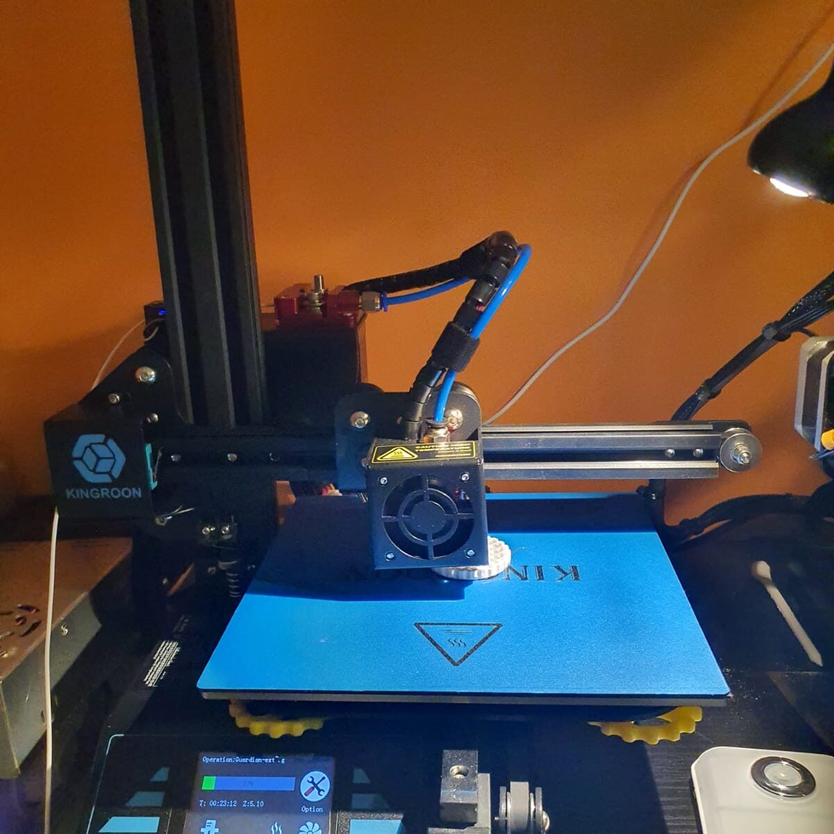
Kingroon Kp3S heavily modded with new firmware and tool fan. This printer runs with Octopi for remote management.


Twotrees Sapphire PRO with new firmware, also with octopi.


Voron 2.4 for Nylon and ABS printing, with external exhaust and 300+ degC printhead, bed up to 150 degC.  Also runs octopi.


Prusa i3 mini original, the production monster for PETG. Also on octopi.


And the Twotrees Sapphire pro, our perfect printer for fast production, also on octopi.


And the multicolour completely rebuilt Geeetech A30M dual head printer with a new Duet2Wifi motherboard, dual Chimera heatblock and direct drive extruders.  This one runs Duet with DWC instead of Octopi.


Our 3d printers, managed by OCTOPI OR Duet’s web-based app

Above: Our Dual Bear I3 dual color 3d printer with independant carriages, remotely managed by DUET’s webinterface

The Octopi solution works with a Raspberry PI, and on it the Octopi firmware.  The device you set up on your wifi and you connect it to your 3d printer’s USB. Then you have a web interface on the Raspberry’s IP address that allows you to manage all the things about your connected printer.  All the settings like temperature, mesh, and basically anything else you can manage through a local LCD.  And- you can upload your jobs to the raspberry and start/manage and adjust temperature and such.  What I really like is that you can connect a raspberry camera and follow your jobs.

The Duet I find in use and possibilities more pleasant. because in addition to everything that the octopi can, you can also modify the system files online.  And printer updates can do, directly in the firmware.  Moreover, you do not need a separate box because the Duet2wifi already has everything on board.

The disadvantage is that you can’t attach a camera to the Duet. There is a possibility em an IP camera to integrate into the DWC, Duet’s web based remote app.  And such a wifi IP camera is easy to make yourself with a cheap esp unit.


Above: The Voron 2.4, dimensions 300x300x220 mm

Prusa Bear I3plus with mods dual Z axis control


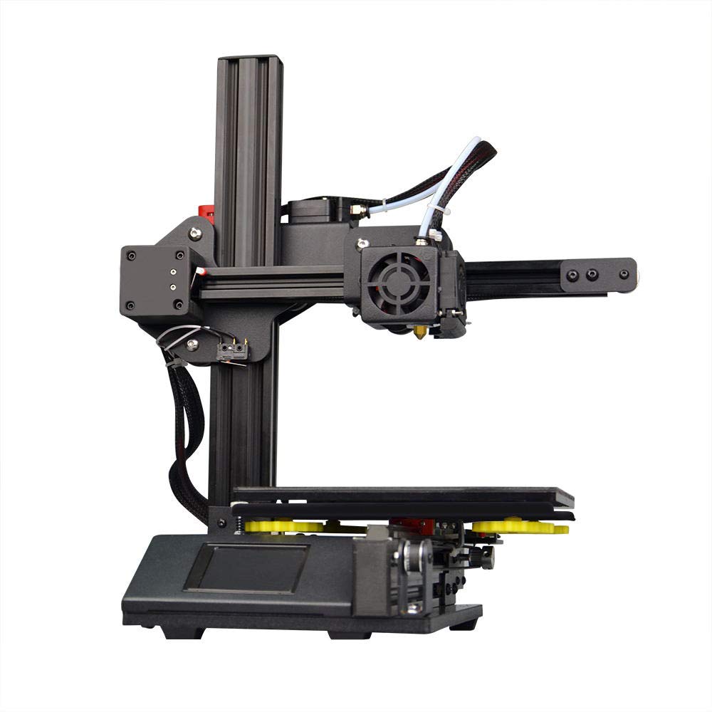
Kingroon Kp3S heavily modded with new firmware and tool fan


Twotrees Sapphire PRO with new firmware


Voron 2.4 for Nylon and ABS printing, with external exhaust and 300+ degC printhead, bed up to 150 degC


Prusa i3 mini original, the production monster for PETG


And the Twotrees Sapphire pro, our perfect printer for fast production


And the multicolour completely rebuilt Geeetech A30M dual head printer with a new Duet2Wifi motherboard, dual Chimera heatblock and direct drive extruders


VORON 2.4 20″x20″x20″ and DUET2WIFI

Get the documentation, specs, config.g, macros and build docs

LEES IN HET NEDERLANDS

After my succesfull buildproject of a Voron 2.4 3d printer in the fall of 2020, I still wanted a really big 3d printer with a print surface of over 20x20x20 inch.

My Voron 300x300x300mm build plate size

Imagine to have a print of more than double the size compared to the below picture!

During the build and at using the Voron 2.4 printer, I found the documentation on the hardware build really excellent.  But, the electronics part was scattered around several places, and although the Klipper implementation is very good I have experienced that the combination of 2 SKR 1.4 turbo motherboards with an Octopi controller does not provide enough operational stability to me. And- I feel the need to control more settings than I can do with the Klipper solution.  I think I probably am just more into the Duet and the reprap solution than the Klipper one, due to previous positive Duet – and MKS reprap experiences.

In a couple of previous builds I used a Duet2wifi, and I also experienced the add-ons for Duet2 like driver boards, PT100 boards and more hardware that is also very well implemented in the new RRF3+ firmware.

Duet wifi board , used for my dual head setup I3bear-based with sensorless homing

Reasons enough for me to choose the Duet2 and the 5-ports expansion board , or possibly an additional Duex board for my new to build Voron 2.4 ‘big 3d printer’.

At this page, I will share my progess on this build.

I have all required hardware laying around and since I already built a Voron 2.4, I will first focus on the electronics.  For the hardware, I still need the plexiglass sides, top and front doors.  I  do have all extrusion, bed, bed heater 230V, linear rails, all printed parts and so on, neatly stored at home.

So, I am setting up the electronics to know beforehand that everything works well.  I don’t want to start building the hardware and find out afterwards that my Duet2wifi will not do the job I want it to do.

Yesterday (October 4th,2020) I put the electronics and config.g together. I used:

  • Duet2wifi board with 24V PSU and 4.3 inch TFT/LCD
  • 5-port expansion board with 4 plug-in 2209 drivers V3.0
  • Z-switch mechanical
  • X-and Y end switches (hall-effect)
  • Hotend 24V with NTC connected including tool’s fan (I am missing the PT100’s interface board, have ordered one but I did this before so should be no problemo)
  • Hotbed simulated with another hotend including NTC
  • Stepper motors connected to X(0),Y(1) and 1 x  stepper on the expansion board Z(5) (Driver5)

The Duet2wifi board is a Chinese MKS clone with electronics version 1.02 which works fine.  The expansion board is also a Chinese one, but this is a bare-bone  implementation of the 5-ports driver add-on board that comes without drivers.  the nice thing about this add-on board is that drivers can be plugged in directly.

The Duet2 came with firmware 2.1 installed.  To get to FFR3.1, you must first install 3.0 and after this, you can move to 3.1…  be aware!

After updating the paneldue and the Duet2wifi board, I activated the wifi and put the ssid and PW in. (This procedure goes via USB between PC and Duet, using a terminal emulator like YAT)  This is a bit tiresome but given the security you get from it, I feel it is OK.

The settings that are needed to get the Chinese expension board to work are not too difficult.  Add the Z-drives, and change some other settings. On top of this page, you can download the latest doc with all info I have, and a direct download to the adapted config and macros is available in the documentation.

The rest of the build including photos will be here later!

Update 3-2021: I recently built 2 other 3d printers using Duet2wifi boards: a cartesian I3 with independent extruders and a Delta 2GS.  Not much time to work on the big Voron.  I also just rebuilt my Geetech A30M  (330x330x400mm build size) from the smartto board to Duet2wifi, Check ik out on this site!

I will probably not build the big Voron 3d printer after all,  and if I don’t, I will rebuild my existing Voron 2.4 300×300 from Klipper, octopi and 2x SKR1.4 to Duet2wifi+Duex.  That will be interesting and achievable.

UPDATE 12-2023:  I finally built me  a large Voron2.4 l!

Since I am currently running 10 different 3d printers, my space is getting cramped in the house. I don’t want to expand into another room.  One should be enough. Having more printers gives me the best possible fit of a specific  filament type per printer.

The Voron is due to its perfect prints with ABS really only used for/with ABS or nylon.

The I3Bear dual carriage works best with dual PLA or PLA&PVA.

The Prusa mini works perfect with PETG

The I3Bear solo goes perfect with PETG or PLA.

The A30M & its mixing extruder goes perfect with PLA and/or PETG

And so on….

3d applications – self-folding materials

3D printing became a hot item around 2016,  and quite a few 3d printing machines have been sold over the years.  But, at some point it seems that the use for products from these machines has faded away.

Due to the availability of 3D printers and the fact that these printers are getting better and are producing prints with better quality as they evolve over time, more applications have been developed.

In this article I will sum up a couple of these new areas in which 3D printing became a driver for new developments, which are sometimes just scratching the surface of possible future developments.

  1. Dental products.  For over 40 years , dentists are using Services from laboratories to produce Ceramic protheses for teeth.  The base for this is a mould, taken from the patient.  I recall that this was indeed not a very pleasant process for the patient.  This process was time consuming and it required also some adjusting and fine-tuning at delivering the protheses at the right place.   Currently all dentists are either producing the protheses themselves or use online deliveries that are mostly available with a production- and delivery time of less than 4 hours.  the process starts with a 3d-scan from the patient’s mouth, compared with (if available) older pictures and/or X-rays.  All is fed into a normal PC, and the software makes the 3d print data.  After that, printing the protheses is quite simple with the new ceramic printable filaments. Placing the protheses with UV-herdening glue means that someday we will be able to do this at home. Although the prepping of the place to put the protheses will still be done by a dentist, I presume.
  2. Technical parts.  For many tehnological industries the availability of 3D printers has made it possible to have faster development processes of new parts and applications,  You can think of modeling new tools,  household objects, cars and -parts, and so on.  Since new materials can be printed like aluminium, copper, gold, silver and carbon much is possible. After the developments has produced a complete product, mass-production can start and for this, the 3D design files can be handed over to make the work easy.nn In this way both time and money is saved.
  3. Art.  Maybe not the most obvious development yet, but lately I ran into some artists whom actually used 3D printing in most expressive ways, as art may do.  If you check the internet for this, some interstingexamples can be found.
  4. Medical developments.  Since 2017, a new development achieved the ability for 3D printed parts to shrink and expand, based on the printed structure.  Read this article about self-folding materials
  5. Fun printing. Many hobbyists are printing 3D objects just for fun.  To add-on applications to their 3D printer, build new ones or print household applications.


Kingroon KP3

This is my spare machine, wrapped in – to use when any other machine should have an unsolvable problem (at least- short term).  This 1st version Kingroon KP3 mini always works flawlessly on PLA and PETG. I did add some after market stuff like better cooling, new firmware et cetera.  If I use this machine, I always manage it remotely with an Octopi on RPI.

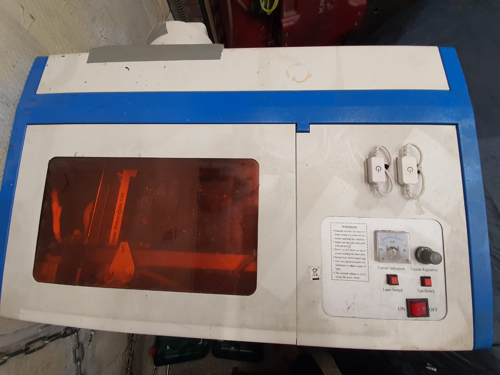
K40 lasercutter

My Chinese lasercutter which I bought back in 2014 has been upgraded over the years.  As many others do, I got the cooling system for the laser tube inside the casing, added some LED lights inside and also added an air pump for the laser head.

All in all the machine works fine now but the relatively small working area remains the bottleneck for using this machine for real interesting projects.

Mid-2020 I used the laser cutter for a couple of projects where I needed series of cut acrylic.  The machine handled this flawlessly, but I did put it outside to prevent any smoke from entering our home.

I do have some ideas about upgrading the machine with a larger workspace and put the electronics and water cooling system in a seperate housing.  No materials are needed for this, except 3 linear rails and some aluminium profiles.  But- (status May-2021)  I will start this project only if there is some work to be done with the machine since it is already working fine as it is, although the workspace is limited.

I use Inkscape (freeware) for making designs in SVG and import these .SVG files in K40whisperer (also freeware) which then  can send the required Gcode to the K40 lasercutter. This all works very well and fast, you don’t need a fast computer for this.  I use a 10 year old dedicated HP laptop for this.

In future use I want to make this lasercutter use the same board as I am using with my big LED laser cutter, so I can use GRBL on both.

As you probably know, a K40 or any other CO2 lasercutter can cut a specific kind of materials while a common LED lasercutter can cut other kind of materials better, due to the used kind of light on both which differ in wavelenghts.

The CO2 cutter can cut acrylic easily and the LED laser cutter can’t.

The LED cutter requires some sort of substance in the to be cut material to work properly.

Be aware that the security goggles you need also are specific for either macine.

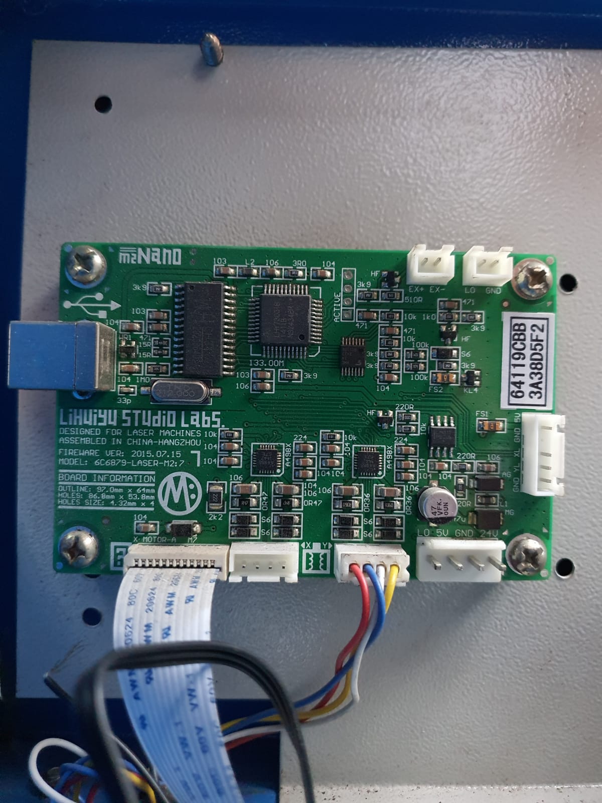
The original driver board of the K40 CO2 lasercutter

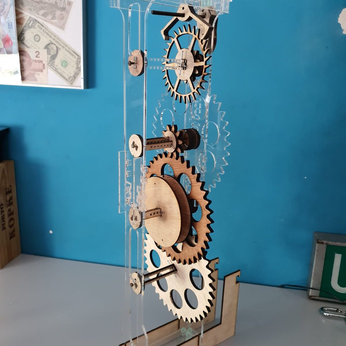
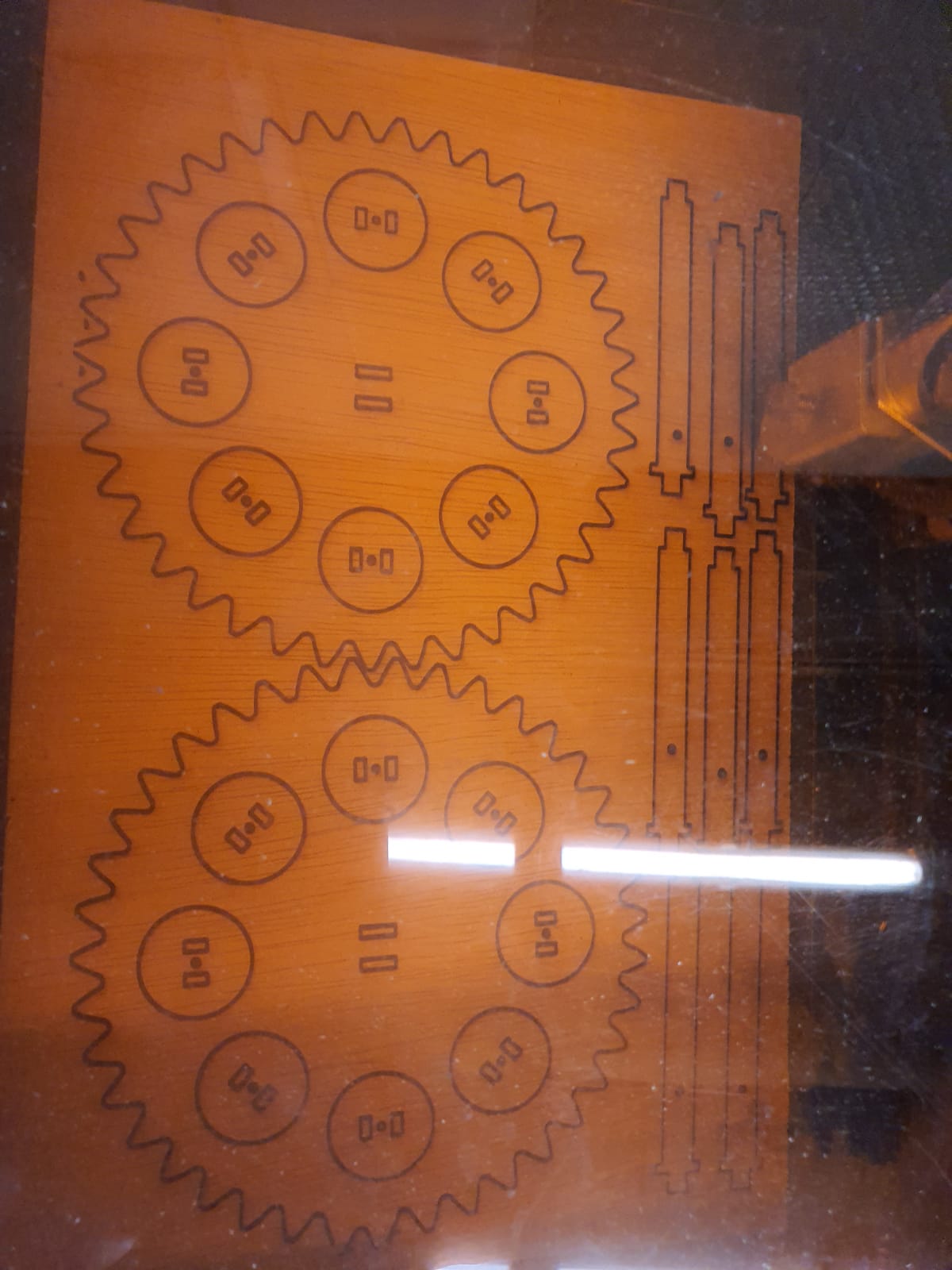
First cut on a piece of tripledeck 4mm multiplex for my clock pieces

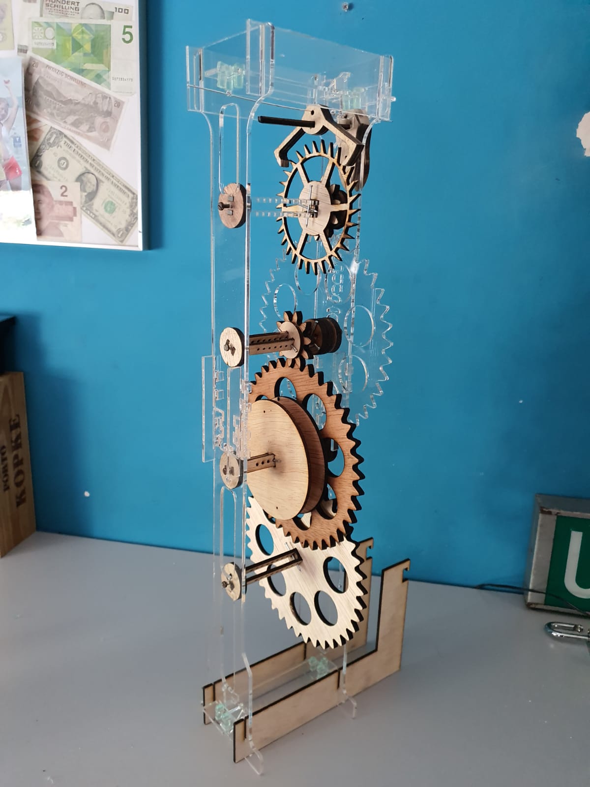
The clock’s interior and stand pieces, wood and acrylic. Both cut on the K40

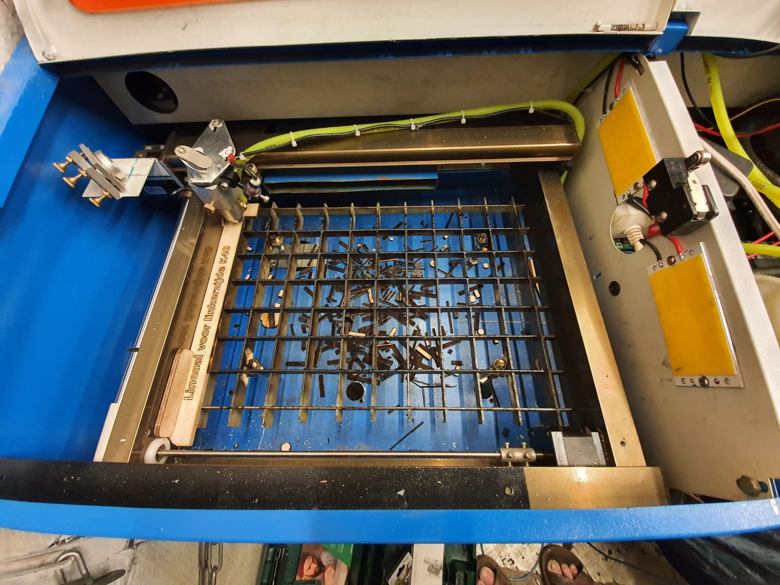
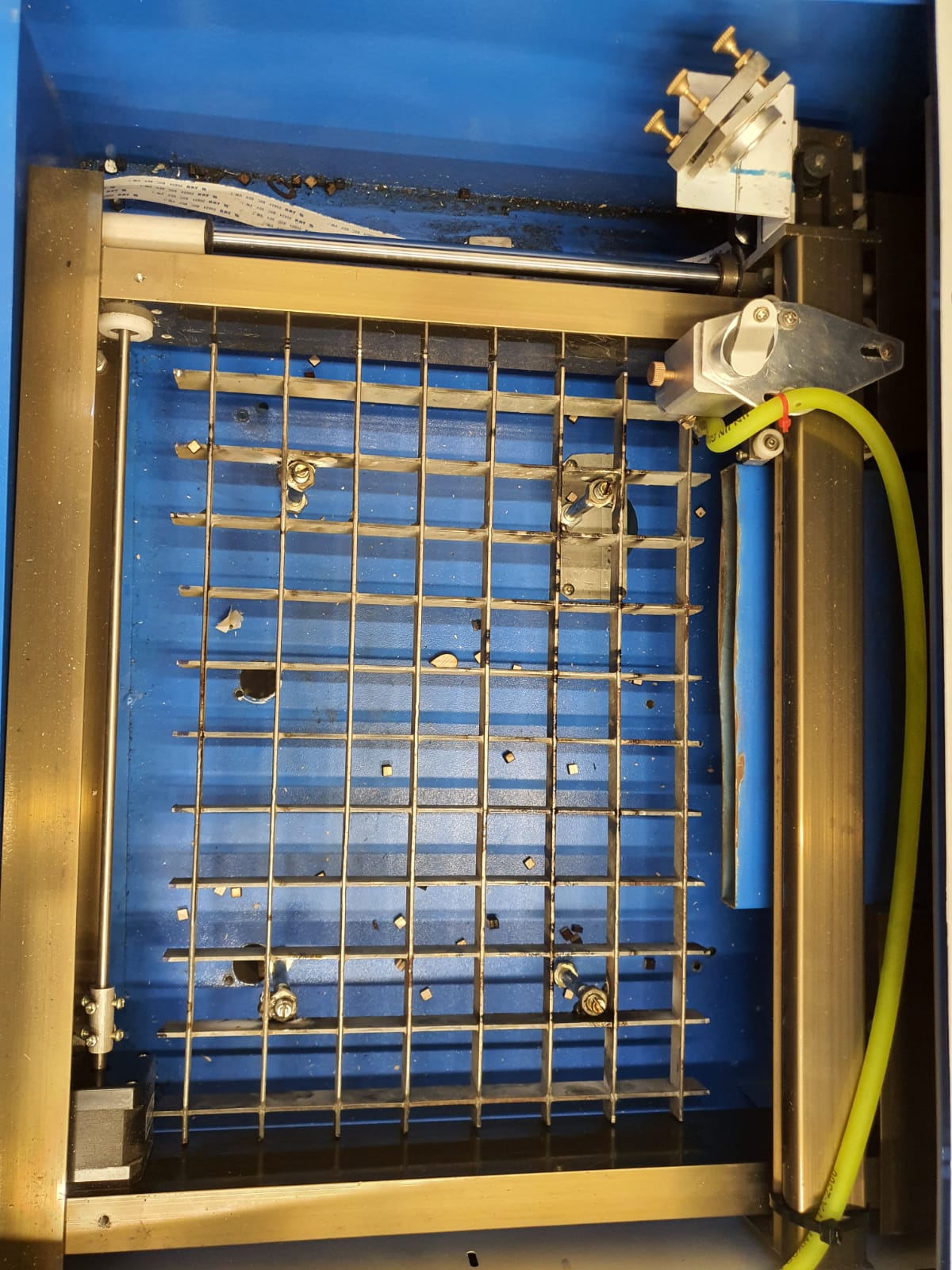
The inside of the K40’s work space with the debree on the bottom. The air hose is green silicon. Also added an emergency cutoff switch for the laser tube. open the hood and the power stops.

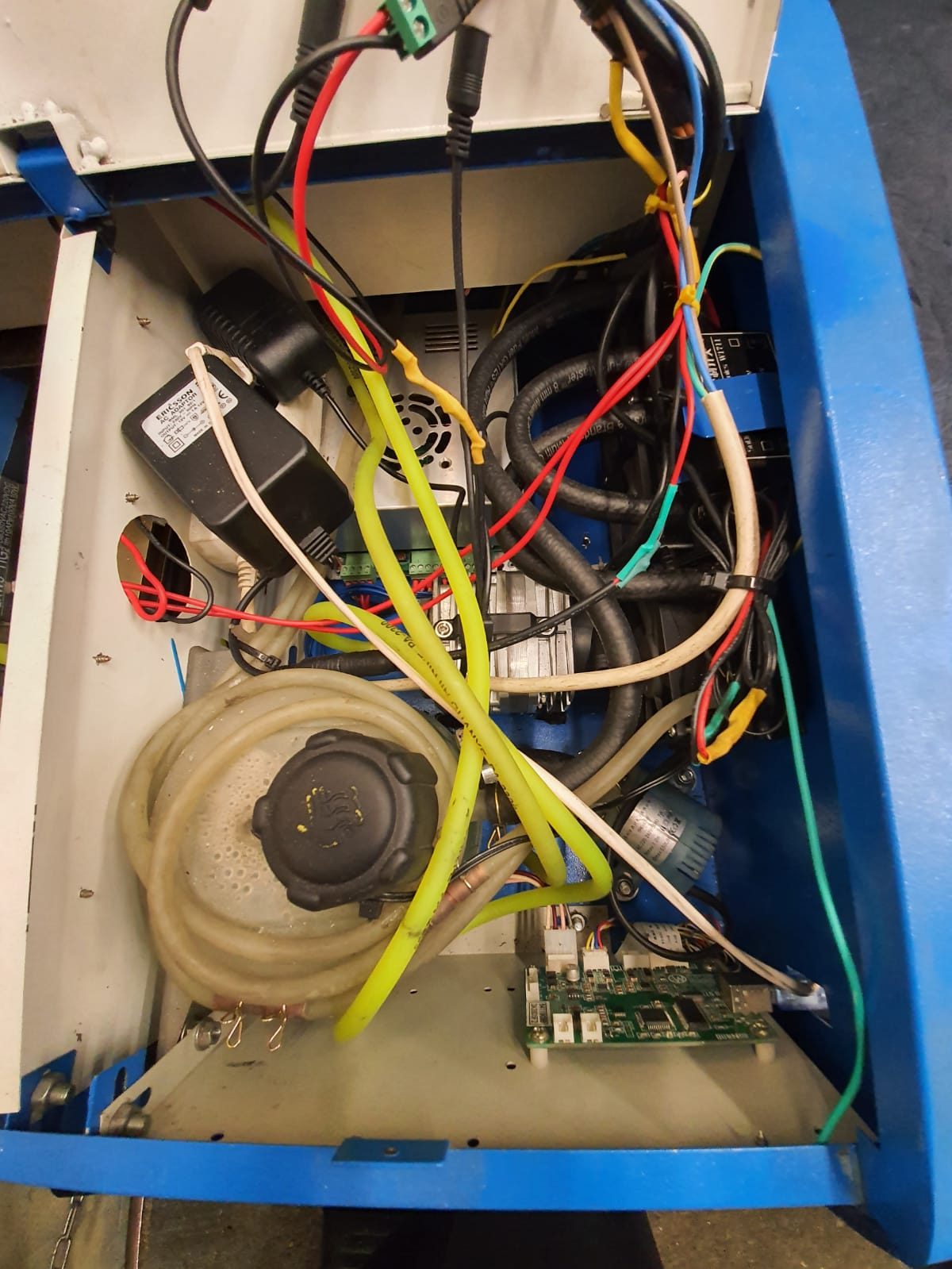
The electronics and water cooling on the Right hand side of the K40’s housing. The air cooled radiators are just out of sight to the most right hand side of the housing, 3 pieces of 40x40mm

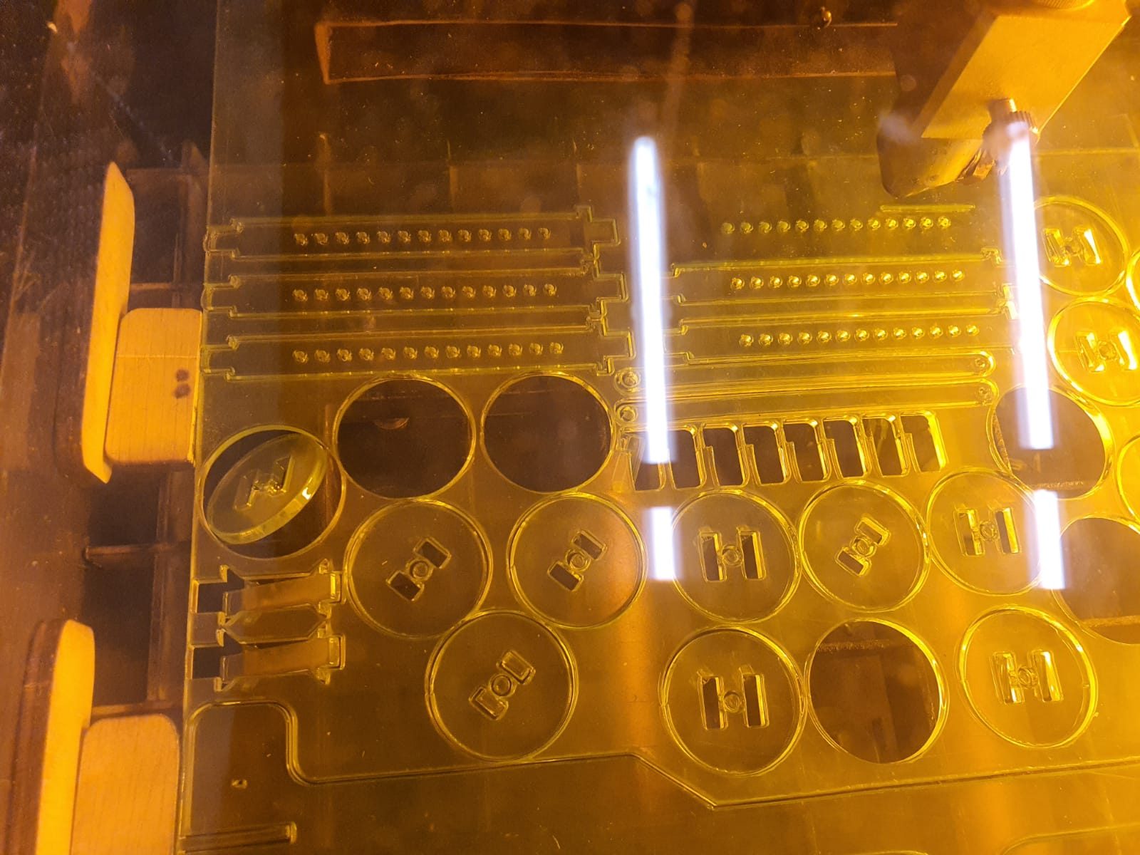
The acrylic cut for the clock, done in 1 time. This is 3 mm thick.

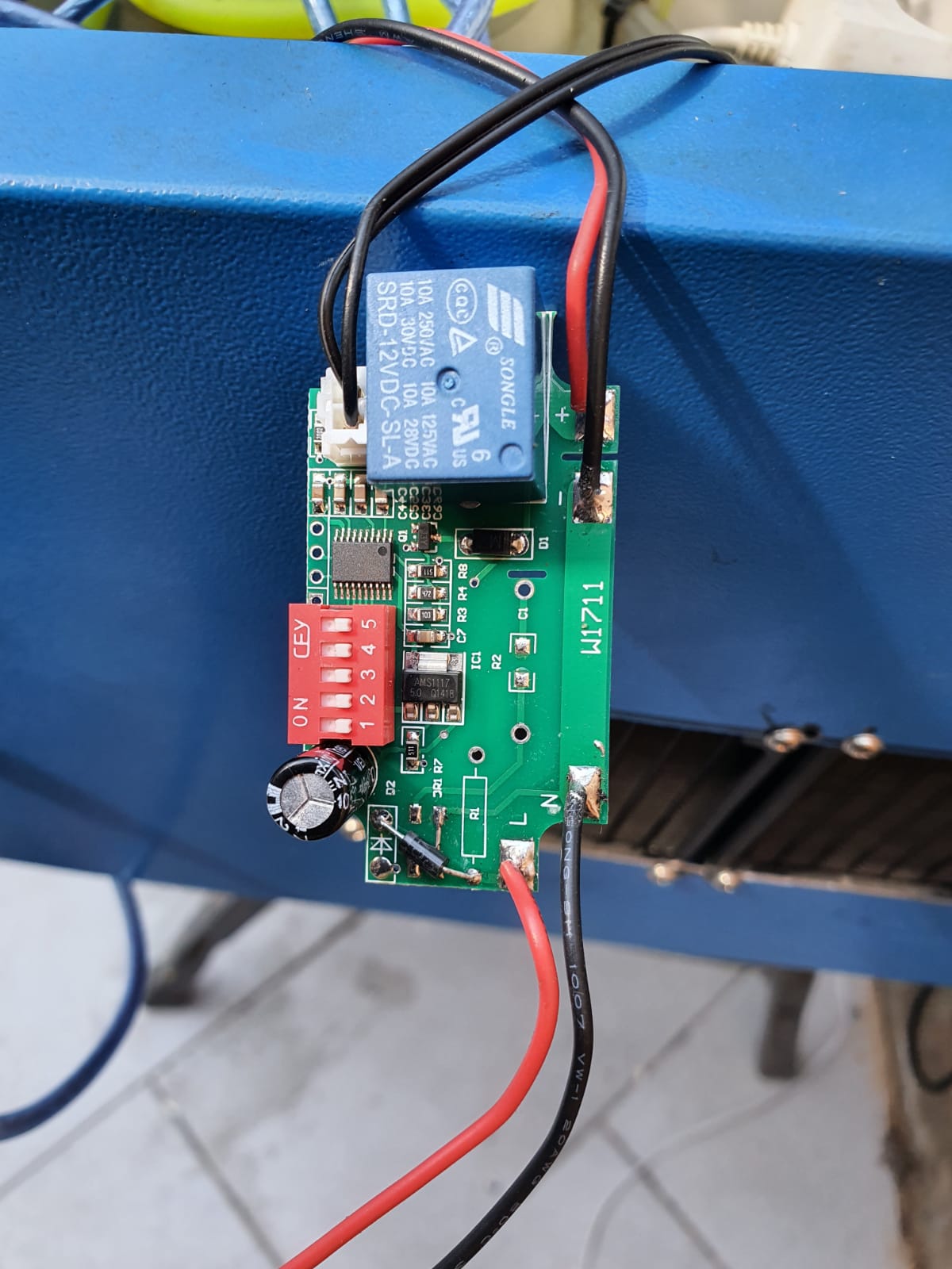
The thermostatic control of the coolant pump, taken out of its case to set the working temperatures

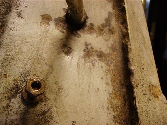
My solution for the cutting bed was to use an old footboard maze and I welded 4 nuts in it with long bolts that act as feet. This makes it possible to adjust the height 1x for optimum focussing the laser in the center of the to be cut material.

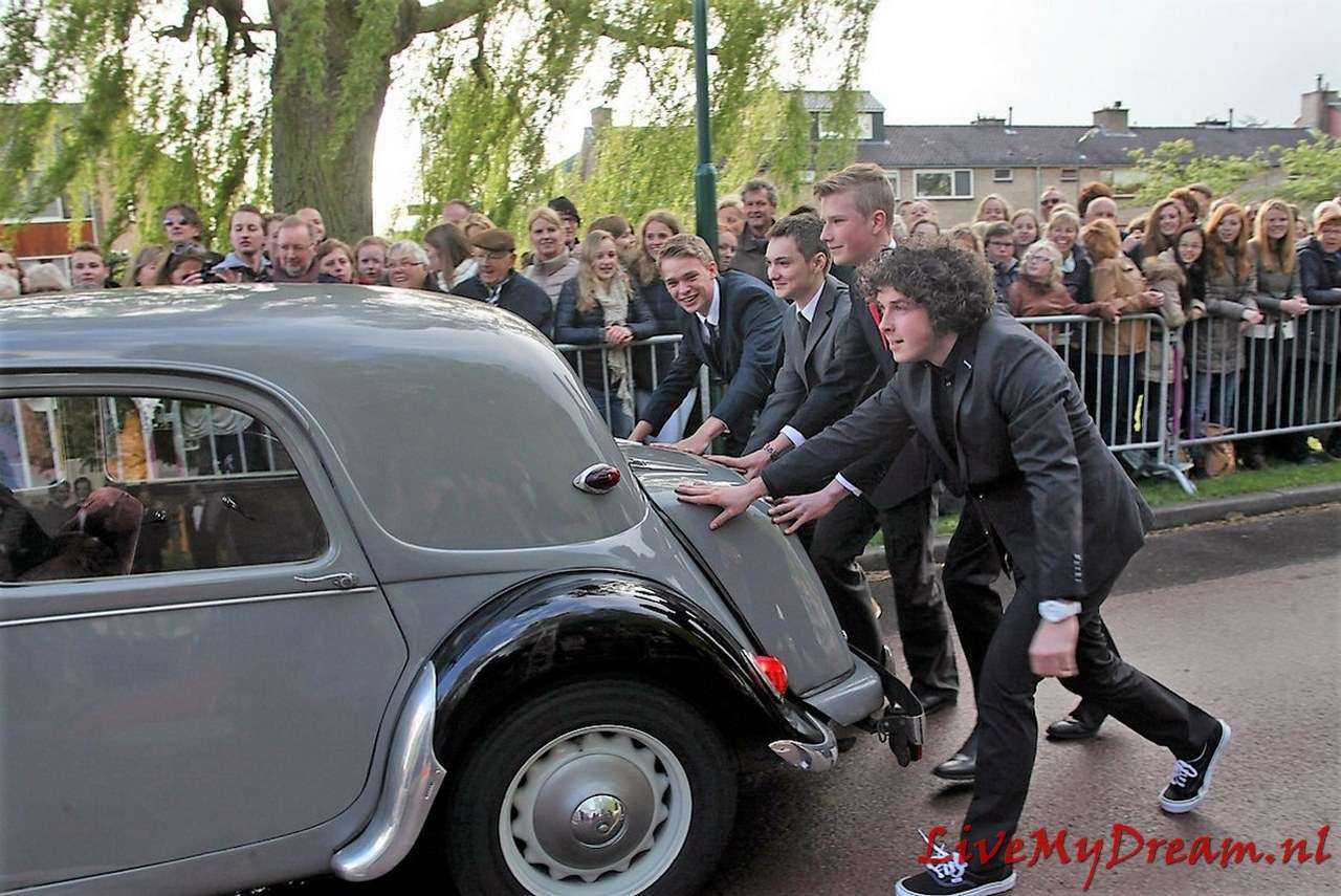
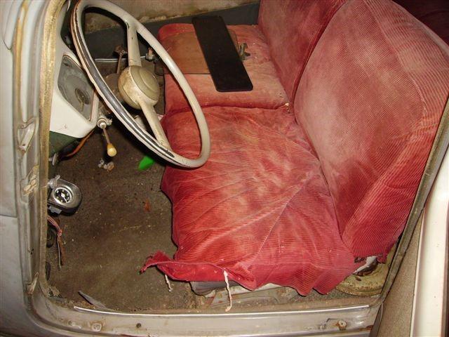
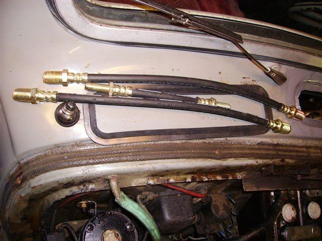
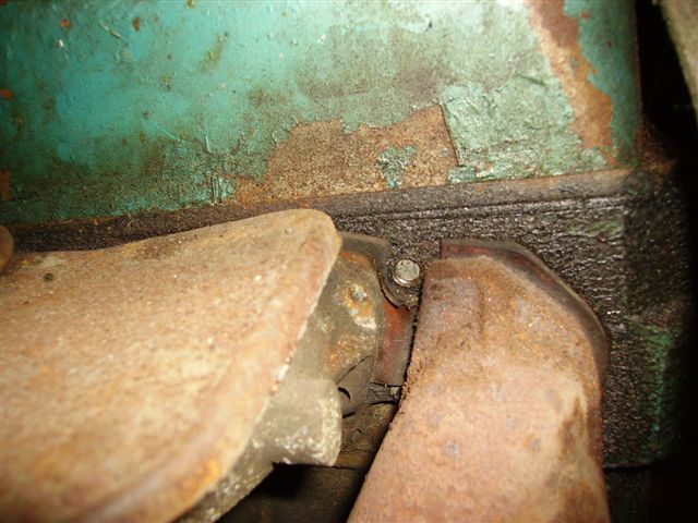
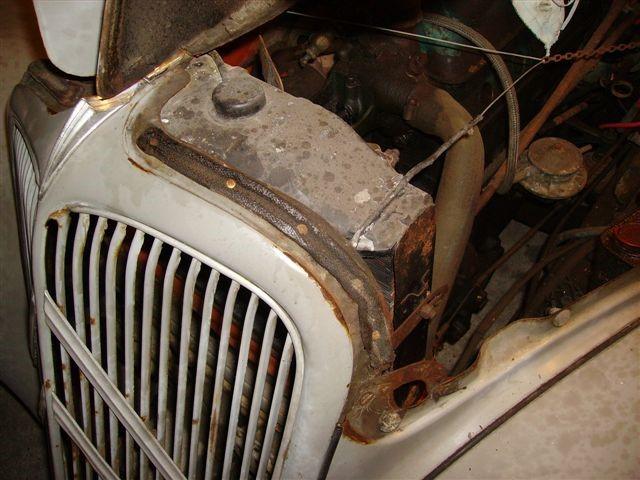
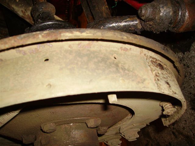
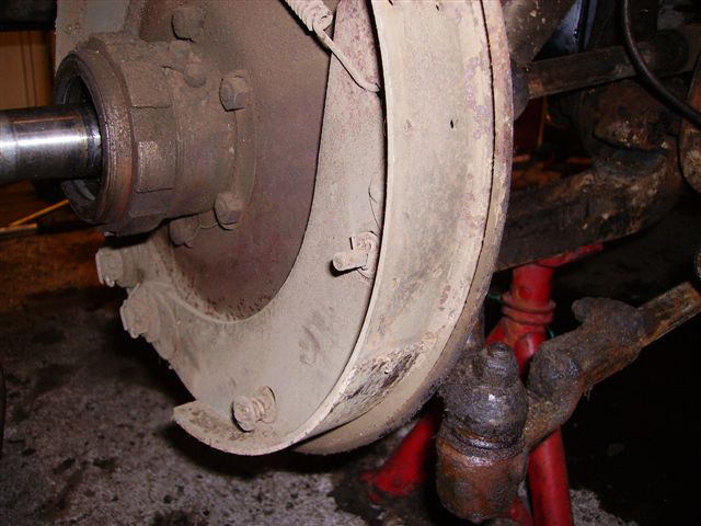
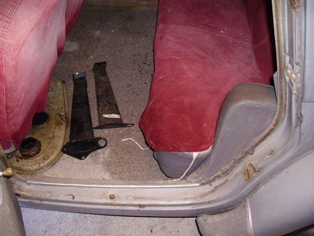
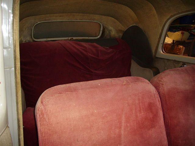
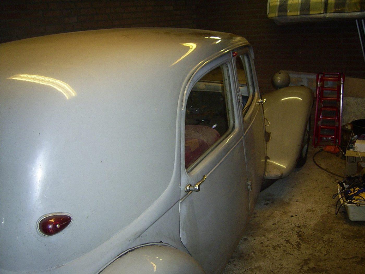
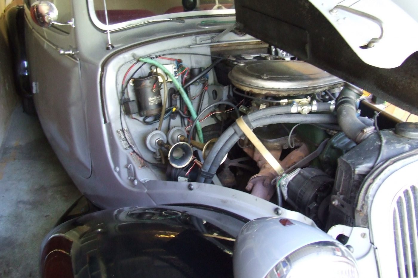
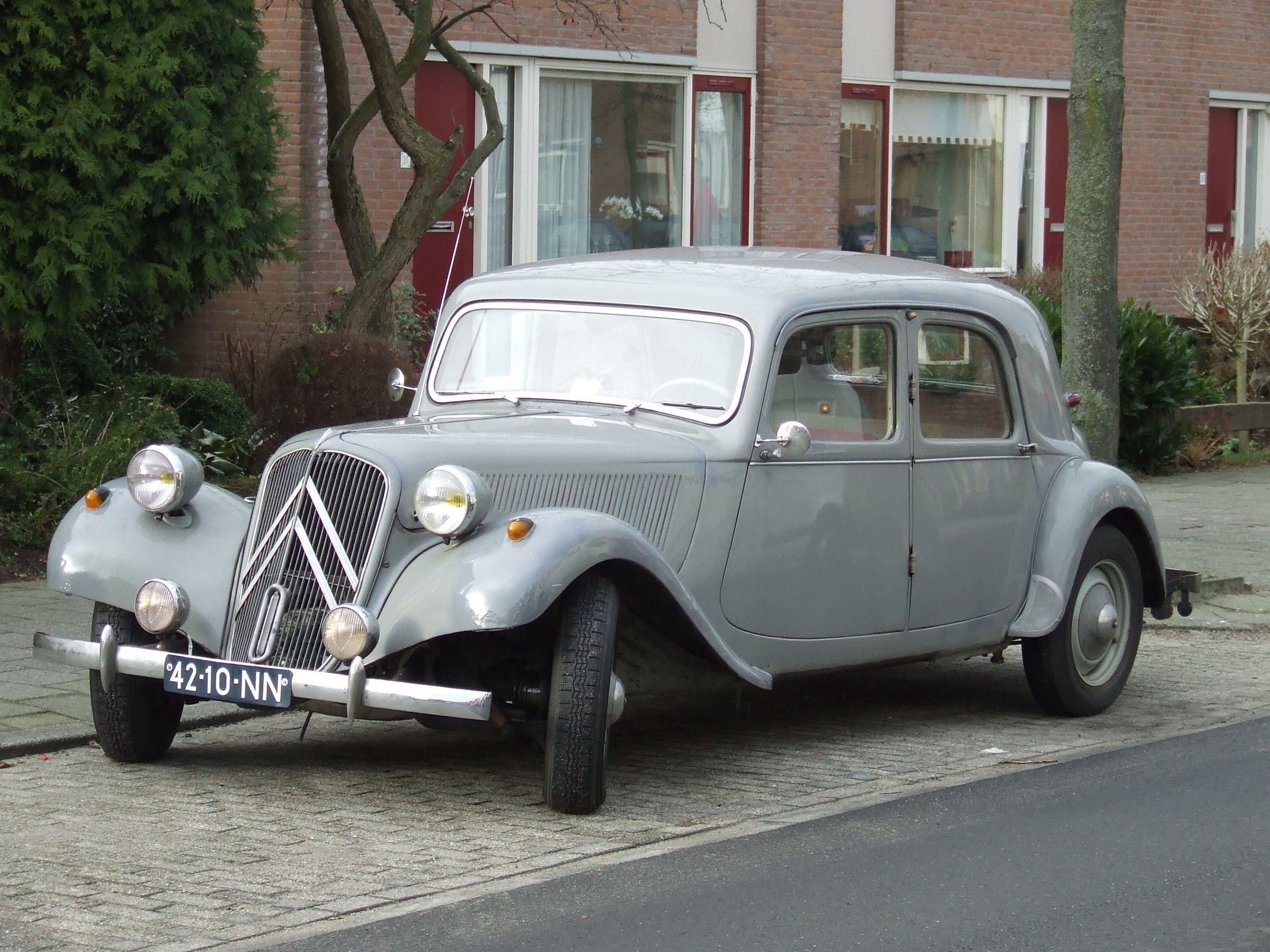
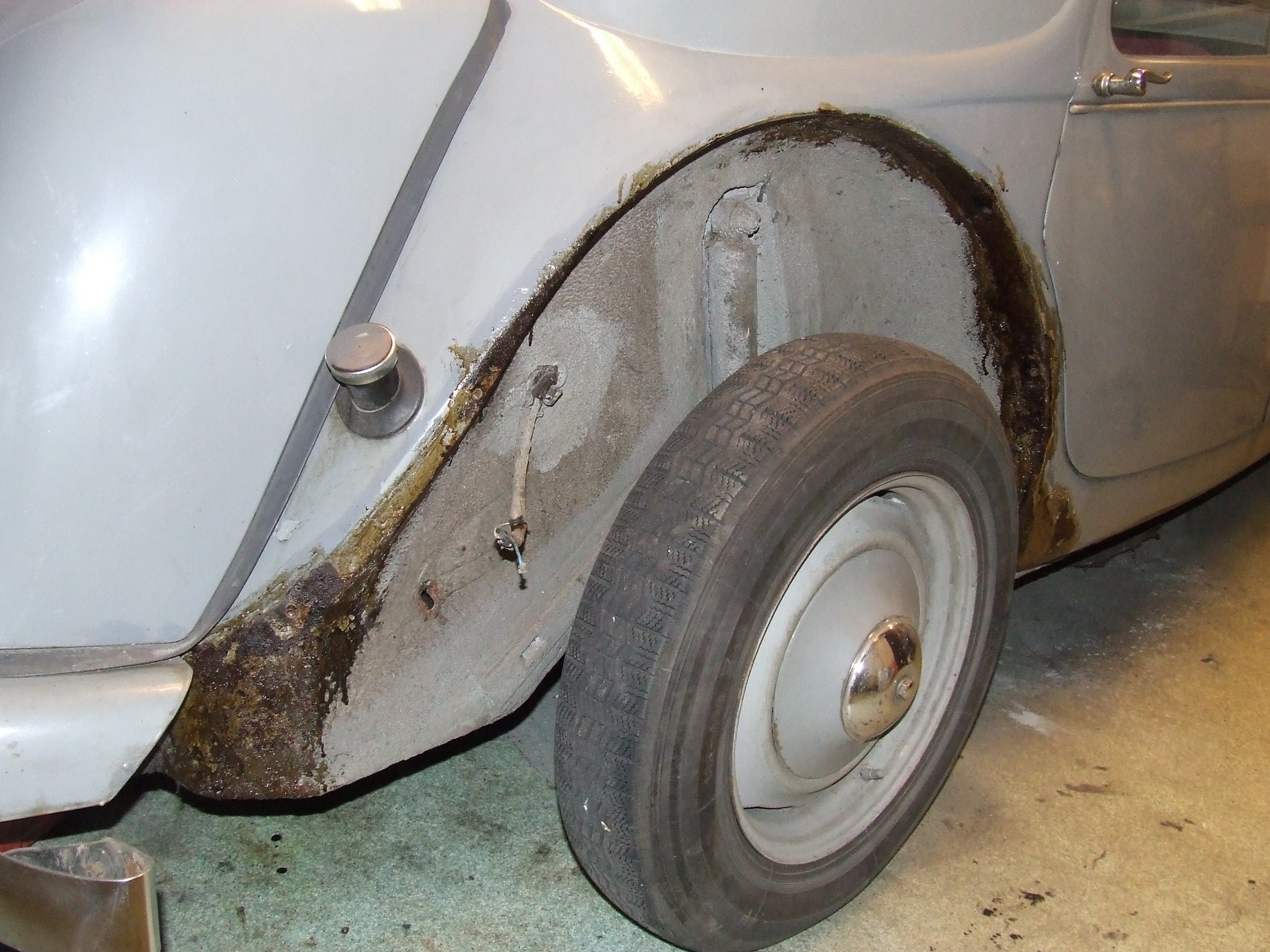
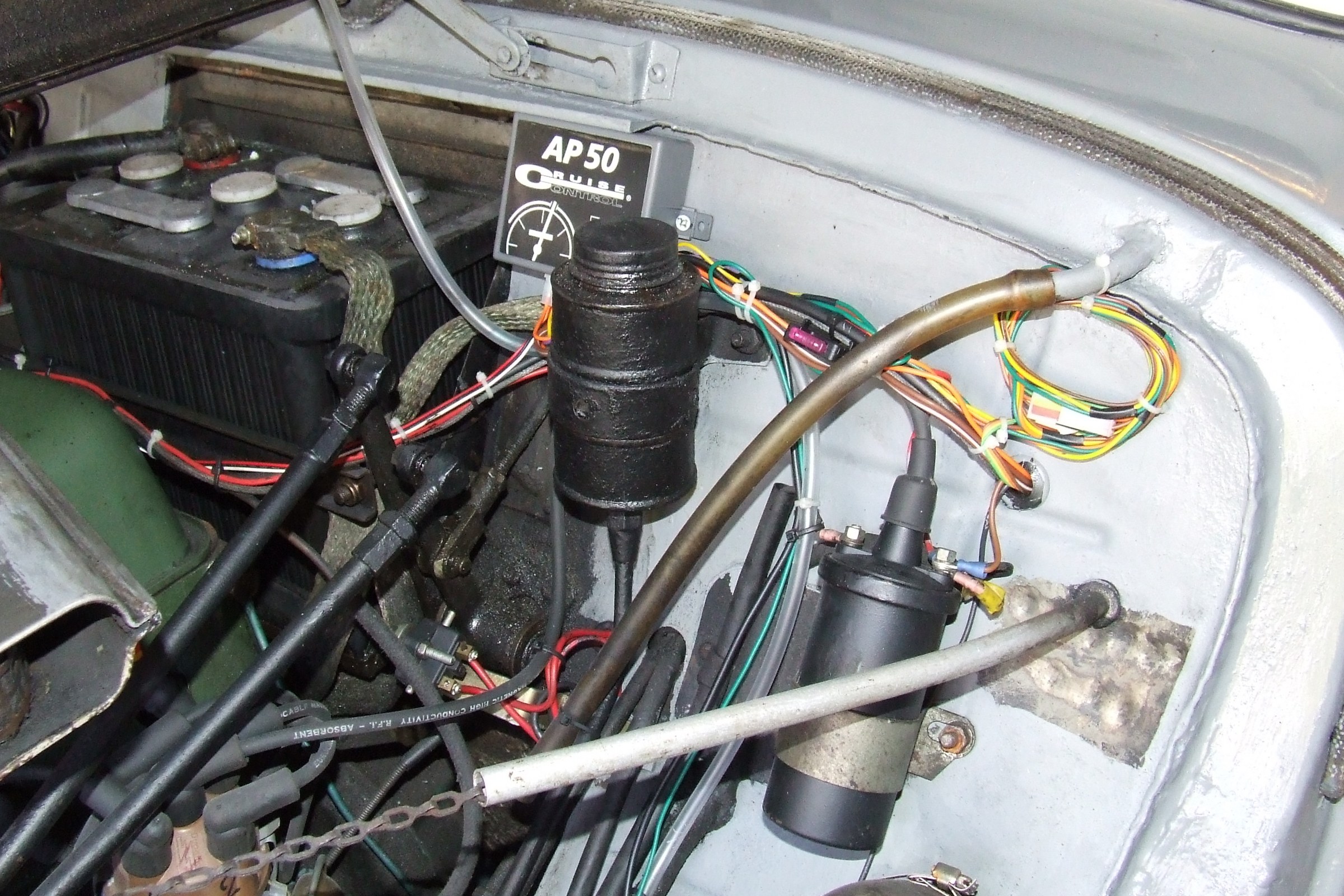
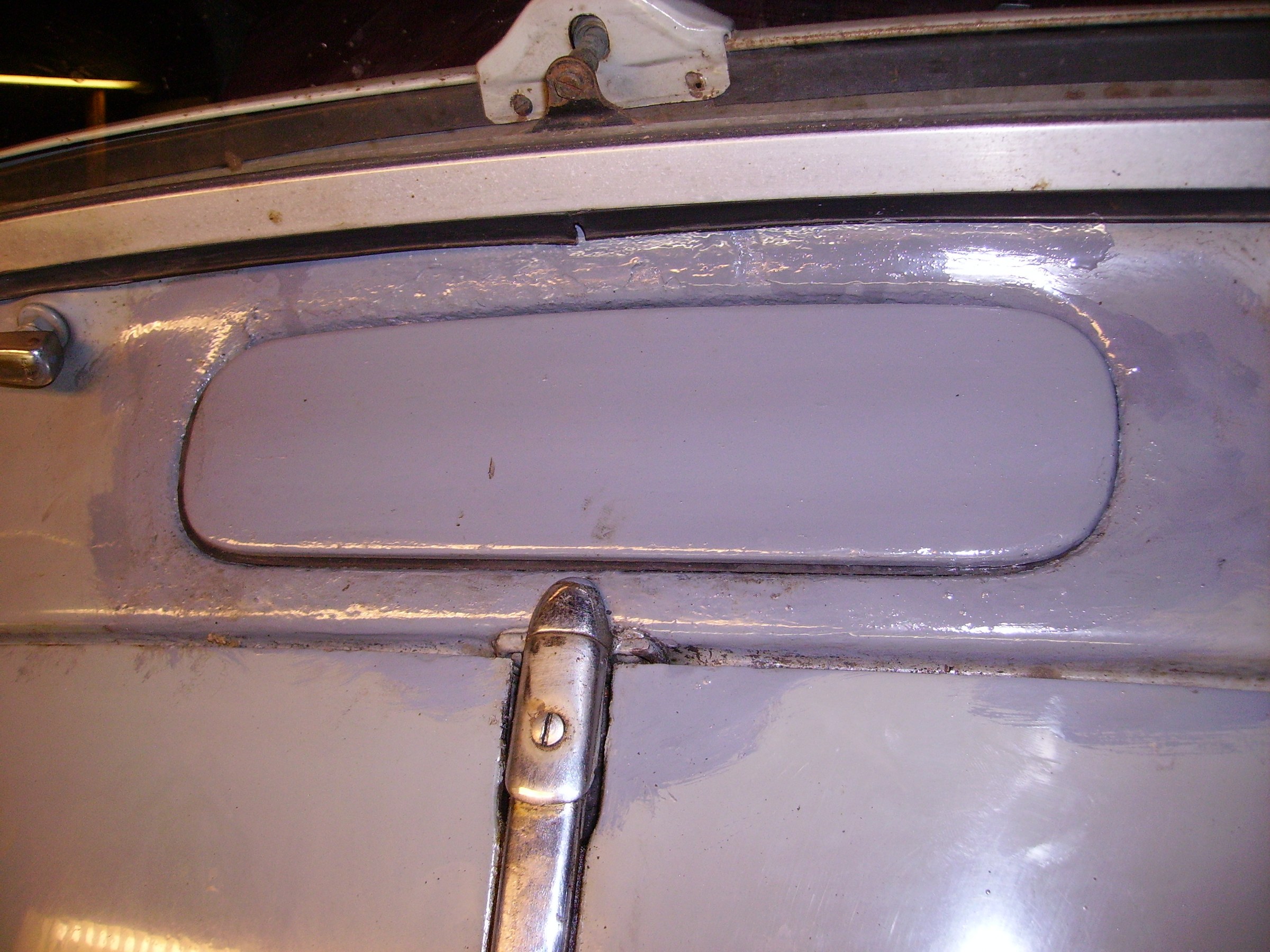
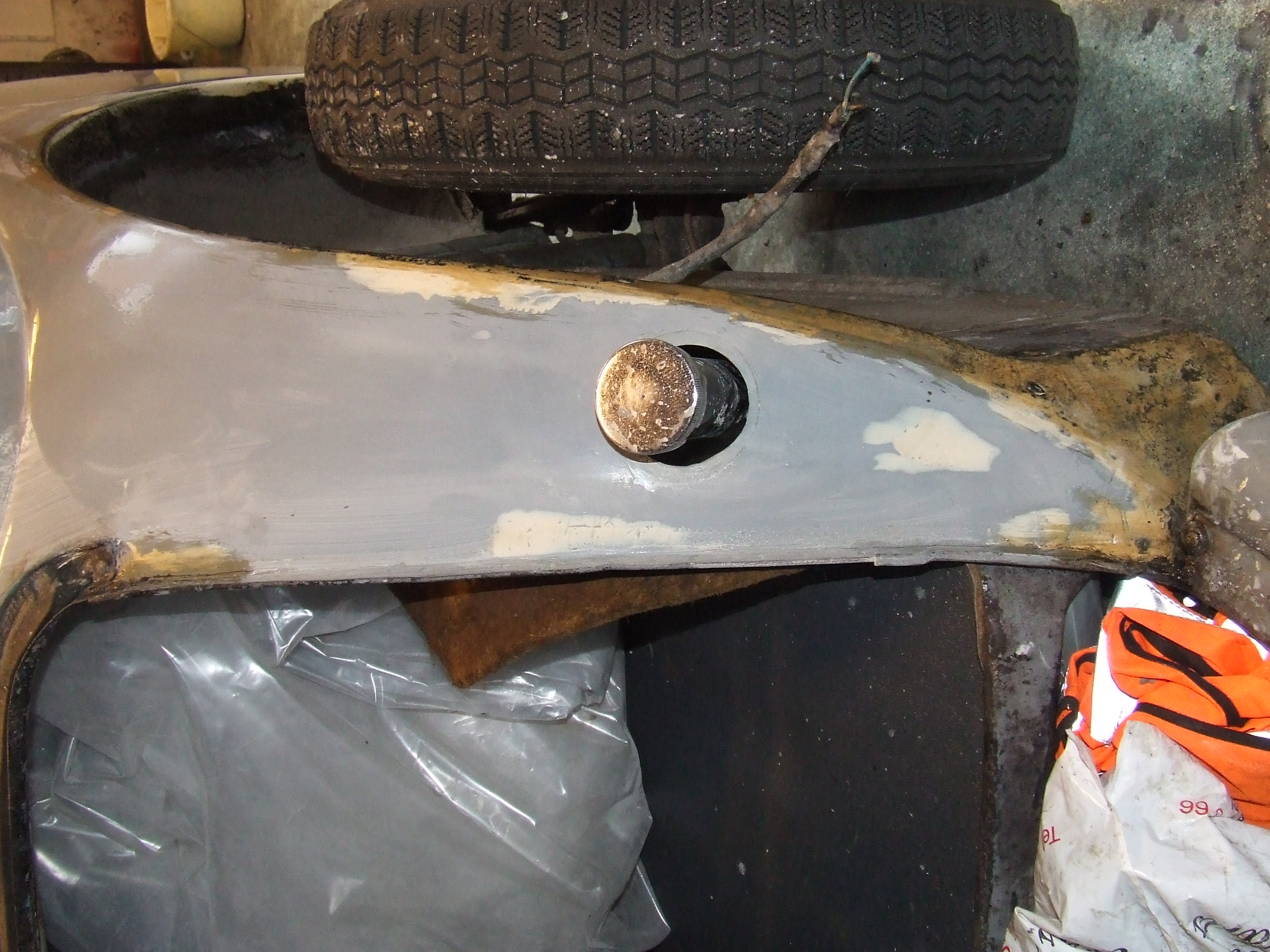
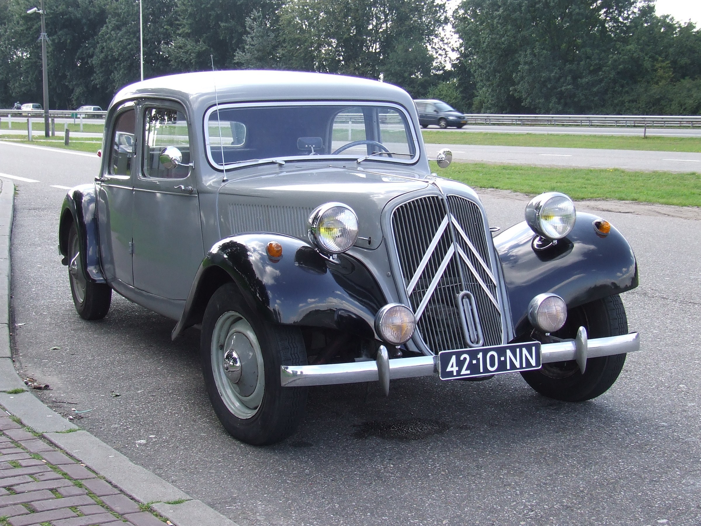
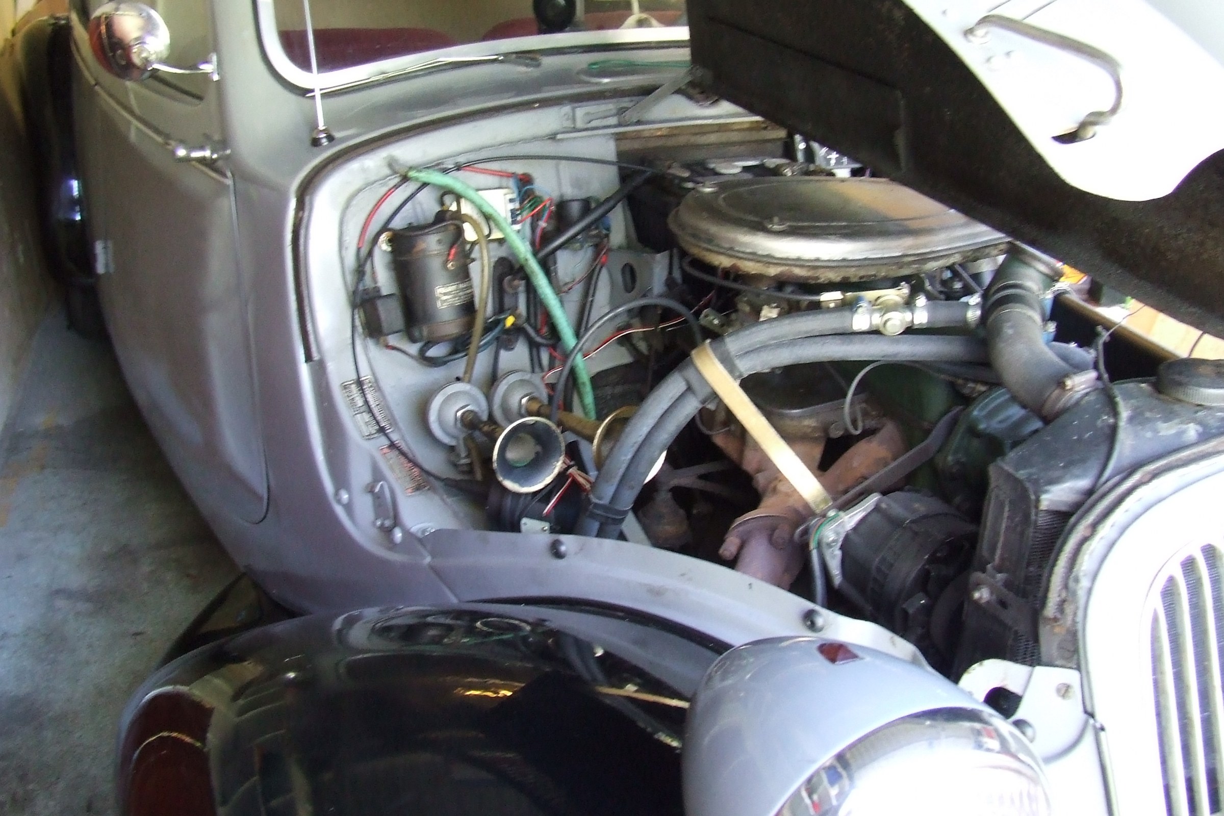
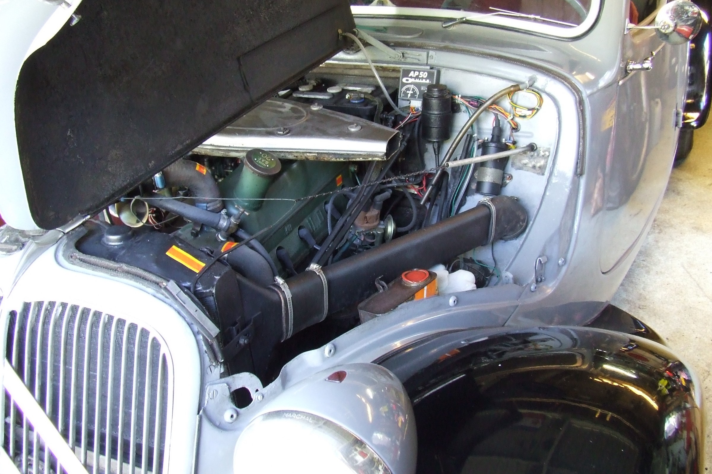
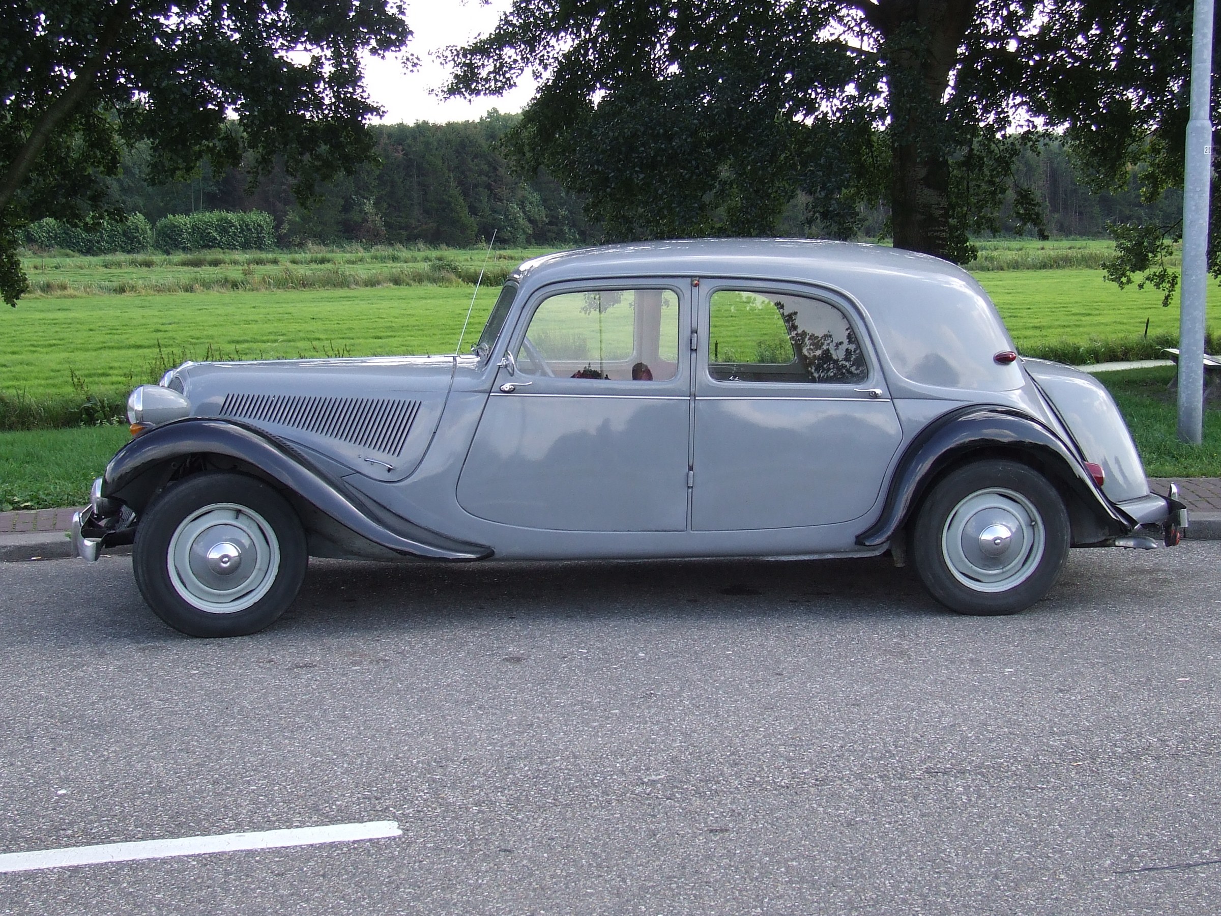
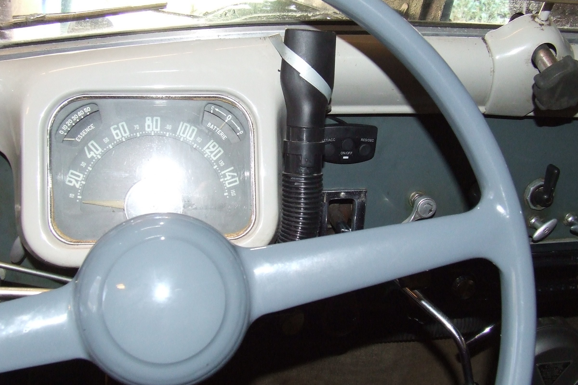
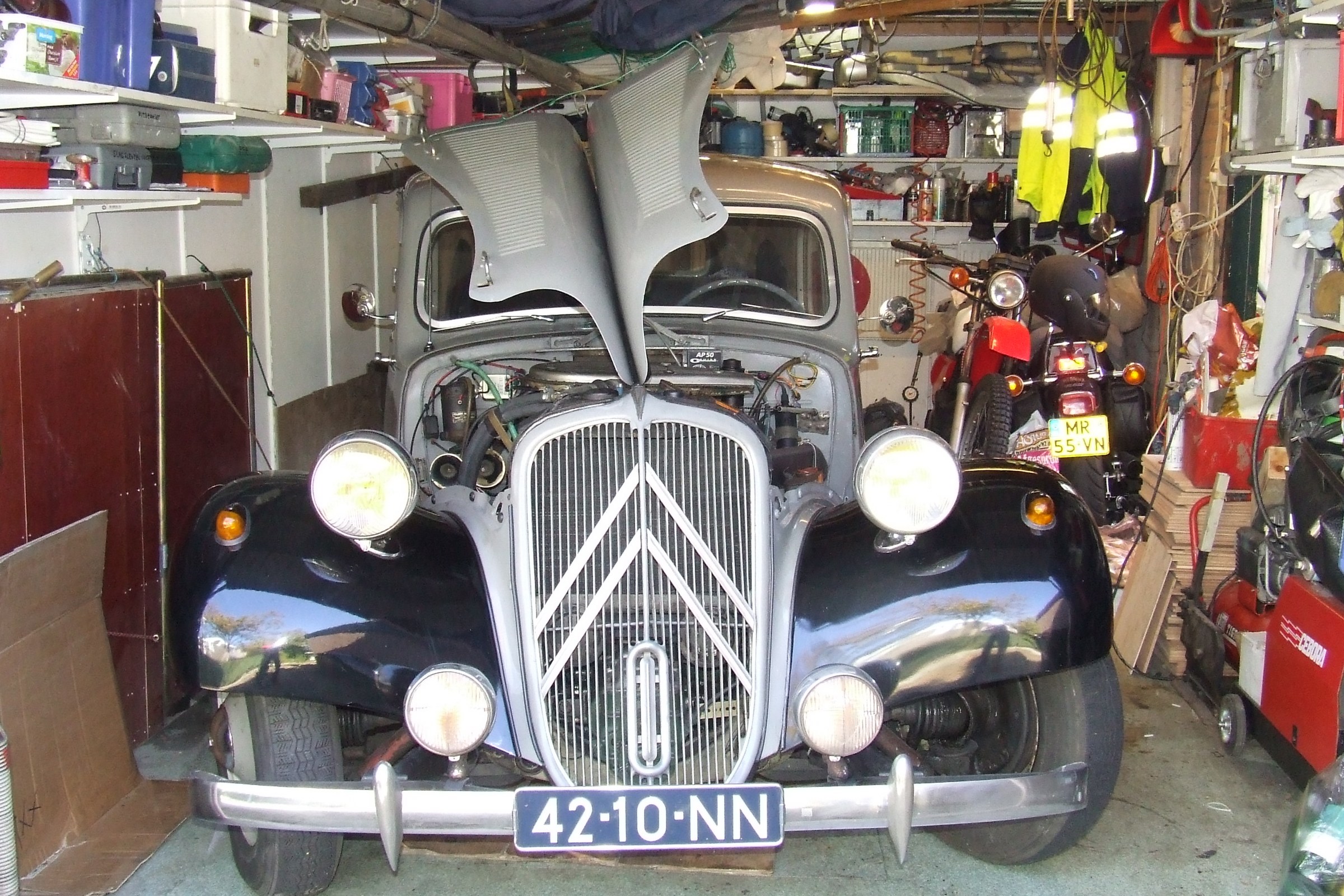
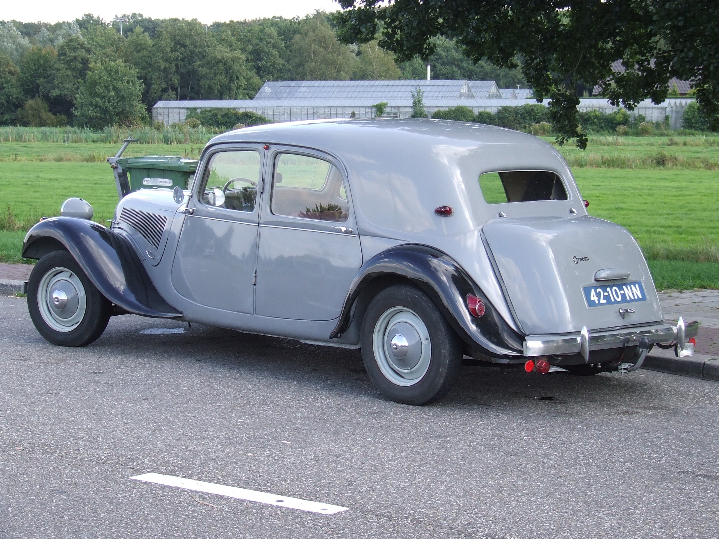
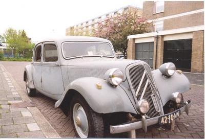
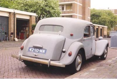
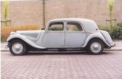
DOT3 brake fluid in my Traction Avant

The Traction Avant is regularly parked at our place for long periods of time.

Each time, the level of my brake fluid when I picked up the car was at minimum, while I had put the car away with maximum level.

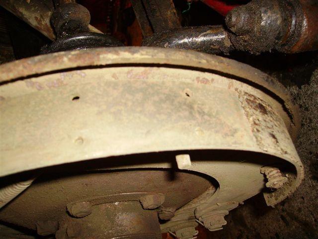
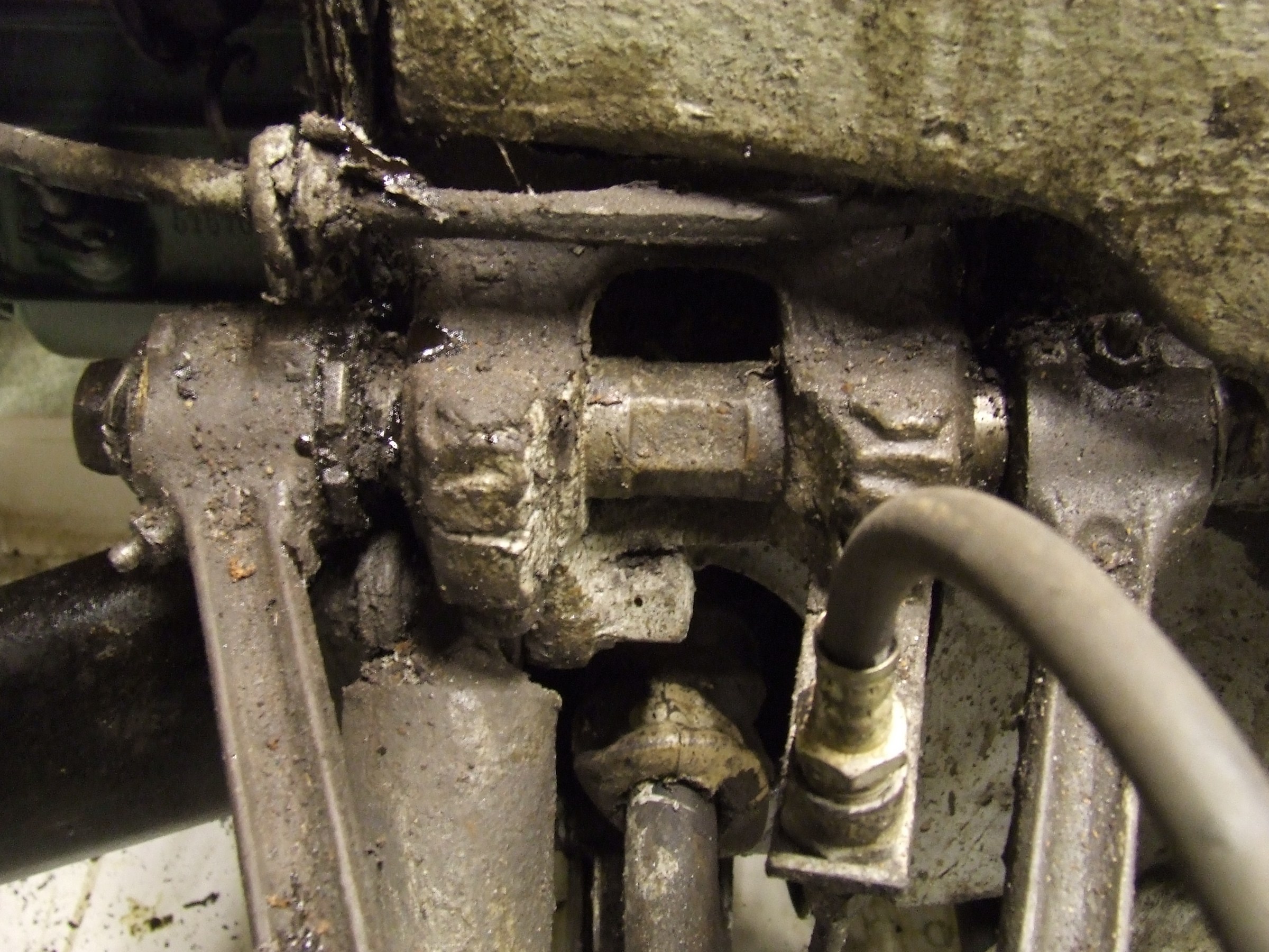
The reason turned out to be that on almost all parts where the original meager mineral brake fluid could flow under gravity along a brake cup, it actually did.

The result was a lot of filth and an empty reservoir.

The residual pressure that keeps the rubbers sealing nicely, drops off after a certain time and then this above mentioned problem arises.

The solution turned out to be upgrading to DOT3 brake fluid. DOT 3 has somewhat lubricating properties which in my experience keeps the seal between cylinder walls and brake cups closed.

I’ve been using it this way since 2015 and haven’t lost a drop of DOT3 since.

An additional advantage is that because of the lubricating effect the brake pistons no longer get stuck as a result of the long downtime during the winter, in combination with the hygroscopic effect of the old brake fluid.

It was quite a job to get the old fluid out completely, flushing with methylated spirits, blowing crosswise until all the methylated spirits were removed at each end point.

Then fill up with DOT3 and do some serious bleeding.

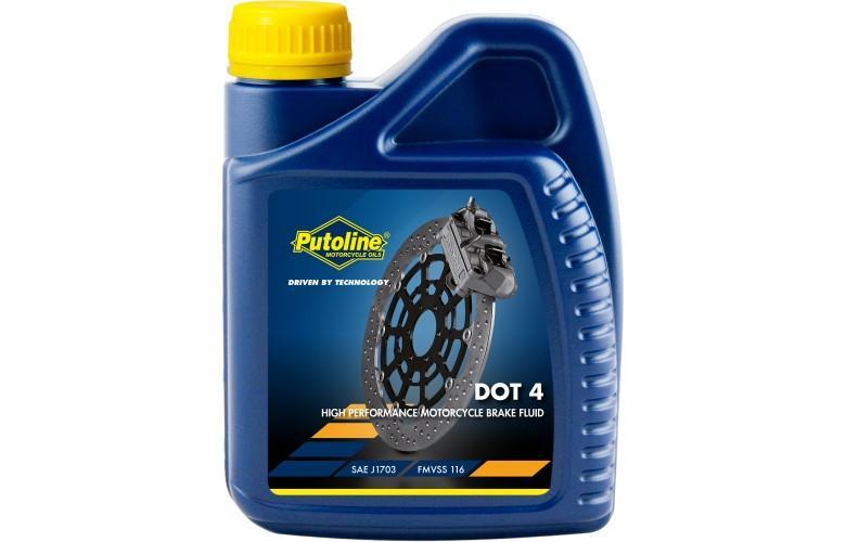
DOT 4 is not a good idea in any case, at least not with the original rubbers.

The additives in DOT4 cause the original rubbers to swell. If you want to use DOT4 or any other DOT version than DOT3, replace all rubbers and cups of the wheel brake and master cylinder with after market (so do NOT use old stock) rubbers and cups.

Good luck!

Update 3-2021: Everything is still fine with the brakes, I did remove the front brake cylinders as a precaution, cleaned them completely, flushed them out and filled them again with new DOT3.  

DOT3 OR DOT4 BRAKE FLUID

Our MOT garage, not a Mazda dealer I should mention here, exchanged the brake fluid early 2018 from the original DOT3 to DOT4, without asking us.

Almost instantly we had problems. The front disc brakes did not return after braking.

The brake pads kept in place against the discs and when driving corners you heard the pads humming.

This is caused by the additives in the Dot4 brake fluid. This fluid is much more aggressive than DOT3 fluid. No problem for modern cars. But our 2004 Mazda could not cope with DOT4.  The rubbers swoll and got thicker.  Clearly to be seen at the filler cap. Hardly impossible after a month of DOT4 to get the rubber back in.

So, although trusted websites and garages, so_alled experts advice to upgrade to DOT4, Never Ever do this. There is a reason for the message ONLY DOT3.

I have exchanged the fluid with DOT3 now, and I hope that this solves our problems. Fingers crossed..  Otherwise a complete revision of brakes and clutch is required…  4 brake calipers, 1 master brake cylinder, 1 master clutch and the clutch servo…  Not the costs, but a lot of work. Although, after this any DOT will be possible.. Hmmm. Maybe not that bad a thought after all.

If you really need to go from DOT3 to DOT4 without changing cups and rubbers, do the simple test as described below:

Take the rubber from the filler cap out, put it in a closed jar filled with fresh DOT4 for a week and fit it back in.

If it fits perfectly, go ahead with DOT4.

And the garage? They are the expert, no way they will repair our car… In their opinion the car is too old anyway and it should be EOL.

Inserted article:

3 Points To Take Note When Comparing Between DOT 3 Vs DOT 4 Brake Fluid

The brake fluid is the lifeblood of the braking system. It keeps the braking components lubricated so that they respond promptly when you press the brake pedal. With the help of the fluid, the piston can comfortably compress the rotors to slow down the vehicle. DOT 3 and DOT 4 are two most common types used in automobiles. If you are looking for the right fluid for your car, a comparison of DOT 3 vs DOT 4 brake fluid will help you to decide better.

What Is the Difference between DOT 3 vs DOT 4 Brake Fluid?

DOT 3 is the most common and popular brake fluid type of truck and cars. DOT 4 is also gaining momentum due to its compatibility with anti-lock braking system and traction control. The first one is the standard, low-cost option for average cars where there is little chance for the drivers to engage in aggressive braking actions. But, automobiles like racing cars and police vehicles that need frequent vigorous braking use DOT 4 fluid. Let’s find out some more points of difference between DOT3 vs DOT4:

dot 3 vs dot 4
A comparison will help you take a better decision.

1. Boiling Point

The major difference between DOT 3 vs DOT 4 is the boiling point – their tenacity to absorb water. DOT 3 is more prone to assimilate water because it has a lower boiling point. For this reason, it boils easily under hard and rough braking, which could ruin the braking components and cause subpar braking performance. For this reason, the DOT 4 fluid can easily replace DOT 3 but the second one should not be used as an alternative to the DOT 4 type until it’s absolutely necessary.

2. The Chemical Structure

Another slight difference between DOT 3 vs DOT 4 brake fluid is their chemical components. DOT 3 has a blend of ether and polyalkylene glycol whereas a mixture of glycol and borate creates the DOT 4 fluid. The glycol-ether blend holds very well in hot and wet conditions, which is perfect for regular vehicles where the brakes get heated up easily. On the other hand, DOT 4’s chemical ingredients that show a high level of water tolerance and stability under high temperatures.

3. Boiling Capacity

DOT 3 is the winner in this comparison section between DOT 3 vs DOT 4 brake fluid. It functions well in both water and open air because it has both wet and dry boiling capacity. DOT 4 has an excellent dry boiling capacity but it does not work well in water.

Which one should you choose? DOT 3 or DOT 4 brake fluid? Well, the first one is the best option if you are driving a standard vehicle. However, if it’s a racing car or you like rough driving, DOT 4 will take better care of the braking components.

dot 3 or dot 4 brake fluid
DOT 4 will take better care of braking parts.

Are There Any Cautions to be Aware of?

Yes, there are a few things to be aware of. Both fluid types eat paint, so don’t spill them on the car body. Also, they can react badly if mixed with other fluids used in a vehicle.

You should keep the fluids in tightly sealed containers. The moisture in the air degrades their chemical components. So, it’s not safe to use the brake fluid from an open bottle.

Soldering aluminum

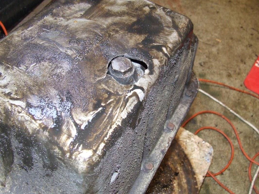
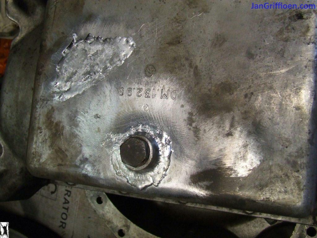
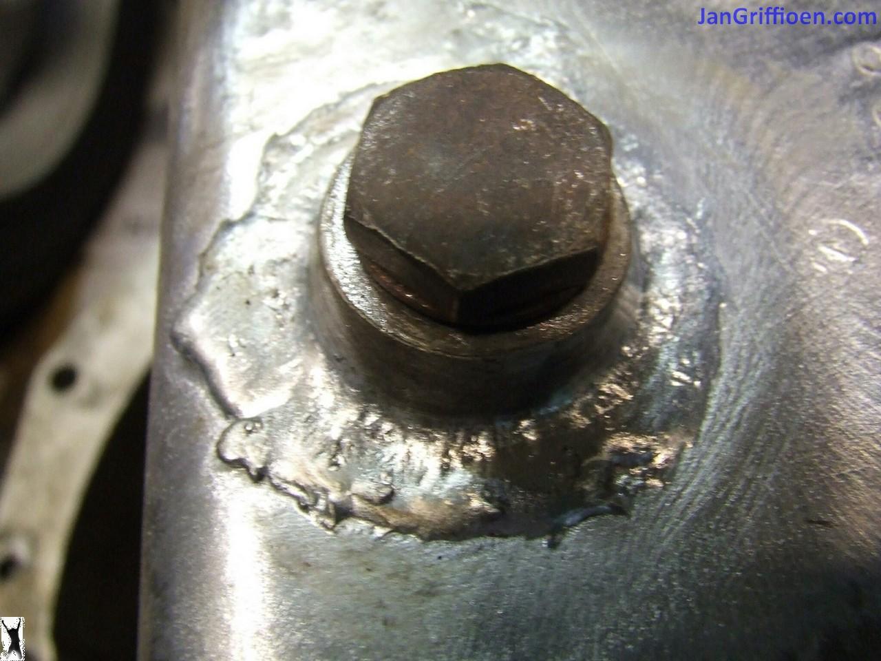
With an ordinary soldering torch you can solder aluminum with special rods, at a much lower temperature than when you can weld aluminum.  If you clean the materials with a stainless steel brush and preheat the materials well on, for example, a 4-burner stove, you can solder aluminum with an ordinary soldering torch (for tin).  I managed it and it is absolutely hard and tight!

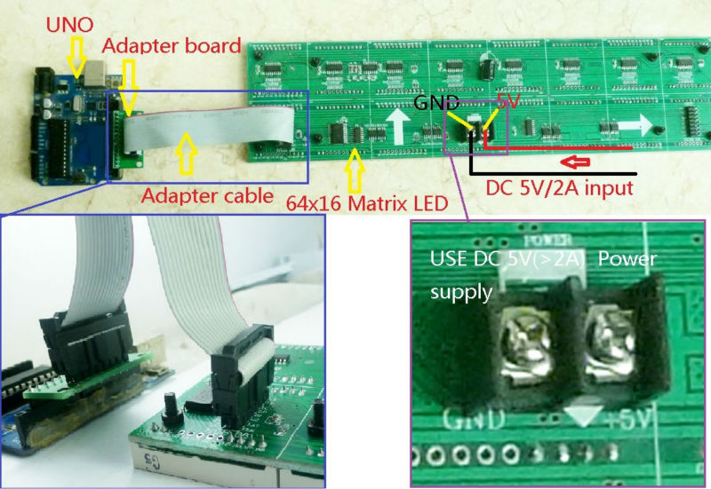
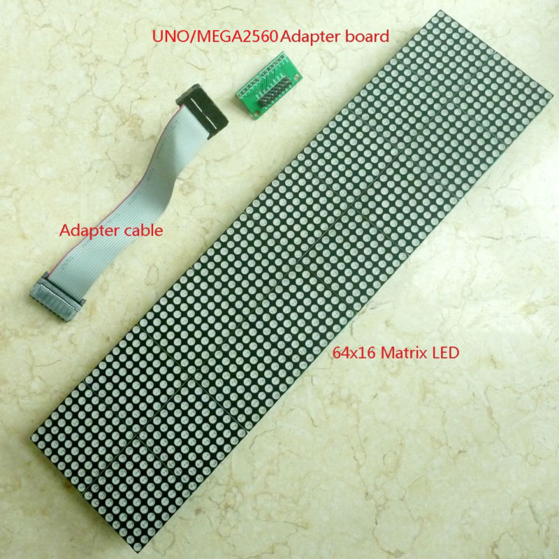
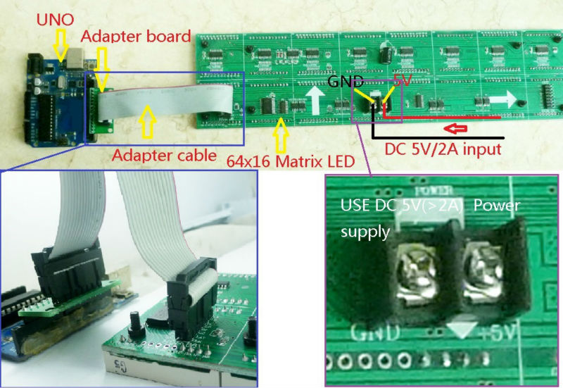
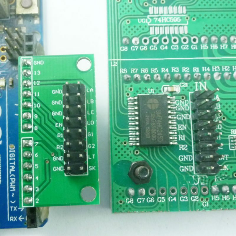
Arduino led bar demo & sketch for 64×16 Canton electronics LED matrix

Module No.:  TB275

//#include <AT24Cxx.h>//no lib needed since we will only use basic functions in 1 page at first

// Author: Phil Kaziewicz 19th July 2014,
// Jan Griffioen did quite some ADDITIONS july-nov 2014 such as RTC, temp, humidity, barmetric pressure, stringtext in time, funny roll-ups etc and voidstructuring
// 64×16 LED display matrix test code
// based upon original code from canton-electonics
// Arduino 1.0.6 NANO V4.0 (with the 2008 Windows drivers; these work with W8.1;

// add buttons or wire bridges for intensity (if possible), speed, language, time up and time down (both last buttons work more agressively when kept pushing…)
// will also try to adapt rotary switches for settings…
// D9& D?? are free for this
// A1 and A3, A6 and higher are free for this, preferrably with a resistor network like on the LCD shields, that should only consume 1 A-pin…
// Add a device for proximity and connect to a ‘button’ input for something like speed or intensity// crash,…
// The development is done with a Nano, after all is OK the pro mini will be glued to the rear of the board and one time programmed via a USB to TTL converter.
// Re-programming only on request!

#include <dht.h>

// Example testing sketch for various DHT humidity/temperature sensors
// Written by ladyada, public domain

#define DHTPIN 16 // what pin we’re connected to; A2=D16

// Uncomment whatever type you’re using!
#define DHTTYPE DHT11 // DHT 11
//#define DHTTYPE DHT22 // DHT 22 (AM2302)
//#define DHTTYPE DHT21 // DHT 21 (AM2301)

// Connect pin 1 (on the left) of the sensor to +5V
// NOTE: If using a board with 3.3V logic like an Arduino Due connect pin 1
// to 3.3V instead of 5V! with shield 5V is OK
// Connect pin 2 of the sensor to whatever your DHTPIN is
// Connect pin 4 (on the right) of the sensor to GROUND
// Connect a 10K resistor from pin 2 (data) to pin 1 (power) of the sensor

// Initialize DHT sensor for normal 16mhz Arduino
DHT dht(DHTPIN, DHTTYPE, 10);
// NOTE: For working with a faster chip, like an Arduino Due or Teensy, you
// might need to increase the threshold for cycle counts considered a 1 or 0.
// You can do this by passing a 3rd parameter for this threshold. It’s a bit
// of fiddling to find the right value, but in general the faster the CPU the
// higher the value. The default for a 16mhz AVR is a value of 6. For an
// Arduino Due that runs at 84mhz a value of 30 works.
// Example to initialize DHT sensor for Arduino Due:
//DHT dht(DHTPIN, DHTTYPE, 30);

//inputs for the select switches are: A1= Select, D9= Up and D7= Down

#define SelectPIN 15 //(=A1 when used digital) // what pin we’re connected to input for the select switch: A1= Select
#define UpPIN 9 // what pin we’re connected to input for the select switch: D9= Up
#define DownPIN 7 // what pin we’re connected to input for the select switch: D7= Down

#include <avr/pgmspace.h>
#include <Wire.h>
byte high = 0x00, low=0x00;//used for the AT24C32 chip addressing, no lib needed here
#include “RTClib.h”

RTC_DS1307 rtc; // this time module 1307 is connected to SCL (A5 on Nano) and SDA (A4 on Nano)
//#define AT24C32 0x50 //no lib needed here , address is correct though

boolean (Select)=false;
boolean (Up)=false;
boolean (Down)=false;
boolean (DEBUG)=true;

#define BMP085_ADDRESS 0x77 // I2C address of barometer BMP085 for barometer/temp/hight; this is also connected to SCL (A5 on Nano) and SDA (A4 on Nano)

const unsigned char OSS = 0; // Oversampling Setting

// Calibration values
int ac1;
int ac2;
int ac3;
unsigned int ac4;
unsigned int ac5;
unsigned int ac6;
int b1;
int b2;
int mb;
int mc;
int md;

//int wait; //, integer between 7 and 18, memory chip position low 1 and 2
int typeofclock; //, small clock or big clock 0 or 1 position low 3
int fun; //, with fun or just readouts 0 or 1 position low 3
int minormax; //, minimum screen or all of it 0 or 1 position low 4
int matrixwidth = 64;
int matrixheight = 16;

// b5 is calculated in bmp085GetTemperature(…), this variable is also used in bmp085GetPressure(…)
// so …Temperature(…) must be called before …Pressure(…).
long b5;

// Connections to board
const byte latchPin = 8;
const byte clockPin = 12;
const byte data_R1 = 10;
const byte data_R2 = 11;
const byte en_74138 = 2;
const byte la_74138 = 3;
const byte lb_74138 = 4;
const byte lc_74138 = 5;
const byte ld_74138 = 6;
byte ScanRow = 0;
unsigned long counter;
const int pinRandom = A0; // better to get this than use the standard C randomizer.. A0 can be freed if needed for anything else….

//const int wait = 100; // In milliseconds
const int length = 8;
int x[length], y[length];
int ptr, nextPtr;
int wait = 12; // In milliseconds (15 is nice), must be between 8 and 18
//int inc = -1;
int resetcounter=1;
//int waittemp = 15;

// declare the strings:
//String Shour,Shour1,Sminute,SdayOfWeek,Sday,Smonth,Sdate,Syear,ENtijd,Sminutesingle,Stotal;

/* #######################################
# RTC_DS1307 Datatypes (KEYWORD1)
#######################################

DateTime KEYWORD1
RTC_DS1307 KEYWORD1
RTC_Millis KEYWORD1

#######################################
# Methods and Functions (KEYWORD2)
#######################################

year KEYWORD2
month KEYWORD2
day KEYWORD2
hour KEYWORD2
minute KEYWORD2
second KEYWORD2
dayOfWeek KEYWORD2
secondstime KEYWORD2
unixtime KEYWORD2
begin KEYWORD2
adjust KEYWORD2
isrunning KEYWORD2
now KEYWORD2

#######################################
# Constants (LITERAL1)
#######################################
*/

char* dayNameEN[] = {
“g “, “Monday”, “Tuesday”, “Wednesday”, “Thursday”, “Friday”, “Saturday”, “Sunday”};
char* hourNameEN[] = {“twelve”, “one”, “two”, “three”, “four”, “five”, “six”, “seven”, “eight”, “nine”, “ten”, “eleven”, “twelve”, “one”};
// “two”, “three”, “four”, “five”, “six”, “seven”, “eight”, “nine”, “ten”, “eleven”, “twelve”};
char* monthNameEN[] = {“G “, ” January”, “February”, “March”, “April”, “May”, “June”, “July”, “August”, “September”, “October”, “November”, “December”};

byte buffer[256] = { // Display buffer (which is scanned by the interrupt timer) of 8×32 bytes
0x00, 0x00, 0x00, 0x00, 0x00, 0x00, 0x00, 0x00, 0x00, 0x00, 0x00, 0x00, 0x00, 0x00, 0x00, 0x00,
};

#include <fontsBIGREDLED.h>

// xxxxxxxxxxxxxxxxxxxxxxxxxxxxxxxxxxxxxxxxxxxxxxxxxxxxxxxxxxxxxxxxxxxxxxxxxxxxxxxxxxxxxxxxxxxxxxxxxxxxxxxxxxxxxxxxxxxxxxx
// Routine to print a single character in one of 8 columns
// Inputs:
// x is one of (0,16,24,32,40,48,56), for shifting purposes 64 should als be available….
// y (0 to 16 or 24 depending upon font size),
// n is either (0 to 9) or an ascii value, ascii as ([“”])??
// font=0 for big font, 2 for small font,
// inverse is true for an inverted character
void drawChar(uint16_t x, uint16_t y, byte n, byte font, boolean inverse) {
byte charbytes[16], fontrows, xover8 = x >> 3;
int index;
if (0 != (x % 8)) return; // x not a multiple of 8
if ((n > 9) && (n < 32)) return; // invalid character
if (font == 2) fontrows = 16; else fontrows = 8;
if ((n >= 0) && (n <= 9)) index = (n + 16) * fontrows; else index = (n – 32) * fontrows; // go to the right code for this character

// addressing start at buffer and add y (rows) * (WIDTH is 64 so WIDTH/8) is 8 plus (x / 8) is 0 to 7
byte *pDst = buffer + (y << 3) + xover8;
for (byte i = 0; i < fontrows; i++) { // fill up the charbytes array with the right bits
if (font == 0) charbytes[i] = pgm_read_byte(&(font8x8_basic[index + i]));
// if (font==1) charbytes[i] = pgm_read_byte(&(font8x8_extended[index+i]));
if (font == 2) charbytes[i] = pgm_read_byte(&(font8x16_basic[index + i]));
// reverse bit order for fonts 0 and 1
if (font != 2) {
charbytes[i] = (charbytes[i] & 0xF0) >> 4 | (charbytes[i] & 0x0F) << 4;
charbytes[i] = (charbytes[i] & 0xCC) >> 2 | (charbytes[i] & 0x33) << 2;
charbytes[i] = (charbytes[i] & 0xAA) >> 1 | (charbytes[i] & 0x55) << 1;
};
if (inverse) charbytes[i] = ~charbytes[i];
};
const byte *pSrc = charbytes; // point at the first set of 8 pixels
for (byte i = 0; i < fontrows; i++) {
*pDst = *pSrc; // populate the destination byte
pDst += 8; // go to next row on buffer
pSrc++; // go to next set of 8 pixels in character
}
};
// xxxxxxxxxxxxxxxxxxxxxxxxxxxxxxxxxxxxxxxxxxxxxxxxxxxxxxxxxxxxxxxxxxxxxxxxxxxxxxxxxxxxxxxxxxxxxxxxxxxxxxxxxxxxxxxxxxxxxxx
void moveLeft(byte pixels, byte rowstart, byte rowstop) { // routine to move certain rows on the screen “pixels” pixels to the left
byte row, column;
short unsigned int address;
for (column = 0; column < 8; column++) {
for (row = rowstart; row < rowstop; row++) {
address = (row << 3) + column; /// right here!
if (column == 7)
buffer[address] = buffer[address] << pixels; // shuffle pixels left on last column and fill with a blank
else { // shuffle pixels left and add leftmost pixels from next column
byte incomingchar = buffer[address + 1];
buffer[address] = buffer[address] << pixels;
for (byte x = 0; x < pixels; x++) {
buffer[address] += ((incomingchar & (128 >> x)) >> (7 – x)) << (pixels – x – 1);
};
}
}
}
};
// xxxxxxxxxxxxxxxxxxxxxxxxxxxxxxxxxxxxxxxxxxxxxxxxxxxxxxxxxxxxxxxxxxxxxxxxxxxxxxxxxxxxxxxxxxxxxxxxxxxxxxxxxxxxxxxxxxxxxxx
// set a single pixel on or off
void setPixel(byte x, byte y, byte colour) {
bitWrite(buffer[(y << 3) + (x >> 3)], 7 – (x & 7), colour);
};
// xxxxxxxxxxxxxxxxxxxxxxxxxxxxxxxxxxxxxxxxxxxxxxxxxxxxxxxxxxxxxxxxxxxxxxxxxxxxxxxxxxxxxxxxxxxxxxxxxxxxxxxxxxxxxxxxxxxxxxx
void drawRect(byte x1, byte y1, byte x2, byte y2, byte colour) {
for (byte x = x1; x <= x2; x++) {
setPixel(x, y1, colour);
setPixel(x, y2, colour);
};
for (byte y = y1; y <= y2; y++) {
setPixel(x1, y, colour);
setPixel(x2, y, colour);
};
};

//start VOID =====================================================================================
void drawLine(byte x1, byte y1, byte x2, byte y2, byte colour) {

//Draws a line, between the points (x1, y1) and (x2, y2) in this graphics context’s coordinate system.
//Parameters:
// x1 – the first point’s x coordinate.
// y1 – the first point’s y coordinate.
// x2 – the second point’s x coordinate.
// y2 – the second point’s y coordinate.

for (byte x = x1; x <= x2; x++) {
setPixel(x, y1, colour);
setPixel(x, y2, colour);
};
for (byte y = y1; y <= y2; y++) {
setPixel(x1, y, colour);
setPixel(x2, y, colour);
};
};

// xxxxxxxxxxxxxxxxxxxxxxxxxxxxxxxxxxxxxxxxxxxxxxxxxxxxxxxxxxxxxxxxxxxxxxxxxxxxxxxxxxxxxxxxxxxxxxxxxxxxxxxxxxxxxxxxxxxxxxx
void shiftOut(byte row) { // fast routine to shove out 8 columns into two rows via board’s shift registers
for (byte column = 0; column < 8; column++) {
byte index = column + (row << 3);
for (byte i = 0; i < 8; i++) {
PORTB &= ~(3 << (data_R1 – 8)); // data_R2 is LOW; data_R1 is LOW;
PORTB &= ~(1 << (clockPin – 8)); // digitalWrite(clockPin,LOW);
PORTB |= !((buffer[index] >> (7 – i)) & 0x01) << (data_R1 – 8); // top set of rows
PORTB |= !((buffer[index + 128] >> (7 – i)) & 0x01) << (data_R2 – 8); // bottom set of rows
PORTB |= 1 << (clockPin – 8); // digitalWrite(clockPin,HIGH);
};
};
};

// Scan a pair of rows on to the display from “buffer” via the interrupt
ISR(TIMER2_COMPA_vect) {
cli();
digitalWrite(en_74138, HIGH); // Turn off display
shiftOut(ScanRow); // Shift out 8 columns
digitalWrite(latchPin, LOW);
digitalWrite(latchPin, HIGH);
PORTD = (ScanRow << 3) | (PORTD & 0X87); // Highlight row: pins 3 4 5 6 (la_74138 lb_74138 lc_74138 ld_74138)
digitalWrite(en_74138, LOW); // Turn on display
ScanRow++; // Do the next pair of rows next time this routine is called
if (ScanRow == 16) ScanRow = 0;
sei();
};

//start VOID =====================================================================================
void wacht(int wachttijd)
{
for (int a = 0; a < wachttijd; a++ )
{
int val = digitalRead(SelectPIN); // must be Select read the input pin

if (val==LOW) // if key Select is pressed
{
Select=true; // set a binary state high here , then
return; //return to loop;
}

delay(1);
}
}

//======================================================================================================================================================
//void(* resetFunc) (void) = 0;//declare reset function at address 0

//======================================================================================================================================================
void runscreen(String Stotal)
{
int stringlength= (Stotal.length()+1);//+1
char timestring[stringlength];
Stotal.toCharArray(timestring,(stringlength));
static int count = 0;

for (int count = 0; count <= sizeof(timestring) -2; count++)//was timestring-1 but then there is 1 blank space in front of each roll
{
drawChar(56, 0, timestring[count % (sizeof(timestring)-1 )], 2, false);//timestring-1
// drawChar(56, 8, timestring[count % (sizeof(timestring)-1 )], 0, false);//timestring-1
for (byte i = 0; i < 9; i++)// move the text 9 pixels (not 8 because it looks better) to the left
{
moveLeft(1, 2, 32);
wacht(wait);
}
}
}
//XXXXXXXXXXXXXXXXXXXXXXXXXXXXXXXXXXXXXXXXXXXXXXXXXXXXXXXXXXXXXXXXXXXXXXXXXXXXXXXXXXXXXXXXXXXXXXXXXXXXXXXXXXXXXXXXXXXXXXXXXXXXXXXXXXXXXXXXXXXXX
void writescreensmall(String above, String under, int height)
{
char letter;
int aa;
int a;
for (a = 0; a < 8; a++ )
{letter = above.charAt(a);
aa=8*a;
drawChar(aa, height, (letter), 0, false);
}
for (a = 0; a < 8; a++ )
{letter = under.charAt(a);
aa=8*a;
drawChar(aa, 8, (letter), 0, false);
}
}

//XXXXXXXXXXXXXXXXXXXXXXXXXXXXXXXXXXXXXXXXXXXXXXXXXXXXXXXXXXXXXXXXXXXXXXXXXXXXXXXXXXXXXXXXXXXXXXXXXXXXXXXXXXXXXXXXXXXXXXXXXXXXXXXXXXXXXXXXXXXXX
void writescreenbig(String above, int height)
{
char letter;
int aa;
int a;
for (a = 0; a < 8; a++ )
{letter = above.charAt(a);
aa=8*a;
drawChar(aa, height, (letter), 2, false);
}
}
//XXXXXXXXXXXXXXXXXXXXXXXXXXXXXXXXXXXXXXXXXXXXXXXXXXXXXXXXXXXXXXXXXXXXXXXXXXXXXXXXXXXXXXXXXXXXXXXXXXXXXXXXXXXXXXXXXXXXXXXXXXXXXXXXXXXXXXXXXXXXXXXX
void setup() {
if (Select)switches() ; // if key select is pressed it is detected in void wait and returned to loop; from there to void switches…
pinMode(SelectPIN, INPUT); // N.O. push button switch
pinMode(UpPIN, INPUT); // N.O. push button switch
pinMode(DownPIN, INPUT); // N.O. push button switch

digitalWrite(SelectPIN, HIGH); // pull-ups on
digitalWrite(UpPIN, HIGH);// pull-ups on
digitalWrite(DownPIN, HIGH); // pull-ups on

Serial.begin(9600);
// InitDHT();//Does what’s necessary to prepare for reading DHT
dht.begin();
//delay(1300); // needed for DHT11

#ifdef AVR
Wire.begin();
#else
Wire1.begin(); // Shield I2C pins connect to alt I2C bus on Arduino Due
#endif
rtc.begin();

if (! rtc.isrunning()) {
//Serial.println(“RTC is NOT running!”);
// following line sets the RTC to the date & time this sketch was compiled
rtc.adjust(DateTime(__DATE__, __TIME__));
}
// rtc.adjust(DateTime(__DATE__, __TIME__)); // Q&D way to set the time anyway but take it off the program afterwards!

for ( int ptr = 0; ptr < length; ptr++ ) {
x[ptr] = 16 ; //numberOfHorizontal8bitsDisplays * 8 / 2
y[ptr] = 16 ; //numberOfVertical8bitsDisplays * 8 / 2
}
nextPtr = 0;
// Serial.println(“Humidity and temperature\n\n”);

bmp085Calibration();

// Set up Timer2 as the scanning interrupt timer
cli(); // clear interrupts
TCCR2A = 0; TCCR2B = 0; TCNT2 = 0;
TCCR2B |= (1 << CS12) | (1 << CS10); // Set 1024 prescaler
// 160Hz scan rate = 10 frames/second (16 pairs of rows)
OCR2A = 97; // 97 = (16,000,000 / (1024*160)) – 1
TCCR2A |= (1 << WGM21); TIMSK2 |= (1 << OCIE2A);

pinMode(latchPin, OUTPUT); pinMode(clockPin, OUTPUT);
pinMode(data_R1, OUTPUT); pinMode(data_R2, OUTPUT);

pinMode(en_74138, OUTPUT);
pinMode(la_74138, OUTPUT); pinMode(lb_74138, OUTPUT);
pinMode(lc_74138, OUTPUT); pinMode(ld_74138, OUTPUT);

digitalWrite(en_74138, LOW);
digitalWrite(data_R1, HIGH); digitalWrite(data_R2, HIGH);
counter = millis();
sei(); //allow interrupts

//READ the memory of the AT24C32 (and write te settings he
low=0x00;
// Serial.println();
// Serial.print(“DATA SETUP VOID READ: “);
for (int i=0;i<=20;i++)
{
Wire.beginTransmission(0x50);
Wire.write(high);
Wire.write(low);
Wire.endTransmission();
Wire.requestFrom(0x50 ,1);
int data=Wire.read();//char or int, can both be done?
delay(5);

// Serial.print (data)-48;
// Serial.print(“,”);
// Serial.println(low);
// delay(10);
if (low==1) wait=int(data)-48+8;
if (low==2) typeofclock=int(data)-48;
if (low==3) fun=int(data)-48;
if (low==4) minormax=int(data)-48;

low++;
}

// the values of the settings will be written in AT24C32 register and will be read in Setup void, every time the device (re)starts
// the values are:
// wait, integer between 0 and 9==> 8 to 18 position low 1
// typeofclock, small clock or big clock 0 or 1 position low 2
// fun, with fun or just readouts 0 or 1 position low 3
// minormax, minimum screen or all of it 0 or 1 position low 4
// Serial.println();
// Serial.print(” Transferred to program: wait= “);
// Serial.print(wait);
// Serial.print(“, typeofclock= “);
// Serial.print(typeofclock);
// Serial.print(“, fun= “);
// Serial.print(fun);
// Serial.print(“, minormax= “);
// Serial.print(minormax);

// Serial.println();

}

// Note that there’s no need to do anything with the screen in the main loop.
// Whatever’s in “buffer” is constantly scanned out.

//======================================================================================================================================================
void loop() {
// bmp085Calibration();
//delay(2000);
if (Select)switches() ; // if key select is pressed it is detected in void wait and returned to loop; from there to void switches…

// Reading temperature or humidity takes about 250 milliseconds!
// Sensor readings may also be up to 2 seconds ‘old’ (its a very slow sensor)
//float h = dht.readHumidity();
// Read temperature as Celsius
// float t = dht.readTemperature();
// Read temperature as Fahrenheit
// float f = dht.readTemperature(true);

// Check if any reads failed and exit early (to try again).
// if (isnan(h) || isnan(t) || isnan(f)) {
// Serial.println(“Failed to read from DHT sensor!”);
// return;
// }

// Compute heat index
// Must send in temp in Fahrenheit!
// float hi = dht.computeHeatIndex(f, h);
// float temperature = bmp085GetTemperature(bmp085ReadUT()); //MUST be called first
// float pressure = bmp085GetPressure(bmp085ReadUP());
// float atm = pressure / 101325; // “standard atmosphere”
// float altitude = calcAltitude(pressure); //Uncompensated caculation – in Meters

// Serial.print(“Humidity: “);
// Serial.print(h);
// Serial.print(” %\t”);
// Serial.print(“Temperature: “);
// Serial.print(t);
// Serial.print(” *C “);
// Serial.print(f);
// Serial.print(” *F\t”);
// Serial.print(“Heat index: “);
// Serial.print(hi);
// Serial.println(” *F”);

// Serial.println();//line break
// Serial.print(“Temperature: “);
// Serial.print(temperature, 2); //display 2 decimal places
// Serial.println(“deg C”);

// Serial.print(“Pressure: “);
// Serial.print(pressure, 0); //whole number only.
// Serial.println(” Pa (100 Pa = 1 millibar)”);

// Serial.print(“Standard Atmosphere: “);
// Serial.println(atm, 4); //display 4 decimal places

// Serial.print(“Altitude: “);
// Serial.print(altitude, 2); //display 2 decimal places
// Serial.println(” M”);

// Serial.println();//line break
// clearscreen();

// if (resetcounter == 4)resetFunc(); //call reset
// resetcounter=resetcounter+1;

clearscreen();
rollingtimeEN();
if (Select)switches() ; // if key select is pressed it is detected in void wait and returned to loop; from there to void switches…
rollingdateEN();
if (Select)switches() ; // if key select is pressed it is detected in void wait and returned to loop; from there to void switches…
runscreen(” “); //shiftout the display with blanks
clearscreen();
JMWG();

clearscreen();

if (typeofclock==0) return;
if (Select)switches() ; // if key select is pressed it is detected in void wait and returned to loop; from there to void switches…
if (typeofclock==0) return;
// clearscreen();
// writescreensmall (” Plaats “, ” je “,0);
// wacht(wait*140);
// if (Select)switches() ; // if key select is pressed it is detected in void wait and returned to loop; from there to void switches…
// writescreenbig (” Eigen “, 0);
// wacht(wait*140);
// if (Select)switches() ; // if key select is pressed it is detected in void wait and returned to loop; from there to void switches…
// writescreensmall (” tekst “, ” hier! “,0);
// wacht(wait*140);
// if (Select)switches() ; // if key select is pressed it is detected in void wait and returned to loop; from there to void switches…
clearscreen();
rollinghumidEN();
if (Select)switches() ; // if key select is pressed it is detected in void wait and returned to loop; from there to void switches…
rollingTempENF();
if (Select)switches() ; // if key select is pressed it is detected in void wait and returned to loop; from there to void switches…
rollingTempENC();
if (Select)switches() ; // if key select is pressed it is detected in void wait and returned to loop; from there to void switches…
rollingPressureEN();
if (Select)switches() ; // if key select is pressed it is detected in void wait and returned to loop; from there to void switches…
rollingHeightEN();
if (Select)switches() ; // if key select is pressed it is detected in void wait and returned to loop; from there to void switches…

clearscreen();
bigclock();
if (Select)switches() ; // if key select is pressed it is detected in void wait and returned to loop; from there to void switches…
clearscreen();
JMWG();
if (Select)switches() ; // if key select is pressed it is detected in void wait and returned to loop; from there to void switches…
clearscreen();
rollingtimeEN();
runscreen(” “); //shiftout the display with blanks
if (Select)switches() ; // if key select is pressed it is detected in void wait and returned to loop; from there to void switches…
clearscreen();
snake();
if (Select)switches() ; // if key select is pressed it is detected in void wait and returned to loop; from there to void switches…
clearscreen();
rollupclock();
if (Select)switches() ; // if key select is pressed it is detected in void wait and returned to loop; from there to void switches…
clearscreen();
JMWG();
if (Select)switches() ; // if key select is pressed it is detected in void wait and returned to loop; from there to void switches…

// wait = wait + inc;
// if ( wait < 8 ) inc = 1; //random(15,2);
// if ( wait > 15 ) inc = -1; //-random(15,2);
// wait=random (18,8);

};

//xxxxxxxxxxxxxxxxxxxxxxxxxxxxxxxxxxxxxxxxxxxxxxxxxxxxxxxxxxxxxxxxxxxxxxxxxxxxxxxxxxxxxxxxxxxxxxxxxxxxxxxxxxxxxxxxxxxx
void clearscreen()

// setPixel(x,y,colour) where if colour=0 pixel=off, if colour=1 pixel=on
{
int yy = 0;
int xx = 0;
for (yy = 0; yy <= 16; yy++)
{
for (xx = 0; xx <= 64; xx++)
{
setPixel(xx, yy, (0));
}
}
}

//======================================================================================================================================================
void rollingtimeEN()
{
DateTime now = rtc.now(); // Get data from the DS1307
int counthour;

if ( (int (now.hour())) > 11) {counthour = (int(now.hour())-12);}
else int counthour = int(now.hour());

String Shour = (hourNameEN[counthour]);
String Shour1 = (hourNameEN[(counthour+1)]);
int Sminutesingle = (now.minute());

String ENtijd = “Time ERROR”;

if ((Sminutesingle)==0) ENtijd = “exactly “+ Shour+ ” o’clock”;
else if ((Sminutesingle)==1) ENtijd = “1 minute past “+ Shour;
else if ((Sminutesingle)==15) ENtijd = “a quarter past “+ Shour;
// else if ((Sminutesingle)==29) ENtijd = “1 to half “+ Shour1;
else if ((Sminutesingle)==30) ENtijd = “half past “+ Shour;
// else if ((Sminutesingle)==31) ENtijd = “1 past half “+ Shour1;
else if ((Sminutesingle)==45) ENtijd = “a quarter to “+ Shour1;
else if ((Sminutesingle)==59) ENtijd = “1 minute to “+ Shour1;// + ” o’clock”;
else if (Sminutesingle > 1 && Sminutesingle < 29){ ENtijd = String(Sminutesingle)+ ” minutes past “+ Shour;}
else if (Sminutesingle > 31 && Sminutesingle < 59){ ENtijd = String(60-Sminutesingle)+ ” minutes to ” + Shour1;}
else if ((Sminutesingle)==60) ENtijd = “precisely “+ Shour1+ ” o’clock”;
else ENtijd =”Time ERROR”;

//define the timestring to be rolled here:

String Stotal = ” It is ” + ENtijd;

runscreen(Stotal);
}

//======================================================================================================================================================
void rollingdateEN()
{
DateTime now = rtc.now(); // Get data from the DS1307
String Sday = (dayNameEN[int(now.dayOfWeek())]);
String Sdate = String(now.day());
String Smonth = (monthNameEN[int(now.month())]);
String Syear = String(now.year()).substring(0,4);
String Stotal = “, ” + Sday + ‘ ‘ + Smonth + ‘ ‘ + Sdate + “, ” + Syear; //define the datestring to be rolled here
runscreen(Stotal);
clearscreen;
}

//start VOID =====================================================================================
void snake()
{
int matrixwidth = 64;
int matrixheight = 16;

for (int a = 0; a < (1000); a++) {
// Shift pointer to the next segment
ptr = nextPtr;
nextPtr = next(ptr);

setPixel(x[ptr], y[ptr], 1); // Draw the head of the snake

wacht(wait * 1);

if ( ! occupied(nextPtr) ) {
setPixel(x[nextPtr], y[nextPtr], 0); // Remove the tail of the snake

}

for ( int attempt = 0; attempt < 20; attempt++ ) {

// Jump at random one step up, down, left, or right
switch ( random(4) ) {
case 0: x[nextPtr] = constrain(x[ptr] + 1, 0, matrixwidth – 1); y[nextPtr] = y[ptr]; break;
case 1: x[nextPtr] = constrain(x[ptr] – 1, 0, matrixwidth – 1); y[nextPtr] = y[ptr]; break;
case 2: y[nextPtr] = constrain(y[ptr] + 1, 0, matrixheight – 1); x[nextPtr] = x[ptr]; break;
case 3: y[nextPtr] = constrain(y[ptr] – 1, 0, matrixheight – 1); x[nextPtr] = x[ptr]; break;
}

if ( ! occupied(nextPtr) ) {
break; // The spot is empty, break out the for loop
}
}
}
}

boolean occupied(int ptrA) {
for ( int ptrB = 0 ; ptrB < length; ptrB++ ) {
if ( ptrA != ptrB ) {
if ( equal(ptrA, ptrB) ) {
return true;
}
}
}

return false;
}

int next(int ptr) {
return (ptr + 1) % length;
}

boolean equal(int ptrA, int ptrB) {
return x[ptrA] == x[ptrB] && y[ptrA] == y[ptrB];
// wait=waittemp;
clearscreen();
}

//start VOID =====================================================================================
void bigclock()
{
clearscreen;
DateTime now = rtc.now(); // Date and time functions using a DS1307 RTC connected via I2C and Wire lib
// String Syear = String(now.year()).substring(2,4);

for (int aa = 0; aa <= 50; aa++)
{
DateTime now = rtc.now();
// writescreenbig ((String ((now.hour()/10) %10))+(String (now.hour()%10))+’:’+String((now.minute()/10) %10) + String(now.minute()%10)+’:’+ (String((now.second()/10)%10))+ String(now.second()%10),int((aa-25)/8));
writescreenbig ((String ((now.hour()/10) %10))+(String (now.hour()%10))+’:’+String((now.minute()/10) %10) + String(now.minute()%10)+’:’+ (String((now.second()/10)%10))+ String(now.second()%10),0);
wacht (wait*7);
writescreenbig ((String ((now.hour()/10) %10))+(String (now.hour()%10))+’ ‘+String((now.minute()/10) %10) + String(now.minute()%10)+’ ‘+ (String((now.second()/10)%10))+ String(now.second()%10),0);
// writescreenbig (String(now.hour()).substring(0,2)+’ ‘+ String(now.minute()).substring(0,2)+’ ‘+ String(now.second()).substring(0,2),int((aa-25)/8));
wacht (wait*7);
}
//clearscreen;
for (int aa = 0; aa <= 15; aa++)
{
DateTime now = rtc.now();
writescreenbig ((String ((now.day()/10) %10))+(String (now.day()%10))+’/’+String((now.month()/10) %10) + String(now.month()%10)+’/’+ String(now.year()).substring(2,4),0);
wacht (wait*5);
drawChar(16, -1, ‘-‘ , 2, false);
drawChar(40, -1, ‘-‘ , 2, false);
wacht (wait*5);
drawChar(16, -1, (92) , 2, false);
drawChar(40, -1, (92) , 2, false);
wacht (wait*5);
drawChar(16, -1, (124) , 2, false);
drawChar(40, -1, (124) , 2, false);
wacht (wait*5);
}
clearscreen;
}
//start VOID =====================================================================================
void rollupclock()
{
clearscreen();
DateTime now = rtc.now(); // Date and time functions using a DS1307 RTC connected via I2C and Wire lib

for (int aa = 17; aa >= 0; aa–)
{
DateTime now = rtc.now();
clearscreen();
writescreenbig ((String ((now.hour()/10) %10))+(String (now.hour()%10))+’:’+String((now.minute()/10) %10) + String(now.minute()%10)+’:’+ (String((now.second()/10)%10))+ String(now.second()%10),aa);
wacht (wait*2);
}
wacht(wait*100);
//for (int aa = 0; aa <= 17; aa++) //down and away
for (int aa = 0; aa >= -17; aa–) //up and away
{
clearscreen();
writescreenbig ((String ((now.hour()/10) %10))+(String (now.hour()%10))+’:’+String((now.minute()/10) %10) + String(now.minute()%10)+’:’+ (String((now.second()/10)%10))+ String(now.second()%10),aa);
wacht (wait*2);
}
clearscreen;
wacht(wait*30);
}
//start VOID =====================================================================================

void JMWG(){

int matrixwidth = 64;
int matrixheight = 16;

for (int a = 0; a < 1; a++ ) {
drawChar(16, 0, ‘J’, 2, false);
drawChar(24, 0, ‘M’, 2, false);
drawChar(32, 0, ‘W’, 2, false);
drawChar(40, 0, ‘G’, 2, false);

for ( int x = 0; x < matrixwidth – 1; x++ ) {
drawLine(x, 0, matrixwidth – 1 – x, matrixheight – 1, 1);
wacht(wait);
drawLine(x, 0, matrixwidth – 1 – x, matrixheight – 1, 0);
}

for ( int y = 0; y < matrixheight – 1; y++ ) {
drawLine(matrixwidth – 1, y, 0, matrixheight – 1 – y, 1);
wacht(wait);
drawLine(matrixwidth – 1, y, 0, matrixheight – 1 – y, 0);
}
}
}

//======================================================================================================================================================
void rollinghumidEN()
{
int Stemp = dht.readHumidity();// Get data from the temp and humid sensor
String Stotal=” The relative humidity is “+String(Stemp)+” percent,”; //define the humid string to be rolled
runscreen(Stotal);
}

//======================================================================================================================================================
void rollingTempENF()
{
float temperature = 32+ (1.8*(bmp085GetTemperature(bmp085ReadUT()))); // calculate to Fahrenheit= ((Celsius x 1.8) + 32)

String Stotal= ” the temperature is ” + String(temperature,1)+ ” degrees Fahrenheit,” ; //define the string to be rolled
runscreen (Stotal);
}

//======================================================================================================================================================
void rollingTempENC()
{
float temperature = bmp085GetTemperature(bmp085ReadUT()); // Celsius

String Stotal= ” (” + String(temperature,1)+ ” degrees Celsius),” ; //define the string to be rolled
runscreen (Stotal);
}

//======================================================================================================================================================
void rollingPressureEN()
{
float pressure = bmp085GetPressure(bmp085ReadUP()); // 100 pascal = 1 millibar
float pressure2 = float (pressure/100);
String Stotal= ” the airpressure is ” + String(pressure2) + ” hPa,”; //define the string to be rolled
runscreen (Stotal);
}

//======================================================================================================================================================
void rollingHeightEN()
{
float pressure = (bmp085GetPressure(bmp085ReadUP())/100); // 100 pascal = 1 millibar
int altitude = calcAltitude(pressure*100); //Uncompensated calculation – in Meters
String Stotal= ” the fictive height is ” + String (altitude) + ” meters “; //define the string to be rolled
runscreen (Stotal);
}

//======================================================================================================================================================
// Stores all of the bmp085’s calibration values into global variables
// Calibration values are required to calculate temp and pressure
// This function should be called at the beginning of the program
void bmp085Calibration()
{
ac1 = bmp085ReadInt(0xAA);
ac2 = bmp085ReadInt(0xAC);
ac3 = bmp085ReadInt(0xAE);
ac4 = bmp085ReadInt(0xB0);
ac5 = bmp085ReadInt(0xB2);
ac6 = bmp085ReadInt(0xB4);
b1 = bmp085ReadInt(0xB6);
b2 = bmp085ReadInt(0xB8);
mb = bmp085ReadInt(0xBA);
mc = bmp085ReadInt(0xBC);
md = bmp085ReadInt(0xBE);
}

// Calculate temperature in deg C
float bmp085GetTemperature(unsigned int ut){
long x1, x2;

x1 = (((long)ut – (long)ac6)*(long)ac5) >> 15;
x2 = ((long)mc << 11)/(x1 + md);
b5 = x1 + x2;

float temp = ((b5 + 8)>>4);
temp = temp /10;

return temp;
}

// Calculate pressure given up
// calibration values must be known
// b5 is also required so bmp085GetTemperature(…) must be called first.
// Value returned will be pressure in units of Pa.
long bmp085GetPressure(unsigned long up){
long x1, x2, x3, b3, b6, p;
unsigned long b4, b7;

b6 = b5 – 4000;
// Calculate B3
x1 = (b2 * (b6 * b6)>>12)>>11;
x2 = (ac2 * b6)>>11;
x3 = x1 + x2;
b3 = (((((long)ac1)*4 + x3)<<OSS) + 2)>>2;

// Calculate B4
x1 = (ac3 * b6)>>13;
x2 = (b1 * ((b6 * b6)>>12))>>16;
x3 = ((x1 + x2) + 2)>>2;
b4 = (ac4 * (unsigned long)(x3 + 32768))>>15;

b7 = ((unsigned long)(up – b3) * (50000>>OSS));
if (b7 < 0x80000000)
p = (b7<<1)/b4;
else
p = (b7/b4)<<1;

x1 = (p>>8) * (p>>8);
x1 = (x1 * 3038)>>16;
x2 = (-7357 * p)>>16;
p += (x1 + x2 + 3791)>>4;

long temp = p;
return temp;
}

// Read 1 byte from the BMP085 at ‘address’
char bmp085Read(unsigned char address)
{
unsigned char data;

Wire.beginTransmission(BMP085_ADDRESS);
Wire.write(address);
Wire.endTransmission();

Wire.requestFrom(BMP085_ADDRESS, 1);
while(!Wire.available())
;

return Wire.read();
}

// Read 2 bytes from the BMP085
// First byte will be from ‘address’
// Second byte will be from ‘address’+1
int bmp085ReadInt(unsigned char address)
{
unsigned char msb, lsb;

Wire.beginTransmission(BMP085_ADDRESS);
Wire.write(address);
Wire.endTransmission();

Wire.requestFrom(BMP085_ADDRESS, 2);
while(Wire.available()<2)
;
msb = Wire.read();
lsb = Wire.read();

return (int) msb<<8 | lsb;
}

// Read the uncompensated temperature value
unsigned int bmp085ReadUT(){
unsigned int ut;

// Write 0x2E into Register 0xF4
// This requests a temperature reading
Wire.beginTransmission(BMP085_ADDRESS);
Wire.write(0xF4);
Wire.write(0x2E);
Wire.endTransmission();

// Wait at least 4.5ms
delay(5);

// Read two bytes from registers 0xF6 and 0xF7
ut = bmp085ReadInt(0xF6);
return ut;
}

// Read the uncompensated pressure value
unsigned long bmp085ReadUP(){

unsigned char msb, lsb, xlsb;
unsigned long up = 0;

// Write 0x34+(OSS<<6) into register 0xF4
// Request a pressure reading w/ oversampling setting
Wire.beginTransmission(BMP085_ADDRESS);
Wire.write(0xF4);
Wire.write(0x34 + (OSS<<6));
Wire.endTransmission();

// Wait for conversion, delay time dependent on OSS
delay(2 + (3<<OSS));

// Read register 0xF6 (MSB), 0xF7 (LSB), and 0xF8 (XLSB)
msb = bmp085Read(0xF6);
lsb = bmp085Read(0xF7);
xlsb = bmp085Read(0xF8);

up = (((unsigned long) msb << 16) | ((unsigned long) lsb << 8) | (unsigned long) xlsb) >> (8-OSS);

return up;
}
// xxxxxxxxxxxxxxxxxxxxxxxxxxxxxxxxxxxxxxxxxxxxxxxxxxxxxxxxxxxxxxxxxxxxxxxxxxxxxxxxxxxxxxxxxxxxxxxxxxxxxxxxxxxxxxxxxxxxxxx
void writeRegister(int deviceAddress, byte address, byte val)
{
Wire.beginTransmission(deviceAddress); // start transmission to device
Wire.write(address); // send register address
Wire.write(val); // send value to write
Wire.endTransmission(); // end transmission
}

int readRegister(int deviceAddress, byte address){

int v;
Wire.beginTransmission(deviceAddress);
Wire.write(address); // register to read
Wire.endTransmission();

Wire.requestFrom(deviceAddress, 1); // read a byte

while(!Wire.available()) {
// waiting
}

v = Wire.read();
return v;
}

float calcAltitude(float pressure){

float A = pressure/101325;
float B = 1/5.25588;
float C = pow(A,B);
C = 1 – C;
C = C /0.0000225577;

return C;
}

//XXXXXXXXXXXXXXXXXXXXXXXXXXXXXXXXXXXXXXXXXXXXXXXXXXXXXXXXXXXXXXXXXXXXXXXXXXXXXXXXXXXXXXXXXXXXXXXXXXXXXXXXXXXXXXXXXXXXXXXXXXXXXXXXXXXXXXXXXXXXXXXXXXX
void switches()
/* the intent here is to use a couple of hardware switches to set all parameters of the system, so you don’t need to update it with the PC.
The systems becomes independent in this way and possibly it can be a sellable item then.

There will be 3 switches: Select , Up and Down. If there is enough room, I will connect them all three to available inputs:
A1= Select,
D9= Up and
D7= Down

The structure is for Select to halt the running programs through the interrupt that is built in the wait void!
Once you are in the switches void the structure is to g through setup with Up and Down, choose the appropriate setting ans Select is, after which you
can again select a new option if available and so on.

I will try to make a function that allows you to press Up and Down at the same time to return immediately or to use is as a reset possibility…

Up and down could also be used as up/down time/date/others by pressing where long press fastens the speed of change…
*/

{

//main menu select main functions 1 clock set,2 date set,3 language,4 speed,5 appearance: short/long/playfull,6 priority : more time/ more weather/ more fun, 7 update
// this variable used to store these switches is integer: MainMenu (1-7)
// The choices will be stored in the available flash memory of the DS 1307 so that the system will always restart with the active last settings
// Only the first 8 bytes (0x00 – 0x07) are used by the clock itself while the other 56 bytes can be used as scratchpad RAM, BUT.. on this small board there
// is also 32K of memory available in a small AT24C32 separately addressable Eprom memory!

Select=false; // reset state of Reset button to start

// this is the 1st loop to input and setup
clearscreen();

writescreensmall(” press a”, ” button “, 0);

// delay(5000);

//wait for press on Up, Down or Select
while(1)
{
int valU = digitalRead(UpPIN); // read the input pin
if (valU==LOW) {Up=true; break;} // // if key Up is pressed set a binary state high here
int valD = digitalRead(DownPIN); // read the input pin
if (valD==LOW) {Down=true; break;} // if key Down is pressed set a binary state high here
// int valS = digitalRead(SelectPIN); // read the input pin
// if (valS==LOW) {Select=true; break;} // if key Select is pressed set a binary state high here
}
clearscreen();
//xxxxxxxxxxxxxxxxxxxxxxxxxxxxxxxxxxxxxx

if (Up==true){
Up=false;
// this is the 2nd loop to input and setup
clearscreen();
writescreensmall(” time “, “settings”,0);
delay(2000);

//wait for press on Up or Down
while(1)
{
int valU = digitalRead(UpPIN); // read the input pin
if (valU==LOW) {Up=true; break;} // // if key Up is pressed set a binary state high here
int valD = digitalRead(DownPIN); // read the input pin
if (valD==LOW) {Down=true; break;} // if key Up is pressed set a binary state high here
int valS = digitalRead(SelectPIN); // read the input pin
if (valS==LOW) {Select=true; break;} // if key Select is pressed set a binary state high here
}
clearscreen();
}

//xxxxxxxxxxxxxxxxxxxxxxxxxxxxxxxxxxxxx

if (Down==true){
Down=false;
// this is the 2nd loop to input and setup
clearscreen();
writescreensmall(” date “, “settings”,0);

delay(2000);

//wait for press on Up or Down
while(1)
{
int valU = digitalRead(UpPIN); // read the input pin
if (valU==LOW) {Up=true; break;} // // if key Up is pressed set a binary state high here
int valD = digitalRead(DownPIN); // read the input pin
if (valD==LOW) {Down=true; break;} // if key Up is pressed set a binary state high here
int valS = digitalRead(SelectPIN); // read the input pin
if (valS==LOW) {Select=true; break;} // if key Select is pressed set a binary state high here
}
clearscreen();
}

//xxxxxxxxxxxxxxxxxxxxxxxxxxxxxxxxxxxxx
if (Select=true) {Select=false; Up=false; Down=false; return;}
if (Up=true) {Up=false; switches();}
if (Down=true) {Down=false; switches();}
//else Select=true, this must be better structured!
//else break;

//xxxxxxxxxxxxxxxxxxxxxxxxxxxxxxxxxxxxx
// write the dataword in memory that will be used after this as settings for all variables, and when restarted read from mem for the same purpose…
// use the mem from the DS1307, extra chip on it with 32Kbit= 4kByte
low=0x00;
byte dataword[]={“05100000000testJMWG”};
//pos 1 (not 0) plus 48 is wait, etcetera…. IT IS an array of chars!
// can be written per character, is simpler than first build an array…

for (int i=0;i<=20;i++)
{
Wire.beginTransmission(0x50);
Wire.write(high);
Wire.write(low);
Wire.write(dataword[i]);
Wire.endTransmission();
delay(5);
low++;
}

//READ the memory of the AT24C32 (just used for debugging)
low=0x00;
// Serial.println();
for (int i=0;i<=20;i++)
{
Wire.beginTransmission(0x50);
Wire.write(high);
Wire.write(low);
Wire.endTransmission();
Wire.requestFrom(0x50 ,1);
char data=Wire.read();
delay(5);
// Serial.print(“DATA “);
// Serial.print(data);
// Serial.print(” LO ADD “);
// Serial.println(low);
// delay(10);
low++;
}

// Serial.println();
// Serial.print(“wait= “);
// Serial.print(wait);

// the values of the settings will be written in AT24C32 register and will be read in Setup void, every time the device (re)starts
// the values are minus 48 due to the caharcter set in memory, ascii table starts at 0 as int48!
// wait, integer between 0 and 9==>8 to 18 (+8) position low 1
// typeofclock, small clock or big clock 0 or 1 position low 2
// fun, with fun or just readouts 0 or 1 position low 3
// minormax, minimum screen or all of it 0 or 1 position low 4

Select=false; // reset state of 3 buttons to start
Up=false; // reset state of 3 buttons to start
Down=false; // reset state of 3 buttons to start

}
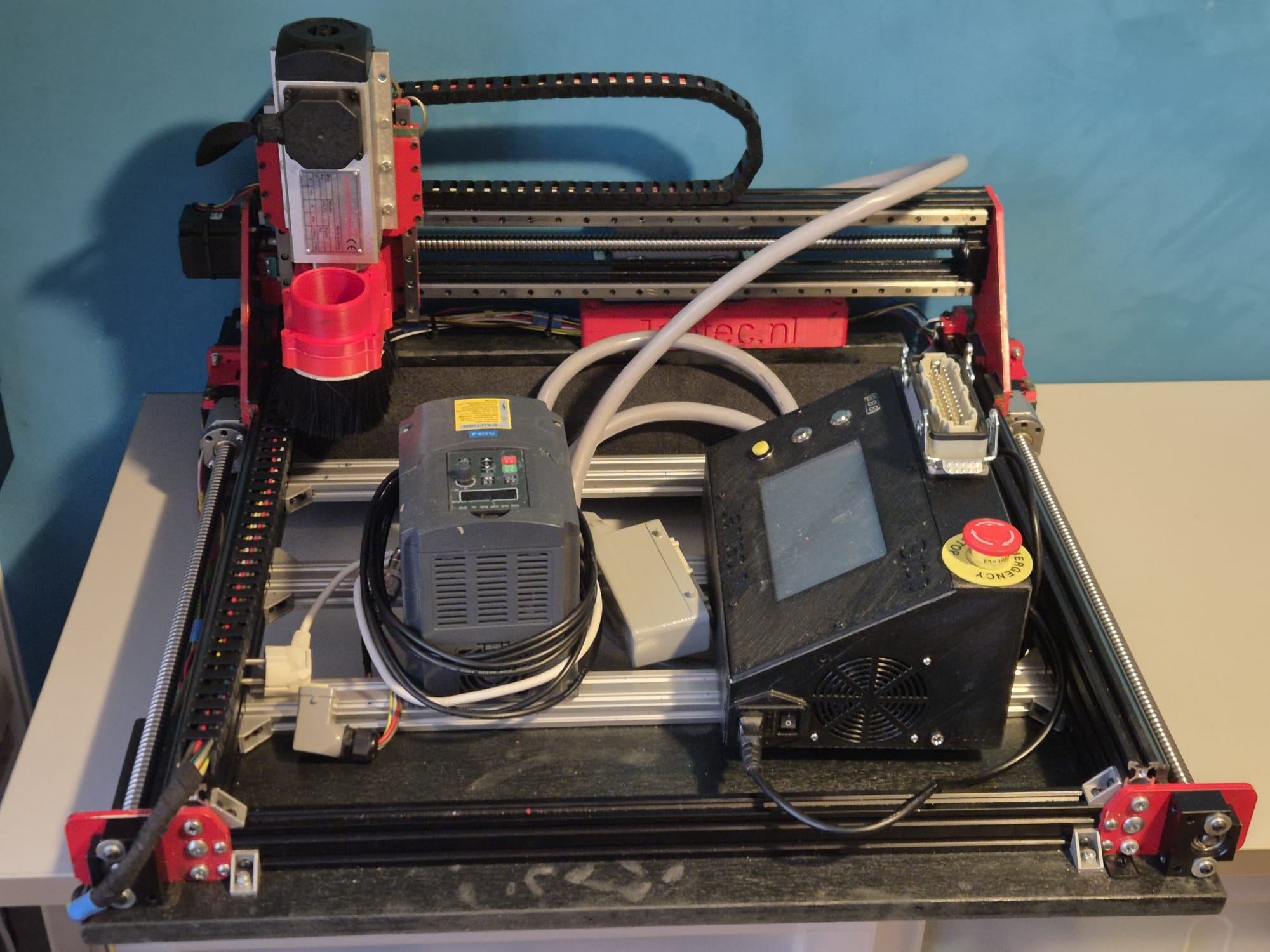
My Traction Avant conversion to 4 gears

Conversion of a 1955 Traction Avant 11BN from 3- to 4 gears

-By marrying a 1964 Citroën ID gearbox with a Traction differential-

The picture shows what happened with my original 4-gear built when I stepped a bit too much on the gaspedal. One of the drive axles broke and I had to be pushed by the youths I was driving to their ‘end of school’ party.
Here you can read how I discovered by trial and error what I think is the best way to provide my Traction Avant 11BN with 4 gears .
The Citroën Traction Avant has standard 3 gears of which the first gear is not synchronized.
In my experience, this gearbox is the biggest stumbling block for this car to come along smoothly in modern traffic.
Therefore, from 2007 to 2016 I worked intermittently on adapting an old Citroën ID/DS19 4-speed gearbox so that it works in my Traction Avant 11 BN.
As basis for this project, I used an ID donor gearbox from a 1964 Citroën ID19.
The ID 4-speed gearbox has full synchronization on the 4 forward gears but won’t fit my Traction Avant in width easily. .
The tear-down, modifications to the ID gearbox and the installation in my Traction Avant are all described in this article, including pictures.

Above you can see the rough end result with which I have now (2022) already been able to travel a few thousand kilometers.

In the end it has been a valuable project.

Driving the TA is perfect, shifting up and down is smooth and the car behaves very well.

An important advantage of the new gearbox is that the engine makes far fewer revolutions when driving at cruising speed.

Above you see the overview of the donor long-stroke ID19 engine with the 4-speed gearbox.

At the time of purchase everything was still attached: brakes, suspension, shift sleeve, HD regulator, fuel pump, alternator and so on!

The water pump had already been removed by someone else.

The donor car had serious side damage and was declared total loss.

It was a pity but I was lucky with it.

The approach

The long flanges of the 4-speed gearbox have to be turned off on the lathe. From the ends of the flanges (gearbox side), bushings are turned which will sit in the turned off flanges.

This is necessary because the bearings and seals are not available in outside sizes that will fit into the inside of the shortened flanges without fail.

New bearings and new oil seals will be enclosed in the bushings in the turned-down flanges.

The shaft chucks will be turned down by about 1mm to a commercially available inner size for a bearing and seal. (35mm axle thickness)

The flanges are turned out by 3mm to allow the axle jaws to mount properly on the TA internal body shafts.

A stainless steel bushing is turned to allow the outgoing internal TA shaft to rotate tightly in the ID crown gear.

In other conversions, this bushing is usually not installed, but the lateral pressure on the end of this shaft without a fitting bushing becomes, in my opinion, too great to be able to drive it very long without wear.

The bushing has an oil groove on the rotating inner side.

This bushing is needed on 1 side of the donor ID crown wheel and is tightly crimped into the crown wheel.

The ID shaft rotates tightly in the ID crown wheel and is slightly thicker than the TA shaft.
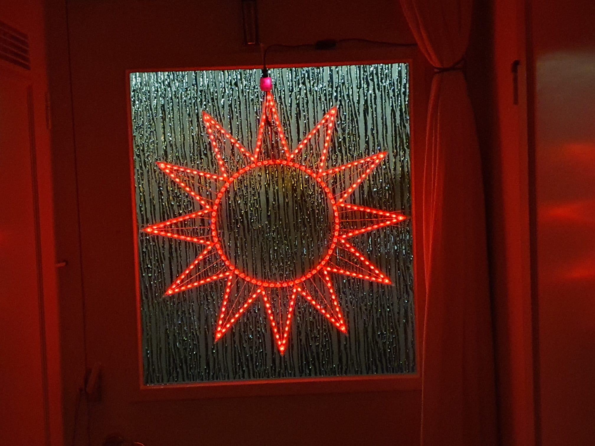
The difference in thickness is corrected by the stainless steel fitting bushing.

The satellite wheels, internal bucket axles and differential housing of the TA are reused.

The satellite wheel (which of course fits the pignon gear of the ID box) comes from the donor ID box. Of course, after the conversion you have to determine the preload on the Timken bearings again and make new spacer rings to fit the whole with the correct preload in the ‘clock’ properly.

Measure the play of the crown wheel according to the workshop manual, and so on.

This solution is robust and will not break or wear excessively.

Controlling the gears was also an important issue for me, because the Traction Avant has a different standard gear change sequence and the known ‘conversions’ to 4-speed all have an extra button or lever to operate the reverse of the gearbox. I chose to convert everything so that a regular H-fork 4-speed + reverse operation is created: · via the TA’s original shift rods – by converting the selector/levier in the cab – by doing a conversion on the gearbox with new shift rods ‘outside out’ from the control levers at the bottom of the shift tower to the original 4-banger controls.

Axles removed and further work on turning the flanges

Above is shown how I am turning the bushings for the flanges, here the new bearing and the new oil seal can be mounted.

Here the center has been removed from an old ID-19 clutch plate to serve as an extension of another fitting plate.

For convenience I have used a new TA plate for this purpose, an ID plate can in principle also be used but then the keyways must be in perfect alignment so that the plate can continue to slide freely over the primary shaft.

This action is necessary because the primary shaft of the 4-banger is shorter than the shaft of the 3-banger and the keyway of the shaft is just not far enough into the keyway of a standard clutch plate to be able to transfer the force to the plate without damage.

On the picture above you may not be able to see it very well, but the bushings are locked to the flanges with stainless steel screws/rivets so they can’t move or rotate.

Then the flange is turned off at the outside to make room for the convex protruding parts of the 10mm threaded ends of the axle clamps. this also all just fits.

Above you can see that the flange was not yet turned out….

To make the bearing caps fit, they were very carefully turned out to the size of the Timken bearings in counter arrangement in the lathe.

Above you see a turned-off flange with bushing, oil seal and bearing, mounted between gearbox and clutch housing

Next job: Extending the drive shaft to the pulley of the ID motor. 

The lengthening of this shaft was necessary because I installed a long stroke ID engine at the same time as assembling the 4-speed gearbox. 

The drive of this driveshaft on the crankshaft is slightly thicker than on the Traction engine larger and is slightly deeper recessed in the ID engine .

See photo below where the already prepared TA shaft is on top and the ID shaft is lower.

Above: Extended custom pulley shaft ready for assembly

Above you can see the center of the ID clutch pin with ID keyway from a scrapped clutch plate mounted on a new TA clutch plate. 

The welding was done with the specially made fitting bushing from ID to TA size tightly pressed into both keyways, this bushing is only removed after letting it cool down completely slowly. 

To ensure good adhesion, the welding was first done in CO2 and later grinded out in 3 places, the fitting bushing reinserted and welded again using MIG.

After that I had the welding work checked for swings of the new keyway in relation to the clutch plate.

Fortunately that was well within the norm.

Above the required fitting/shim plate of 4mm thick aluminum is shown as used to make the 100% fit of the TA clutch housing to the ID box.

The main advantage of this solution is that the satellite housing is also free from the inside of the clutch housing and you don’t have to worry about the differential running into the clutch housing.

The reason for this required adjustment is due to the fact that the position (in the longitudinal direction) of the drive shafts on the TA compared to the ID has just shifted by 4mm.

The semi-circular recesses where the flanges on the ID box fit in and where the original oil seals on the TA box fit in are not the same on the ID side versus the side of the clutch housing.

On the TA the shape is exactly the same on both sides.

On the ID box, the hole for the flange is 4mm shallower on the gearbox side and 4mm deeper on the ID clutch housing side.

With a fitting plate between the ID box and the TA clutch housing the non-round shape due to the lack of 4mm is compensated so that the purely round shaped flanges fit exactly in the (again) round hole.

I had to completely modify the scoops of the gear controls at the bottom of the shift tower so that the newly developed rods can be operated for the ID box.

It took some thinking and trying but this solution works great!

As you can see in the picture, the ID pulley only just fits next to the right-hand scoop.

By using this pulley I immediately switched to a narrower V-belt. 

That meant changing the water pump pulley, and mounting a 12 Volt alternator.

Above is the 4 mm gasket plate in detail.

During the assembly process I used thin paper gasket on both sides of the gasket plate.

That turned out to be the only way to get everything leak free.

The switch rods between switch tower (left) and transmission levers (right) to the selector in detail:

Small additional challenge with me was that due to the installation of the ID engine and- associated cylinder head- the carburetor suddenly ran in the path of these switch rods. 

Using a water pipe bender, I was able to keep the shift rods exactly clear of any fixed engine parts and it all just fit.

The gearbox without control rods mounted on the clutch housing. 

If you look closely, you can see that here I still worked with the ID insert shafts, which I had shortened. 

In the end, this solution did not work because the welded shafts kept breaking off at the weld. 

In itself, this solution is possible, but then you would have to make (or have made) new shafts].

Above you can see the extension of the primary shaft by means of a bushing that comes on the primary shaft.

This bushing comes between the primary shaft and the top bearing of the crankshaft. 

The goal is to keep the primary shaft from swinging. 

The bushing in the photo was my prototype.

There are top bearings with different inner diameters in which the primary shaft fits and so here too practice was (again) my teacher.

Clutch plate in the (equally mounted) attachment ring of the newly installed diaphragm pressure group

And the entire pressure plate with clutch plate mounted and the keyway of the clutch plate protruding outwards

Clutch housing with M10 bolts for securing the flanges.

The M10 bolts are mounted through and through in the cheeks of the housing. 

Previously I experimented with other solutions but with tapping, mounting bushings and the like I did not get it sufficiently oil-tight. 

In the above manner with rings and gaskets it is perfectly tight!

This was a bit of a job: Making 1 new one from the donor parts of 2 differentials.

In itself not difficult when you think of what will fit: 

Pinion from ID is used, so the satellite gear from ID must be used.

The outgoing shafts from the TA are used so the satellite gears from the TA must be fitted.

The thinner output TA shaft is placed in the satellite gear of the ID so a fit bushing must be pressed into the ID satellite wheel so the TA shaft can rotate freely but tightly in it. 

The Satellite housing of the TA is used (bowl-side where the gears are) with the fixed (TA) shaft attached. 

In the picture above you see the bottom left satellite gear with freely rotating output shaft.

Bottom right you see the bowl part of the satellite housing with the satellite gears and fixed output shaft. 

The original TA differential works with bucket-shafts with keyways on the outside on which the TA bucket-shafts can be mounted externally.

The advantage here is that this allows you to easily replace the large retaining rings of the TA box. 

So in the photo above, the bottom differential is the TA differential.

Above: Finished and assembled differential.  You can see the fitting bushing sitting nicely

Above you can see the made fit bushing with oil groove on the free turning inside.

Timken bearings tighten but not too tight….

Converted switch selector/levier, in the experimental phase.

Turn shaft chuck to commercially available bearing size

And the turned down result of the axle claw of the TA with inner splines.

Mounting Bracket. 

I chose a very robust setup, since the motor/box/drive shafts are all suspended from this point.

In addition, I chose to simply reassemble the cross pieces of the drive traverse to maintain sufficient strength.

Please note above: On the underside of the flanges, I have ground away about 2 cm of material on both sides.

This is because these points protrude from the original TA body.

This means that they come up against the cradle just above the passage of the drive shafts.

So I had to remove some material. I can’t remember the number of times I have assembled and disassembled the gearbox, but at least it was so many times that I can now do it blindly and very quickly.

Above again the removed material: Handy to do BEFORE mounting!

Bearing for the axle claws. I heated this part in the oven at 60 degrees before final assembly.

Ready.

Shifting axles.  Left the up/down movement of the shifter and right the left/right movement….

I had to loosen a stub axle on 1 side, otherwise I couldn’t get the axles mounted on the flanges.

Picture was taken during assembly: nut still tightening and all.

At the bottom right you can see the sensor of the cruise control hanging away.

The magnet is placed under the nut, which is still loose, with a bracket so that the sensor can see it at every turn.

Above the modified spoons from the bottom of the switch tower.

And the final result!

New driveshafts Traction Avant 11BN

First, the original shafts were overhauled, but when the 4-speed gearbox got installed, double homokinetic drive shafts were installed at the same time!

Above: At the time of purchase, Below: At the MOT inspection

Above: After replacing the old driveshafts with the driveshafts fitted with dual homokinetic joints

Assembly of the new axles whereby really everything has to be loosened….

Above the old axle

Rebuild the Traction Avant from 6V to 12Volts electric system

Sometime around 2006/2007 I initially fitted the Traction Avant with a CTA 6 volt alternator.

Above you see the CTA kit that I originally used to convert the 6 Volt system from DC to AC. You can also see the alternator from CTA installed at the time, the bracket from CTA never really worked well and seemed to be on the weak side.

Shortly after that I converted the car to 12 Volts.

I then replaced the regulator from the 6Volt type to a 12 Volt separate regulator.

That never really worked well. The charging current seemed reasonable but the voltage never rose above 12.4 Volts.

While a full battery when charged is at about 13.4 Volts.

After a lot of research and searching, I put a fixed regulator on the alternator, but that didn’t help either.

Now it seems that the field winding just can’t handle more because this alternator is wound for 6 Volts.

Seems strange to me, if you turn faster you get more voltage according to the Faraday book, but there also seems to be a saturation of the ironwork.

Later again, I converted the Traction to a 4-speed, with an ID19P engine and corresponding drive pulley for the water pump and alternator.

So in the end I just bought a new 12 (14) Volt alternator from ISKRA, actually a Mahle one.

This alternator delivers 14 Volt max and 33 Ampere max.

It still needed some modifications, of course a new bracket…

And the pulley had to be moved a little on the shaft.

I moved the big ring on the outside to the inside, behind the pulley and with that the offset was sufficient.

I found the bracket of the CTA set-up too weak, I had already replaced it for a sturdier home-made type.

The ISKRA alternator fits exactly in this bracket and further connection is no problem at all.

I have already converted my pulleys to thin belt dimensions of 10 mm because I was stuck to the pulley of the ID19P, which I wanted to keep because it is a bit larger than that of the original Traction Avant. This makes the water pump run just 5% faster and that seemed a good idea in connection with possible extra heat development from the ID19P engine, it was of course also the original pulley from that type of engine and it all just fitted with the engine mounting in the Traction Avant…

It remains to be seen, because the water pump of the TA is slightly different than that of the iD19P. It all works fine though.

The new alternator also works perfectly and charges the battery at 13.4 Volts.

In the end I did some calculations on the RPM’s you need to get a good charge.

From the graphs of this ISKRA alternator you can see that it only does something above 1200 RPM up to 7500 RPM.

The ID engine makes 650 RMM at idle up to max 3800 RPM.

The camshaft turns half the speed of the crankshaft so 325-1900 RPM.

The camshaft pulley of the ID19P is 21cm in diameter and that of the Dynamo is 7cm in diameter, this gives an acceleration of exactly 3x.

The shaft rotation speed of the dynamo is therefore between 975 and 4700 RPM. That’s too little to charge anything at idle.

The pulley of an old DS20 alternator was turned from double pulley to single pulley by me earlier and was mounted on the CTA 6V alternator, see the photo higher in this article. This one has a diameter of 6cm.  The acceleration from crankshaft pulley to dynamo is then 21/6=3.5x.

With this smaller dynamo pulley, the shaft rotation speed of the dynamo becomes 3.5 x(325-1900) RPM, so 1150-5650 RPM.  That’s just enough to charge something at idle.

See below an action picture of the moving fan and pulley c.q. belt….

Switched DC-DC proportional inverters have been made and installed for all motors such as windshield wiper and heater.  The bulbs have all been replaced for 12 Volt types and the signal driver has also been replaced.  The fuel gauge ballast resistor has been modified, the air horn pump, and the starter motor have all been replaced for a 12 Volt type.  Control lights, dash lights and so on have all been replaced as well. And… just a bit more about how it was with the DC alternator:

Ricoh Company Ltd.

Traction Avant fully electronic ignition

Really crappy, I don’t have another word for it: The old contact point ignition with its coil. I tried 3 of them on 6 volts and the combination of 6 volt battery, starter motor and points always gave me trouble, both with cold and hot starts. So I installed an electronic one, and NO 123 ignition. Just an English ignition, specially for 6 Volts OR 12 Volts. First installed with the 6 Volt installation and it worked perfectly. Still does, but now on 12 Volts.

First MOT of my 1955 Citroën Traction Avant 11BN (translation = still some work in progress)

After 13 years of standing still the first MOT in 2006, right after I bought the car, was quite a challenge.  Besides a stuck engine, broken gearbox, defective exhaust, brakes, steering knuckle covers and the like, there was also a lot of work to be done on the electrics.
TA 2006-2012 picture overview

June 2006: In any case, there was quite a bit of visible sheet metal damage and…, the engine was stuck. The brakes didn’t work, nor did the handbrake. The front bumper was in the cab. The chrome present on this car seemed to be completely depleted, including the associated rust marks. In the trunk that was barely open there should still be some spare parts. Included were new front bumper supports, as the front bumper had completely rotted off at the bumper supports. The good news: The bottom and the attachment to the engine suspension front coque was fine, the doors were good and above all: the body was hard all around. Nice detail was that the tubes on all visible parts had the familiar small plastic caps, which indicates that this car once had a full anti-corrosion treatment, including injected tube chassis. Hence the cool bodywork in the places where a TA often seems to be bad. The underside of the chassis is also completely covered in a thick layer of gunk, possibly ML, Dinitrol or tectyl. This layer is peeling off in several places. In any case, it did not prevent the fenders from rusting through. At the places where the water splashes against the fenders when driving, they are well rotted through. Anyway, the sale was closed and on July 1 I went to the previous owner with a car ambulance and my purchase price. The car has a Dutch registration and was built in 1955 but imported into NL later. And… There you go, out for the first time with my own Traction Avant. It was very hot and there were quite a few oldies on the road on Sunday morning. I could already see myself driving one of them. But that will take some time, because I experienced the harsh reality after I got the car into the garage which required quite a bit of help in the form of pulling and pushing. The first striking feature of this car is its respectable length which leaves little room for tinkering at the front and rear. The garage is 5.3 meters long and 3.3. meters wide. The width is possible, but in the length I have moved the stuff in the back of the garage to another place. The motto for now is to keep as much junk as possible out of the garage.
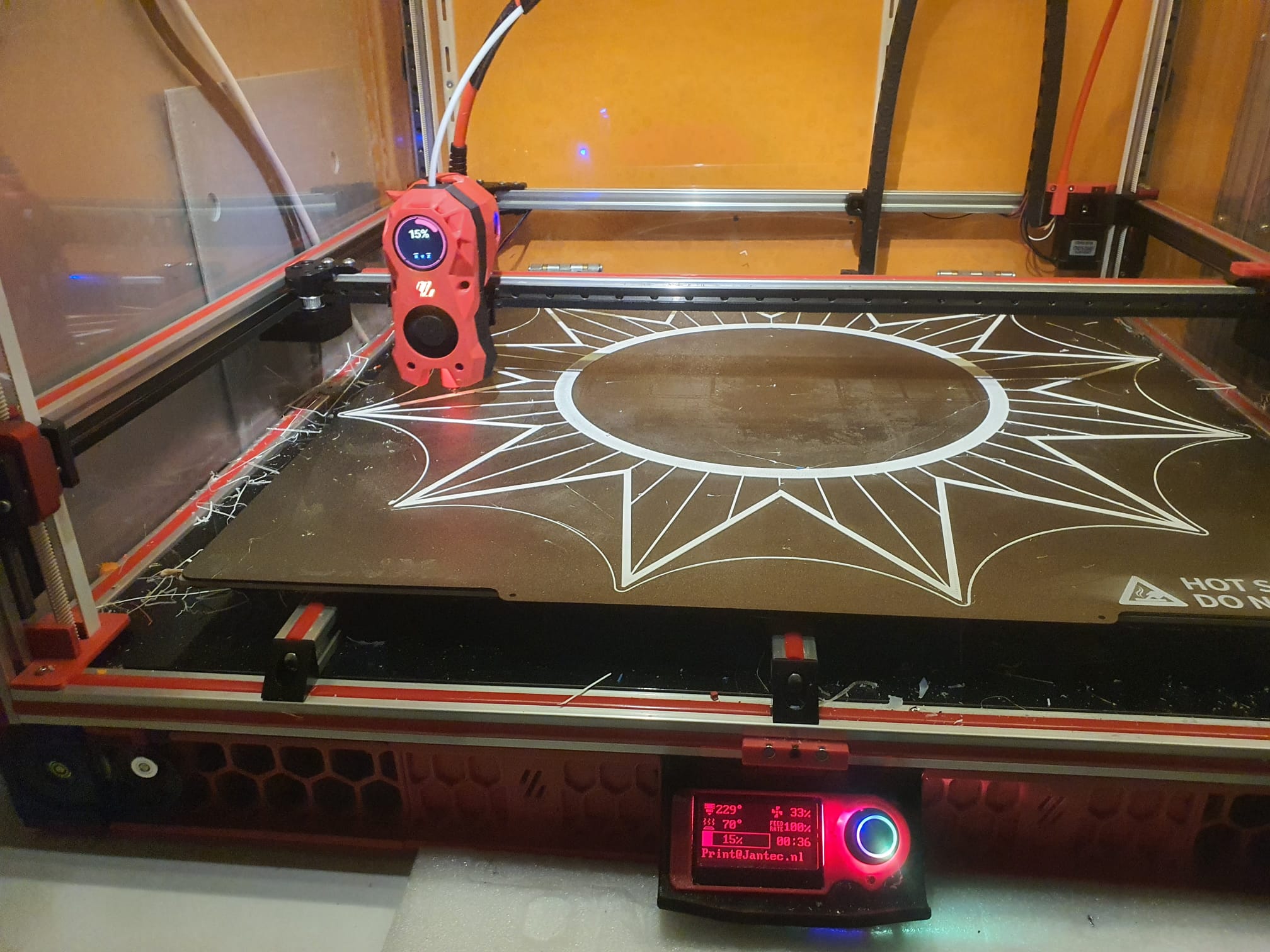
And… here we go: The first inspection! First I sprayed some release spray in the spark plug holes already removed from the spark plugs, let it soak in for a few minutes and crank… hang on. No movement at all. Repeated the action and then every day for a week, sprayed and hung on the crank, also rocking back and forth in 3rd gear. Nothing at all. Asked advice from experts. Advice is: Leave it for a few weeks with a lot of rust remover in the holes and occasionally move it around a bit in its gear. I wonder if this will be of any help after my vacation, where I am now writing this. Then let’s highlight the other issues. All moving body parts were treated with rust remover because everything was more or less stuck. At least that worked. Found some interesting things in the trunk so I now own the following extra: Front bulkhead heater (connects to cooling circuit) with covers and air hoses; Unicode 3 complete carburetors with membranes and nozzles intact etcetera; Fully complete used workshop manual; Olyslager booklet for the 11 and 15 ; Complete gasket set including new head gasket A large number of bolts and nuts Hoses for everything Clignoteur / lamp holders and defective caps Bulbs Relay The missing wooden window crank knob from the left rear Blankets Sleeping bag Floor covering and so on After careful selection, my wheelie bin was packed and I was left with 2 boxes of parts that might be useful in the future. Inside the cabin, I discovered that the original upholstery that is under the red ribcoard covers still looks pretty good. It’s a different story with the lining of the doors where the holes for the control handles are located. So reupholstery.

Ricoh Company Ltd.

I had already noticed that the window of the right front door is only attached to the control in the door with 1 attachment point. So I had to repair that as well. The ventilation flap didn’t want to open anymore either. After careful examination I discovered that it was simply covered with lacquer. After some more careful feeling and probing I started to remove all the steel putty. Apparently this car was once taken in hand by a putty expert and then largely painted. At least this goes for the rear under the windows including the screens and the trunk on the outside.

Ricoh Company Ltd.

After removing the putty I was left with a body that didn’t actually have that many holes in it, and certainly no holes in the wrong places. The holes that were there, can be welded on with new sheet metal. So that is going to happen. The rear mudguards will have to be finished, because the piping between the coque and the screen has been filled and painted.

The left front fender was a setback because it had a lot of putty on it that was cracked at the bottom of the tip. After removing the decorative point and removing all the putty, a nice aluminium support under the point became visible where the putty was hanging on. Long live the do-it-yourself job! That’s going to come off as well. Order a new point, weld it on and you’re done. The shape of the entire front mudguard will be restored. Now you can push on it and the middle part just moves a good centimeter vertically up and down.

There are no holes in the trunk, but I did remove a lot of rust but all in all I just took out a quarter of a filler with my dustpan and brush.

Ricoh Company Ltd.

Removed all the mess inside and dented out the first dents with the bolka hammer and counter punch. Then at least the model is back in neatly.

Then we have to look for a good rust converter because I have no illusions about turning it into a new car. Preservation now seems the best option for both the lower and upper parts.  On the internet I saw a good preservative that you can use to treat the whole underbody by first cleaning it, de-rusting as much as possible and then applying this preservative. This will connect with the corrosion on the steel and then close it off completely. My dream was to strip the car and shovel the coque but I’ll let that go for now. First let’s see if an MOT is possible in the long run.

First I continued with the visible part of the exterior: I removed all the rust spots with a putty knife and brushed them with the steel brush on the drill. Then I smeared some good old fashioned Noverox on it to make sure it won’t rust for a while. On such a gray car you know immediately where you have to do some touching up because the Noverox forms a black area where it finds corrosion. So the grill, hood, part between the engine and the front wings, the front wings, doors, doorposts, gutters, rear window, trunk, rear fenders and so on were all treated and actually it was not too bad.

In the meantime, I tried to start the car with a battery to get the engine loose, but you get the idea: No result at all. I wonder if the car was put away with the engine running. Just taking a good look at the oil in the crankcase. I don’t know if you can draw any conclusions after 13 to 20 years but the oil was up to standard and looked dark and used. Not like my old Renault after a head gasket leak: completely white. Anyway, if the engine doesn’t come loose, it will have to be removed anyway. Removing the head without further dismantling makes no sense.

On to further inspection. Apparently the previous tinkerer had already refurbished the front train because it is completely covered in orange lead primer, the kind that is so handy but that you can no longer buy because of the environmental aspects.

The carburettor was removed and the right 2 studs of the inlet c.q. exhaust manifold were turned completely inaccurately just inside the head. That is a nice job for the drill and the turning kit.

Turned-off studs in cylinder head

Put it in the de-ester already. Might as well remove the manifolds and put in all new studs. OK, that is how you get your chores but good. If the engine has to be removed the manifolds have to come off anyway.  Maybe replace the valve seats for harder ones because of the unleaded petrol.

Then on to the inspection tour: All the original things you wouldn’t expect from a tinker car are still there, such as an original 2 liter oil can including bracket and spring on the inside of the left hood.

Then let’s just fill and charge the 6 Volt battery. Sure enough, there is still a tiny bit of life in it. Enough for the horns and lights. But the clignoteur doesn’t work or is just not there.

Still need to check the chassis and coil number to see what the actual year and month of manufacture is. Can I see what type of engine and so on is actually in it.

Ricoh Company Ltd.

A nice detail is that the radiator is renewed, at least the inner part and that the original operation of the roller shutter for the radiator still works flawlessly. After the necessary de-rustering and careful adjustment of the shutter, it worked perfectly as it was originally intended.

Ricoh Company Ltd.

Went to the parts store and they still had original brake fluid for TA and ID/DS early years. It was a very old bottle but I bought it anyway. Price was still in guilders with old VAT rate but with what’s to come I can use an old price!

As long as the engine is still soaking with the de-ester I will continue my expedition to restore everything I find as original as possible. Go ahead and start on the brakes first.

Ricoh Company Ltd.

Another inspection trip under the car and it just looks really tight. I removed layers of black gunk in all the right places with my awl and putty knife, but steel came out cleanly everywhere. It looks as if a whole new bottom plate was put in at one time or that the car has been maintained very well in this aspect. In any case, it is a boost that I needed for I am not making much progress with only negative reports.

Ricoh Company Ltd.

By the way, I still have to order new license plates, at least one because in the front there is one where the plastic letters have mostly disappeared. And oh yes, my registration certificate part 1 is almost torn and part of the paper has perished. I don’t know what text I’m missing but the serial number and such is still on it. I will send an application to the RDW asap for replacement of part 1. Fortunately you don’t really need it for the registration, at least not at that second office of post offices where I was.

Original license paper (from 1970, import date into NL) part 1

In any case, I will cover the door panels because it really doesn’t look like it with those holes in it.

Then I can also take care of the window mechanisms. I still have to figure out how to remove the door handle and window crank but I have one of those handy workshop manuals that doesn’t say just that. Then I’ll just have to see what the trick is: A hidden spring or just pulling hard….

30-7-2006

Sunday, time for reflections….

Removed the rocker shaft last week, you never know….

The engine is still stuck.

I did replace the rear brakes from steel to copper, at least where it was bad. In the end it only turned out to be the pipe from the left rear wheel to the right rear wheel. It is attached to the rear axle with 3 clamps. Of course it started leaking under the middle clamp, in the middle of the rear axle.

Overall condition of the rear floor is okay, except for the left sling of the petrol tank, which is secured with rope. So also put it on the wish list.

Ricoh Company Ltd.

The new setup to get the engine loose is now as follows:

Take out the crankcase while the engine is still in it. That means a lot of bucking under the front of the car, draining and especially overalls and gloves.

If the pan can be removed, it is important to loosen the connecting rods one by one (first remove the oil pump?) and to make the pistons movable. If that is successful and the bearing shells c.q. inside connecting rod and crankshaft are OK, then reassemble and make the rest rotatable.

I have the time so it should be possible, provided the sump pan can indeed be taken out while the engine is still in the car.

Am reluctant to take the head off. On inspection, the water level was still above the cylinder head, so I assume that the head gasket is not leaking and I should therefore stay away from the head.

If it is not possible to get the pistons loose with the engine in the car, there is still the option to remove the head and the pistons including the connecting rods and wet bushings. First make a good mark of course but the condition remains that the carterpan has to come off with the engine still mounted in the car.

Meanwhile, removed the upholstery from the front doors. The front right door had a lot of rust in it AND the window mechanism is broken. Needs a new rail in at the bottom of the window. The rest is still OK. Wondering if such a rail can be bought separately. It looks like a clamping rail around the steel edge at the bottom of the window. So also on the wish list.

Last week I also mounted the bumper brackets and the bumper. Wrench cap 41 and hang on to those coquem nuts. Took two hours to get both completely loose. Good stuff that rust remover. In the meantime I removed all the gunk from the triangles and other parts that go to the front wheels. In the process I found about 12 lubrication points which I immediately lubricated. I was surprised that I didn’t need to put a lot in to see the gunk coming out already. That is a good sign because there was still compound in the steering knuckles and bushes.
Did other things for a week. Thought about how to proceed.
Removed the crankcase.

Carterpan eraf

Goed gekeken aan de onderkant in de cilinderbussen. Bij de voorste 3 cilinders was de losmaakvloeistof langs de zuigers gelopen, de achterste was helemaal droog.

Onder-binnenzijde 3e cilincer die lekker olie-achtig was

De onder- binnenzijde 4e cilinder zat nu nog muurvast

Drijfstang van achterste zuiger losgemaakt, met de bouten nog in de drijfstang. De krukas beweegt als er druk op wordt uitgeoefend. De eerste 3 zuigers zitten dus los.

Drijfstang achterste zuiger weer vastgemaakt.

Water eruit laten lopen via aftapplug in zijkant blok.

Tuimelaaras was al verwijderd,  de kop eraf gehaald inclusief waterpomp.

Gedemonteerde cilinderkop incl. waterpomp

Cilinders en zuigers NA de losmaakoperatie, vlak voor het monteren van de nieuwe cilinderkop

En jawel, de oorzaak van alle ellende: Lekke koppakking in het uiterste rechterhoekje (vanaf de bestuurder gezien) bij de achterste (4e) cilinder.

Dus roest in deze cilinder maar gelukkig staat de zuiger bijna onderin.

Schoonmaken maar en schade bekijken.

Cilinderwand iets geroest maar geen putjes of inroesting. Met 400 waterproof schuurpapier heeeel zachtjes de roest verwijderd. Weer alles schoongemaakt.

Natte bussen geborgd met ringen en bouten zodat ze niet per ongeluk loskomen als de zuigers bewegen.

Onderkant van de cilinders ingespoten met roestoplosser.

Met een blokje zacht rondhout en een koperen vuistje heeel voorzichtig de 4e zuiger naar beneden getikt.  Olie op de zuigers gedaan.

Vanaf onderzijde vervolgens de zuiger met een blokje zacht hout heeeel zachtjes met koperen vuistje de 4e zuiger naar boven getikt.  Deze actie een paar keer herhaald waarbij al na de 1e keer alles merkbaar soepeler ging.

Vervolgens via de startslinger gedraaid tot alles soepel liep.

Na een goede schoonmaakbeurt van de zuiger-bovenzijdes, de cilinderkop, kleppen en het reinigen van het blok en kop waar de pakking moet komen, nieuwe koppakking met olie besmeurd en gemonteerd, kop erop en gemonteerd.

Tuimelaaras gemonteerd, stoterstangen gemonteerd, kleppen koud gesteld op 0,4 mm.

Ricoh Company Ltd.

Nieuwe carterpan-pakkingen gemonteerd. Carterpan er weer op.

Spruitstuk er weer op, dat moest er af want de vorige sleutelaar had 3 tapeinden afgebroken. Dus allemaal nieuwe tapeinden erin en weer gemonteerd. Carburateur erop, benzineleiding erop.

De waterpomp had ik aan de kop laten zitten, dus dat zat gelijk goed.

Ontsteking gesteld, bougies erin, water in het koelsysteem.

Accu gekocht, 6 Volt natuurlijk, en aangesloten.

En.. starten maar.

Maar alleen maar plofjes en helemaal geen mooi ronkend motorgeluid.

Nou ja, even nadenken maar…  Hoe zat het ook al weer, je hebt carburatie nodig, ontsteking en.. compressie! De eerste 2 werkten. Dan de compressie maar meten..  En jawel, bij cilinder 1 gelijk al een probleem met compressie van 1 bar.  Daar loopt zo’n motor natuurlijk nooit mee.  De 2e was iets beter en nummer 3 en 4 beiden 3 bar.

Dan maar even olie erop (de zuigers dus) en opnieuw meten.  Geen verbetering.

Dat betekent een probleem met de cilinderkop.  Kop eraf halen, gelukkig weet ik nu hoe dat moet.

Kop helemaal kaal gemaakt, alle uitstekende delen eraf en achterin de auto gelegd.

Waterpomp (2 weer mooi groen gespoten delen) en spruitstuk

Bij CTA een revisiekop gekocht, kan ik gelijk gewoon op loodvrije benzine rijden.

Nog in plastic verpakte revisie-cilinderkop

Kop thuis met nieuwe pakking gemonteerd (en waterpomp, spruitstuk, tuimelaaras, stoterstangen, kleppen stellen, carburateur, enz…, scheutje benzine in het carburateurgat gegoten)  en… in 1 keer starten!

Bewegende beelden!

Benzinepomp aangesloten, benzine in de tank, filter ertussen, starten en… lopen!

Carburateur bijgeregeld op stationair toerental. Loopt fantastisch stabiel langzaam rond.

Uurtje laten lopen en laten afkoelen.  Bougies verwijderd en compressie gemeten.  Elke cilinder tussen 6 en 6,5 Bar.  Daar doe ik dus even niets meer aan.

Verlichting

Alle lampen gecontroleerd en waar nodig vervangen, clignoteur gemonteerd.

Eerste proefrit

Op zondagmorgen was het zover: Lekker rustig op de weg dus maar eens proberen hoe het gaat. Inmiddels de wagen verzekerd want dat is wel zo handig als ie naar de APK gaat zometeen.

Rijden gaat wel, de koppeling hapt wel heel erg. Schakeling gaat wel goed als je maar heel langzaam doet. In z’n 1 of achteruit gaat moeilijk dus ontkoppelen gaat niet helemaal vlekkeloos.

De tweede versnelling maakt een vreemd bijgeluid.

Remmen is gewoon eng: Naast de verschillende geluiden trekt de auto geheel naar links. Zal rechts wel vastzitten.

Bij terugkomst besloten om het volgende eerst te doen: Remmen, versnellingsbak/tandwielen inspecteren, koppelingsplaten vervangen en alles goed schoon- en vetvrij maken qua koppeling.

Daarnaast de oliekeringen van het differentieel bij de diff assen vervangen.

Bij inspectie bleken de moeren van de korte assen bij het differentieel los te zitten. Oeps, gelukkig maar een korte proefrit gemaakt….

Remmen

Wielnaaftrekker gekocht want met mijn universele trekkers lukt het echt niet.

Voorste wielremcilinders afgenomen, leeggehaald en goed bekeken en bevoeld. Zijn van binnen helemaal hard. Geen putjes of iets dergelijks.  Nieuwe cups en stofkapjes gemonteerd. Leidingen zijn OK. Nieuwe voeringen gemonteerd.

Voering van linkervoorwiel grotendeels gewoon verdwenen; rest versleten tot halverwege de koperen klinknagels

Voering erg dun geworden

Proefrit gemaakt.  Halverwege steeds meer herrie wanneer de bak in 2 staat. Verder alleen in 1 en 3 gereden en snel naar huis gegaan. Remmen doen het goed. Moet achterwielen qua remmen nog doen.

Versnellingsbak

Krik onder carterpan (met veel stophout) en krik onder koppelingshuis

Alles eerst verwijderd: Motorkap, Grill, toeters en radiateurscherm, radiateur, ventilatorfan, poeli van de aandrijfas voor waterpomp e.e., subframe.

Voor de grote demontage-operatie van de bak, koppeling, aandrijving

Bij afname van het bakdeksel bleken 2 tanden van het tandwiel van de 2e versnelling dat op de primaire as zit, te zijn verdwenen. OK. Valt even tegen. De tanden vond ik onderin de bak. 1 is oude schade en 1 is proefritschade.

Tandwiel bij de TAN club 2e hands besteld.

Zo erg kan het dus zijn in een bak.

Speling op de lagers gemeten en is allemaal binnen norm.

Om primaire as te verwijderen moet kroonwiel eruit. Gehele ‘ klokje’ verwijderd.

Mooi origineel groen gespoten

Zo. 10-9-2006: Koppelingsplaten vervangen. Koppelingshuis afgenomen, gereinigd en groen gespoten.  De lastige M7 bouten naast de as van de aandrijving voor de waterpomp en dynamo vervangen door Imbus M8. De 2 gaten in koppelingshuis opgeboord naar 8 mm en schroefdraad in motorblok uitgeboord op 7 mm en getapt op M8 metrisch.

Kruiskoppelingen vernieuwd met nieuwe kruisjes en naaldlagerbussen etcetera.

Kruistukje na grondige schoonmaakbeurt, herbruikbaar als presse-papier

Gelijk stof- en vethoezen gemonteerd over de aansluiting van de difstukken op de aandrijfassen.

Druklager helemaal gereinigd en in compound gezet. Nieuw veertje dat druklager terugtrekt gemonteerd want dit was verdwenen. Drukgroep schoongemaakt met perslucht.

Koppelingsvlakken gereinigd van drukgroep en vliegwiel. Nieuwe koppelingsplaten gemonteerd.

Koppelingshuis gemonteerd.

Zo. 17-9-2006: Tandwiel 2e versnelling weer gemonteerd,

Primaire as met gemonteerd tandwiel 2e versnelling, boven de as ligt de synchronisateur en los daarin rechts het 3e versnellingstandwiel. Links net boven de as het tandwiel voor 1e c.q. achteruit.

Primaire as erin, pignonspeling gesteld op 1,3 mm tussen pignon en satelliethuis m.b.v. wegnemen van 2 shims en gelijktijdig invoegen van de pakking op voorzijde bak van secundaire as.

Pignon.

Voorzijde versnellingsbak met (boven) gemonteerde primaire as en (onder) secondaire pignonas.

Shim en lagerhuis secundaire as   , Shims en voelermaten voor meten pignonspeling

Wo. 20-9-2006: Kroonwielspeling op 0,2 mm gesteld d.m.v. stellen van de Timkenlagers van het differentieel.

Praktijk van de meting in de garage van mijn broer

En de theorie uit het originele werkplaatshandboek Differentieelstukken gemonteerd met nieuwe keerringen. Pakkingen tussen koppelingshuis en versnellingsbak aangebracht, versnellingsbak aangebracht,

Aanschuiven van de bak op het koppelingshuis.

De korte aandrijfsasjes zijn hier nog los t.o.v. het differentieel. Aansluitingen tussen diffstukken en aandrijfassen aangesloten met nieuwe borgmoeren M8. Vervolgens alles weer gemonteerd: Vliegwiel, dynamo, waterpomppoelie, schakelstangen, beschermplaatje, afdekkap versnellingsbak met nieuwe pakking, olie bijgevuld, alles met nieuwe bouten en moeren gemonteerd.

Radiateur gemonteerd, auto schoongemaakt en ontdaan van alle vet en smeer.

Alle roest verwijderd, Fertan opgebracht, afgespoeld en grijze Bodyschutz aangebracht op alle delen waar ik later niet meer bij kan komen.

Auto zo ver gemonteerd dat de motor weer loopt en alles kan worden uitgeprobeerd

De mensen van de RDW hebben e.e.a. erg netjes opgepakt en zonder bijkomende kosten tegen inlevering van de vorige versie een nieuwe gemaakt. Lekker proefgereden op een hele zonnige vrijdagmiddag 22 september 2006. Aan alles gedacht maar toch vergeten benzine mee te nemen. De tank bleek nogal te lekken en dus stond ik na zo’n 4 kilometer helemaal stil. Gelukkig een hulpvaardige broer die op de motor met 5 liter reservebenzine aankwam. Benzine erin, even doorstarten en gaan met die banaan!

Onderweg wat olie verloren omdat de klepdekselpakking die van rubber was: zo’n mooie nieuwe, ongeveer 2 centimeter langer was geworden. Maar even door broerlief professioneel dichtgekit.

De benzinetank lekte zo erg dat hij geheel leeg is gelopen.

Naar huis gereden met een slang in de reservetank. Paar liter benzine erin en dan kom je wel weer thuis.

Het positieve nieuws: Remmen, sturen, (ont)koppelen en schakelen als een zonnetje. Wegligging prima, geen rare bijgeluiden uit motor of bak enzovoorts.

Moet nog wel de carburatie checken op acceleratiepomp en sproeiers want stationair gaat prima, voluit gaat prima maar daartussenin gaat het met horten en stoten en dat is erg jammer.

Inmiddels de luchthoorn gerepareerd en dat is errug leuk onderweg. Tweetonig claxoneren op z’n ouderwets met een speciale handel aan het stuur.

Inmiddels alle instrumenten en controlelampen vervangen, dimmer van de cockpitverlichting vervangen en een heuse stuurschakelaar gemonteerd voor de clignoteur. Ook het lampje in de oorspronkelijke schakelaar vervangen.

Antenne gemonteerd voor de 6 Volt Philips autoradio die het ook errug leuk en origineel doet.

Ricoh Company Ltd.

Binnenzijde met de bijgeleverde ribcoard (rode) stoelhoezen

Ricoh Company Ltd.

En de oorspronkelijke bekleding natuurlijk, met hier en daar een slijtageplekje.

Ricoh Company Ltd.

Achter- zij aanzicht in de garage

Unicode
  • Zij-aanzicht in de garage 2-10 tot 9-10-2006:
  • Achterremvoeringen, wielremcilinders, leidingen vervangen
  • Luchthoorn gerepareerd
  • Oliedrukmeter en watertemperatuurmeter c.q. voelers gemonteerd
Ricoh Company Ltd.
  • Voor- en achterremmen flexstukken vervangen
  • Carburateur vervangen want auto hort en stoot bij stationair rijden en optrekken
  • Gaatje in vloer voorin rechts : plaatje overgepuntlast
  • Nieuwe flexibel slangetjes voor vacuümvervroeging aangebracht MET klemmetje op ontstekingsaansluiting
  • Defecte strop onder benzinetank gerepareerd en benzinetank vervangen
  • Uitlaat vervangen
Ricoh Company Ltd.
  • Trekhaak gemonteerd
  • Ventilation grille de-rusted and temporarily painted
    Steering wheel replaced by newly purchased original steering wheel
    Underside of the car was cleaned, Fertan applied, rinsed and sprayed in gray body schutz
  • Reverse light, wiring and switch fitted
  • Fog lamp, cabling and switch fitted
Ricoh Company Ltd.
  • Wash, color and reapplied: red chair covers
  • Original heater connector mounted on radiator
    Wipers replaced
    New distributor complete incl. bushing, new spark plugs, ignition cables
  • Leather dust covers steering mounted
    Rear indicator bulbs replaced and 25 watt bulbs mounted
    Citroen plate mounted
    New ignition coil
    Bodywork repainted on rusted parts
    Floor panelling in front of the seats (temporary)
    Valves set
    Ignition set

    APK on 12-10-2006

    Actions following MOT done (14-10 till 30/10/2006):

B
4
1
5
7
2
0
1
1
  • 001: Identification number 11B 415027 found on coque (is original so stamped upside down and badly readable)!
  • 111: Change indicator covers front from white to orange

BEFORE THE ACTION

AFTER THE ACTION

502: 4 pieces of greasebags on steering knuckles L+R replaced below + above
112: Front left headlight replaced by new glass and a new (56 years new in original box, cost 109 Euros) mirror, both headlights also adjusted to height
801: Rear right wheel replaced by a spare wheel and brakes loosened a bit because of some wear on the right rear side

  • 502: Bronze bushings in triangle axle looks like steel on steel but this is original bronze on iron so no action needed, there is no play on the bushings, some side play within the norm. Only much lubrication is required
  • 702: Steering ball joints L+R replaced with grease fittings (steel + rubber ring), lubricated
    702: Steering ball joints L+R adjusted because of > 1 mm play
  • End stop (adjustable part) left-hand steering replaced and adjusted
  • Exhaust with additional support attached to gearbox

Drive on Sunday 15-10-2006

Finished for now, had an MOT and after a short recovery we will continue with the structural things like electrics, sheet metal and paint, interior and so on…

Ordered 13-11-2006:

Air filter rubber carburetor 11D
Carburetor repair kit Solex 32/34 PBIC
4 pieces 11CV ball joint key
Pedal rubber brake/clutch
Mudguard trim, gloss black Ø7mm
Spraycan window strips light grey
Alternator 7,4V/35Amp + support


Voltage regulator electronic 7V

Later done (2007):

Body where needed spray painted in grey (original color)
Upholstery and felt bottom and side/under dash ordered 5-10-2006 from CTA
Buy chrome inner caps
Tankcap with lock
6 to 12 Volt converter
Better sound, radio and CD with MP3
Heater mounted (Clayton) and windshield heater connected
Fenders completely repaired and painted black
Body panels repainted in original color
Seat and door upholstery panels bought, to be installed after all rust and headlining is removed

Ready to drive – All done but still work to do on the trim and fenders. In this picture the holes in the mudguards are provisionally closed.

In this state I drove a few times 200 kilometers without any problems.

Total of 2000 kilometers driven until April 2007.

From the beginning of April 2007 I started to refurbish the exterior. See the following pictures.

Next to that some work needs to be done on the brakes because the return movement is too stiff which causes the brakes to get hot in traffic.

Also the front wheel bearings need to be adjusted because there is some wheel play.

The mounted thermostat does its job well but because warm water enters the radiator in one go the final level in the radiator is about 5 centimeters below the top edge. This turns out to be sufficient in practice. Despite the thermostat, the radiator roll cap has proven to be necessary during the winter.

PS: In the meantime 1 small hole has been drilled in the thermostat to keep the circulation always going a bit.

The welding and spraying work

April 10 to 30, 2007:

Fenders disassembled.

First we stripped everything as much as possible, applied Fertan, let it work and rinsed it off.

Around the holes made bare. Cut out the bad parts.

Welded in 1 replacement part (point left front mudguard)

For all parts to be replaced, beaten up and welded in place suitable body steel of 1.5 mm (MIG)

Grinded where necessary

Sprayed with INOX, inside and outside against rusting of the welding

Flameproofed with 2K, sanded in shape with 120 and 180

Spray putty

Fine putty, sanded flat with 600 and 800

Black 2K lacquer on top.

Fenders mounted with new piping.

After the fenders, it’s the body’s turn.

All rusted spots were cleaned, Fertan applied.

Welded where necessary and then ground smooth.

Then filler, sanding, filler, sanding, etcetera.

Spray putty on it and then the (most) original color over it.

Reassemble everything, polish it and then proudly drive around!

That all sounds simple, but it took about 3 months…

July 2007: After the paint job on the body it was enough for a while.

The trunk, hood and grill will come next time.

All rust on grill, hood and trunk is preserved and the bare spots are painted as a temporary measure.

The headlight supports have been replaced by aluminum polished supports.

After painting the trunk, hood and grill, it will be the turn of the interior replacement….Probably in winter 2007/2008.


Traction Avant repair 3-speed gearbox with 2 broken teeth on 2nd gear

After the purchase, the TA’s gearbox turned out to be defective. 2  teeth were missing from the 2nd gear.  Later I (fortunately) discovered both teeth in the gearbox’s oil sump.

This second gear is the most vulnerable gear, especially because people often try to drag a TA in 2nd gear. 

Or they try to get the engine loose by force dragging it in 2nd gear.

Fortunately I was able to buy a NOS gear via the TA club warehouse and after an evening of reading the garage manual I dismantled and reassembled it. 

Easy to do most of this myself. With help from my brother in his garage, to set the Timken bearings at the correct tension and adjust the play of the differential.

Also mounted new oil seals.


June 2006: Picking up my Traction Avant

After the sale was completed for Eur2000,= I went to pick up the Citroën Traction Avant 11BN (built 1955) in Leiden with the rented car trailer.
The 3 below pictures are the seller’s ones from Marktplaats.nl:


At home:

After the first inspection it turned out that nothing actually worked.

The engine was stuck, there was water in the oil, the gearbox was broken, holes in the fenders, headlight mirrors rotten, rear light lenses broken, gas tank leaking, exhaust rotted, tires on, front bumper was rotted off and so on.

But the bottom, side, roof and body were rock solid.

Read more: FIRST MOT