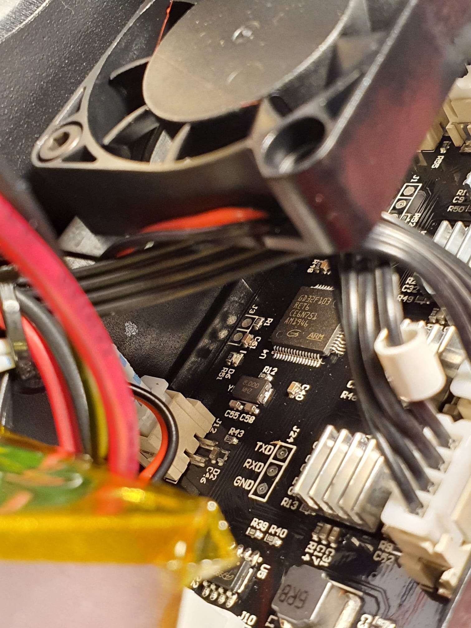
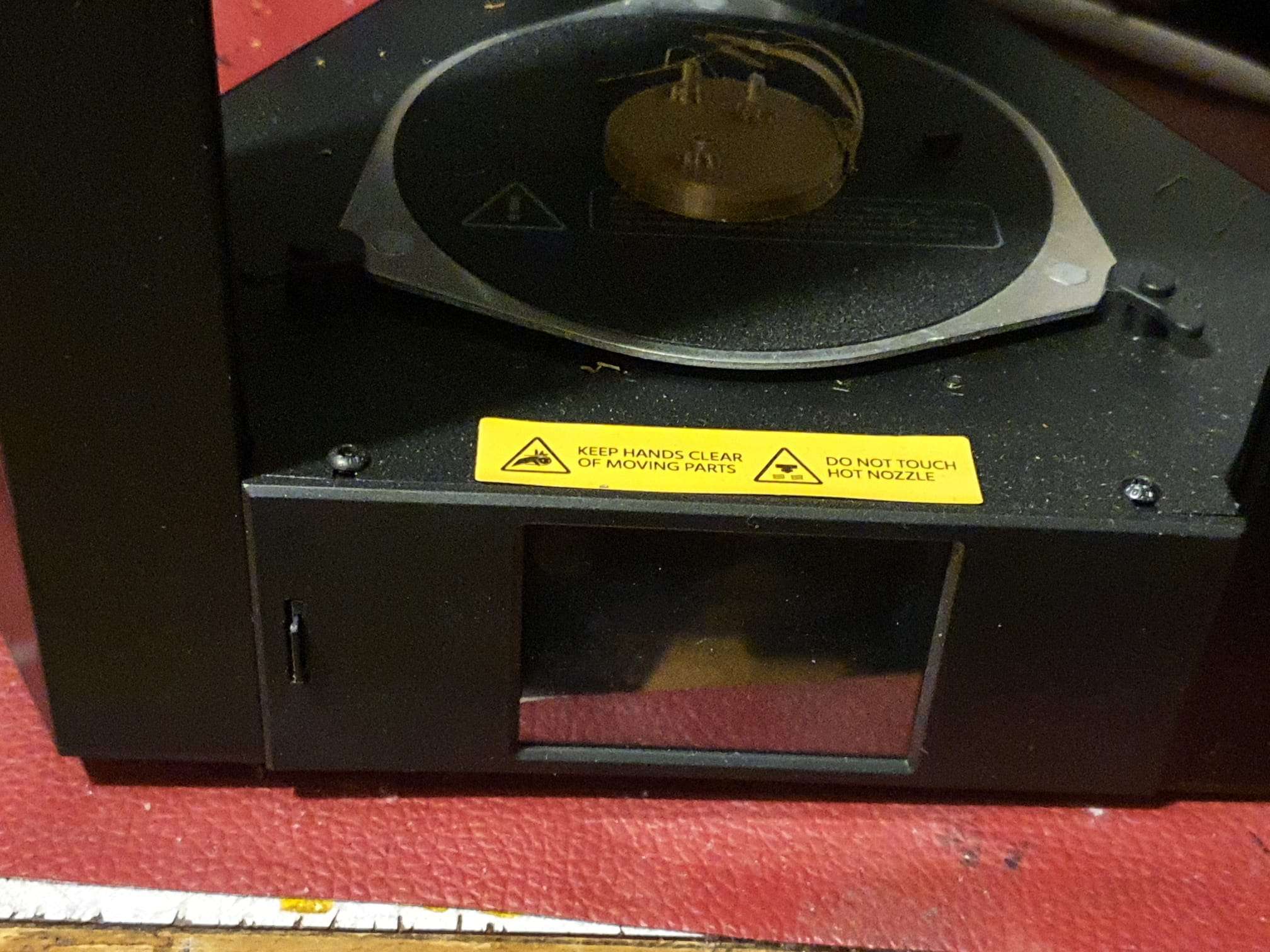
Monoprice MiniDelta V2 GD32F103 ARM MJR83B motherboard

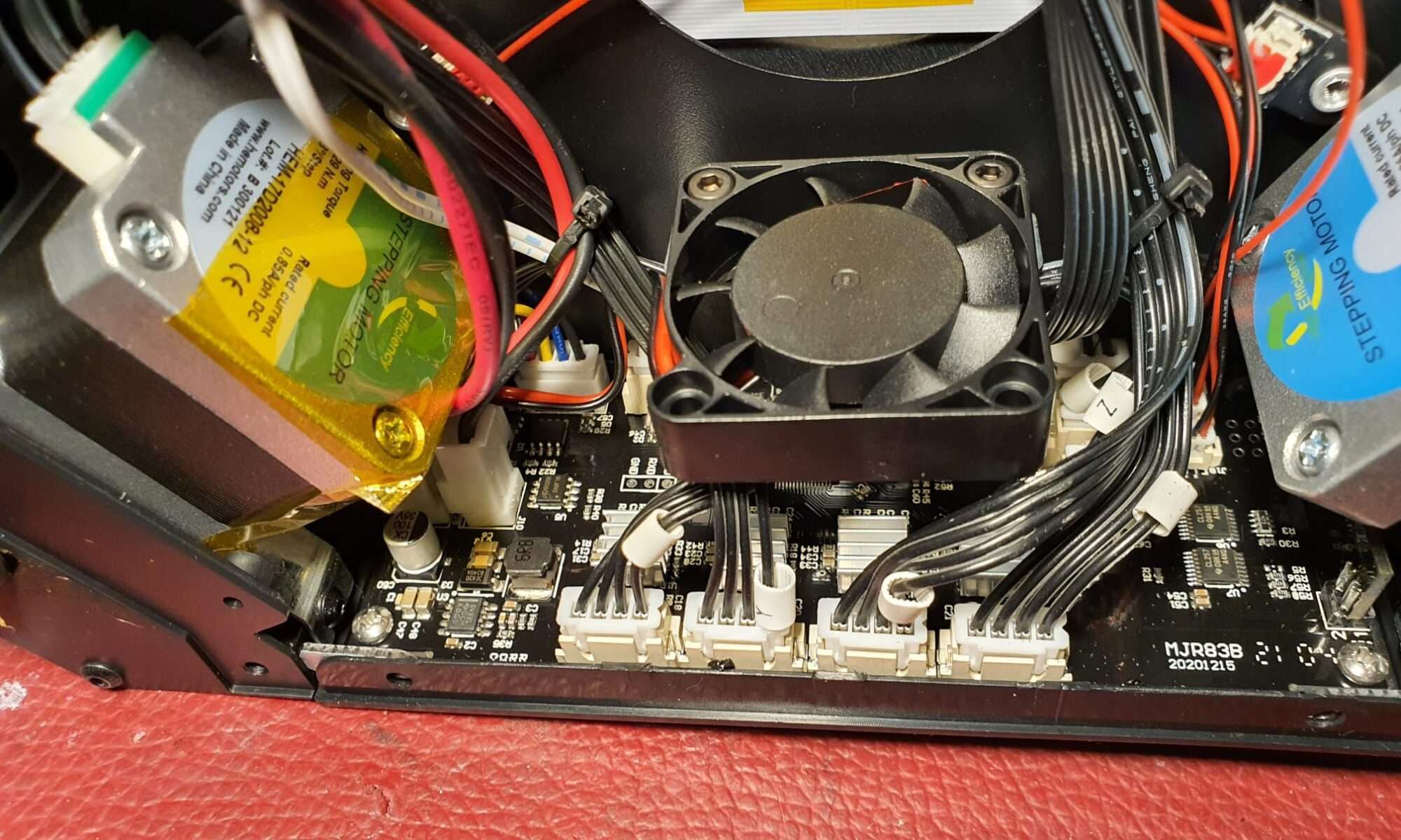
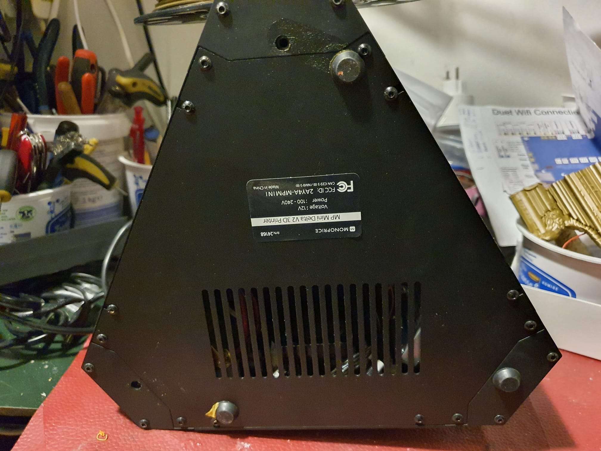
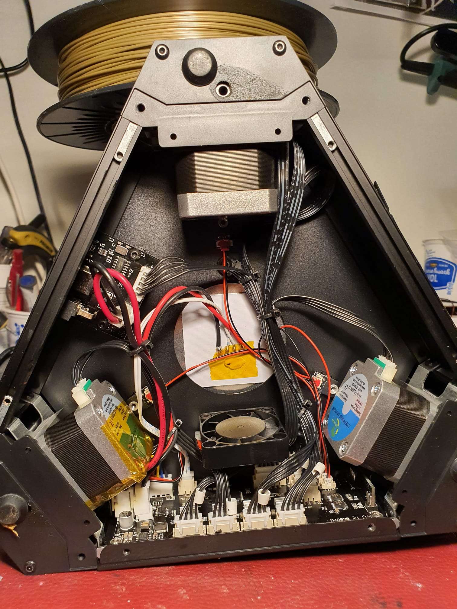
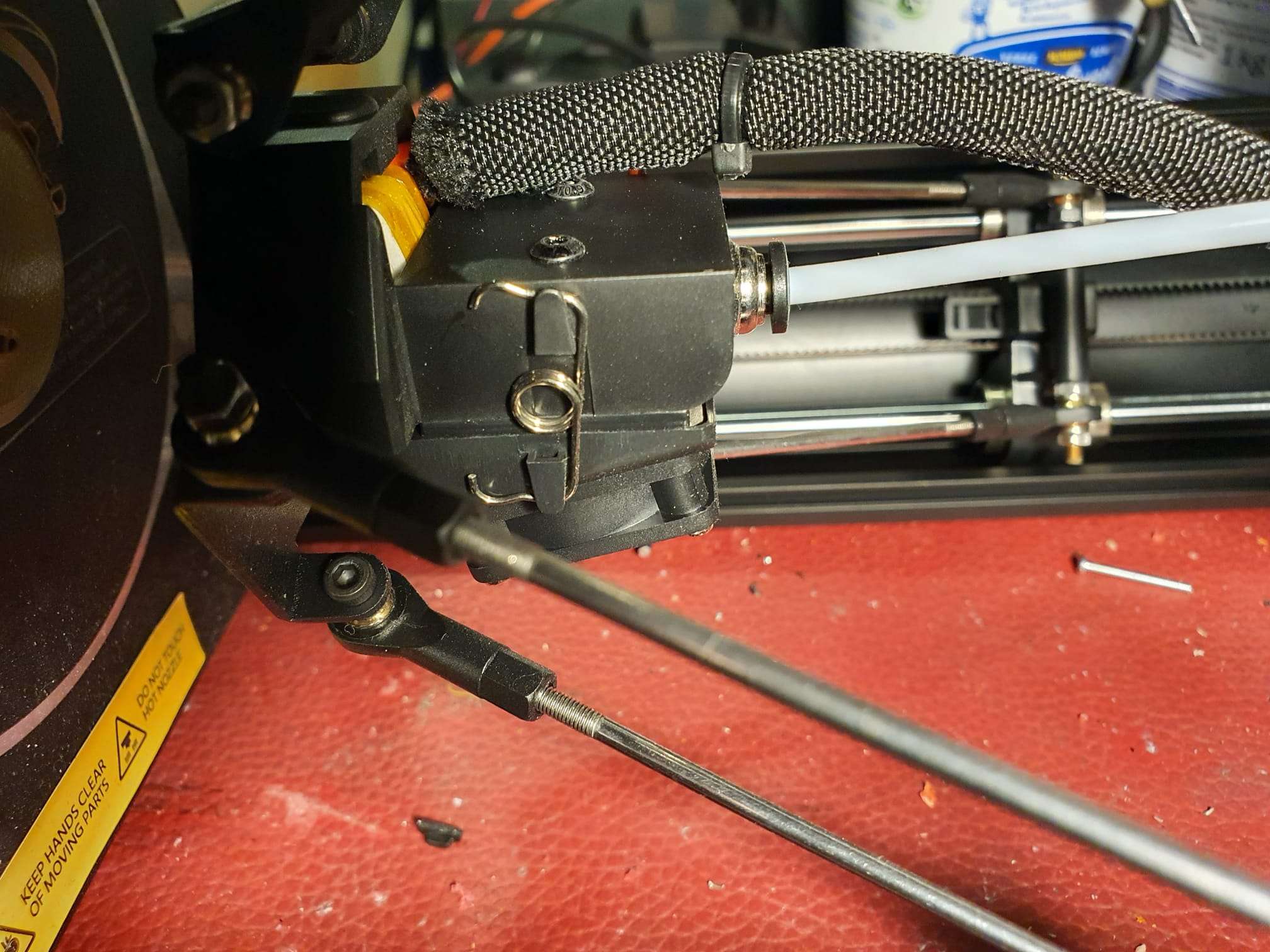
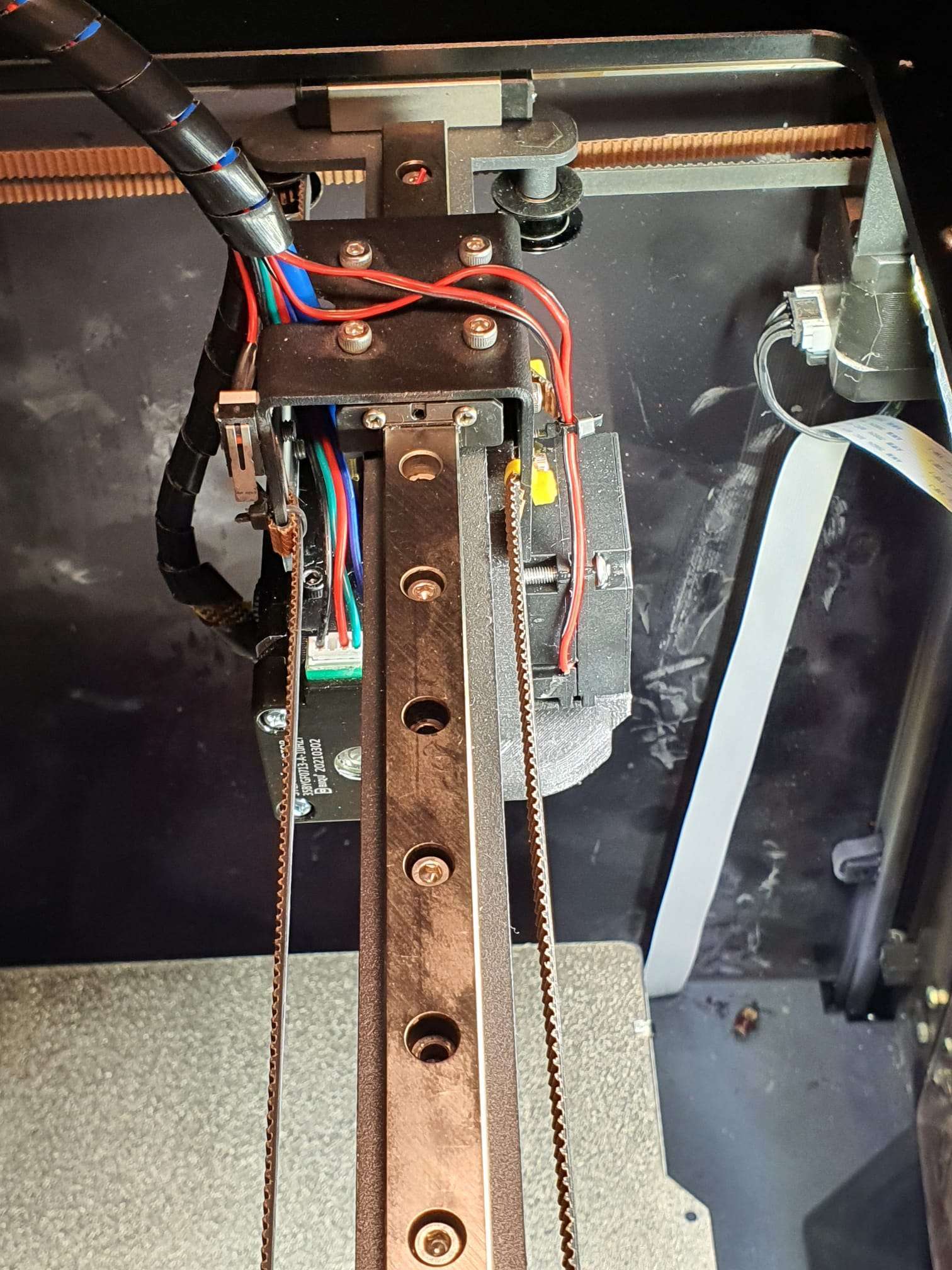
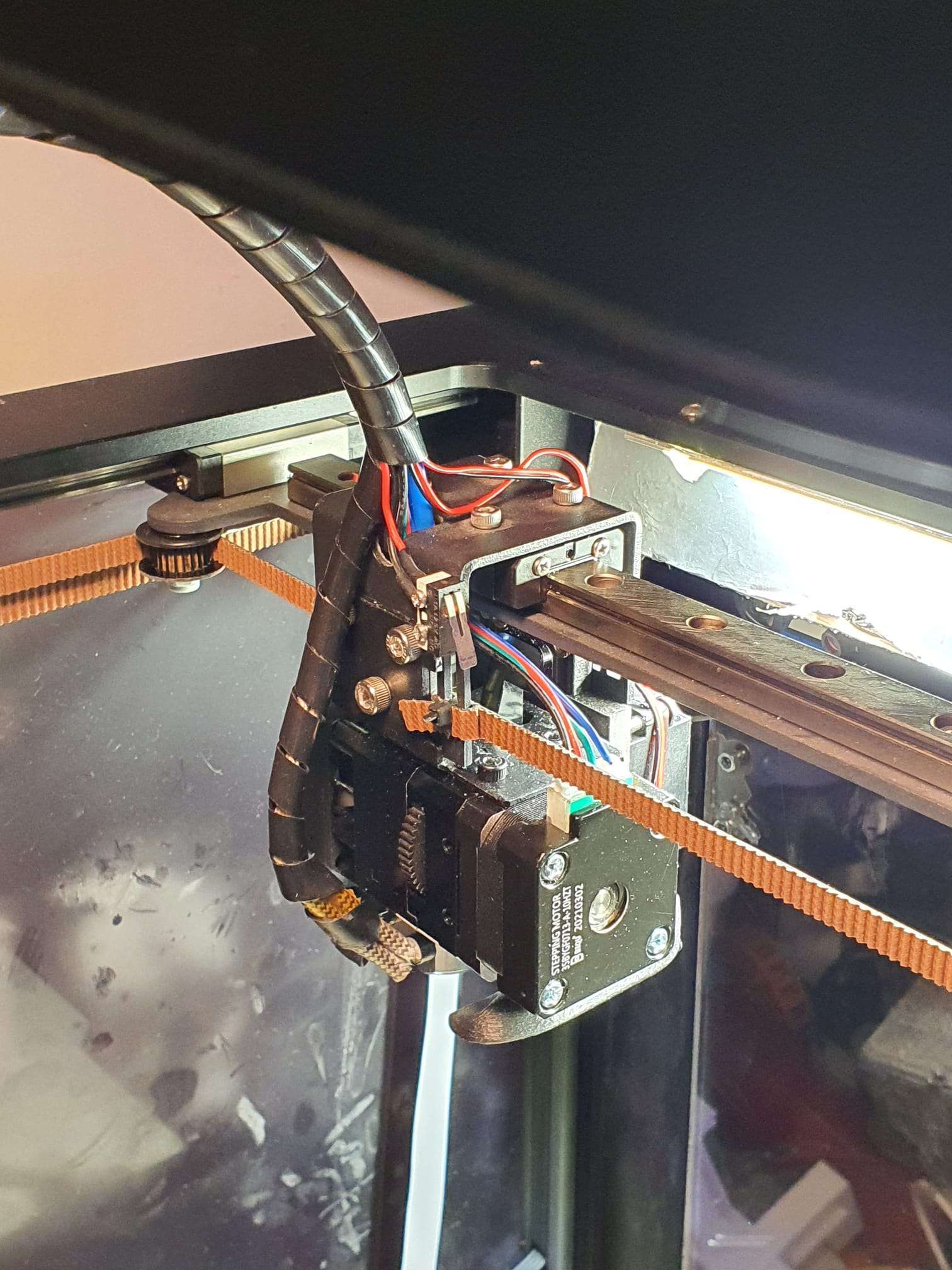
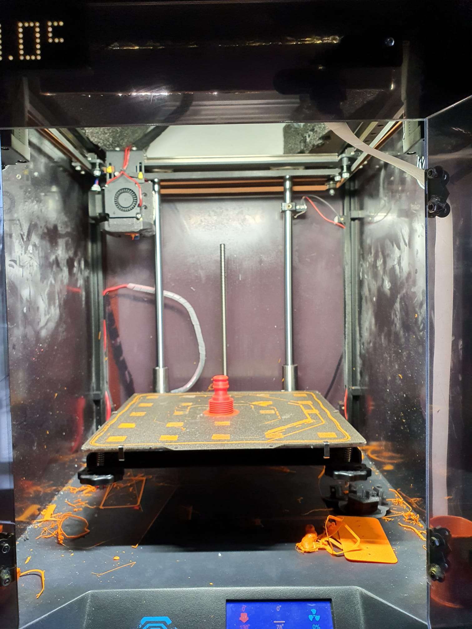
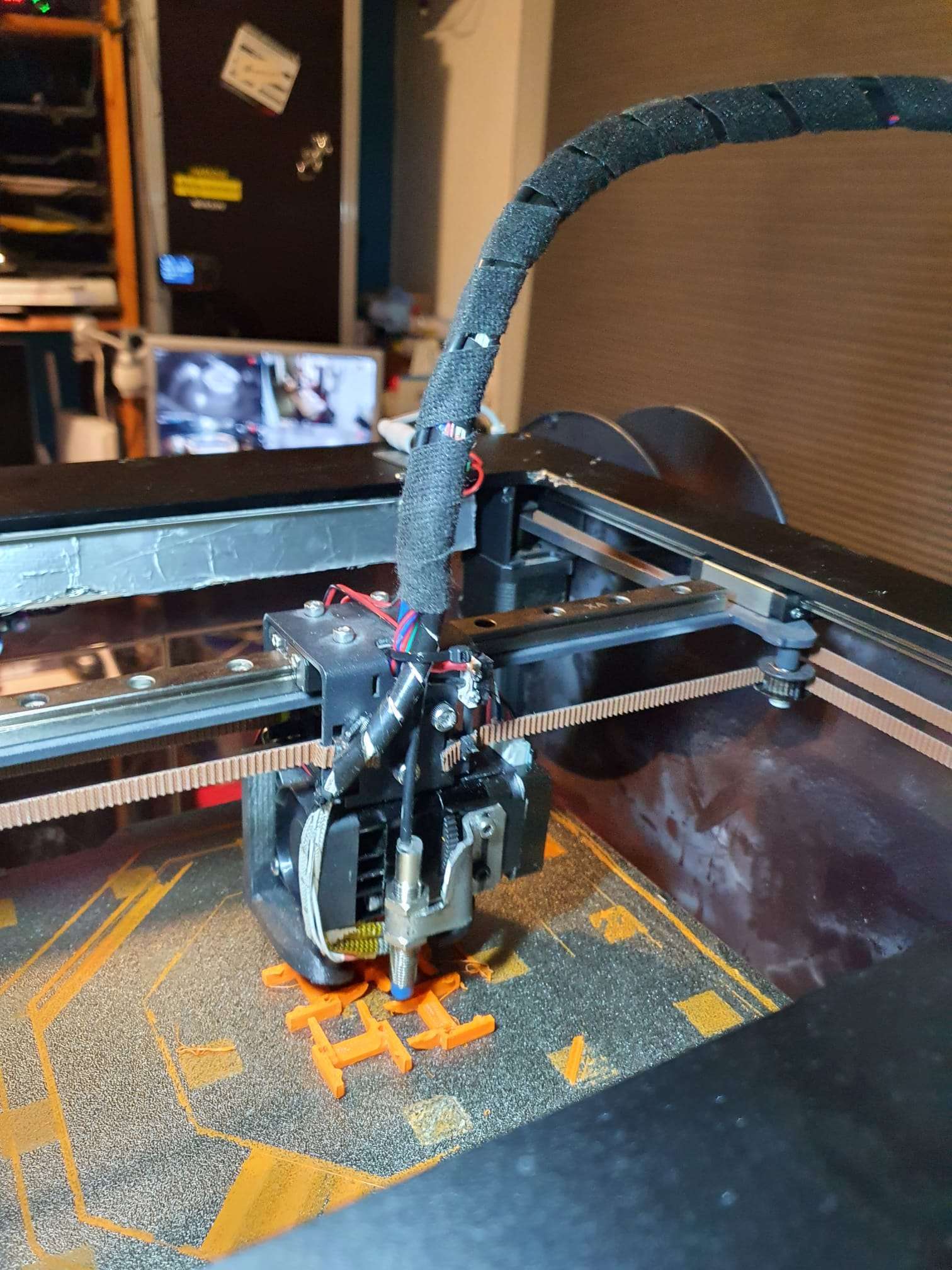
Today I opened the lid under my Monoprice Minidelta printer that I bought on Amazon end of last year (11-2021).

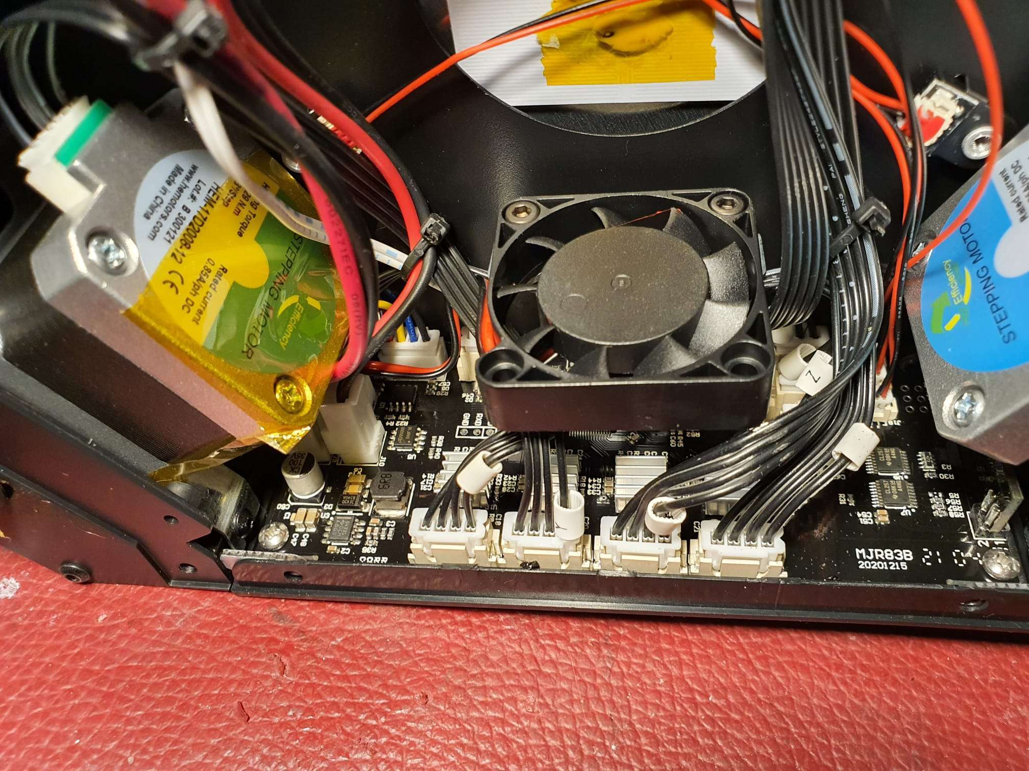
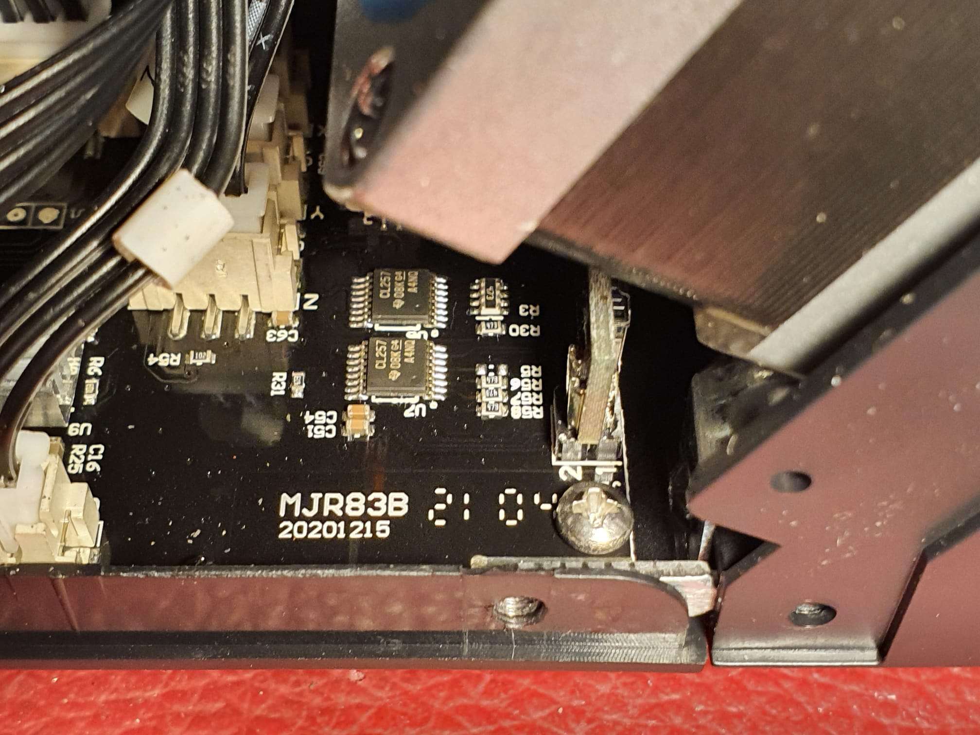
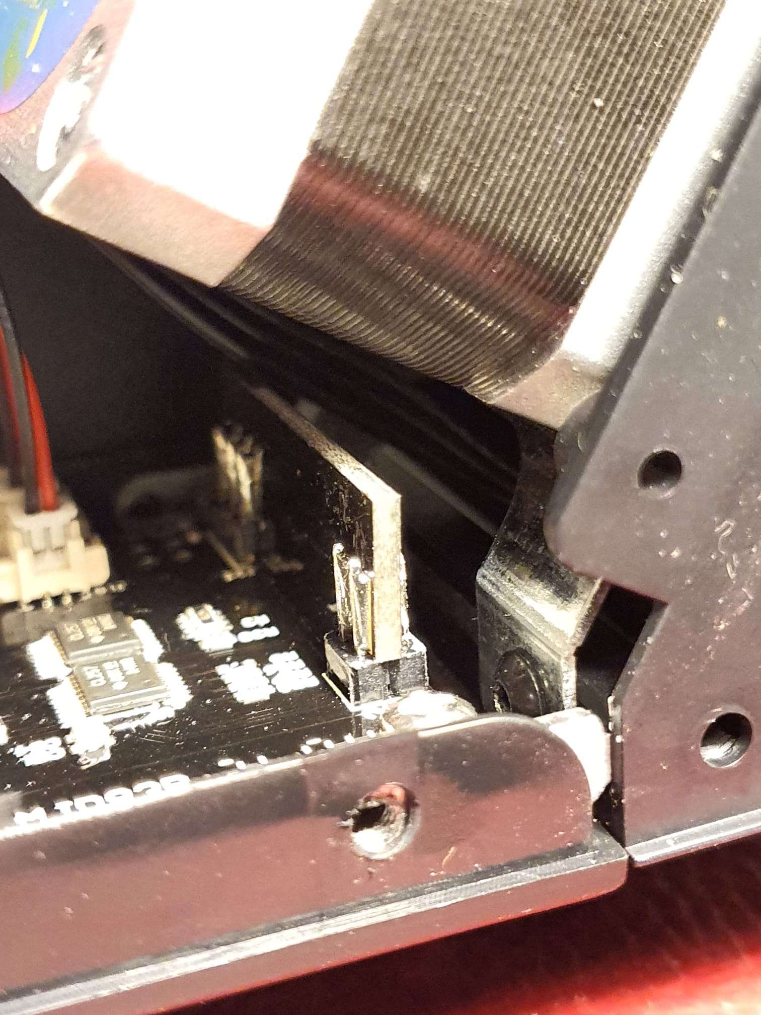
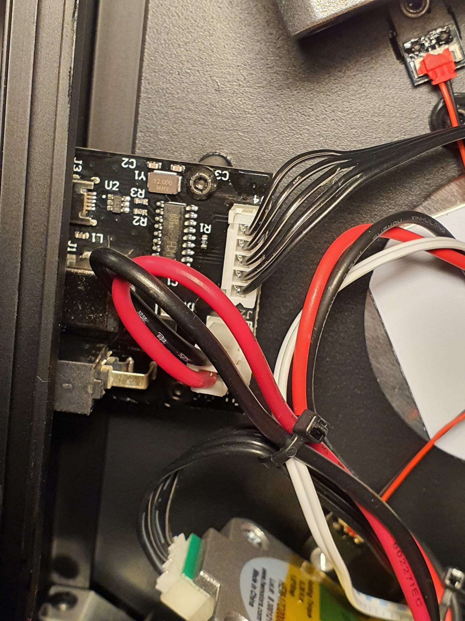
Unlike what I found on the net, I appear to have an upgraded motherboard that is joined with the TFT.

Both the MB and TFT have their own pocessor and -TFT update files, available from the Monoprice website and to be found on http://mpminideltav2.com/doku.php?id=octoprint:config.

The GD32F103 ARM processor is the 32-bits direct STM replacement and is a very capable processor.  The board also looks very good, so I won’t be replacing any of it.

I am however trying to build my own firmware for the MB, based on Marlin and the STM32 lookalike.  BUT- the LCD and the pin connections for the hardware ia all unknown to me, so it might take some more investigations..

For the short term, I will install a Pi Zero2 and adjecent PI IR camera in the printer, along with a top LED light.  The original new printer’s firmware allows the use of Octoprint so I can add this printer easily to my managed stock of remotely managed 3d printers.  Without modding the original firmware.

In the bottom of the printer, enough space is available to mount the RPI and I will switch the LED with the PI’s GPIO managed switches, and a MOSFET board.  Preferably with a PWM driver, or just on/off if this works better.

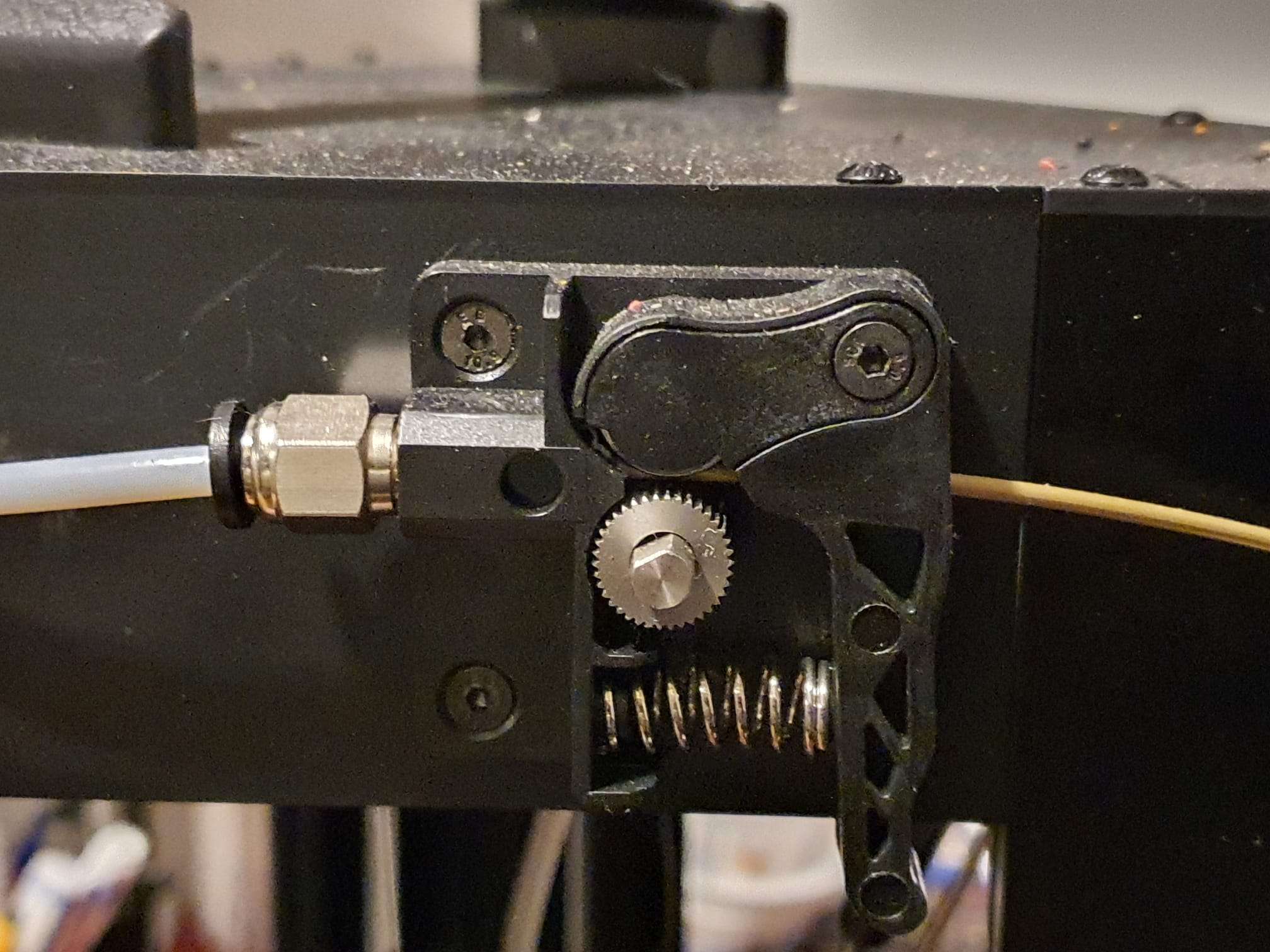
Another required upgrade will be to get a PEI sheet on the hotbed and replace the plasticy extruder with a dual drive one..

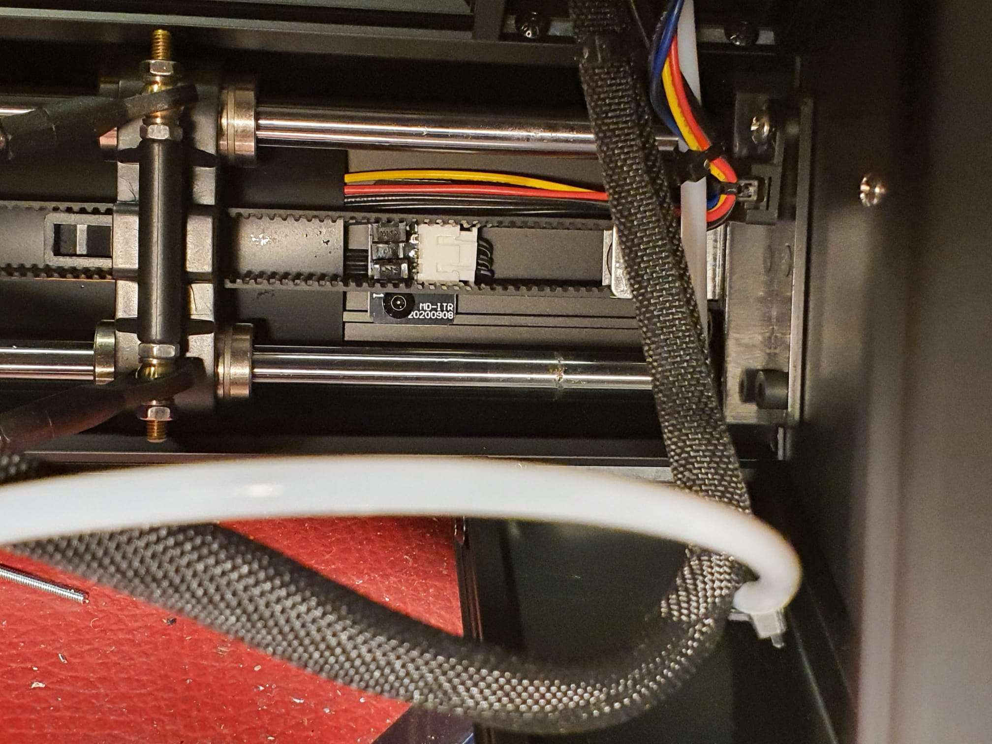
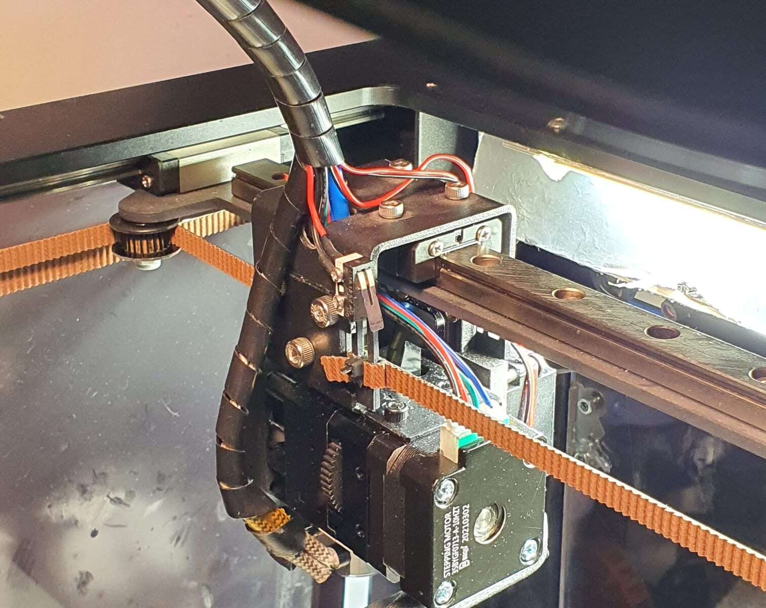
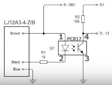
The optical Z+ endstops are OK!


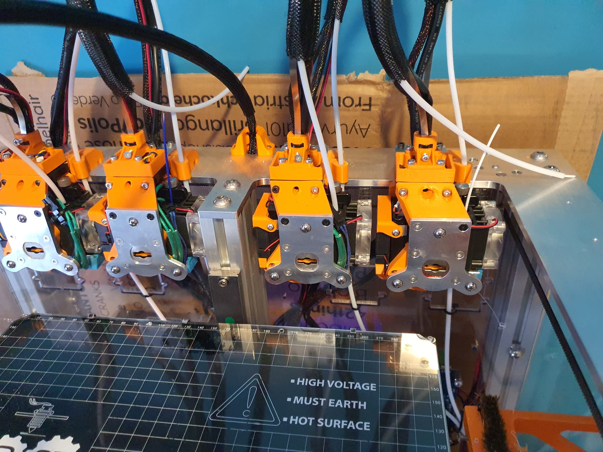
BTT BIQU H2 extruder in 2trees Spro

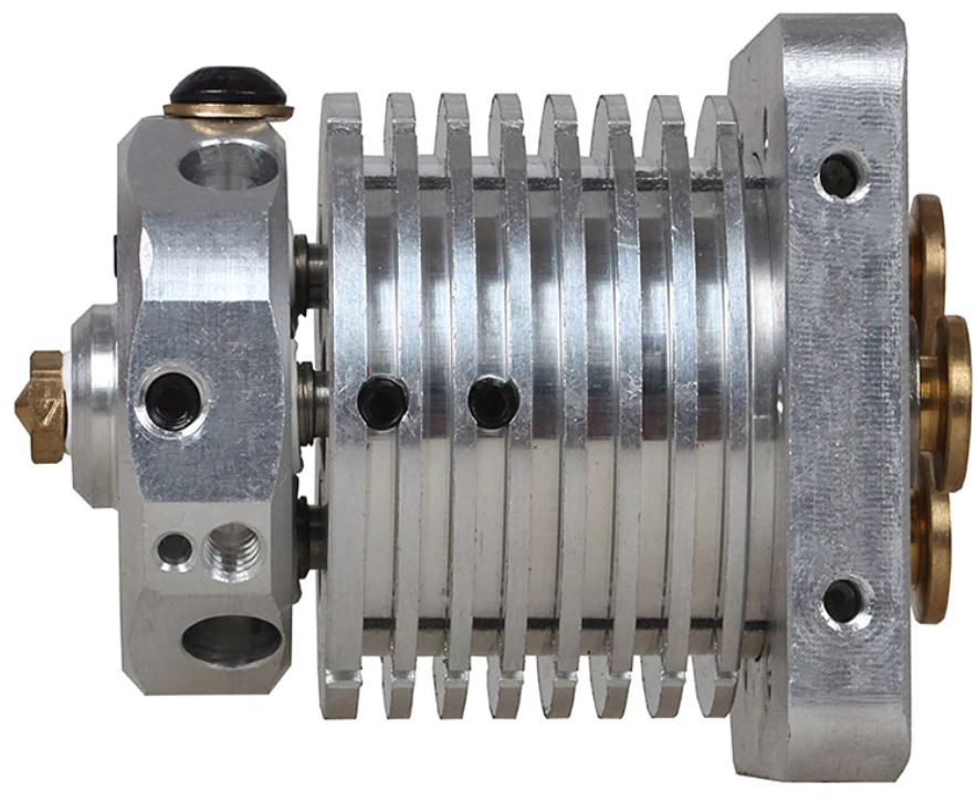
I bought a couple of BIQU H2 extruders to experiment with them.

The first printer I chose to mount this extruder is my TT Saphire pro.

I own this printer for a couple of years, and it behaves quite well.  But the original bowden setup is not my preferred setup, and the BIQUH2 seems very promising.

On the net, I found a 3d printable bracket with a seperate mount to re-use the 2 small 40mm side tool fans again as tool fans.

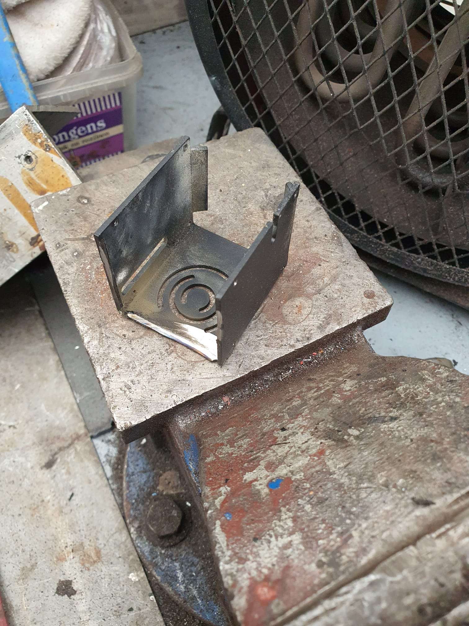
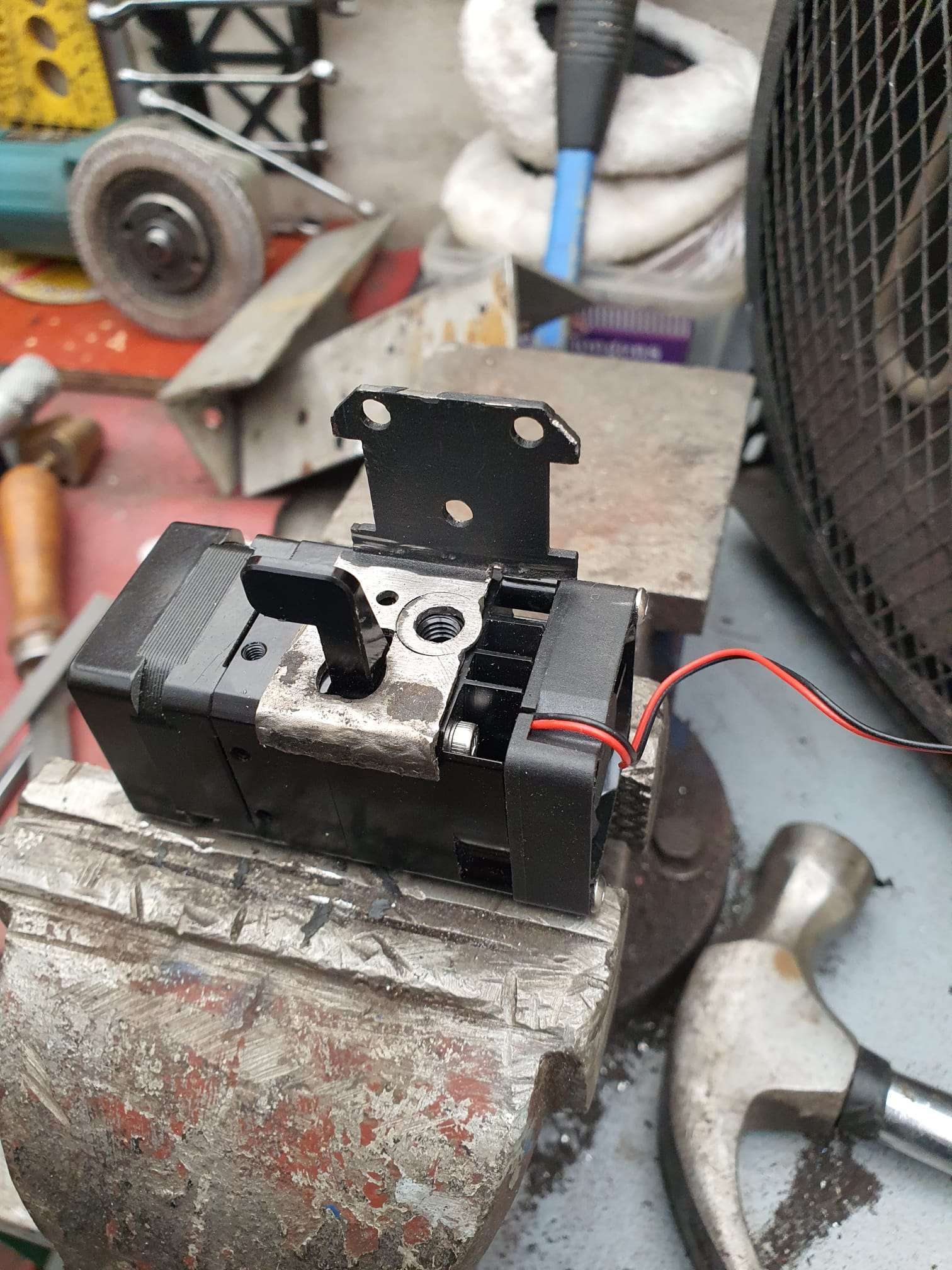
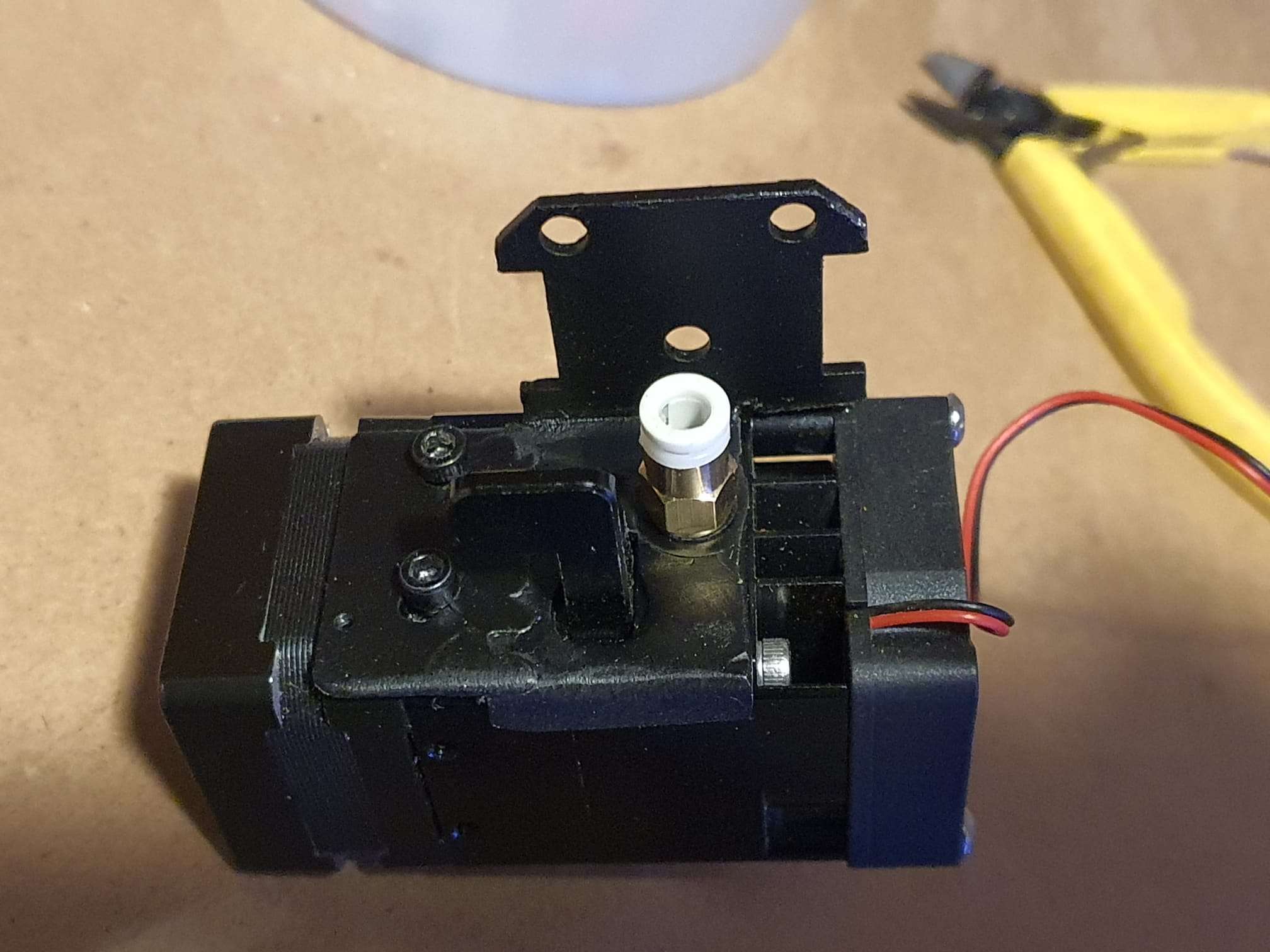
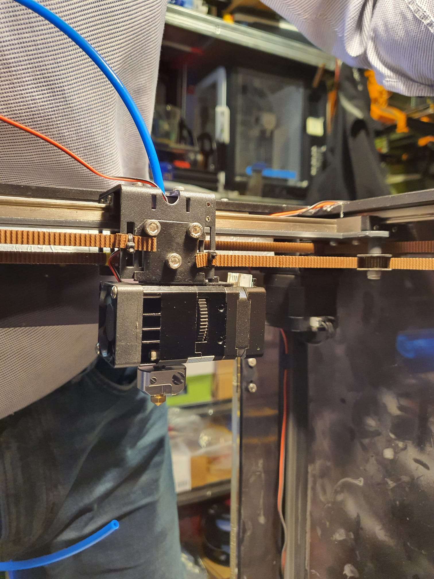
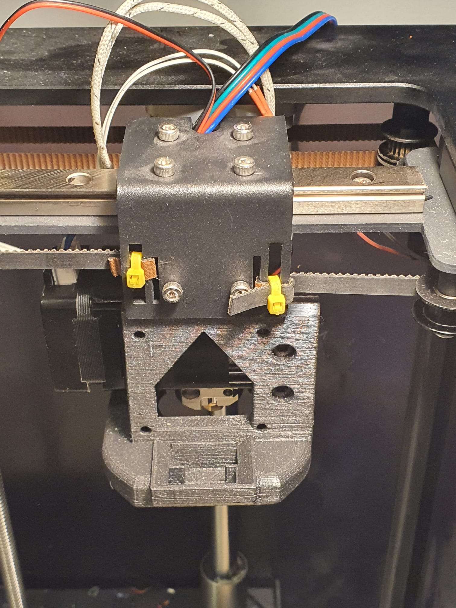
I ditched the 3d printed mount for the extruder and made me e steel one, from the old hotend mount.  That is what the pictures in this article will show.

The 3d printed toolfan mount is a bit modded because I have reversed the entire setup, so I will keep within the original specs of 235x235x200 mm printeble size.

For the rest, please see the pictures.  I re-used some of the old steel hotend mount, primarily the connecting plate with the XY carriage and the cornered horizontal plate.

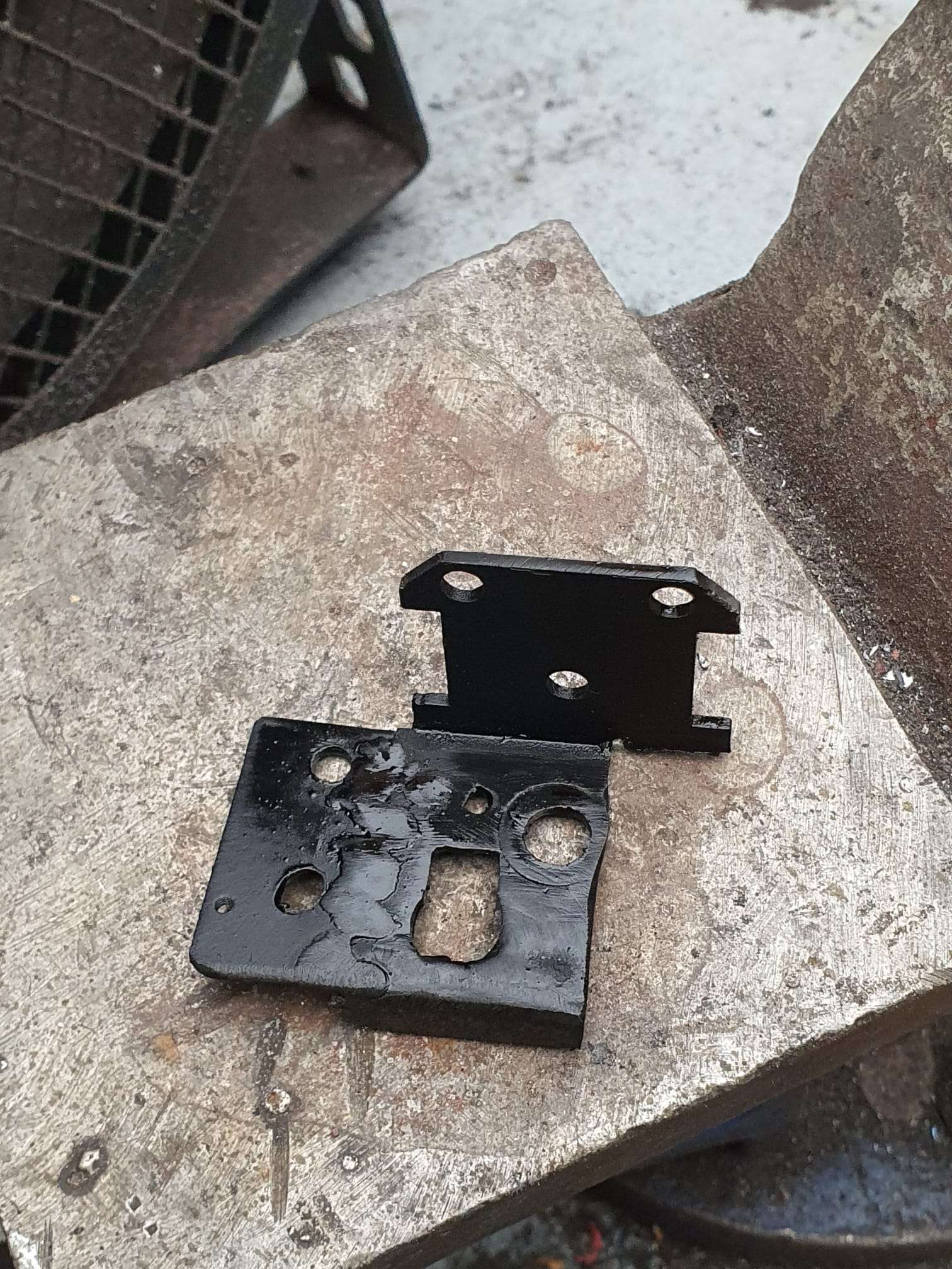
In the old big bowden tube hole I welded a 6mm inner- and  12mm outer dia ring in.

And I extended the horizontal base with a little piece of plate to use the 2 pieces 3mm threaded holes of the extruder’s upper side to bolt it all together.

The filament input of the extruder has a screw-in nut with a 4mm clamp for the ingoing 4mm tube, and this is the other mounting bolt to hold the extruder to the mount.

The original TT S pro hotend mount, freed from the parts I re-used to build the BIQU H2 mount.
Cut the re-used pice to size, took some material out for the lever and fitted the ring in the 12 mm hole, to be welded.
New mounting plate with welded ring at the right, and left an add-on welded little piece with the 2 holes for the mounting M3 screws.
Extruder mount ready
The first fit. My goal was to get the nozzle tip at exactly the same XY position as original. And that worked perfect!
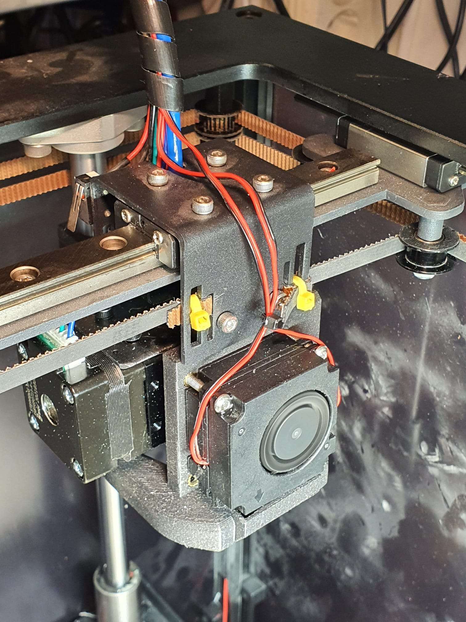
Mounted the toolfan holder. I modded this to be put INSIDE the carriage instead of on the outside.  I used 2 threaded M3 weld-in inserts in the toolfan holder.
Ready. The rear fan is reversed as intended. I took some material out of the holder to let the rear fan rotate freely, since it was not capable of this in the original setup.

And the inductive 8mm probe, at the rear of the extruder setup. Works perfect!

Upgrade Voron2.4 Octopi for Python3 with RPI/4b/4Gb and 2x SKR1.4 T

An upgrade to Python 3 is neccessary since Octoprint keeps mentioning at startup that future updates after 1.72 will no longer be supported when running a Python2 environment.

Since I made my Voron2.4 printer in 2018, this is still based on Python2.

I first followed the advice on the Octoprint website: Make a full backup from the RPI with the backup/restore plugin of Octoprint, save it to your local HDD.

Then, make a new image from Raspberry PI imager, selecting te most current Octopi image from the RPI imager’s menu.  Then, burn it on a micro SD card, take SD out and in again, change the wifi settings to whatever you have at home.  And,  put it in your Raspberry PI. Put the power on and wait some minutes. Search for your RPI with either bonjour os just use angry IP Scanner and find the local IP address.  Start PuTTY and login to the RPI with ‘pi’ username and ‘raspberry’ password.  Type ‘   ‘ and Enter. In the menu: Change the RPI’s login password to the one you used before and save it. Logout of PuTTY.

Now, login to octoprint with your browser at the identified local IP address and restore the locally saved backup.  This shoud take a long time to install. After this,  reboot and it should all work again.

BUT- it did not work at all.  Somehow either not all files are backupped and restored or I am missing some config settings.  Octoprint could not connect to the SKR4 boards, hence the LCD display did not work and without communnication to the boards, nothing could be done.  I tried to remedy the problem but after an hour or so I decided to go for a fresh re-install.

I did save the config file previously so with this and a fresh install I should be fine.

The rest of this post describes my search- and find- and is a HOW TO to help you do it right without any searching. Most of it is gathered from all these good sites where parts of the solution for ths specific configuration can be found and I just tied them together for the Voron2.4 with a Raspbery PI 4B and 4GB memory, with 2 x BTT SKR1.4T and a standard RGB LCD display connected with 2 block cabled wire connectors , the LCD also has a lit turning knob (see the pictures at the end of this post):

Installation

These instructions assume the software will run on a Raspberry Pi computer in conjunction with OctoPrint. It is recommended that a Raspberry Pi 2, 3, or 4 computer be used as the host machine (see the FAQ for other machines).

Klipper currently supports a number of Atmel ATmega based micro-controllers, ARM based micro-controllers, and Beaglebone PRU based printers.

Prepping an OS image

Start by installing OctoPi on the Raspberry Pi computer. Use OctoPi v0.17.0 or later – see the OctoPi releases for release information. One should verify that OctoPi boots and that the OctoPrint web server works. After connecting to the OctoPrint web page, follow the prompt to upgrade OctoPrint to v1.4.2 or later.

After installing OctoPi and upgrading OctoPrint, it will be necessary to ssh into the target machine to run a handful of system commands. If using a Linux or MacOS desktop, then the “ssh” software should already be installed on the desktop. There are free ssh clients available for other desktops (eg, PuTTY). Use the ssh utility to connect to the Raspberry Pi (ssh pi@octopi — password is “raspberry”) and run the following commands:

git clone https://github.com/Klipper3d/klipper

./klipper/scripts/install-octopi.sh

E: Repository ‘http://archive.raspberrypi.org/debian buster InRelease’ changed its ‘Suite’ value from ‘testing’ to ‘oldstable’

N: This must be accepted explicitly before updates for this repository can be applied. See apt-secure(8) manpage for details.

Omdat de repository veranderd is van “testing ” naar “stable” moet je eenmalig  toestemming geven om deze verandering in de repository te accepteren. Dit doe je met het volgende commando,

sudo apt-get update –allow-releaseinfo-change

Hierna kan je gewoon weer updaten met,

sudo  apt-get update

git clone https://github.com/Klipper3d/klipper

./klipper/scripts/install-octopi.sh


The above will download Klipper, install some system dependencies, setup Klipper to run at system startup, and start the Klipper host software. It will require an internet connection and it may take a few minutes to complete.

Building and flashing the micro-controller

To compile the micro-controller code, start by running these commands on the Raspberry Pi:

cd ~/klipper/

make menuconfig

Select the appropriate micro-controller and review any other options provided. Once configured, run:

make

It is necessary to determine the serial port connected to the micro-controller. For micro-controllers that connect via USB, run the following:

ls /dev/serial/by-id/*

It should report something similar to the following:

/dev/serial/by-id/usb-1a86_USB2.0-Serial-if00-port0

It’s common for each printer to have its own unique serial port name. This unique name will be used when flashing the micro-controller. It’s possible there may be multiple lines in the above output – if so, choose the line corresponding to the micro-controller (see the FAQ for more information).

For common micro-controllers, the code can be flashed with something similar to:

sudo service klipper stop

make flash FLASH_DEVICE=/dev/serial/by-id/usb-1a86_USB2.0-Serial-if00-port0

sudo service klipper start

Be sure to update the FLASH_DEVICE with the printer’s unique serial port name.

When flashing for the first time, make sure that OctoPrint is not connected directly to the printer (from the OctoPrint web page, under the “Connection” section, click “Disconnect”).

Configuring OctoPrint to use Klipper

The OctoPrint web server needs to be configured to communicate with the Klipper host software. Using a web browser, login to the OctoPrint web page and then configure the following items:

Navigate to the Settings tab (the wrench icon at the top of the page). Under “Serial Connection” in “Additional serial ports” add “/tmp/printer”. Then click “Save”.

Enter the Settings tab again and under “Serial Connection” change the “Serial Port” setting to “/tmp/printer”.

In the Settings tab, navigate to the “Behavior” sub-tab and select the “Cancel any ongoing prints but stay connected to the printer” option. Click “Save”.

From the main page, under the “Connection” section (at the top left of the page) make sure the “Serial Port” is set to “/tmp/printer” and click “Connect”. (If “/tmp/printer” is not an available selection then try reloading the page.)

Once connected, navigate to the “Terminal” tab and type “status” (without the quotes) into the command entry box and click “Send”. The terminal window will likely report there is an error opening the config file – that means OctoPrint is successfully communicating with Klipper. Proceed to the next section.

Configuring Klipper

The Klipper configuration is stored in a text file on the Raspberry Pi. Take a look at the example config files in the config directory. The Config Reference contains documentation on config parameters.

Arguably the easiest way to update the Klipper configuration file is to use a desktop editor that supports editing files over the “scp” and/or “sftp” protocols. There are freely available tools that support this (eg, Notepad++, WinSCP, and Cyberduck). Use one of the example config files as a starting point and save it as a file named “printer.cfg” in the home directory of the pi user (ie, /home/pi/printer.cfg).

Alternatively, one can also copy and edit the file directly on the Raspberry Pi via ssh – for example:

cp ~/klipper/config/example-cartesian.cfg ~/printer.cfg

nano ~/printer.cfg

Make sure to review and update each setting that is appropriate for the hardware.

It’s common for each printer to have its own unique name for the micro-controller. The name may change after flashing Klipper, so rerun the ls /dev/serial/by-id/* command and then update the config file with the unique name. For example, update the [mcu] section to look something similar to:

[mcu]

serial: /dev/serial/by-id/usb-1a86_USB2.0-Serial-if00-port0

After creating and editing the file it will be necessary to issue a “restart” command in the OctoPrint web terminal to load the config. A “status” command will report the printer is ready if the Klipper config file is successfully read and the micro-controller is successfully found and configured. It is not unusual to have configuration errors during the initial setup – update the printer config file and issue “restart” until “status” reports the printer is ready.

Klipper reports error messages via the OctoPrint terminal tab. The “status” command can be used to re-report error messages. The default Klipper startup script also places a log in /tmp/klippy.log which provides more detailed information.

In addition to common g-code commands, Klipper supports a few extended commands – “status” and “restart” are examples of these commands. Use the “help” command to get a list of other extended commands.

After Klipper reports that the printer is ready go on to the config check document to perform some basic checks on the pin definitions in the config file.


NEW:Rotation distance

Stepper motor drivers on Klipper require a rotation_distance parameter in each stepper config section. The rotation_distance is the amount of distance that the axis moves with one full revolution of the stepper motor. This document describes how one can configure this value.

Obtaining rotation_distance from steps_per_mm (or step_distance)

The designers of your 3d printer originally calculated steps_per_mm from a rotation distance. If you know the steps_per_mm then it is possible to use this general formula to obtain that original rotation distance:

rotation_distance = <full_steps_per_rotation> * <microsteps> / <steps_per_mm>

Or, if you have an older Klipper configuration and know the step_distance parameter you can use this formula:

rotation_distance = <full_steps_per_rotation> * <microsteps> * <step_distance>

The <full_steps_per_rotation> setting is determined from the type of stepper motor. Most stepper motors are “1.8 degree steppers” and therefore have 200 full steps per rotation (360 divided by 1.8 is 200). Some stepper motors are “0.9 degree steppers” and thus have 400 full steps per rotation. Other stepper motors are rare. If unsure, do not set full_steps_per_rotation in the config file and use 200 in the formula above.

The <microsteps> setting is determined by the stepper motor driver. Most drivers use 16 microsteps. If unsure, set microsteps: 16 in the config and use 16 in the formula above.

Almost all printers should have a whole number for rotation_distance on x, y, and z type axes. If the above formula results in a rotation_distance that is within .01 of a whole number then round the final value to that whole_number.

Calibrating rotation_distance on extruders

On an extruder, the rotation_distance is the amount of distance the filament travels for one full rotation of the stepper motor. The best way to get an accurate value for this setting is to use a “measure and trim” procedure.

First start with an initial guess for the rotation distance. This may be obtained from steps_per_mm or by inspecting the hardware.

Then use the following procedure to “measure and trim”:

  1. Make sure the extruder has filament in it, the hotend is heated to an appropriate temperature, and the printer is ready to extrude.
  2. Use a marker to place a mark on the filament around 70mm from the intake of the extruder body. Then use a digital calipers to measure the actual distance of that mark as precisely as one can. Note this as <initial_mark_distance>.
  3. Extrude 50mm of filament with the following command sequence: G91 followed by G1 E50 F60. Note 50mm as <requested_extrude_distance>. Wait for the extruder to finish the move (it will take about 50 seconds). It is important to use the slow extrusion rate for this test as a faster rate can cause high pressure in the extruder which will skew the results. (Do not use the “extrude button” on graphical front-ends for this test as they extrude at a fast rate.)
  4. Use the digital calipers to measure the new distance between the extruder body and the mark on the filament. Note this as <subsequent_mark_distance>. Then calculate: actual_extrude_distance = <initial_mark_distance> – <subsequent_mark_distance>
  5. Calculate rotation_distance as: rotation_distance = <previous_rotation_distance> * <actual_extrude_distance> / <requested_extrude_distance> Round the new rotation_distance to three decimal places.

If the actual_extrude_distance differs from requested_extrude_distance by more than about 2mm then it is a good idea to perform the steps above a second time.

Note: Do not use a “measure and trim” type of method to calibrate x, y, or z type axes. The “measure and trim” method is not accurate enough for those axes and will likely lead to a worse configuration. Instead, if needed, those axes can be determined by measuring the belts, pulleys, and lead screw hardware.

Obtaining rotation_distance by inspecting the hardware

It’s possible to calculate rotation_distance with knowledge of the stepper motors and printer kinematics. This may be useful if the steps_per_mm is not known or if designing a new printer.

Belt driven axes

It is easy to calculate rotation_distance for a linear axis that uses a belt and pulley.

First determine the type of belt. Most printers use a 2mm belt pitch (that is, each tooth on the belt is 2mm apart). Then count the number of teeth on the stepper motor pulley. The rotation_distance is then calculated as:

rotation_distance = <belt_pitch> * <number_of_teeth_on_pulley>

For example, if a printer has a 2mm belt and uses a pulley with 20 teeth, then the rotation distance is 40.

Axes with a lead screw

It is easy to calculate the rotation_distance for common lead screws using the following formula:

rotation_distance = <screw_pitch> * <number_of_separate_threads>

For example, the common “T8 leadscrew” has a rotation distance of 8 (it has a pitch of 2mm and has 4 separate threads).

Older printers with “threaded rods” have only one “thread” on the lead screw and thus the rotation distance is the pitch of the screw. (The screw pitch is the distance between each groove on the screw.) So, for example, an M6 metric rod has a rotation distance of 1 and an M8 rod has a rotation distance of 1.25.

Extruder

It’s possible to obtain an initial rotation distance for extruders by measuring the diameter of the “hobbed bolt” that pushes the filament and using the following formula: rotation_distance = <diameter> * 3.14

If the extruder uses gears then it will also be necessary to determine and set the gear_ratio for the extruder.

The actual rotation distance on an extruder will vary from printer to printer, because the grip of the “hobbed bolt” that engages the filament can vary. It can even vary between filament spools. After obtaining an initial rotation_distance, use the measure and trim procedure to obtain a more accurate setting.

Using a gear_ratio

Setting a gear_ratio can make it easier to configure the rotation_distance on steppers that have a gear box (or similar) attached to it. Most steppers do not have a gear box – if unsure then do not set gear_ratio in the config.

When gear_ratio is set, the rotation_distance represents the distance the axis moves with one full rotation of the final gear on the gear box. If, for example, one is using a gearbox with a “5:1” ratio, then one could calculate the rotation_distance with knowledge of the hardware and then add gear_ratio: 5:1 to the config.

For gearing implemented with belts and pulleys, it is possible to determine the gear_ratio by counting the teeth on the pulleys. For example, if a stepper with a 16 toothed pulley drives the next pulley with 80 teeth then one would use gear_ratio: 80:16. Indeed, one could open a common off the shelf “gear box” and count the teeth in it to confirm its gear ratio.

Note that sometimes a gearbox will have a slightly different gear ratio than what it is advertised as. The common BMG extruder motor gears are an example of this – they are advertised as “3:1” but actually use “50:17” gearing. (Using teeth numbers without a common denominator may improve overall gear wear as the teeth don’t always mesh the same way with each revolution.) The common “5.18:1 planetary gearbox”, is more accurately configured with gear_ratio: 57:11.

If several gears are used on an axis then it is possible to provide a comma separated list to gear_ratio. For example, a “5:1” gear box driving a 16 toothed to 80 toothed pulley could use gear_ratio: 5:1, 80:16.

In most cases, gear_ratio should be defined with whole numbers as common gears and pulleys have a whole number of teeth on them. However, in cases where a belt drives a pulley using friction instead of teeth, it may make sense to use a floating point number in the gear ratio (eg, gear_ratio: 107.237:16).

For a Voron 2.4 (300x300x300) setup, start settings are pre-defined:

To add in the config file:


NOT in the TMC settings, just in the stepper_x, and so on

And delete the old commands: step_distance: 0.0125 or just comment them out as I did initially..

Add for steppers X,Y

rotation_distance: 40

## gear_ratio: 1:1

microsteps: 16


and for Z-Z3:

rotation_distance: 40

gear_ratio: 80:16

microsteps: 16


Add for extruder stepper:

##  Update value below when you perform extruder calibration

##  If you ask for 100mm of filament, but in reality it is 98mm:

##  rotation_distance = <previous_rotation_distance> * <actual_extrude_distance> / 100

##  22.6789511 is a good starting point

rotation_distance: 22.6789511   #Bondtech 5mm Drive Gears

##  Update Gear Ratio depending on your Extruder Type

##  Use 50:17 for Afterburner/Clockwork (BMG Gear Ratio)

##  Use 80:20 for M4, M3.1

gear_ratio: 50:17               #BMG Gear Ratio

microsteps: 16

full_steps_per_rotation: 200    #200 for 1.8 degree, 400 for 0.9 degree

nozzle_diameter: 0.400 # or 0.6 like I have

filament_diameter: 1.75


Send: M876 P1

Recv: // mcu ‘mcu’: Command format mismatch: config is_config=%c crc=%u is_shutdown=%c move_count=%hu vs config is_config=%c crc=%u move_count=%hu is_shutdown=%c

Recv: //

Recv: // This type of error is frequently caused by running an older

Recv: // version of the firmware on the micro-controller (fix by

Recv: // recompiling and flashing the firmware).

Recv: //

Recv: // Known versions: host=v0.10.0-184-gdd714fc7, mcu=v0.9.1-319-g3233ec08-20210315_134213-octopi, z=v0.9.1-319-g3233ec08-20210315_134213-octopi

Recv: //

Recv: // Once the underlying issue is corrected, use the “RESTART”

Recv: // command to reload the config and restart the host software.

Recv: // Protocol error connecting to printer

Recv: !! mcu ‘mcu’: Command format mismatch: config is_config=%c crc=%u is_shutdown=%c move_count=%hu vs config is_config=%c crc=%u move_count=%hu is_shutdown=%c


So, flash both SKR1.4 T’s with the new firmware  (download this from the PI4) and start trhem first without USB connection to the RPI. Then, shutdown (=POWER OFF) and connect the USB cables and start up again.

Now, Octopi will fire up and the LCD runs again, and all is connected.

Do the checks as described further on.


My printer.cfg working Voron2.4 config file AFTER the Python 3 upgrade:


##

## Voron Design VORON2.4 310mm SKR 1.4turbo x 2 with TMC2209 UART config

# March 15th, 2021 Jantec.nl


# To solve the issue of varying Z height after G32: Add this: relative_reference_index: (add a point number of bed_mesh here)

# must be added to get a coupling between the initial G28’s Z probe position

# and bed mesh level’s Z probe value at a specified mesh bed level point.  I will try to use the point that is exactly at the switch position,

# so I can also get a predefined measured Z value for the Z position’s offset in G28.


[mcu]

##——————————————————————–

serial: /dev/serial/by-path/platform-fd500000.pcie-pci-0000:01:00.0-usb-0:1.4:1.0

##——————————————————————–

[mcu z]

##——————————————————————–

serial: /dev/serial/by-path/platform-fd500000.pcie-pci-0000:01:00.0-usb-0:1.3:1.0

##——————————————————————–


[printer]

kinematics: corexy

max_velocity: 300

max_accel: 1000                                  #Max 4000

max_z_velocity: 18                               #Max 15 for 12V TMC Drivers, can increase for 24V

max_z_accel: 350                                #Max ?

square_corner_velocity: 5.0  #Can experiment with 8.0, default 5.0


#####################################################################

#          X/Y Stepper Settings

#####################################################################


[stepper_x]

##        Connected to X on mcu_xye (B Motor)

step_pin: P2.2

dir_pin: !P2.6

microsteps: 16

rotation_distance: 40

## gear_ratio: 80:16

enable_pin: !P2.1

## step_distance: 0.0125

endstop_pin: P1.29


##——————————————————————–

## X Settings for 300mm build

position_min: 0

position_endstop: 300

position_max:300

##——————————————————————–

homing_speed: 150   #Max 100 was 25

homing_retract_dist: 5

homing_positive_dir: true


##        Make sure to update below for your relevant driver (2208 or 2209)

[tmc2209 stepper_x]

uart_pin: P1.10

interpolate: True

run_current: 1.0

hold_current: 0.7

sense_resistor: 0.110

stealthchop_threshold: 0


[stepper_y]

##        Connected to Y on mcu_xye (A Motor)

step_pin: P0.19

dir_pin: !P0.20

enable_pin: !P2.8

rotation_distance: 40

## gear_ratio: 80:16

microsteps: 16

## step_distance: 0.0125

endstop_pin: P1.28


##——————————————————————–

## Y Settings for 300mm build

position_min: 0

position_endstop: 305

position_max: 305

##——————————————————————–

homing_speed: 150  #Max 100 was 25

homing_retract_dist: 5

homing_positive_dir: true


##        Make sure to update below for your relevant driver (2208 or 2209)

[tmc2209 stepper_y]

uart_pin: P1.9

interpolate: True

run_current: 1.0

hold_current: 0.7

sense_resistor: 0.110

stealthchop_threshold: 0


#####################################################################

#          Z Stepper Settings

#####################################################################


## Z MCU – In X Position

## Z0 Stepper – Front Left

[stepper_z]

step_pin: z:P2.2

dir_pin: !z:P2.6

enable_pin: !z:P2.1

rotation_distance: 40

gear_ratio: 80:16

microsteps: 16

## step_distance: 0.00250

# endstop_pin: z:P1.27 # this is the switch’s  physical connection,

# not any longer used due to problems when filament is still hanging on the nozzle

# position_endstop:  0  # no longer required


endstop_pin: probe:z_virtual_endstop


##——————————————————————–

## Z Settings for 300mm build

position_max: 300

position_min:-2

##——————————————————————–

homing_speed: 15   #was 15

second_homing_speed: 3.0

homing_retract_dist: 5.0

homing_positive_dir: false


##        Make sure to update below for your relevant driver (2208 or 2209)

[tmc2209 stepper_z]

uart_pin: z:P1.10

interpolate: true

run_current: 1.0

hold_current: 0.8

sense_resistor: 0.110

stealthchop_threshold: 0


##        Z MCU – In Y Position

##        Z1 Stepper – Rear Left

[stepper_z1]

step_pin: z:P0.19

dir_pin: z:P0.20

enable_pin: !z:P2.8

rotation_distance: 40

gear_ratio: 80:16

microsteps: 16

## step_distance: 0.00250


##        Make sure to update below for your relevant driver (2208 or 2209)

[tmc2209 stepper_z1]

uart_pin: z:P1.9

interpolate: true

run_current: 1.0

hold_current: 0.8

sense_resistor: 0.110

stealthchop_threshold: 0


##        Z MCU – In Z Position

##        Z2 Stepper – Rear Right

[stepper_z2]

step_pin: z:P0.22

dir_pin: !z:P2.11

enable_pin: !z:P0.21

rotation_distance: 40

gear_ratio: 80:16

microsteps: 16

## step_distance: 0.00250


##        Make sure to update below for your relevant driver (2208 or 2209)

[tmc2209 stepper_z2]

uart_pin: z:P1.8

interpolate: true

run_current: 1.0

hold_current: 0.80

sense_resistor: 0.110

stealthchop_threshold: 0


##        Z MCU – In E0 Position

##        Z3 Stepper – Front Right

[stepper_z3]

step_pin: z:P2.13

dir_pin: z:P0.11

enable_pin: !z:P2.12

rotation_distance: 40

gear_ratio: 80:16

microsteps: 16

## step_distance: 0.00250


##        Make sure to update below for your relevant driver (2208 or 2209)

[tmc2209 stepper_z3]

uart_pin: z:P1.4

interpolate: true

run_current: 1.0

hold_current: 0.80

sense_resistor: 0.110

stealthchop_threshold: 0


#####################################################################

#          Extruder

#####################################################################


#          E0 on MCU X/Y

[extruder]

step_pin: P2.13

dir_pin: !P0.11

enable_pin: !P2.12


## NEW:

##  Update value below when you perform extruder calibration

##  If you ask for 100mm of filament, but in reality it is 98mm:

##  rotation_distance = <previous_rotation_distance> * <actual_extrude_distance> / 100

##  22.6789511 is a good starting point

rotation_distance: 22.6789511   #Bondtech 5mm Drive Gears

##  Update Gear Ratio depending on your Extruder Type

##  Use 50:17 for Afterburner/Clockwork (BMG Gear Ratio)

##  Use 80:20 for M4, M3.1

gear_ratio: 50:17               #BMG Gear Ratio

microsteps: 16

full_steps_per_rotation: 200    #200 for 1.8 degree, 400 for 0.9 degree

## nozzle_diameter: 0.400

## filament_diameter: 1.75


##        16 microsteps Mobius 3 ~= 0.00180

##        Update value below when you perform extruder calibration

##        Higher value means less filament extruded

##        If you ask for 100mm of filament, but in reality it is 98mm:

##        step_distance = 98 / 100 * step_distance_old

##  0.00240 a good starting value for Afterburner, 0.00180 for Mobius

## step_distance: 0.0022

nozzle_diameter: 0.600

filament_diameter: 1.75


heater_pin: P2.7

##        Validate the following thermistor type to make sure it is correct


## For SKR V1.4 and PT100 with MAX31865:

sensor_type: MAX31865

sensor_pin: P1.1

spi_speed: 4000000

spi_software_sclk_pin: P0.4

spi_software_mosi_pin: P1.17

spi_software_miso_pin: P0.5

rtd_nominal_r: 100

rtd_reference_r: 430

rtd_num_of_wires: 2


## If you are in EU or other 50hz country, add this line: THIS CAUSES HANGING of the display!

#rtd_use_50Hz_filter: True  THIS DOES NOT WORK WELL


#sensor_type: ATC Semitec 104GT-2

## (is normal NTC for hotbed with normal sensor_pin: P0.24)

#sensor_pin: P0.24


min_temp: 10

max_temp: 300

max_power: 1

min_extrude_temp: 170


#control = pid   #PID parameters: pid_Kp=22.661 pid_Ki=1.064 pid_Kd=120.670, without silicon sock

#pid_kp = 26.213

#pid_ki = 1.304

#pid_kd = 131.721

##        Try to keep pressure_advance below 1.0

pressure_advance: 0.08

##        Default is 0.040, leave stock

pressure_advance_smooth_time: 0.040


#####################################################################

##        E0 on MCU X/Y

##        Make sure to update below for your relevant driver (2208 or 2209)

[tmc2209 extruder]

uart_pin: P1.4

interpolate: false

run_current: 0.45   # was 0.6

hold_current: 0.2  # was 0.2

sense_resistor: 0.110

stealthchop_threshold: 0


[verify_heater extruder]

max_error: 220

#   The maximum “cumulative temperature error” before raising an

#   error. Smaller values result in stricter checking and larger

#   values allow for more time before an error is reported.

#   Specifically, the temperature is inspected once a second and if it

#   is close to the target temperature then an internal “error

#   counter” is reset; otherwise, if the temperature is below the

#   target range then the counter is increased by the amount the

#   reported temperature differs from that range. Should the counter

#   exceed this “max_error” then an error is raised. The default is

#   120.

#check_gain_time:

#   This controls heater verification during initial heating. Smaller

#   values result in stricter checking and larger values allow for

#   more time before an error is reported. Specifically, during

#   initial heating, as long as the heater increases in temperature

#   within this time frame (specified in seconds) then the internal

#   “error counter” is reset. The default is 20 seconds for extruders

#   and 60 seconds for heater_bed.

hysteresis: 15

#   The maximum temperature difference (in Celsius) to a target

#   temperature that is considered in range of the target. This

#   controls the max_error range check. It is rare to customize this

#   value. The default is 5.

#heating_gain: 2

#   The minimum temperature (in Celsius) that the heater must increase

#   by during the check_gain_time check. It is rare to customize this

#   value. The default is 2.


#####################################################################

#          Filament sensor switch on E0 switch input

#####################################################################


# This still needs a script to work properly, a runout_gcode and a return or recover gcode in the sys directory including the correct calls for it..


[filament_switch_sensor my_sensor]

#proved not to work Beh could throw my 6 hrs print away

pause_on_runout: True

#   When set to True, a PAUSE will execute immediately after a runout

#   is detected. Note that if pause_on_runout is False and the

#   runout_gcode is omitted then runout detection is disabled. Default

#   is True.

#runout_gcode:

#   A list of G-Code commands to execute after a filament runout is

#   detected. See docs/Command_Templates.md for G-Code format. If

#   pause_on_runout is set to True this G-Code will run after the

#   PAUSE is complete. The default is not to run any G-Code commands.

#insert_gcode:

#   A list of G-Code commands to execute after a filament insert is

#   detected. See docs/Command_Templates.md for G-Code format. The

#   default is not to run any G-Code commands, which disables insert

#   detection.

#event_delay: 3.0

#   The minimum amount of time in seconds to delay between events.

#   Events triggered during this time period will be silently

#   ignored. The default is 3 seconds.

#pause_delay: 0.5

#   The amount of time to delay, in seconds, between the pause command

#   dispatch and execution of the runout_gcode. It may be useful to

#   increase this delay if OctoPrint exhibits strange pause behavior.

#   Default is 0.5 seconds.

switch_pin: P1.26

#   The pin on which the switch is connected. This parameter must be

#   provided.


#


#####################################################################

#          Bed Heater

#####################################################################


[heater_bed]

##        SSR Pin – Z board, Fan Pin

heater_pin: z:P2.3

sensor_type: NTC 100K MGB18-104F39050L32

sensor_pin: z:P0.25

##        Adjust Max Power so your heater doesn’t warp your bed

max_power: 0.5  # was 0.6 for 230V 500 Watt, which is hardware switchable to rech fast 110 deg…

# the 24V wide 310x310mm bed heater is primary and does not warp the bed as the 230V one does!

min_temp: 0

max_temp: 140

#control: watermark


[verify_heater heater_bed]

max_error: 300

#   The maximum “cumulative temperature error” before raising an

#   error. Smaller values result in stricter checking and larger

#   values allow for more time before an error is reported.

#   Specifically, the temperature is inspected once a second and if it

#   is close to the target temperature then an internal “error

#   counter” is reset; otherwise, if the temperature is below the

#   target range then the counter is increased by the amount the

#   reported temperature differs from that range. Should the counter

#   exceed this “max_error” then an error is raised. The default is

#   120.

check_gain_time:200

#   This controls heater verification during initial heating. Smaller

#   values result in stricter checking and larger values allow for

#   more time before an error is reported. Specifically, during

#   initial heating, as long as the heater increases in temperature

#   within this time frame (specified in seconds) then the internal

#   “error counter” is reset. The default is 20 seconds for extruders

#   and 60 seconds for heater_bed.

hysteresis: 5

#   The maximum temperature difference (in Celsius) to a target

#   temperature that is considered in range of the target. This

#   controls the max_error range check. It is rare to customize this

#   value. The default is 5.

heating_gain: 1

#   The minimum temperature (in Celsius) that the heater must increase

#   by during the check_gain_time check. It is rare to customize this

#   value. The default is 2.


##FIND YOUR OWN: “PID_CALIBRATE HEATER=heater_bed TARGET=60” to run autotune on the bed at 90 degrees C for 5 cycles.


#####################################################################

#          Z-Probe

#####################################################################


[probe]

##        Inductive Probe

##        This probe is not used for Z height, only Quad Gantry Leveling

##        Z_MAX on mcu_z

##        If your probe is NO instead of NC, add change pin to !z:P0.10

pin: z:P0.10  # add ^ for pull-up if needed ^z:P0.10


x_offset: 0

y_offset: 25.0                                       # must be 25

#z_offset: 5.3                                                   # trigger height versus nozzle height measured 5.4  is autotuned

speed: 5                                                                      # max 5

samples: 1                                                       #was 3 or 5

samples_result: median

sample_retract_dist: 10                        # was 15, set this higher for more switching distance

samples_tolerance: 0.06                       # was 0.006

samples_tolerance_retries: 2     # was 5


#####################################################################

#          Fan Control

#####################################################################


[heater_fan hotend_fan]

##        Hotend Fan – XYE board, HE1 Connector

pin: P2.4

max_power: 1.0

kick_start_time: 1.5

heater: extruder

heater_temp: 40.0

##        If you are experiencing back flow, you can reduce fan_speed

#fan_speed: 1.0

# Heater and temperature sensor verification. Heater verification is

# automatically enabled for each heater that is configured on the

# printer. Use verify_heater sections to change the default settings.


[fan]

##        Print Cooling Fan – XYE board, Fan Pin

pin: P2.3

kick_start_time: 1.5

##        Depending on your fan, you may need to increase this value

##        if your fan will not start. Can change cycle_time (increase)

##        if your fan is not able to slow down effectively

off_below: 0.10


[controller_fan my_controller_fan]  # the fan for the compartment with electronics underneath

pin: z:P2.4

max_power: 1

#shutdown_speed: 0.1

#cycle_time:

#####hardware_pwm:

kick_start_time: 1

#off_below:

#tachometer_pin:

#tachometer_ppr:

#tachometer_poll_interval:

#   See the “fan” section for a description of the above parameters.

fan_speed: 0.5

#   The fan speed (expressed as a value from 0.0 to 1.0) that the fan

#   will be set to when a heater or stepper driver is active.

#   The default is 1.0

#idle_timeout:

#   The amount of time (in seconds) after a stepper driver or heater

#   was active and the fan should be kept running. The default

#   is 30 seconds.

idle_speed: 0.3

#   The fan speed (expressed as a value from 0.0 to 1.0) that the fan

#   will be set to when a heater or stepper driver was active and

#   before the idle_timeout is reached. The default is fan_speed.

heater: heater_bed, extruder

#   Name of the config section defining the heater that this fan is

#   associated with. If a comma separated list of heater names is

#   provided here, then the fan will be enabled when any of the given

#   heaters are enabled. The default is “extruder”.


[heater_fan exhaust_fan]

##        Exhaust fan – Z board, HE0 Connector

pin: z:P2.7

## max_power: 0.4

shutdown_speed: 0.0

kick_start_time: 1.0

heater: heater_bed

heater_temp: 76  # so it only works with ABS/Nylon etc

fan_speed: 0.7


#####################################################################

#          LED Control

#####################################################################


[output_pin caselight ]

pin: P2.5

pwm: true

value: 0

scale: 10


#####################################################################

#          Homing and Gantry Adjustment Routines

#####################################################################


[idle_timeout]

timeout: 1800


[homing_override]

axes: z

set_position_z: 0

gcode:

G91                                                              # use relative coordinates

G1 Z5 F1800                                    # Move Z UP 10 mm

# M104 S220                                     # hotend on for better G28 effectiveness

# M109 S220                                     # wait for hotend temp

G90                                                              # use absolute coordinates

G28 X150 Y150  F3600                     # Set home Z at these coordinates; was X96 Y 305

##        XY Location of the Z probe point center bed

##        Update X0 and Y0 to your values (such as X157, Y305) after going through

##        Z Endstop Pin Location Definition step.

G0 X150 Y150 F3600                        # ‘Zero’ the probe position to get a printing field where the probe postion is known with these coordinates

G28 Z                                                           # Home Z

G90                                                              # use absolute coordinates

#G1 Z15 F3600                                            # Move Z up to absolute +15 mm

G1 X150 Y175 Z15 F3600     # Move Z to parking place at center bed Z absolute +15 mm at probe point exactly +25mm on Y axis


[quad_gantry_level]

#   Put a moving gantry into plan with a fixed bed.  Must have 4 steppers on the gantry.

#   Use QUAD_GANTRY_LEVEL to level a gantry.

gantry_corners:

-55,-7

355, 370

#  List of X,Y coordinates describing the two opposing corners of the gantry.

#  The first entry corresponds to the front left motor, the second to the

#  back right motor.

points:

25, 25

25, 220

275, 220

275, 25


# make the gantry calibrate points alike the outer points of the bed mesh level routine:

# check for correction on the position of the Z probe versus nozzle here:  X,Y could be X,(Y minus 25mm)


#  Probe points used for Quad Gantry Level.

#  The positions specified are “Nozzle positions”. In a Voron 2.1 the probe

#  is offset by 25mm thus transforming 25,0 to a probe position of 25,25.

#  When modifying these make sure to keep at least 20mm distance to the

#  edge of the bed or any screws.

speed: 100  # was 200

horizontal_move_z:10 # must be higher than Z-offsets added from Z-probe and Z-switch!

retries: 5  # was 5

#  Retry the quad gantry level up to 3 times if the probed points

#  aren’t within the specified retry_tolerance

retry_tolerance: 0.05  # was 0.009

#  Repeat the quad gantry level if the tolarance is .01mm or larger.

#max_adjust: 10


#####################################################################

#          Displays

#####################################################################


##        Uncomment the display that you have. Display connects to Z MCU

#——————————————————————–


#[display]

##        RepRapDiscount 128×64 Full Graphic Smart Controller

#lcd_type: st7920

#cs_pin: z:P1.19

#sclk_pin: z:P1.20

#sid_pin: z:P1.18

#menu_timeout: 40

#encoder_pins: ^z:P3.26, ^z:P3.25

#click_pin: ^!z:P0.28


#[output_pin beeper]

#pin: z:P1.30


#——————————————————————–

[display]

##        mini12864 LCD Display

lcd_type: uc1701

cs_pin: z:P1.18

a0_pin: z:P1.19

encoder_pins: ^z:P3.26,^z:P3.25

click_pin: ^!z:P0.28

contrast: 63


[neopixel fysetc_mini12864]

##        To control Neopixel RGB in mini12864 display

pin: z:P1.21

chain_count: 3

initial_RED: 0.1

initial_GREEN: 0.5

initial_BLUE: 0.0

#color_order_GRB: False


##        Set RGB values on boot up for each Neopixel.

##        Index 1 = display, Index 2 and 3 = Knob

[delayed_gcode setdisplayneopixel]

initial_duration: 1

gcode:

SET_LED LED=fysetc_mini12864 RED=1 GREEN=1 BLUE=1 INDEX=1

SET_LED LED=fysetc_mini12864 RED=1 GREEN=0 BLUE=0 INDEX=2

SET_LED LED=fysetc_mini12864 RED=1 GREEN=0 BLUE=0 INDEX=3 TRANSMIT=0


[neopixel temp_leds]

pin: P1.24                     # on main MCU board

chain_count: 3 # max = 18


[gcode_macro M105]

rename_existing: M105.1

gcode:


M105.1


{% if printer.extruder.target == 0 %}#if the extruder is off


{% if printer.extruder.temperature > 100.0 %}#Set the LED to red if the extruder is off but is still hot


SET_LED LED=temp_leds RED=1 GREEN=0 BLUE=0 TRANSMIT=1


{% else %}


SET_LED LED=temp_leds RED=0 GREEN=0 BLUE=1 INDEX=1 TRANSMIT=1# otherwise set the color to blue and green

SET_LED LED=temp_leds RED=0 GREEN=1 BLUE=0 INDEX=2 TRANSMIT=1

SET_LED LED=temp_leds RED=0 GREEN=0 BLUE=1 INDEX=3 TRANSMIT=1


{% endif %}


{% else %}


{% if printer.extruder.temperature >= printer.extruder.target – 4.0 %}#if the extruder temp is at target temperature


SET_LED LED=temp_leds RED=1 GREEN=1 BLUE=1 TRANSMIT=1


{% else %}#the extruder is still heating


{% set scaler = printer.extruder.temperature|float / printer.extruder.target|float %}

SET_LED LED=temp_leds RED={ scaler|float * 1.0 } GREEN=0 BLUE=0 INDEX=1 TRANSMIT=1

SET_LED LED=temp_leds RED={ scaler|float * 0.1 } GREEN=0 BLUE=0 INDEX=2 TRANSMIT=1

SET_LED LED=temp_leds RED={ scaler|float * 1.0 } GREEN=0 BLUE=0 INDEX=3 TRANSMIT=1


{% endif %}


{% endif %}

#———————————————————————-


#####################################################################

#          Macros

#####################################################################


[pause_resume]

recover_velocity: 50.

#   When capture/restore is enabled, the speed at which to return to

#   the captured position (in mm/s). Default is 50.0 mm/s.


#[gcode_macro G29]

#gcode:

#G0 Z5 F1200

#G28

#BED_MESH_CALIBRATE

#SAVE_CONFIG


[gcode_macro G32]

gcode:

BED_MESH_CLEAR                        # This command clears the mesh and removes all z adjustment. It is recommended to put this in your end-gcode.

G90                                                                 # use absolute coordinates

M140 S75                                                        # set bed temp

M104 S220                                                      # hotend on for better G28 effectiveness

M109 S220                                                      # wait for hotend temp

M117 Homing…                                   # print homing on LCD

G28                                                                 # home all axes home all without mesh bed level

M117 wait for temps                 # display message

M140 S75                                                        # set bed temp

M104 S75                                                        # hotend off, switching temp at hotend causes jitter on the Z-probe

M106 S1                                                                      # This command sets the speed of the print fan. must be between 0.0 and 1.0.

#SET_FAN_SPEED FAN=fan SPEED=1 # This command sets the speed of a fan. must be between 0.0 and 1.0.

M190 S75                                                        # wait for bed temp

# M109 S75                                                     # wait for hotend temp to 75 max because it will get too hot to be accurate  ****  changed this to off but no need to wait for it to cool down ****

M117 Gantry leveling..      # display message

QUAD_GANTRY_LEVEL                                 # make sure to level at the outer points of the bed mesh

M117 Mesh level bed..              # display message

BED_MESH_CALIBRATE

G90                                                                 # use absolute coordinates

G1 X150 Y150 Z15 F6000                    # Park at center after leveling G32

SAVE_CONFIG                                                           # Save and reset/restart. This will also set all temps and fans off


[gcode_macro PRINT_START]

##   Use PRINT_START for the slicer starting script – please customise for your slicer of choice

gcode:


G90                                                             # use absolute coordinates

M117 Homing…                                   # print homing on LCD

G28                                                                 # home all axes home

M117 Leveling gantry..              # display message

QUAD_GANTRY_LEVEL                                 #

M117 Mesh level bed..              # display message

BED_MESH_CALIBRATE

M117 Print@Jantec.nl              # print on LCD

## print intro line

G28                                                                 # home all axes home


# Do not do this G29 S1 after mesh bed leveling because it will activate your OLD mesh values instead of your just made mesh!!

# or do a Save-config  FIRSt but this will retart the printer…  maybe in the PRINT_END?

#G29 S1                      # enable bed mesh compensation


G92 E0                                                                        # Reset E

G90                                                                 # use absolute coordinates

G1 X270 Y0 F6000                              #

G1 Z0.2 F720                                      #

G1 X40 E28 F1000                              #

G92 E0                                                                        # Reset E

G1 Z2 F3000                                        # move nozzle away from bed


[gcode_macro PRINT_END]

#   Use PRINT_END for the slicer ending script – please customise for your slicer of choice

gcode:

M400                        # wait for buffer to clear

G92 E0                      # zero the extruder

G1 E-10.0 F3600             # retract filament

G91                         # relative positioning

G0 Z1.00 X20.0 Y20.0 F20000 # move nozzle to remove stringing

TURN_OFF_HEATERS

#M107                       # turn off fan

G1 Z5 F3000                 # move nozzle up 5mm

G90                         # absolute positioning

G0  X290 Y290 F3600              # park nozzle at rear

M117 Finished!              # display message

BED_MESH_CLEAR                                   # This command clears the mesh and removes all z adjustment. It is recommended to put this in your end-gcode.


#    use BED_MESH_CALIBRATE to run a bed mesh.

#    this is for uneven beds.  min_point and max_point have been renamed to mesh_min and mesh_max respectively

[bed_mesh]


speed: 100                                           # was 150 mm/sec

horizontal_move_z:10  # was 20

mesh_min: 25,50                      # X,Y min and add the 25 mm for the Z probe here as add to Z value!

mesh_max: 275,250                 # X,Y max and add the 25 mm for the Z probe here as add to Z value!

probe_count: 5,5                      # was 5,5


relative_reference_index: 12  # at this specific probe point center bed, Z=0 is made so the reference for the z switch has a fixed relation to this bed point.

# it is the probe point, closest to the probe switch ( 5,5 probe points used) but that is not required. it can be any probed point on the bed…

# probe at 150.000,245.000 is z=0 in Gcode report (for this point 22 see the exact value at end of this file, remember the points start with number 0 up until 24)

# no longer needed???? this since the Z switch is obselete when we home Z with Z probe only or do we still need to set a reference although we have probed at center bed for Z=0?


#fade_start: 1.0

#fade_end: 10.0

#split_delta_z: .025

#move_check_distance: 5.0

#mesh_pps: 5,5

#algorithm: lagrange

#   The interpolation algorthm to use.  May be either “langrange”

#   or “bicubic”.  This option will not affect 3×3 grids, which

#   are forced to use lagrange sampling.  Default is lagrange.

#bicubic_tension: .2

#   When using the bicubic algoritm the tension parameter above

#   may be applied to change the amount of slope interpolated.

#   Larger numbers will increase the amount of slope, which

#   results in more curvature in the mesh. Default is .2.


[gcode_macro UNLOAD_FILAMENT]

gcode:

M83

G1 E10 F300

G1 E-780 F1800

M82


[gcode_macro LOAD_FILAMENT]

gcode:

M83

G1 E750 F1800

G1 E30 F300

G1 E15 F150

M82


##        Thermistor Types

##   “EPCOS 100K B57560G104F”

##   “ATC Semitec 104GT-2”

##   “NTC 100K beta 3950”

##   “Honeywell 100K 135-104LAG-J01”

##   “NTC 100K MGB18-104F39050L32” (Keenovo Heater Pad)

##   “AD595”

##   “PT100 INA826”


## z-offset was 2.2 with smooth dual pei sheet.  Put it down 0.05  (to 2.15 to chceck usage

## Increasing this value(+) increases squish (nozzle goes DOWN), and decreasing it (-) decreases squish (nozzle goes UP).


#*# <———————- SAVE_CONFIG ———————->

#*# DO NOT EDIT THIS BLOCK OR BELOW. The contents are auto-generated.

#*#

#*# [extruder]

#*# control = pid

#*# pid_kp = 18.565

#*# pid_ki = 0.673

#*# pid_kd = 128.100

#*#

#*# [bed_mesh default]

#*# version = 1

#*# points =

#*#         -0.292500, -0.140000, -0.070000, -0.132500, -0.300000

#*#         -0.215000, -0.072500, 0.010000, -0.055000, -0.195000

#*#         -0.237500, -0.042500, 0.000000, -0.070000, -0.212500

#*#         -0.270000, -0.082500, -0.037500, -0.115000, -0.262500

#*#         -0.345000, -0.147500, -0.097500, -0.185000, -0.340000

#*# tension = 0.2

#*# min_x = 25.0

#*# algo = lagrange

#*# y_count = 5

#*# mesh_y_pps = 2

#*# min_y = 50.0

#*# x_count = 5

#*# max_y = 250.0

#*# mesh_x_pps = 2

#*# max_x = 275.0

#*#

#*# [probe]

#*# z_offset = 1.45

#*#

#*# [heater_bed]

#*# control = pid

#*# pid_kp = 30.322

#*# pid_ki = 0.796

#*# pid_kd = 288.824

##

Configuration checks

This document provides a list of steps to help confirm the pin settings in the Klipper printer.cfg file. It is a good idea to run through these steps after following the steps in the installation document.

During this guide, it may be necessary to make changes to the Klipper config file. Be sure to issue a RESTART command after every change to the config file to ensure that the change takes effect (type “restart” in the Octoprint terminal tab and then click “Send”). It’s also a good idea to issue a STATUS command after every RESTART to verify that the config file is successfully loaded.

Verify temperature

Start by verifying that temperatures are being properly reported. Navigate to the Octoprint temperature tab.

Verify that the temperature of the nozzle and bed (if applicable) are present and not increasing. If it is increasing, remove power from the printer. If the temperatures are not accurate, review the “sensor_type” and “sensor_pin” settings for the nozzle and/or bed.

Verify M112

Navigate to the Octoprint terminal tab and issue an M112 command in the terminal box. This command requests Klipper to go into a “shutdown” state. It will cause Octoprint to disconnect from Klipper – navigate to the Connection area and click on “Connect” to cause Octoprint to reconnect. Then navigate to the Octoprint temperature tab and verify that temperatures continue to update and the temperatures are not increasing. If temperatures are increasing, remove power from the printer.

The M112 command causes Klipper to go into a “shutdown” state. To clear this state, issue a FIRMWARE_RESTART command in the Octoprint terminal tab.

Verify heaters

Navigate to the Octoprint temperature tab and type in 50 followed by enter in the “Tool” temperature box. The extruder temperature in the graph should start to increase (within about 30 seconds or so). Then go to the “Tool” temperature drop-down box and select “Off”. After several minutes the temperature should start to return to its initial room temperature value. If the temperature does not increase then verify the “heater_pin” setting in the config.

If the printer has a heated bed then perform the above test again with the bed.

Verify stepper motor enable pin

Verify that all of the printer axes can manually move freely (the stepper motors are disabled). If not, issue an M84 command to disable the motors. If any of the axes still can not move freely, then verify the stepper “enable_pin” configuration for the given axis. On most commodity stepper motor drivers, the motor enable pin is “active low” and therefore the enable pin should have a “!” before the pin (for example, “enable_pin: !ar38”).

Verify endstops

Manually move all the printer axes so that none of them are in contact with an endstop. Send a QUERY_ENDSTOPS command via the Octoprint terminal tab. It should respond with the current state of all of the configured endstops and they should all report a state of “open”. For each of the endstops, rerun the QUERY_ENDSTOPS command while manually triggering the endstop. The QUERY_ENDSTOPS command should report the endstop as “TRIGGERED”.

If the endstop appears inverted (it reports “open” when triggered and vice-versa) then add a “!” to the pin definition (for example, “endstop_pin: ^!ar3”), or remove the “!” if there is already one present.

If the endstop does not change at all then it generally indicates that the endstop is connected to a different pin. However, it may also require a change to the pullup setting of the pin (the ‘^’ at the start of the endstop_pin name – most printers will use a pullup resistor and the ‘^’ should be present).

Verify stepper motors

Use the STEPPER_BUZZ command to verify the connectivity of each stepper motor. Start by manually positioning the given axis to a midway point and then run STEPPER_BUZZ STEPPER=stepper_x. The STEPPER_BUZZ command will cause the given stepper to move one millimeter in a positive direction and then it will return to its starting position. (If the endstop is defined at position_endstop=0 then at the start of each movement the stepper will move away from the endstop.) It will perform this oscillation ten times.

If the stepper does not move at all, then verify the “enable_pin” and “step_pin” settings for the stepper. If the stepper motor moves but does not return to its original position then verify the “dir_pin” setting. If the stepper motor oscillates in an incorrect direction, then it generally indicates that the “dir_pin” for the axis needs to be inverted. This is done by adding a ‘!’ to the “dir_pin” in the printer config file (or removing it if one is already there). If the motor moves significantly more or significantly less than one millimeter then verify the “rotation_distance” setting.

Run the above test for each stepper motor defined in the config file. (Set the STEPPER parameter of the STEPPER_BUZZ command to the name of the config section that is to be tested.) If there is no filament in the extruder then one can use STEPPER_BUZZ to verify the extruder motor connectivity (use STEPPER=extruder). Otherwise, it’s best to test the extruder motor separately (see the next section).

After verifying all endstops and verifying all stepper motors the homing mechanism should be tested. Issue a G28 command to home all axes. Remove power from the printer if it does not home properly. Rerun the endstop and stepper motor verification steps if necessary.

Verify extruder motor

To test the extruder motor it will be necessary to heat the extruder to a printing temperature. Navigate to the Octoprint temperature tab and select a target temperature from the temperature drop-down box (or manually enter an appropriate temperature). Wait for the printer to reach the desired temperature. Then navigate to the Octoprint control tab and click the “Extrude” button. Verify that the extruder motor turns in the correct direction. If it does not, see the troubleshooting tips in the previous section to confirm the “enable_pin”, “step_pin”, and “dir_pin” settings for the extruder.

Calibrate PID settings

Klipper supports PID control for the extruder and bed heaters. In order to use this control mechanism it is necessary to calibrate the PID settings on each printer. (PID settings found in other firmwares or in the example configuration files often work poorly.)

To calibrate the extruder, navigate to the OctoPrint terminal tab and run the PID_CALIBRATE command. For example: PID_CALIBRATE HEATER=extruder TARGET=170

At the completion of the tuning test run SAVE_CONFIG to update the printer.cfg file the new PID settings.

If the printer has a heated bed and it supports being driven by PWM (Pulse Width Modulation) then it is recommended to use PID control for the bed. (When the bed heater is controlled using the PID algorithm it may turn on and off ten times a second, which may not be suitable for heaters using a mechanical switch.) A typical bed PID calibration command is: PID_CALIBRATE HEATER=heater_bed TARGET=60

Next steps

This guide is intended to help with basic verification of pin settings in the Klipper configuration file. Be sure to read the bed leveling guide. Also see the Slicers document for information on configuring a slicer with Klipper.

After one has verified that basic printing works, it is a good idea to consider calibrating pressure advance.

It may be necessary to perform other types of detailed printer calibration – a number of guides are available online to help with this (for example, do a web search for “3d printer calibration”). As an example, if you experience the effect called ringing, you may try following resonance compensation tuning guide.


3d printer IDEX PrusaBear dual X-axis for dual independant extruders

Looking at all the different IDEX designs that are based on either a coreXY setup, a Prusa3, Bear or not-, or on an Ender3/10 setup, I chose to do it from scratch.

An IDEX printer has independantly extruders, but nowhere is mentioned in what sense or -way the indepentand extruders are defined.

Since I have much experience with my dual Bear setup, where I park the hotend carriages and use 1 moving centerpiece with electromagnets to catch either the left carriage with hotend or the right carriage and hotend, I think that making a new printer for IDEX from scratch will be a good idea.

I did get my I3bear with IDEX on a single X-axis with magnetic carriages on the same axis  running very well in the end.

Contrary to my A30M with a Chimera fixes dual hotend/extruder. That works very well, but also has its limitations.  Limitations like low speed and the fact that you will always have some dripping on your object from the other nozzle, that is fixed at about 22mm to the right or left of the active nozzle.  But- it is a really good solution for an 0.6mm nozzle, if you push the layer height to 0. 3 mm.

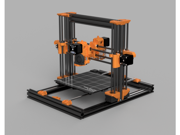
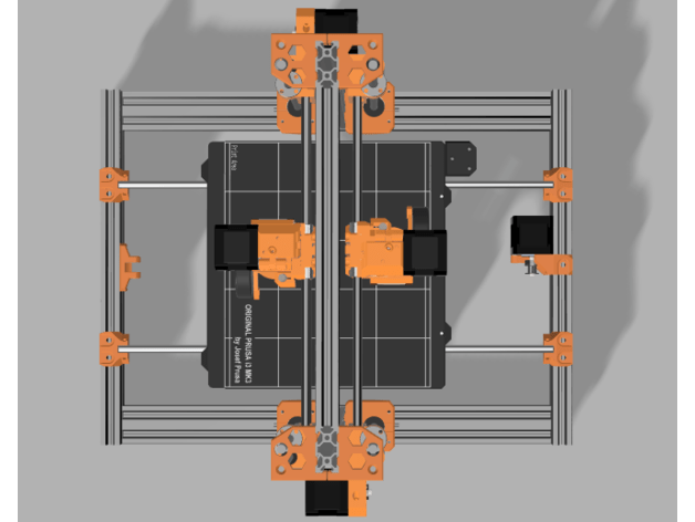
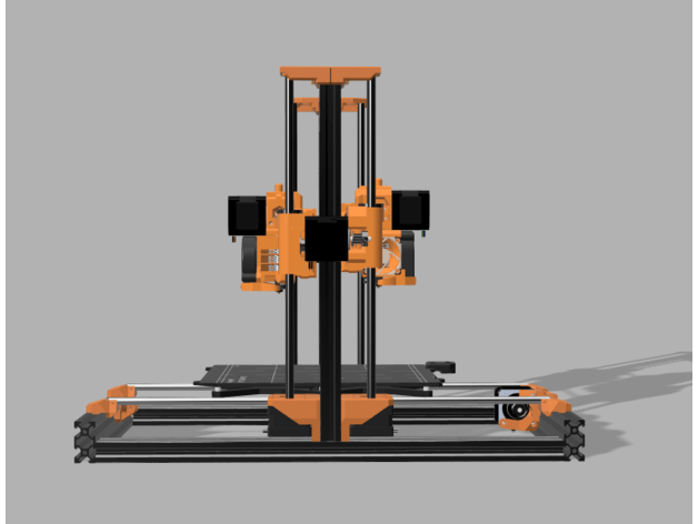
For my IDEX setup I will to use a standard Bear frame, made from 2040 aluminium, and all axes are based on standard I3 dual rods. Then, add a frond and a rear X-axis to the frame with each having its own Z-drives. Then, it looks like this:

The only additional printed parts needed are the X-axis motor holder for the rear and 2 top Z-holders:

The rest is all standard I3bear stuff.

For this printer I need a motherboard with 7 drivers, being 2*X, 1*Y, 2*Z and 2*E.

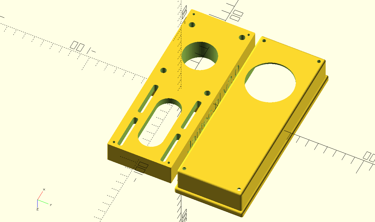
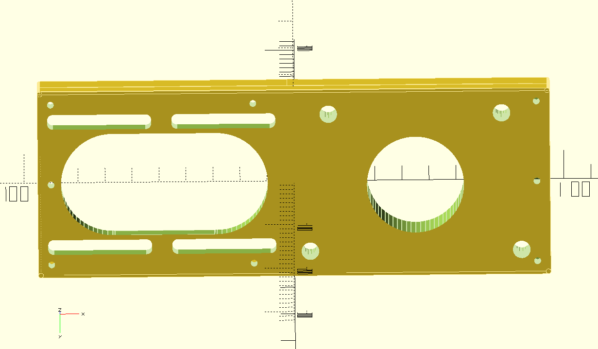
Since I have a Fly407 MB  with 9! driver positions in stock, already programmed for RRF3, wifi and with an LCD unit attached, I will use this to get a Duet setup with Duet Web Controller along.  easy to reprogram, and I can finally check the board’s capabilities.

I just need to get me a casing for the board, but that’ll not prevent me from using it!

Printing at maximum width on my Geeetech A30M with PETG and the Duet2wifi board

Yesterday I exchanged the dual nozzle printerhead (Chimera) that I have been using for dual printing all kinds of goodies like my name tag and several dual color prints, with the original single nozzle-dual extruder head.

I needed to print a LED lights circular holder that is 328mm wide, and the setrup with the Chimera just does net get that wide on the X-axis.

The result is below: It took some tweaking in the bed size settings but I have exactly 330×330 X*Y available, awesome!


Building a Prusa mini clone (Fysetc parts)

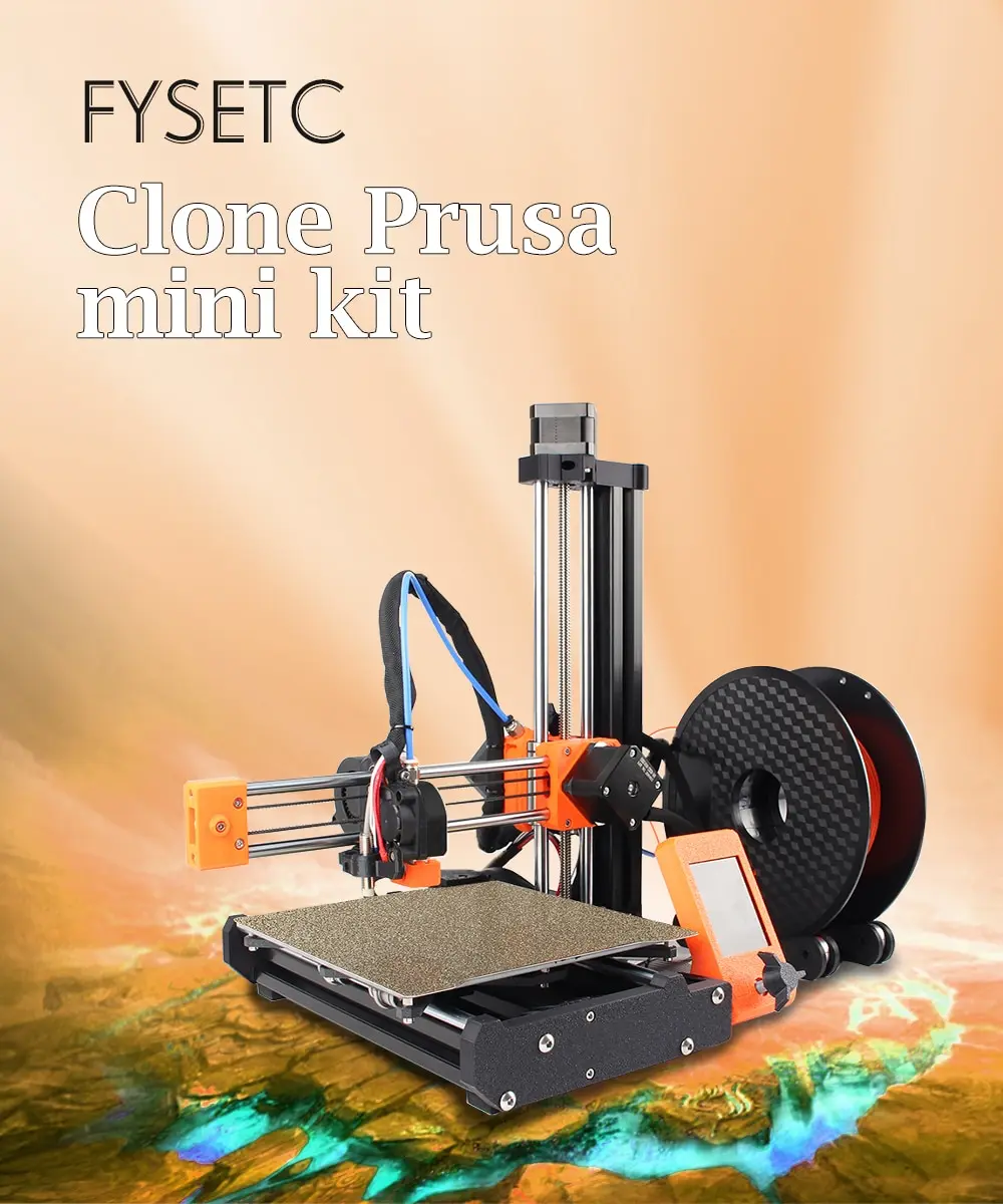
Last week (2021-Nov-04)  I ordered me a Prusa mini clone from Aliexpress.

I already have an original Prusa Mini from the moment it was offered by Prusa.  I waited for over 1/2 a year to get it delivered as I was one of the (almost) first to order it.  And-  I value the machine very positive.

I use it for professional prints, mostly with white, orange and black PETG.

I hope that my additional Prusa Mini will be just as perfect as my original one.

On Ali, everything was offered except the printed parts.  It includes a buddyboard 32 bits with 2209 drivers, LCD 2.6 inch, 3 motors, nuts and bolts, cables, hoses, bearings, clamps, hotbed, pei sheet, rods, extruder, fans, extrusion, you name it, really everything is included for 105 Euro’s .  But- you guessed it- I never got anything delivered. I have a dispute running now, hopefully I wiull get the money back.  And- I ordered a new one, now the costs are more than double, as is to be expected.

As add-on I ordered 2 renewed Z-sensors (including temp sensor)  from Prusa for Eur 50 incl. Tax and shipment.  With this, both mini’s can be upgraded to Mini+ 3d printers.  Except the longer bed of course.  Also, both the buddyboards will get the Mini+ firmware.

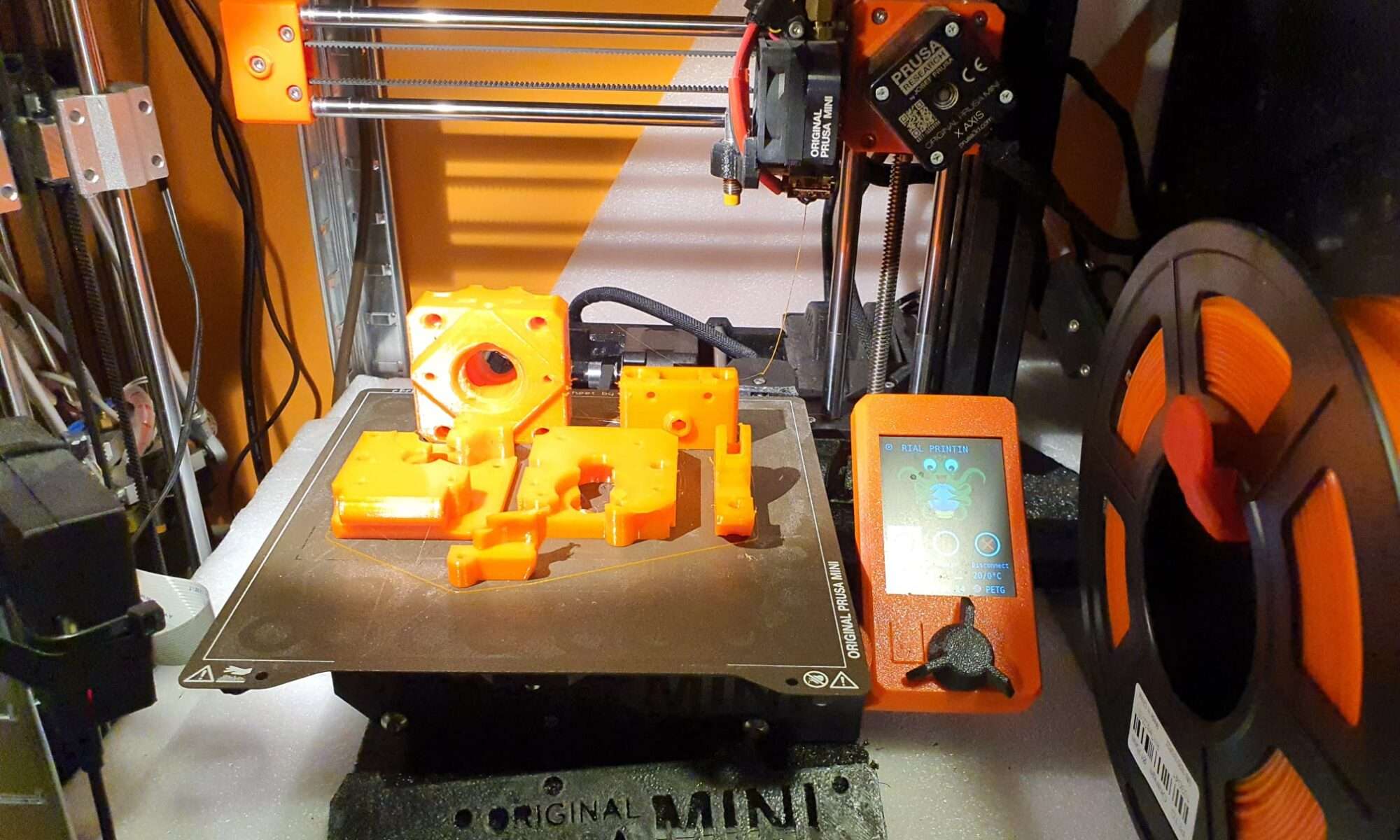
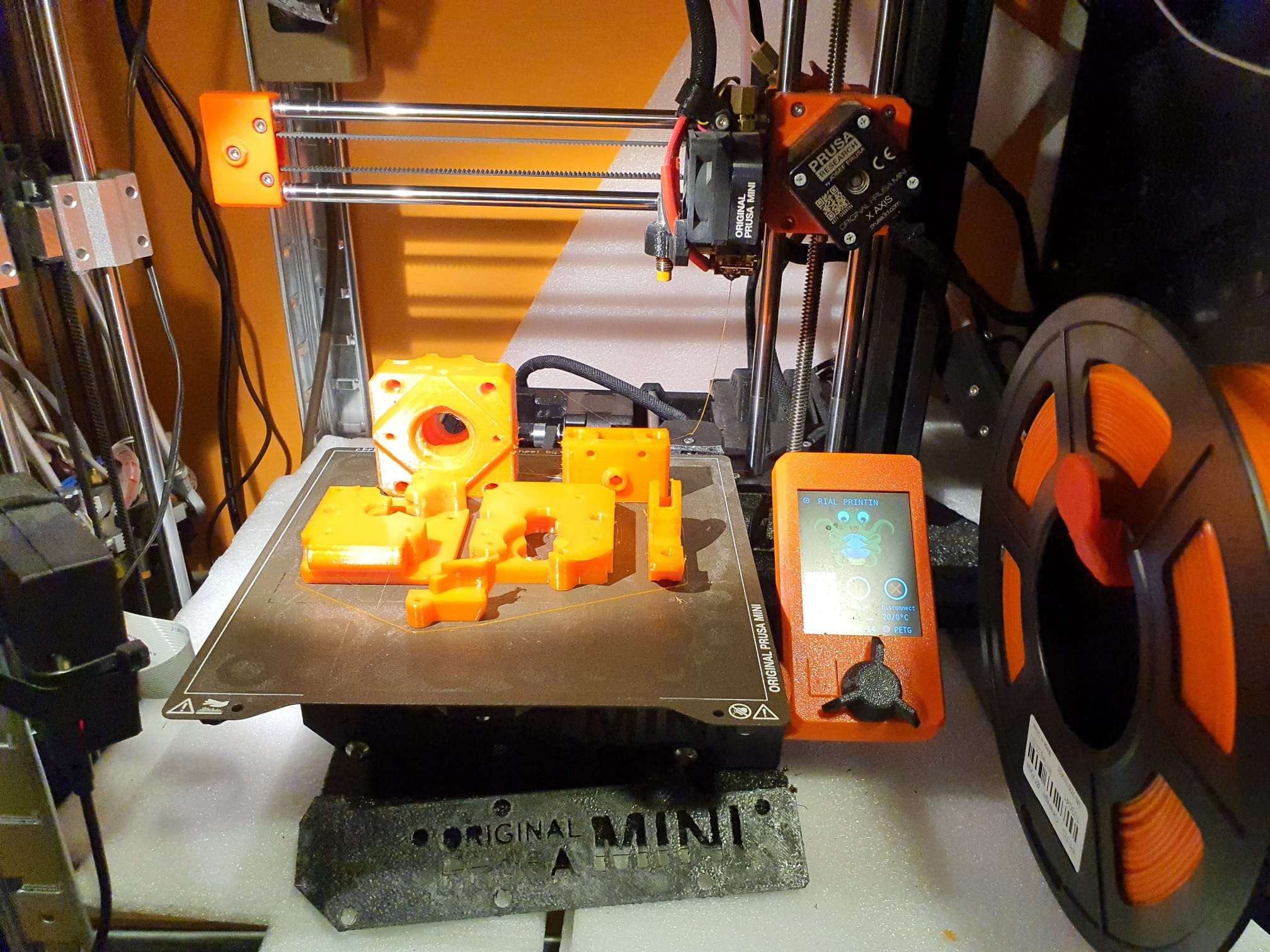
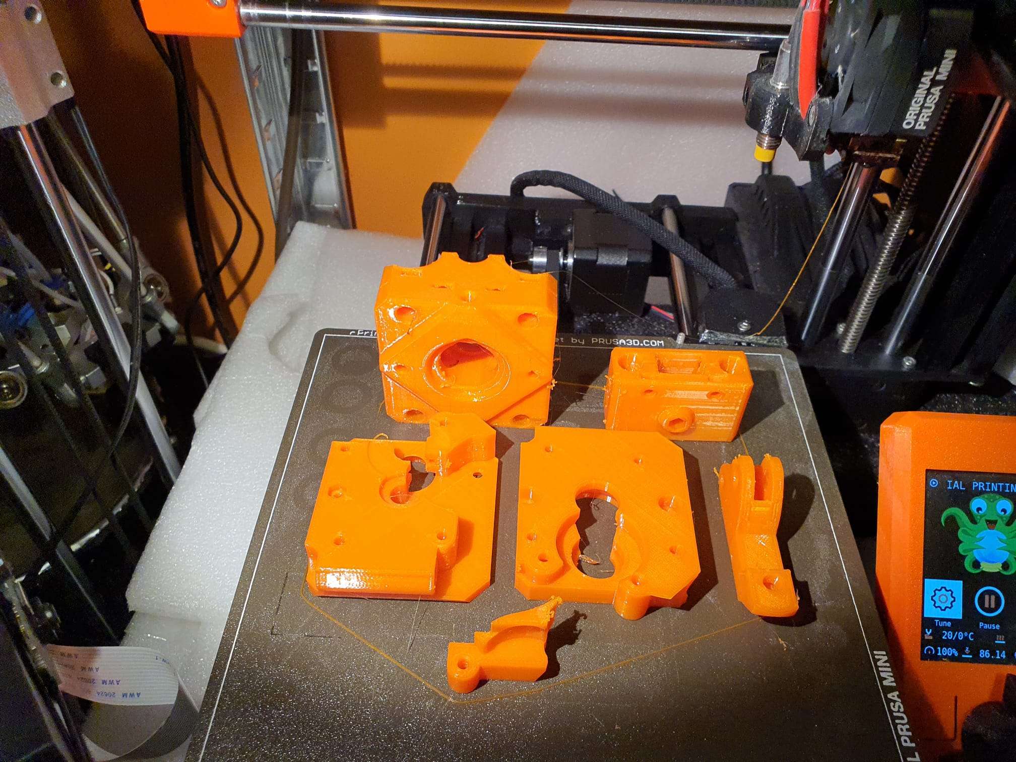
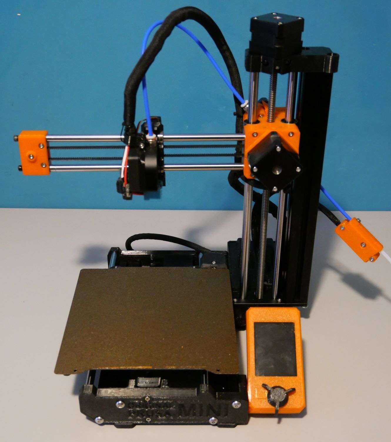
Since I also own an original Prusa mini, printing the parts was easy, as you can see in the attached pictures.:

Still, also a Prusa mini can have stringing wth PetG. OR, i think this was caused because I purposely set the temp very high to get extremely solid prints.  Whatever, I cleaned the printed parts afterwards with a knife and that turned out to be easy enough.

The black PETG parts got printed on my Ender 3 pro+.

Built after receival of the non-printed parts on 2021-12-22  JMWG.NL

I upgraded the Buddyboard V1.0.0 straight away to the latest Prusa Mini firmware and compared the prints against my Original Prusa Mini.

I honestly could not see any difference between the two of them.

The stuff I ordered on Ali:

Https://github.com/FYSETC/FYSETC-Prusa-mini-clone

3.2/2.8 MW power is momenteel in voldoende voorraad, bent u welkom om een bestelling plaatst, de voorraad is in de Spaanse magazijn, dank u voor uw steun,

Video tutorial:


Pakket:
Schroef kit 1
Tool kit 1
USB disk 1
Gladde staven kit 1
3030 extrusie kit 1
625 lager 3
12.5mm, 3mm OD as 1
4.9*12mm as 1
16T GT2 Katrol (als MK3) 2
Platte Katrol (als MK3) 2
X/Y riem 2
LM8UU 5
LM10LUU 2

Elektronica
Motoren kit 1
Buddy besturingskaart 1
Thermistor hotend 1
Thermistor verwarmd bed 1
Filament sensor kit 1
Heatedbed 1
Verwarmd bed kabel 1
LCD (als kiezen) 1
24V 40w cartridge 1
PSU (als kiezen) 1
Minda 1
Fans 2
Extruder versnellingen 1
Hotend kit 1
Bowden tube 1
Y vervoer 1
Z bodemplaat 1
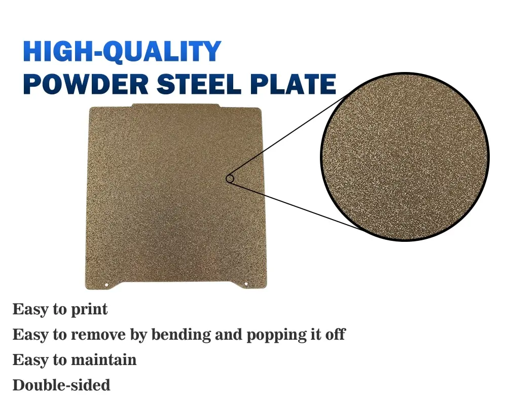
Gouden textuur stalen plaat 1

Dit product omvat niet prints. Als u of kopen het zelf, het bestand afdrukken link: https://www.thingiverse.com/thing:4338197
3.2 inch scherm case STL Link:https://www.thingiverse.com/thing:4307001

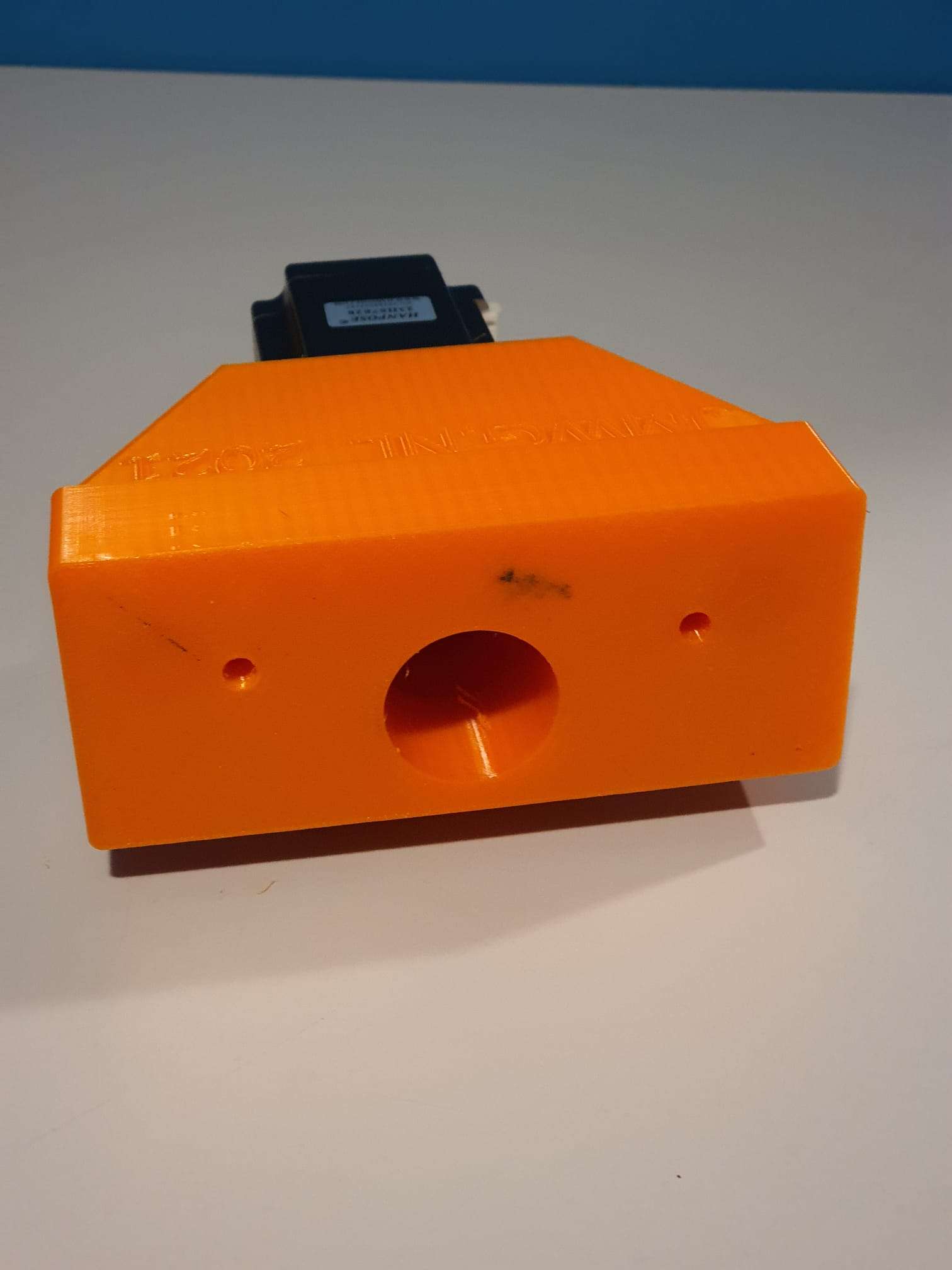
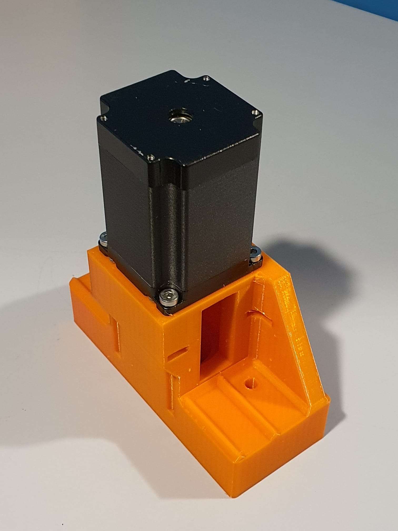
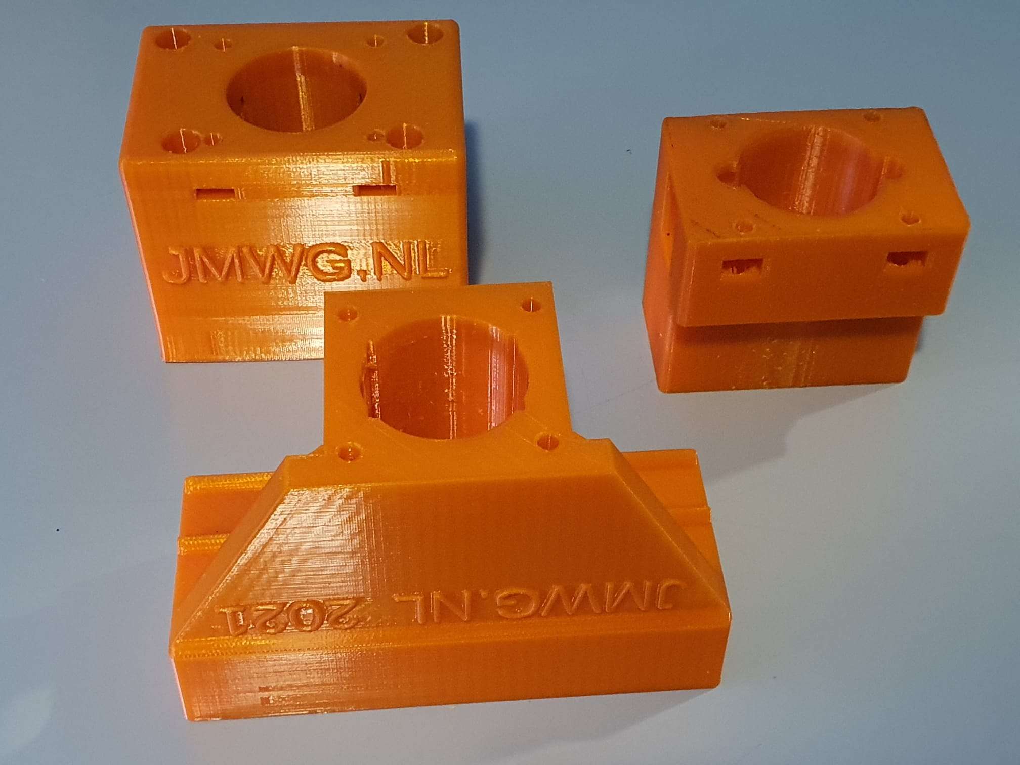
Minimill CNC conversion WMD16LV Z-axis adapter for NEMA23 direct drive

While I was making my CNC adapter plates with teethed wheels and belts, I discovered that not much exists that is ready to use for these conversions.

DOWNLOAD:

MINIMILL_BF16L CNC_Z_adapter direct drive 2022_07_25_V1_5-jantec.nl

I am therefore also making direct drive adapter parts, to try this out.

This is the third piece I make for direct drive, for the Z-axis.

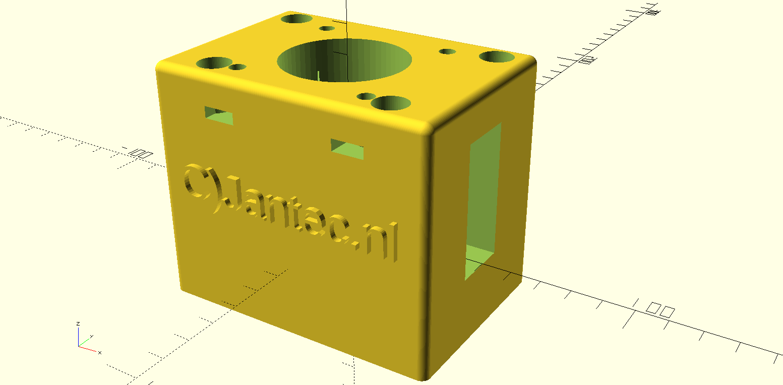
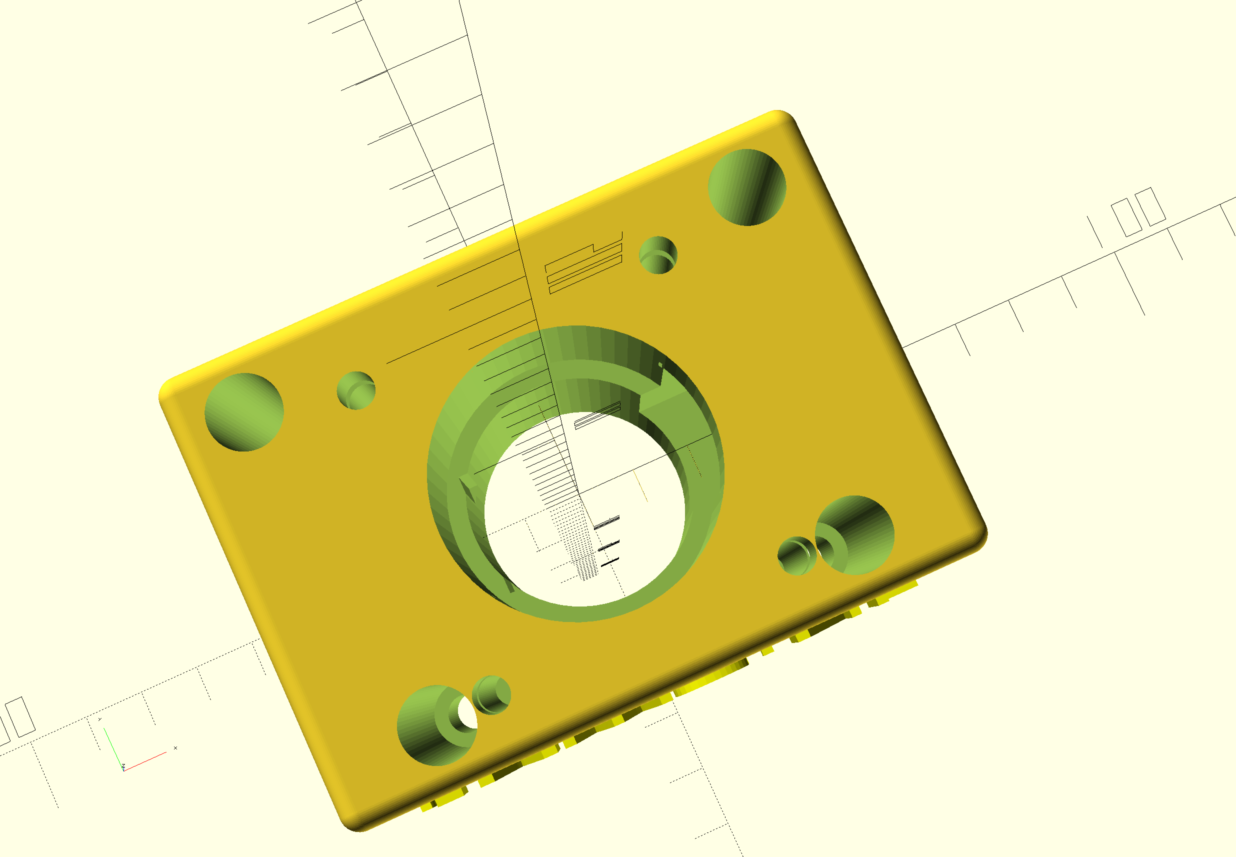
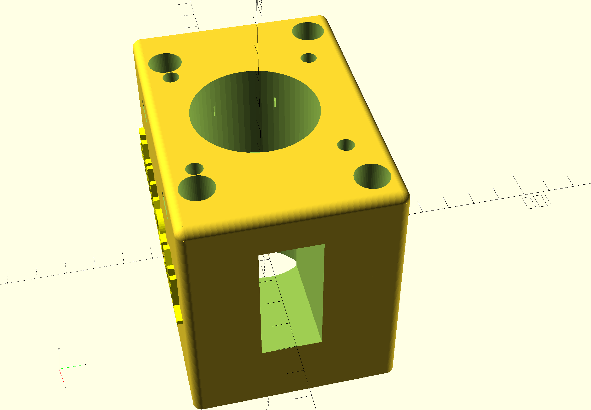
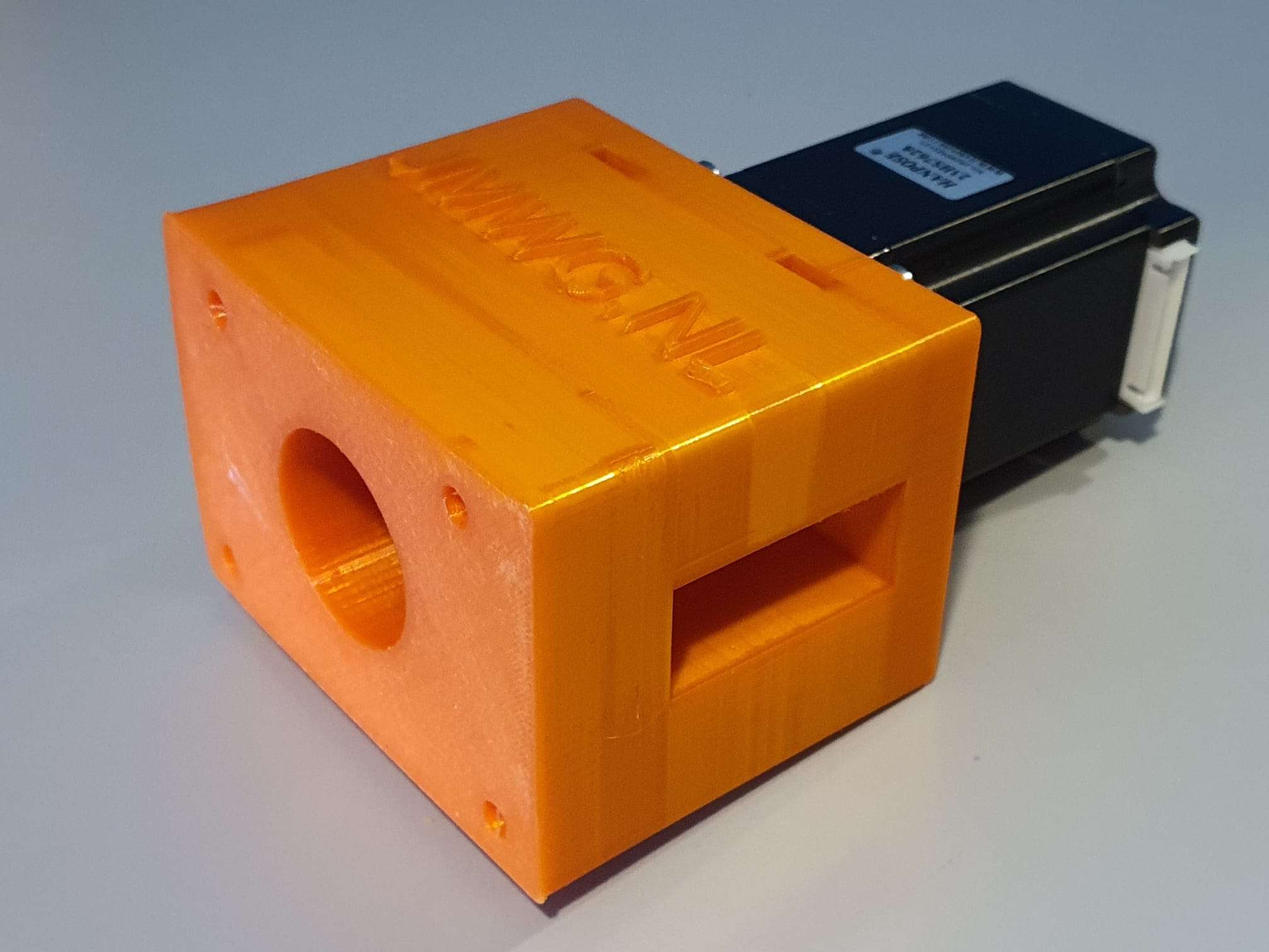
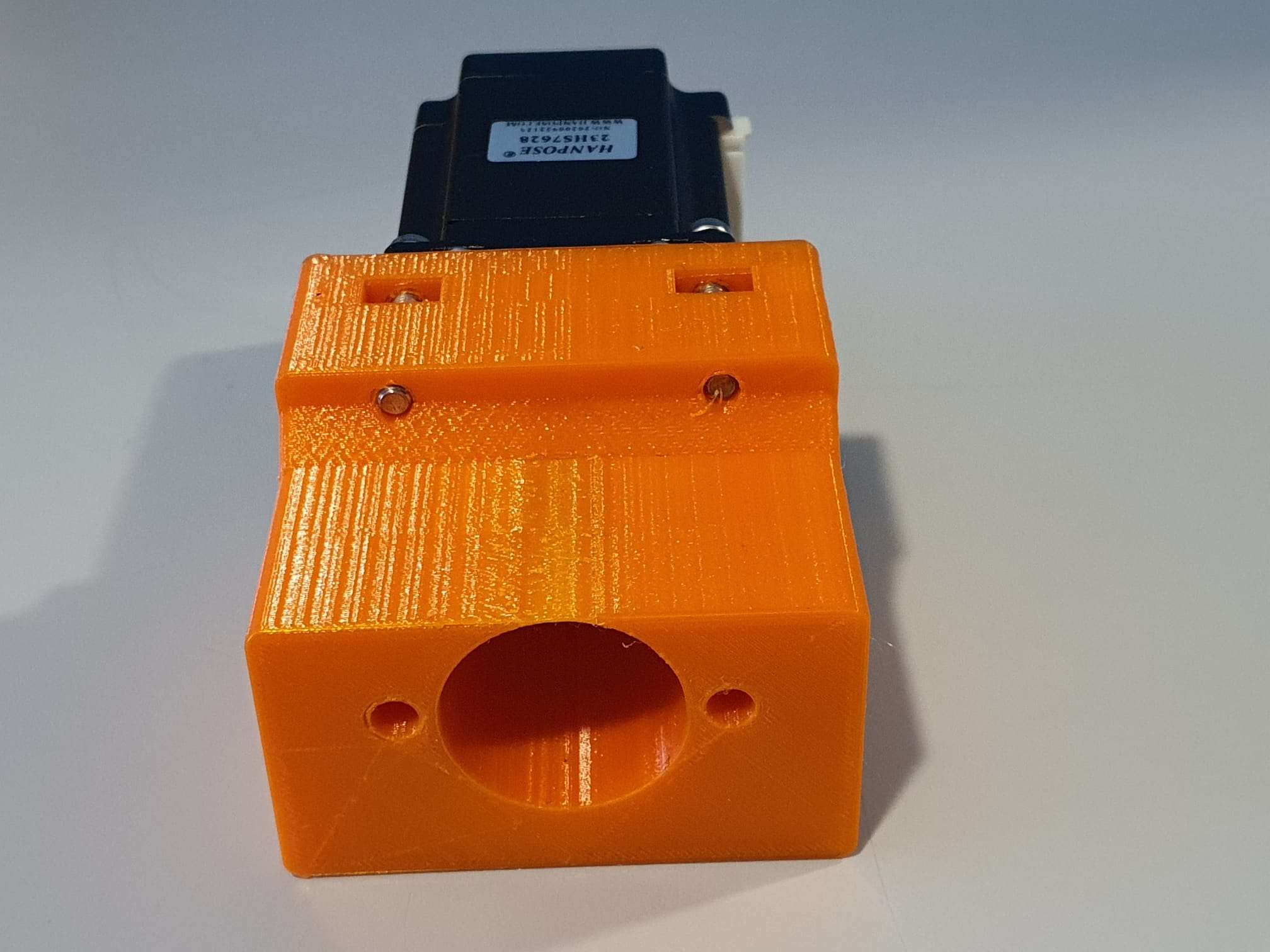
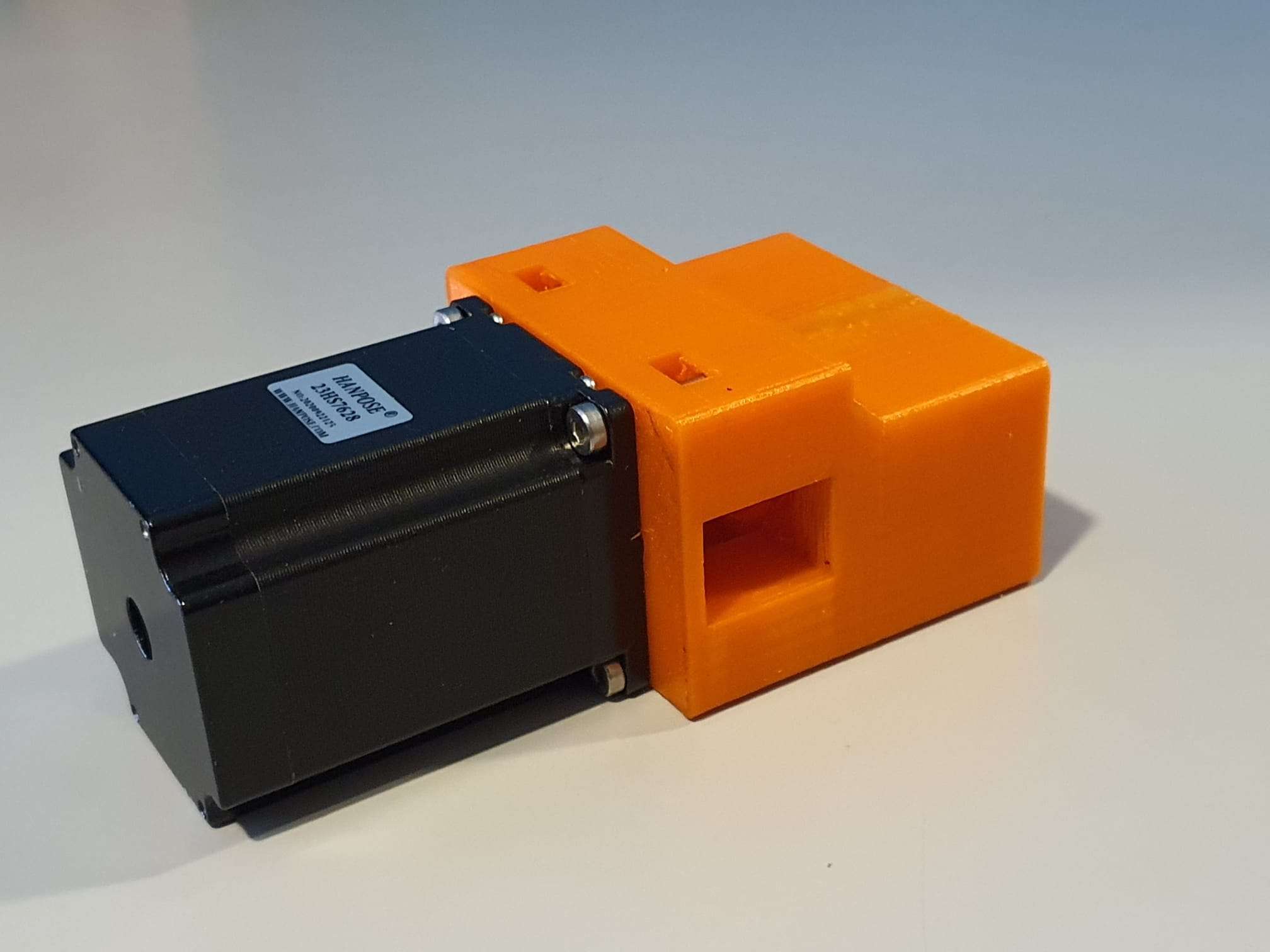
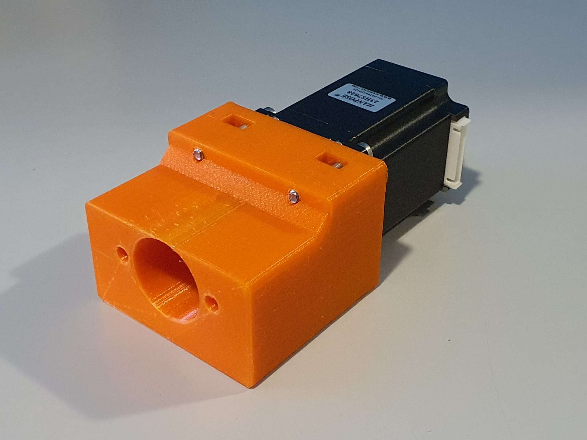
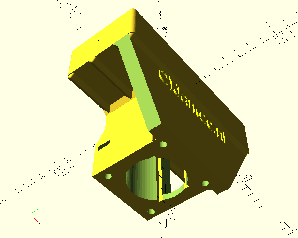
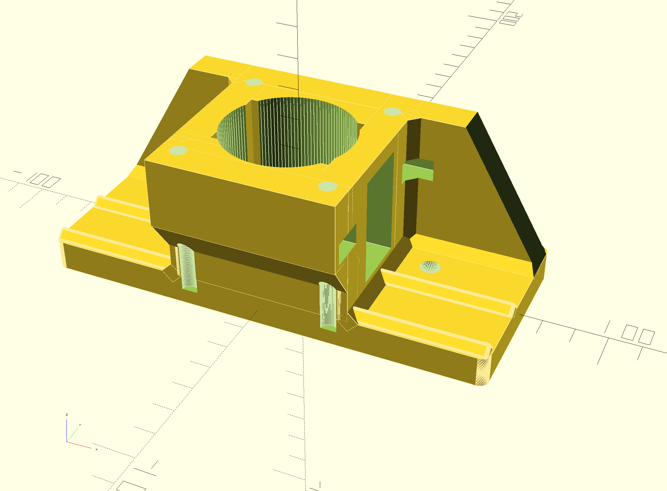
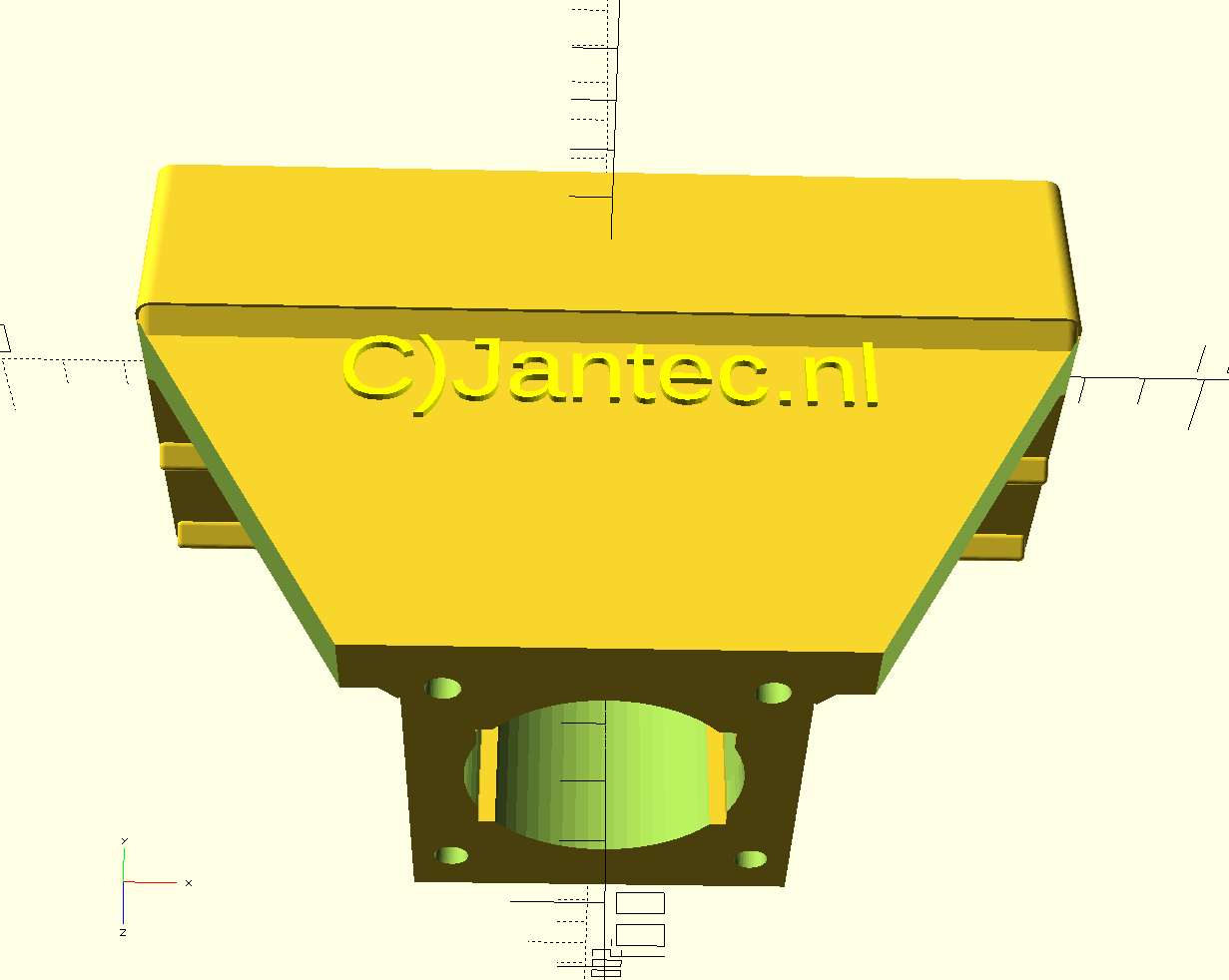
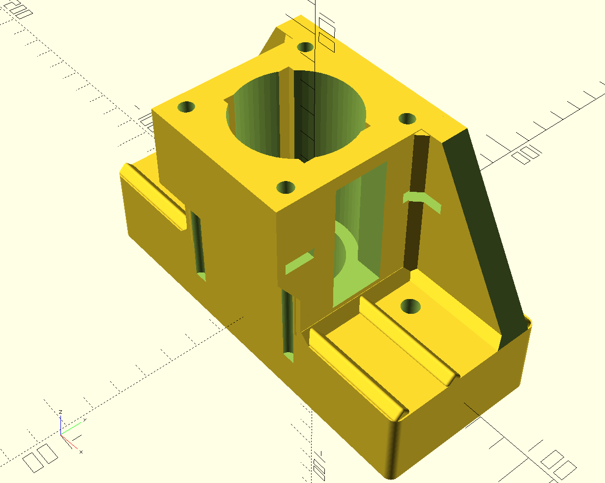
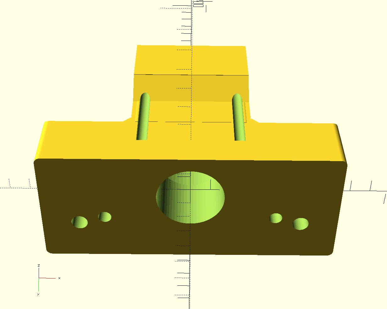
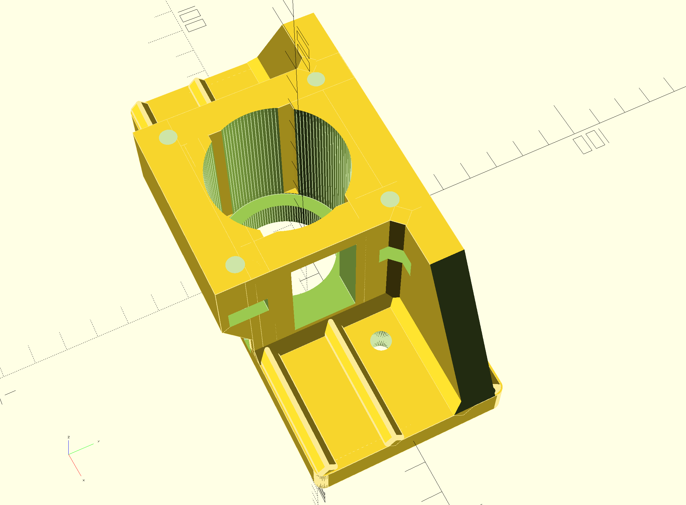
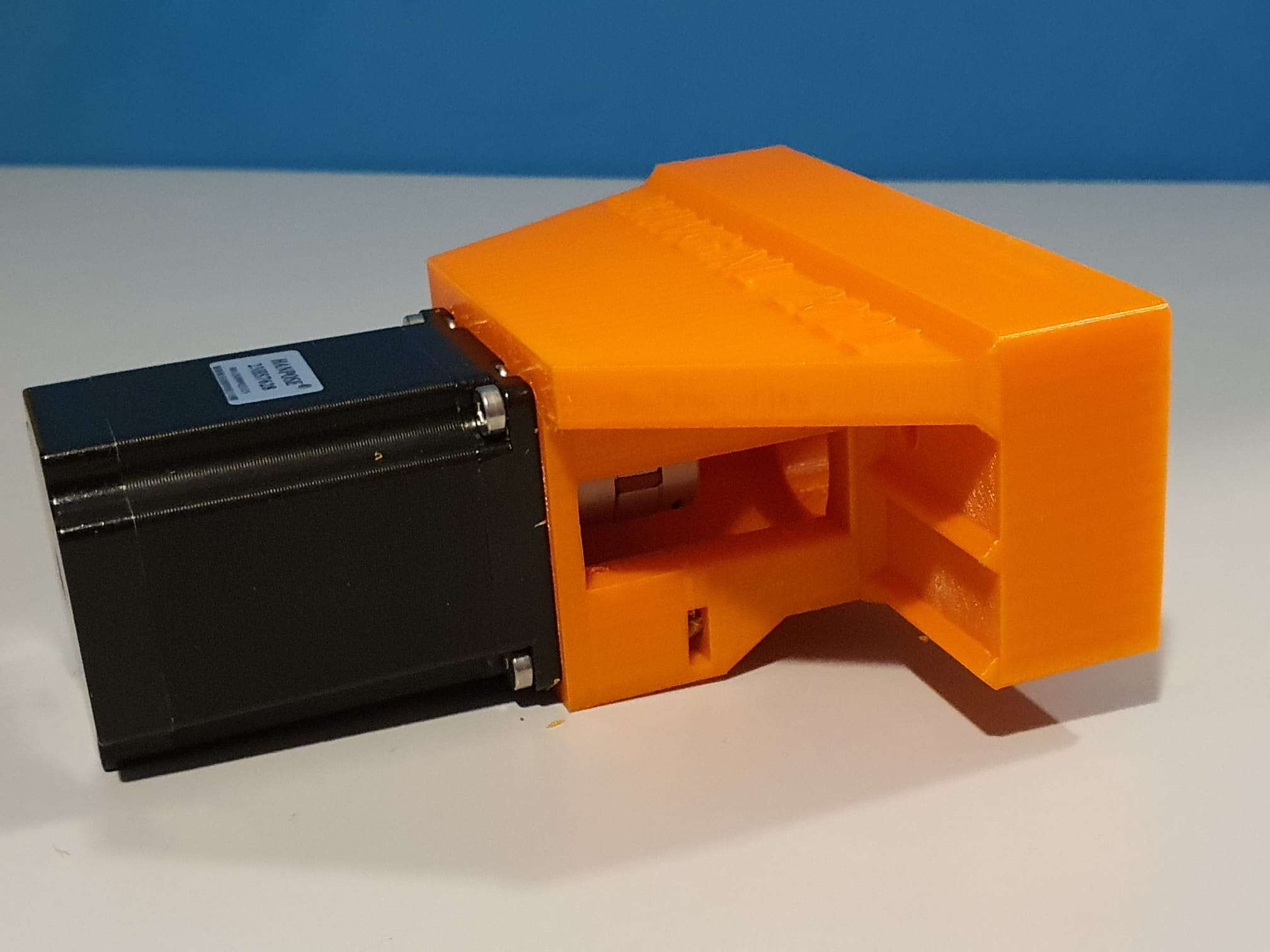
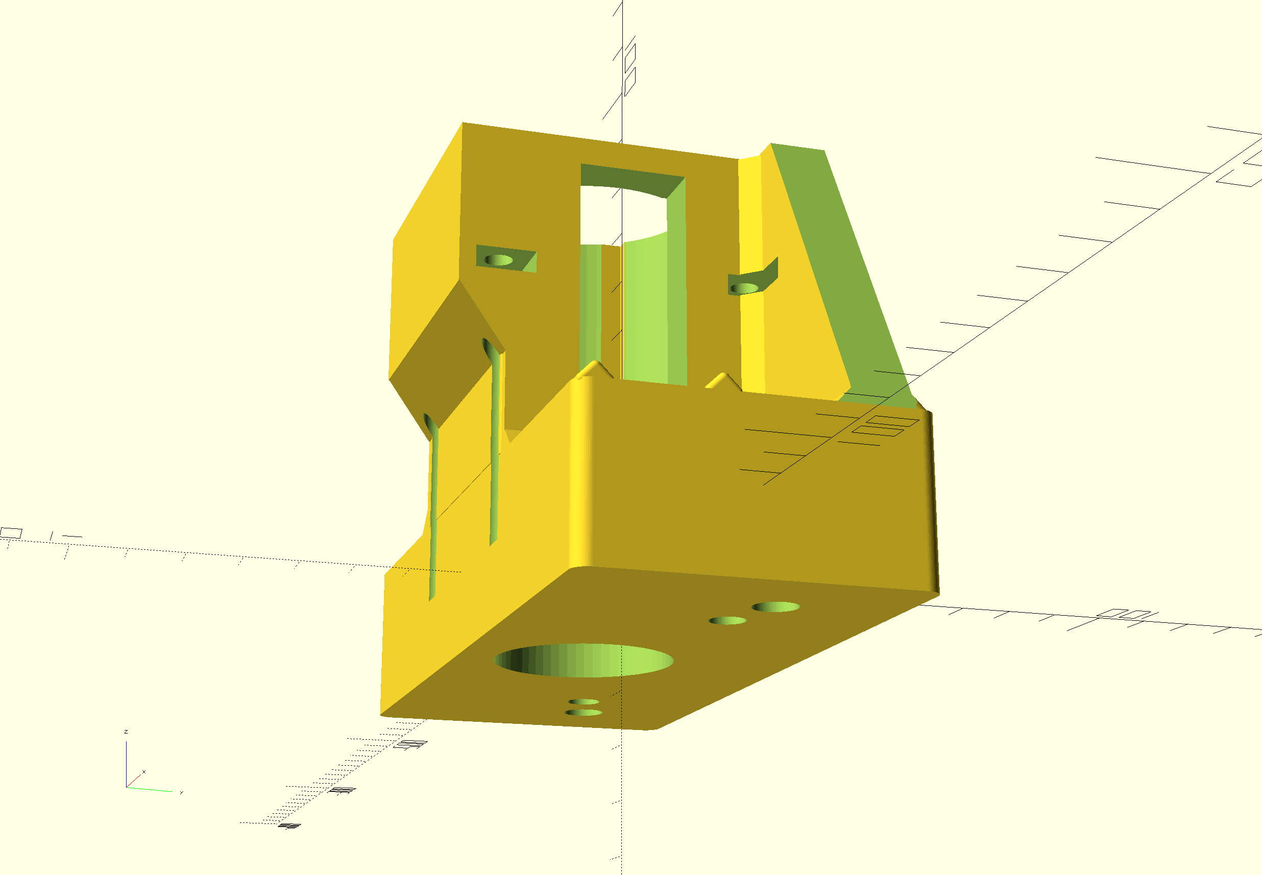
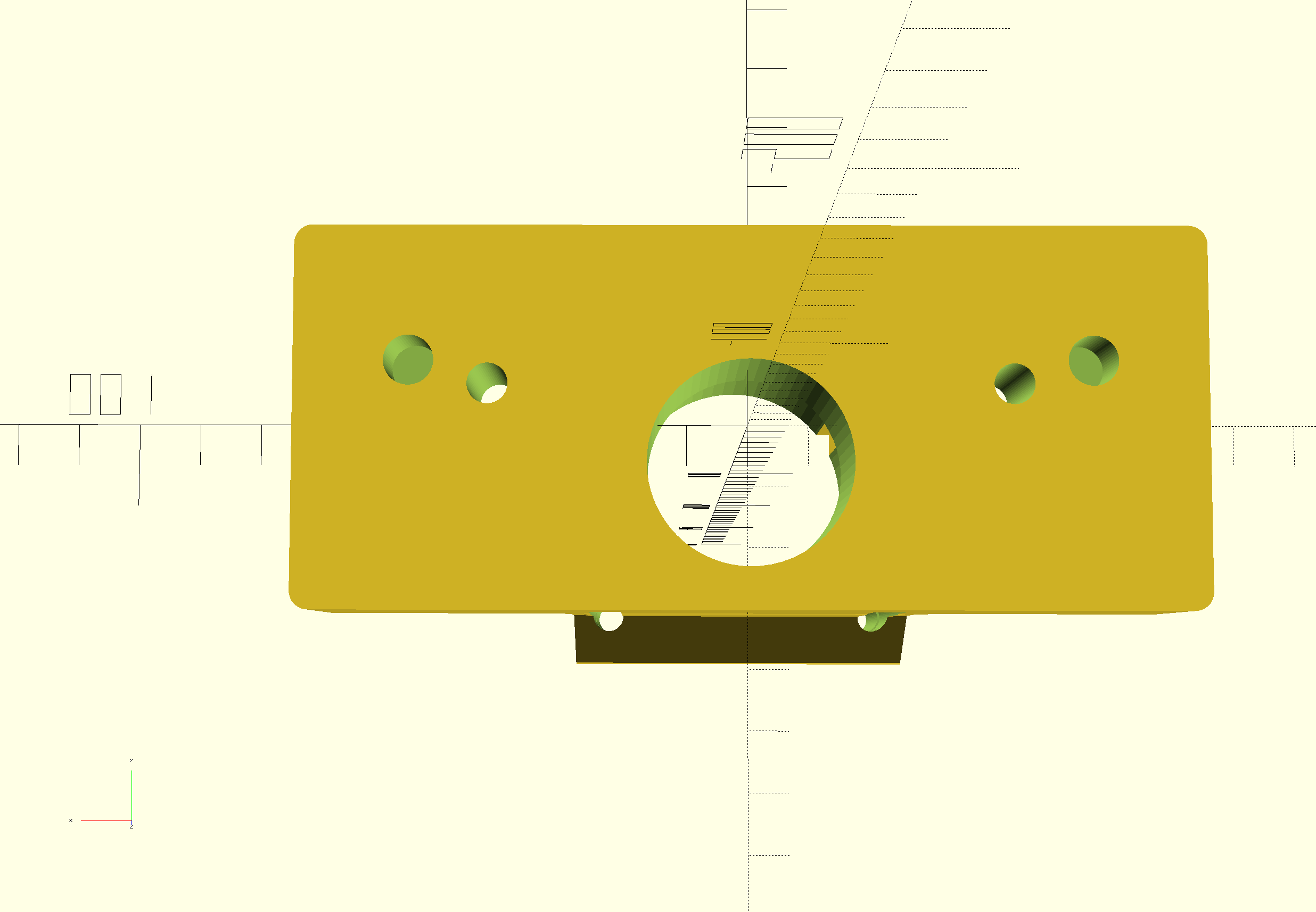
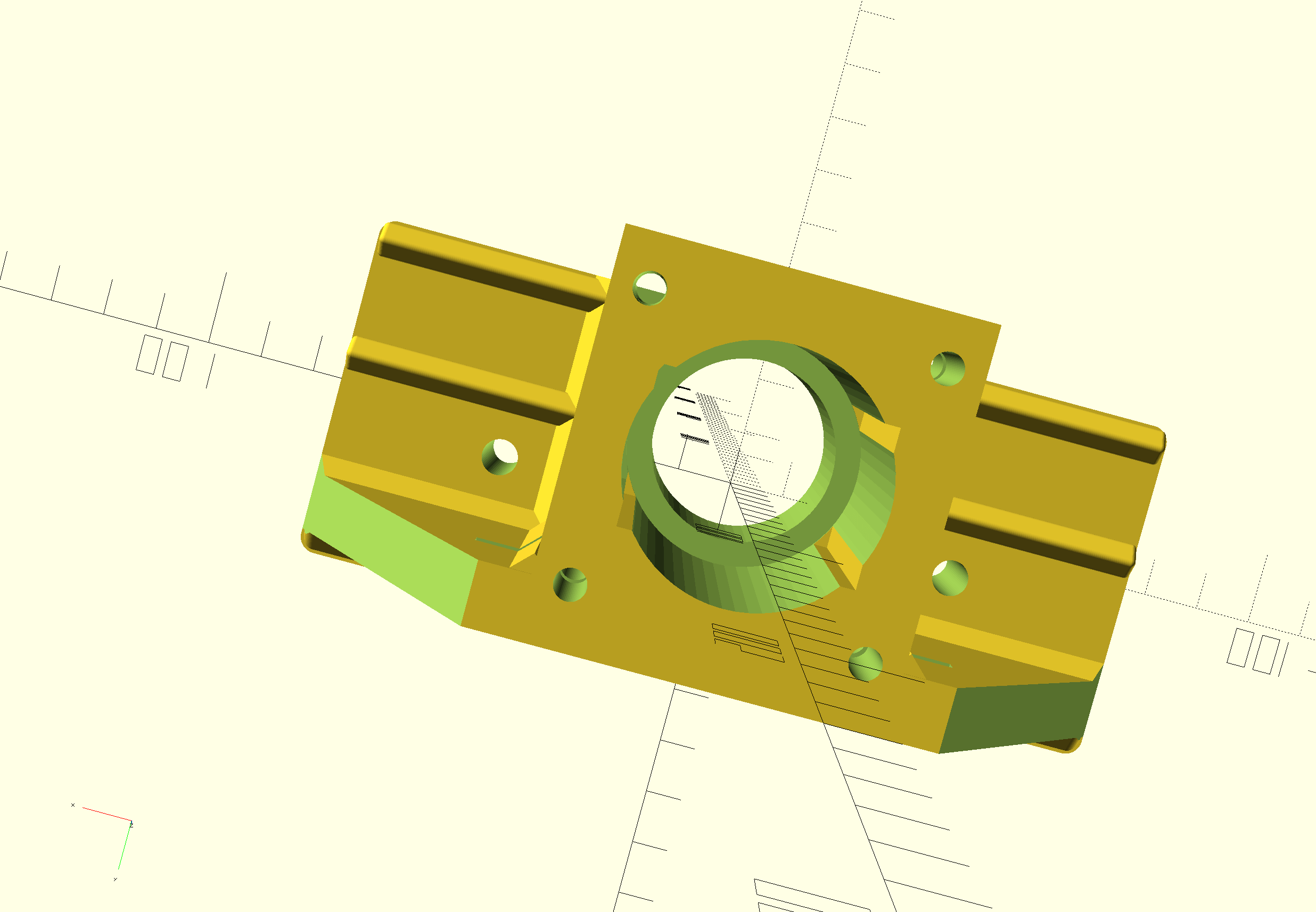
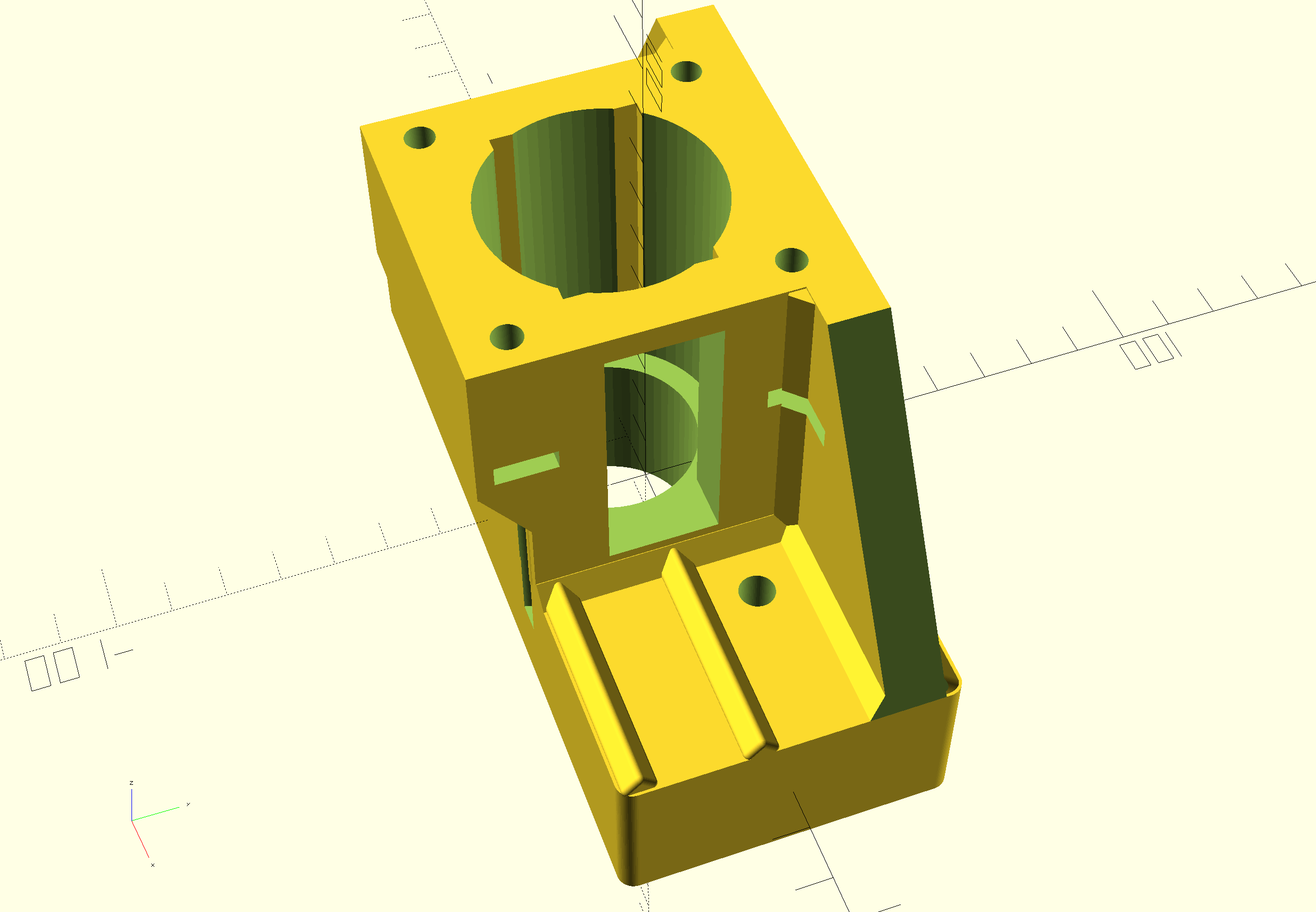
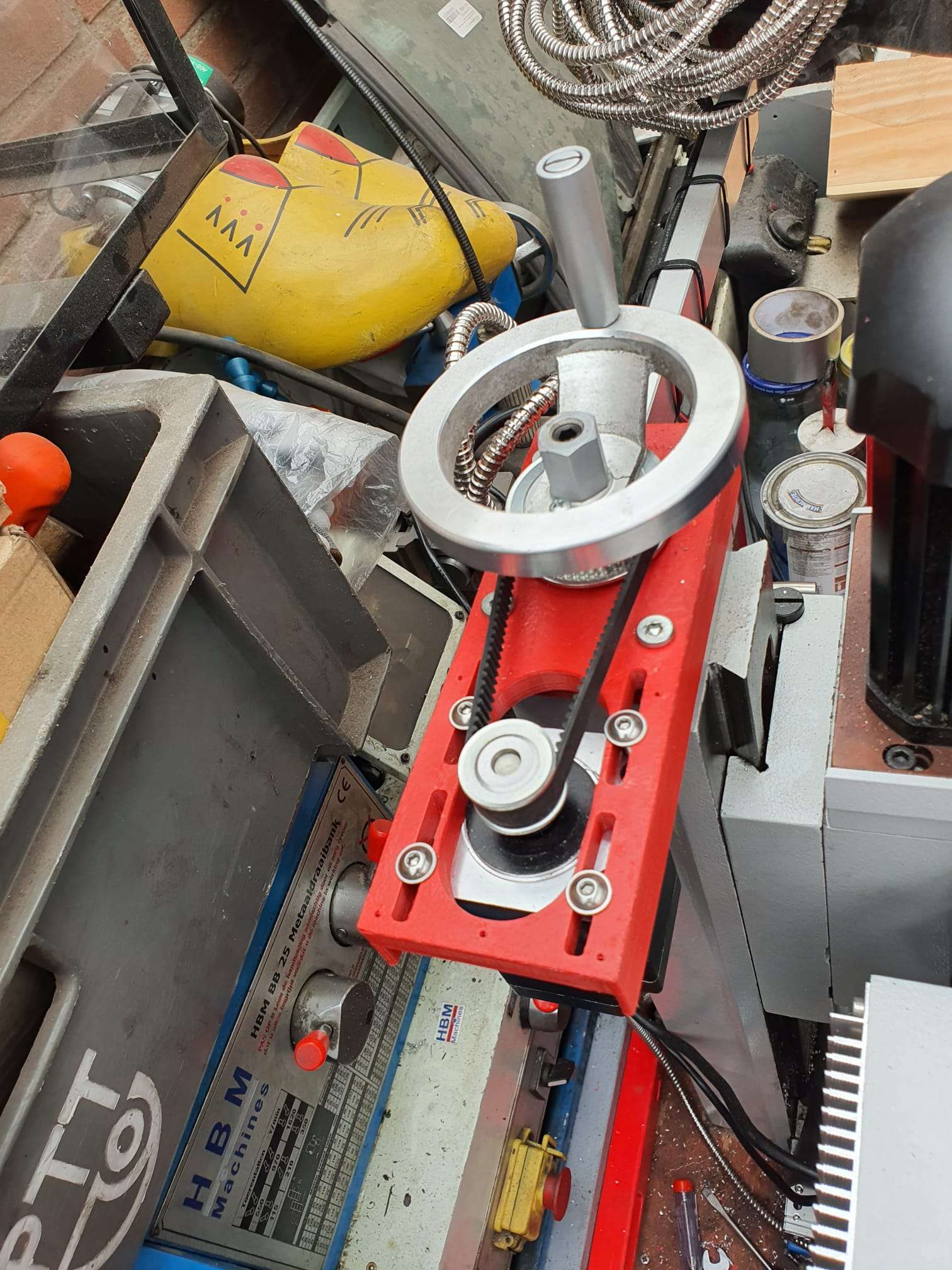
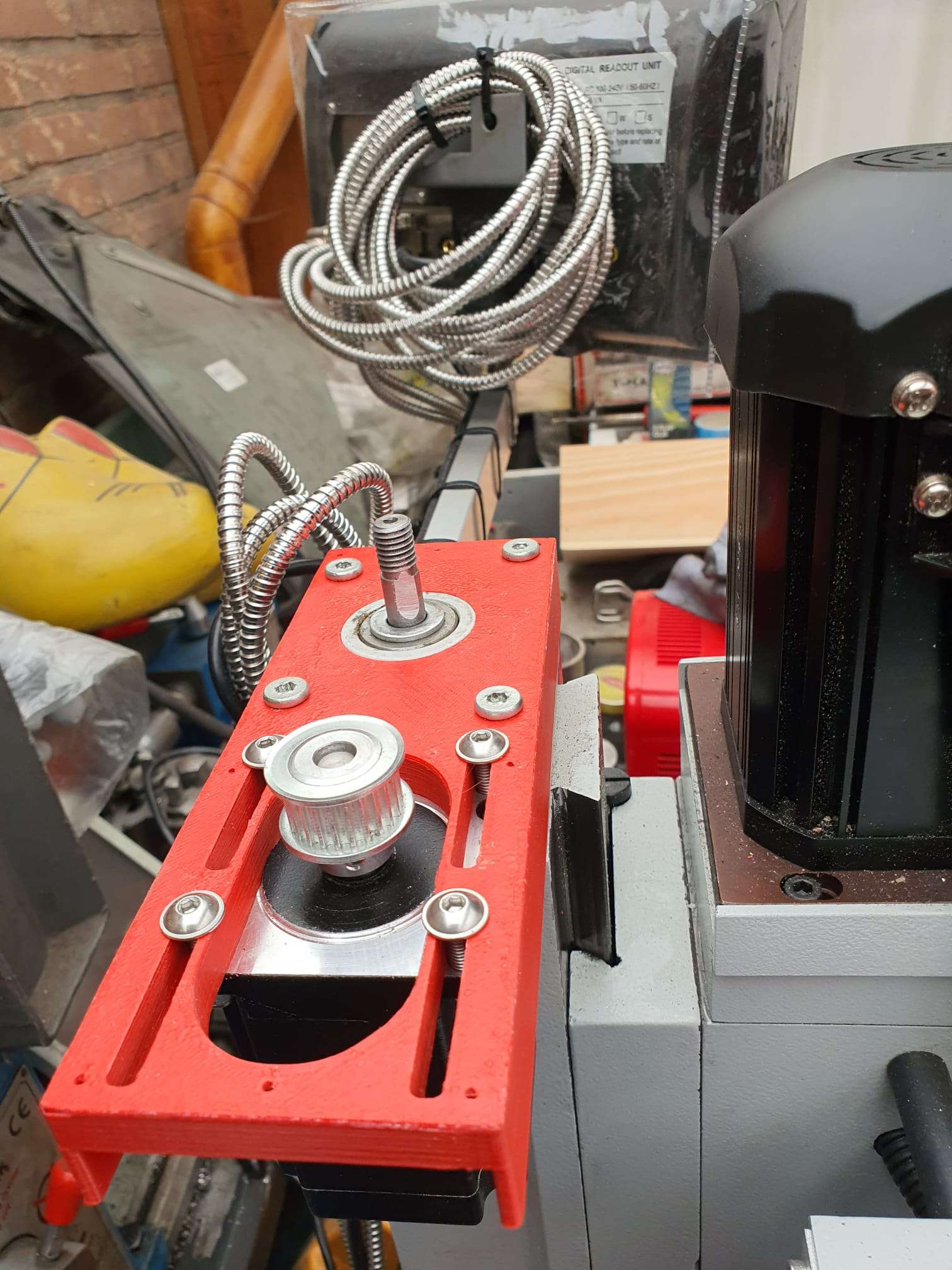
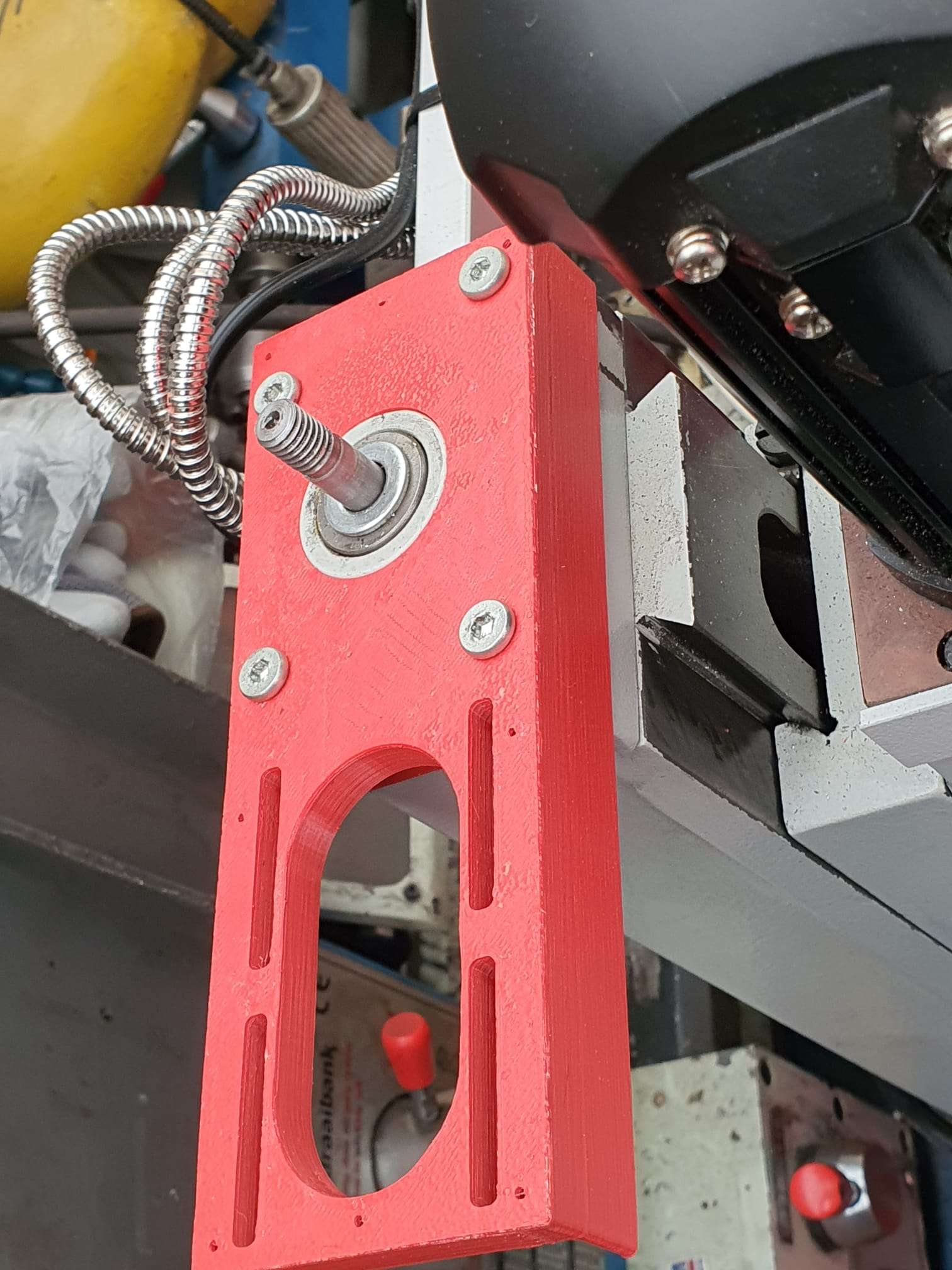
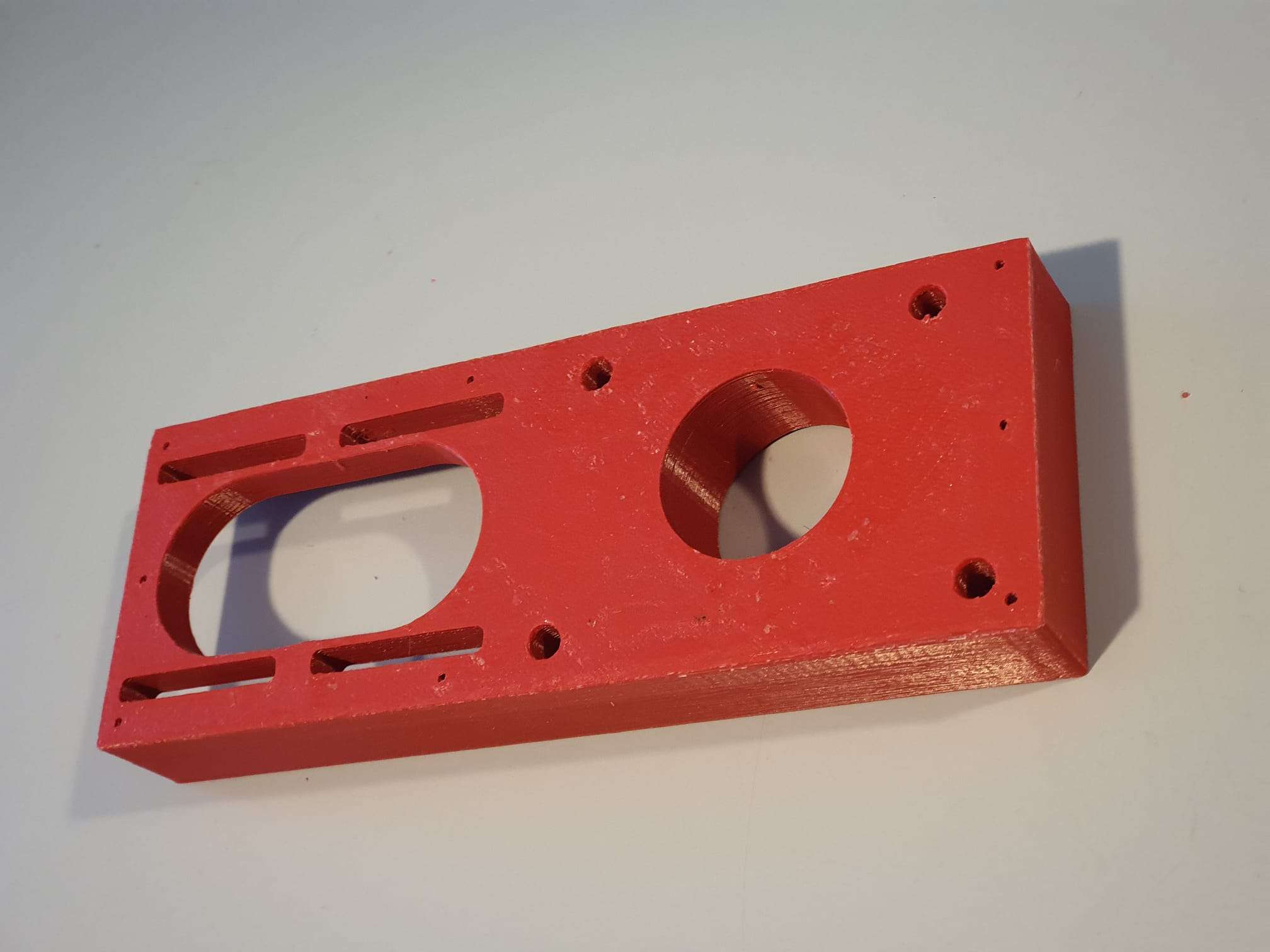
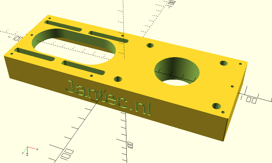
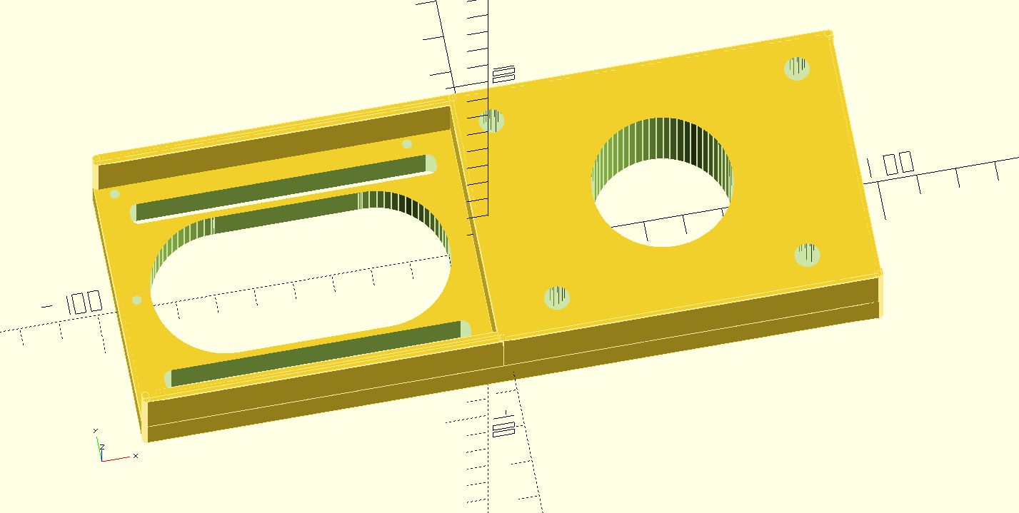
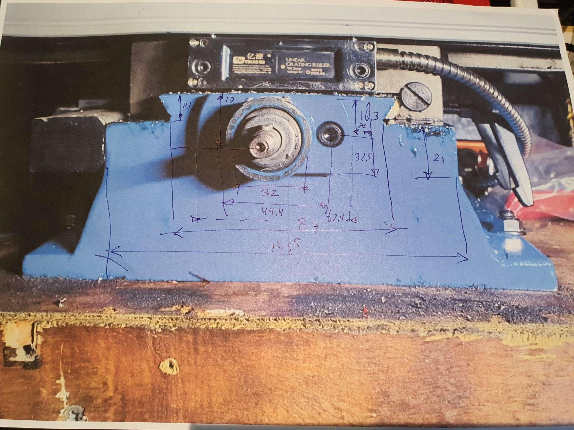
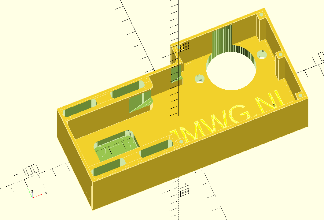
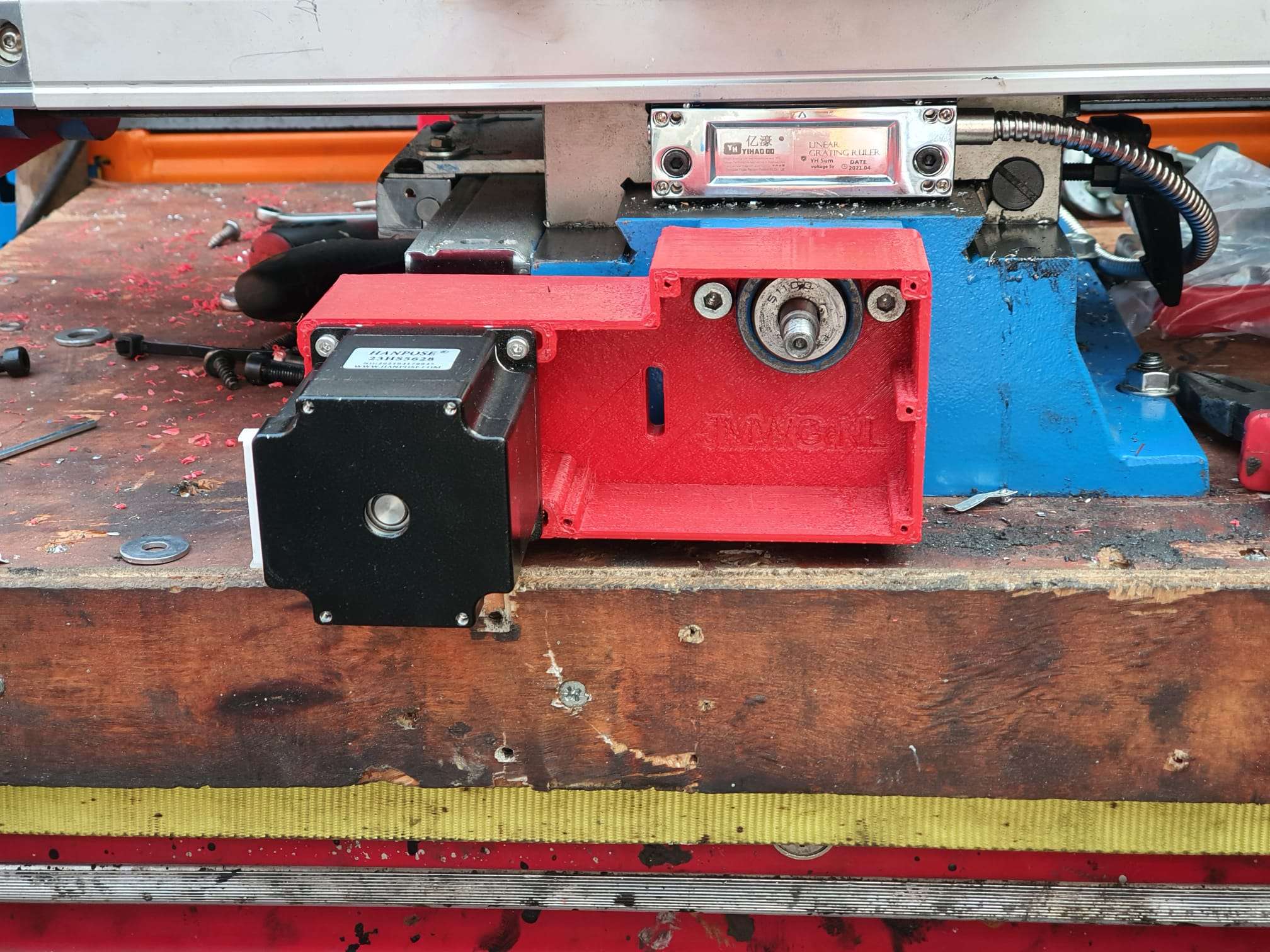
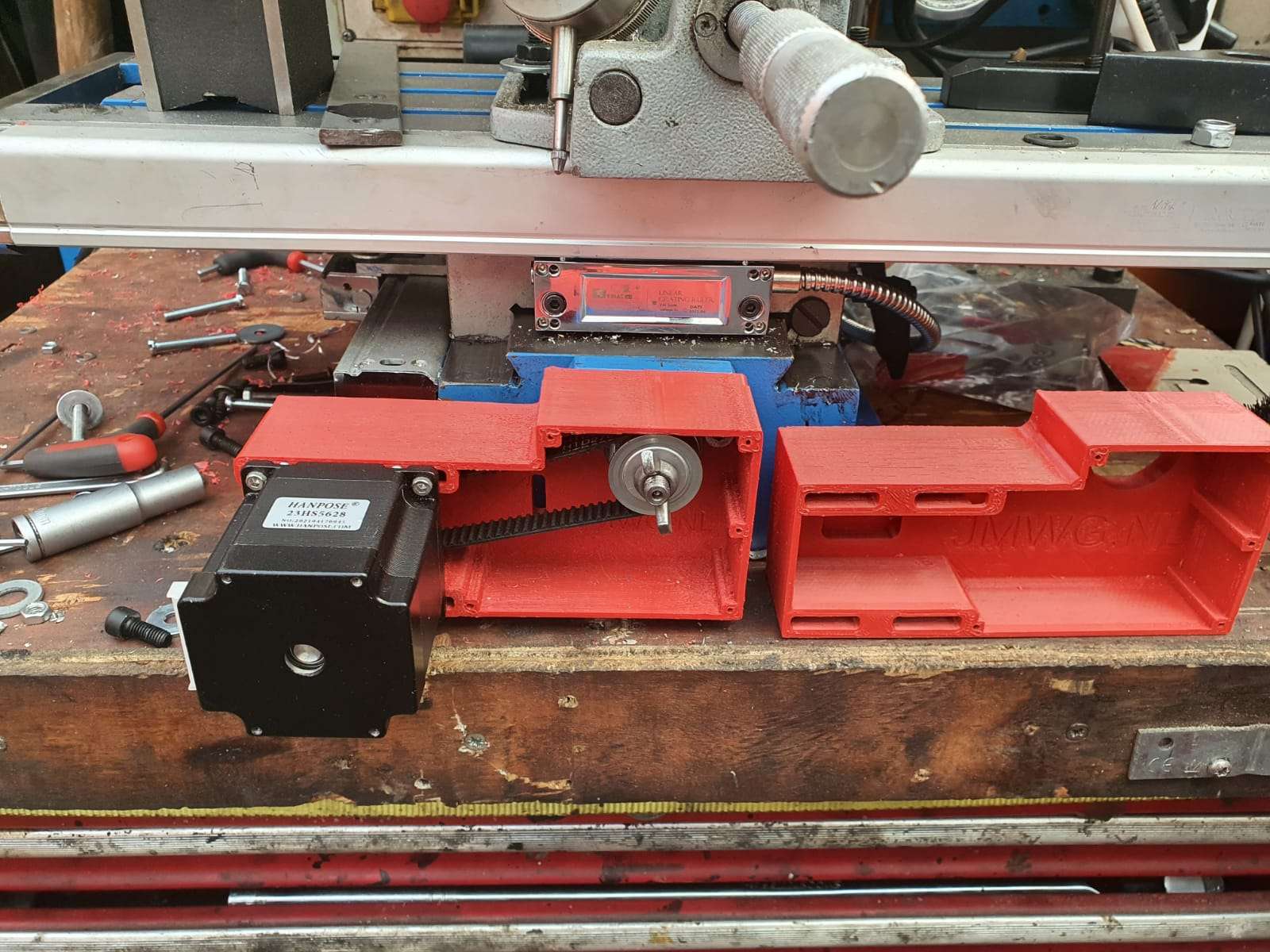
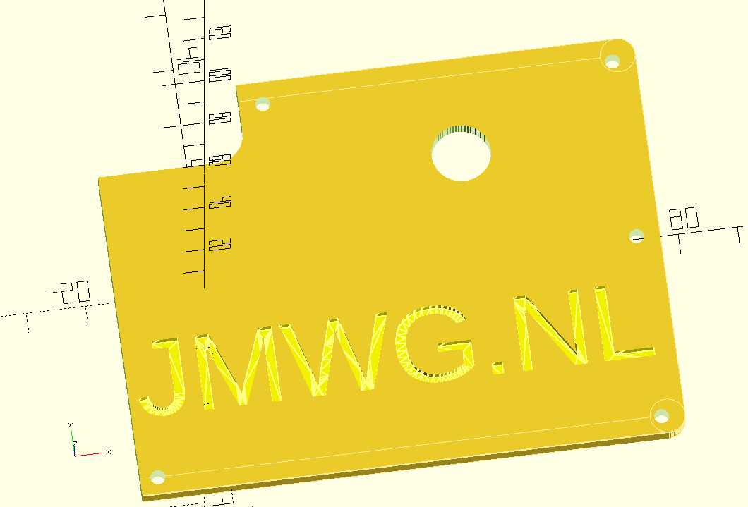
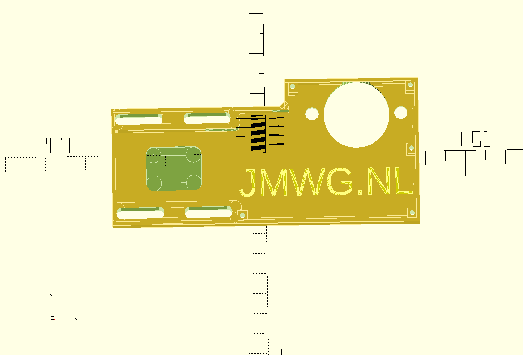
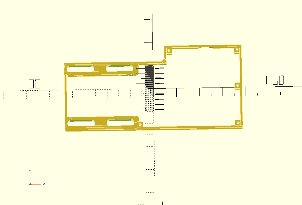
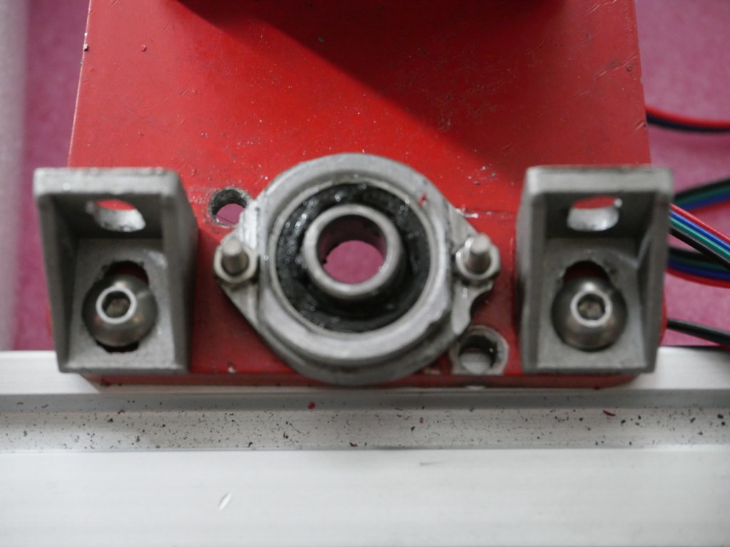
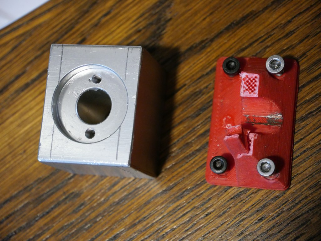
This pice is fairly simple: First a good fit is needed to mount the adapter to the top of the Z-column, and the holes for the 4 bolts need to be acactly correct.  Also, the same for the leadscrew hole of the bearing holder.

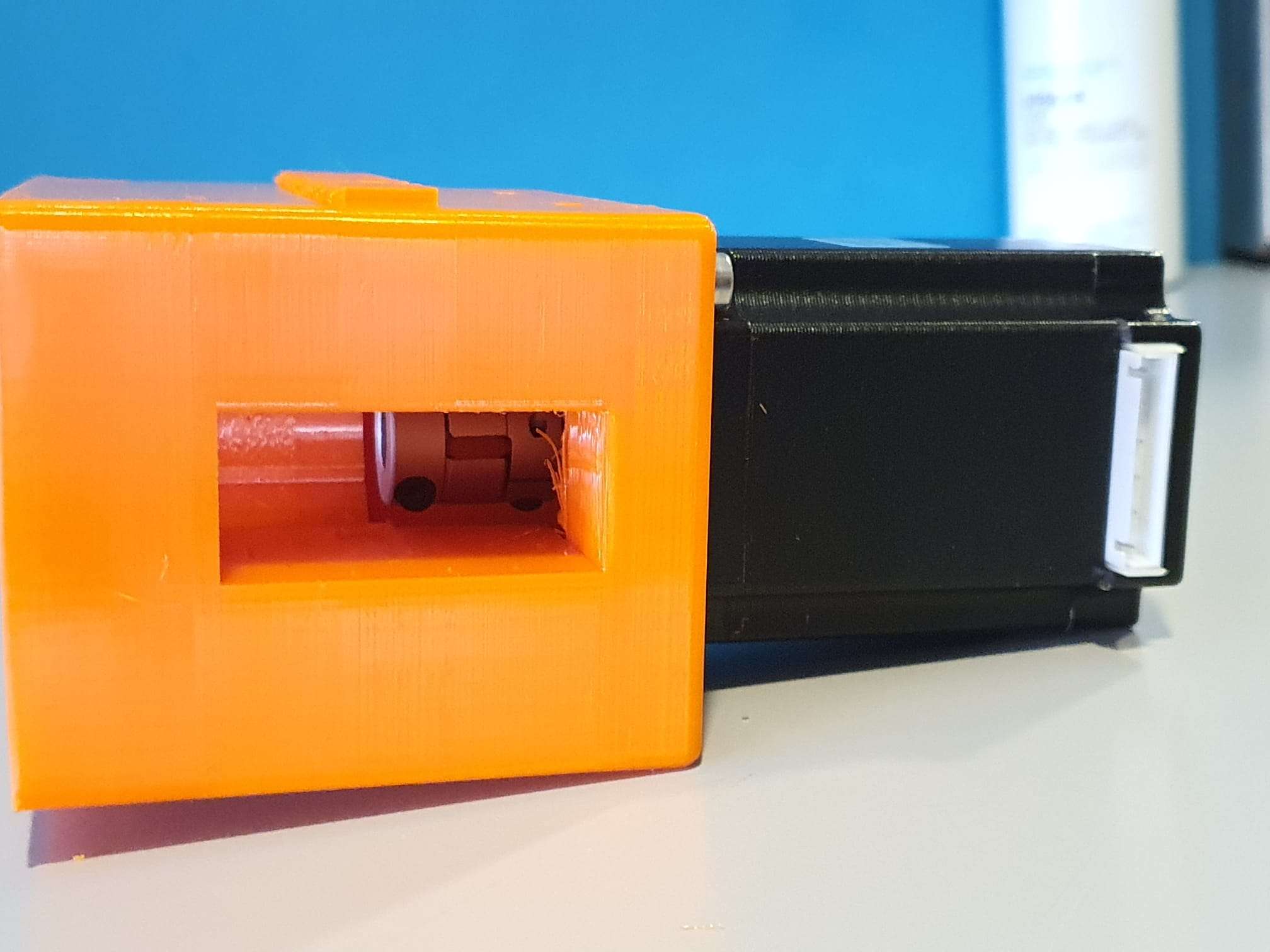
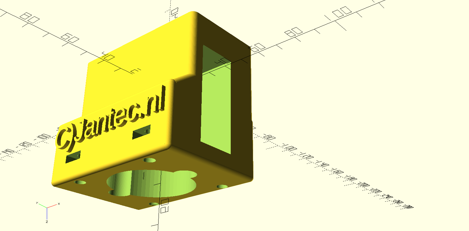
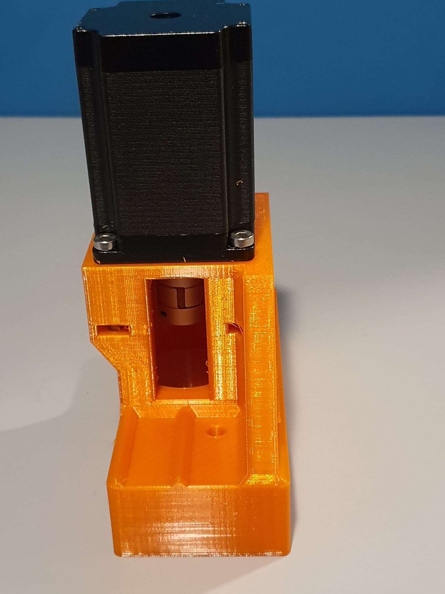
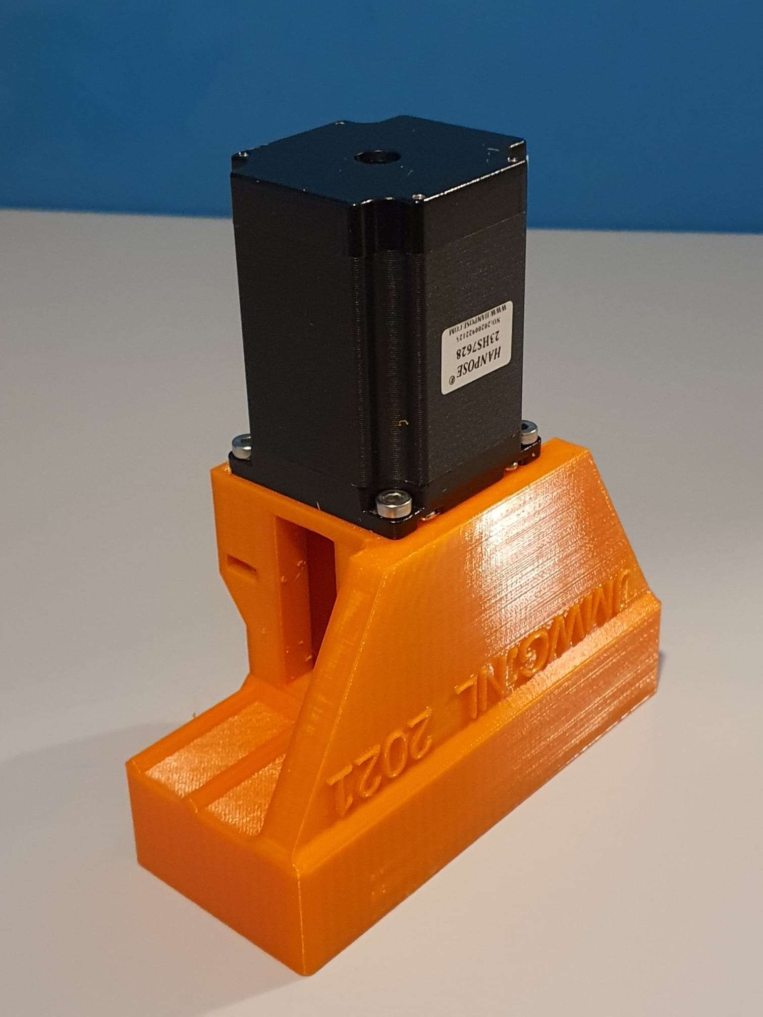
Then, on top of this, the Nema23 holder/mounting is projected.  Including all needed boltholes, nutholes and a side hole for tightening the coupler.

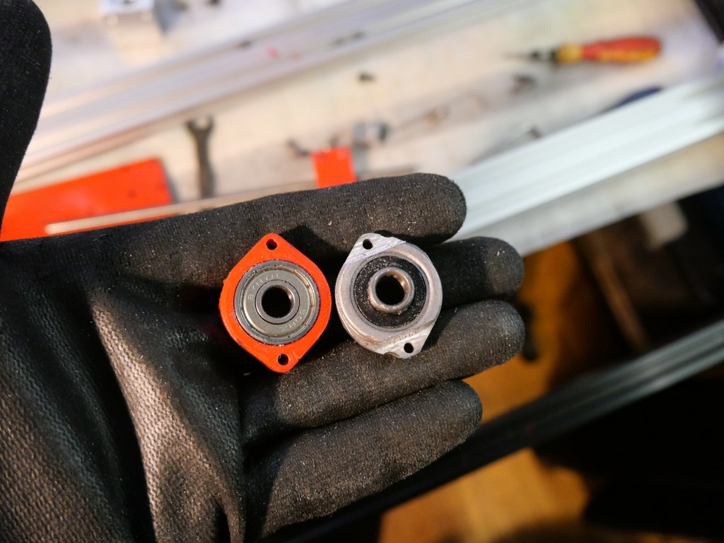
The leadscrew has an outside part for the handwheel we will use for CNC that is 10mm, and some thread 10mm for Z.  The thread is needed to be bolting the angular bearings (not meant for side torque) with some torque to the bearing holder.

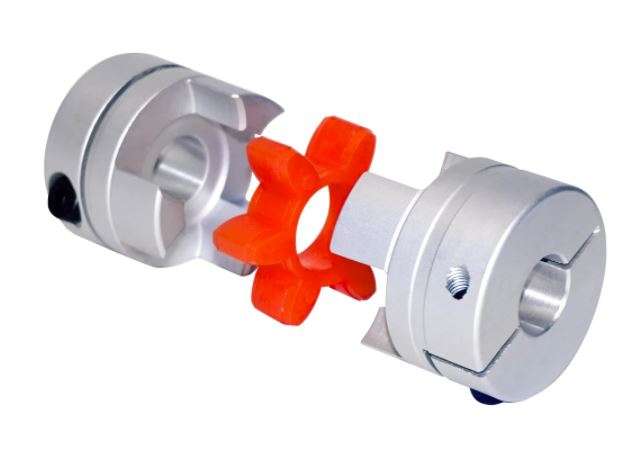
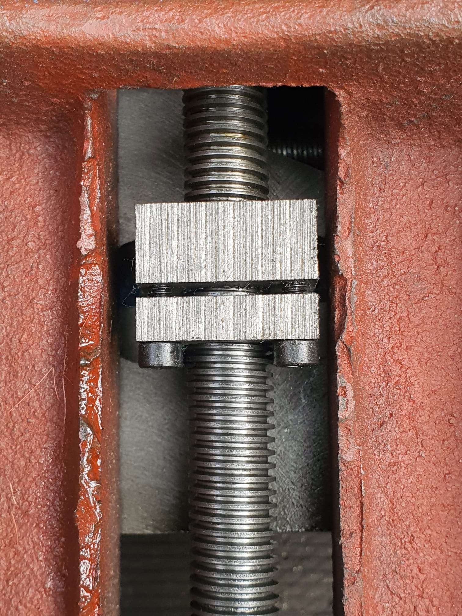
If you do direct drive, you need a special coupler that can be split in 2. Then, you first mount one part on the leadscrew with some rings between the mill and the coupler part so that the nut can be placed in the coupler.  If the thread is too long, grind some off.

Then, put the rubber (with centerhole)  back in the coupler’s mounted part and push the other part in the rubber, so the coupler is complete.

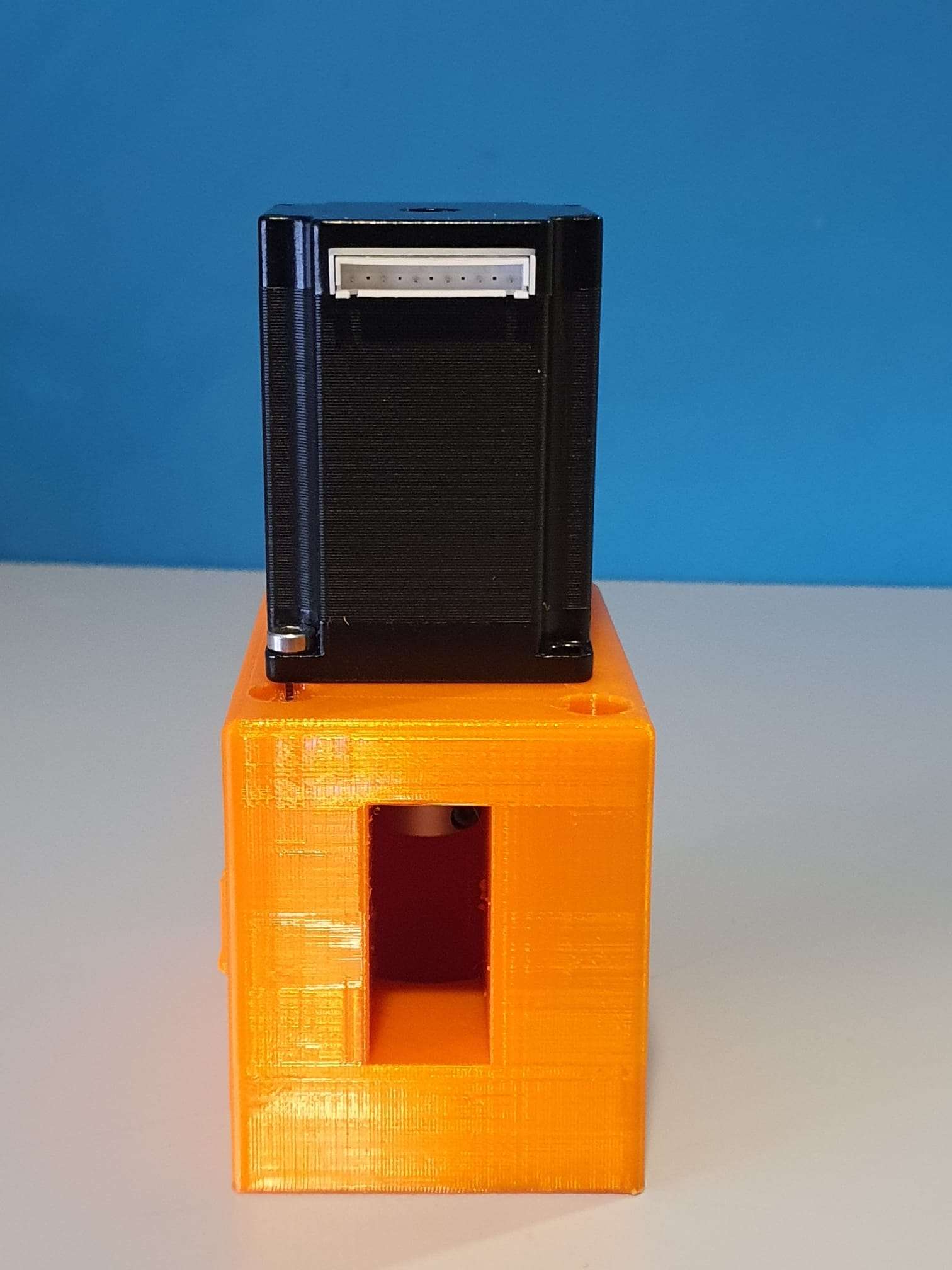
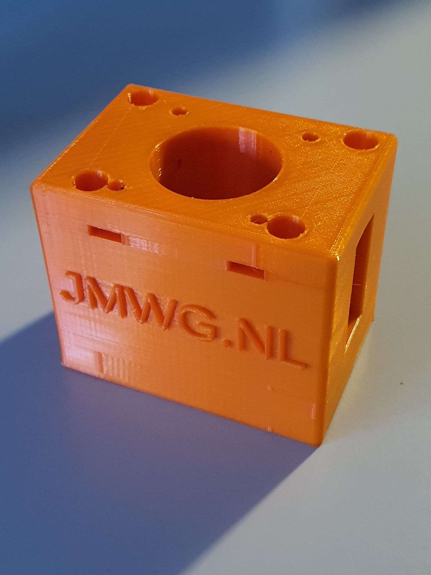
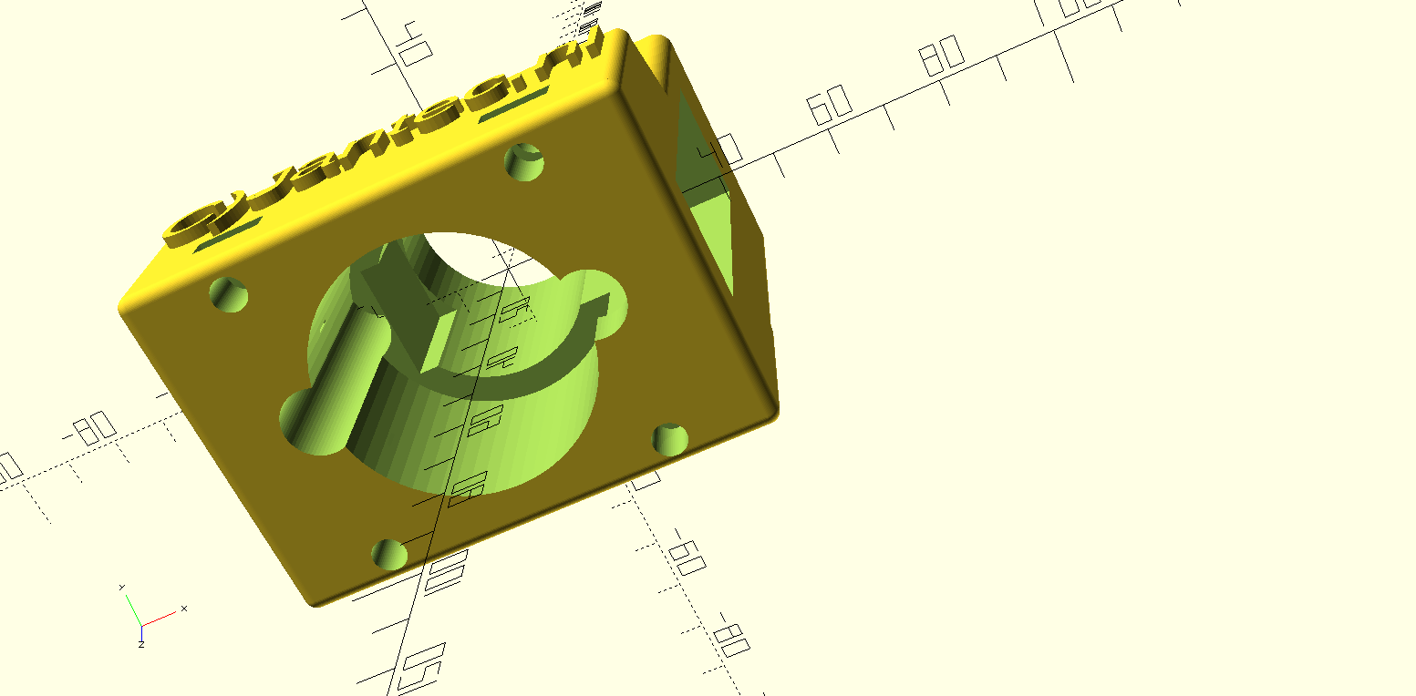
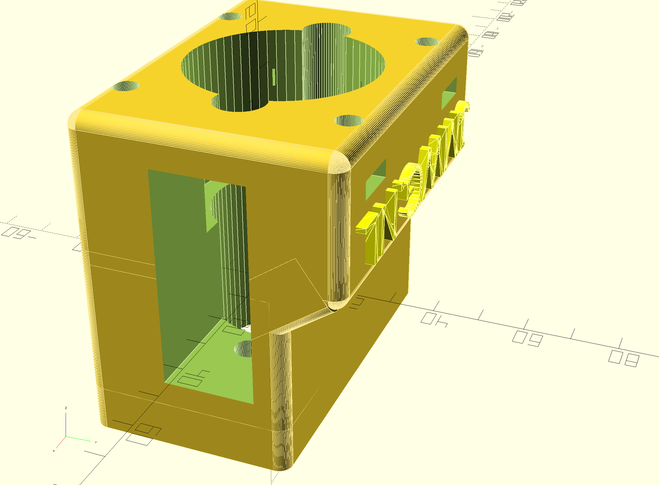
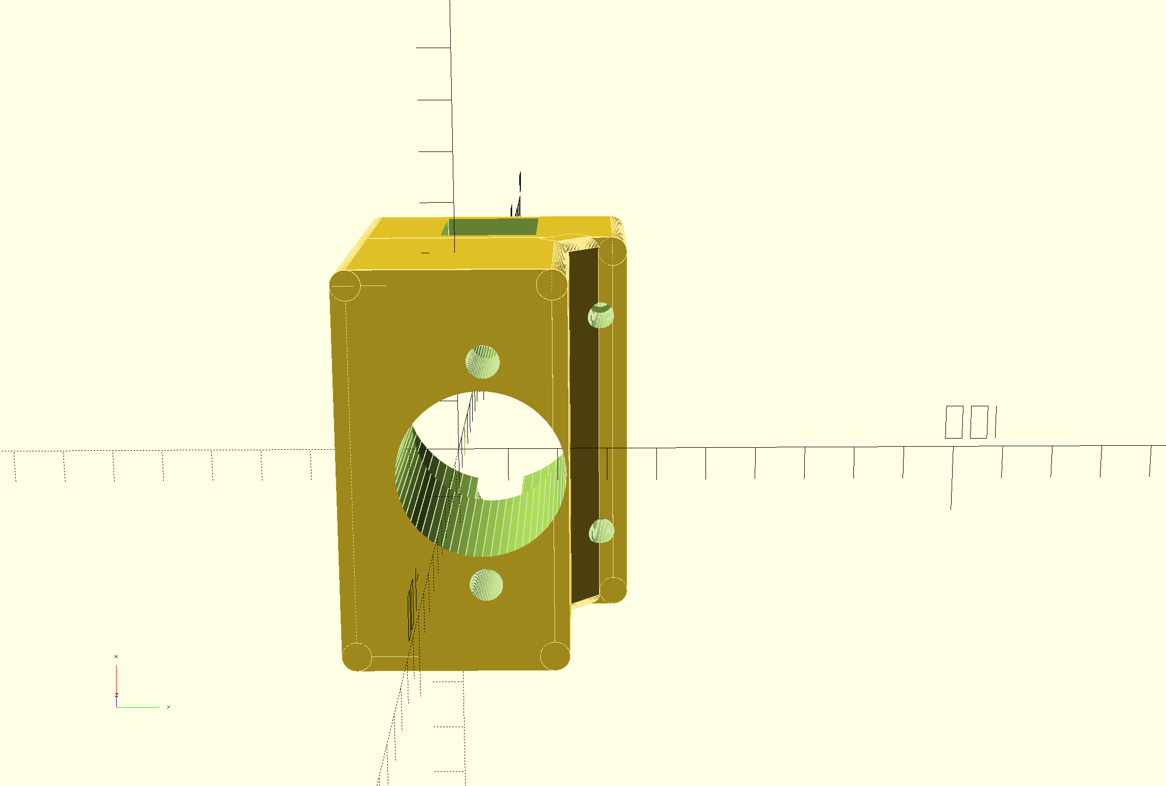
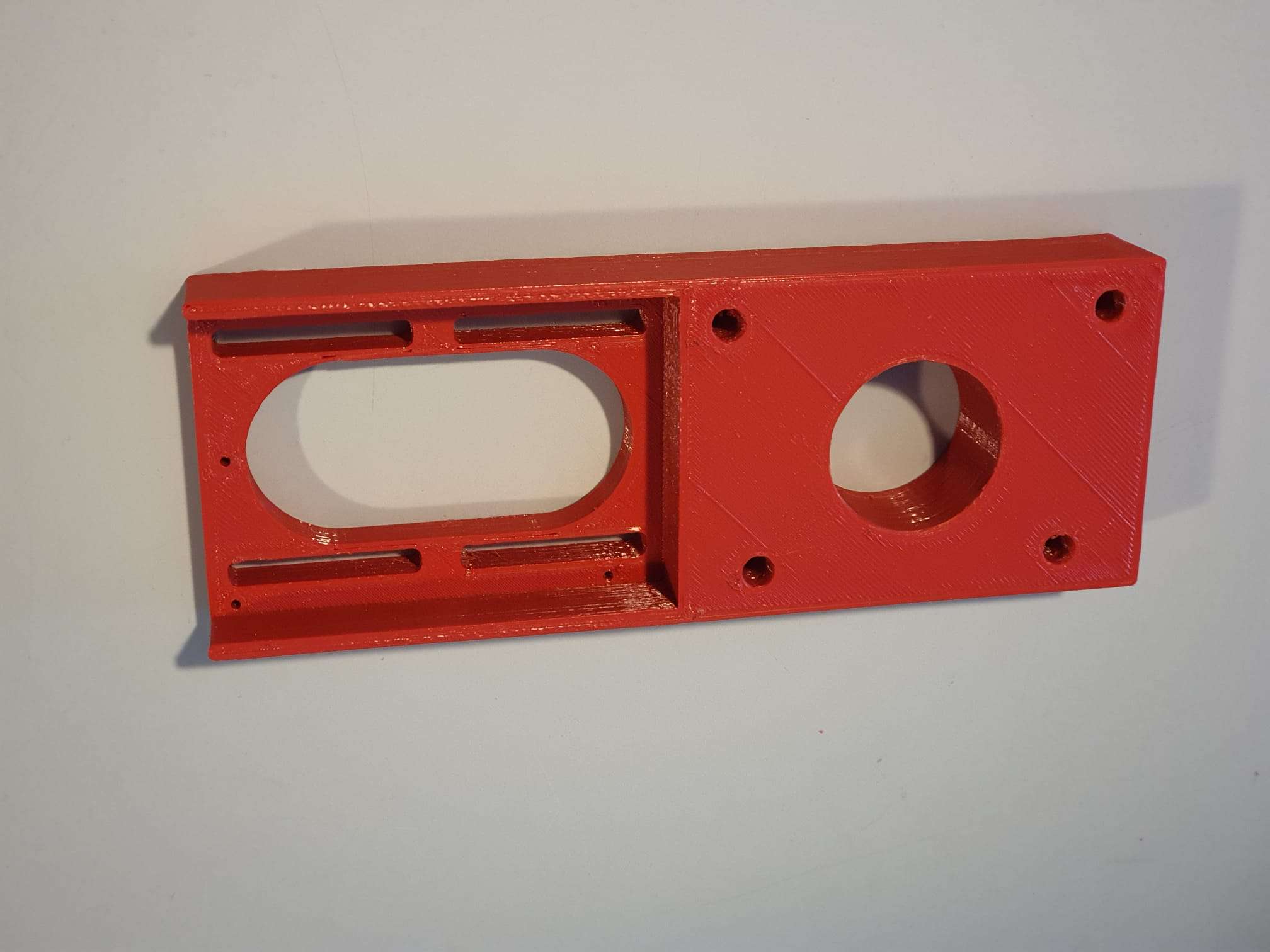
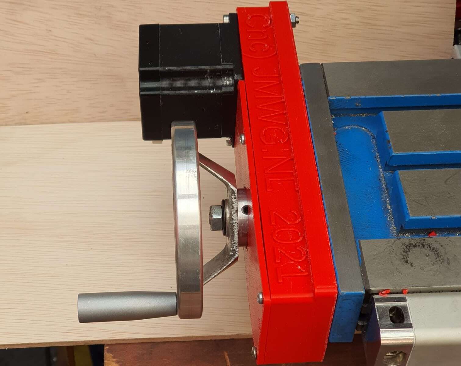
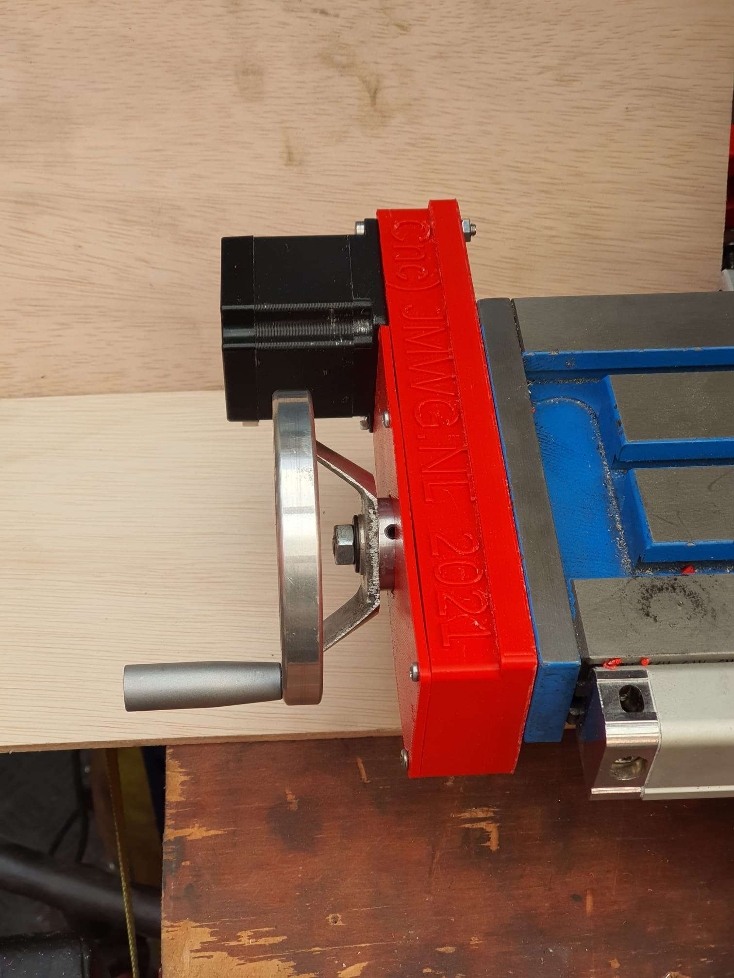
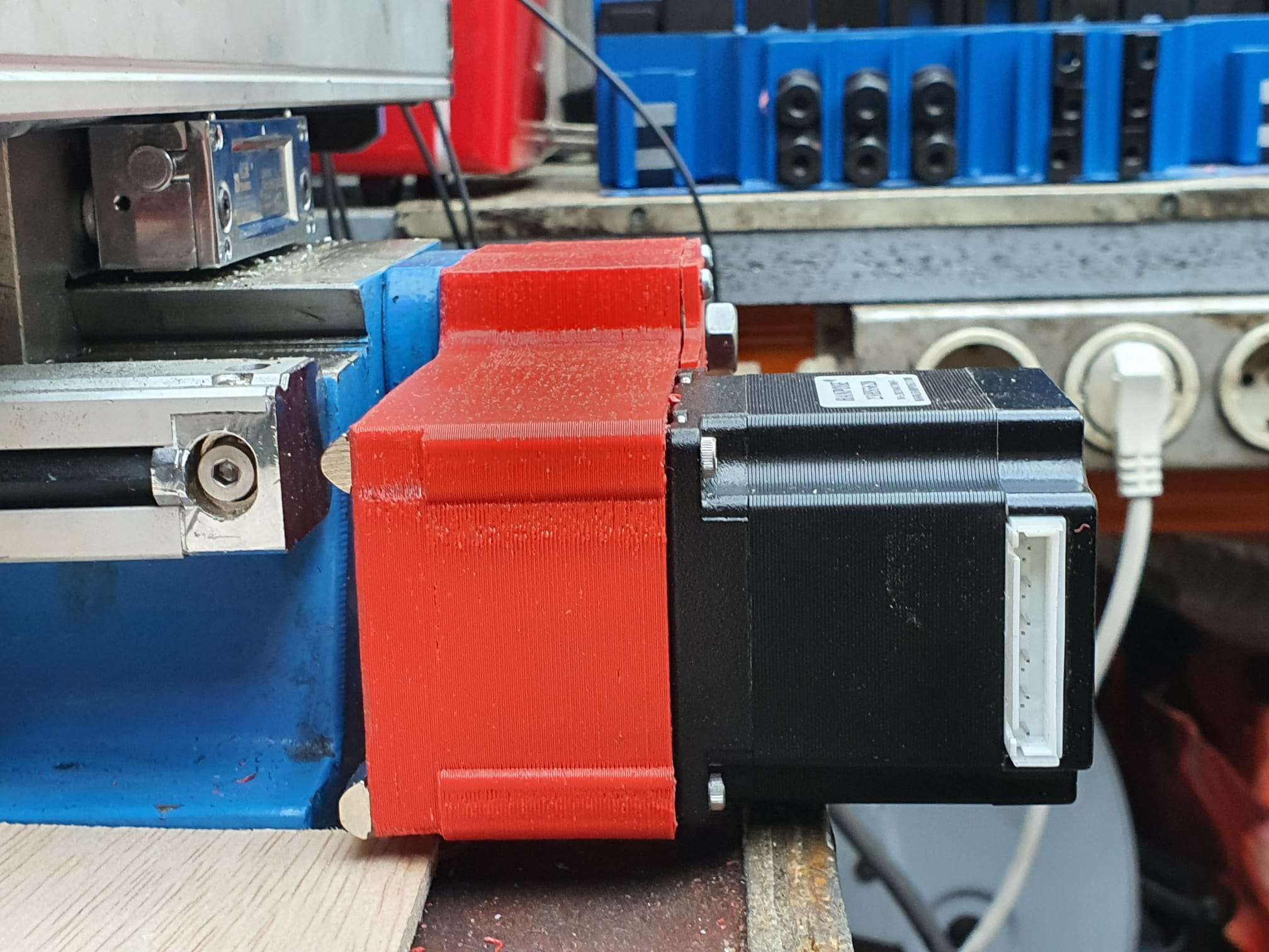
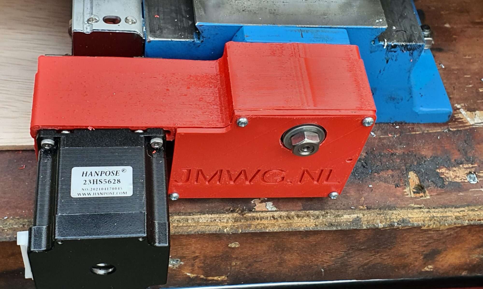
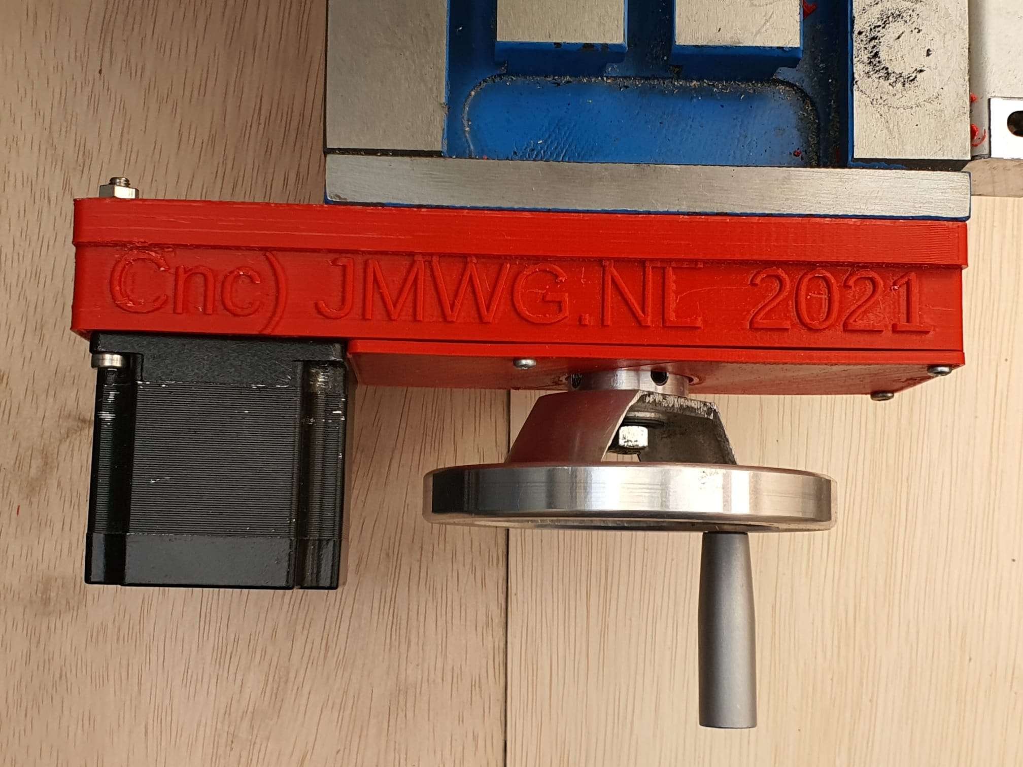
Then, mount the printed adapter with already mounted Nema23 motor on the Y-axis and push the Nema shaft in the coupler.  Use the adapter’s right hand side working window to torque the connector on the Nema shaft and you’re done!

Should you want to have a handwheel as well, this is possible but you will have to buy a stepper with an axis that is both at the front as the rear. (this is called ‘double shaft’ but is actually a longer shaft, obviously.]

GOTO the X-axis Direct Drive adapter

GOTO the Y-axis Direct Drive adapter


Minimill CNC conversion WMD16LV X-axis adapter for NEMA23 direct drive

While I was making my CNC adapter plates with teethed wheels and belts, I discovered that not much exists that is ready to use for these conversions.

DOWNLOAD:

MINIMILL_BF16L CNC_X_adapter direct drive 2022_07_25_V1_5-jantec.nl

I am therefore also making direct drive adapter parts, to try this out.


This is the second piece I make for direct drive, for the X-axis.

The leadscrew has an outside part for the handwheel we will use for CNC that is 10mm, and some thread 8mm.  The thread is needed to be bolting the angular bearings (not meant for side torque) with some torque to the bearing holder.

If you do direct drive, you need a special coupler that can be split in 2. Then, you first mount one part on the leadscrew with some rings between the mill and the coupler part so that the nut can be placed in the coupler.  If the thread is too long, grind some off.

Then, put the rubber (with centerhole)  back in the coupler’s mounted part and push the other part in the rubber, so the coupler is complete.

Then, mount the printed adapter with already mounted Nema23 motor on the Y-axis and push the Nema shaft in the coupler.  Use the adapter’s right hand side working window to torque the connector on the Nema shaft and you’re done!

Should you want to have a handwheel as well, this is possible but you will have to buy a stepper with an axis that is both at the front as the rear. (this is called ‘double shaft’ but is actually a longer shaft, obviously.

GOTO the Direct Drive Y-axis adapter

GOTO the Direct Drive Z-axis adapter

DOWNLOAD the latest version of the STL printfiles 

Please donate $1 to my paypal account if you use (parts of) my developed materials so I can continue to share nice stuff for you to download

Minimill CNC conversion WMD16LV Y-axis adapter for NEMA23 direct drive

While I was making my CNC adapter plates with teethed wheels and belts, I discovered that not much exists that is ready to use for these conversions.

DOWNLOAD:

MINIMILL_BF16L CNC_Y_adapter direct 2022_07_25_V1_5-jantec.nl

I am therefore also making direct drive adapter parts, to try this out.

This is the first one, starting with the most difficult one.  The rest will be added soon.

Version 1.2 which is 15 mm shorter and much more robust:


The leadscrew has an outside part for the handwheel we will use for CNC that is 10mm, and some thread 8mm.  The thread is needed to be bolting the angular bearings (not meant for side torque) with some torque to the bearing holder.

If you do direct drive, you need a special coupler that can be split in 2. Then, you first mount one part on the leadscrew with some rings between the mill and the coupler part so that the nut can be place in the coupler.  If the thread is too long, grind some off.

Then, put the rubber (with centerhole)  back in the coupler’s mounted part and push the other part in the rubber, so the coupler is complete.

Then, mount the printed adapter with already mounted Nema23 motor on the Y-axis and push the Nema shaft in the coupler.  Use the adapter’s right hand side working window to torque the connector on the Nema shaft and you’re done!

Should you want to have a handwheel as well, you will have to buy a stepper with an axis that is both at the front as the rear. (this is called ‘double shaft’ but is actually a longer shaft, obviously.

OR- my latest design works a bit different: first put a couple of  10mm rings on the leadscrew’s 10mm axle, and then screw a  threaded RVS tube with an outer diameter of 12mm, 25 mm long and internal 8mm thread on the axle.  This goed into a 12 to 8mm coupler and this coupler connects to a NEMA23 stepper motor with an 8 mm axis.  It does get a bit lengthy but it works very well.  Just threadlock the RVS threaded tube to the leadscrew’s 8mm threaded end and it will run OK!

This is the last version, based on the above setup:


GOTO the Dirext Drive X-adapter

GOTO the Direct Drive Z-adapter

DOWNLOAD the latest version of the STL printfiles 

Please donate $1 to my paypal account if you use (parts of) my developed materials so I can continue to share nice stuff for you to download

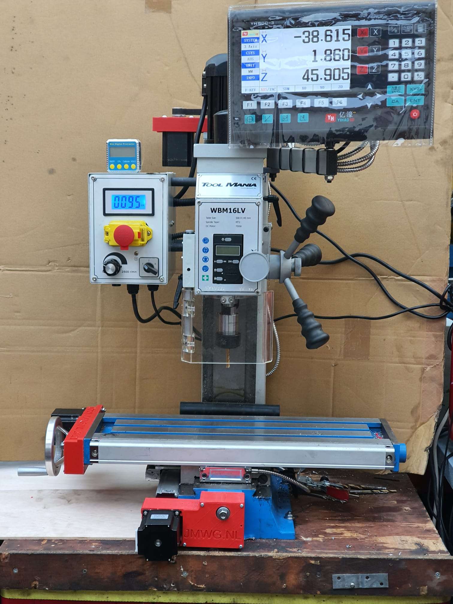
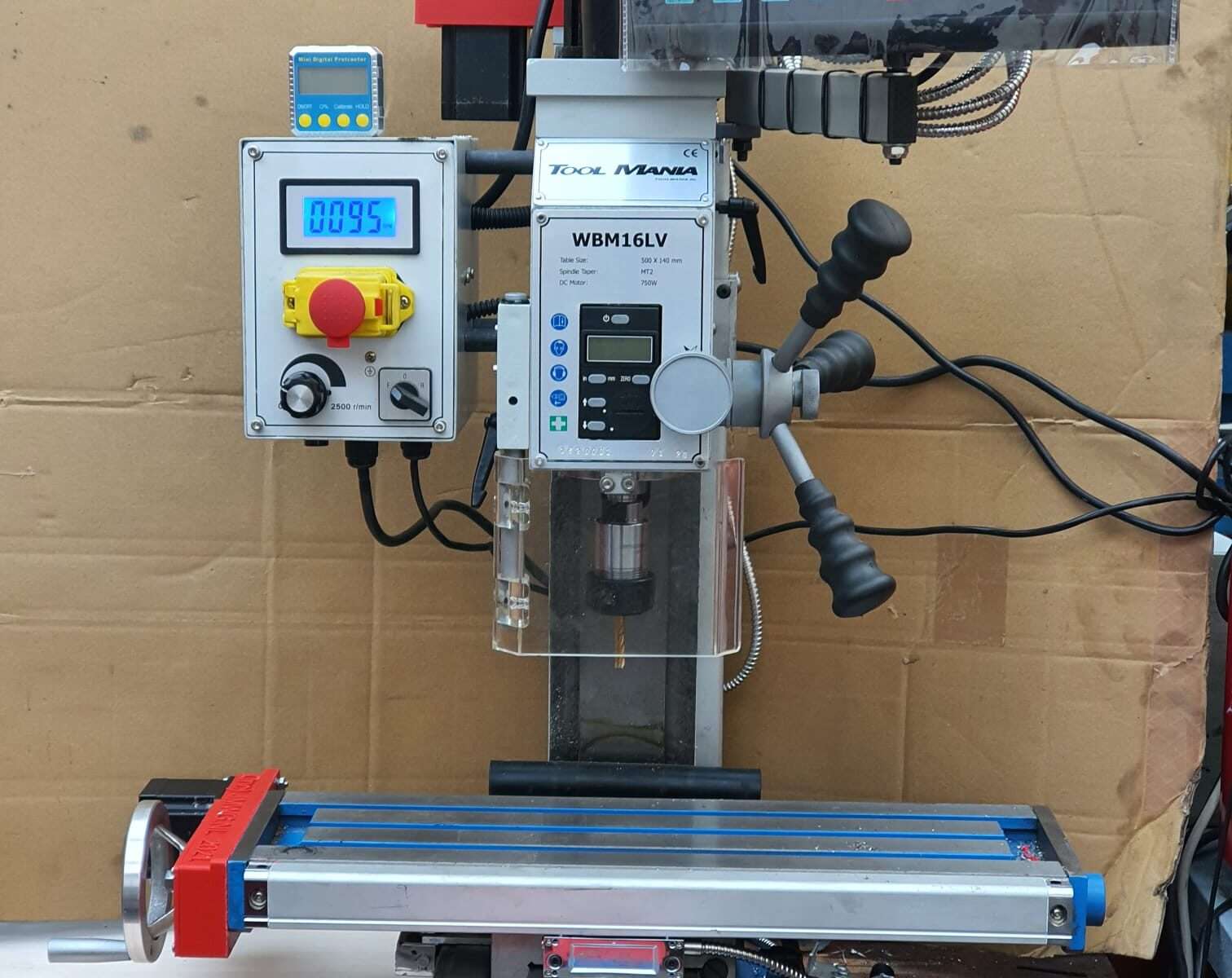
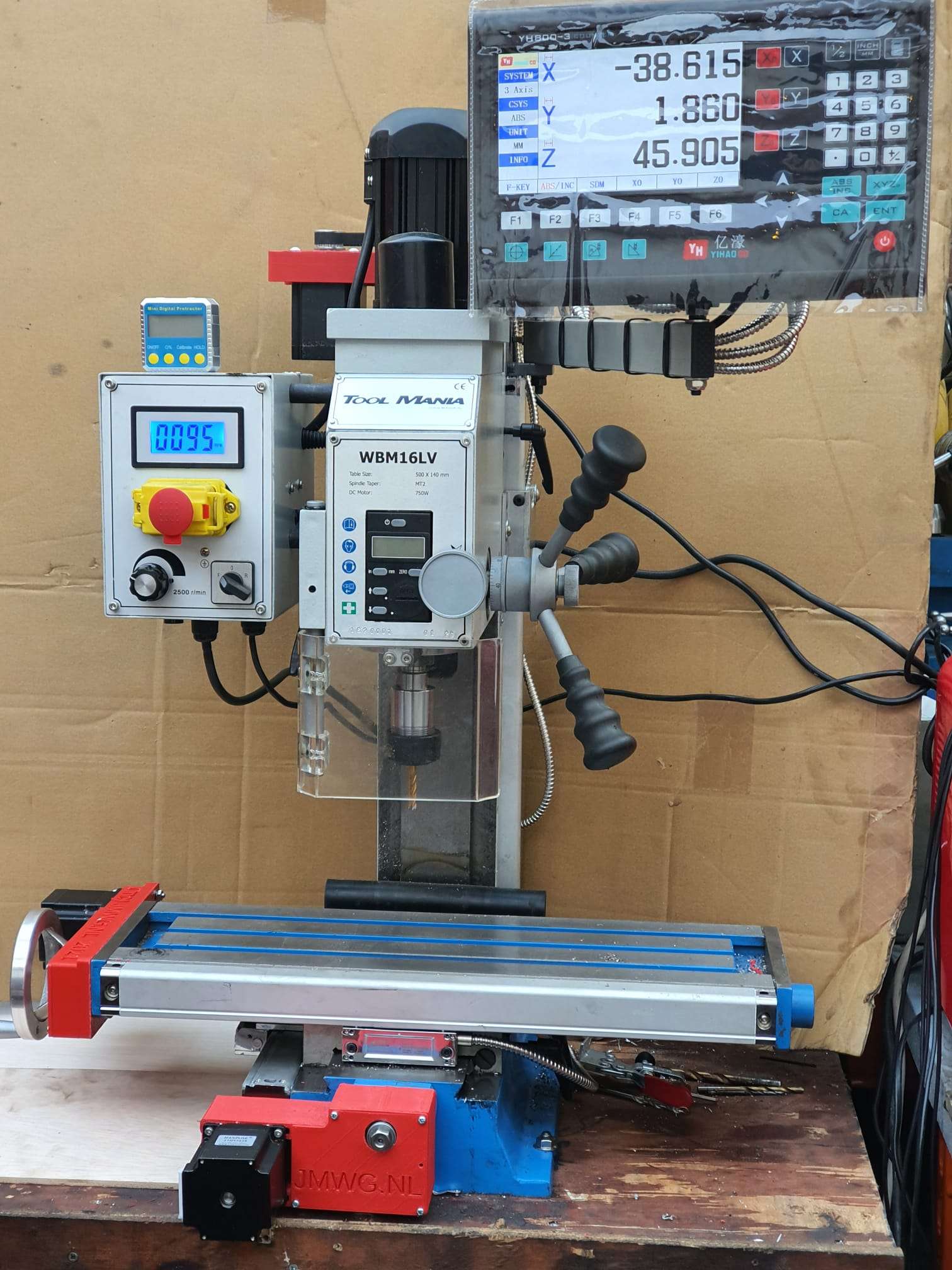
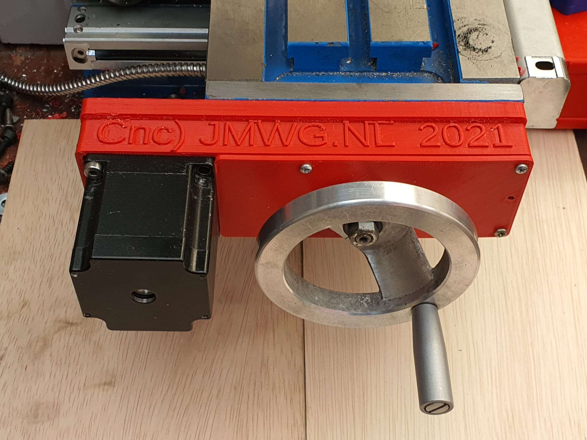
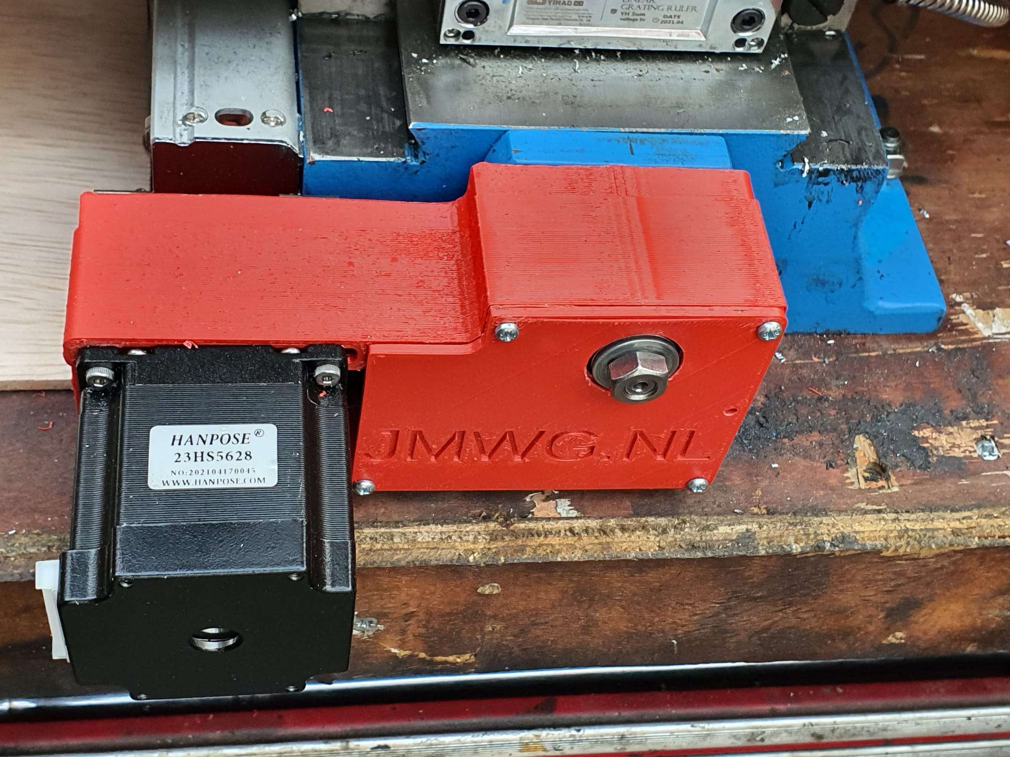
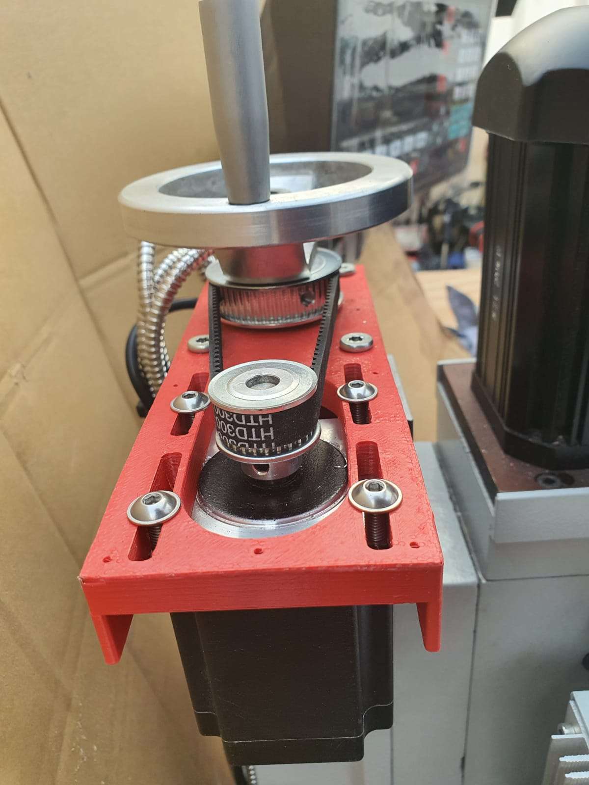
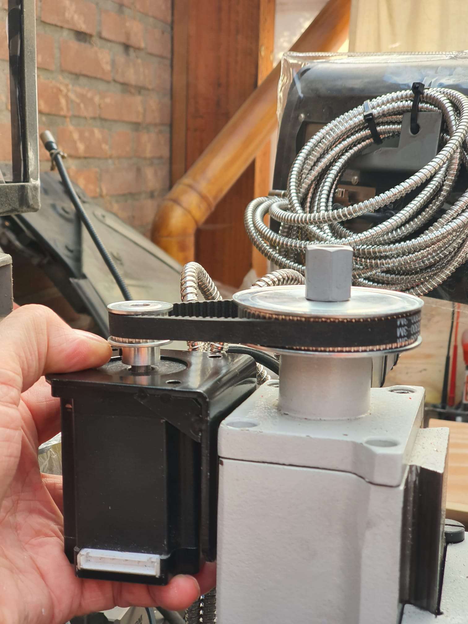
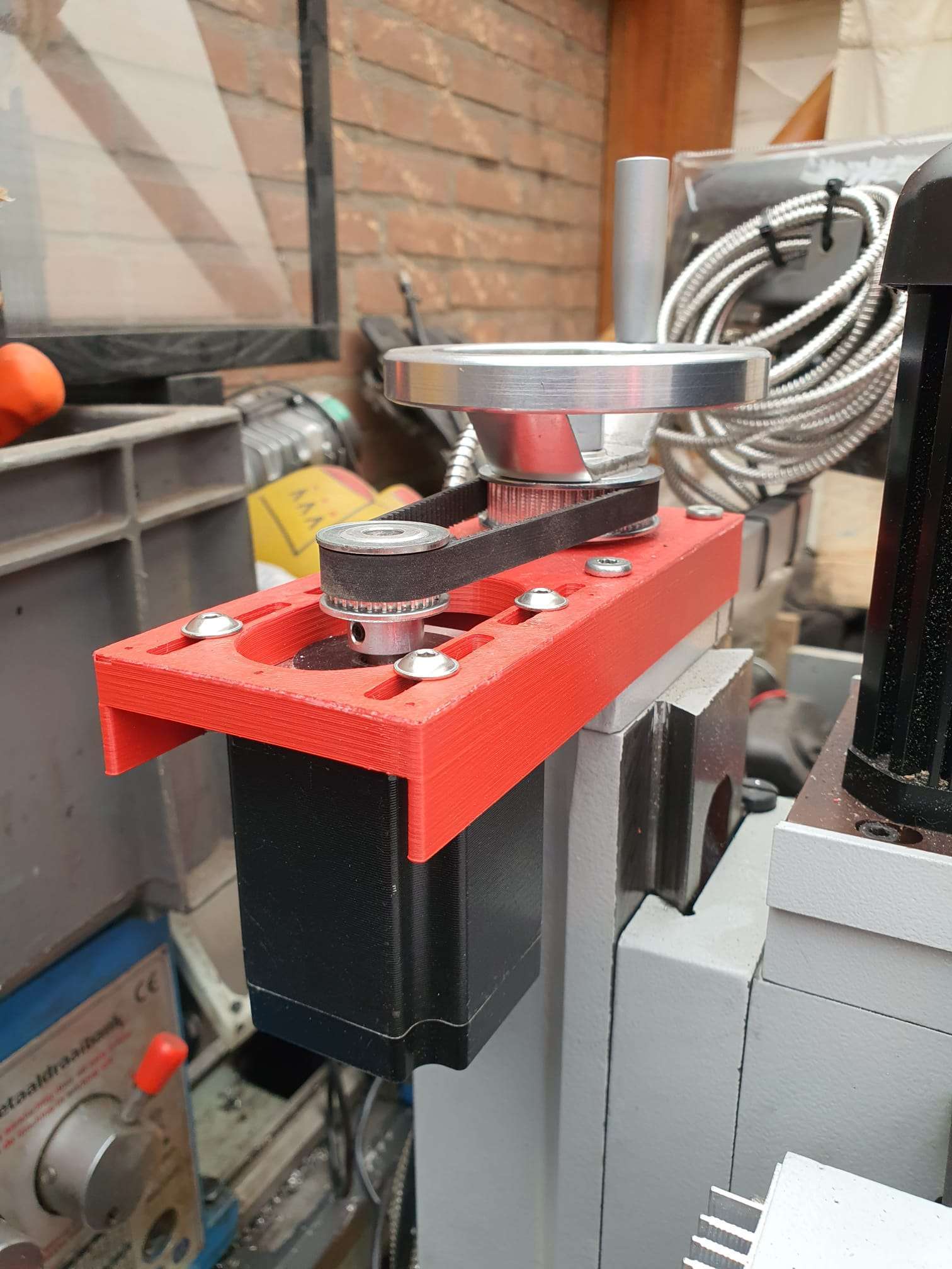
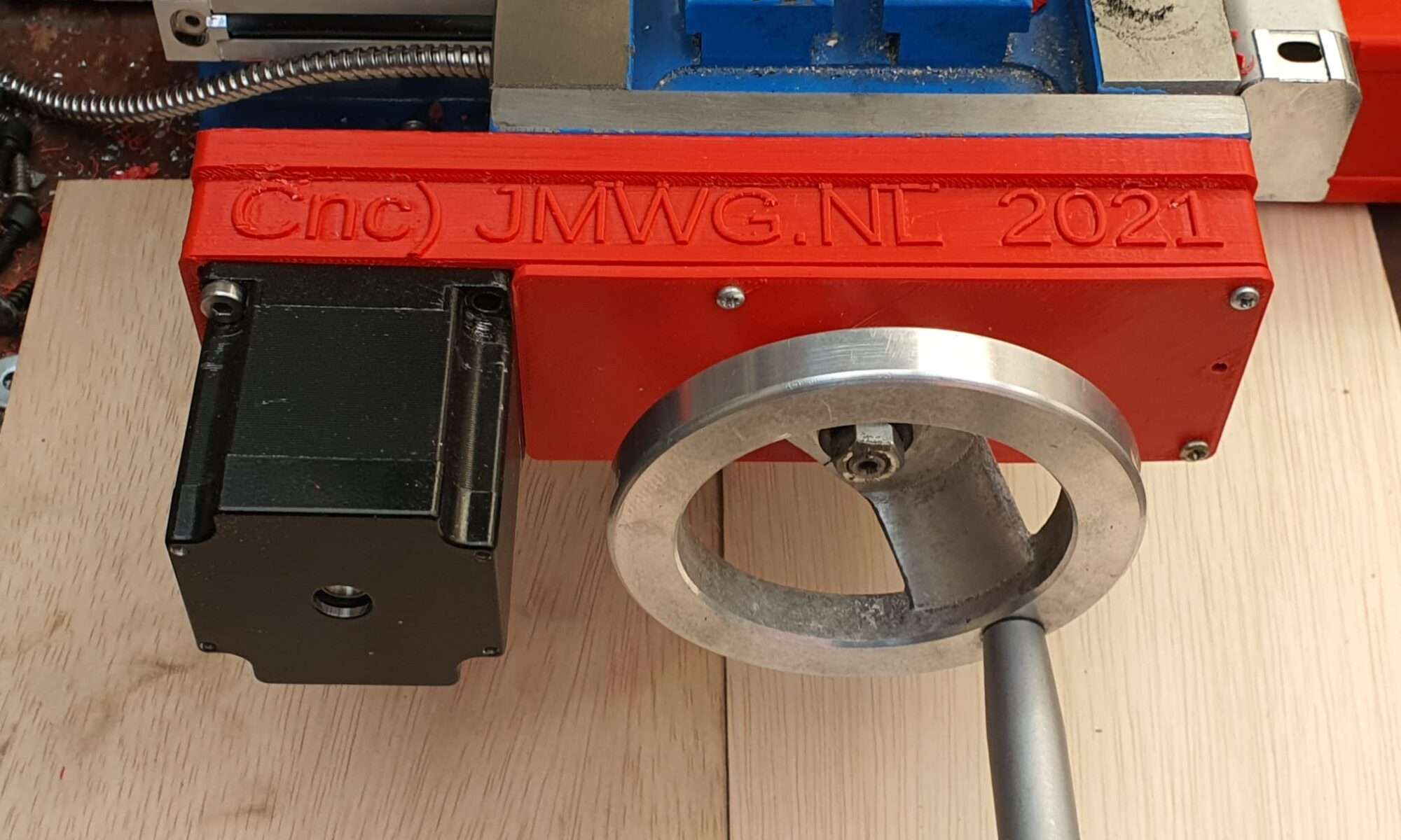
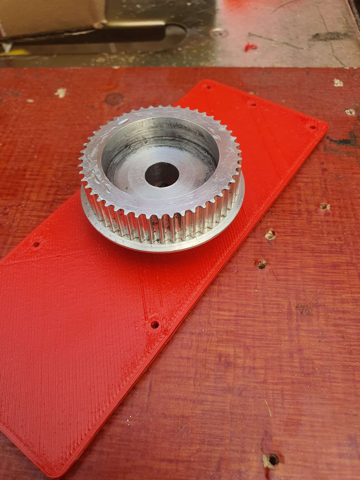
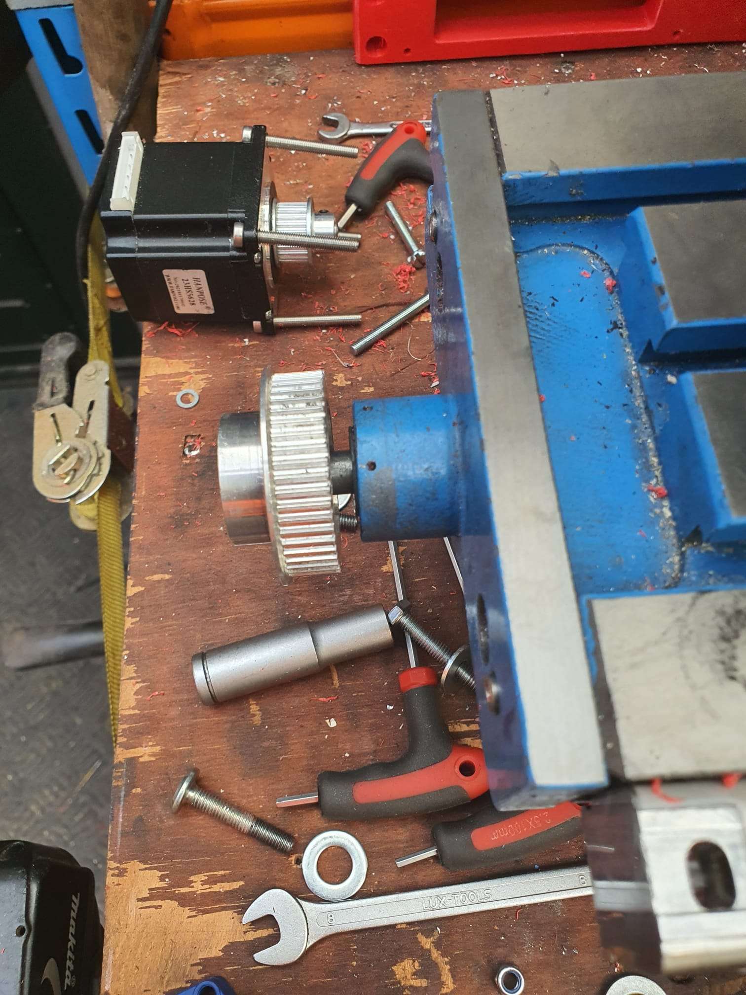
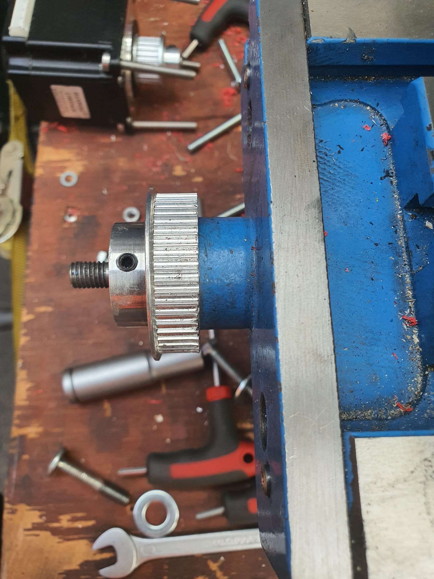
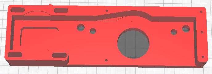
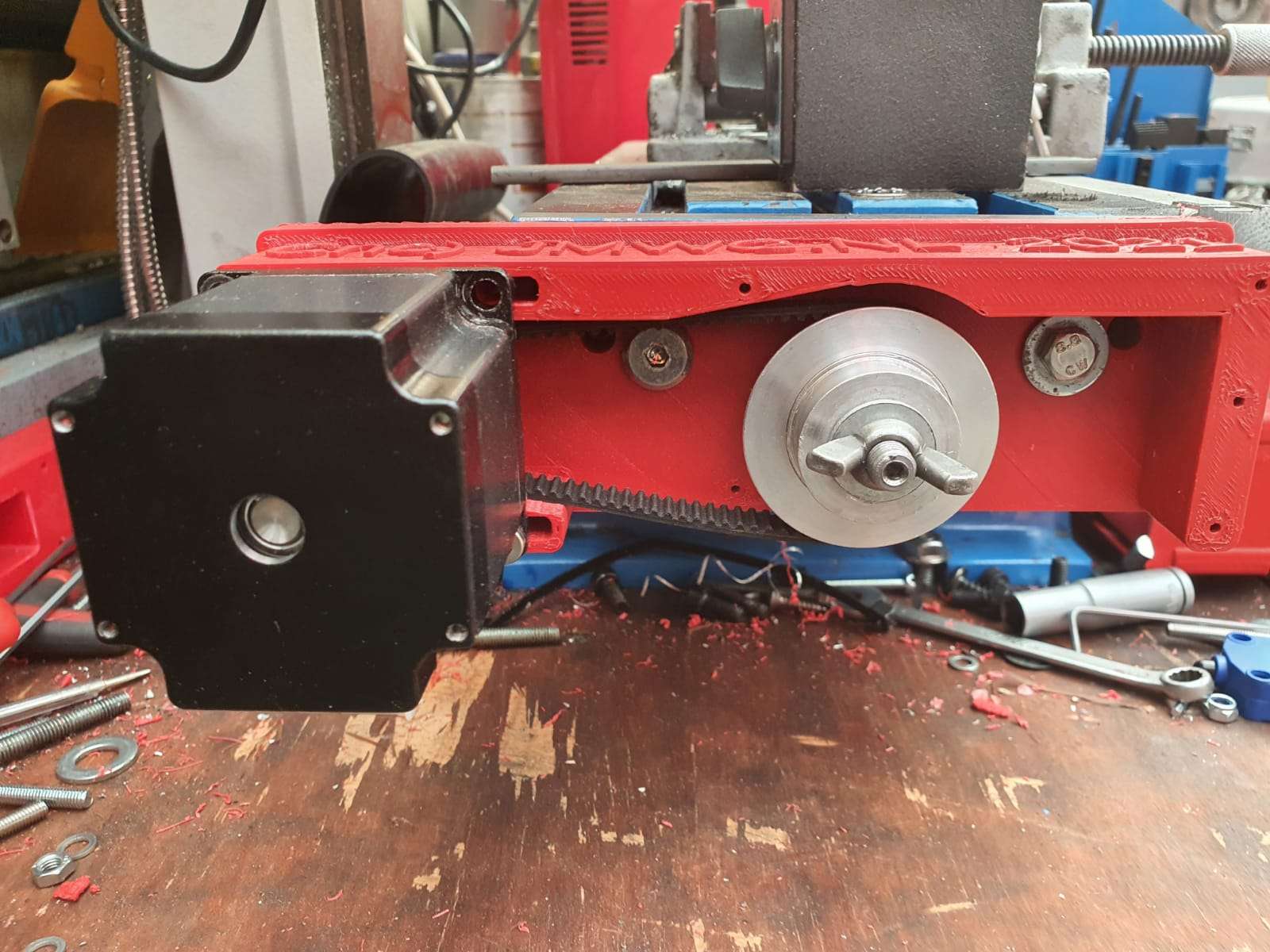
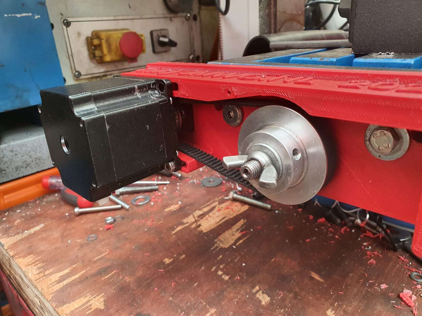
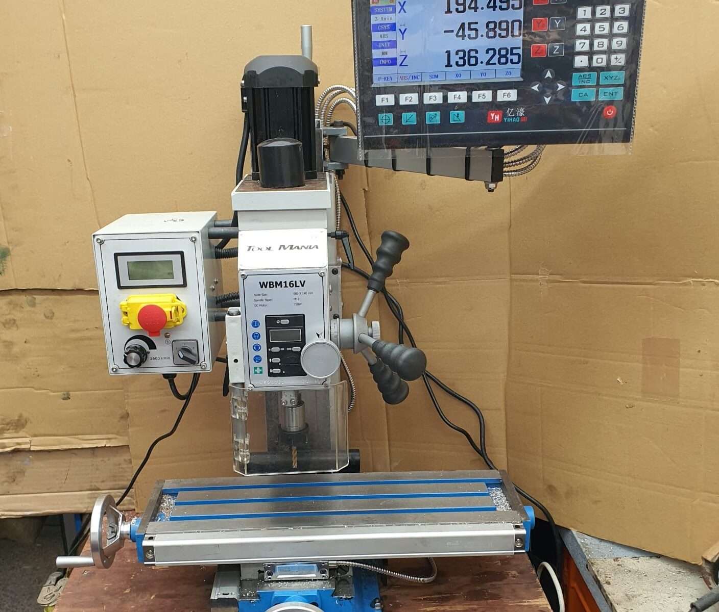
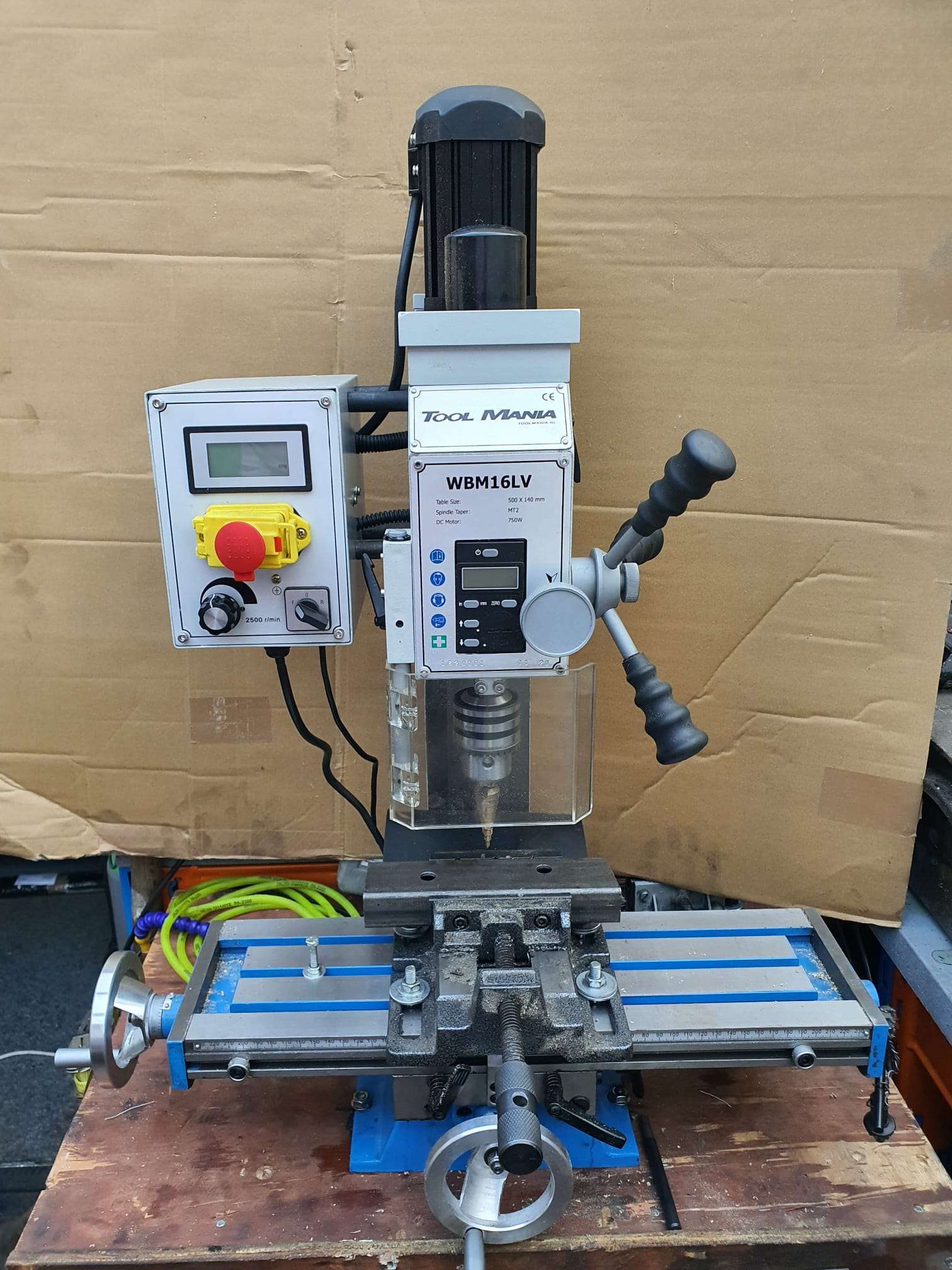
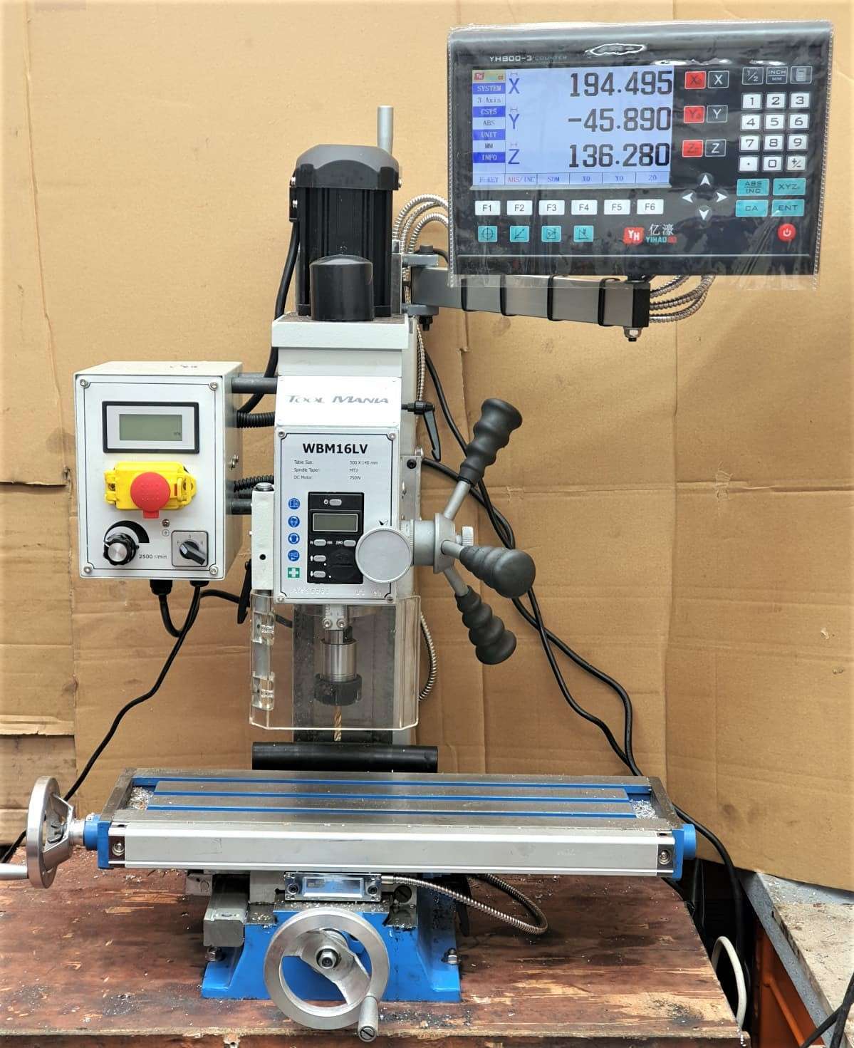
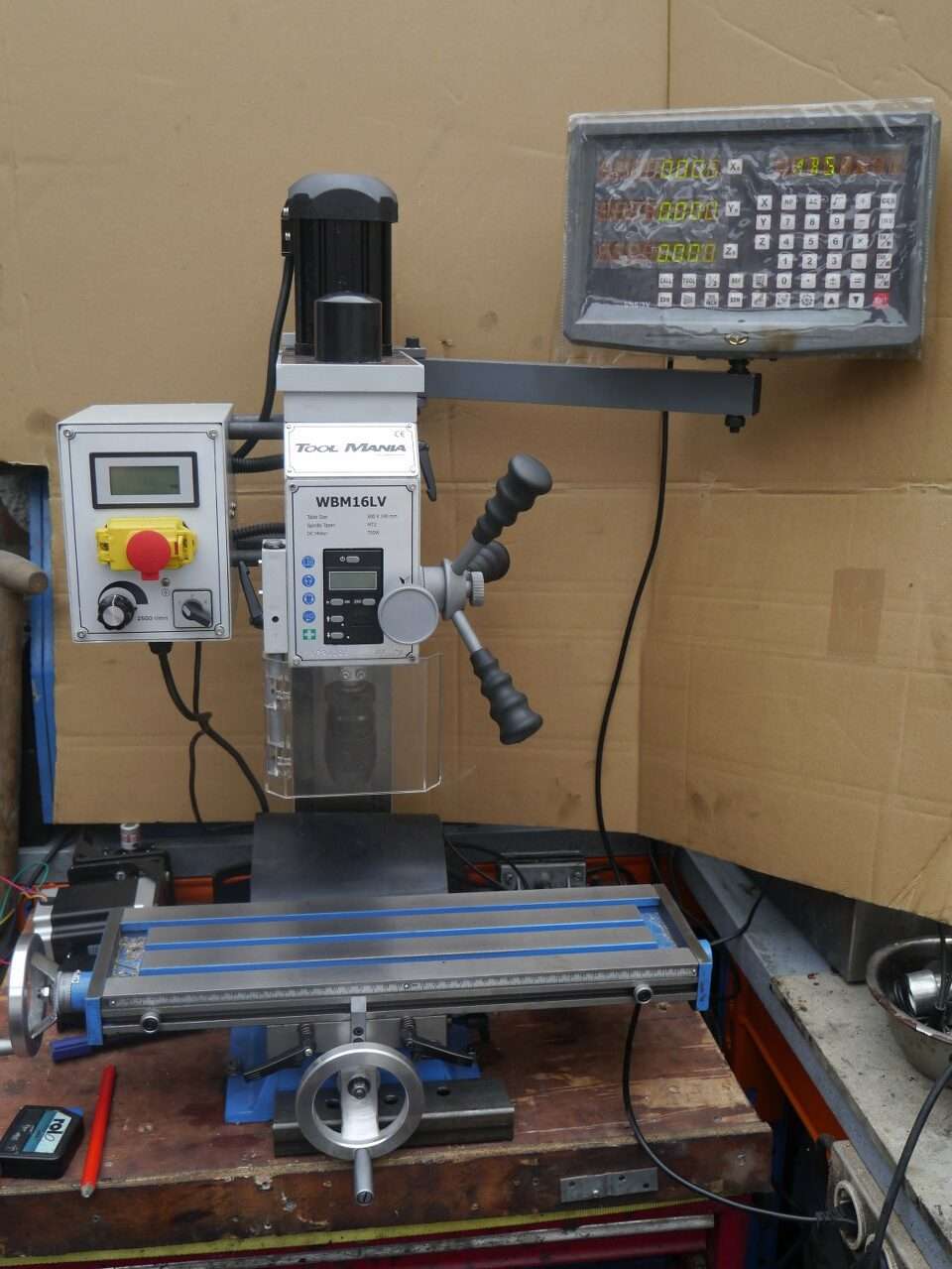
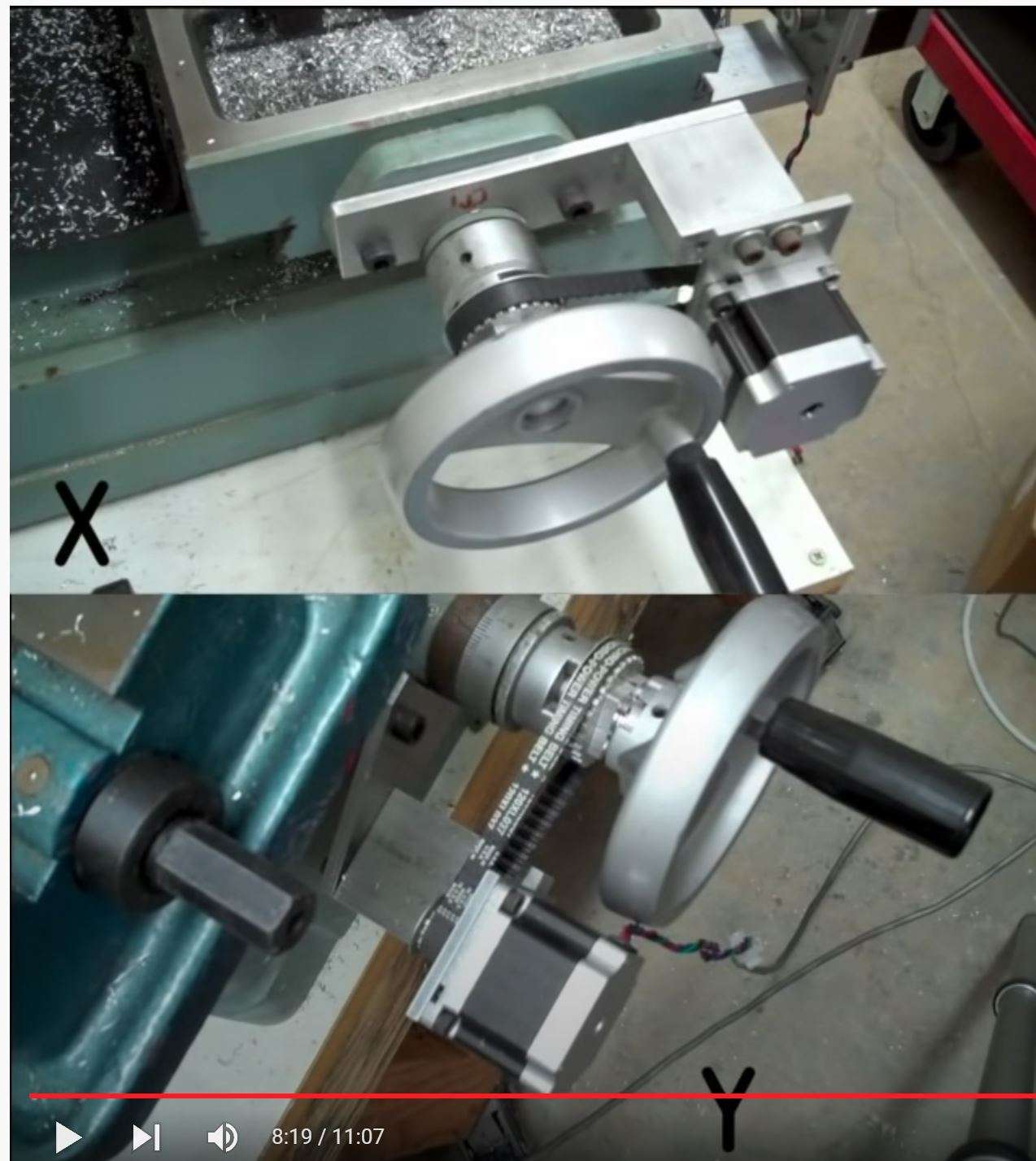
CNC conversion of my Toolmania WBM16LV (TM BF 16) mill with NEMA23 steppers, 3dprinted adapters, teethed wheels and teethed belts

Before My Toolmania WBM16LV milling machine was delivered I already had plans to convert it to a CNC milling machine.

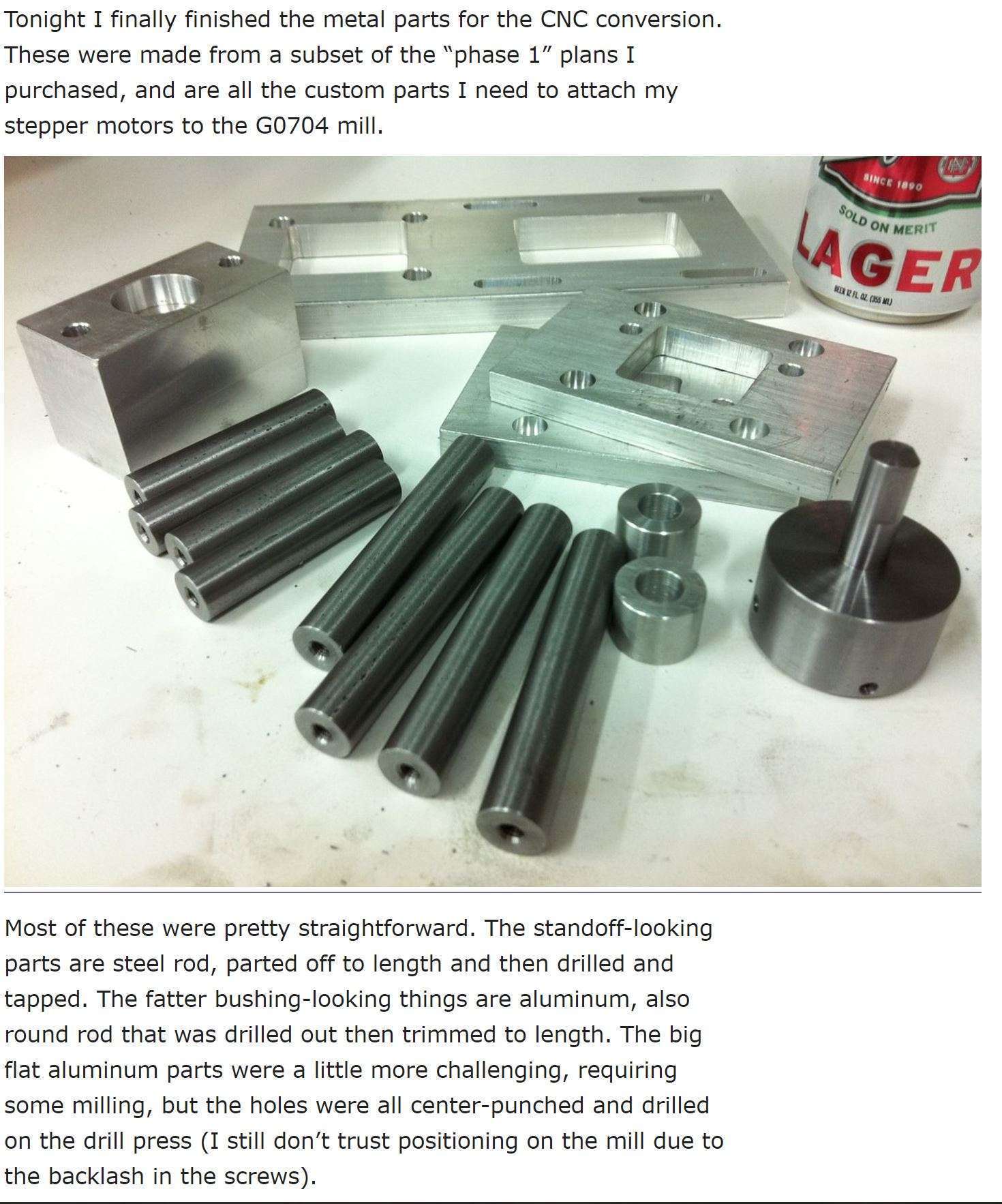
I do have some experience with 3d printing, and I have 2 CNC routers up and running, like the Indymill.  So, the conversion of this mill will not be difficult in the Technical sense.  But- making the perfect designs for the adapter plates of the Y- and X- axes proved to be a lot more work than I expected.

Please donate $1 to my paypal account if you use (parts of) my developed materials so I can continue to share nice stuff for you to download

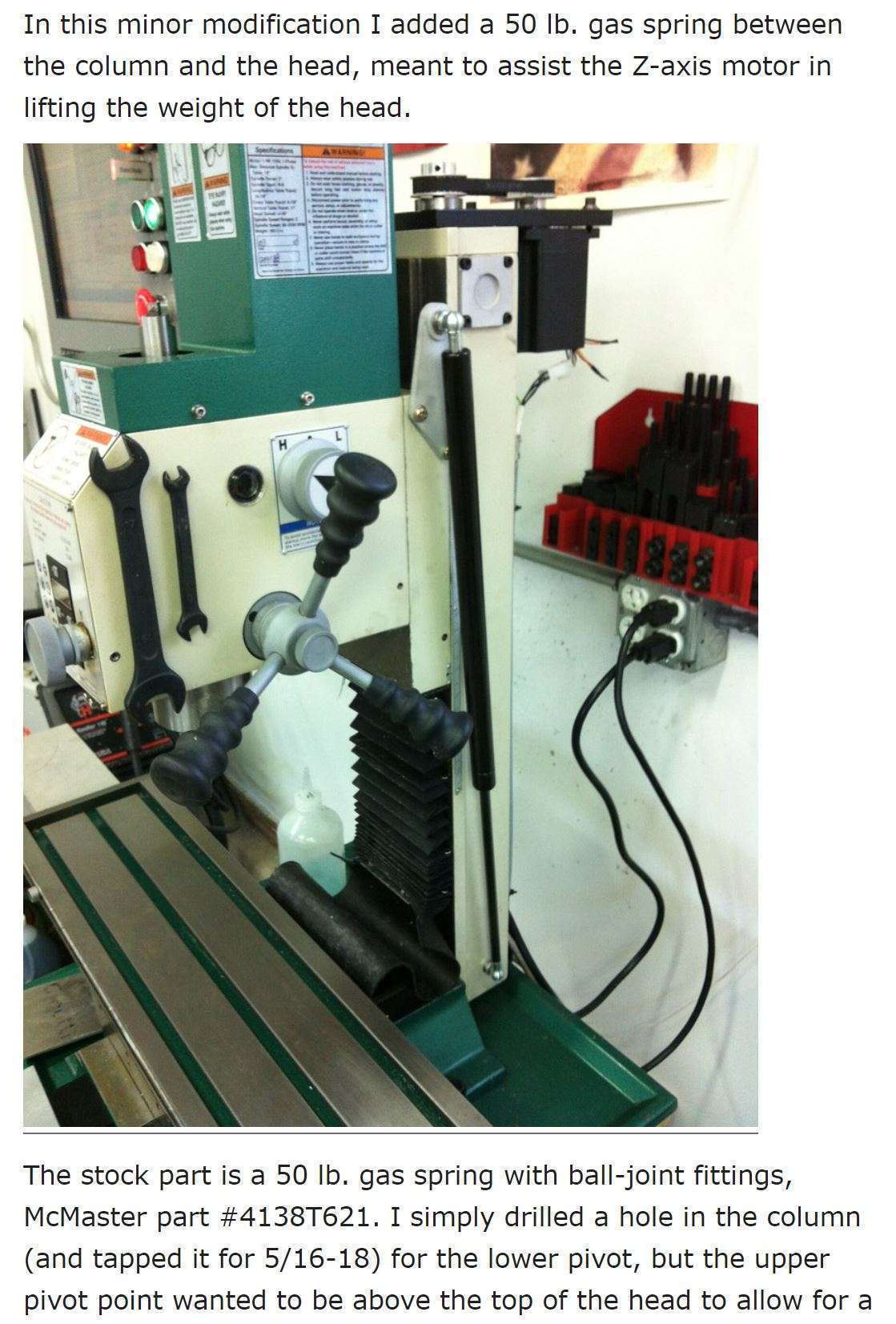
The column cutter is already equipped with glass scales with digital readout.  Furthermore, there is a gas spring mounted on the Z-column so that not all the weight is in the way when moving back and forth.  Also an automatic lubrication system for the slides of X, Y and Z-axis will be mounted.)

DOWNLOAD ALL MY CNC TEETHED ADAPTER DESIGNS  as .STL files

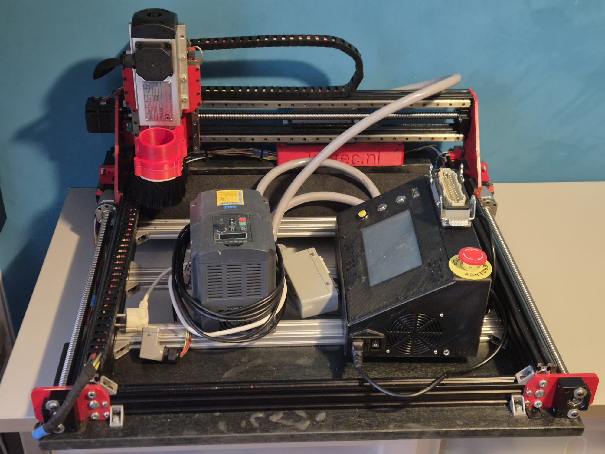
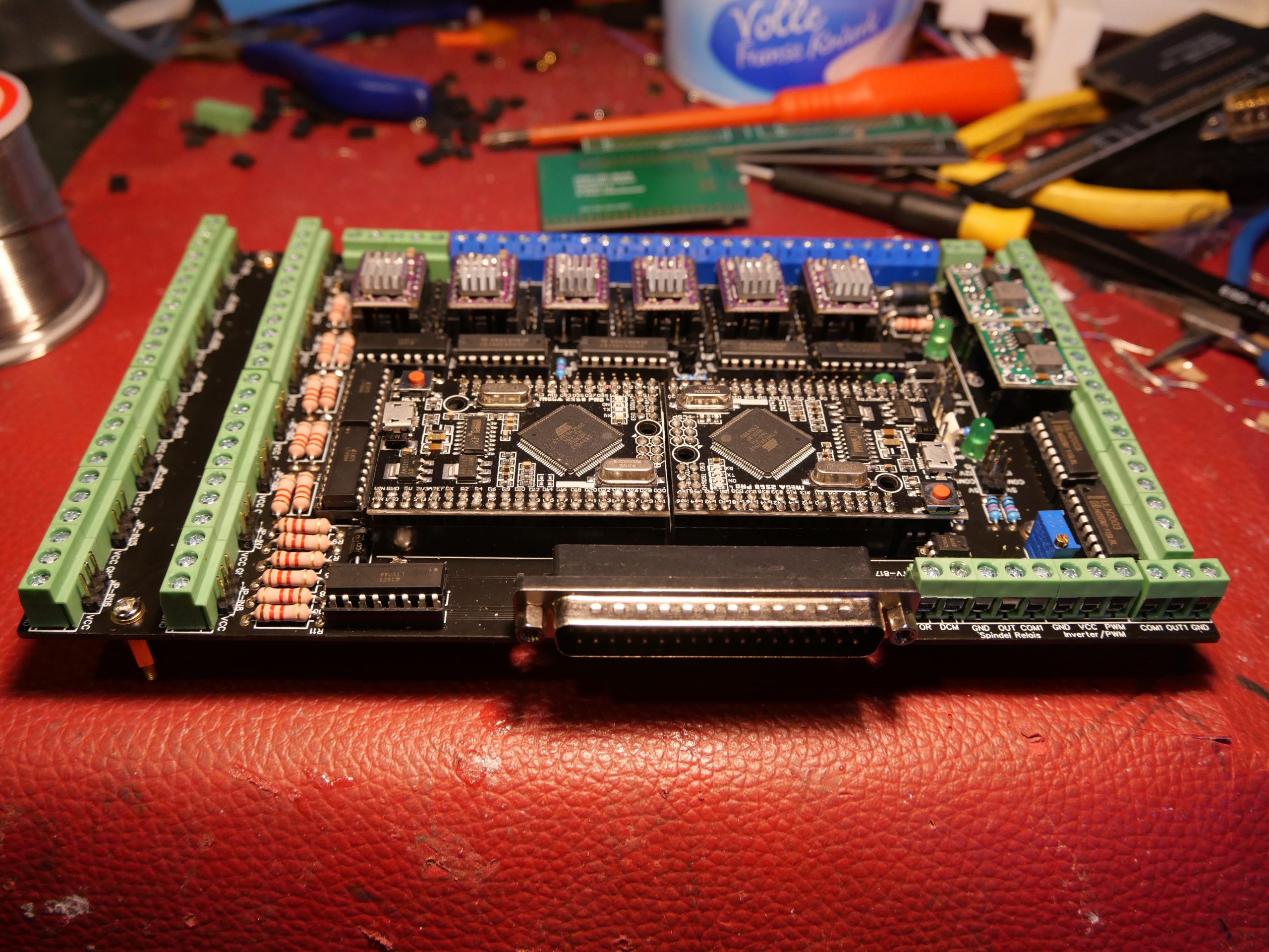
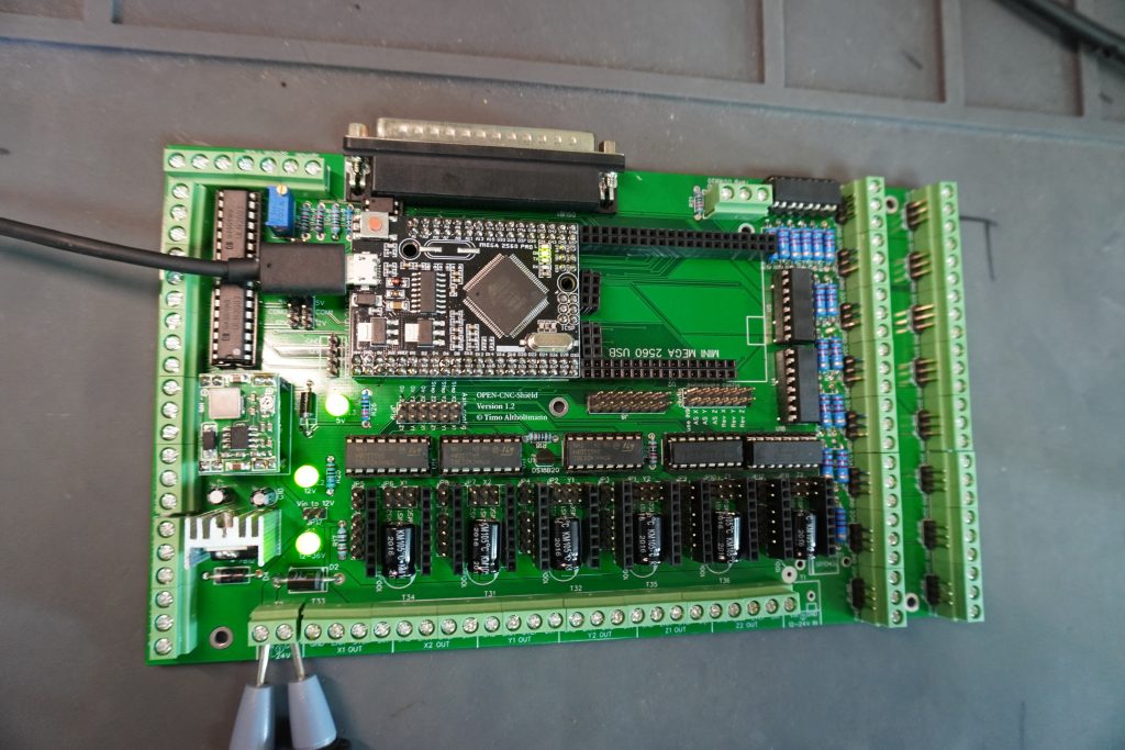
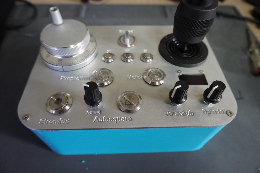
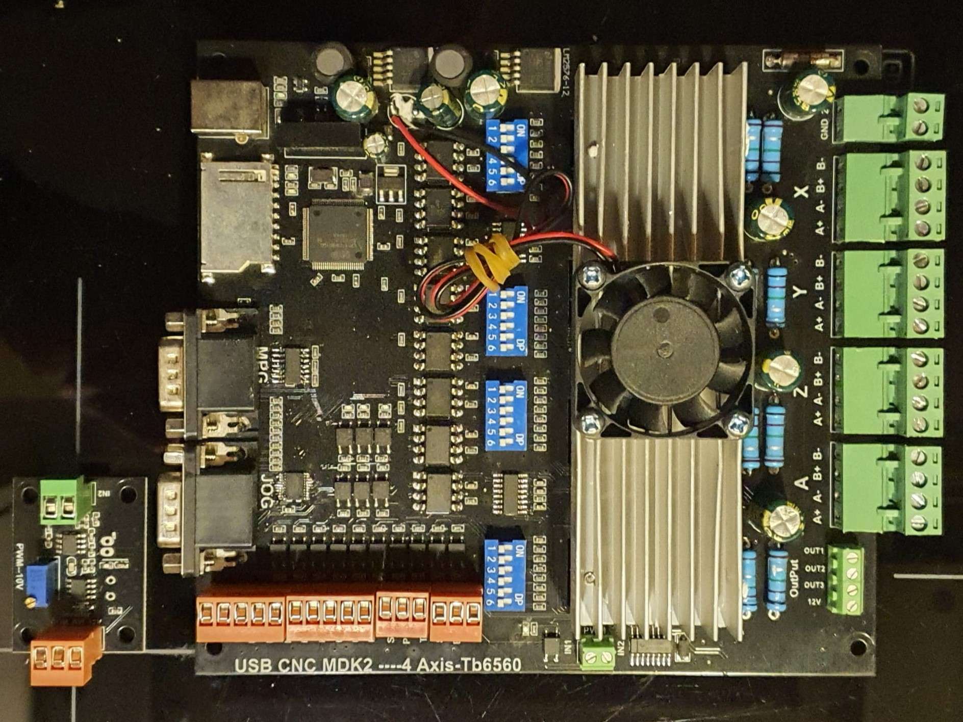
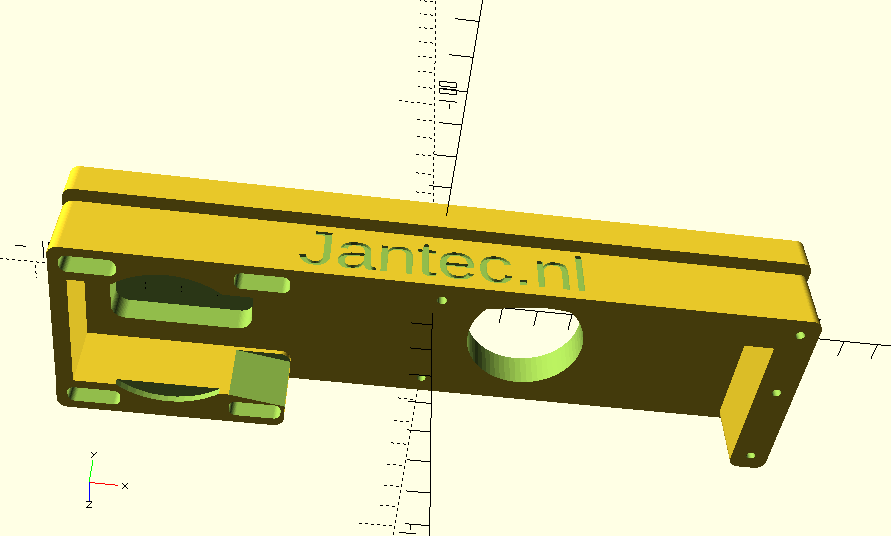
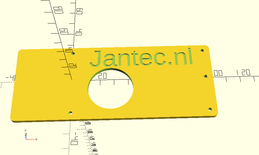
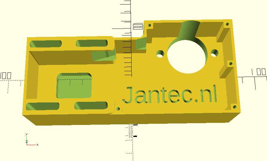
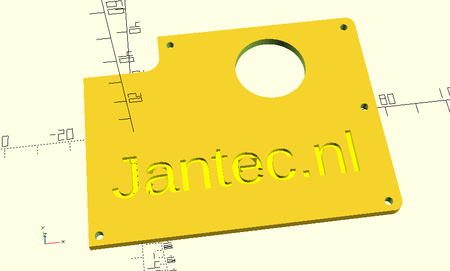
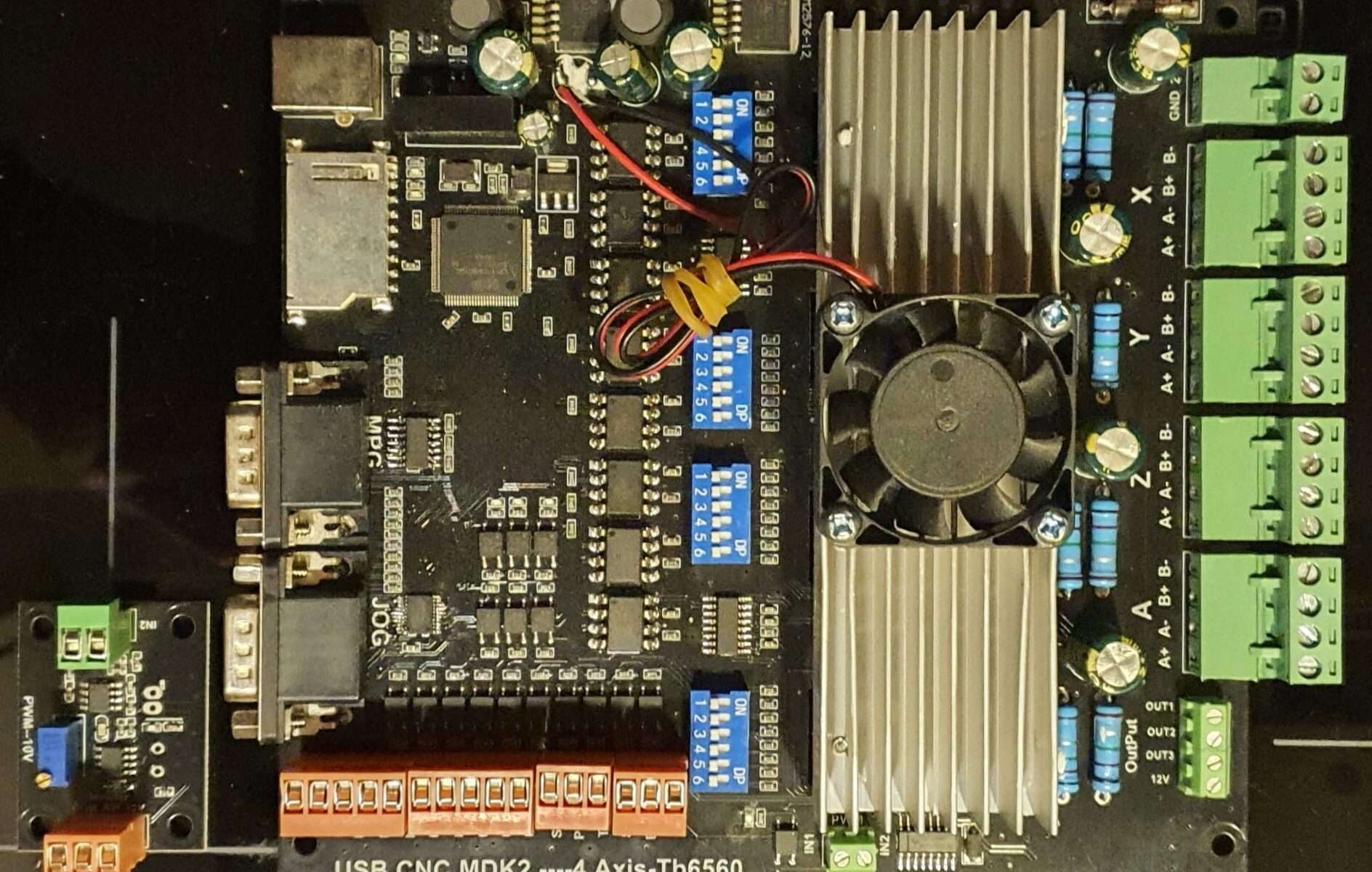
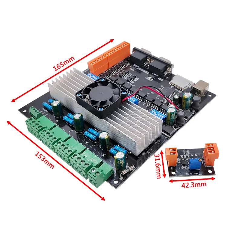
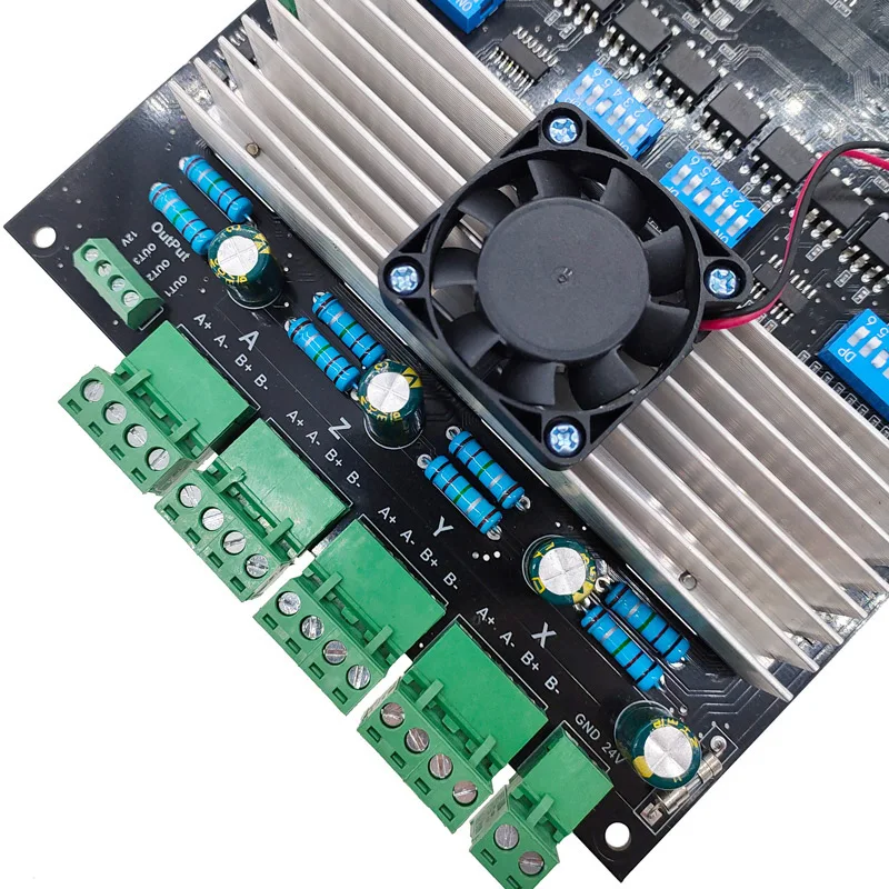
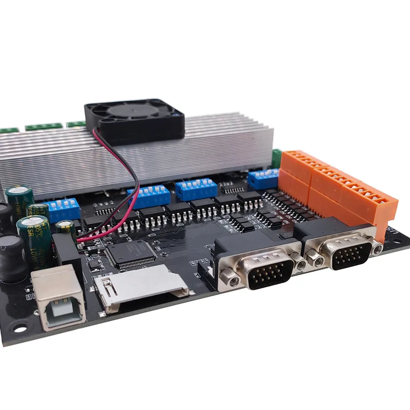
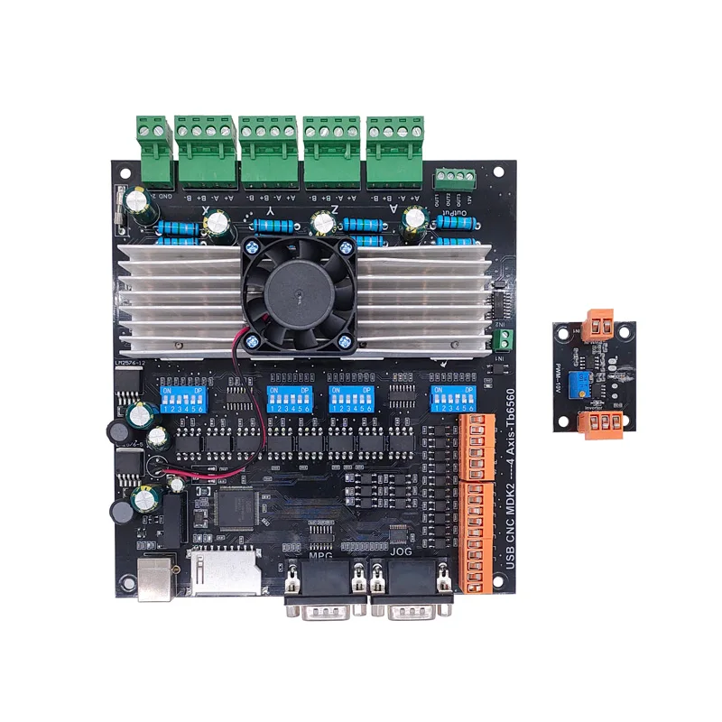
The electronics will become OpenCNC + wifi + wireless controlbox. I received the kit and will put it together the coming weeks.  For now I am going to set the mill up with my all-in one USB-CNC-MDK2 board.  I use this for all of my routers and mills to get it set up in first instance since it is very simple and sturdy. And- you can run it instantaniously without any PC or programming, just with the handwheel or from SD card.  And from the laptop, of course.

GOTO the X axis CNC adapter

GOTO the Y axis CNC adapter

GOTO the Z axis CNC adapter

DOWNLOAD MY CNC ADAPTER DESIGNS  as .STL files

LATEST NEWS:

After this all worked well, I also made designs for  NEMA direct drive adapters on my Toolmania MiniMill:

Direct drive adapter for the X-axis
Direct drive adapter for Y-axis

Above: Direct drive adapter for the Z-axis

left top the Z-axis adapter, right the X axis adapter and at the bottom the Y-axis adapter

What makes it tricky is the choice to make: Will I replace the spindles with ball bearing spindles or not?  Not for the time being, first let’s make everything on CNC and then I’ll see how it performs.

Minimill CNC conversion Toolmania WMD16LV endstops

2021-10-30:  When converting (or upgrading, depends on your P.O.V.) a mill to CNC, it is absolutely necessary to have end stops on all ends. Except the low-end of the Z-axis, an end stop at the Z-axis low end is practically impossible.

On the Z-axis low end another solution has been established by using a Z-stop from the milling toolbit on a fixed X-Y position, OR by testing with the toolbit in place on the matrerial by sight or electronically.

I bought a Z-position sensor for this, which is nothing more than an electrically insulated round pod with a flexible brass top. It is with one wire connected to the Mach3- motherboard as Z-probe and triggers when the tooltip touches the top of the Z pod’s brass top.  Therefore, this trigger is defined as ACTIVE when it is conected to Ground.  Since the mill will be grounded and thus also the tooltip is always connected to ground.  You MUST ground the mill, by the way.  Also for your safety.

Leaves us with the 5 enstops for which I have bought the thinnest available inductive sensors. These are M6 size round and about 8 cm long. These sensors require power, ground and since they are NPN type sensors which means Normally OPEN when NOT active, they will  ground the output pin when activated at reaching the the stop position.  To activate these inductive sensors,  a carbon- containing metal would be best to use and bring the sensor close.  The trigger moment depends on the connected power voltage.  The higher the voltage, the more sensitive the sensor becomes.

I will use 12 Volts or 24 Volts, I will experience a bit with these settings.

NPN and PNP proximity sensors - OMCH

On the net I was unable to find any plug and play sensor holders for my mill, so I developed these holders again from scratch in OpenScad.

Fortunately, I have a lot of starting material in OpenScad from my previous projects.

The X axis left:


The X axis right hand side:


The Y axis front:


The Y axis rear:


The Z-axis top:


Minimill CNC conversion WMD16LV Z-axis adapter for NEMA23 and M3 teethed belt

New stronger version V2 made, also including a top cover 2025,04-24. Will update with pictures after install on the minimill.

MINIMILL_BF16L CNC_Z_adapter belt driven 2025_05_24_V2 Jantec.nl

Please donate $1 to my paypal account if you use (parts of) my developed materials so I can continue to share nice stuff for you to download

:

First working version

The mount on the Z-column needed to get UP so the NEMA23 teethed wheel gets at the same level as the wheel that is mounted on the leadscrew.

Required hardware:

  • 3d printed Z-axis adapter
  • Nema23 stepper 76 mm length with enough torque, 8mm axle diameter
  • 48teeth M3 teethed  wheel of 11mm width, 10mm hole with collar for the leadscrew
  • 24 teeth M3 teethed wheel 11mm width , 8mm hole with collar for the Nema23 stepper motor
  • new M6 40mm length bolts flathead for the top connection to the Z column
  • 4 bolts and nuts M5 to mount the Nema 23 stepper
  • teethed belt 300mm M3 (100 teeth) 9 or 10mm

OR, use the 72 teethed wheel on the leadscrew and get a larger length belt of (I  estimate) 330-350 mm

OR.. another way to mount the Nema23stepper is at the rear of the Z column, BUT I don’t want it to stick out at the rear, that’s why I decided to mount the stepper at the left of the Z-column…

This is the 72 teeth 11 mm width teethed wheel that I will probably use for the final mount at the Z-axes. But not with this bracket at the rear. Unfortunately this bracket does not easily fit at the left or right side of the Z-column. I might make a fitting piece to mount it at the left, though. We’ll see how good the 3d printed parts will perform and if needed the Z-axis will be the easiest to use a standard bracket for mounting the stepper motor as shown above.

GOTO the X axis adapter

GOTO the Y axis adapter

DOWNLOAD THE CNC ADAPTER DESIGNS  as STL

Please donate $1 to my paypal account if you use (parts of) my developed materials so I can continue to share nice stuff for you to download

STL download  for the belt driven adapters of the WMD16LV minimill and Nema23 

Please donate $1 to my paypal account if you use (parts of) my developed materials so I can continue to share nice stuff for you to download

CLICK on the URL to start the download of the corresponding STL file

DOWNLOADS Y-adapter (LEFT SIDE):

MINIMILL_BF16L CNC_Y_adapter belt driven 2023_04_23_V1 Jantec.nl MINIMILL_BF16L CNC_Y_adapter LID belt driven 2023_04_23_V1 Jantec.nl


DOWNLOADS X-adapter (FRONT SIDE):

MINIMILL_BF16L CNC_X_adapter belt driven 2023_04_23_V1 Jantec.nl MINIMILL_BF16L CNC_X_adapter LID belt driven 2023_04_23_V1 Jantec.nl


DOWNLOAD Z-adapter (TOP):

MINIMILL_BF16L CNC_Z_adapter belt driven 2023_04_23_V1 Jantec.nl


GOTO THE MINIMILL PAGE

Minimill CNC conversion WMD16LV X-axis adapter for NEMA23 and M3 teethed belt

NEW VERSION with debree screen:

You can 3dprint the entire bottom and debree screen with the risers for the stepper motor at once, as I did in red ABS at 270 degrees C

For this setup you need

  • 1 piece Nema23 56 length stepper motor with 6.35 mm axis
  • 1  piece 12-teethed M3 wheel with collar, hole dia 6.35 mm, 11 mm width
  • 1  piece 24-teethed M3 wheel with NO collar, hole dia 10 mm, 11 mm width
  • Teethed M3 belt , 9 mm wide and length 255 or 275 mm (need to check this)
  • 3d printed parts
  • M8 rings and nut

Here the connection is shown onto the X-axis/ leadscrew bearing holder with 2 M6 bolts.

And front lid:

And the Milling design for the base plate for CNC machining in aluminium should you prefer this.

The 3D print file for the debree cover and the stepper motor risers, to be placed on the aluminium milled base plate:

GOTO the Y axis adapter

GOTO the Z axis adapter

DOWNLOAD THE CNC ADAPTER DESIGNS  as STL

Please donate $1 to my paypal account if you use (parts of) my developed materials so I can continue to share nice stuff for you to download

Minimill CNC conversion WMD16LV Y-axis 3d printed adapter for NEMA23 and M3 teethed belt

The design for the Y-axis mounting plate for the Nema23 stepper  is shown below and can be 3dprinted or, as I will do after the printed part proves to fit well, CNC it in aluminium on my CNC Indymill router.

The Y-axis adapter proved to be the most difficult design.  It took me 15 trial prints before I got everyting fully optimized.  And I also wanted to have a debree screen with a removable lid, which took some energy to test this.  Also, the belt has to have a clean route where it sits between the wheel.

The physical data for this setup:

  • Nema23 stepper motor
  • 3d printed parts: a: Baseplate inclusing risers for motormount and shield; b: lid
  • Teethed wheel for the Nema23 8mm axle: 10mm wide, 24 teeth M3 with chest
  • Teethed wheel for the leadscrew 10mm axle: 10mm wide: 48 teeth M3 with chest, machined on the teethed inside 9mm depth with a  width of 33 mm diameter to fit the chest of the leadscrew bearing holder
  • The fitting belt is 9mm wide, 300 mm long and has 100 teeth (M3)

GOTO the MiniMill’s X-axis CNC Nema23 mounting plate

GOTO the MiniMill’s Z-axis CNC Nema23 mounting plate

FINAL DESIGN:

Machined the inner part out on the lathe so it will slide for about 9mm over the Y axis’ leadscrew bearing holder

And now the wheel can move over the bearing holder to the right
This saves 9mm mounting space and now the machined handwheel can be replaced, if so desired.  But the handwheel needs to be machined first, to get the dial off.

the small holes can be used to place the lid on the debree screen with small 2.5 mm dia screws  Or, you van leave the lid off and put a wheel on as I have done on the Z-axis.  You must machine the dial off the wheel so it gets thin enough to mount on the remaining M8 leadscrew-end.  A little part of the 10mm shaft will stick out  with my method to keep the handwheel centered.

GOTO the X axis adapter

GOTO the Z axis adapter

DOWNLOAD THE CNC ADAPTER DESIGNS  as STL

Please donate $1 to my paypal account if you use (parts of) my developed materials so I can continue to share nice stuff for you to download

MACH-3 integrated driver board USB-CNC-MDK2

My main supplier of parts is Aliexpress, and I also buy a lot from Banggood.

At Aliexpress, I recently discovered a board that will interact with Mach3 and has onboard drivers for larger stepper motors like Nema23.

This board takes 24 Volts,  has a USB connection to the PC, an SD card slot and 2 x MPEG/control connectors 15-pin/3-row.

I ordered me 1 of these boards to test it on my CNC mill:

Usb Cnc MDK2 4 Axis TB6560 Stepper motor Controller with Mpg Interface 100Khz Driver Breakout Board

I have this tested with Nema23, 24 Volts and the accompanying firm- and software.

It was quite some puzzling to get the drivers installed and I discovered I had to switch off the Windows 10 security feauture that prevents unsigned drivers to be installed.  You can set this off via a procedure which restarts your PC via a series of keyclicks and restart options in the Windows menu. It can all be found on the Internet.  After this, the board worked perfect.

I also bought a handwheel set, which has a male 15 pin VGA connector, as does the board.  I ended up ordering me a female-to-female 15 pin VGA unit from Ale, will see if this works.

The other 15-pin connector (also male) can be used for simple switches to direct all axes up/down or forward/backwards.  I will use this to make auto toggle swtches directly at the machine, next to the Nema steppers.  I have some nice jogging handles that will fit perfect for this.

Also, I bought e a 4th axis unit hat will get connected to this boardon the Minimill.

chicun

4

5

6

Triton junior lathe

I have had my Triton junior lathe for about 10 years +, but actually I have never really done anything with it.  With the machine I have all the gears, a chuck and a set of reversing jaws for the 3-jaw chuck.

Through the USA lathe club I was able to get a CD with all the details of this lathe.  This lathe was for sale around 1935 in all kinds of versions and under all kinds of brands, especially in the USA.  The Sears and Triton brands are the best known.

Under the lathe I attached a motor with a V-belt and in front of the motor I made a forward/reverse switch.

Only recently have I used the lathe a bit and I actually like it very much.  Until now I mostly used my big lathe, but for small work the Triton junior is also very useful.

By now I do have a quick chisel changer on it, a new quick drill bit spanner and a rotating center on the right side in the fixed center, a good set of all kinds of chisels with change plates and so on.

A larger 3/claw is coming, of 125mm.  That comes with a screw/chuck right away.

Some old photos I took right after the purchase in 2008:

Toolmania WBM16LV Mill with X-Y-Z1 en Z2 reading

GO TO MY CNC CONVERSION PAGE

So, after a long search I finally replaced my very old column drill for a small model column mill from Toolmania.  I had the last one still available from this series.

The old drill -)

It is a model WBM-16LV with an indirect belt-driven spindle with a 750 watt vario motor.  Even at low rpm there is still quite a bit of power on the motor.

This model is actually largely a standard model but with a more powerful motor, with a small LCD for the Z-movement of the 50mm Z-handle and with a wider bed.

The working space with this column router is: X:330mm , Y:140mm and Z:180mm

The spindle has MC2 inclusion with a pull/screw of 10mm.  With this, at least a cutter, drill or head will never fall out.

Toolmania’s standard delivery of the WBM16LV, in use with a drill bit in the drill head supplied as standard and a piece of iron in the clamp
With the two screws you adjust the play. Not too tight and just loose enough to turn smoothly without play. Adjustment can always be done later, when needed.

In addition to buying tools, I always notice that you need at least the purchase value of your tools in consumables and additional tools.  No different for the mini mill.  The glass scales, collets, milling cutters, CNC conversion, gas spring, holders for the table, indexer and so on together cost much more than the cost of purchasing the column cutter.

I immediately replaced the standard 1-16mm rack and pinion drill chuck that came with it with a standard 1-13mm manual-open chuck.  But really, I only work with the fixed spindle heads, collets, and the fixed sockets for both milling and drilling.

The associated stuff like an ER-25 collet holder with 15 collets, boring cutter MC2 and so on are from HBM.

You can see nicely here the X-glass ruler, mounted in front of the X-slide. The X transducer is mounted on the Y slide.   On the left below the bed, you can see the Y-axis glass ruler mounted on the base of the mill. To its left (out of sight) is the Y transducer mounted with a bracket to the Y slide.
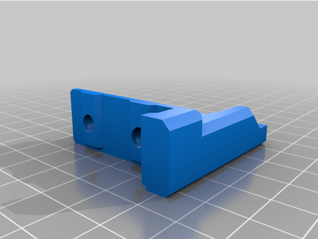
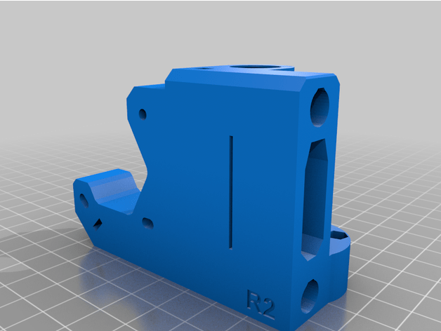
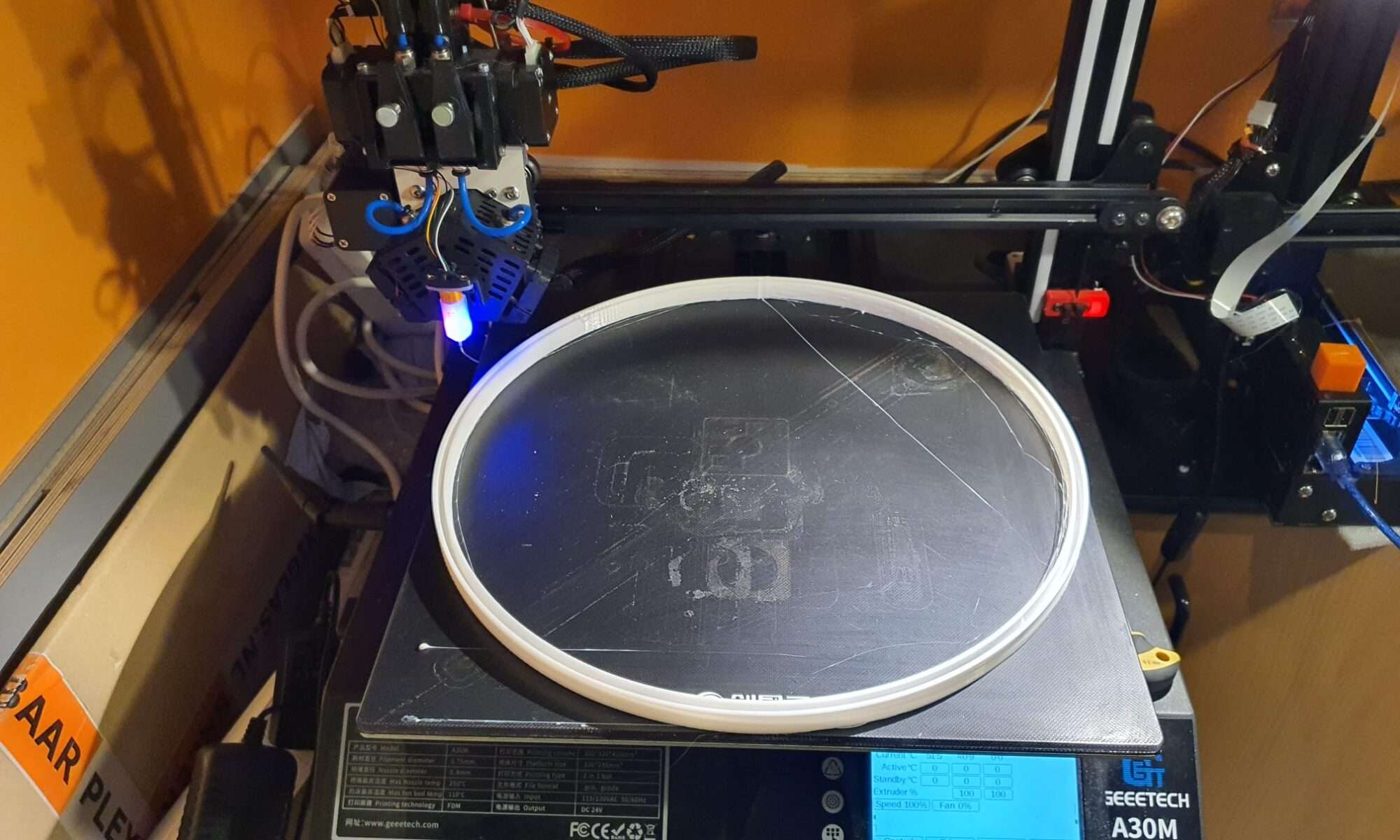
The table has been adjusted for play on the X and Y axes.
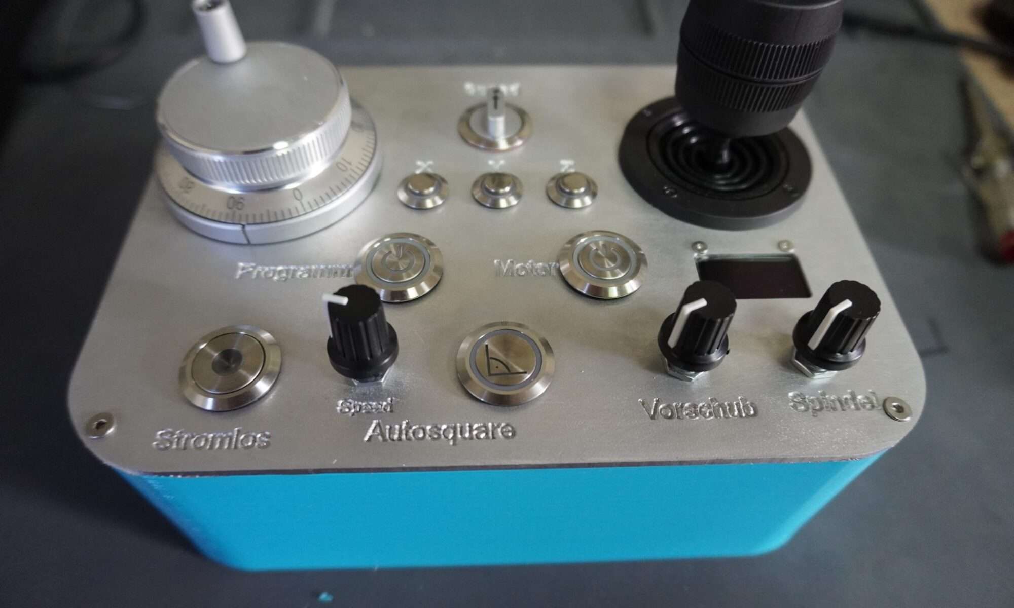
The vertical column has also been adjusted for play, and screwed very tightly again.

Besides the conversion to CNC I have mounted 3 glass scales of respectively 170 (1x) and 370 (2x).  Because my old display module didn’t work with the ordered glass channels I ordered and mounted a matching new module, this one works with an LCD.

The mill with the OLD display module

For converting the column router to CNC, I have already prepared everything and ordered all the stuff I don’t have in stock.

The column router will be used mainly for milling keyways and occasionally some milling work on ball bearing housings and the like.

The column cutter will also be used for drilling and occasionally for aluminum milling, and then a CNC setup is useful.  The CNC setup will be identical to my Indymill.  It will have Nema23 stepper motors with 1:2 belt drive for X and Y and 1:3 drive for the Z axis. I am going to try to merge the handwheels with the gears and then reuse them so that it remains possible to operate manually. The electronics will again be wifi-based with Duet web-based controller and a cloned motherboard from Mellow (FLY) with 2209 stepper drivers.

The limit switches will be inductive: 2 pieces for X, 2 pieces for Y and 1 for Z-top.

The Z-min (or Zero) will be a probe module for the toolbit, which can be put in a fixed place on the table.  It would be nice if the column could be electrically isolated from the spindle so you could really do the zero setting on your workpiece.  I’m still going to figure that out.

For the Z axis, I ordered a 600mm long gas spring, with an operating stroke of 250 millimeters so the column can move more easily.

Examples from others for my CNC conversion:

This will be pretty much my own solution, only I’m using 10mm base plate aluminum. And I’m going for Nema23 motors. The setup will otherwise be identical to this example for X and Y.
Dit wordt mijn Z-setup. Een gasveer om de druk op motor en spindle te verkleinen en een vlakke plaat op de top van de kolom met een rieaandrijving en de Nem23 motor. . Ik ga voor 1:3 (72 tands op de spindle en 24 tands M3 op de steppermotor.). Als het allemaal past komt het handwiel weer bovenop.
Voorbeeld van de basisplaten met 10mm aluminium.

GOTO the X axis CNC adapter

GOTO the Y axis CNC adapter

GOTO the Z axis CNC adapter


Web hosting at home with a DS718+ Synology Web server

The performance of my larger sites left a lot to be desired, and the costs are running up considerably.  I had over 10 sites running, all with the same provider and the costs per site vary between 185 Euros per year and 65 Euros per year.  For the large sites I have 5GB storage and the smallest is 200MB.

HOMESERVER: Previously I hosted a few websites from home, on a Zyxel NAS with a cheap domain provider.  That all worked fine then.  Based on my previous experience I have bought a Synology DS718+ web server, a few fast SSDs with mirroring in it and up to RAM.  The cost is about 800 Euro.  As a backup I have a DS218 play with a couple of big harddisks in it and extra RAM as a normal local NAS with an extra mirrored wordpress server for emergencies and maintenance on the main server.

So now you see this post from my home server.

My experience is that it is always better to be the only one on your own web server than to rent shared hosting, regardless of the so-called SSD hosting et cetera.  That’s what larger companies do as well: Just a fat server on a fast internet connection.

Just to be sure, I do have a backup (UPS) with battery for the 230 Volt power to the internet modem/router and web servers, and a data connection backup via a mobile connection, in case the internet connection goes down. The autonomy of the UPS is about 6 hours.


And… whether I like it?  Actually, I’m mostly very happy with the merging of my various sites into 1 overall site because of its clarity.  Because of my diversity of interests I had just too many sites running which resulted in insufficient attention on the sites.  Now that I only have one,  everything has become much simpler.

That’s it!

OCTOWS2811, Teensy 1.4 & JINX 64×32 LED display

Using an octoWS2811 is the easiest way to make a LED display as shown above.

For this to work properly you will first need to flash a Teensy module with the correct ARDUINO program and .firmware from HERE:

Arduino IDE – Microsoft Store-toepassingen

Install Arduino including the Teensy libraries and then download the firmware (program file for Arduino, this is an example for 8 straight tubes with 32 x WS2812 ) HERE:

Glediatorteensy64x32matrix_with8x32x8

Then connect the Teensy to your PC, check that Ardiuno recognises rthe Teensy and run the driver program to make the Teensy work as WS2812  LCD driver board.

Then, uncouple the Teensy and plug the teensy into the OCTOWS2811 connector module.

In the RJ45 sockets of the OCTOWS2811 module, plug 2 LAN cables and connect the other end to the WS2812 LED modules.

The maximum number of connections to the LED matrices or DIY strings of WS2812’s is 2×4=8 (Octo).

Then, download JINX HERE: jinx

Run JINX directly  (as jinx.exe , no install needed) after you have decompressed the files.

Connect the Teensy with the USB port to your PC/Laptop.

Power your LED matrices to a beefy 5V PSU.

Check yor wiring.

Define your WS2812  setup in JINX (size X*Y, type of direction, zigzag or other, etcetera) so the output will be pre-formatted correctly for your setup.

Start any output and test it.

If not OK, redefine our preformatted setting of the matrix/tubes setup.


DIY windbelt for simple and free energy

A magnet is set into vibration as the wind brings a tightly stretched string or tape into resonance. The magnet is attached to the tape and moves in a coil of copper wire.  The coil is connected to a rectifier and provides energy as the magnet moves back and forth.

That’s the principle of the windbelt.

There have been some initiatives with windbelts around 2010, but you need quite a few of them to make a little energy.  And, of course, it has to be blowing….

Solutions have been made with large numbers of windbelts mounted in windows, in vineyards between fields, and also in areas where there is no electricity at all but the wind does blow.

If you combine a number of windbelts with a solar panel you can make fairly off-grid calls…. -)

Example of a window setup with windbelts:

Example of another DIY kit:

(We can supply this kit on request, we always have 10+ kits on stock)

Other DIY examples:

The theory:

Resonance theory with the famous narrow bridge @ Tacoma narrows that collapsed in 1940 , November 7th, due to the wind :


And another setup of a working windbelt:

Original windbelt by Shawn Frayne (US) Humdinger

With Shawn Frayne’s windbelt, you can generate energy wherever the wind blows.

Even if it’s only a little, you can (slowly) charge your phone with it….

Shawn Frayne patented his invention and made it free of charge for personal use!

After a couple of years, Shawn moved on into other developments.

The use and applications of belt-driven generators for electrical power are rare and seldom used.

The challenge lies in the lifespan of the belt, which must be oscillating to generate power.

For simple applications, mostly a an old VHS tape is used as belt.

If you want to use a larger length of belt, a thicker belt can be used but uit will have to be able to oscillate in the wind easily.

Please read my article about how this works:

DIY windbelt for simple and free energy


Wind Power Revolution _ Eco Wanderer DOWNLOAD

Micro Humdinger by Shawn Frayne, first prototype

From 60 to 83 HP with a DW engine in the Traction Avant 11BN

In the TA I have had 3 engines from 2006:
1) The original TA engine that turned out to be cracked at the corner of the lower block;
2) An ID19P long-stroke lower block that I  assembled with the parts from the original engine such as the overhauled ID11 TA head, TA sump, etc.
3) The final DW long-stroke engine from a donor Citroën ID19 (early DS model 1), including the ID19 head, carburetor, manifold, oil pan and modified (=shortened) crankshaft.
Below I added an overview of all of my engine exchanging photos:


The original TA under block

Below you can see how I used the TA head, oil pan, oil pump, camshaft, pushrods, water pump and so on in option 2) to be able to drive the Traction again with the ID19P engine.

Above you see the first replacement engine that worked in my TA for about 4 years. It is an ID19P engine that fit my Traction without question. I transferred the head from the Traction engine and the camshaft as well.  Unfortunately the oil pressure of this engine was too low to be reliable when the engine was warm.  Probably too much wear. In the picture below you see this block with the TA head on it and with the 3-speed gearbox mounted.  Update 3-2021: After I put the right (SAE30) engine oil in this block, the problem with oil pressure also disappeared completely at warm engine!

With option 3), so the second engine that I bought together with the 4-speed gearbox, a DW engine, the crankshaft had to be shortened because I wanted the vibration damper to come off, see the pictures below:

The DW engine

Above: Crankshaft of the DW engine in the lathe

Above: The right part is already quite turned, the thread is already cut just right of the (to fit back) camshaft gears and the remainder of the right-hand thread can now be cut off.

Above: At the same time the oil pump was overhauled with new gears

And I replaced the aluminium oil pan that was torn during transport with one that I still had lying around. I later repaired this oil pan with aluminum solder [LINK].

Almost ready for the test run, you can also clearly see here that it is not a TA head, just an exhaust manifold on this side.  This block was perfect, both in compression and oil pressure.  Also at hot engine fine!   Underneath this block an aluminum sump pan was placed again so the original oil pump could be mounted again.
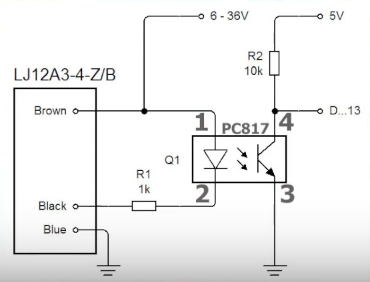
Here you can clearly see why the balance wheel has to come off on a traction avant: The rear engine mount sits on the camshaft distributor cover, that’s going to be a bit tricky to rebuild all that while retaining the balance wheel

DW engine specs:

  • construction years: 3/1963-8/1965
    bore: 78 mm
    stroke: 100 mm
    capacity: 1911 cc
    features: 3 main bearings on crankshaft, slightly convex pistons, balance wheel on timing gear, internal intake manifold, nameplate on carburetor side;
    used carburettors: Weber
    power output declared by Citroen: 83 hp (sae) 61 kW
    fitted in; DS manual, ID Break and ID Export (according to De Serres)
    Citroen ID DW block ready for assembly in Traction Avant 11BN

  •  
    • Citroen ID DW blok gereed voor montage in Traction Avant 11BN
The head of the BW block, with the TA water pump mounted on it. That all just fitted.

Side of the DW block with the sealing plate on the left where the hydraulic pump sits on an ID. The cloth is on the place for the fuel pump.

For comparison the crankshaft of the TA original (top) and the ID BW (right)

ID BW engine with on the left the protrusion that should come off

My solution to reassemble everything correctly: When disassembling, fix it right away!

Volvo V70-II replacing 5-cylinderhead and -gasket

From my V70 5-cylinder with G3 LPG system, 1 valve was burned at purchase in 2015, hence the low price.

The V70-II in 2015 after the cylinder head replacement and other small repairs

The engine light sometimes illuminates, but you can ‘reset’ that according to the seller from Harderwijk (NL).

Also, the side window of the left front door was at the bottom of the door and apparently a window slider had broken off.

But the car was drivable so after the purchase I calmly drove it to my garage at home, parked it in reverse and got to work.

I bought the window guides from aliexpress and the replacement head from an old-fashioned Volvo garage in Westland for 200 Euros.

From the replacement cylinder head I replaced the valve stem rubbers as a precaution and ground all the valves just to be sure.

The head that I took off the car I later also overhauled by cleaning the valve seats, new valves of the first cylinder and new valve seals.

And all valves re-grinded.  That head I sold much later via Marktplaats to a hobbyist with the same LPG problem I had with my LPG car.

Ik heb na de kopvervanging gelijk een klepsmeersysteem gemonteerd, met een controlelampje op het dashboard wanneer de smeervloeistof op is.

Car parked in my garage and ready to start the work!

Below you will find my photos, without further comment but I think everything is pretty self-explanatory.

When reinstalling the head, you have to take very good care of the tappets.

The tappets all have a different size (tappet size) because the valves all end up at a different valve stem height due to wear.

Therefore, you must always measure which tappet should be placed where.  The tappets on my type of car are fixed and not adjustable.

More modern tappets are often hydraulic and self-adjusting, unfortunately this was not the case with my car.  I ended up grinding a few tappets to get to the right value, see the pictures below.

The measurement can only be done by placing and tightening the head, placing the tappets as best as possible, starting with 1 and then 1 more where the camshafts are mounted, pressed and then measure the play and so on.  Quite a job but if you are handy it can be done in 2 hours.

I eventually traded in this beautiful V70-II for an even more beautiful silver-gray C70 D5 automatic, 2nd version from 2006.

That was a fantastic car, both the driving and the experience.  I traded in the C70 after 2 years for a black 2010 V70-III BW F (LPG-G3/ethanol/petrol) with manual transmission.

Fantastically economical with the 4-cylinder Ford Duratec engine, quiet and comfortable.

The C70 was still perfect but I just couldn’t take anything or anyone with me, and that eventually broke me down.

Also, the 160 Euros in road tax per month was on the high side for the C70 diesel while the V70-III on G3 LPG does ‘only’ 100 Euros in road tax per month.

Citroën ID/DS downloads EN

Camshaft characteristics and valve settings Citroën DS21 DX2 types, 1974

Repair manual Citroën for all D types volume 1, December 1974

Repair manual Citroën for all D types volume 2, December 1974

PART 3 manual ID/DS English // Electrical System

PART 4 manual ID/DS English // Bodywork

Wiring Diagram, Cabling, Bulbs and wiring colors Citroën DX DJ DY DT DV from September 1969 onwards

Wiring Diagram only – Citroën DX DJ DY DT DV from September 1969 onwards

3d Printers – overview

At the moment (2025-07) I have the following 3d printers up and running:

  1. Voron 2.4 300x300x300 extremely fast ABS/ASA printer
  2. Voron 2.4 R2 CANBUS_TAP 600x600x500 VERY BIG & FAST ABS  printer
  3. Twotrees Sapphire Pro ‘enclosed’ very fast ABS/ASA printer
  4. Prusa mini very good for PETG primarily
  5. I3 Prusa Bear DIY Fly-CDY-V2 with dual Z axes, 0.6mm nozzle for PLA/ PETG
  6. I3 Prusa Bear ‘plus’ DIY with dual magnetic carriages and sensorless Xhoming
  7. A30M Duet2wifi Geetech dual extruder switchable mono or dual head
  8. Delta G2S Duet2wifi Geetech single head speedprinter 0.8 mm nozzle
  9. Kingroon KP3 mini with full extension package (rails, extruder, firmware..)
  10. Flashforge adventurer 3 all-original almost never used
  11. Ender3pro with TT mini e3 V2.1 , workhorse with 0.6 mm nozzle for PETG
  12. Prusa mini clone (but I can’t tell the difference..) for PETG primarily
  13. E3D Toolchanger met 4xHemera DD’s
  14. Mini Monoprice Delta printer

Prusa mini clone

Volvo V70 F (III/BW) 2010 ethanol/petrol/LPG

I maintain my 2010 V70-III myself, including all (possible) mechanical and electrical issues.

Bought in January 2019, an originally German car (2.0F) with LPG3.

The car was not very well maintained but is in great outer and inner condition.

I checked all fluids, inspected chassis wear and road behaviour, and at inspecting the enine I discovered signs that maintenance has not been done for quite some time.

The car drove well but had hick-ups when accelarating.  These are attributable to the cracked vacuum hoses.

Since no strange sounds were heard I decided to buy the car and I exchanged my silver colored 2006 VolvoC70 (Diesel, automatic gearbox)  against the new 2010 V70.

The C70 was in perfect shape, but I had big problems because I could not take anything / anyone with me in this car.

And- due to Dutch regulations the road tax for the heavy C70 for diesel mounted to almost 200 Euro’s per month…

The V70 on LPG costs me 100 Euro’s per month and LPG is much cheaper than diesel and petrol.

Since I did miss the outside air I had a new Webasto Hollandia 700 glass sunroof installed in the V70 right after purchase and I’m enjoying it a lot!

Winter

Summer


The following has been done:

Maintenance work:

  • New brake discs and -pads all around;
  • New LPG-, oil-, air-, poll-,  filters;
  • New spark plugs;
  • New motoroil and brakefluid (flushed);
  • 2 x New CO sensors;
  • New tyres;
  • New Webasto max. size electrical sunroof;
  • All 8 injectors cleaned;
  • Reset and re-learned LPG installation with Prins interfacre and-software;
  • LED projectors in new bought headlights;
  • Front dashcam and rear top camera, connected to the new head-unit;
  • Parrot installation for better phone performance;
  • Spot painted some small scratches.

Repair work:

  • New throttle body;
  • New coolant inlet on cilinder head;
  • New coolant radiator;
  • After market head unit BLP-950a;
  • New head cover gasket;
  • New vacuum hoses;
  • New vacuum sensors;
  • New spark plugs wiring.

Today: Now, almost 2.5 years after the buy, I am still pleased with the car.  Hardly any oil usage and driven 45.000 km with the car.

Wishes as precaution:

  • New wheel shock dampeners front (Eur 80 each );
  • New wheel shock dampeners rear (Eur  50 each );
  • DONE: New underneath mount for manual transmision Eur 30,
  • (set all mounts is Eur 300);
  • New drive shafts (These appear difficult to get so I might need to get them overhauled or do this myself, since the wheel ends are available as DIY overhaul kit (2 shafts approx. Eur 400, Volvo  orig 2400 Eur for both, DIY overhaul kit is Eur 70 each ).


Throttle body as it was

Coolant in/outlet of the cilinder head, defect sealant holder

sealant ring that has been forced out of the gasket holder

detail of the defective gasket holder

this is the old coolant in/outlet that is connected to the right hand side of the cilinder head

Status at the buy of the car: a lot of broken rubber vacuum hoses that should be connected to the vacuum sensors

After market head unit

blackened air valve

new head unit and parrot display

rear and interior of the upgraded head light unit with LED projector and current-adjusting device

front of the head light unit left hand side (from driver’s perspective) upgraded with LED projector and reworked shroud

Overview of top engine after replacing: The lambda sensors, vacuum sensors, vacuum hoses, spark plugs, cilinder head cover gaskets, spark plugs wiring, coolant connector unit (to cilinder head), all filters, radiator and throttle body

new throttle body

new vacuum sensors and new vacuum hoses (silicon)

new lambda sensors, front one is shown here

FLSTCI Harley-Davidson Heritage softail 2004

My 2004 fuel-injected HD Heritage is all original, except for the tyres. I decided to get Michelin’s instead of the HD whitewall ones, to get better grip during the rainy days..

The Heritage as I drive it presently

And- Next to the original saddle bags, I added an original Road King top case, also full leather.  Top case and saddle bags are easily detachable with original HD detach kits.  I added locks to all 3 cases.

The exhausts are also HD, but not as it came from the factory.  Due to noise regulations in Europe, I installed extra baffles, full-length in both pipes.

And- the original primary frontwheel has been changed to a bit larger so I can drive on the highway with a bit less rev’s.

To get a bit better braking I exchanged the front brake disc for a larger one.

The lights all around are original HD LED.

Original toolbox was also an aftermarket add-on I installed.

I also exchanged the floorboards for a bit less wide ones, due to scraping the originals over the street now and then.  We have quite a lot of roundabouts in The Netherlands and the softail design in combination with my drive style caused unexpected contact between the floorboards and the concrete.  I did get the softail dampers (this 2006 version has 2 in parallel)  at the highest possible position so the rear swing is a lot stiffer and this gave some additional much needed height…

The bike now has 52.000 Km’s on it, and I wil be driving it a bit more the coming years.

Indymill CNC with Estlcam and Arduino Mega

The Estlcam software is a very well working all-in one solution for CNC machines.

The software has the capability to work with many hardware providers of driver boards like f.i. a simple Arduino mega.

BUT- working with add-ons is limited.  The Ramps shield configuration is supported but not with individually homing of any axes.  However, if you let Estlcam program the firmware of the Arduino Mega, everything works out of the box.  BUT-you will need to connect all the wiring directly to the Mega.

In my search for the best working and most simple solution for driving the Indymill, this Estlcam configuration will be tested as well.

I am still searching for a shield that -in combination with Estlcam and an Arduino Mega or Due- will do everything I want/need like inclusion of 6-7 TMC2209 drivers on 24-48 Volts, dual axes  on X and Y,  dual endstops (high and low), mist/flood switches, LED WS2812 steering, emergency switches/power cuts, spindle RPM and on/off control, et cetera.

The MPCNC shield looks promising but there are others available, also.

The Tillboard shield is also nice,  however I am missing some driver positions for my needs.

One of the nice things of Estlcam is that it will also work with all of the parallel and USB CNC boards that are available like all Chinese clones.  I have some laying around and tried these, they all work well providing you will set it up correctly within Estlcam.

I recently (2021-11) bought an OpenCNC h/w kit from Timo Altholtmann (Germany)  that runs on 2 Arduino Mega mini’s  and is controlled by a.o.Estlcam.


Indymill CNC with GRBL Mega256 RAMPS1.4 shield and LCD

This is my test setup for a 1.4 RAMPS shield on top of an Arduino Mega with TMC2209 drivers, optical endstops and individually homing of dual Yaxes PLUS an LCD that shows the exact XYZ locations anytime.

Firstly, I must admit that this option was initially NOT on my list bacause I felt this was a pure hobby-like option.  BUT- as my requirements list grew and other options got less and less, I ordered a Ramps 1.6 shield and plugged one of my Mega2560 boards under it.  Then- the search began to get a working fork of GRBL for arduino that both accomodated the Mega 2560 and my requirements list.  On this list: GRBL, Squaring my gantry, LCD with useful data, Handwheel connection, Preconfigurable buttons on the handwheel (stop, define as zero, probe here, et cetera).  The fork that does this all is: GRBL-Mega-edge.  The last comment is of April, 2020 and the fork was updated last in 2019.  But- it works straight out of the box and the documentation is very well maintained. 

Since it works under the Arduino IDE and has its own library, I foresee little problems in the future.  Everything is freely configurable and it might even be possible to put an Arduino Due in place of the Mega2560 in this setup, with some tweaking of pins and speeds.    And- tweaking is required for the hardware as well. The Ramps boards were never designed for 24 Volts, so this needs to be taken care of.  One might of course use 12 Volts and use external driver modules, but I intend to keep everything very small and make use of an external PSU, and a small handwheel-like box for the Mega2560, Ramps, drivers, LCD, buttons and handwheel knob.  By the way: For getting my designs I already had from my 3d printer background towards the CNC I bought Estlcam (CAM program). This really does a great job at converting it to Gcode and sending it to my Grbl- Mega 2560/RAMPS setup.

Afterthoughts 2021-06-22:  When connecting Estlcam to the Mega2560 and RAMPS1.6 shield, Estlcam can program the RAMPS / Mega2560 configuration, including dual X and Y axis.  This works straight out of the box including endstops. Actually this is easier than first compiling GRBL on RAMPS with Arduino’s compiler.  BUT- it seems that autosquaring does either not work or I did not install Estlcam’s options correctly since the endstops on the dual axis appear to function in parallel instead of indicvidually per axle.

24 Volts connecting is not possible on a RAMPS shield just like that. I removed D1 and powered the Mega2560 with a 9 Volts PSU, and the shield seperately with 24 Volts.  For the Arduino DUE, dedicated RAMPS boards are already available (Smart ramps that compensates for the 3.3 volts in/out Voltage of the Arduino Due)!.

Another option for Estlcam is to program the Mega2560 without RAMPS shield and connect everything directly to the Mega2560 with jumpers.  If this is done, Estlcam will do the bare programming of the Mega and Estlcam can steer almost everything.  Since I bought a license for Estlcam I will, at a later stage, try this as well.  SEE THIS POST


Indymill CNC Nema23 with sensorless homing on Mellow Fly-CDY2

After configuring the reprap Mellow FLY-CDY-V2 motherboard for CNC including the webinterface and installing Mellow’s TMC2209 driver units I got  sensorless homing setup for the Indymill.

It took a lot of time to get it all tuned, as the 3 axes act entirely different due to their different inertia.  The weight that is carried is obviously higher for the Y- than for the X axis.  And the 4 kilogram weighing spindle engine made it pretty difficult to get the Z axis tuned.

The resulting config file is provided in this post.  Use this with caution, since every machine is different, and the used stepper motors, cabling, steppers and PSU all have influence on the CNC’s behaviour and thus on the config settings.

To have the original Mellow FLY TMC2209 drivers work with sensorless homing, set the underneath dip switch to ON

(Diag pin will then be connected).  It took me some time to find out that this is different than other TMC2209 drivers, where the Diag pin is activated by jumper settings on the motherboard.  No idea what happens when you use non-Fly TMC2209’s on the Fly board, but I expect this will not work for sensorless homing.

What I experience on the Y axis is that if you have real problems with homing or skipping steps, the steel Y carriage plates may bend and cause a non-square Y carriage that will never align any more.  I repaired this but preventing is better.

GO TO THE INDYMILL & Reprap Driver POST 

Since this setup with sensorless homing never gave me good speed ratings, I disassembled this setup and continued with endstop setup.  If you want to know how to setup sensorless homing with reprap, please look at my sensorless homing setup on my dual carriage 3d printer, where this works perfect!

Reprap CNC with Mellow FLY-CDY-V2 – Duet2wifi clone

To get the Indymill running, at first I chose to use the Duet2wifi and reprap3 as base. 

Since I am very familiar with Reprap and with the Duet, I want to try this anyway. 

In the end, if it is all installed I need to have software to design and get a file with Gcode and this will be sent to the Duet2wifi controller via wifi, using the Duet’s webinterface that is been developed  for CNC in Beta (DWC for CNC). 

I currently use Openscad for designing, export as .STL and then make a .nc file for the CNC machine from this with Estlcam. 

In Estlcam you can make the machine-specific settings like where the center is, how to set Z=0 et cetera.

The Duet2wifi is my favourite solution because I can if so desired use sensorless homing on any axis.  And- because I need to home 2 independant Y axis and I have a lot of experience in making this work I first went for this solution. For my settings with sensorless homing please see THIS POST 

When you get a good enclosure for the Duet2wifi, use 24 Volt PSU and good driver cooling blocks, you can push the Amps to over 2 Amp continuously.  Works well with my Nema23 steppers.  2.5 Amps is max but we don’t want that,  I found that 1.8 Amps works very well and creates enough torque for the Indymill.  

After having the Indymill work with sensorless homing I rebuilt all to be used with endstops instead for better stability and compatibility with my other driver board setups.  I do want to use the Indymill with several driver setups, and for this setup to be exchangeable, I need the endstops anyhow.  


I am currently using reprap boards from Mellow, since they use the raprap firmware that is ported to the STM core that the Mellow boards use.

On top of this, on the esp you can  mount the Duet’s DWC software and thus also the DWC CNC software. 

I have this currently running on the Indymill with a FLY-CDY V2 board and TMC2209 drivers. 

The nice thing about these Chinese boards is, that you can mount any driver you like, and this means that external drivers is also possible.

So, also the external add-on drivers that do closed loop control can be used.  < I was thinking to make this my additional project: Try to do sensorless homing on the Y axes with this, use very low power and switch off the Closed loop during homing.. If I can get this to work, you will read all about it!>

For the Duet, a setup is available on the Duet website to use an original pendant handwheel unit and add an arduino Pro micro to make a serial interface for connecting to the Duet!  That is a very welcome addition.  See this post!

In the next part of this post my current config file with endstops for Duet/reprap/FLY is shown, as this is operaional for the Indymill.

BE AWARE to use the most current DEVELOPMENT firmware versions for a) the board’s initial firmware, b) the DWC firmware and c) the wifi esp program!

; Configuration file for Board: fly_cdyv2 (STMWiFi)
; Firmware: RepRapFirmware for STM32F4 based Boards 3.3beta1_3 (2021-03-08)
; Duet WiFi Server Version: 1.25-01S-D
; DWC from Sidarius, specificlly redesigned for use with CNC 3-axis
; customized by Jan Griffioen sales@jmwg.nl 2021 04 08
; Made for a CNC Cartesian printer with single X,double Y and single Z steppers and a single spindle with external driver.

; General preferences —————————————————————————————————————-
M453 ; CNC Mode
G90 ; send absolute coordinates
M83 ; and relative extruder moves
M550 PDUET_CNC ; set printer name
M551 Preprap ; Machine password
M552 S1 ; WIFI ON

; Network —————————————————————————————————————————-
M586 P0 S1 ; enable HTTP
M586 P1 S0 ; disable FTP
M586 P2 S0 ; disable Telnet
M552 P0.0.0.0 ; IP address (0.0.0.0 = use DHCP)
M554 P192.168.178.1 ; Gateway
M553 P255.255.255.0 ; Netmask
M555 P2 ; Set output to look like Marlin
M575 P1 S1 B57600 ; comms settings S1 for Original PanelDue and Fysetc 7 inch TFT =OK

; Drives —————————————————————————————————————————-
M569 P0 S1 D2 ; physical drive 0 goes forwards using default driver timings
M569 P1 S1 D2 ; physical drive 1 goes forwards using default driver timings
M569 P2 S1 D2 ; physical drive 2 goes forwards using default driver timings
M569 P3 S1 D2 ; physical drive 3 goes forwards using default driver timings
M584 X0 Y1:2 Z3 ; set drive mapping
M350 X16 Y16:16 Z16 I1 ; configure microstepping with interpolation
M92 X640 Y640:640 Z1600 ; set steps per mm
M566 X500 Y500 Z300 ; Set maximum instantaneous speed changes (mm/min)
M203 X2700 Y1400 Z1000 ; Set maximum speeds (mm/min)
M201 X300 Y300 Z150 ; Set accelerations (mm/s^2)
M906 X1800 Y1800 Z1800 I30 ; set motor currents (mA) and motor idle factor in per cent
M84 S100 ; Set idle timeout

; Axis Limits ————————————————————————————————————————-
M208 X0 Y0 Z0 S1 ; set axis minima
M208 X500 Y480 Z100 S0 ; set axis maxima

; Endstops —————————————————————————————————————————-
M574 X1 S1 P”^xmin” ; configure active-high endstop for low end = LEFT on X via pin xmin
M574 Y1 S1 P”^ymin+^ymax” ; configure active-high endstop for low end = REAR on Y1 and Y2 via pin ymin and ymax
M574 Z2 S1 P”^zmax” ; configure active-high endstop for high end = TOP on Z via pin zmax

; Z-Probe ——————————————————————————————————————————
; a probe must be defined here to have a Z=0 DATUM, including the offset (when there is any, If you use the tip of the tool no offset is required. OR, use manual Z-datum setting via a dedicated macro!

; Mesh G29 —————————————————————————————————————-
;M557 X15:215 Y15:195 S20 ; define mesh grid to be called upon by G29 for an authentic Mesh bed levelling IF this is required and possible

; Fans ———————————————————————————————————————————–
M950 F0 C”fan0″ Q500 ; create fan 0 on pin fan0 and set its frequency
M106 P0 S0.5 H-1 ; set fan 0 value. Thermostatic control is turned off

; Tool definition section; —————————————————————————————————————-

M950 R0 C”!e2heat” L25000 ; Create spindle index 0, with PWM pin on heater 2 output and 25000 RPM achieved at full PWM. At this port, add a PWM-> Voltage 1-10V converter!
M563 P1 S”Spindle 1″ R0 ; Create tool 1 with spindle 0 and call it “Spindle 1”

; Miscellaneous —————————————————————————————————————————-
M140 H-1 ; Disable heated bed
M564 S1 H1 ; Disable jog commands when not homed
M98 P”customconfig.g” ; Execute custom config settings

; Epilogue ———————————————————————————————————————————
;M556 S78 X0 Y0 Z0 ; Axis compensation here if needed
;m98 P/sys/leds_show.g ; Neopixels show (max number is 60)
;m98 P/sys/leds_off.g ; Neopixels OFF (max number is 60)
T0 : select first Tool
M501 ; execute config_override.g

Dometic tropicool TC21FL silenced

Recently I bought us a portable dual power cooler from Tropicool, 21 liters content.  BUT- as I started it up, the noise was a bit more than I expected.

I already own a larger ‘VRIJBUITER’ 38 liters portable freezer/cooler with a  compressor that I silenced last year.

DC mini fridge/cooler - DC-40Y (China Manufacturer) - Refrigerator - Consumer Electronics &amp; Lighting Products - DIYTrade China manufacturers

This 40 liter machine had a 50mm (2 inch) fan to cool the condensor and I completely repositioned some movable parts to get a 120mm (4.8 inch) fan in the machine instead.  The 120 mm fan is a silent fan and this resulted in an almost silent and  better operating freezer/cooler.  But- this machine does not run on the car battery, only on A/C  230 Volts.

So- back to the Dometic machine:  This is the machine

At the front lower  part a large area shows a fan behind the plastic front.  A 12 Volts DC fan is positioned behind this front . The fan is managed by the electronics and only switches on and off. No PWM or similar technique is used.  This cooler is not working with a compressor but with a/some Peltier element(s) and cooling/heating radiators, so a big aluminium block needs to be cooled by the fan to get the machine to work (and cool or warm the inside).  This machine can either cool -25Deg C or warm +25Deg C the inside.  A failsafe mechanism prevents freezing and temperatures above 65 DegC.
The picture below shows the original fan below and the replacement fan above.
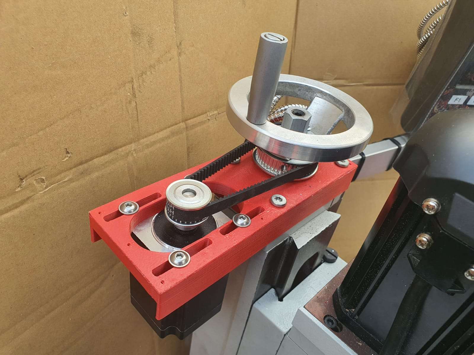
The original fan was IMHO rather loud at 53 dBm (at 50cm distance), I presume mainly due to its design.
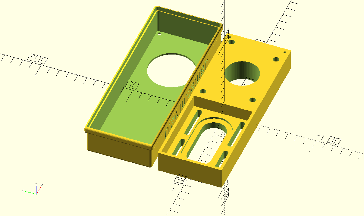
On the net, I read that most users of this machine are pleased with it and don’t think it makes much noise.

But- I need to operate this in our rented place which can either be an apartment, B&B or hotel room during our visits so I want it to make as little noise as possible. The replacement fan is a ball-bearing super-silent PC fan and runs at 12 Volts. 

The replacement was quite easy: Open the lower front by removing all crews around and bottom.  Disconnect the fan-connector from the electronics board.  Unscrew the old fan.  Screw the new fan in place.  Connect the new fan to the electronics board, replace the housing part and screw it back in place.
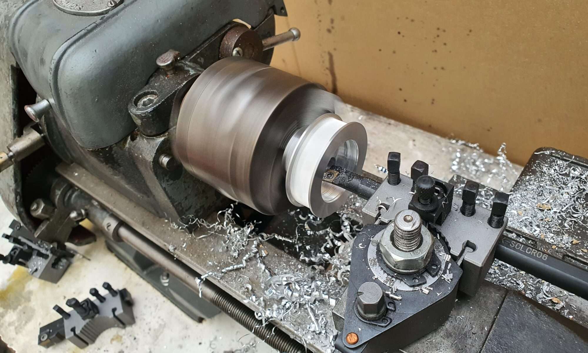
So- the result is that this cooler now actually works a lot more silent, AND a lot better.

I could not get a fixed dBm reading with my portable dB-meter due to the low noise level.

Cooling goes faster than before at about 30% as I measured it in difference in the before- and after situation in cooling to 5 degrees C from room temp of 25 deg C.  Another succesfull project!

We’ll see how we like this cooler during our short stay in France this summer, in Granville!  C) JG 2021-06-30.

Afterthoughts:  To be sure that the cooler is indeed super silent at night, I also put in a DC voltage regulator that can regulate the voltage for the fan between 5 V DC and V max (about 12Volt).
During oiur holiday in France, the machine worked awesome.

In the hotel, we experienced no disturbances from the cooler at all, nore in the car.

And it kept everyrhing cool without too much noise.


CNC pendant for Duet2wifi and Indymill

On the Duet support site a very good description and software for rebuilding a Chinese CNC-pendant for the Duet2wifi is available.

I used this description to program an arduino pro micro, and connect it to the pendant wired, place it inside the pendant and connected the pendant with 4 wires to the Duet.  This works very well.

In the process, I developed some schematics that may be useful to you, available in this post:

Needed: an arduino pro micro and a pendant like this:

China Universal 5V 100PPR CNC 4 Axis Mpg Pendant Handwheel and Emergency Stop F/ Siemens - China CNC Handwheel, Mpg Handwheel


In the above picture, the coloured wires on the inside of the CNC pendant are shown. These wires need to be soldered to the correct pins of the Arduino pro micro (at the right)

Triple mixing hotend for A30M

Next to the penta non-mixing hotend, I recently bought this mixing triple hotend, to experiment with it on the A30M.  It is not the same as the Geeetech original triple mixing hotend, however it does have some resemblance.

Obviously, this hotend requires 3 extruders via bowden tubes.  The extruders I have are all Chinese clones of the 1:3 geared bondtech extruders.

The 3 extruders will be placed on the top horizontal aluminium frame, right where they are originally placed.  In fact, I am rebuilding the machine like the A30M from Geeetech that has a mixing triple hotend.  But- mine will have the Duet2wifi motherboard instead.

Soon as I install this, I will upload pictures and the config files (and all tool files like tfree, etcetera for the three tools as well).


Flightcase for the Indymill’s electronics

Just ordered me a new case for the Indymill’s electronics from Thomann.de.

The idea is to get everything mounted in the cases, and use the control case with the lid open.  The control case gets connected to the Indymill case with multicables and – connectors. When not used, the cables get disconnected from the Indymill and from the control case and go in the Indymill’s case.  The electronics controls will be mounted in the lower part of the control case and the connectors are placed on top of the control panel that gets mounted flush with the  top rails of the bottom part of the controller’s flighcase.  When closed, everything is neatly stored and can be  transported damage-free.

I intend to store the controller case inside the Indymill case, but when moving it around the controller case will be separated from the Indymill case to prevent any possible damage to the mill.

And this is the front I designed for the controller flightcase. Right are the connectors and switches. I can use either the big multiconnector or the standard 4-pol round connectors for increased compatibility with other CNC machines..  The green face is for my Samsung Note10 (8 inch) tablet.

Flightcase for the Indymill

This is only the lower part of the newly built flightcase for the Indymill.  It is 15cm high, 75 cm deep and 80 cm wide, all measured on the inside.

The top of the case is 22 cm high on the inside and it will get perspex windows at the front and top.  Wheels will get mounted at the rear so the case can be moved standing upright.

The Indymill will be mounted in rubbers underneath and on the sides of the frame.  The connectors to the electronics will be mounted in flightcase shells at the front.  When all is positioned correctly and connected, the Indymill will be placed in my garage where I will use it in my large(r) shop.

With the 1.5 Kw spindle I intend to mill aluminium and brass, but mainly aluminium.

1st Job will be to machine ‘flat’ the 8mm aluminium plate I have bought some time ago for the heated bed of my Voron 3d printer. The plate is 310x310mm wide and was not entirely flat when I received it, due to the way it was stamped instead of saw’d.  Now, I will be able to get it done right.  I will use the boring head from my other mill to get this done.  My other mill can only work with smaller objects, not anything as large like the Indymill can handle.


Hanging 3d printer

My last 3d printer I built just produced too much noise, mainly from changing the tools during multi-filament prints

Finally, I made a construction where the printer hangs in big elastic suspenders.  This took away any noise that was previously transferred to the wall, so no more problems with noises throughout the house.  Pfff…

My mini shop

One of the 2nd floor bedrooms was converted into my 3.5×2  meters mini in-house workshop… The garage is used for my larger machines like the lathes, milling- and welding machines, laser cutter et cetera…

Indymill Z-axis with adapted lead screw bearing

The Indymill’s Z-axis uses a lead screw  by design , and not a ballscrew as I would like.  But- that will be changed later.

For now, the lead screw solution will be OK because I will first build the Indymill machine and use the 500 Watt DC engine I already have for my CNC3018 setup.

The leadscrew of the Indymill is an 8mm leadscrew with a brass nut mounted in a 3d printed part that is mounted on the vertical rear of the Z-plate.

And- the drive stepper motor is mounted hanging on a horizontal plate on top of the Z-plate.

The required motion is exchanged to the leadscrew with a pair of 8x10x22  treehed wheels that are coupled with a GT2-10 mm wide 200 mm long belt.

The change I made to the original setup is to use an original 8mm lead screw bearing on top, under the horizontal plate.

I did not particularly like the original setup with an 8mm bearing in a 3d printed holder, and an 8 mm lockup ring under and above this bearing.

I had to machine the pro-bearing to fit the Indymill’s mounting holes and get  the threaded drive screw nicely centered.


Indymill adapted X-axis for more rigidity

2021-05-22

On top you see the X-axis, still without mounted linear rails but the 1605 screw is loosely mounted. The red connecting piece for the Z-axis is on the ball bearing nut. the black part on the left between the 2 lengths of 2040 aluminium extrusions is the (anti-) push/pull bearing block that holds an axial (up/down/left/right) and a radial (left/right) bearing but can not withstand any real big lateral force (L-R)

Under construction-still trying to find out how to do this.

I intend to use the same method as with the Y-axes so drop the 3d printed parts as much as possible and re-use the available bearing blocks and nut holder.

For the red nut holder I only need to make a flat extension plate to connect the nut holder to the Z-plate.

For the end bearing block BF12 to the right, this is no problem. I can mount it easily on the sideplate’s outside.

The push/pull bearing block BK12 is more difficult to re-use,  I will try and find a small enough connection block that is 3d printable to shape the BK12 in, and still fits in between the 2 horizontal aluminium profiles that shape the X-axis. It will be very tight so I might have to make something myself, possibly I will just mount the BK12 on a in-between piece of  2040 and first I can mill a hole in the center of the 2040 piece so the end of the 1605 ball bearing screw can gain access to the BK12… Or something like this, will try and report how it goes later!

2021-5-24: Found a possible solution with an adaption of the same  Nema23 to BK12 housing as is used for the Y axis. I am printing this fast with PLA on the Ender pro, will cut off some flesh of the NEMA23 top and bottom flange and will then fit this between the 2 lengths of 2040 extrusions and see how it works!  The screw holes will have to be saved, but 4cm in the center will be removed, some 4 mm wide om both top and bottom.

Today I made the last solution fit the X axis and got all related components to fit the X-axis.  During this I found that the left bottom ball bearing slider cannot move along the BK12 block..  So, I machined some material from this block’s side bottom.  That doesn’t hurt but it does impact my planning a bit.  And- during the process I destroyed a piece of the PETG BK12 holder that connects the BK12 bearing block to the stepper motor and the in-between side plate.  I already directly printed a new ABS part to replace the PETG and wished I had started with ABS like I dit with the Y-axes.  But- look at the bright side: Now all 3d printed parts will be ABS red: like the steel plates!

You must know that I elaborated quite a lot on how to print the Neam to BK12 couplers and fount that it is not good to print these withh the face to the Nema23 motor DOWN.  Instead- I printed them flat, with the side that faces the stepper motor to any side but down or up.  This gives great strength to the 2 pieces that carry the mounting holes for the BK12 bearing so they won’t break during use.

And I found that ABS in my case (both ABS red and PETG vblack are Sunlu products)    works better for this build because the PEG breaks under strain and ABS flexes a little but does nor break..


Indymill adapted frame and -Y-axes build instructions

In this post, you can see how I changed the original Indymill to more rigidity by using the original 1605 aluminium nut holders for the 1605 ball bearing screws of the Y axis, and how I made use of the BK12 and BF12 ball bearing blocks instead of the 3d printed parts like in the original build.

Yesterday 2021 05 22 I cut the aluminium profiles that are required for the frame of the Indymill.  My metalsaw is set at the perfect 90 degrees angle that you need for these aluminium extrusions

Today I put the frame parts together, based on the changes that I made to the ball screw holder block and to the screw bearings and -holders. And- overnight I spraypainted all metal parts red.  Used just what was lying around.

Left side, left is the Nema23 motor, and the BK12 bearing block is now connected to the engine plate with an ABS sideways printed connecting piece. ( I found the PETG printed parts I made earlier to break on the sleeve at the left when applying force, so I went for ABS and I printed it as you see here with supports to give strenghth for the bolts and nuts.) To the right, the aluminium nut holder is placed. This has been milled down and new screw holes were made in the holder and plate to connect it to the plate (see the text later in this post)

same treatment on the right hand side

Overview of the RH side with the end bearing and -block, connected to the front plate bearing holder. I milled additional holes in the bearing blocks (front L&R) to (re-) use the tapped M5 holes that are already in the red connecting plate

When building the frame, make sure that you do not initially screw anything tight.  Follow the steps that apply to any build:

  1. Make the footprint square by measuring either with a good 90 degrees angled measuring hook OR measure the diagonals against each other and make them alike.  Then, tighten all corner screws .
  2. Re-measure the footprint’s left against right length and also front/rear length. If there is any difference here,  a) take everything apart and b) make sure you have equal sizes for your build where this is required.  OR, if you have a non-standard build, make sure you build according to specs sizes. The, do 1. again.
  3. For a lineair rail: use a ruler that is specifically made for your type of rail  You can 3d print one or buy two aluminium ones.  ALWAYS use at least 2 rulers!  With the rulers in place at 20% from left and 20% from the right,  after you have installed the rail loosely with the screw in the nuts, tighten the screw a bit but not too stiff..  We will get back to these screws at a later stage.
  4. Put the connecting piece on the motor’s axle (8mm side) and tighten this well.  Preferably, use some loctite on the axle but don’t overdo it.  Be aware that you need to testfit the BK12 first.  make sure that the connecting piece almost touches the BK12’s nut!
  5. Put the stepper motor and the BK12 connector together, using the 3d printed thin NEMA23 adapter plate between motor and steel plate. Do not yet tighten this too much.
  6. Make an original aluminium 1605 nut holder block shorter to fit exactly.  See the picture.
  7. Fit the aluminium nut holder block including the entire assembly of the 600 mm long 1605 ball bearing screw on the machine, and superglue the block in the correct position.  Let it dry so it won/t come off. Demount verything except the steel sideplate and the glued aluminium nut holder.
  8. clamp the nut holder to the steel plate with a grip vice, just to make sure it all keeps together.
  9. Drill 3 new 4mm holes through the steel plate’s lower part ,  drill through the aluminium block as far as possible.  2 holes on the lower side and 1 just between 2 of the top 3 holes,  NOT where the existing hole of the aluminium nut holder block exists.
  10. Get the nut holder block loose, if it has not already come off.
  11. Tap M5 in the holes of the nut holder block.  You will have come through the big center hole (for the nut) with 2 holes, make sure this gets cleaned up on the inside.
  12. Drill the new holes in the sideplates with 5.5 mm drill (to give you mounting clearance)
  13. Place the sideplate on the 2 bearing blocks of the linear rail with 4 outer M3 x8 (or x10) screws.
  14. Put everything loosely together
  15. Mill an end baring block to fit the 1605 ‘s screw end at the front an mount this at the exact center of the small front plate.
  16. Now, connect your nema 23 engine to a motor steering device so you can test the setup.  First, turn the screw by hand and it should run smooth.
  17. Since you want to have an even height of the side plates, do not alter these unless it needs to be done on both sides equally.
  18. Your fixation point is the only non-movable position, at the rear of the frame.
  19. Move the carriage to the rear and now, see if you have slack on the M3 screws of the slide bearings AND on of the 3x M5 screw the rear of the aluminium nut holder. If so, first tighten the M3 screws.  Then tighten the M5 screws.  If not, loosen ALL of the linear rails screws ans move the rail a little. If this is possible, tighten the M3 screws of the linear rail’s bearing blocks.  Then, try to get as much clearance on the linear rail’s movement up/down as you can and tighten the 3x M5 screws of the nut holder block.
  20. Now, tighten 1 screw only of the linear rail, at the position above the nut holder.
  21. Move the carriage entirely forward position.
  22. Tighten the linear rail’s M3 screw that is exactly in position above the nut holder (of the ball bearing screw)
  23. Now, tighten all screws of the linear rail.
  24. You’re done!
  25. Check the other side and if the linear rail’s height differs from the other side,  the only thing to do is to start over again, where your slack is in the 5.5 mm holes of the steel plate’s screw holes for the  nut block.  If you play with this, and then adjust the linear rail’s height, you can get it all even.  At least’eventually I got mine right but it took some time.  Have fun!

Things to bear in mind: You don’t want anything out of parallel like a linear rail that is uneven to the aluminium profile on which it is mounted or a ball bearing screw that gets under tension.  There is also another way to see what is happening while you are tweaking the hardware/frame: take the front bearing off and see what happens to the end of your ball bearing screw in the hole up front when you move the carriage.  It can tell you much about what is happening…  It should always stay perfectly centered but I’ve seen it up, down and all other directions.. -)

After making the base frame and the Y axes, the rest is more simple. Just get the 2040 pieces in place, I started with only the lower one. The put all in like the rails, the ball bearin screw bearings, the ball bearing screw, coupler between screw an motor, the stepper motor and the X axis is done.

After the X axis, the Z axis is placed in. First put the rear plate on the 4 linear rail sliders and mount the ball crew block of the X axis to the rear. Then, put the vertical short MGN12 rails on the rear Z plate. Then put the bearing for the leadscrew on the top plate’s undernetah.  Put the corner pieces on the top plate and mount it on top of the rear Z plate. Then, feed the threaded rod through the top bearing, mount the angine an d teethed wheels and feed the screw through the nut…  Are you still with me?

Top view to get it more visble: engine and leadscrew connected with teethed belt

I decided to put 3 connecting pieces between the frame’s left and right Y axes to maintain stability and rigidity. After I put these in, the frame was very square and stabele, but also heavier..)


Last time that you see the frame without any wire. Next I will get the endswitches on the farme, the spindle and all other parts that are required to get my Indymill up and running! BTW I mounted 4 heavy purpose rubber feet under the frame, just to prevent having any tordoial stress to the frame when I put the frame anywhere to be used.

And- I must say, this build goes quite well. The materials are OK, and the guideline from the build description was very good. Although I never use it anymore.  The build is quite self-explanatory once you start building the Indymill CNC machine.  I also cahnged quite some parts, and made alterations where I felt this would improve the machine to fit my purpose better.


Milling the Indymill parts

My very basic mill is just an old drill machine with a large X-Y cross table mounted underneath. But- for basic milling it works.

In the process of change: My HBM25 lathe is going to be changed (temporarily) to act as mill. I need some parts milled flat and square, this will do that. Waiting for the MK4 sleeve for my MK3 milling head…

All mounted to the lathe

Indymill iron hardware treatment

The required iron plates were not available in ready- to use state at the time I needed this, fortunately I could buy the plates as a kit with all of the drilled holes already in it, non-painted.  And- all of the thread tapping still needed to be done.   Since I am also making changes to the design of the millling machine,  some holes will be altered and this is best done when the plates are not yet painted.

The raw streel for the Indymill.  I put small colored circles  where the thread needs to be tapped.

Rustpreventing primer spray-painted the Indymill’s iron plates