Skip to content
Jantec.nl

Jantec.nl

3D modeling, scanning and printing

  • Technology
    • 3D printing
      • 3d Printers – overview
      • OCTOPI
      • Mellow Motherboard
        • Mellow FLY-CDY-V2
        • FLY CDY V2 Download
      • Cartesian
        • A30M
          • Original
          • Duet2wifi
          • Penta extruder
        • Ender 3
          • Original
          • MMU2S & SKR mini E3
        • Prusa I3
          • Prusa I3 clone
          • Prusa Bear
          • independant Z-axis
        • Dual carriage I3
        • Dual carriage I3 Config files
        • Flashforge Adventurer 3
        • Prusa mini
        • Prusa mini clone
        • Kingroon KP3
      • Core-XY
        • E3D toolchanger
        • Voron
          • Voron 2.4 Core XY build
          • VORON DUET2WIFI
        • Twotrees Sapphire Pro
      • Delta
        • 2GSpro Delta
        • Delta Duet2wifi
      • Are professional 3d printers overpriced?
    • Arduino
      • Xmas star
      • Arduino led bar
      • Circular clock
      • LED WS2812 BIG panels
    • Toolmania WBM-16LV Mill
    • Minimill CNC conversion
      • X-axis direct drive
      • Y-axis direct drive
      • Z-axis direct drive
      • X-axis teethed belt
      • Y-axis teethed belt
      • Z-axis teethed belt
      • Endstops
      • CNC integrated driver board
    • IndyMill CNC router
      • IndyMill CNC machine
      • FLY-CDY-V2
      • Cabling
      • Estlcam and Arduino Mega
      • GT2560 GRBL
      • Mega256 RAMPS1.4
      • Nema23 sensorless homing
      • CNC pendant for Duet2wifi
      • Flightcase for electronics
      • Flightcase for the Indymill
      • CNC Controller final choice
      • Z-axis lead screw bearing
      • Adapted X-axis
    • K40 lasercutter
  • Mobility
    • BYD Atto 3 EV 2022
      • User experiences
      • Spare tire in the trunk
      • Blog
      • Delivered 2022-11-14th!
      • User experiences
      • Under the bonnet
      • All-weather tires
      • Charging across public pavement
      • Tow bar
      • Ordered 2022-10-22th (NL)
    • Traction Avant 1955
      • Blog
      • Pending changes
      • Executed changes
        • Electronic ignition
        • 6V to 12Volts
        • Traction Avant 4 gears
        • From 60 to 83 HP
        • GPL in my TA
        • New driveshafts
        • DOT3 brake fluid
        • Clayton heater
      • Repair and maintenance
        • Starter motor repair
        • Picking up the car
        • 3 Speed gearbox repair
        • First MOT (2006)
    • FLSTCI HD Heritage 2004
    • Volvo V70 F (III/BW, SOLD)
    • V70II (SOLD)
      • Volvo V70-II replacing 5-cylinderhead and -gasket
  • Other projects
    • Dometic tropicool TC21FL silenced
    • Mellow FLY-CDY-V2 motherboard
    • Soldering aluminum
    • DOT3 or DOT4 BRAKE FLUID
    • Plasma cutter router DIY ‘the simple way’
    • Wobbling in cheap linear bearing screws
    • Photography
      • Mamiya RZ67
        • RZ67 camera setup
        • Digital back experiences
        • Cocking shutter repair
        • Bellow replacement
        • Shutter release repair
      • Lomography
  • New
  • Downloads
  • Privacy Policy
  • DUTCH SITE

My 1955 Citroën Traction Avant BN blog

Posted on 30 June 20235 July 2023

Converting HI8 videotapes to digital video at high quality from Firewire DV to Thunderbolt 2 or Thunderbolt 3 USB-C

I had a lot of old HI8 tapes that needed converting to digital media, preferably with high quality.

I tried several methods, including the old fashioned analogue recording machines like the Philips that utilized an HDD for analogue TV recording.  These machine was also equipped with a DVD recording capability BUT this never really gave satisfactory results, regarding the video quality.

Standalone analogue video converters to USB also never gave me good results.

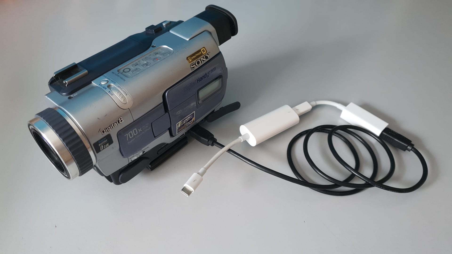
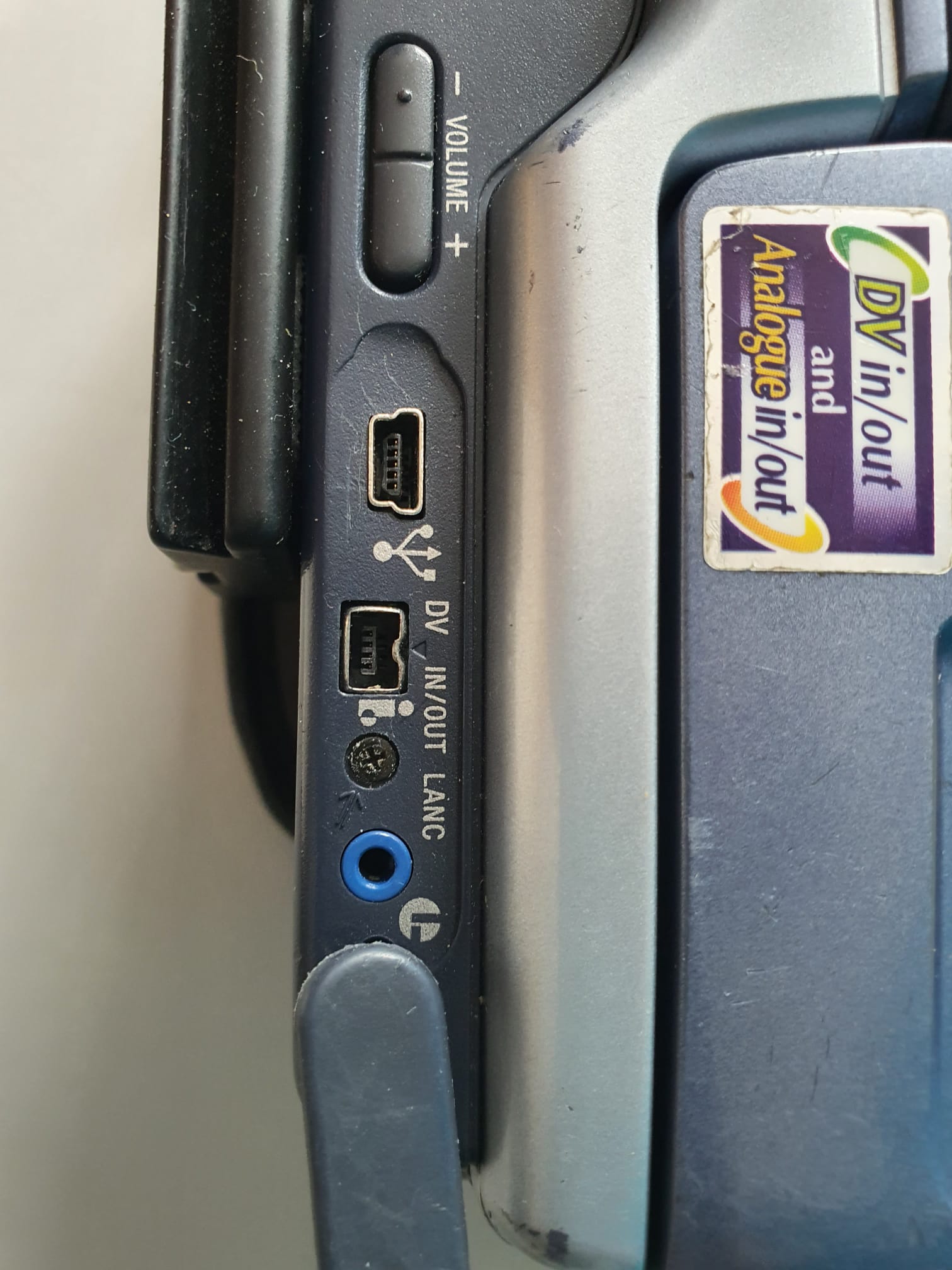
After a lot of research I identified a way to generate digital video from a specific type of Hi8 camera with DV output, and convert this with a specific set of apple converters to Thunderbolt 2 (or 3 or 4 USB-C).

The setup for connecting to any Thunderbolt 2-and UP PC or Mac or iPad looks like this:

The hardware setup is as follows:

Sony DCR 1 HV 330 Hi8 camcorder with mini DV firewire in/output:

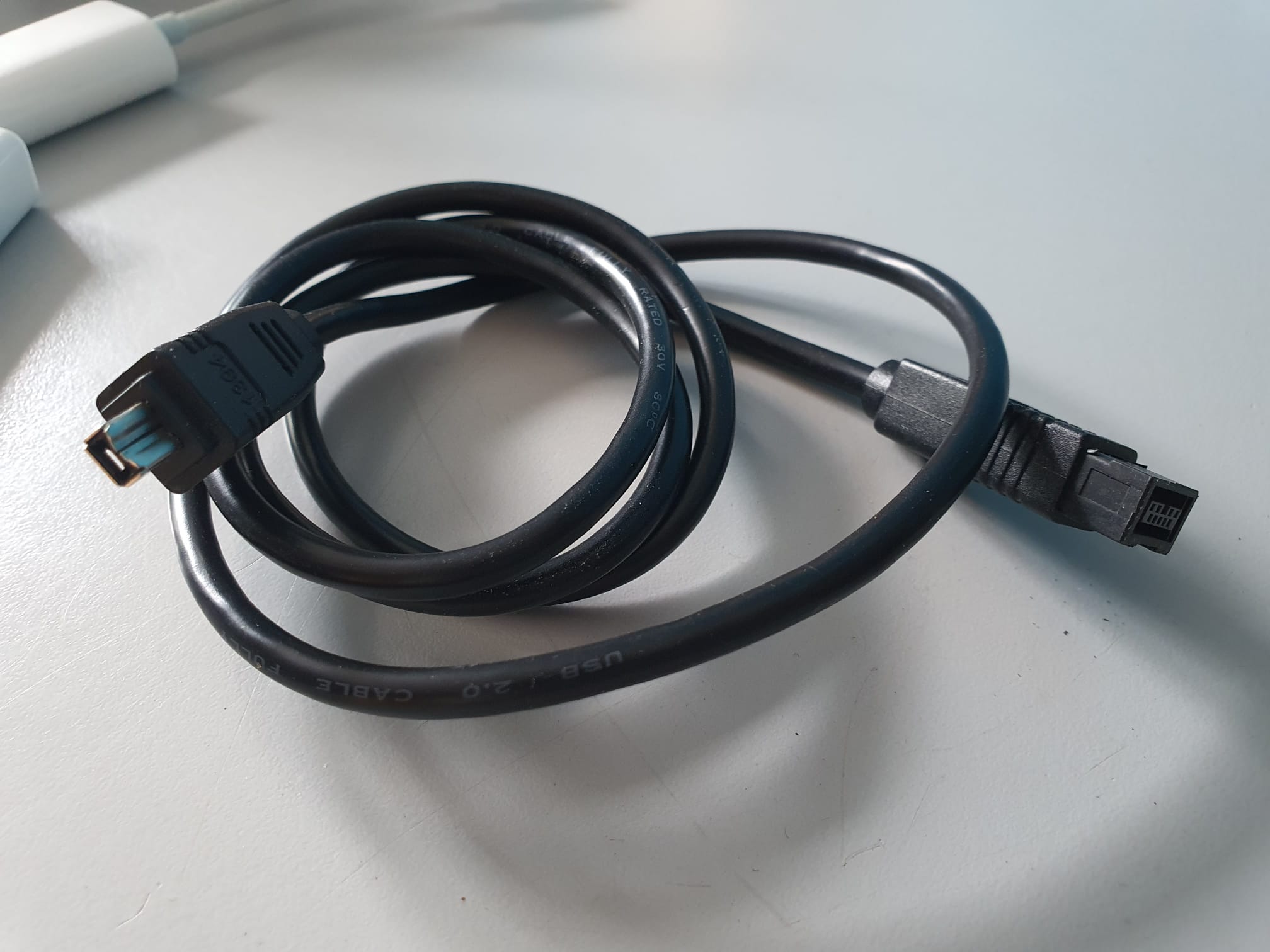
Firewire 400/800 cable from mini 6-pins  to Firewire  ‘standard’ 9-pins

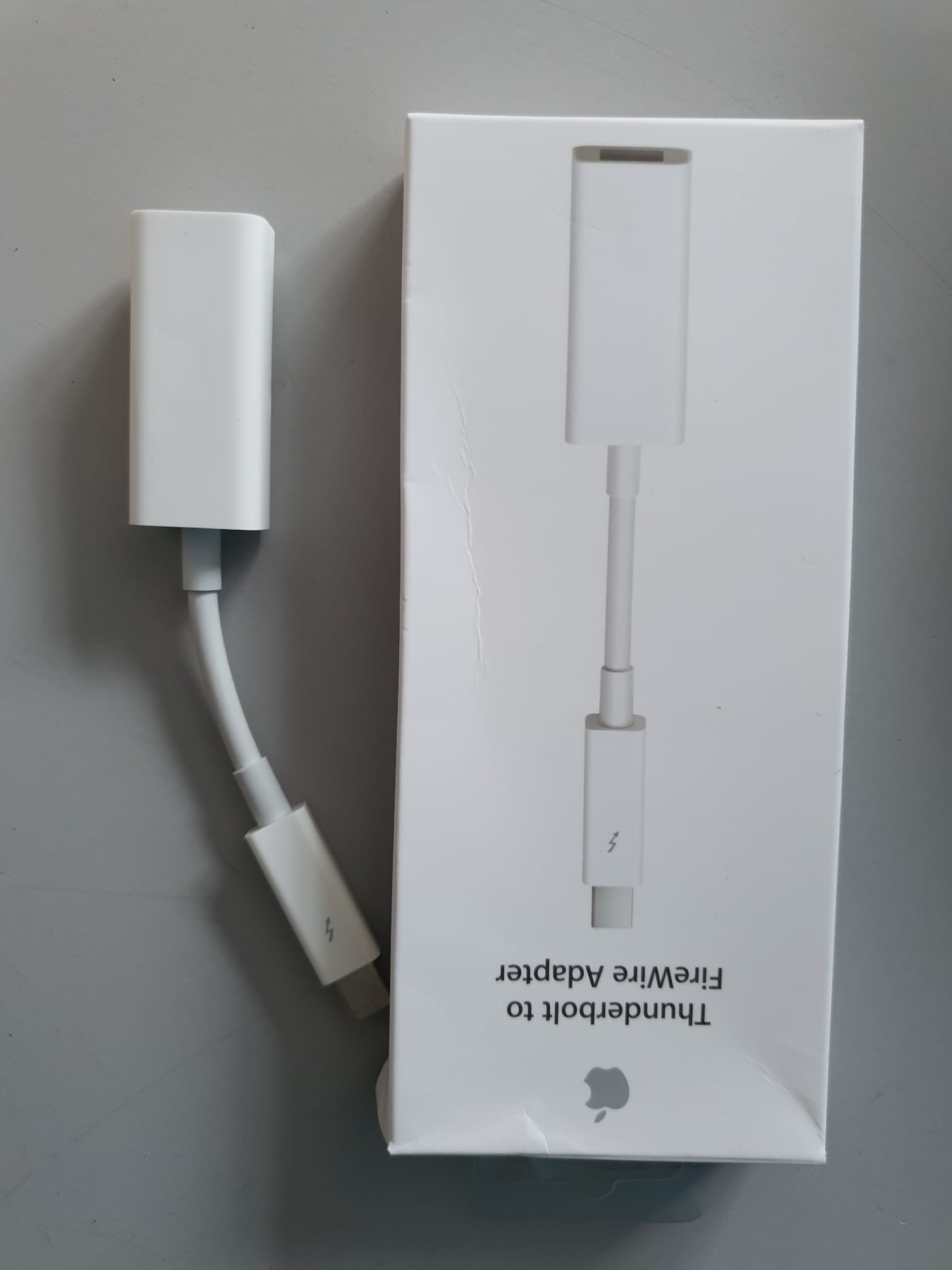
Firewire 800 (9-pins)  to Thunderbolt 2 (Apple) converter

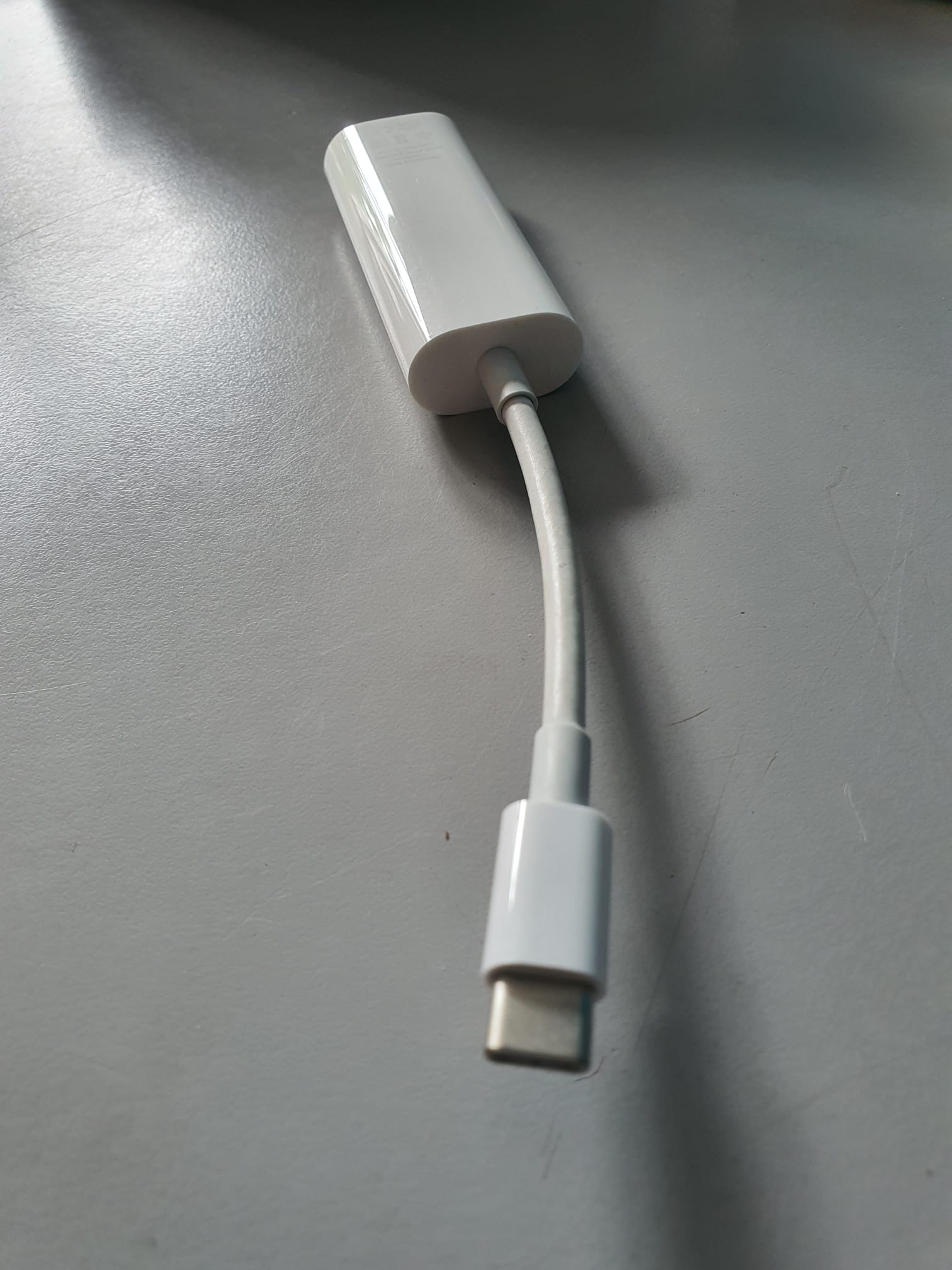
Thunderbolt 2 to Thunderbolt 3 (=USB-C) (Apple) converter nr.  A1790

If you have a PC, you could also just buy a cheap PC-card with firewire 800 (9-pins), then you only need the Firewire 400-800 cable to connect the DV camera to the PC’s firewire card.

For importing the video, I used a software program that I bought online for my recent Dell XPS13 laptop which worked very well.

For importing the video stream you can also just use VLC mediaplayer, using the streaming option. Just set the storage in VLC to save the streamed video!

That’s it!

C) Jantec.nl 2023-6-30

Posted on 28 May 202313 October 2025

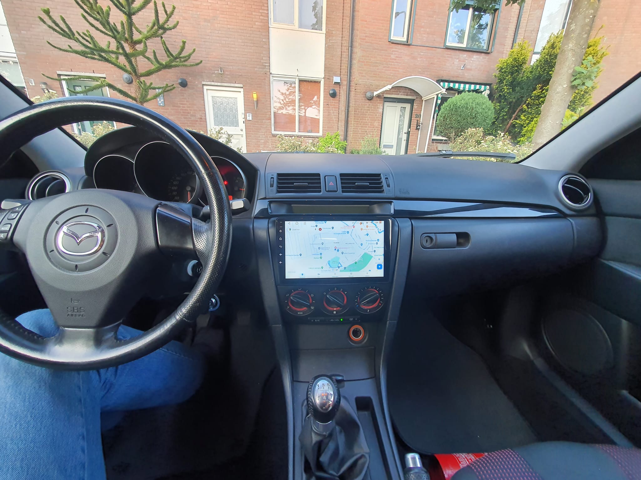
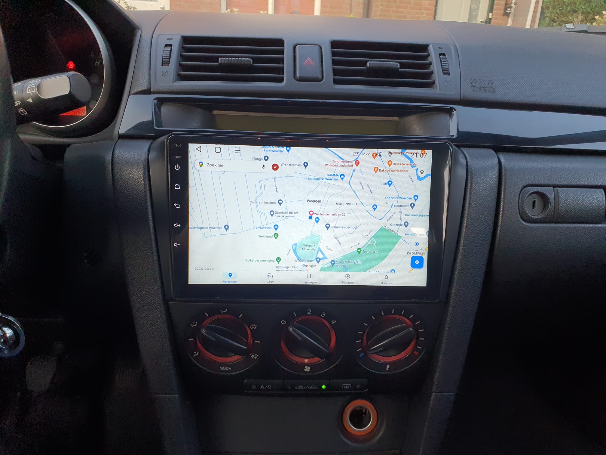
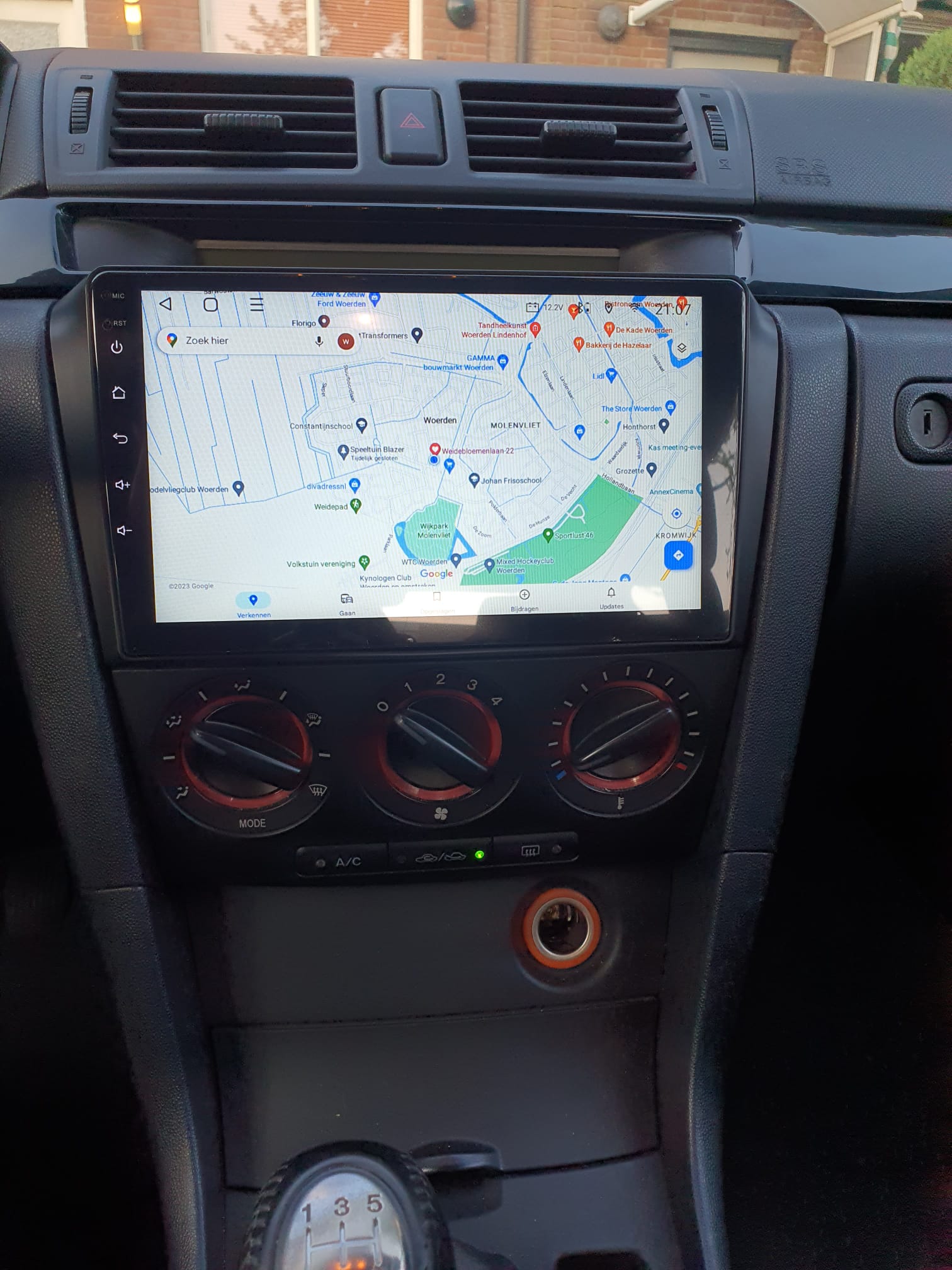
Mazda 3 (2004) Android 11, 10 inch head unit with Steering Wheel Controls SWC

Just (2023-5-28) got the new Android 11 CARPLAY head unit installed in our red Mazda 3 //  1.3 BK(2004).

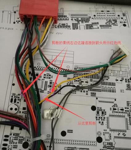
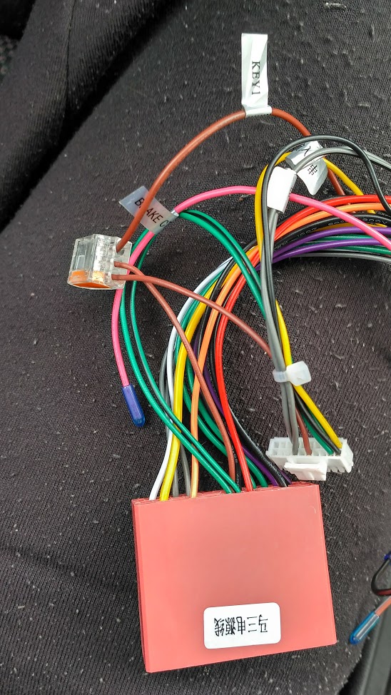
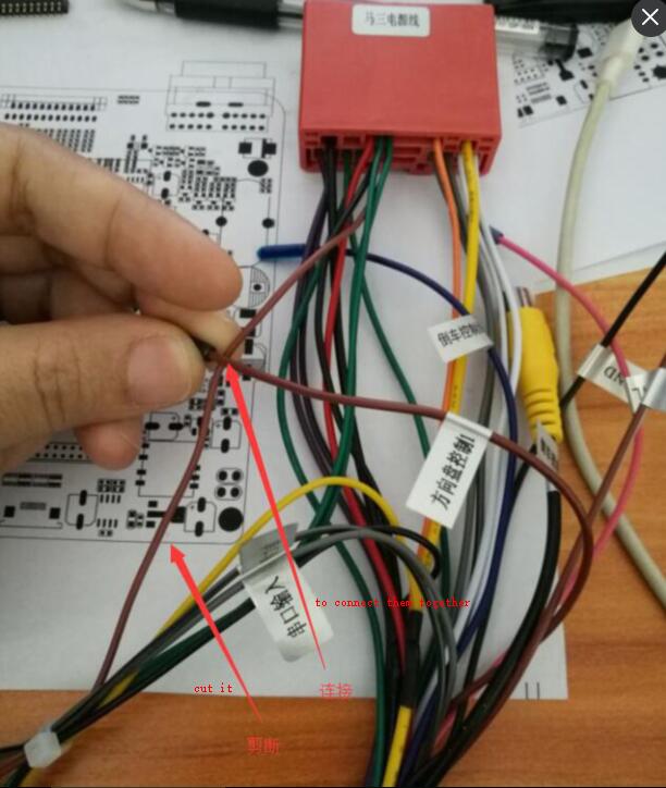
All went very easy, except the Steering wheel controls.  Turned out I had to cut the delivered control connectrion for SWC2 that went into the OBD control module and reconnect this directly between the head unit and the Mazda’s big connector.  Just like with our previous Android 6 head unit, which in the end got so slow that we decided to toss it for a new one.

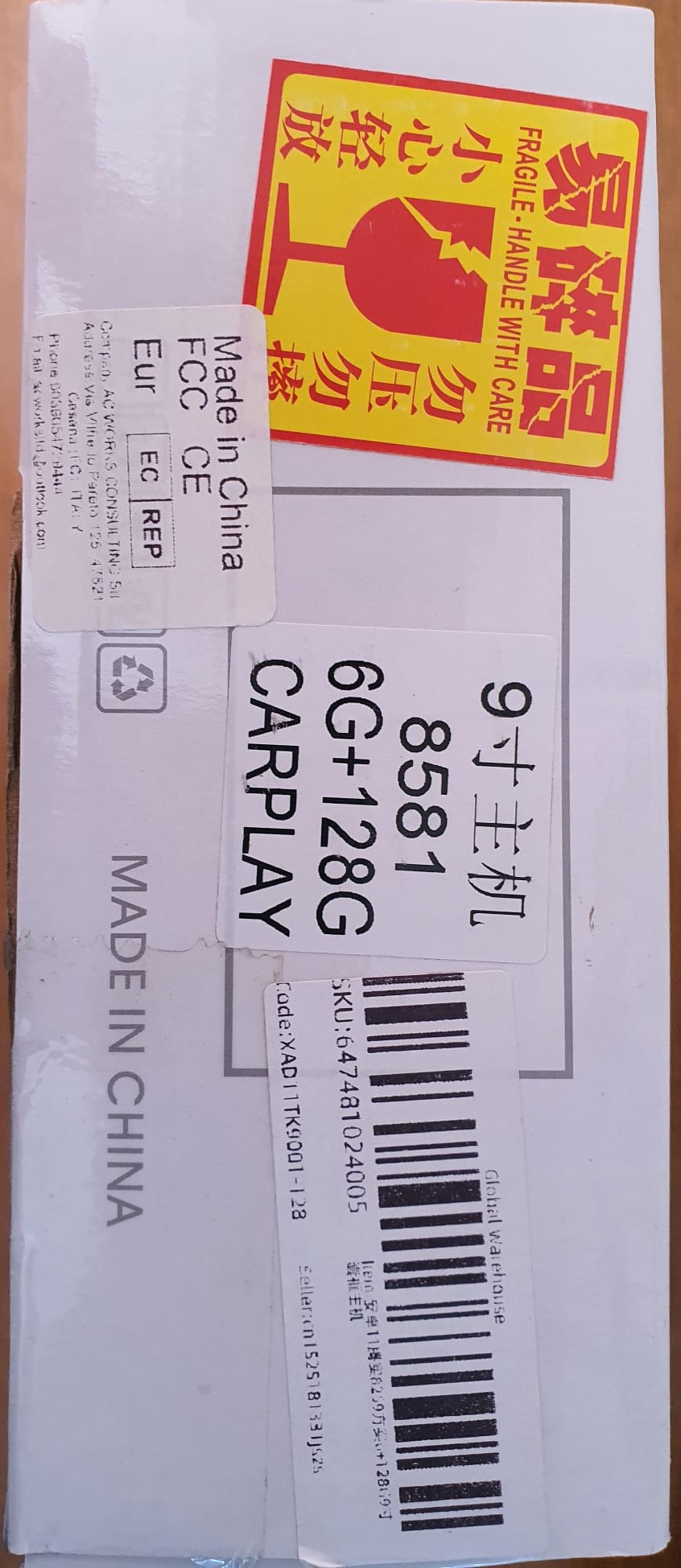
The new one is a very fast Andoid 11, octacore 1,6 Ghz 6GB/128GB device, we expect it to outlive the car this time!

We use it mainly for navigating and the new head unit has 2 IMEI’s so we can install a simcard or just share internet with our phone.  We also have android auto which can be sort of nice, although we’ll probably not use that.

The FM radio is very good, and the amplifier as well.

This is what it looks like in the car:

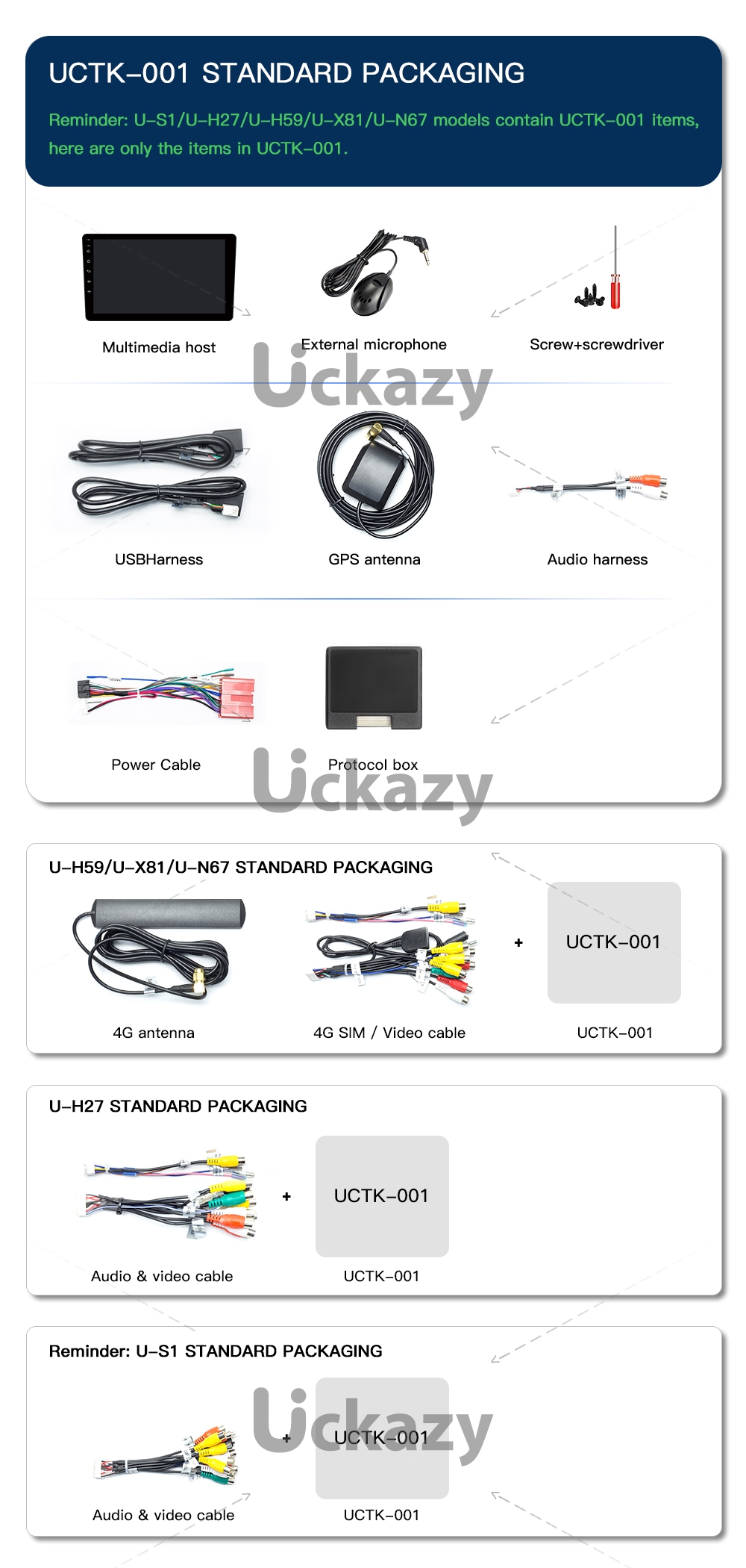
kopie aliexpress product pagina


Posted on 20 May 202321 May 2023

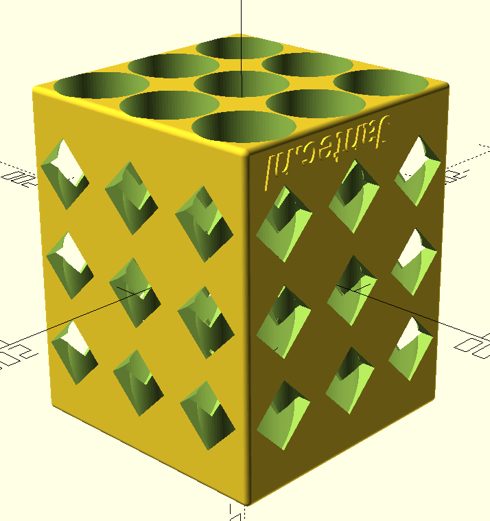
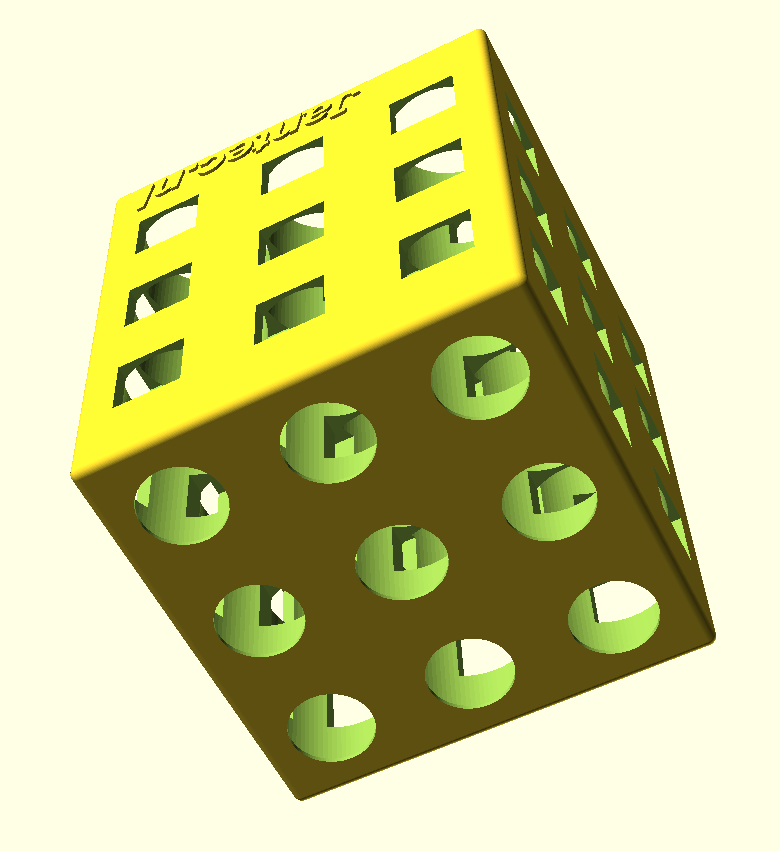
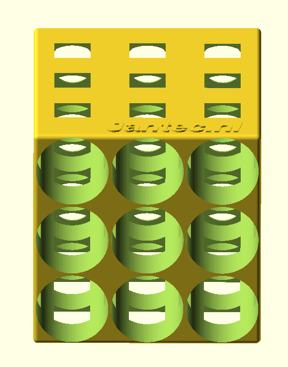
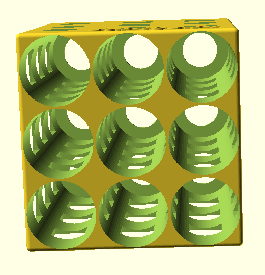
Free STL download fridge beer bottle organizer by Jantec.nl


Rear/top view

Front view

fits regular beer bottles of 330cl

//length regular beer bottle of 330cc is 238mm
//diameter regular 330cc beer bottle is 61mm

The beer bottle box in 3×3 bottles version measures 238 mm deep and  197mm wide & high.

beer bottles 3×3 fridge rack 2023 04 20


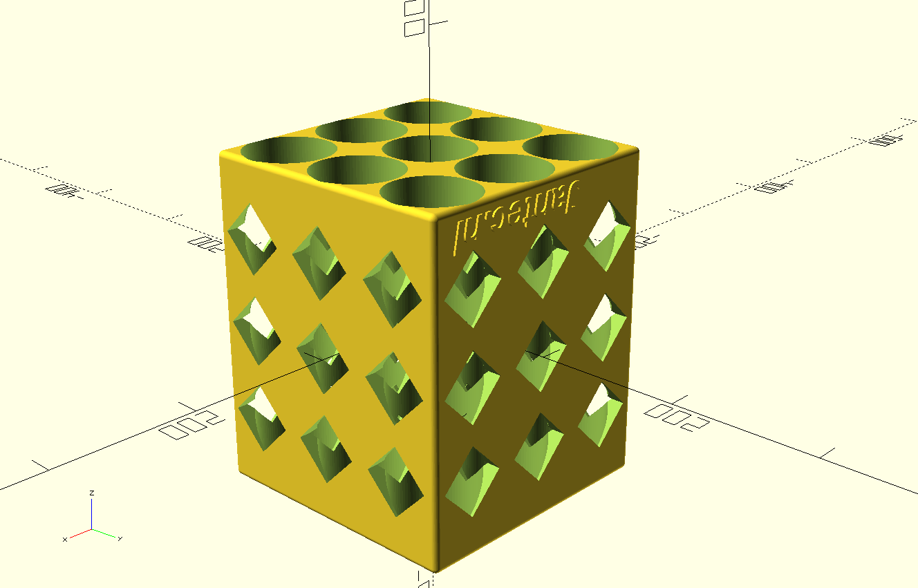
And a revised version that can be printed without support:

beer bottles fridge rack with 45deg squared side holes 2023 04 20


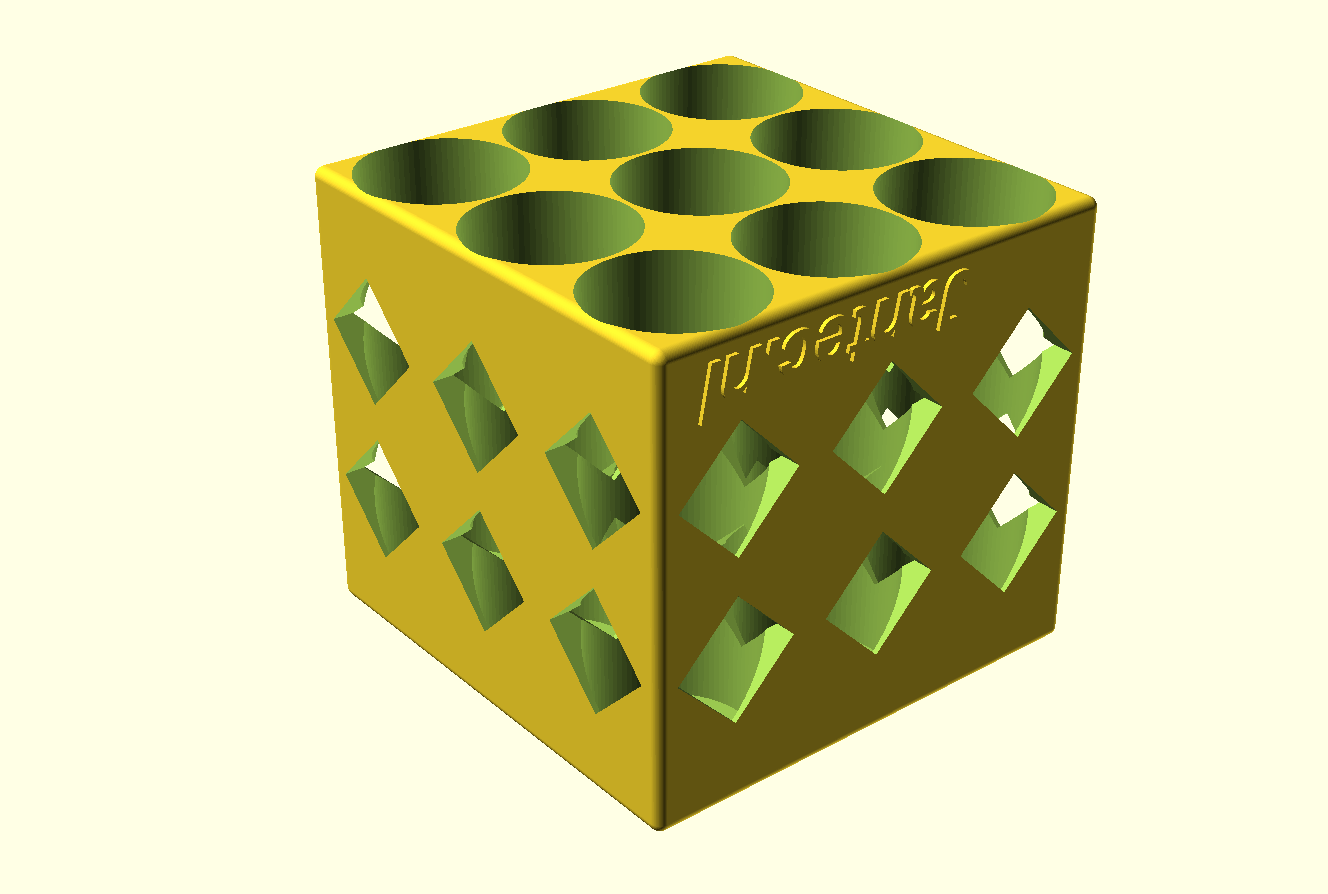
And a short version where the bottlenecks will stick out a bit:


beer bottles SHORT fridge rack with 45deg squared side holes 2023 04 20

Posted on 11 May 202324 July 2023

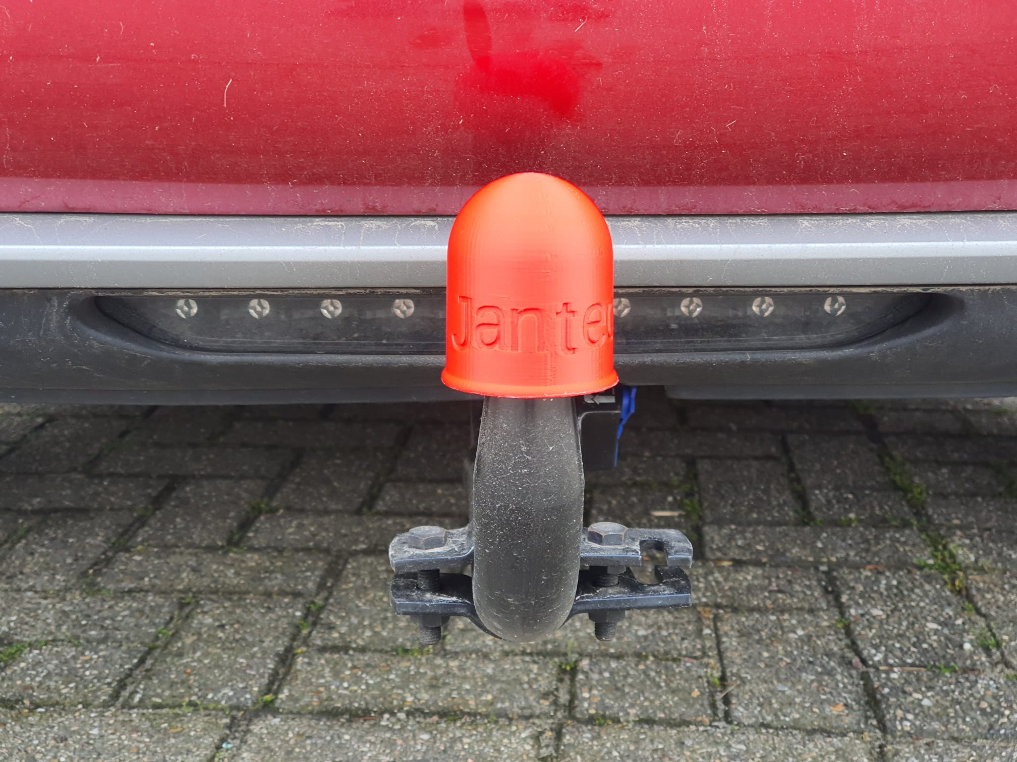
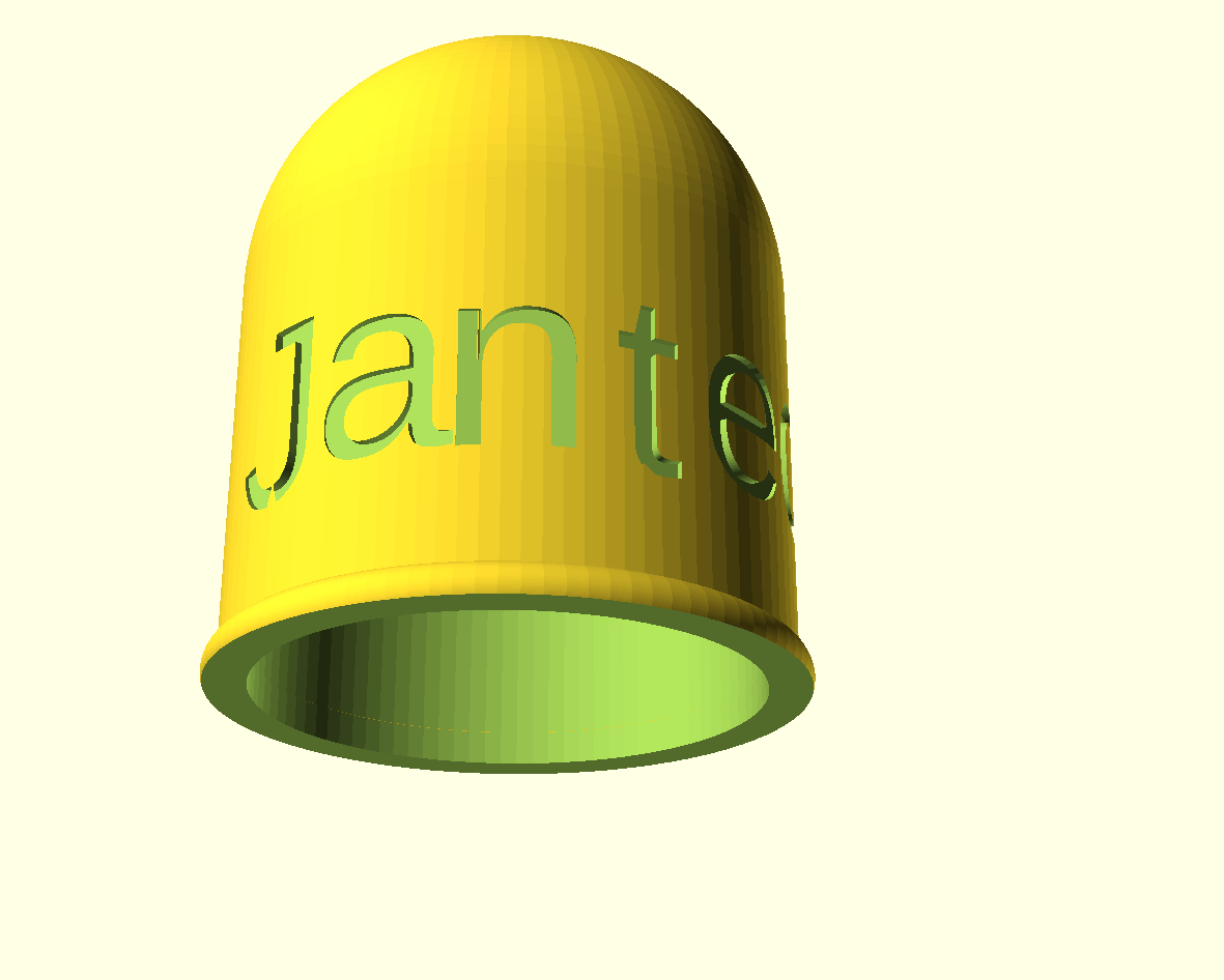
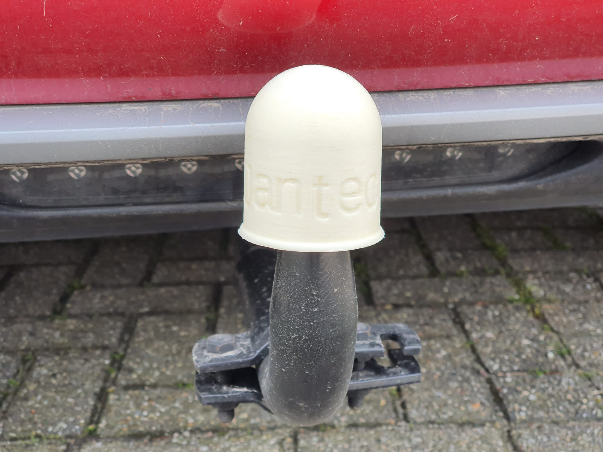
Free STL download 3d printable towbar ball cover

Tow bar ball cover 2-23 05 11 V1 Revd FREE STL DOWNLOAD

Printed this in red and white  ABS on the Voron 2.4 at 260 degrees!

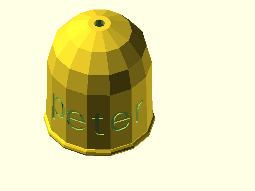
There is also a special version with facets:

Tow bar ball cover 2-23 05 11 V1 Reve facet shaped FREE DOWNLOAD


Tow bar ball cover Jimmy 2023 07 04 V1.1 facets


Tow bar ball peter cover 2023-16 06 12 V1 Facet_main FINAL size

Posted on 9 May 202310 May 2023

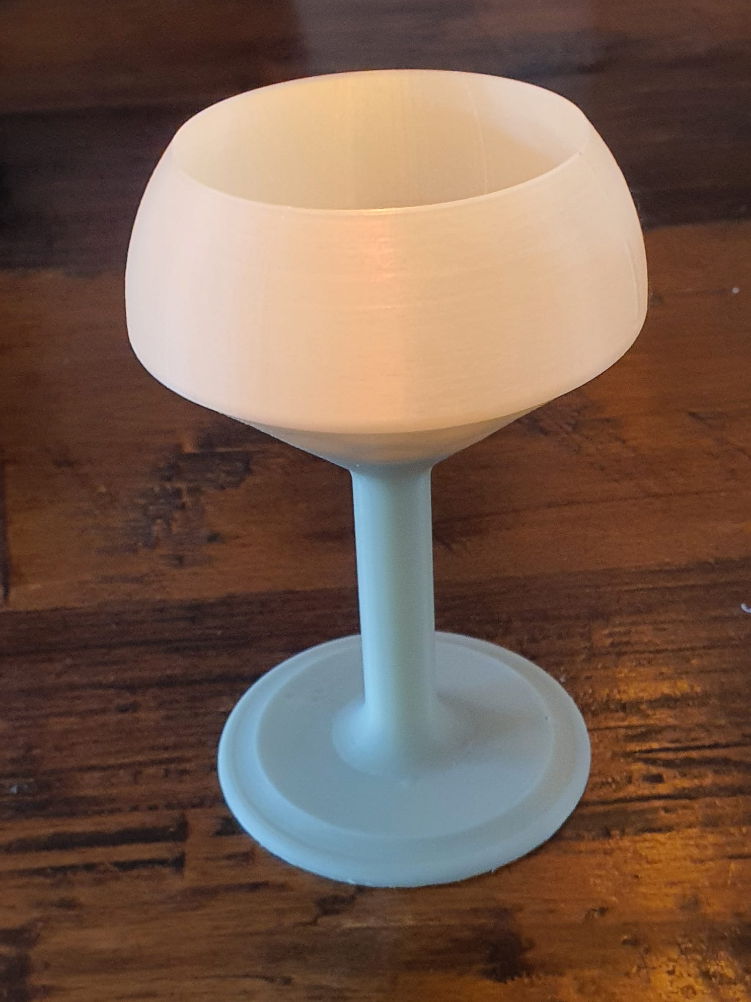
STL download for a chalice shaped wax candle holder for 22mm high 40mm diameter wax candle cups

BIG tea light chandelear on foot FINAL 2023 05 10 V19 revb FREE STL DOWNLOAD


Posted on 5 May 20239 May 2023

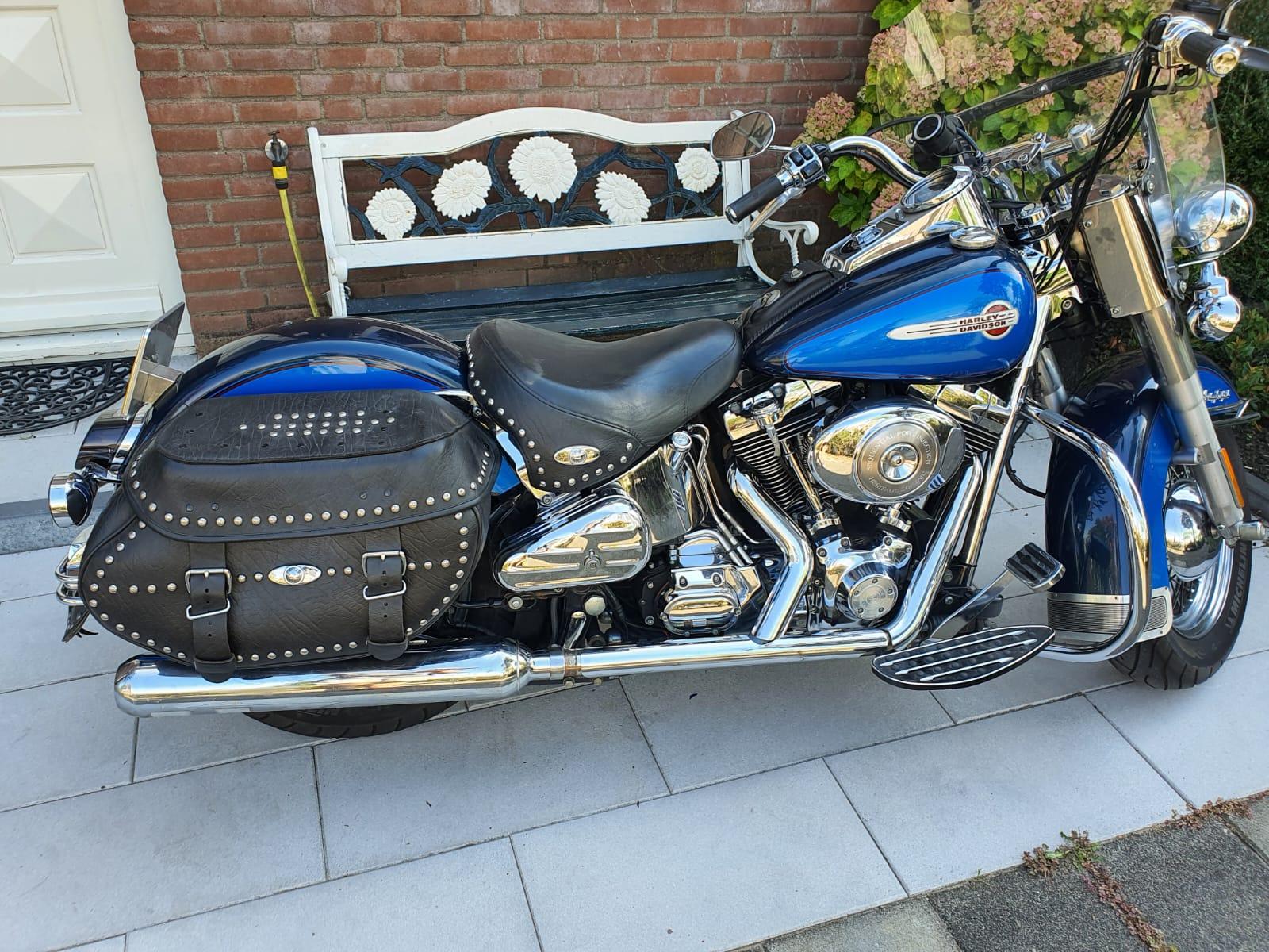
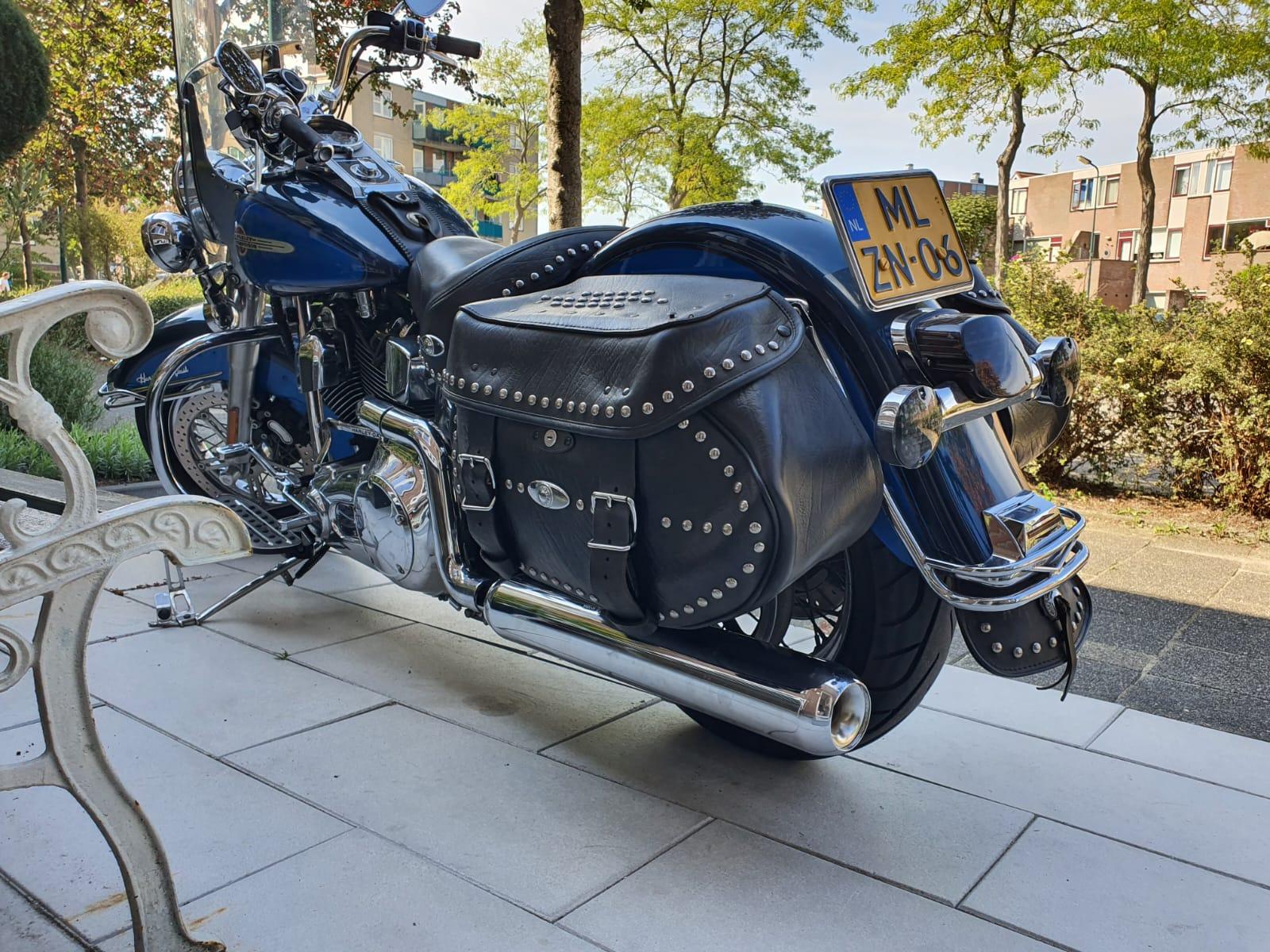
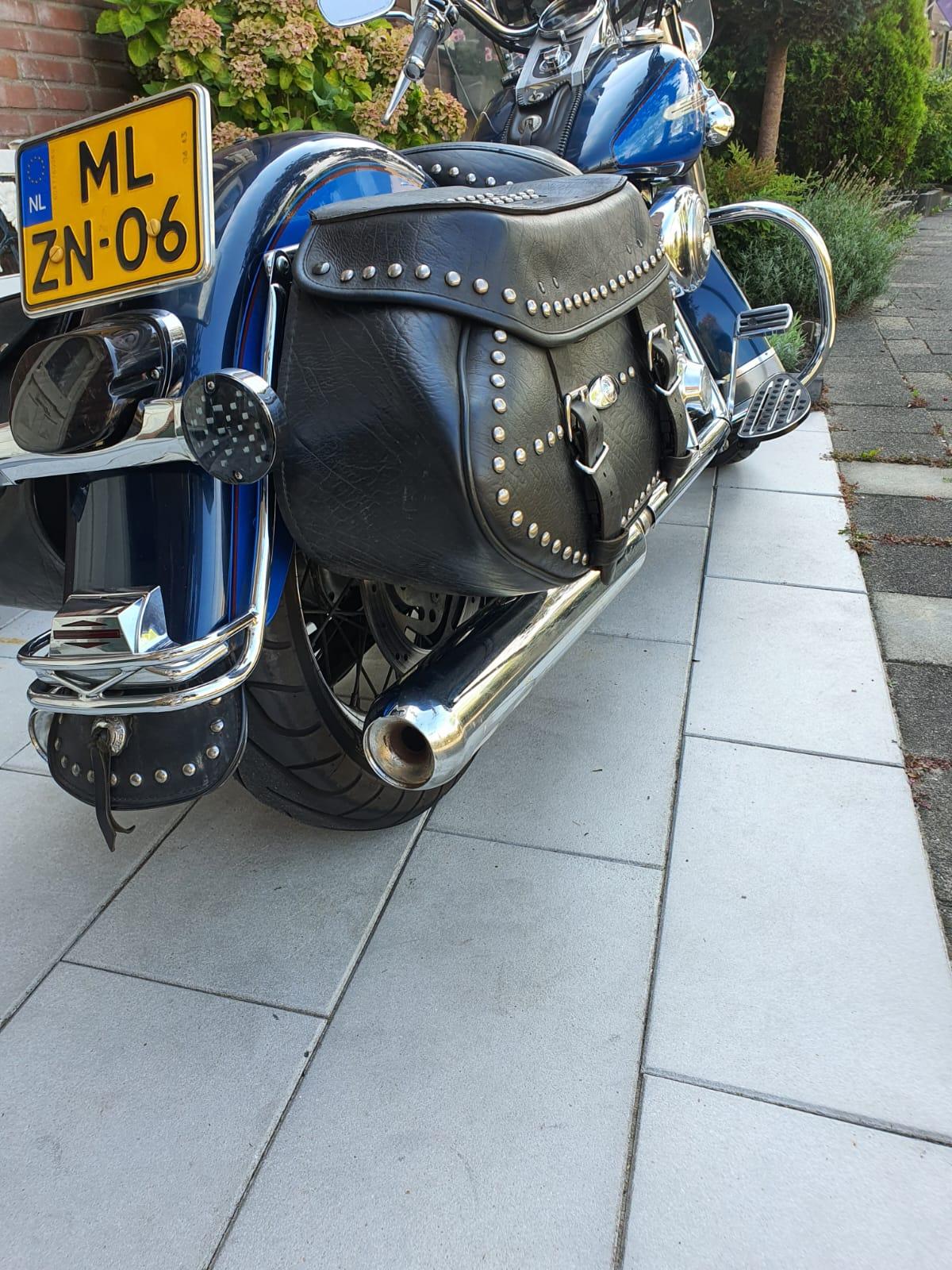
Raise the HD Heritage FLSTCI (2004) 2 inches for improved ground clearance

Whenever I drive off something higher than 4 inches,, I crash into the ledge that I drive off with the frame of the bike. Also, When driving on- and off the small typically Dutch roundabouts I often crashj both the Left- and the Right hand sided floorboards and also the jiffy on the pavement.

Coming from my previous bikes (HD-FXRS and my last was a Buell Ulysses), I never experienced these problems with those older bikes.

Therefore, I decided to raise the Heritage a bit and see whether this solves my problems. If not, I’ll sell the bike and buy me something else.

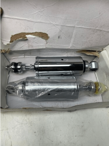
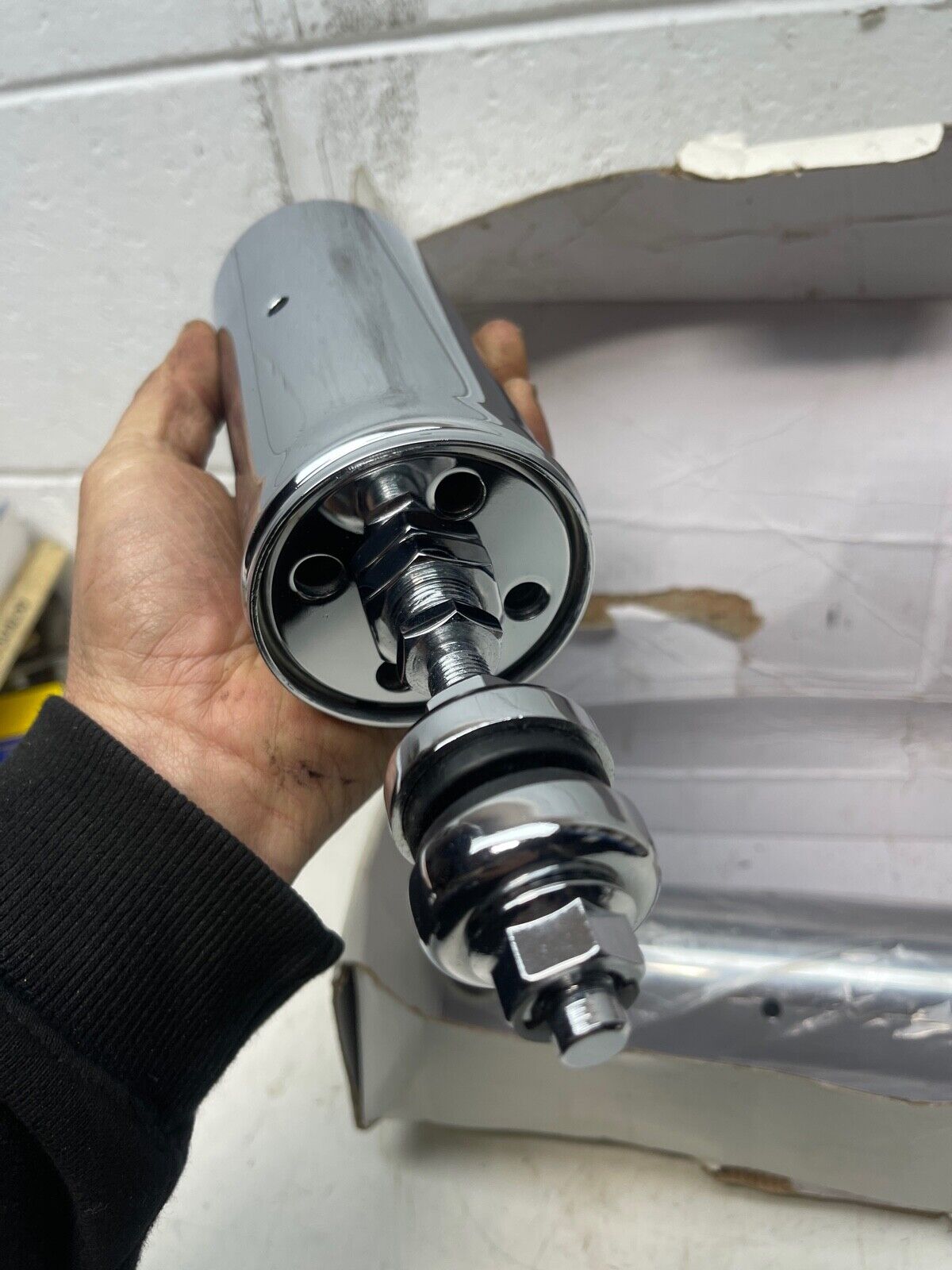
For the rear opf the bike I bought me a pair of adjustable “Ultima softail 2000-UP 116=233” shocks that I hope can be adjusted to be a bit shorter than the standard shocks.

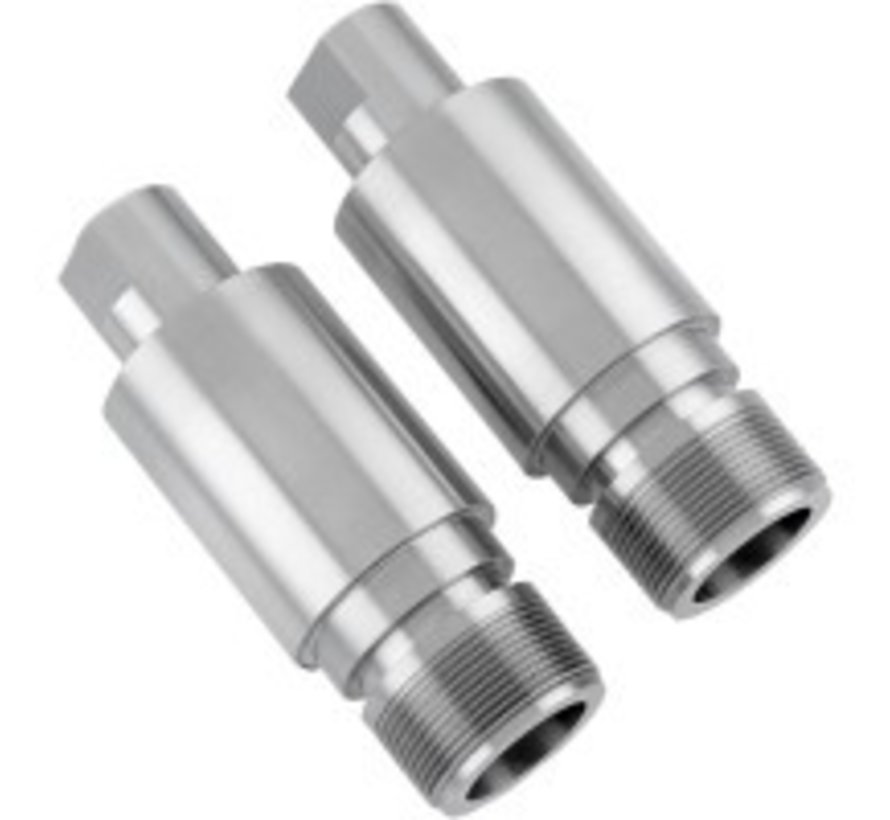
For the front, I bought me a set of Zodiac 2 inch 41mm front forks lengtheners.  See the attached photo’s:


Posted on 2 May 202327 May 2023

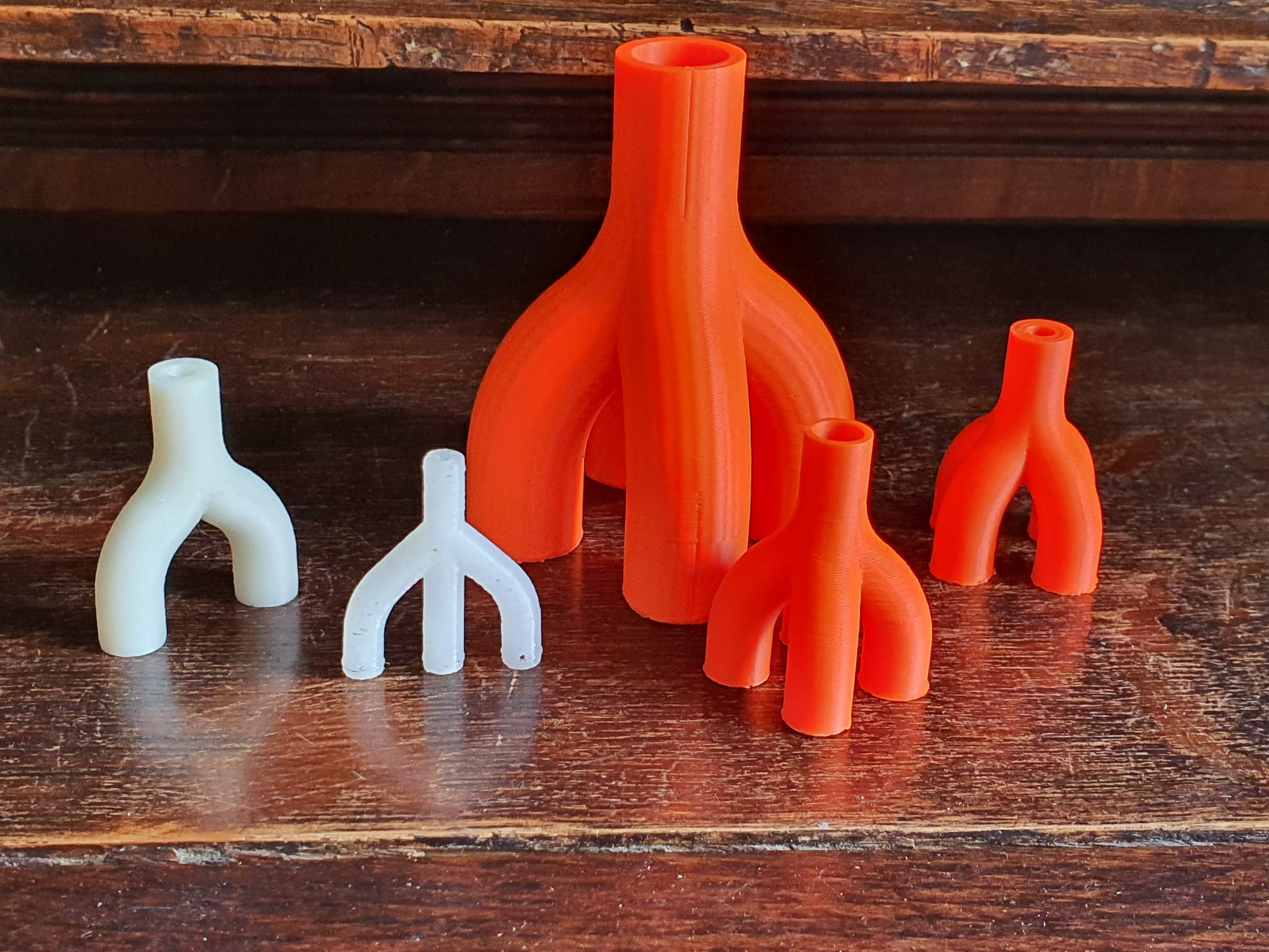
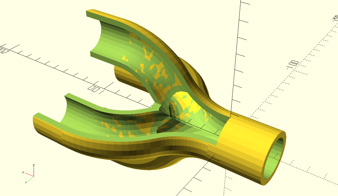
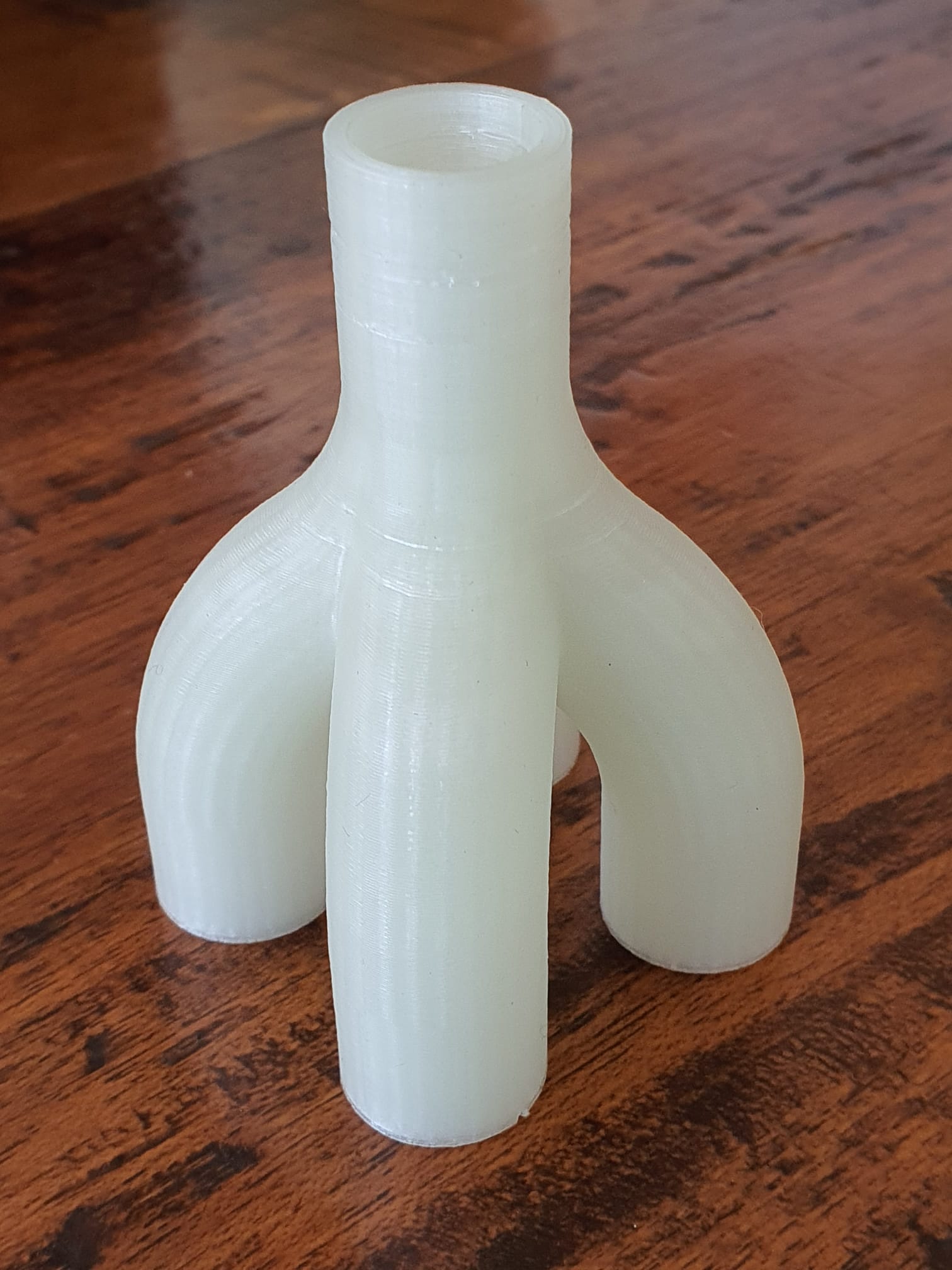
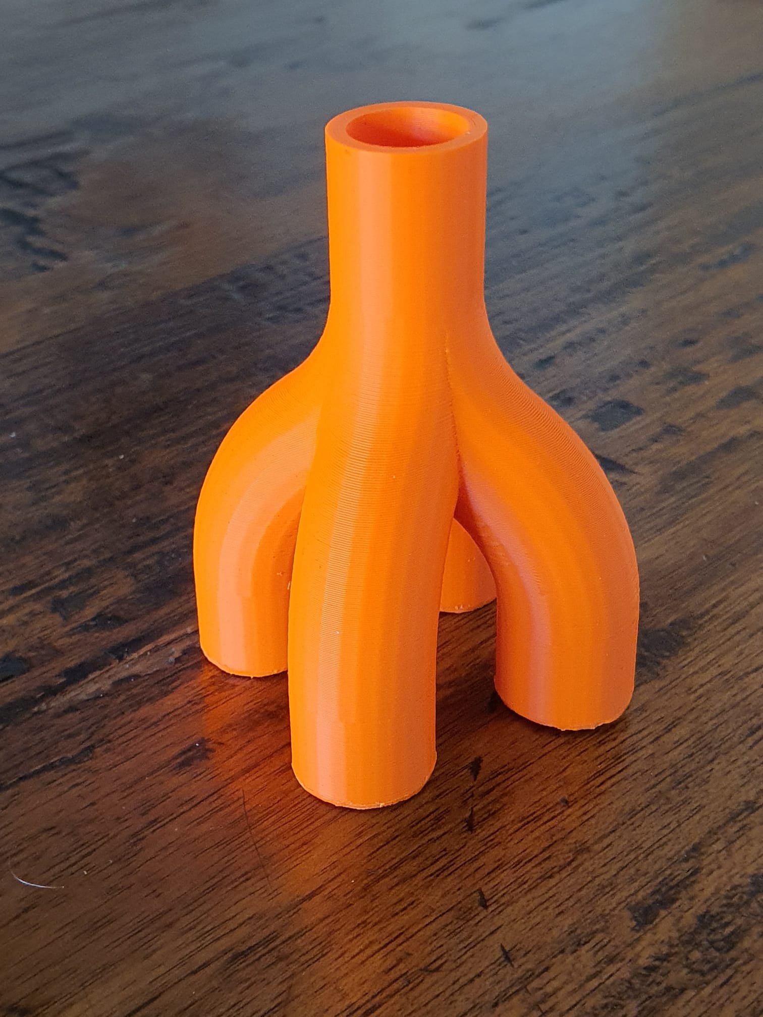
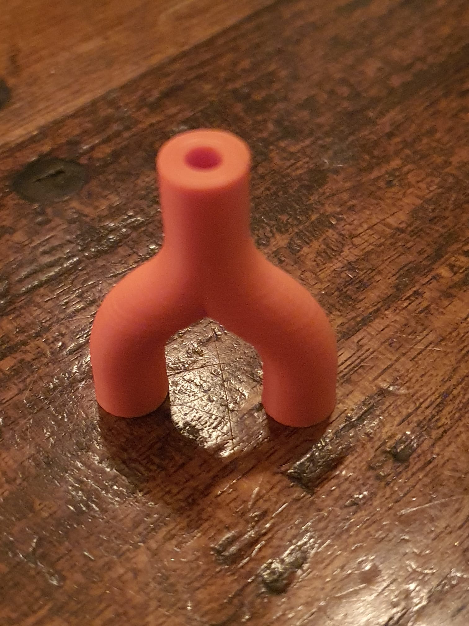
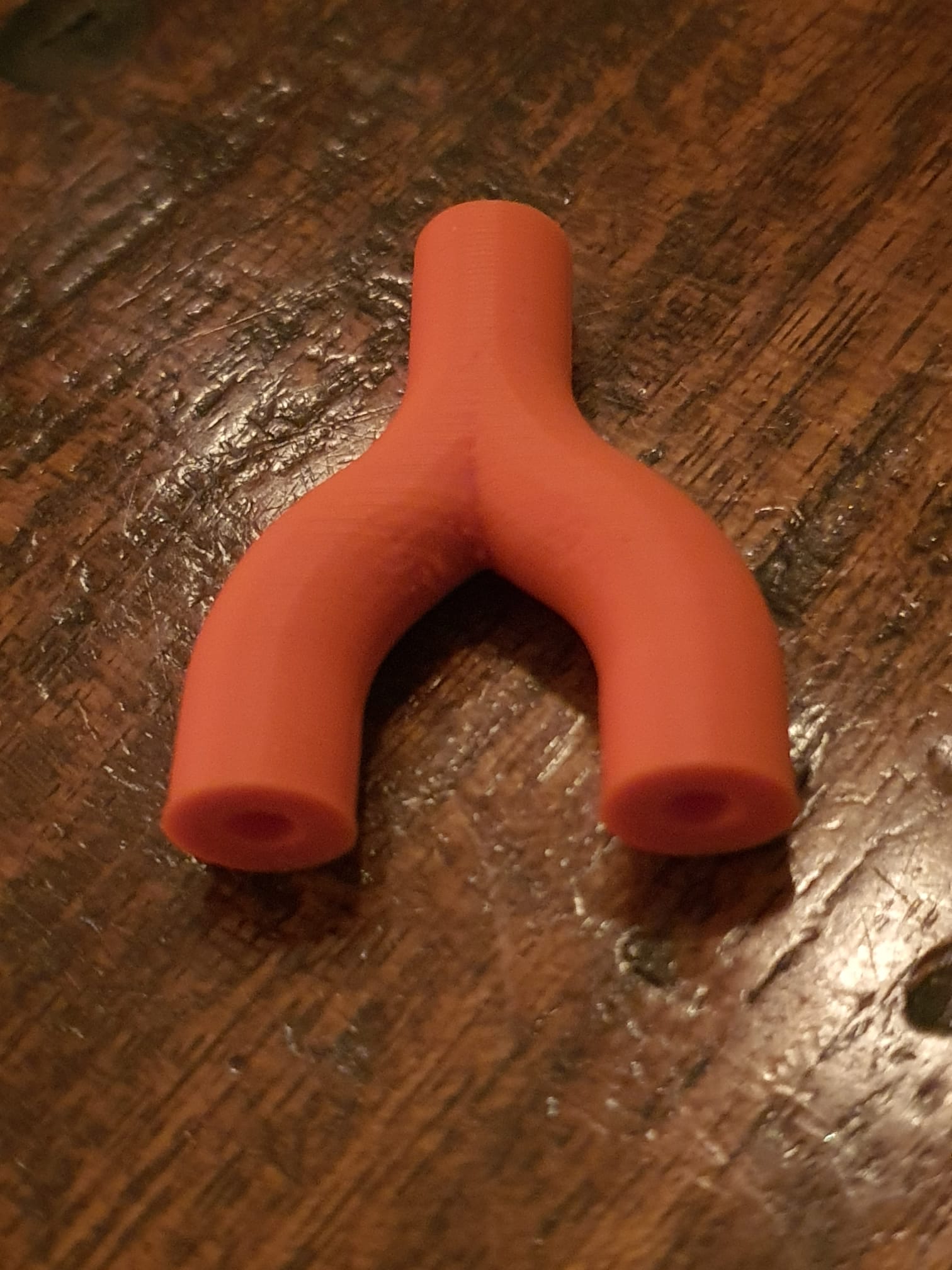
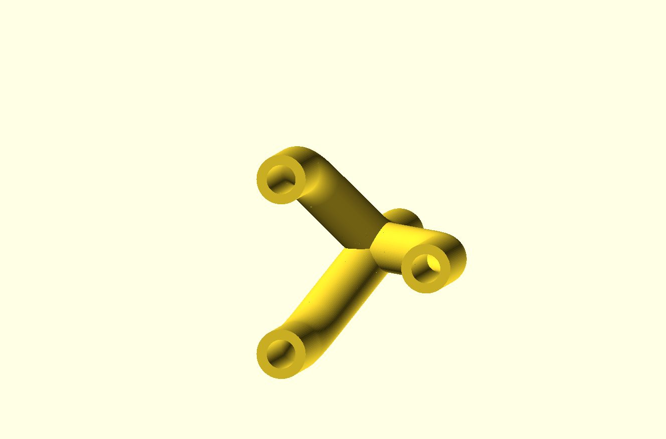
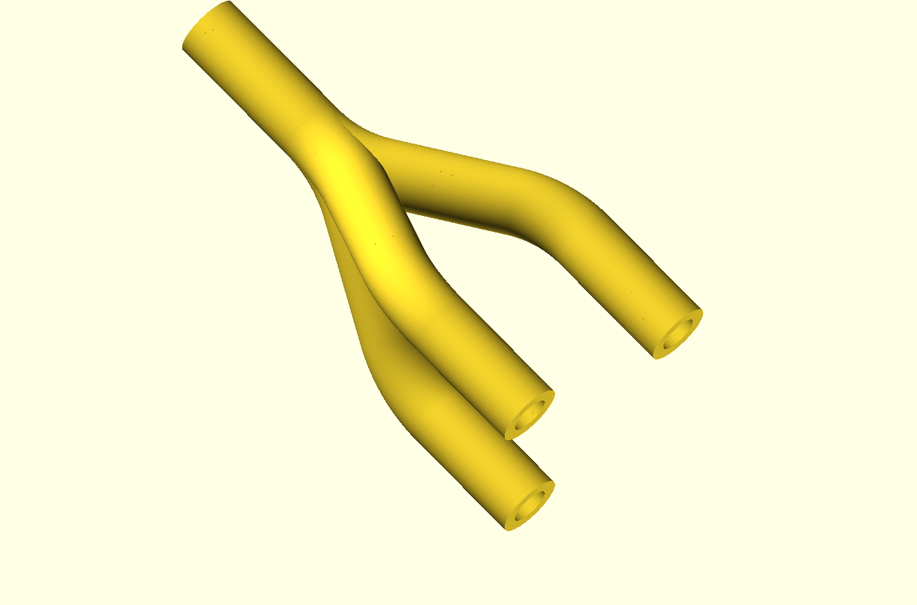
Joining multiple hollow bending tubes in Openscad with curvedPipe integrated libs

OPEN curvedPipe for pipeconnector 4 into 1 FLAT 2023 05 01 V4 dev a.SCAD

OPEN curvedPipe for pipeconnector 4 into 1 FLAT 2023 05 01 V4 dev a.STL


Inside view of the hollow pipes AND the cutouts, which required some setting changes of the Openscad program, w.r.t. higher CSG limits

Video van WhatsApp op 2023-05-02 om 23.08.14

Pipeconnector 2 into 1 all tight_hollow 2023 05 03 V4 dev b STL download


Pipeconnector 3 into 1 all hollow 2023 05 26 V5 dev d 


Posted on 18 April 202323 April 2023

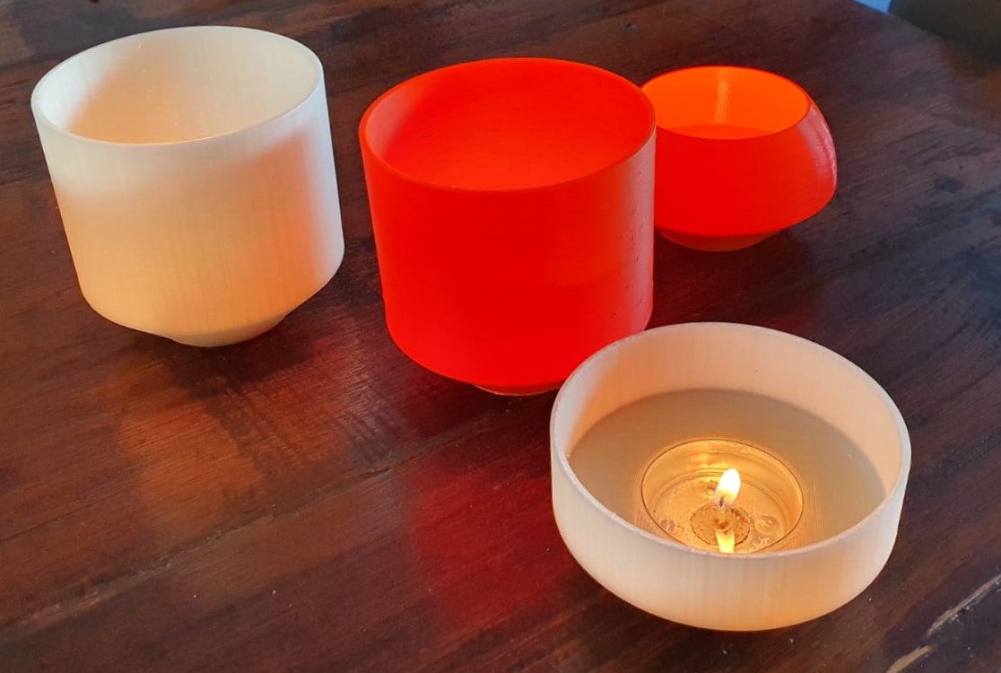
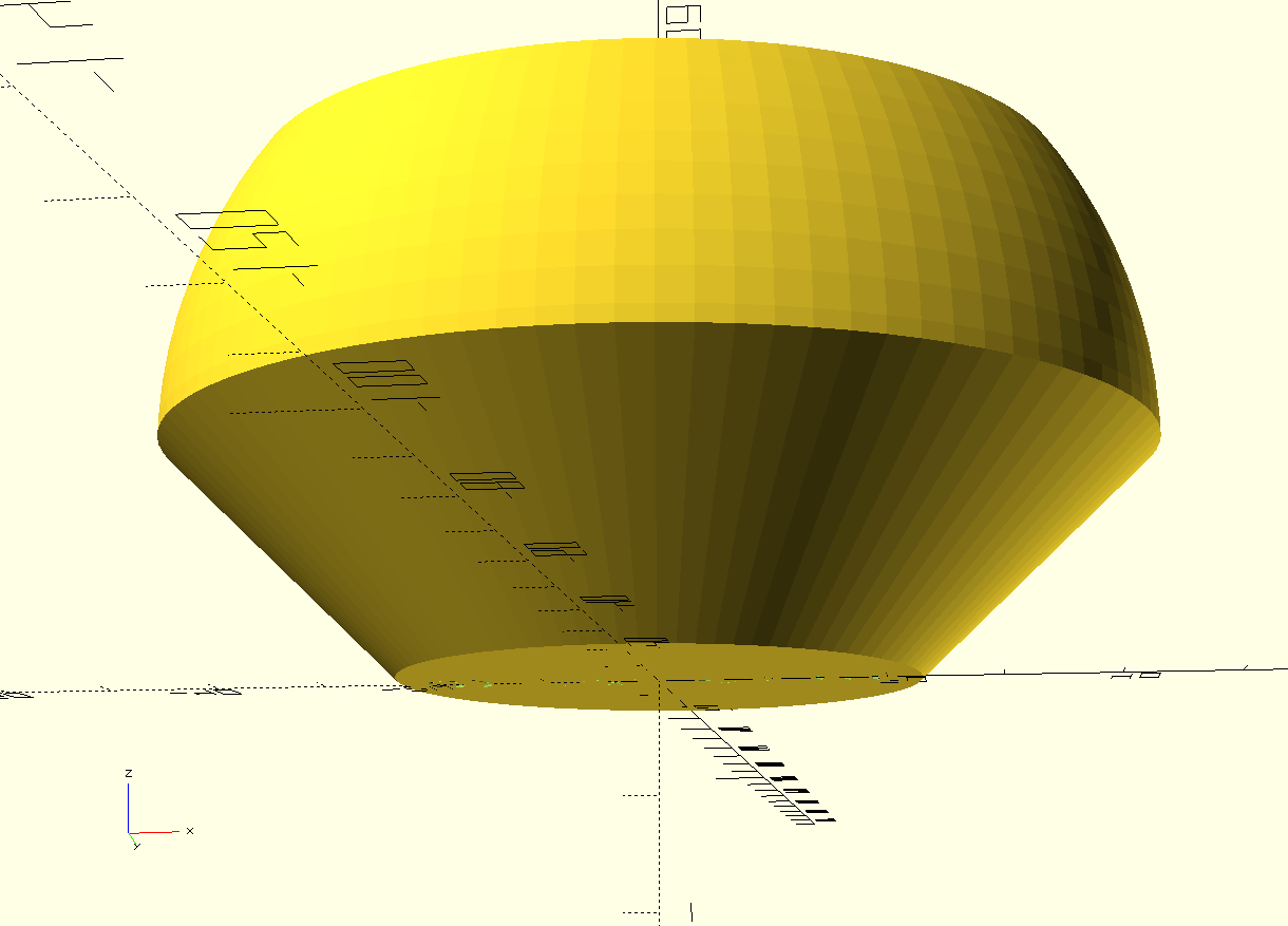
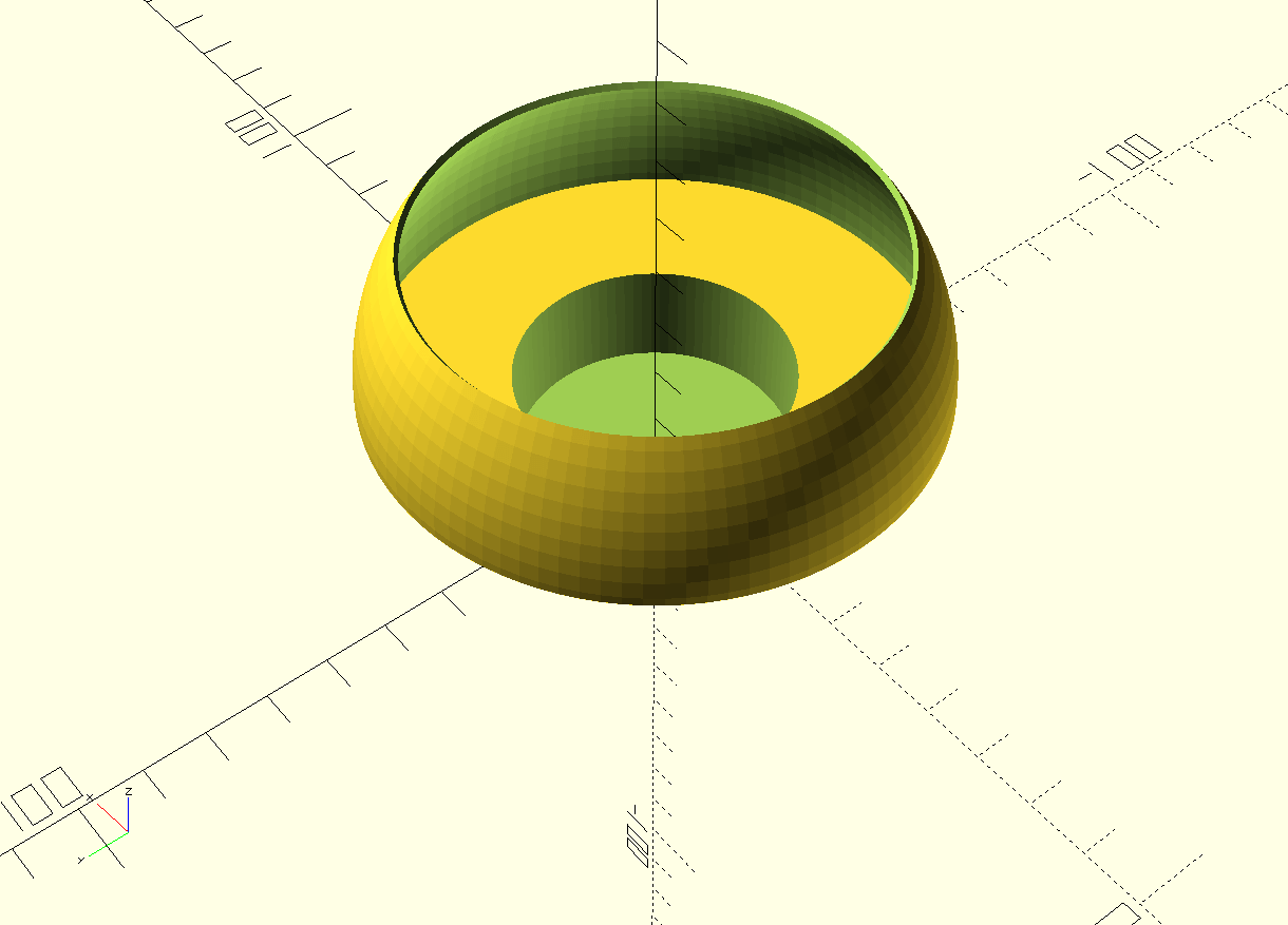
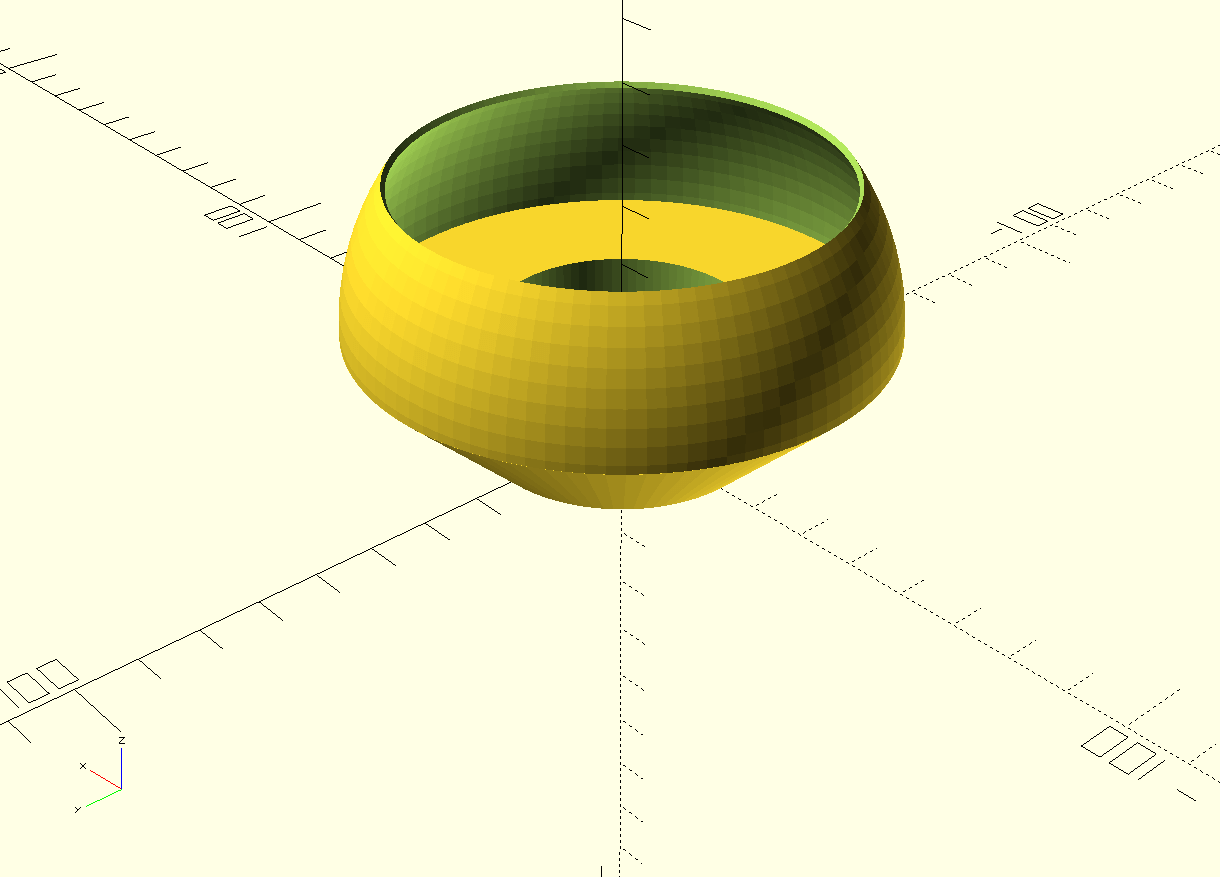
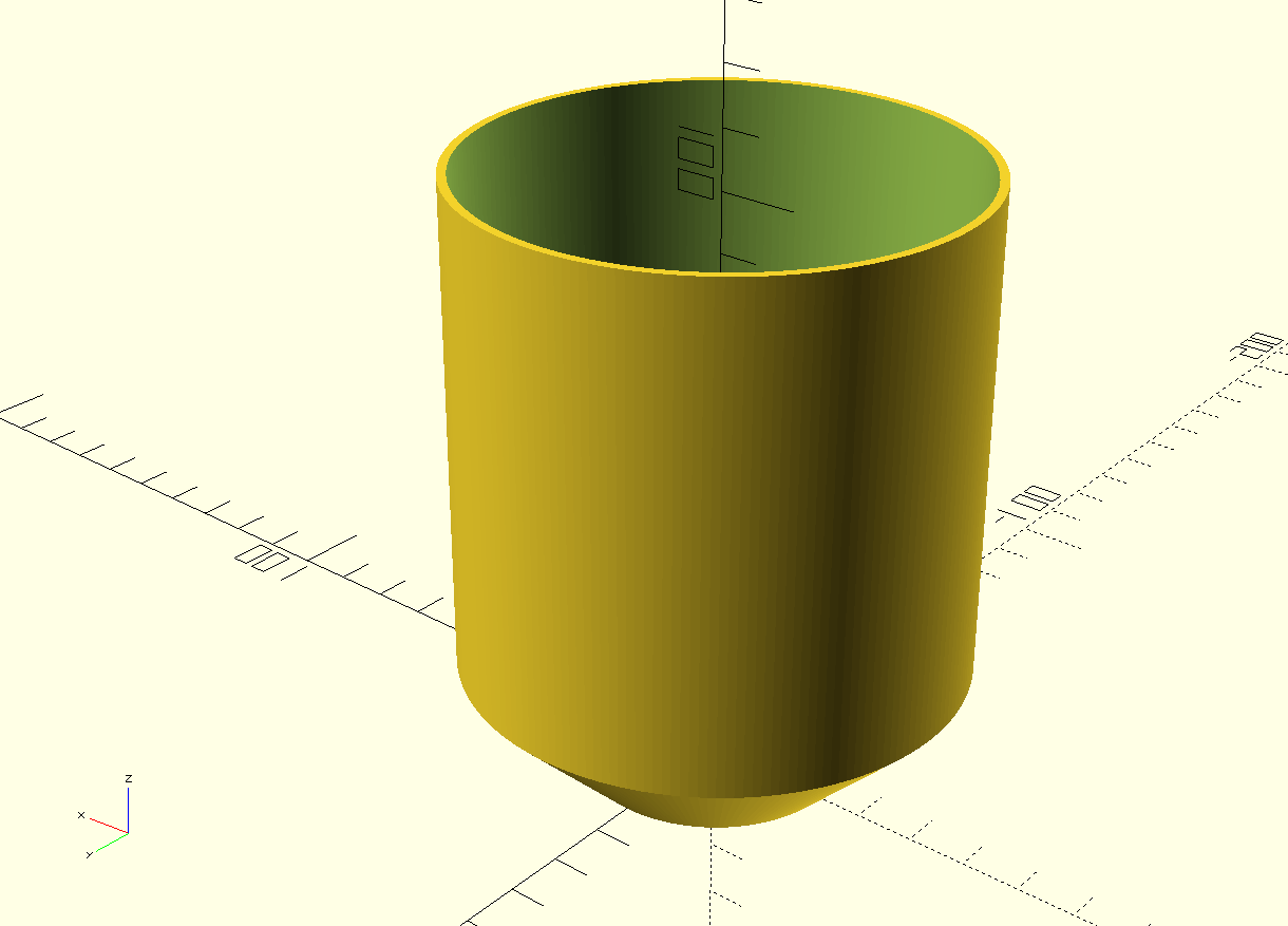
5 free printable stl files for original tabletop tealight holders

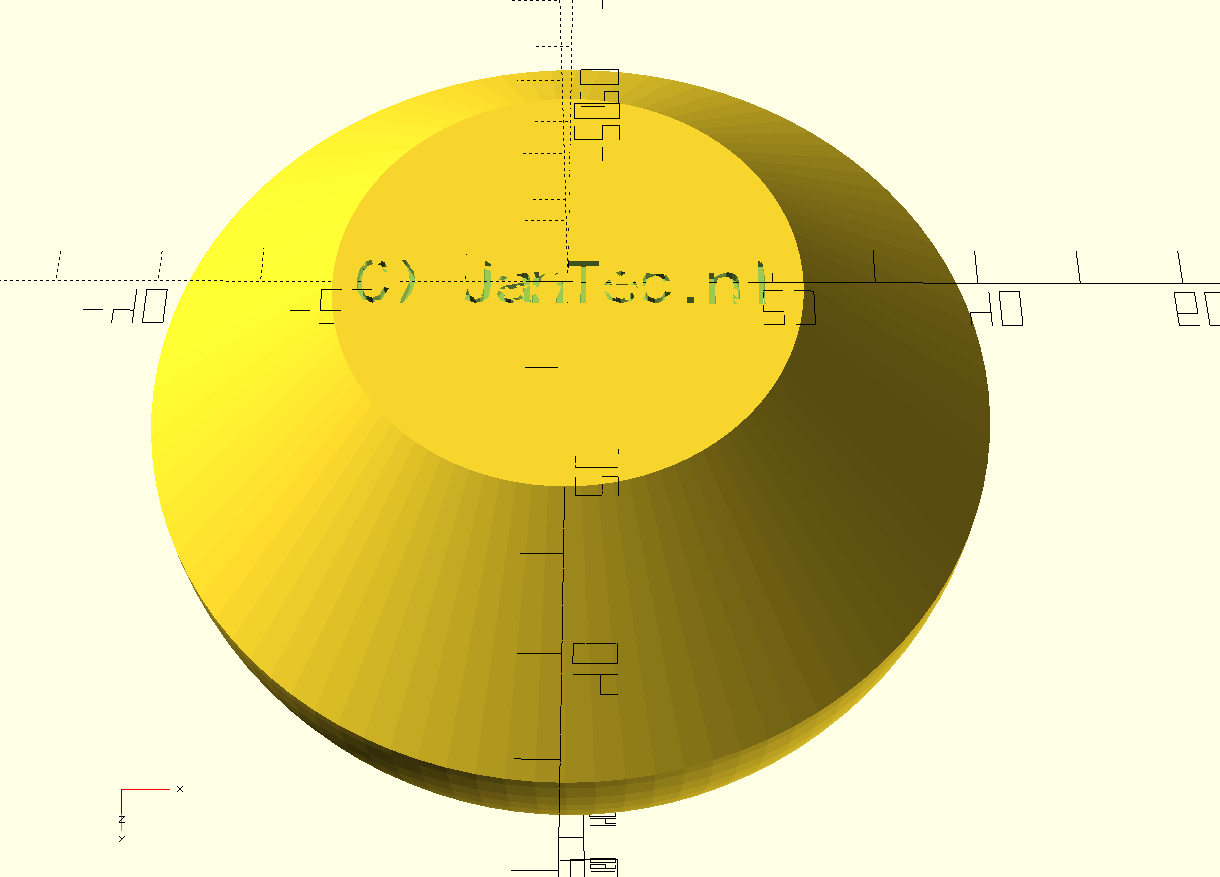
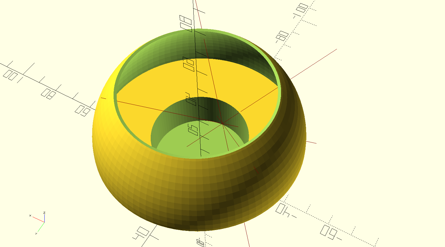
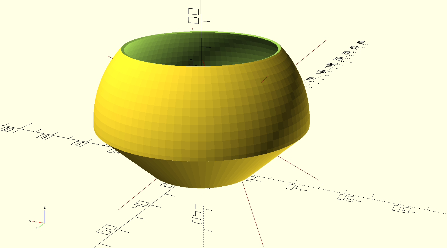
In this version, the tea light holder has a lower open spherical shape so that it can be used with a regular wax tea light.

Further down are the 4 versions of the straight flared tea light holder that are also well suited for use with a tea light.

Of course, an electric tea light is also very suitable for use with these designs.

[ NB: A design for a holder for an electric tea light with a higher inward-facing rim is in the other article. That version is not suitable for a tea light with a flame, because a flame can distort the higher, more inward edge.]

Print these STL files on a  suitable 3d-printer with heat-resistant,  fairly transparant filament for best effect!

Tea light chandelear convex and sphere Jantec.nl 2023 04 18 V9 STL DOWNLOAD


Cylinder  extra high

Tea light chandelear straight very high size Jantec.nl 2023 04 20 V2b STL DOWNLOAD


High

Tea light chandelear straight high size Jantec.nl 2023 04 20 V2b STL DOWNLOAD


Medium

Tea light chandelear straight medium size Jantec.nl 2023 04 20 V2b STL DOWNLOAD


Low

Tea light chandelear straight low size Jantec.nl 2023 04 20 V2b STL DOWNLOAD 

Posted on 16 April 202323 April 2023

printable stl file for battery-operated tea light holder

Tea light chandelear simple convex and less shaved top of thinned sphere Jantec.nl 2023 04 16 V8 STL DOWNLOAD


This holder for an electric tea light with a top higher inward edge is not suitable for a tea light with a flame because a flame can distort the higher, more inward edge and may cause a fire hazard.

STL designs better suited for original tea lights with a flame are in the article: 5 free printable STL files for a table lamp with tea light


Posted on 9 April 20231 March 2025

Dual magnetic parking extruders I3 Bear Duet2wifi build and Config files

https://jantecnl.synology.me/wp-content/uploads/2021/04/I3-dual-2021-04-02-.mp4

My dual carriage I3-bear based 3d printer is working very well.

On this page I share my latest configuration files, my build experiences like the used STL’s , schematics and so on. 

Hope you enjoy!

Be aware that the tool settings in config.g are set including relative X, Y, Z values for this build so DO NOT put this in your slicer! 

And- you need at least RRF3.3.1 for reprap FW and for DWC. 

The sensorless homimg also requires knowledge of config settings and the good news is that the Duet2wifi has this all managed by the reprap firmware.  No switches needed or complex jumper settings!

Tip for printing the parts: I used ABS for all parts. Use at least a printer with calibrated XYZ values for your specific filament. 

Do a testcube first and apply any needed adjusting to your slicer’s settings like pre-shrinking settings of the endresult and so on. 

If you don’t do this, then don’t start this build. 

It is a prerequisite to get the magnetic carriage to deliver-and get the carriages from left and right of the X-axis. 

Therefore the movement needs to be free of unneccessary friction. 

And– if you use sensorless homing any additional friction on any sensorless homed axis might lead to unintended stalls.

I added a dripstop to the left and right hand sided X-carriages, made of some thin tinned plate.

It is positioned so, that a little tension is put on the nozzle tip in the parking position. It really works very well!

Please donate $1 to my paypal account if you use (parts of) my firmware developments so I can continue to share nice stuff for you to download

The config.g for this build and the Duet2wifi is HERE

The Sys directory for the dual carriage build and Duet2wifi is HERE

The Macros directory for the dual carriage build and Duet2wifi is HERE

The build plan for the 2040 extrusion frame is HERE

2.1 version Prusa i3 MK3/MK3S Bear Z Extended 459mm Black kit 2040  Extrusion Anodized After Cut Prusa i3 MK3 Bear Profile Frame|3D Printer  Parts & Accessories| - AliExpress

The following is available in the public domain as sharable content under the user-agreements as produced by its original authors::

The STL files for the X-axis carriages and carriages are HERE

All other needed STL files for the printer are HERE

The Duet’s case and 4.3 inch Paneldue’s case are HERE

The page of the working printer is HERE

The build plans for the electronics and Duet2wifi wiring schemes are HERE


Posted on 4 April 202323 April 2023

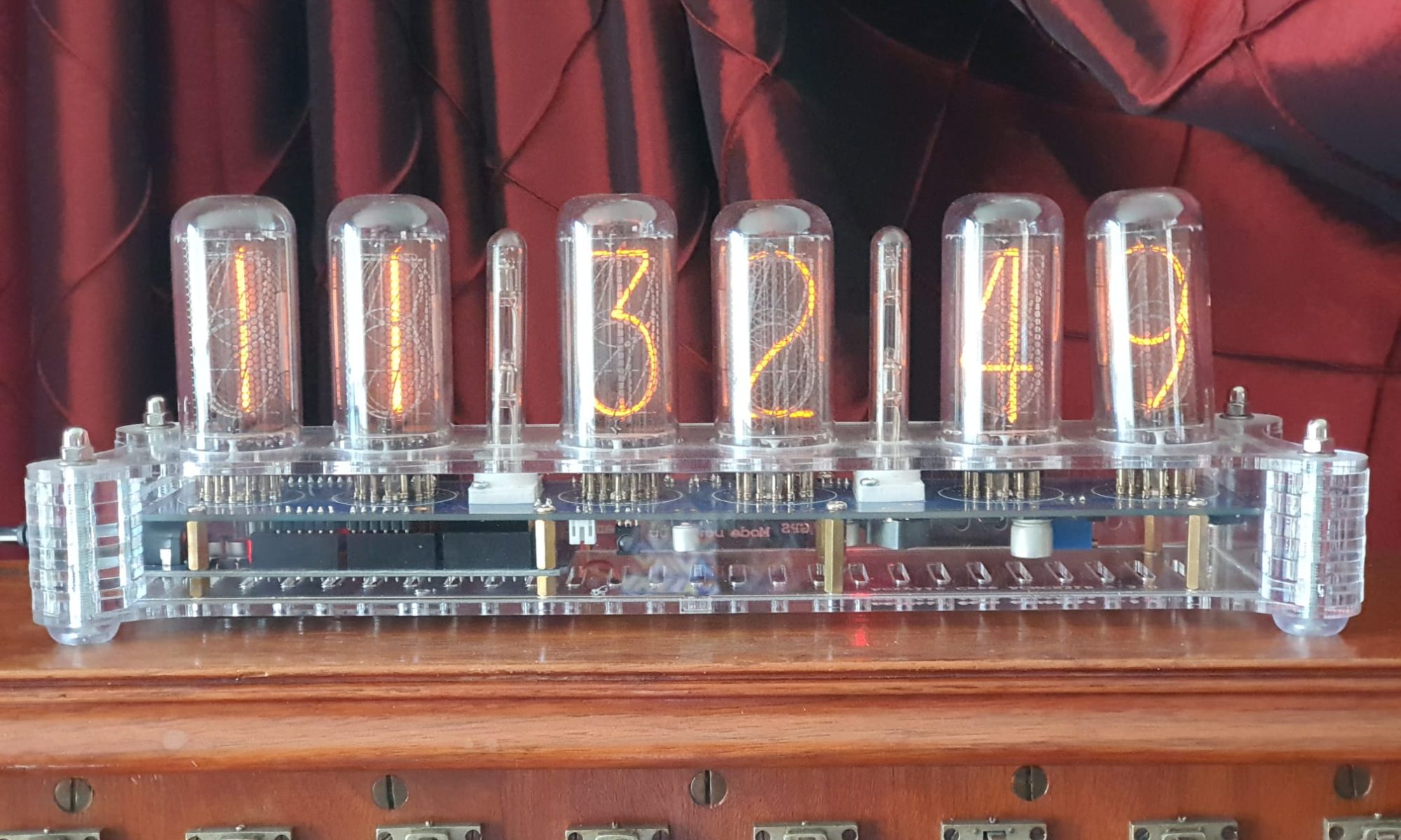
GRA-AFCH NixieClockShield_NCS318_V1_94_TZ.ino with Time zone and automated summer/winter time with example video

I added the timezone.lib plus arduino-additional code to the open-source code as GRA-AFCH made this for their  IN-18 nixie clock with Arduino Mega : NixieClockShield_NCS318_V1_94_TZ.

This is a first version that works, but it might require some coding to be done, depending on where you live.

And THIS is HOW it works:  The startup sequence is shown in the below video:

https://jantecnl.synology.me/wp-content/uploads/2023/04/Gra-Afch-startup-sequence-for-Western-European-summertime-2023-04-14-Jantec.nl_.mp4

If you’re not in Western Europe, changing the timezone will be needed.

If I want to spend some more time on it, I can make it fully automated to work anywhere in the world and make the timezone setting done via the menu buttons, requires only a one time setting upon installation.  Maybe later.

This 1ST version makes the NIXIE clock sync to UTC with the help of a to be connected standard GPS module . This was already in the code. Then, the clock changes to the correct time zone, including automatic shifting for summer- and wintertime! 

In the code, I used the Western Europe timezone- and winter/summertime settings.  Also, an example is given for a US timezone. Others can be derived from the examples that come with the newly added timezone.lib from https://github.com/JChristensen/Timezone

These are the available timezones:

// Australia Eastern Time Zone (Sydney, Melbourne)
TimeChangeRule aEDT = {“AEDT”, First, Sun, Oct, 2, 660}; // UTC + 11 hours
TimeChangeRule aEST = {“AEST”, First, Sun, Apr, 3, 600}; // UTC + 10 hours
Timezone ausET(aEDT, aEST);

// Moscow Standard Time (MSK, does not observe DST)
TimeChangeRule msk = {“MSK”, Last, Sun, Mar, 1, 180};
Timezone tzMSK(msk);

// Central European Time (Frankfurt, Paris)
TimeChangeRule CEST = {“CEST”, Last, Sun, Mar, 2, 120}; // Central European Summer Time
TimeChangeRule CET = {“CET “, Last, Sun, Oct, 3, 60}; // Central European Standard Time
Timezone CE(CEST, CET);

// United Kingdom (London, Belfast)
TimeChangeRule BST = {“BST”, Last, Sun, Mar, 1, 60}; // British Summer Time
TimeChangeRule GMT = {“GMT”, Last, Sun, Oct, 2, 0}; // Standard Time
Timezone UK(BST, GMT);

// UTC
TimeChangeRule utcRule = {“UTC”, Last, Sun, Mar, 1, 0}; // UTC
Timezone UTC(utcRule);

// US Eastern Time Zone (New York, Detroit)
TimeChangeRule usEDT = {“EDT”, Second, Sun, Mar, 2, -240}; // Eastern Daylight Time = UTC – 4 hours
TimeChangeRule usEST = {“EST”, First, Sun, Nov, 2, -300}; // Eastern Standard Time = UTC – 5 hours
Timezone usET(usEDT, usEST);

// US Central Time Zone (Chicago, Houston)
TimeChangeRule usCDT = {“CDT”, Second, Sun, Mar, 2, -300};
TimeChangeRule usCST = {“CST”, First, Sun, Nov, 2, -360};
Timezone usCT(usCDT, usCST);

// US Mountain Time Zone (Denver, Salt Lake City)
TimeChangeRule usMDT = {“MDT”, Second, Sun, Mar, 2, -360};
TimeChangeRule usMST = {“MST”, First, Sun, Nov, 2, -420};
Timezone usMT(usMDT, usMST);

// Arizona is US Mountain Time Zone but does not use DST
Timezone usAZ(usMST);

// US Pacific Time Zone (Las Vegas, Los Angeles)
TimeChangeRule usPDT = {“PDT”, Second, Sun, Mar, 2, -420};
TimeChangeRule usPST = {“PST”, First, Sun, Nov, 2, -480};
Timezone usPT(usPDT, usPST);

Be aware,the way I did this is a Q&D method since i have just hacked  this into an existing piece of code, and only do a rewrite of the RTC’s original time after every sync to GPS with the new timezone and winter/summer time rules, so RTC will then become the new local time, either summer- or wintertime.

Since the time and applying the rules of timezone+ winter/summertime is continuously refreshed, not just the time is very stable, but also the changes between winter- and summertime and vice versa are automated.

The required arduino libraries are on the GRA-AFCH Github pagine:

https://github.com/afch/NixieClock

OR-just download the zipped Libraries from our website.

It works really well, please see the zipped file here or copy/paste the arduino code below (you will need some additional files than can only be retreived from the zip-file below, though).

NixieClockShield_NCS318_V1_94_TZ.ino

NixieClockShield_NCS318_V1_94_TZ.ino:

const String FirmwareVersion = “0196TZ”;
const char HardwareVersion[] PROGMEM = {“NCS318/568 FW 1.94TZ 2021_04_04 Jantec.nl add-on for Timezones for HW 1.x HV5122 or HV5222”};

//// This ‘TZ’ firmware addition delivers automated Summer/Winter time changes based on your local time zone settings ////
//// Jantec.nl 2023-04-04 The Netherlands, Amsterdam. Please share and re-use! ////
//// This can and may be used in any CLOCK program, with possibly specific minor alteration, due to different libraries and do on ////
//// All of my add-ons are specified in the code! Cheers, Jantec.nl, NL ////
//// The approach here is to automatically change the EEPROM hours setting according to the SUMMER/WINTER timecheme ////
//// meaning: Put in the register: a) the time zone (=normal winter time) versus UTC and b) at the switching times the summer ‘+1’ change versus ‘normal’wintertime ///
//// If the user changes the hours setting, this will be overruled at every programmed time change related to summer/ winter time
//Format _X.XXX_
//NIXIE CLOCK SHIELD NCS318/568 for HW 1.x by GRA & AFCH (fominalec@gmail.com)
//1.94 26.02.2021
//Added: Сhecking the presence of a gps receiver when turned on.
//Return to the previous gps parser
//1.92 21.01.2021
//Added: defines for GPS receiver types
//1.91 29.07.2020
//The driver has been changed to support BOTH HV5122 and HV5222 registers (switching using resistor R5222 Arduino pin No. 8)
//1.90 08.06.2020
//Fixed: GPS timezone issue: added breakTime(now(), tm) to adjustTime function at Time.cpp
//1.89 03.04.2020
//Dots sync with seconds
//1.88 26.03.2020
//GPS synchronization algorithm has been changed (again)
//1.86 23.02.2020
//GPS synchronization algorithm changed
//1.85.3 23.02.2020
//Added: DS3231 internal temperature sensor self test: 5 beeps if fail.
//1.85.2 21.02.2020
//Fixed: Bug with time zones more than +-9
// GPS parser has been replaced by NEOGPS
//1.85.1 05.01.2020
//Value of “HardwareVersion” was changed to NCS318/568
//1.85 14.06.2019
//indication is working inside interrupt (only for Arduino Mega), driver v1.3 is required
//Added: support programmable leds ws2812b
//Some performance optimizations
//1.84 08.04.2018
//LEDs functions moved to external file
//LEDs freezing while music (or sound) played.
//SPI Setup moved driver’s file
//1.83 02.08.2018 (Driver v 1.1 is required)
//Fixed: Temp. reading speed fixed
//Fixed: Dots mixed up (driver was updated to v. 1.1)
//Fixed: RGB LEDs reading from EEPROM
//Fixed: Check for entering data from GPS in range
//1.82 18.07.2018 Dual Date Format
//1.81 18.02.2018 Temp. sensor present analyze
//1.80 06.08.2017
//Added: Date and Time GPS synchronization
//1.70 30.07.2017
//Added IR remote control support (Sony RM-X151) (“MODE”, “UP”, “DOWN”)
//1.60 24_07_2017
//Added: Temperature reading mode in menu and slot machine transaction
//1.0.31 27_04_2017
//Added: antipoisoning effect – slot machine
//1.021 31.01.2017
//Added: time synchronizing each 10 seconds
//Fixed: not correct time reading from RTC while start up
//1.02 17.10.2016
//Fixed: RGB color controls
//Update to Arduino IDE 1.6.12 (Time.h replaced to TimeLib.h)
//1.01
//Added RGB LEDs lock(by UP and Down Buttons)
//Added Down and Up buttons pause and resume self testing
//25.09.2016 update to HW ver 1.1
//25.05.2016

//#define tubes8
#define tubes6
//#define tubes4

#include <SPI.h>
#include <Wire.h>
#include <ClickButton.h>
#include <TimeLib.h>
#ifndef GRA_AND_AFCH_TIME_LIB_MOD
#error The “Time (TimeLib)” library modified by GRA and AFCH must be used!
#endif

//// THIS IS NEW, related to TIMEZONE add-on:
#include <Timezone.h>//https://github.com/JChristensen/Timezone
//Central European Time (Frankfurt, Paris)
TimeChangeRule myDST = {“CEST”, Last, Sun, Mar, 26, 120}; //Central European Summer Time//Daylight time = UTC +2 hours
TimeChangeRule mySTD = {“CET “, Last, Sun, Oct, 3, 60}; //Central European Standard Time (Winter)//Daylight time = UTC +1 hour
Timezone myTZ(myDST, mySTD);
//ADD AND REPLACE THE ABOVE FOR ANY OTHER REQUIRED TIMEZONE FROM THE EXAMPLES IN JChistensen’s exaples folders
// US Eastern Time Zone (New York, Detroit)
//TimeChangeRule myDST = {“EDT”, Second, Sun, Mar, 2, -240}; //Daylight time = UTC – 4 hours
//TimeChangeRule mySTD = {“EST”, First, Sun, Nov, 2, -300}; //Daylight time = UTC – 4 hours
//Timezone myTZ(myDST, mySTD);
TimeChangeRule *tcr; //pointer to the time change rule, use to get the TZ abbrev
time_t utc;
//// end of this add-on for TIMEZONE

#include <Tone.h>
#include <EEPROM.h>
#include “doIndication318_HW1.x.h”
#include <OneWire.h>
//IR remote control /////////// START /////////////////////////////
#if defined(__AVR_ATmega1280__) || defined(__AVR_ATmega2560__)

#define GPS_SYNC_INTERVAL 1800000 // in milliseconds
//#define GPS_SYNC_INTERVAL 180000 //3 minutes
unsigned long Last_Time_GPS_Sync = 0;
//bool GPS_Sync_Flag = false;
//uint32_t GPS_Sync_Interval=120000; // 2 minutes
uint32_t GPS_Sync_Interval = 60000; // first try = 1 minute
uint32_t MillsNow=0;
#define TIME_TO_TRY 60000 //1 minute
bool AttMsgWasShowed=false;

#define GPS_BUFFER_LENGTH 83

char GPS_Package[GPS_BUFFER_LENGTH];
byte GPS_position = 0;

struct GPS_DATE_TIME
{
byte GPS_hours;
byte GPS_minutes;
byte GPS_seconds;
byte GPS_day;
byte GPS_mounth;
int GPS_year;
bool GPS_Valid_Data = false;
unsigned long GPS_Data_Parsed_time;
};

GPS_DATE_TIME GPS_Date_Time;

#define PreZero(digit) ((abs(digit)<10)?”0″+String(abs(digit)):String(abs(digit)))
#include <IRremote.h>
int RECV_PIN = 4;
IRrecv irrecv(RECV_PIN);
decode_results IRresults;
// buttons codes for remote controller Sony RM-X151
#define IR_BUTTON_UP_CODE 0x6621
#define IR_BUTTON_DOWN_CODE 0x2621
#define IR_BUTTON_MODE_CODE 0x7121

class IRButtonState
{
public:
int PAUSE_BETWEEN_PACKETS = 50;
int PACKETS_QTY_IN_LONG_PRESS = 18;

private:
bool Flag = 0;
byte CNT_packets = 0;
unsigned long lastPacketTime = 0;
bool START_TIMER = false;
int _buttonCode;

public: IRButtonState::IRButtonState(int buttonCode)
{
_buttonCode = buttonCode;
}

public: int IRButtonState::checkButtonState(int receivedCode)
{
if (((millis() – lastPacketTime) > PAUSE_BETWEEN_PACKETS) && (START_TIMER == true))
{
START_TIMER = false;
if (CNT_packets >= 2) {
Flag = 0;
CNT_packets = 0;
START_TIMER = false;
return 1;
}
else {
Flag = 0;
CNT_packets = 0;
return 0;
}
}
else
{
if (receivedCode == _buttonCode) { Flag = 1;}
else
{
if (!(Flag == 1)) {return 0;}
else
{
if (!(receivedCode == 0xFFFFFFFF)) {return 0;}
}
}
CNT_packets++;
lastPacketTime = millis();
START_TIMER = true;
if (CNT_packets >= PACKETS_QTY_IN_LONG_PRESS) {
Flag = 0;
CNT_packets = 0;
START_TIMER = false;
return -1;
}
else {return 0;}
}
}
};

IRButtonState IRModeButton(IR_BUTTON_MODE_CODE);
IRButtonState IRUpButton(IR_BUTTON_UP_CODE);
IRButtonState IRDownButton(IR_BUTTON_DOWN_CODE);
#endif

int ModeButtonState = 0;
int UpButtonState = 0;
int DownButtonState = 0;

//IR remote control /////////// START /////////////////////////////

/*#define GPS_BUFFER_LENGTH 83

char GPS_Package[GPS_BUFFER_LENGTH];
byte GPS_position=0;

struct GPS_DATE_TIME
{
byte GPS_hours;
byte GPS_minutes;
byte GPS_seconds;
byte GPS_day;
byte GPS_mounth;
int GPS_year;
bool GPS_Valid_Data=false;
unsigned long GPS_Data_Parsed_time;
};
*/
//GPS_DATE_TIME GPS_Date_Time;

unsigned long GPS_Data_Parsed_time;

boolean UD, LD; // DOTS control;

byte data[12];
byte addr[8];
int celsius, fahrenheit;

#define RedLedPin 9 //MCU WDM output for red LEDs 9-g
#define GreenLedPin 6 //MCU WDM output for green LEDs 6-b
#define BlueLedPin 3 //MCU WDM output for blue LEDs 3-r
#define pinSet A0
#define pinUp A2
#define pinDown A1
//#define pinBuzzer 2
const byte pinBuzzer = 2; // pomenyal
#define pinUpperDots 12 //HIGH value light a dots
#define pinLowerDots 8 //HIGH value light a dots
#define pinTemp 7
bool RTC_present;
#define US_DateFormat 1
#define EU_DateFormat 0
//bool DateFormat=EU_DateFormat;

OneWire ds(pinTemp);
bool TempPresent = false;
#define CELSIUS 0
#define FAHRENHEIT 1

String stringToDisplay = “000000”; // Content of this string will be displayed on tubes (must be 6 chars length)
int menuPosition = 0;
// 0 – time
// 1 – date
// 2 – alarm
// 3 – 12/24 hours mode
// 4 – Temperature
// 5 – TimeZone* (Only for Ardiono Mega)

byte blinkMask = B00000000; //bit mask for blinkin digits (1 – blink, 0 – constant light)
int blankMask = B00000000; //bit mask for digits (1 – off, 0 – on)

byte dotPattern = B00000000; //bit mask for separeting dots (1 – on, 0 – off)
//B10000000 – upper dots
//B01000000 – lower dots

#define DS1307_ADDRESS 0x68
byte zero = 0x00; //workaround for issue #527
int RTC_hours, RTC_minutes, RTC_seconds, RTC_day, RTC_month, RTC_year, RTC_day_of_week;

#define TimeIndex 0
#define DateIndex 1
#define AlarmIndex 2
#define hModeIndex 3
#define TemperatureIndex 4
#define TimeZoneIndex 5
#define TimeHoursIndex 6
#define TimeMintuesIndex 7
#define TimeSecondsIndex 8
#define DateFormatIndex 9
#define DateDayIndex 10
#define DateMonthIndex 11
#define DateYearIndex 12
#define AlarmHourIndex 13
#define AlarmMinuteIndex 14
#define AlarmSecondIndex 15
#define Alarm01 16
#define hModeValueIndex 17
#define DegreesFormatIndex 18
#define HoursOffsetIndex 19

#define FirstParent TimeIndex
#define LastParent TimeZoneIndex
#define SettingsCount (HoursOffsetIndex+1)
#define NoParent 0
#define NoChild 0

//——————————-0——–1——–2——-3——–4——–5——–6——–7——–8——–9———-10——-11———12———13——-14——-15———16———17——–18———-19
// names: Time, Date, Alarm, 12/24, Temperature,TimeZone,hours, mintues, seconds, DateFormat, day, month, year, hour, minute, second alarm01 hour_format Deg.FormIndex HoursOffset
// 1 1 1 1 1 1 1 1 1 1 1 1 1 1 1 1 1 1 1 1
int parent[SettingsCount] = {NoParent, NoParent, NoParent, NoParent,NoParent,NoParent,1, 1, 1, 2, 2, 2, 2, 3, 3, 3, 3, 4, 5, 6};
int firstChild[SettingsCount] = {6, 9, 13, 17, 18, 19, 0, 0, 0, NoChild, 0, 0, 0, 0, 0, 0, 0, 0, 0, 0};
int lastChild[SettingsCount] = { 8, 12, 16, 17, 18, 19, 0, 0, 0, NoChild, 0, 0, 0, 0, 0, 0, 0, 0, 0, 0};
int value[SettingsCount] = { 0, 0, 0, 0, 0, 0, 0, 0, 0, EU_DateFormat, 0, 0, 0, 0, 0, 0, 0, 24, 0, 2};
int maxValue[SettingsCount] = { 0, 0, 0, 0, 0, 0, 23, 59, 59, US_DateFormat, 31, 12, 99, 23, 59, 59, 1, 24, FAHRENHEIT, 14};
int minValue[SettingsCount] = { 0, 0, 0, 12, 0, 0, 00, 00, 00, EU_DateFormat, 1, 1, 00, 00, 00, 00, 0, 12, CELSIUS, -12};
int blinkPattern[SettingsCount] = {
B00000000, //0
B00000000, //1
B00000000, //2
B00000000, //3
B00000000, //4
B00000000, //5
B00000011, //6
B00001100, //7
B00110000, //8
B00111111, //9
B00000011, //10
B00001100, //11
B00110000, //12
B00000011, //13
B00001100, //14
B00110000, //15
B11000000, //16
B00001100, //17
B00111111, //18
B00000011, //19
};

bool editMode = false;

long downTime = 0;
long upTime = 0;
const long settingDelay = 150;
bool BlinkUp = false;
bool BlinkDown = false;
unsigned long enteringEditModeTime = 0;
bool RGBLedsOn = true;
#define RGBLEDsEEPROMAddress 0
#define HourFormatEEPROMAddress 1
#define AlarmTimeEEPROMAddress 2 //3,4,5
#define AlarmArmedEEPROMAddress 6
#define LEDsLockEEPROMAddress 7
#define LEDsRedValueEEPROMAddress 8
#define LEDsGreenValueEEPROMAddress 9
#define LEDsBlueValueEEPROMAddress 10
#define DegreesFormatEEPROMAddress 11
#define HoursOffsetEEPROMAddress 12
#define DateFormatEEPROMAddress 13

//buttons pins declarations
ClickButton setButton(pinSet, LOW, CLICKBTN_PULLUP);
ClickButton upButton(pinUp, LOW, CLICKBTN_PULLUP);
ClickButton downButton(pinDown, LOW, CLICKBTN_PULLUP);
///////////////////

Tone tone1;
#define isdigit(n) (n >= ‘0’ && n <= ‘9’)
//char *song = “MissionImp:d=16,o=6,b=95:32d,32d#,32d,32d#,32d,32d#,32d,32d#,32d,32d,32d#,32e,32f,32f#,32g,g,8p,g,8p,a#,p,c7,p,g,8p,g,8p,f,p,f#,p,g,8p,g,8p,a#,p,c7,p,g,8p,g,8p,f,p,f#,p,a#,g,2d,32p,a#,g,2c#,32p,a#,g,2c,a#5,8c,2p,32p,a#5,g5,2f#,32p,a#5,g5,2f,32p,a#5,g5,2e,d#,8d”;
char *song = “PinkPanther:d=4,o=5,b=160:8d#,8e,2p,8f#,8g,2p,8d#,8e,16p,8f#,8g,16p,8c6,8b,16p,8d#,8e,16p,8b,2a#,2p,16a,16g,16e,16d,2e”;
//char *song=”VanessaMae:d=4,o=6,b=70:32c7,32b,16c7,32g,32p,32g,32p,32d#,32p,32d#,32p,32c,32p,32c,32p,32c7,32b,16c7,32g#,32p,32g#,32p,32f,32p,16f,32c,32p,32c,32p,32c7,32b,16c7,32g,32p,32g,32p,32d#,32p,32d#,32p,32c,32p,32c,32p,32g,32f,32d#,32d,32c,32d,32d#,32c,32d#,32f,16g,8p,16d7,32c7,32d7,32a#,32d7,32a,32d7,32g,32d7,32d7,32p,32d7,32p,32d7,32p,16d7,32c7,32d7,32a#,32d7,32a,32d7,32g,32d7,32d7,32p,32d7,32p,32d7,32p,32g,32f,32d#,32d,32c,32d,32d#,32c,32d#,32f,16c”;
//char *song=”DasBoot:d=4,o=5,b=100:d#.4,8d4,8c4,8d4,8d#4,8g4,a#.4,8a4,8g4,8a4,8a#4,8d,2f.,p,f.4,8e4,8d4,8e4,8f4,8a4,c.,8b4,8a4,8b4,8c,8e,2g.,2p”;
//char *song=”Scatman:d=4,o=5,b=200:8b,16b,32p,8b,16b,32p,8b,2d6,16p,16c#.6,16p.,8d6,16p,16c#6,8b,16p,8f#,2p.,16c#6,8p,16d.6,16p.,16c#6,16b,8p,8f#,2p,32p,2d6,16p,16c#6,8p,16d.6,16p.,16c#6,16a.,16p.,8e,2p.,16c#6,8p,16d.6,16p.,16c#6,16b,8p,8b,16b,32p,8b,16b,32p,8b,2d6,16p,16c#.6,16p.,8d6,16p,16c#6,8b,16p,8f#,2p.,16c#6,8p,16d.6,16p.,16c#6,16b,8p,8f#,2p,32p,2d6,16p,16c#6,8p,16d.6,16p.,16c#6,16a.,16p.,8e,2p.,16c#6,8p,16d.6,16p.,16c#6,16a,8p,8e,2p,32p,16f#.6,16p.,16b.,16p.”;
//char *song=”Popcorn:d=4,o=5,b=160:8c6,8a#,8c6,8g,8d#,8g,c,8c6,8a#,8c6,8g,8d#,8g,c,8c6,8d6,8d#6,16c6,8d#6,16c6,8d#6,8d6,16a#,8d6,16a#,8d6,8c6,8a#,8g,8a#,c6″;
//char *song=”WeWishYou:d=4,o=5,b=200:d,g,8g,8a,8g,8f#,e,e,e,a,8a,8b,8a,8g,f#,d,d,b,8b,8c6,8b,8a,g,e,d,e,a,f#,2g,d,g,8g,8a,8g,8f#,e,e,e,a,8a,8b,8a,8g,f#,d,d,b,8b,8c6,8b,8a,g,e,d,e,a,f#,1g,d,g,g,g,2f#,f#,g,f#,e,2d,a,b,8a,8a,8g,8g,d6,d,d,e,a,f#,2g”;
#define OCTAVE_OFFSET 0
char *p;

int notes[] = { 0,
NOTE_C4, NOTE_CS4, NOTE_D4, NOTE_DS4, NOTE_E4, NOTE_F4, NOTE_FS4, NOTE_G4, NOTE_GS4, NOTE_A4, NOTE_AS4, NOTE_B4,
NOTE_C5, NOTE_CS5, NOTE_D5, NOTE_DS5, NOTE_E5, NOTE_F5, NOTE_FS5, NOTE_G5, NOTE_GS5, NOTE_A5, NOTE_AS5, NOTE_B5,
NOTE_C6, NOTE_CS6, NOTE_D6, NOTE_DS6, NOTE_E6, NOTE_F6, NOTE_FS6, NOTE_G6, NOTE_GS6, NOTE_A6, NOTE_AS6, NOTE_B6,
NOTE_C7, NOTE_CS7, NOTE_D7, NOTE_DS7, NOTE_E7, NOTE_F7, NOTE_FS7, NOTE_G7, NOTE_GS7, NOTE_A7, NOTE_AS7, NOTE_B7
};

int fireforks[] = {0, 0, 1, //1
-1, 0, 0, //2
0, 1, 0, //3
0, 0, -1, //4
1, 0, 0, //5
0, -1, 0
}; //array with RGB rules (0 – do nothing, -1 – decrese, +1 – increse

void setRTCDateTime(byte h, byte m, byte s, byte d, byte mon, byte y, byte w = 1);

int functionDownButton = 0;
int functionUpButton = 0;
bool LEDsLock = false;

//antipoisoning transaction
bool modeChangedByUser = false;
bool transactionInProgress = false; //antipoisoning transaction
#define timeModePeriod 60000
#define dateModePeriod 5000
long modesChangePeriod = timeModePeriod;
//end of antipoisoning transaction

bool GPS_sync_flag=false;

extern const int LEDsDelay;

/*******************************************************************************************************
Init Programm
*******************************************************************************************************/
void setup()
{
Wire.begin();
//setRTCDateTime(23,40,00,25,7,15,1);

Serial.begin(115200);
#if defined(__AVR_ATmega1280__) || defined(__AVR_ATmega2560__)
Serial1.begin(9600);
digitalWrite(19, HIGH);
#endif


if (EEPROM.read(HourFormatEEPROMAddress) != 12) value[hModeValueIndex] = 24; else value[hModeValueIndex] = 12;
if (EEPROM.read(RGBLEDsEEPROMAddress) != 0) RGBLedsOn = true; else RGBLedsOn = false;
if (EEPROM.read(AlarmTimeEEPROMAddress) == 255) value[AlarmHourIndex] = 0; else value[AlarmHourIndex] = EEPROM.read(AlarmTimeEEPROMAddress);
if (EEPROM.read(AlarmTimeEEPROMAddress + 1) == 255) value[AlarmMinuteIndex] = 0; else value[AlarmMinuteIndex] = EEPROM.read(AlarmTimeEEPROMAddress + 1);
if (EEPROM.read(AlarmTimeEEPROMAddress + 2) == 255) value[AlarmSecondIndex] = 0; else value[AlarmSecondIndex] = EEPROM.read(AlarmTimeEEPROMAddress + 2);
if (EEPROM.read(AlarmArmedEEPROMAddress) == 255) value[Alarm01] = 0; else value[Alarm01] = EEPROM.read(AlarmArmedEEPROMAddress);
if (EEPROM.read(LEDsLockEEPROMAddress) == 255) LEDsLock = false; else LEDsLock = EEPROM.read(LEDsLockEEPROMAddress);
if (EEPROM.read(DegreesFormatEEPROMAddress) == 255) value[DegreesFormatIndex] = CELSIUS; else value[DegreesFormatIndex] = EEPROM.read(DegreesFormatEEPROMAddress);
if (EEPROM.read(HoursOffsetEEPROMAddress) == 255) value[HoursOffsetIndex] = value[HoursOffsetIndex]; else value[HoursOffsetIndex] = EEPROM.read(HoursOffsetEEPROMAddress) + minValue[HoursOffsetIndex];

//// needed to set this HoursOffsetIndex variable to 0 since we will use the timezone lib (local timezone and summer/winter time add-ons by Jantec.nl)
value[HoursOffsetIndex] = 0;
EEPROM.write(HoursOffsetEEPROMAddress, 0);

if (EEPROM.read(DateFormatEEPROMAddress) == 255) value[DateFormatIndex] = value[DateFormatIndex]; else value[DateFormatIndex] = EEPROM.read(DateFormatEEPROMAddress);

//Serial.print(F(“led lock=”));
//Serial.println(LEDsLock);

pinMode(RedLedPin, OUTPUT);
pinMode(GreenLedPin, OUTPUT);
pinMode(BlueLedPin, OUTPUT);

tone1.begin(pinBuzzer);
song = parseSong(song);

pinMode(LEpin, OUTPUT);

// SPI setup
SPISetup();
LEDsSetup();
//buttons pins inits
pinMode(pinSet, INPUT_PULLUP);
pinMode(pinUp, INPUT_PULLUP);
pinMode(pinDown, INPUT_PULLUP);
////////////////////////////
pinMode(pinBuzzer, OUTPUT);

//buttons objects inits
setButton.debounceTime = 20; // Debounce timer in ms
setButton.multiclickTime = 30; // Time limit for multi clicks
setButton.longClickTime = 2000; // time until “held-down clicks” register

upButton.debounceTime = 20; // Debounce timer in ms
upButton.multiclickTime = 30; // Time limit for multi clicks
upButton.longClickTime = 2000; // time until “held-down clicks” register

downButton.debounceTime = 20; // Debounce timer in ms
downButton.multiclickTime = 30; // Time limit for multi clicks
downButton.longClickTime = 2000; // time until “held-down clicks” register

#if defined(__AVR_ATmega1280__) || defined(__AVR_ATmega2560__)
timerSetup();
#endif
//!!!!!!!!!!!!!!!!!!!!!!!!!!!!!!!!!!!!!!!!!!!!!!!!
doTest();
//!!!!!!!!!!!!!!!!!!!!!!!!!!!!!!!!!!!!!!!!!!!!!!!
if (LEDsLock == 1)
{
setLEDsFromEEPROM();
}
getRTCTime();
byte prevSeconds = RTC_seconds;
unsigned long RTC_ReadingStartTime = millis();
RTC_present = true;
while (prevSeconds == RTC_seconds)
{
getRTCTime();
//Serial.println(RTC_seconds);
if ((millis() – RTC_ReadingStartTime) > 3000)
{
#ifdef DEBUG
Serial.println(F(“Warning! RTC DON’T RESPOND!”));
#endif
RTC_present = false;
break;
}
}
setTime(RTC_hours, RTC_minutes, RTC_seconds, RTC_day, RTC_month, RTC_year);

#if defined(__AVR_ATmega1280__) || defined(__AVR_ATmega2560__)
irrecv.blink13(false);
irrecv.enableIRIn(); // Start the receiver
#endif

//// add-ons for TIMEZONE
time_t utc = now();
time_t local = myTZ.toLocal(utc, &tcr);
Serial.println();
printDateTime(utc, “UTC”);
printDateTime(local, tcr -> abbrev);
delay(1000);//was 10000
//// end of add-ons for TIMEZONE

}

int rotator = 0; //index in array with RGB “rules” (increse by one on each 255 cycles)
int cycle = 0; //cycles counter
int RedLight = 255;
int GreenLight = 0;
int BlueLight = 0;
unsigned long prevTime = 0; // time of lase tube was lit
unsigned long prevTime4FireWorks = 0; //time of last RGB changed
//int minuteL=0; //младшая цифра минут

/***************************************************************************************************************
MAIN Programm
***************************************************************************************************************/
void loop() {

if (((millis() % 10000) == 0) && (RTC_present)) //synchronize with RTC every 10 seconds
{
getRTCTime();

setTime(RTC_hours, RTC_minutes, RTC_seconds, RTC_day, RTC_month, RTC_year);
// 4 lines of time zone & winter/summer time additions by Jantec.nl 2023 0404
time_t utc = now();
time_t local = myTZ.toLocal(utc, &tcr);
setTime(myTZ.toLocal(utc, &tcr));
EEPROM.write(DateFormatEEPROMAddress, value[myTZ.toLocal(utc, &tcr)]);

//Serial.println(F(“Sync”));
}

#if defined(__AVR_ATmega1280__) || defined(__AVR_ATmega2560__)

MillsNow=millis();
if ((MillsNow – Last_Time_GPS_Sync) > GPS_Sync_Interval)
{
//GPS_Sync_Interval = GPS_SYNC_INTERVAL; // <—-!
//GPS_Sync_Flag = 0;
if (AttMsgWasShowed==false)
{
Serial.println(F(“Attempt to sync with GPS.”));
AttMsgWasShowed=true;
}
GetDataFromSerial1();
//SyncWithGPS();
}
if ((MillsNow – Last_Time_GPS_Sync) > GPS_Sync_Interval + TIME_TO_TRY)
{
Last_Time_GPS_Sync=MillsNow; //if it is not possible to synchronize within the allotted time TIME_TO_TRY, then we postpone attempts to the next time interval.
//GPS_Sync_Flag = 1;
//GPS_Sync_Interval = GPS_SYNC_INTERVAL;
Serial.println(F(“All attempts were unsuccessful.”));
AttMsgWasShowed=false;
}

IRresults.value = 0;
if (irrecv.decode(&IRresults)) {
Serial.println(IRresults.value, HEX);
irrecv.resume(); // Receive the next value
}

ModeButtonState = IRModeButton.checkButtonState(IRresults.value);
if (ModeButtonState == 1) Serial.println(F(“Mode short”));
if (ModeButtonState == -1) Serial.println(F(“Mode long….”));

UpButtonState = IRUpButton.checkButtonState(IRresults.value);
if (UpButtonState == 1) Serial.println(F(“Up short”));
if (UpButtonState == -1) Serial.println(F(“Up long….”));

DownButtonState = IRDownButton.checkButtonState(IRresults.value);
if (DownButtonState == 1) Serial.println(F(“Down short”));
if (DownButtonState == -1) Serial.println(F(“Down long….”));

#else
ModeButtonState=0;
UpButtonState=0;
DownButtonState=0;
#endif

p = playmusic(p);

if ((millis() – prevTime4FireWorks) > LEDsDelay)
{
rotateFireWorks(); //change color (by 1 step)
prevTime4FireWorks = millis();
}

if ((menuPosition == TimeIndex) || (modeChangedByUser == false) ) modesChanger();
#if defined (__AVR_ATmega328P__)
doIndication();
#endif

setButton.Update();
upButton.Update();
downButton.Update();
if (editMode == false)
{
blinkMask = B00000000;

} else if ((millis() – enteringEditModeTime) > 60000)
{
editMode = false;
menuPosition = firstChild[menuPosition];
blinkMask = blinkPattern[menuPosition];
}
if ((setButton.clicks > 0) || (ModeButtonState == 1)) //short click
{
modeChangedByUser = true;
p = 0; //shut off music )))
tone1.play(1000, 100);
enteringEditModeTime = millis();
/*if (value[DateFormatIndex] == US_DateFormat)
{
//if (menuPosition == )
} else */
menuPosition = menuPosition + 1;
#if defined (__AVR_ATmega328P__)
if (menuPosition == TimeZoneIndex) menuPosition++;// skip TimeZone for Arduino Uno
#endif
if (menuPosition == LastParent + 1) menuPosition = TimeIndex;
/*Serial.print(F(“menuPosition=”));
Serial.println(menuPosition);
Serial.print(F(“value=”));
Serial.println(value[menuPosition]);*/

blinkMask = blinkPattern[menuPosition];
if ((parent[menuPosition – 1] != 0) and (lastChild[parent[menuPosition – 1] – 1] == (menuPosition – 1))) //exit from edit mode
{
if ((parent[menuPosition – 1] – 1 == 1) && (!isValidDate()))
{
menuPosition = DateDayIndex;
return;
}
editMode = false;
menuPosition = parent[menuPosition – 1] – 1;
if (menuPosition == TimeIndex) setTime(value[TimeHoursIndex], value[TimeMintuesIndex], value[TimeSecondsIndex], day(), month(), year());
if (menuPosition == DateIndex)
{
#ifdef DEBUG
Serial.print(F(“Day:”));
Serial.println(value[DateDayIndex]);
Serial.print(F(“Month:”));
Serial.println(value[DateMonthIndex]);
#endif
setTime(hour(), minute(), second(), value[DateDayIndex], value[DateMonthIndex], 2000 + value[DateYearIndex]);
EEPROM.write(DateFormatEEPROMAddress, value[DateFormatIndex]);
}
if (menuPosition == AlarmIndex) {
EEPROM.write(AlarmTimeEEPROMAddress, value[AlarmHourIndex]);
EEPROM.write(AlarmTimeEEPROMAddress + 1, value[AlarmMinuteIndex]);
EEPROM.write(AlarmTimeEEPROMAddress + 2, value[AlarmSecondIndex]);
EEPROM.write(AlarmArmedEEPROMAddress, value[Alarm01]);
};
if (menuPosition == hModeIndex) EEPROM.write(HourFormatEEPROMAddress, value[hModeValueIndex]);
if (menuPosition == TemperatureIndex)
{
EEPROM.write(DegreesFormatEEPROMAddress, value[DegreesFormatIndex]);
}
if (menuPosition == TimeZoneIndex) EEPROM.write(HoursOffsetEEPROMAddress, value[HoursOffsetIndex] – minValue[HoursOffsetIndex]);
//if (menuPosition == hModeIndex) EEPROM.write(HourFormatEEPROMAddress, value[hModeValueIndex]);
setRTCDateTime(hour(), minute(), second(), day(), month(), year() % 1000, 1);
return;
} //end exit from edit mode
/*Serial.print(“menu pos=”);
Serial.println(menuPosition);
Serial.print(“DateFormat”);
Serial.println(value[DateFormatIndex]);*/
if ((menuPosition != HoursOffsetIndex) &&
(menuPosition != DateFormatIndex) &&
(menuPosition != DateDayIndex)) value[menuPosition] = extractDigits(blinkMask);
}
if ((setButton.clicks < 0) || (ModeButtonState == -1)) //long click
{
tone1.play(1000, 100);
if (!editMode)
{
enteringEditModeTime = millis();
if (menuPosition == TimeIndex) stringToDisplay = PreZero(hour()) + PreZero(minute()) + PreZero(second()); //temporary enabled 24 hour format while settings
}
if (menuPosition == DateIndex)
{
// Serial.println(“DateEdit”);
value[DateDayIndex] = day();
value[DateMonthIndex] = month();
value[DateYearIndex] = year() % 1000;
if (value[DateFormatIndex] == EU_DateFormat) stringToDisplay=PreZero(value[DateDayIndex])+PreZero(value[DateMonthIndex])+PreZero(value[DateYearIndex]);
else stringToDisplay=PreZero(value[DateMonthIndex])+PreZero(value[DateDayIndex])+PreZero(value[DateYearIndex]);
//Serial.print(“str=”);
// Serial.println(stringToDisplay);
}
menuPosition = firstChild[menuPosition];
if (menuPosition == AlarmHourIndex) {
value[Alarm01] = 1; /*digitalWrite(pinUpperDots, HIGH);*/dotPattern = B10000000;
}
editMode = !editMode;
blinkMask = blinkPattern[menuPosition];
if ((menuPosition != DegreesFormatIndex) &&
(menuPosition != HoursOffsetIndex) &&
(menuPosition != DateFormatIndex))
value[menuPosition] = extractDigits(blinkMask);
/*Serial.print(F(“menuPosition=”));
Serial.println(menuPosition);
Serial.print(F(“value=”));
Serial.println(value[menuPosition]); */
}

if (upButton.clicks != 0) functionUpButton = upButton.clicks;

if ((upButton.clicks > 0) || (UpButtonState == 1))
{
modeChangedByUser = true;
p = 0; //shut off music )))
tone1.play(1000, 100);
incrementValue();
if (!editMode)
{
LEDsLock = false;
EEPROM.write(LEDsLockEEPROMAddress, 0);
}
}

if (functionUpButton == -1 && upButton.depressed == true)
{
BlinkUp = false;
if (editMode == true)
{
if ( (millis() – upTime) > settingDelay)
{
upTime = millis();// + settingDelay;
incrementValue();
}
}
} else BlinkUp = true;

if (downButton.clicks != 0) functionDownButton = downButton.clicks;

if ((downButton.clicks > 0) || (DownButtonState == 1))
{
modeChangedByUser = true;
p = 0; //shut off music )))
tone1.play(1000, 100);
dicrementValue();
if (!editMode)
{
LEDsLock = true;
EEPROM.write(LEDsLockEEPROMAddress, 1);
EEPROM.write(LEDsRedValueEEPROMAddress, RedLight);
EEPROM.write(LEDsGreenValueEEPROMAddress, GreenLight);
EEPROM.write(LEDsBlueValueEEPROMAddress, BlueLight);
/*Serial.println(F(“Store to EEPROM:”));
Serial.print(F(“RED=”));
Serial.println(RedLight);
Serial.print(F(“GREEN=”));
Serial.println(GreenLight);
Serial.print(F(“Blue=”));
Serial.println(BlueLight);*/
}
}

if (functionDownButton == -1 && downButton.depressed == true)
{
BlinkDown = false;
if (editMode == true)
{
if ( (millis() – downTime) > settingDelay)
{
downTime = millis();// + settingDelay;
dicrementValue();
}
}
} else BlinkDown = true;

if (!editMode)
{
if ((upButton.clicks < 0) || (UpButtonState == -1))
{
tone1.play(1000, 100);
RGBLedsOn = true;
EEPROM.write(RGBLEDsEEPROMAddress, 1);
#ifdef DEBUG
Serial.println(F(“RGB=on”));
#endif
setLEDsFromEEPROM();
}
if ((downButton.clicks < 0) || (DownButtonState == -1))
{
tone1.play(1000, 100);
RGBLedsOn = false;
EEPROM.write(RGBLEDsEEPROMAddress, 0);
#ifdef DEBUG
Serial.println(F(“RGB=off”));
#endif
}
}

static bool updateDateTime = false;
float curTemp=0;
switch (menuPosition)
{
case TimeIndex: //time mode
if (!transactionInProgress) stringToDisplay = updateDisplayString();
doDotBlink();
checkAlarmTime();
blankMask = B00000000;
break;
case DateIndex: //date mode
if (!transactionInProgress) stringToDisplay = updateDateString();
dotPattern = B01000000; //turn on lower dots
checkAlarmTime();
blankMask = B00000000;
break;
case AlarmIndex: //alarm mode
//stringToDisplay=”000000″;
//unsigned long execTime;
//execTime=micros();
stringToDisplay = PreZero(value[AlarmHourIndex]) + PreZero(value[AlarmMinuteIndex]) + PreZero(value[AlarmSecondIndex]);
blankMask = B00000000;
if (value[Alarm01] == 1) dotPattern = B10000000; //turn on upper dots
else
{
dotPattern = B00000000; //turn off upper dots
}
//execTime=micros()-execTime;
//Serial.println(execTime);
checkAlarmTime();
break;
case hModeIndex: //12/24 hours mode
stringToDisplay = “00” + String(value[hModeValueIndex]) + “00”;
blankMask = B00110011;
dotPattern = B00000000; //turn off all dots
checkAlarmTime();
break;
case TemperatureIndex: //missed break
case DegreesFormatIndex:

if (!transactionInProgress)
{
curTemp=getTemperature(value[DegreesFormatIndex]);
stringToDisplay = updateTemperatureString(curTemp);
if (value[DegreesFormatIndex] == CELSIUS)
{
blankMask = B00110001;
dotPattern = B01000000;
}
else
{
blankMask = B00100011;
dotPattern = B00000000;
}
}

if (curTemp < 0) dotPattern |= B10000000;
else dotPattern &= B01111111;
break;
case TimeZoneIndex:
case HoursOffsetIndex:
stringToDisplay = String(PreZero(value[HoursOffsetIndex])) + “0000”;
blankMask = B00001111;
if (value[HoursOffsetIndex]>=0) dotPattern = B00000000; //turn off all dots
else dotPattern = B10000000; //turn on upper dots
break;
case DateFormatIndex:
if (value[DateFormatIndex] == EU_DateFormat)
{
stringToDisplay=”311299″;
blinkPattern[DateDayIndex]=B00000011;
blinkPattern[DateMonthIndex]=B00001100;
}
else
{
stringToDisplay=”123199″;
blinkPattern[DateDayIndex]=B00001100;
blinkPattern[DateMonthIndex]=B00000011;
}
break;
case DateDayIndex:
case DateMonthIndex:
case DateYearIndex:
if (value[DateFormatIndex] == EU_DateFormat) stringToDisplay=PreZero(value[DateDayIndex])+PreZero(value[DateMonthIndex])+PreZero(value[DateYearIndex]);
else stringToDisplay=PreZero(value[DateMonthIndex])+PreZero(value[DateDayIndex])+PreZero(value[DateYearIndex]);
break;
}
// IRresults.value=0;
}
#if defined (__AVR_ATmega328P__)
String PreZero(int digit)
{
digit=abs(digit);
if (digit < 10) return String(“0”) + String(digit);
//if (digit < 10) return “0” + String(digit);
else return String(digit);
}
#endif

String updateDisplayString()
{
static int prevS=-1;

if (second()!=prevS)
{
prevS=second();
return getTimeNow();
} else return stringToDisplay;
}

String getTimeNow()
{
if (value[hModeValueIndex] == 24) return PreZero(hour()) + PreZero(minute()) + PreZero(second());
else return PreZero(hourFormat12()) + PreZero(minute()) + PreZero(second());
}
//// add-on void for TIMEZONE ////////////////////////////////////////////////////////////
// format and print a time_t value, with a time zone appended.
void printDateTime(time_t t, const char *tz)
{
char buf[32];
char m[4]; // temporary storage for month string (DateStrings.cpp uses shared buffer)
strcpy(m, monthShortStr(month(t)));
sprintf(buf, “%.2d:%.2d:%.2d %s %.2d %s %d %s”,
hour(t), minute(t), second(t), dayShortStr(weekday(t)), day(t), m, year(t), tz);
Serial.println(buf);
}
/////// Jantec.nl 2023-04-04 The Netherlands, Amsterdam. Please share and re-use! ////////
void doTest()
{
Serial.print(F(“Firmware version: “));
Serial.println(FirmwareVersion.substring(1,2)+”.”+FirmwareVersion.substring(2,5));
for (byte k = 0; k < strlen_P(HardwareVersion); k++) {
Serial.print((char)pgm_read_byte_near(HardwareVersion + k));
}
Serial.println();
#ifdef DEBUG
Serial.println(F(“Start Test”));
#endif

p=song;
parseSong(p);
//p=0; //need to be deleted

LEDsTest();
#if defined(__AVR_ATmega1280__) || defined(__AVR_ATmega2560__)
if (Serial1.available() > 20) Serial.println(F(“GPS detected”));
else Serial.println(F(“GPS NOT detected!”));
#endif

#ifdef tubes8
String testStringArray[11]={“00000000″,”11111111″,”22222222″,”33333333″,”44444444″,”55555555″,”66666666″,”77777777″,”88888888″,”99999999″,””};
testStringArray[10]=FirmwareVersion+”00″;
#endif
#ifdef tubes6
String testStringArray[11]={“000000″,”111111″,”222222″,”333333″,”444444″,”555555″,”666666″,”777777″,”888888″,”999999″,””};
testStringArray[10]=FirmwareVersion;
#endif

int dlay=500;
bool test=1;
byte strIndex=-1;
unsigned long startOfTest=millis()+1000; //disable delaying in first iteration
bool digitsLock=false;
while (test)
{
if (digitalRead(pinDown)==0) digitsLock=true;
if (digitalRead(pinUp)==0) digitsLock=false;

if ((millis()-startOfTest)>dlay)
{
startOfTest=millis();
if (!digitsLock) strIndex=strIndex+1;
if (strIndex==10) dlay=2000;
if (strIndex>10) { test=false; strIndex=10;}

stringToDisplay=testStringArray[strIndex];
#ifdef DEBUG
Serial.println(stringToDisplay);
#endif
}
#if defined (__AVR_ATmega328P__)
doIndication();
#endif
}

if ( !ds.search(addr))
{
#ifdef DEBUG
Serial.println(F(“Temp. sensor not found.”));
#endif
} else TempPresent=true;

testDS3231TempSensor();

#ifdef DEBUG
Serial.println(F(“Stop Test”));
#endif
// while(1);
}

void doDotBlink()
{
if (second()%2 == 0) dotPattern = B11000000;
else dotPattern = B00000000;
}

void setRTCDateTime(byte h, byte m, byte s, byte d, byte mon, byte y, byte w)
{
Wire.beginTransmission(DS1307_ADDRESS);
Wire.write(zero); //stop Oscillator

Wire.write(decToBcd(s));
Wire.write(decToBcd(m));
Wire.write(decToBcd(h));
Wire.write(decToBcd(w));
Wire.write(decToBcd(d));
Wire.write(decToBcd(mon));
Wire.write(decToBcd(y));

Wire.write(zero); //start

Wire.endTransmission();

}

byte decToBcd(byte val) {
// Convert normal decimal numbers to binary coded decimal
return ( (val / 10 * 16) + (val % 10) );
}

byte bcdToDec(byte val) {
// Convert binary coded decimal to normal decimal numbers
return ( (val / 16 * 10) + (val % 16) );
}

void getRTCTime()
{
Wire.beginTransmission(DS1307_ADDRESS);
Wire.write(zero);
Wire.endTransmission();

Wire.requestFrom(DS1307_ADDRESS, 7);

RTC_seconds = bcdToDec(Wire.read());
RTC_minutes = bcdToDec(Wire.read());
RTC_hours = bcdToDec(Wire.read() & 0b111111); //24 hour time
RTC_day_of_week = bcdToDec(Wire.read()); //0-6 -> sunday – Saturday
RTC_day = bcdToDec(Wire.read());
RTC_month = bcdToDec(Wire.read());
RTC_year = bcdToDec(Wire.read());
}

int extractDigits(byte b)
{
String tmp = “1”;

if (b == B00000011)
{
tmp = stringToDisplay.substring(0, 2);
}
if (b == B00001100)
{
tmp = stringToDisplay.substring(2, 4);
}
if (b == B00110000)
{
tmp = stringToDisplay.substring(4);
}
return tmp.toInt();
}

void injectDigits(byte b, int value)
{
if (b == B00000011) stringToDisplay = PreZero(value) + stringToDisplay.substring(2);
if (b == B00001100) stringToDisplay = stringToDisplay.substring(0, 2) + PreZero(value) + stringToDisplay.substring(4);
if (b == B00110000) stringToDisplay = stringToDisplay.substring(0, 4) + PreZero(value);
}

bool isValidDate()
{
int days[12] = {31, 28, 31, 30, 31, 30, 31, 31, 30, 31, 30, 31};
if (value[DateYearIndex] % 4 == 0) days[1] = 29;
if (value[DateDayIndex] > days[value[DateMonthIndex] – 1]) return false;
else return true;

}

byte default_dur = 4;
byte default_oct = 6;
int bpm = 63;
int num;
long wholenote;
long duration;
byte note;
byte scale;
char* parseSong(char *p)
{
// Absolutely no error checking in here
// format: d=N,o=N,b=NNN:
// find the start (skip name, etc)

while (*p != ‘:’) p++; // ignore name
p++; // skip ‘:’

// get default duration
if (*p == ‘d’)
{
p++; p++; // skip “d=”
num = 0;
while (isdigit(*p))
{
num = (num * 10) + (*p++ – ‘0’);
}
if (num > 0) default_dur = num;
p++; // skip comma
}

// get default octave
if (*p == ‘o’)
{
p++; p++; // skip “o=”
num = *p++ – ‘0’;
if (num >= 3 && num <= 7) default_oct = num;
p++; // skip comma
}

// get BPM
if (*p == ‘b’)
{
p++; p++; // skip “b=”
num = 0;
while (isdigit(*p))
{
num = (num * 10) + (*p++ – ‘0’);
}
bpm = num;
p++; // skip colon
}

// BPM usually expresses the number of quarter notes per minute
wholenote = (60 * 1000L / bpm) * 4; // this is the time for whole note (in milliseconds)
return p;
}

// now begin note loop
static unsigned long lastTimeNotePlaying = 0;
char* playmusic(char *p)
{
if (*p == 0)
{
return p;
}
if (millis() – lastTimeNotePlaying > duration)
lastTimeNotePlaying = millis();
else return p;
// first, get note duration, if available
num = 0;
while (isdigit(*p))
{
num = (num * 10) + (*p++ – ‘0’);
}

if (num) duration = wholenote / num;
else duration = wholenote / default_dur; // we will need to check if we are a dotted note after

// now get the note
note = 0;

switch (*p)
{
case ‘c’:
note = 1;
break;
case ‘d’:
note = 3;
break;
case ‘e’:
note = 5;
break;
case ‘f’:
note = 6;
break;
case ‘g’:
note = 8;
break;
case ‘a’:
note = 10;
break;
case ‘b’:
note = 12;
break;
case ‘p’:
default:
note = 0;
}
p++;

// now, get optional ‘#’ sharp
if (*p == ‘#’)
{
note++;
p++;
}

// now, get optional ‘.’ dotted note
if (*p == ‘.’)
{
duration += duration / 2;
p++;
}

// now, get scale
if (isdigit(*p))
{
scale = *p – ‘0’;
p++;
}
else
{
scale = default_oct;
}

scale += OCTAVE_OFFSET;

if (*p == ‘,’)
p++; // skip comma for next note (or we may be at the end)

// now play the note

if (note)
{
tone1.play(notes[(scale – 4) * 12 + note], duration);
if (millis() – lastTimeNotePlaying > duration)
lastTimeNotePlaying = millis();
else return p;
tone1.stop();
}
else
{
return p;
}
#ifdef DEBUG
Serial.println(F(“Incorrect Song Format!”));
#endif
return 0; //error
}

void incrementValue()
{
enteringEditModeTime = millis();
if (editMode == true)
{
if (menuPosition != hModeValueIndex) // 12/24 hour mode menu position
value[menuPosition] = value[menuPosition] + 1; else value[menuPosition] = value[menuPosition] + 12;
if (value[menuPosition] > maxValue[menuPosition]) value[menuPosition] = minValue[menuPosition];
if (menuPosition == Alarm01)
{
if (value[menuPosition] == 1) /*digitalWrite(pinUpperDots, HIGH);*/dotPattern = B10000000; //turn on upper dots
/*else digitalWrite(pinUpperDots, LOW); */ dotPattern = B00000000; //turn off all dots
}
if (menuPosition!=DateFormatIndex) injectDigits(blinkMask, value[menuPosition]);
/*Serial.print(“value=”);
Serial.println(value[menuPosition]);*/
}
}

void dicrementValue()
{
enteringEditModeTime = millis();
if (editMode == true)
{
if (menuPosition != hModeValueIndex) value[menuPosition] = value[menuPosition] – 1; else value[menuPosition] = value[menuPosition] – 12;
if (value[menuPosition] < minValue[menuPosition]) value[menuPosition] = maxValue[menuPosition];
if (menuPosition == Alarm01)
{
if (value[menuPosition] == 1) /*digitalWrite(pinUpperDots, HIGH);*/ dotPattern = B10000000; //turn on upper dots
else /*digitalWrite(pinUpperDots, LOW);*/ dotPattern = B00000000; //turn off all dots
}
if (menuPosition!=DateFormatIndex) injectDigits(blinkMask, value[menuPosition]);
/*Serial.print(“value=”);
Serial.println(value[menuPosition]);*/
}
}

bool Alarm1SecondBlock = false;
unsigned long lastTimeAlarmTriggired = 0;
void checkAlarmTime()
{
if (value[Alarm01] == 0) return;
if ((Alarm1SecondBlock == true) && ((millis() – lastTimeAlarmTriggired) > 1000)) Alarm1SecondBlock = false;
if (Alarm1SecondBlock == true) return;
if ((hour() == value[AlarmHourIndex]) && (minute() == value[AlarmMinuteIndex]) && (second() == value[AlarmSecondIndex]))
{
lastTimeAlarmTriggired = millis();
Alarm1SecondBlock = true;
#ifdef DEBUG
Serial.println(F(“Wake up, Neo!”));
#endif
p = song;
}
}

void modesChanger()
{
if (editMode == true) return;
static unsigned long lastTimeModeChanged = millis();
static unsigned long lastTimeAntiPoisoningIterate = millis();
static int transnumber = 0;
if ((millis() – lastTimeModeChanged) > modesChangePeriod)
{
lastTimeModeChanged = millis();
if (transnumber == 0) {
menuPosition = DateIndex;
modesChangePeriod = dateModePeriod;
}
if (transnumber == 1) {
menuPosition = TemperatureIndex;
modesChangePeriod = dateModePeriod;
if (!TempPresent) transnumber = 2;
}
if (transnumber == 2) {
menuPosition = TimeIndex;
modesChangePeriod = timeModePeriod;
}
transnumber++;
if (transnumber > 2) transnumber = 0;

if (modeChangedByUser == true)
{
menuPosition = TimeIndex;
}
modeChangedByUser = false;
}
if ((millis() – lastTimeModeChanged) < 2000)
{
if ((millis() – lastTimeAntiPoisoningIterate) > 100)
{
lastTimeAntiPoisoningIterate = millis();
if (TempPresent)
{
if (menuPosition == TimeIndex) stringToDisplay = antiPoisoning2(updateTemperatureString(getTemperature(value[DegreesFormatIndex])), getTimeNow());
if (menuPosition == DateIndex) stringToDisplay = antiPoisoning2(getTimeNow(), PreZero(day()) + PreZero(month()) + PreZero(year() % 1000) );
if (menuPosition == TemperatureIndex) stringToDisplay = antiPoisoning2(PreZero(day()) + PreZero(month()) + PreZero(year() % 1000), updateTemperatureString(getTemperature(value[DegreesFormatIndex])));
} else
{
if (menuPosition == TimeIndex) stringToDisplay = antiPoisoning2(PreZero(day()) + PreZero(month()) + PreZero(year() % 1000), getTimeNow());
if (menuPosition == DateIndex) stringToDisplay = antiPoisoning2(getTimeNow(), PreZero(day()) + PreZero(month()) + PreZero(year() % 1000) );
}
// Serial.println(“StrTDInToModeChng=”+stringToDisplay);
}
} else
{
transactionInProgress = false;
}
}

String antiPoisoning2(String fromStr, String toStr)
{
//static bool transactionInProgress=false;
//byte fromDigits[6];
static byte toDigits[6];
static byte currentDigits[6];
static byte iterationCounter = 0;
if (!transactionInProgress)
{
transactionInProgress = true;
blankMask = B00000000;
for (int i = 0; i < 6; i++)
{
currentDigits[i] = fromStr.substring(i, i + 1).toInt();
toDigits[i] = toStr.substring(i, i + 1).toInt();
}
}
for (int i = 0; i < 6; i++)
{
if (iterationCounter < 10) currentDigits[i]++;
else if (currentDigits[i] != toDigits[i]) currentDigits[i]++;
if (currentDigits[i] == 10) currentDigits[i] = 0;
}
iterationCounter++;
if (iterationCounter == 20)
{
iterationCounter = 0;
transactionInProgress = false;
}
String tmpStr;
for (int i = 0; i < 6; i++)
tmpStr += currentDigits[i];
return tmpStr;
}

String updateDateString()
{
static unsigned long lastTimeDateUpdate = millis()+1001;
static String DateString = PreZero(day()) + PreZero(month()) + PreZero(year() % 1000);
static byte prevoiusDateFormatWas=value[DateFormatIndex];
if (((millis() – lastTimeDateUpdate) > 1000) || (prevoiusDateFormatWas != value[DateFormatIndex]))
{
lastTimeDateUpdate = millis();
if (value[DateFormatIndex]==EU_DateFormat) DateString = PreZero(day()) + PreZero(month()) + PreZero(year() % 1000);
else DateString = PreZero(month()) + PreZero(day()) + PreZero(year() % 1000);
}
return DateString;
}

#if defined(__AVR_ATmega1280__) || defined(__AVR_ATmega2560__)

void SyncWithGPS()
{
if ((millis() – GPS_Date_Time.GPS_Data_Parsed_time) > 3000) {
Serial.println(F(“Parsed data to old”));
return;
}
Serial.println(F(“Updating time from GPS…”));
Serial.println(GPS_Date_Time.GPS_hours);
Serial.println(GPS_Date_Time.GPS_minutes);
Serial.println(GPS_Date_Time.GPS_seconds);

setTime(GPS_Date_Time.GPS_hours, GPS_Date_Time.GPS_minutes, GPS_Date_Time.GPS_seconds, GPS_Date_Time.GPS_day, GPS_Date_Time.GPS_mounth, GPS_Date_Time.GPS_year % 1000);
adjustTime((long)value[HoursOffsetIndex] * 3600);
setRTCDateTime(hour(), minute(), second(), day(), month(), year() % 1000, 1);
Last_Time_GPS_Sync = MillsNow;
GPS_Sync_Interval = GPS_SYNC_INTERVAL;
AttMsgWasShowed=false;

//// TIMEZONE add-ons
while (!Serial) ; // wait until Arduino Serial Monitor opens
//setSyncProvider(RTC.get); // the function to get the time from the RTC
//if(timeStatus()!= timeSet)
// Serial.println(“Unable to sync with the RTC”);
//else
// Serial.println(“RTC has set the system time”);

time_t utc = now();
time_t local = myTZ.toLocal(utc, &tcr);
Serial.println();
printDateTime(utc, “UTC”);
printDateTime(local, tcr -> abbrev);

setTime(myTZ.toLocal(utc, &tcr));
EEPROM.write(DateFormatEEPROMAddress, value[myTZ.toLocal(utc, &tcr)]);
//Serial.println(EEPROM.read(HourFormatEEPROMAddress));// check whether the new timezon’s winter /summer time is put in memory
//setTime(hour(), minute(), second(), value[DateDayIndex], value[DateMonthIndex], 2000 + value[DateYearIndex]);
//EEPROM.write(DateFormatEEPROMAddress, value[DateFormatIndex]);

//// End of TIMEZONE add-ons


}

void GetDataFromSerial1()
{
if (Serial1.available()) { // If anything comes in Serial1 (pin 19)
byte GPS_incoming_byte;
GPS_incoming_byte = Serial1.read();
//Serial.write(GPS_incoming_byte);
GPS_Package[GPS_position] = GPS_incoming_byte;
GPS_position++;
if (GPS_position == GPS_BUFFER_LENGTH – 1)
{
GPS_position = 0;
// Serial.println(“more then BUFFER_LENGTH!!!!”);
}
if (GPS_incoming_byte == 0x0A)
{
GPS_Package[GPS_position] = 0;
GPS_position = 0;
if (ControlCheckSum()) {
if (GPS_Parse_DateTime()) SyncWithGPS();
}

}
}
}

bool GPS_Parse_DateTime()
{
bool GPSsignal = false;
if (!((GPS_Package[0] == ‘$’)
&& (GPS_Package[3] == ‘R’)
&& (GPS_Package[4] == ‘M’)
&& (GPS_Package[5] == ‘C’))) {
return false;
}
else
{
// Serial.println(“RMC!!!”);
}
//Serial.print(“hh: “);
int hh = (GPS_Package[7] – 48) * 10 + GPS_Package[8] – 48;
//Serial.println(hh);
int mm = (GPS_Package[9] – 48) * 10 + GPS_Package[10] – 48;
//Serial.print(“mm: “);
//Serial.println(mm);
int ss = (GPS_Package[11] – 48) * 10 + GPS_Package[12] – 48;
//Serial.print(“ss: “);
//Serial.println(ss);

byte GPSDatePos = 0;
int CommasCounter = 0;
for (int i = 12; i < GPS_BUFFER_LENGTH ; i++)
{
if (GPS_Package[i] == ‘,’)
{
CommasCounter++;
if (CommasCounter == 8)
{
GPSDatePos = i + 1;
break;
}
}
}
//Serial.print(“dd: “);
int dd = (GPS_Package[GPSDatePos] – 48) * 10 + GPS_Package[GPSDatePos + 1] – 48;
//Serial.println(dd);
int MM = (GPS_Package[GPSDatePos + 2] – 48) * 10 + GPS_Package[GPSDatePos + 3] – 48;
//Serial.print(“MM: “);
//Serial.println(MM);
int yyyy = 2000 + (GPS_Package[GPSDatePos + 4] – 48) * 10 + GPS_Package[GPSDatePos + 5] – 48;
//Serial.print(“yyyy: “);
//Serial.println(yyyy);
//if ((hh<0) || (mm<0) || (ss<0) || (dd<0) || (MM<0) || (yyyy<0)) return false;
if ( !inRange( yyyy, 2018, 2038 ) ||
!inRange( MM, 1, 12 ) ||
!inRange( dd, 1, 31 ) ||
!inRange( hh, 0, 23 ) ||
!inRange( mm, 0, 59 ) ||
!inRange( ss, 0, 59 ) ) return false;
else
{
GPS_Date_Time.GPS_hours = hh;
GPS_Date_Time.GPS_minutes = mm;
GPS_Date_Time.GPS_seconds = ss;
GPS_Date_Time.GPS_day = dd;
GPS_Date_Time.GPS_mounth = MM;
GPS_Date_Time.GPS_year = yyyy;
GPS_Date_Time.GPS_Data_Parsed_time = millis();
//Serial.println(“Precision TIME HAS BEEN ACCURED!!!!!!!!!”);
//GPS_Package[0]=0x0A;
return 1;
}
}

uint8_t ControlCheckSum()
{
uint8_t CheckSum = 0, MessageCheckSum = 0; // check sum
uint16_t i = 1; // 1 sybol left from ‘$’

while (GPS_Package[i] != ‘*’)
{
CheckSum ^= GPS_Package[i];
if (++i == GPS_BUFFER_LENGTH) {
//Serial.println(F(“End of the line not found”)); // end of line not found
return 0;
}
}

if (GPS_Package[++i] > 0x40) MessageCheckSum = (GPS_Package[i] – 0x37) << 4; // ASCII codes to DEC convertation
else MessageCheckSum = (GPS_Package[i] – 0x30) << 4;
if (GPS_Package[++i] > 0x40) MessageCheckSum += (GPS_Package[i] – 0x37);
else MessageCheckSum += (GPS_Package[i] – 0x30);

if (MessageCheckSum != CheckSum) {
//Serial.println(F(“wrong checksum”)); // wrong checksum
return 0;
}
//Serial.println(“Checksum is ok”);
return 1; // all ok!
}

boolean inRange( int no, int low, int high )
{
if ( no < low || no > high )
{
Serial.println(F(“Date or Time not in range”));
//Serial.println(String(no) + “:” + String (low) + “-” + String(high));
return false;
}
return true;
}

#endif

String updateTemperatureString(float fDegrees)
{
static unsigned long lastTimeTemperatureString=millis()+1100;
static String strTemp =”000000″;
if ((millis() – lastTimeTemperatureString) > 1000)
{
//Serial.println(F(“Updating temp. str.”));
lastTimeTemperatureString = millis();
int iDegrees = round(fDegrees);
if (value[DegreesFormatIndex] == CELSIUS)
{
strTemp = “0” + String(abs(iDegrees)) + “0”;
if (abs(iDegrees) < 1000) strTemp = “00” + String(abs(iDegrees)) + “0”;
if (abs(iDegrees) < 100) strTemp = “000” + String(abs(iDegrees)) + “0”;
if (abs(iDegrees) < 10) strTemp = “0000” + String(abs(iDegrees)) + “0”;
}else
{
strTemp = “0” + String(abs(iDegrees)) + “0”;
if (abs(iDegrees) < 1000) strTemp = “00” + String(abs(iDegrees)/10) + “00”;
if (abs(iDegrees) < 100) strTemp = “000” + String(abs(iDegrees)/10) + “00”;
if (abs(iDegrees) < 10) strTemp = “0000” + String(abs(iDegrees)/10) + “00”;
}

#ifdef tubes8
strTemp= “”+strTemp+”00”;
#endif
return strTemp;
}
return strTemp;
}

float getTemperature (boolean bTempFormat)
{
static float fDegrees;
static int iterator=0;
static byte TempRawData[2];
/*unsigned long execTime=0;
execTime=micros();*/
switch (iterator)
{
case 0: ds.reset(); break;
case 1: ds.write(0xCC, 0); break; //skip ROM command
case 2: ds.write(0x44, 0); break; //send make convert to all devices
case 3: ds.reset(); break;
case 4: ds.write(0xCC, 0); break; //skip ROM command
case 5: ds.write(0xBE, 0); break; //send request to all devices
case 6: TempRawData[0] = ds.read(); break;
case 7: TempRawData[1] = ds.read(); break;
default: break;
}

if (iterator == 7)
{
int16_t raw = (TempRawData[1] << 8) | TempRawData[0];
if (raw == -1) raw = 0;
float celsius = (float)raw / 16.0;
//celsius = celsius + (float)value[TempAdjustIndex]/10;//users adjustment

if (!bTempFormat) fDegrees = celsius * 10;
else fDegrees = (celsius * 1.8 + 32.0) * 10;
}
/*execTime=micros()-execTime;
Serial.print(iterator);
Serial.println(execTime);*/
iterator++;
if (iterator==8) iterator=0;
return fDegrees;
}

#if defined(__AVR_ATmega1280__) || defined(__AVR_ATmega2560__)
ISR(TIMER4_COMPA_vect)
{
sei();
doIndication();
}

void timerSetup()
{
//timer3 setup for calling doIndication function
TCCR4A = 0; //control registers reset (WGM21, WGM20)
TCCR4B = 0; //control registers reset
TCCR4B = (1 << CS12)|(1 << CS10)|(1 << WGM12); //prescaler 1024 and CTC mode
//OCR5A = 31; //2 mS
TCNT4=0; //reset counter to 0
OCR4A = 46; //3mS
//OCR4A = 92; //6mS
TIMSK4 = (1 << OCIE1A);//TIMER3_COMPA_vect interrupt enable
sei();
}
#endif

void testDS3231TempSensor()
{
int8_t DS3231InternalTemperature=0;
Wire.beginTransmission(DS1307_ADDRESS);
Wire.write(0x11);
Wire.endTransmission();

Wire.requestFrom(DS1307_ADDRESS, 2);
DS3231InternalTemperature=Wire.read();
Serial.print(F(“DS3231_T=”));
Serial.println(DS3231InternalTemperature);
if ((DS3231InternalTemperature<5) || (DS3231InternalTemperature>60))
{
Serial.println(F(“Faulty DS3231!”));
for (int i=0; i<5; i++)
{
tone1.play(1000, 1000);
delay(2000);
}
}
}

Posted on 2 April 202313 May 2023

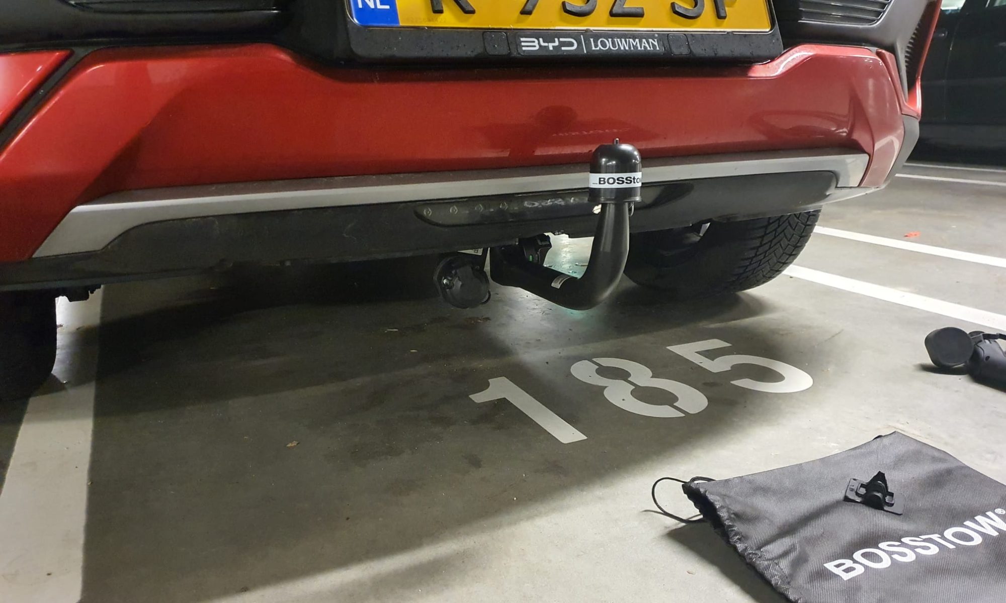
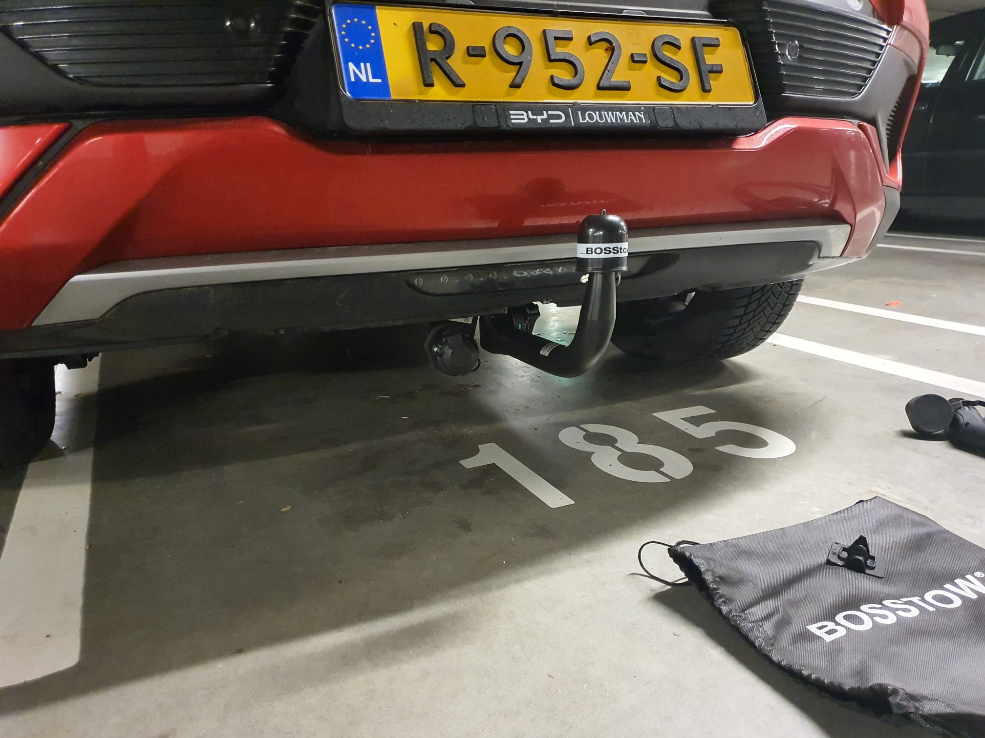
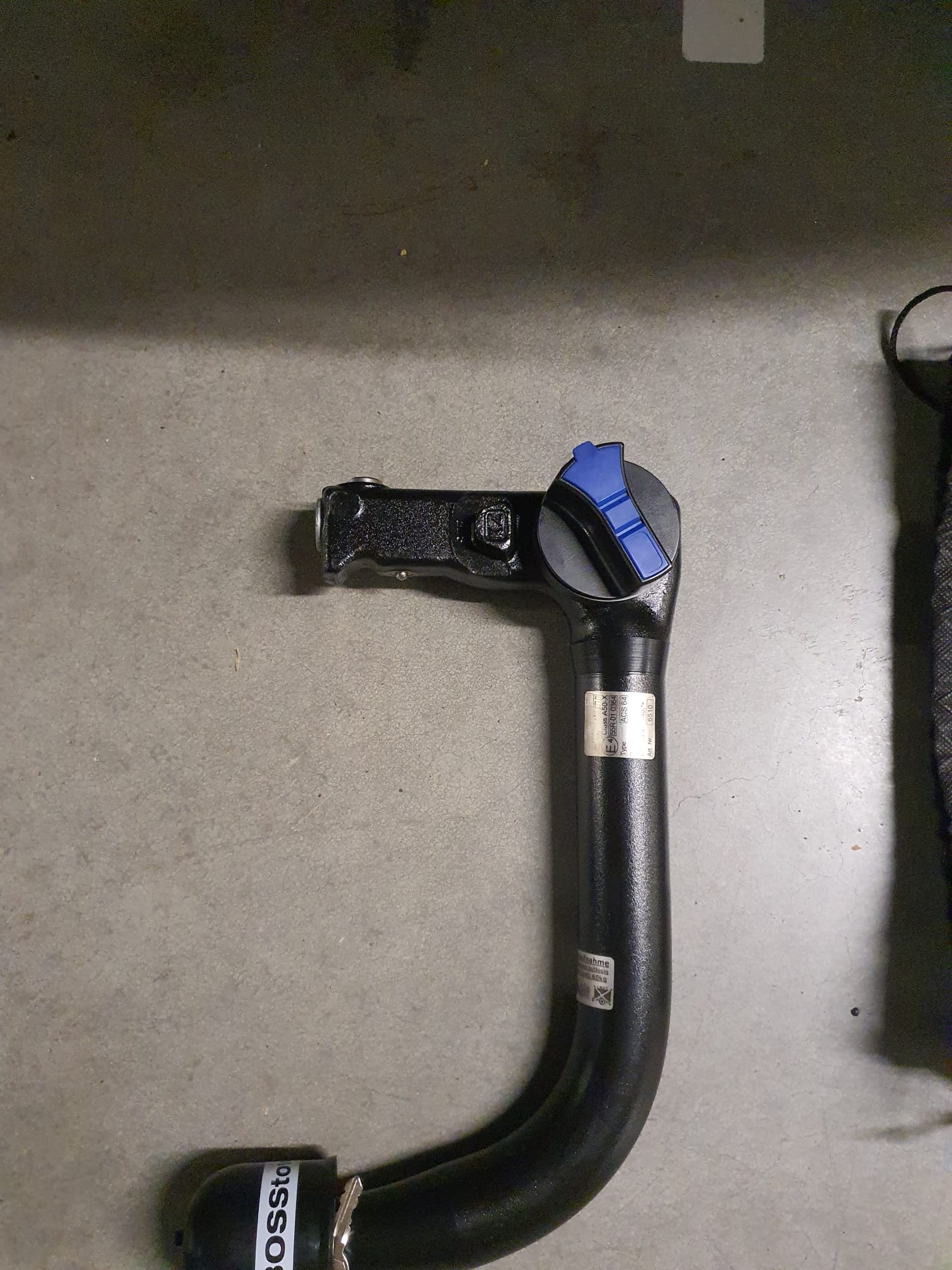
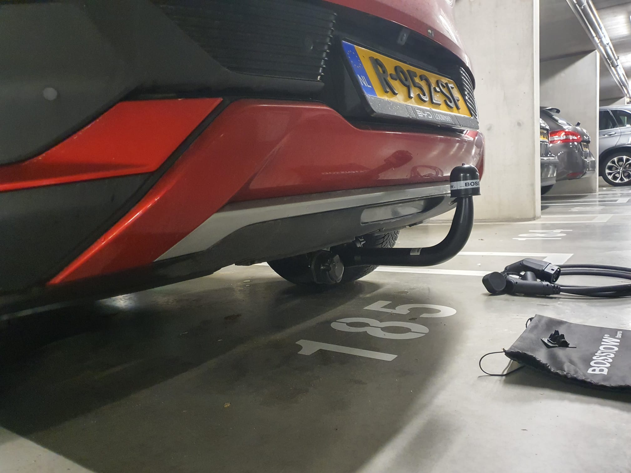
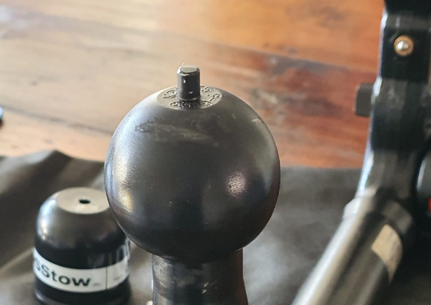
BYD Atto 3 tow bar

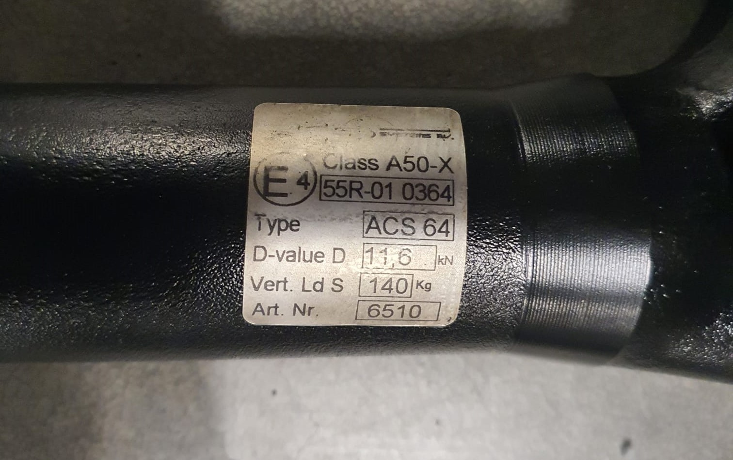
In the Netherlands, Burghof trekhaken has developed a detachable lockable BOSSTOW tow bar for the Atto3, only to be used for carrying bikes or a towbox on the ball of the bar.
Not to be used for pulling anything.
UPDATE 2023-05-13: Message received from an Atto3 driver from Belgium that the BYD Ato3 will definitely NOT get homologation for a towbar, neither in NL nor in BE. This probably means that there will be no homologation for the tow bar anywhere in Europe. In Belgium there will also be NO homologation for a tow bar for a bike carrier. In the Netherlands, the regulations are not entirely clear, but tow bars approved according to Tüv (DE) standard are tolerated as tow bars for bike carriers on cars without tow bar homologation.
The tow bar can be taken off vertically and the cable box can be pushed up, so nothing reveals the presence of a tow bar installation when is has been dismounted.
Available for deliveries end of April 2023.
Can be ordered at Burghof trekhaken.
I have the prototype mounted on my car (2023-3-30):
                                                                                                                                                                                                   .
Interestingly enough, as expected I have a German Tüv allowance paper that came with the pulling bar that states that the towbar is intended only for mounting a bike carrier or a towbox with a max vertical pressure of 60kg.
AND you should know that the BOSSTOW towbar hitch as a whole is approved for pulling 11.6 kiloNewton (1160 kg)  which is more than the Atto3’s (in NZ) allowed 750kg.  The maximal  vertical pressure that the BOSSTOW hitch can handle is  140 kg.  This hitch is well-oversized which is OK by me.
I am not worried at all about the sturdiness of the hitch, it appears to be a strong enough construction that is capable of handling much more than I will ever need.


Posted on 11 March 202323 April 2023

Super large LED clock with WS2812 LEDS and Arduino nano+3231 clock module

https://jantecnl.synology.me/wp-content/uploads/2023/03/WhatsApp-Video-2023-03-11-at-20.16.55.mp4

FASTLED_clock_ALL_feed_V6_2023_01_22_FINAL_ONLY_CLOCK DOWNLOAD ARDUINO PROGRAM FILE

Posted on 19 February 20232 March 2023

Starter motor Traction Avant (12 Volt) repair with new carbon brush

And suddenly the Traction Avant wouldn’t start.

It had been struggling a few times, as if the battery was dead but it was nicely full.

And suddenly just a click instead of a running starter motor.

I have a Paris-Rhone 12V ID starter motor in my Traction Avant

-which fits the flywheel of my long stroke Citroën ID (DW) engine once mounted in the TA.

See photo below, The starter motor is under the exhaust manifold of this engine, in the same original location as on the Traction Avant 11D engine.

You can also remove the starter motor from underneath, but putting it back in is really easier from the top. Unless you have a bridge, of course.

As a possible emergency measure I mounted the original Traction Avant 6Volt starter motor, but it does not engage the Citroën ID flywheel. So quickly removed again.

The repair:

When you remove the two M6 nuts and locking plates on the back of the 12 Volt Paris-Rhone starter motor, you then slide the aluminum back including both carbon brush holders off a bit.

The carbon brush on the armature side (+) was the culprit, it was worn down pretty crookedly. It seems that one of the connecting wires had just a little too little space to allow the brush to move straight.

I then measured and ordered the carbon brushes.

The starter motor is otherwise in fine condition, the rotor and collector also look good.

The carbon brushes are the same size (about 7×17.8 mm) , and they have the same kind of soldered wire connections.

In the end it was only necessary to replace the carbon brush on the armature side, the other carbon brush which is on the minus is barely worn.

Above with the pre-soldered wires already mounted, and below AFTER soldering, after mounting the carbon brush in the carbon brush holder.

The collector of the rotor was completely flat so having it reworked in my lathe  didn’t seem to make sense.

After cleaning and assembling it, I first tested everything using a small battery from my motor bike, gave everything a little grease, secured the back with the 2 locking plates and reinstalled the starter motor in the TA.

Immediately started and everything OK again!

Posted on 27 January 202330 July 2023

BYD Atto3 -Spare tire in the trunk

Above the original filling of the space at the bottom of the trunk of the Atto3 is shown, with a.o. the tire ‘repair kit’.

I like to drive around with a spare tire because I drive on construction sites quite often, and so far I have had 2x tire damage because of that.  And such a damage is not always fixable with a fluid repair kit.

My new spare is a home-bringer also used on a Toyota RAV4 : R17 165/80/17 tire and a 5X114.3X60.1 rim with the same circumference, pitch and center hole as the BYD Atto3.  The RAV4 weighs a bit more than the Atto3, so it should be fine.

At the bottom of the trunk the available space for a home-bringer is only 57 centimeters in diameter for a spare tire.

This means that the spare tire will be slightly higher mounted, on a mounting bracket.  Under the spare tire there is then room for the jack and the likes.

The trunk cover had 2 positions, and this shelf at the bottom of the trunk therefore only comes to one possible mounting depth, i.e. in the highest position.

So- that’s how I positioned the spare tyre (from a Toyota RAV4, 17 inch) in the boot of the car.  Not the nicest way but it works OK. The shelf that comes with the car can be positioned in the upper position no problem.  I added a hydraulic mini jack and a wheel bolt wrench, since this was not part of the car’s accessories.

To hold the tire down, I made a mounting bracket from square iron tubing 20-20-2mm with 3 holes: 2 to tie it with M6 nuts to 2 of the 4 already available threaded M6 bolts and 1 hole in the center of the square stock to carry an M10 bolt going UP with a washer and a wing nut. The M10 bolt goes through 1 of the boltholes of the rim.   I welded the M10 bolt in the center of the square steel and made the rear part almost flush with the square steel.  Then, I mounted the bracket down on the floor of the boot with 6mm tubed M6 IKEA nuts that I had lying around from an old double children’s bed.   These nuts are about 15mm in length with a large flathead on top and an Inbus insert in the top.  This is ideal, because the M6 steel bolt-ends that stick up from the boot are only around 18mm in length and don’t stick through the 20mm square stock.

BTW: I shortened the 2 not-used standing M6 bolts to the height that they just carry one M6 nut each, might be useful in the future.

After the spare tire was mounted and secured with the washer and M10 wing nut on the bracket I used the bag that came with the removable part of the pulling rod to store all loose components like the puller for the plastic boltcovers that are mounte in the wheels and o on.  This is placed in the inner part of the spare tire.

Unfortunately, I forgot to take some pictures of the setup of the spare tire mounting bracket, will do that when I can and present this here, later!

Posted on 27 November 202223 April 2023

Xmas star door/ window hanger Arduino nano and WS2812 LEDS with LDR

https://jantecnl.synology.me/wp-content/uploads/2021/08/20201213_arduino-nano-Xmas-star-and-Ws2812-LEDS-1.mp4

The latest arduino code WITH LDR is HERE:

The LDR is to be soldered between A0 and GND.

The data output is D5 and this must be connected to Data-in of the WS2812 (B) string.  5V and GND goes to the power source, which is also connected to the Arduino Nano.

The STL file for the star parts is HERE.  Print this x5 in semi-transparant white.

The small Xmas- star measures 50cm in diameter from left- tip to right-tip. I printed it with glow in the dark ABS, white.  It glows in very faint green, it is just enough to glow a little and keeps your eyes focused on the star when it is not lit.

If you make the star legs watertight with silicon sealant, the star can easily be attached to an outside wall, door or fence.

ou can use a long 3-wire cable between the Nano and the Xmas star to keep the electronics mounted inside the house and the star outside, or as I did: hang the star inside, in front of any window.  I have the star hanging in my front door window, which gives amazing effect due to the non-transparant glass.

The programming can be altered to make the light effects behaviour any way you like.  I usually have a non-stroboscopic fluent scene running.

You need to print 5 star points, feed the LEDs through them and then have the wires come out somewhere.  You can glue the points together with hotglue or transparent silicone sealant after assembly and testing.

If you don’t have the Arduino IDE yet, download the app from the Microsoft website (Arduino IDE) nor from the Arduino cummunity forum.

Make sure you download my Arduino code and open it with the Arduino IDE APP. Probably the APP will have to move the arduino INO file to a new directory but that should do the trick. If not, start the Arduino app, open my code in notepad and copy/paste it as fully new code into Arduino:  Replace the example code that automatically opens when you open the Arduino program/app with my code.  Save it and rum it to see wether you need to add any library.  For adding libraries, find general help in the Arduino forum.  In my code, you can find the names of the required libraries.

undefined

In the Arduino IDE select the right microprocessor (Arduino Nano).  Then select the correct processor version (large or small memory) and the old or new bootloader.  These choices depend on the type of Nano you bought or still had lying around.  Then you choose the right port (USB) for your Nano.

To test if you have connection between IDE and Nano , you can ask if the Arduino IDE can read your Nano.  Only then you can start loading the Nano with the complicated program.

The BIG 70cm width 5-pointed star with thin hollow legs to put the WS2812 LED string through. AND an integrated tube to put the wiring through

https://jantecnl.synology.me/wp-content/uploads/2021/08/5-pointed-hollow-big-star-for-WS2812-LED-string.mp4


The Arduino programming file is HERE.

The latest arduino code WITH LDR is HERE:

The STL file for the big star is HERE.

Afterthougts: I also made circular designs, dual oval crossing designs and a lot of designs that I tied to existing shapes like a steel star, some Xmas animals and so on.  The light design I made varies per application,  A star typically requires a specific design due to its shape.  A cicular design needs more of a scattered design and a straight string or a balcony-wrapped design all require specific patterns of LED programs.

I will also try to implement an auto-scanner in the setup part of the code to identify the number of LEDS that is used, since this is required to get good petterns to the string used.  (set NUMPIXELS automatically)

Posted on 25 November 202225 November 2022

BYD Atto 3- under the bonnet

My BYD Atto 3 has been delivered on November 14th 2022, and I took some pictures today under the bonnet:

Posted on 20 November 20226 April 2023

BYD Atto3 on all-weather tires Bridgestone 235/50 R18 101H XL (GAN) Weather Control A005

Suddenly it is snowing in the Netherlands, barely a week after my BYD Atto 3 was delivered on  2022-11-14th.  The car came with fine Continental summer tires:


But I don’t feel like changing tires twice a year so it will be all-weather tires to match the car.

After some research I chose all-weather tires with the same size as the summer tires the Atto3 came with: 235/50/18.

Because of the weight of the car (1725 kg), solid tires are needed, not so much because of the maximum speed of 160 km/h.

So it became these all-seasons tires:  Bridgestone 235/50 R18 101H XL (GAN) Weather Control A005.  The new tires will come on the original rims and the Continental summer tires will go into storage for the time being.

The energy rating of the Bridgestone all-weathers comes to class A, rain and snow resistance comes to B and noise comes to 72dB.

These tires have a snowflake as a mark on the tire so at least you can also drive them in Germany in winter.

After the installation (2022-12-13th) our experiences are:

Well, the handling of the car improved a lot on icy roads, as was to be expected.

These all-weather tires are behaving a lot like the original tires, prime quality as well with the f=difference of good grip under below-zero degrees (C) temperatures on wet or iced roads.

Also, under such conditions it makes a great difference when accelerating a bit more than niormal, then the true difference can be experienced.

All in all, I am very pleased with the Bridgestone 235/50 R18 101H XL (GAN) tires, also because I could not detect any change in average power usage after the switching of the tires.

Posted on 16 November 202226 November 2022

BYD Atto 3 delivered 2022-11-14th!

I am very happy with the Atto3 from BYD,  that came delivered 2022-11-14 within 1 month after ordering!

Most  pictures are taken in the parking garage where I have my own charging connection, from Blue Current.

This allows me to top the car off daily, and every morning I start fresh with 420 km range!

https://jantecnl.synology.me/wp-content/uploads/2022/11/WhatsApp-Video-2022-11-16-at-17.12.32.mp4

Posted on 9 November 202226 November 2022

Charge connection via extension cable and connection box to wallbox copper

I have a wallbox copper charging station for an electric car with load balancer that I use both in the garage and at the front of the house with 11kW charging via power.

At the front of the house is a public sidewalk and parking is available to all.  Usually there is no place to park the car out front when I get home.

If I want to charge in the garage I have to park the old car outside first so the EV can get in to charge.  Because I always work from home during the day I can always park the car in front of the door at those times to charge. But the municipality of Woerden has included in its existing 2017 decision on its charging policy, among other things, that it is not allowed to lay a charging cable over the sidewalk.  Other options for home charging such as a charging chute in the tiles or other solutions are also not allowed (yet). The starting point of municipal policy is public charging from user-driven applications.   I have done that through an application to the party chosen by the municipality, and after 9 months it has still led to nothing.  There are all kinds of reasons such as the full power grid and going through objection procedures that make building public charging points not very fast. but at my home it was settled with Stedin within 2 weeks.  Now I can just charge at home with 11kW.  But municipal policy does not allow that on public roads.

So I charge publicly when I can or in the garage.  I hope the municipality, under pressure from its residents, will eventually allow alternatives to use charging cables safely over the public sidewalk.  There is quite a bit of political pressure to move on this.  The existing charging policy of the municipality of Woerden predates the time when EVs are available in growing numbers, so it is time to change this in terms of vision anyway.

As is now clear from user experiences, the purchase of EVs will be significantly stimulated when home charging solutions become available including solutions for connecting your EV to your home charger via public space. This is already in place in a growing number of municipalities, albeit mostly on a temporary trial basis.

In order to charge the EV at home, I have already implemented the following:

First, I replaced the meter box with a 3-phase meter box with circuit breakers.

Then I also laid a power cable to the garage, including the connection between wallbox copper on the one hand and load balancer and internet on the other, both via their own CAT-6 cable.

Then I made a box on the front wall with an extended wallbox copper connection point.

From the connection box the cable can be laid to the car.  The cable mat below will be laid over the cable.  The mat has a hollow space in the middle, lengthwise so the cable can lie neatly under it.


And so the above wallbox copper I can now mount::

1) OR in the meter box when the car is in front,

2) OR in the garage when the car can load on “own ground” in the garage.

Posted on 6 November 20226 November 2022

Harley-Davidson-livewire-electric-motorcycle-spotted in Amsterdam as a Zündapp ??, 2022-11-05

Yesterday I spotted a Harley Davidson electric bike, covered by a Zündapp sticker!

It was parked next to a canal in Amsterdam-Old West.

Above is the original version shown of an HD livewire!

I took some pictures of the Zündapp and they are shown below:

The bike is registered as an HD Livewire in the Netherlands, from 2021-05-14th at 0.42 kW/kg and at 60kW.

Weight is registerd at 143 kg drive ready.

Max speed as registered is 177 km/hr.

Catalogue price is registered at Eur 34.000.


Posted on 29 October 202218 May 2025

EV charging across the public pavement with flat EV cable mat (C) Jantec.nl

UPDATE 2025-05: We now have a flat 2.5mm2 x6 cable::

In this post we will describe our solution for charging Electric Vehicles from your home across the public pavement when using our super thin EV cable mat with rubber slabs.

Due to the rapidly growing ownership of electric cars, and the fact that roughly 60% of the Dutch population can not charge their car from within their own property, charging across public pavements has become an issue.

25% of Dutch City Councils is involved in pilot projects about all sorts of solutions to get the private energy-infrastructure used for charging ones own EV.  But- there is no general regulation for this.

And- you really don’t want to get all sorts of different solutions for putting charging cables in the way of pedestrians, especially not when these solutions leave something in the way after it has been used. Certainly you don’t want to put anything in the way of people with baby walkers, playing children, people with disabilities, elderly or people that use mobility walkers.

Numerous solutions have been tested and there is not one solution that fits all.

Most promising appears to be the solution of a pavement gutter in which the charging cable can be pushed in, during charging.  But- it has also proved to be difficult in practice since this only works well if no-one interferes with its usage.  If the cable is pulled out, it will be in the way of everyone that needs to step over it.

In my mind, a simpler solution will be required by thinking unconventionally,  typically out of the non-electric box

The problem is that we want to charge the car’s battery from our existing solar panels, we then want to make use of the EV’s battery for our home aplliances through the Vehicle to Load feature during the period that there is not enough sun to use the solar panels.  Then, we can really close the energy circle without additional investments in home batteries and so on.  That is what this is all intended for.  Multi-use of the EV’s battery and of the available solar power.

BUT- this can only work with the EV’s battery connected to your home.

And the public pavement needs to be crossed.

One of the possibilities to do this could be by constructing a charging/Vehicle To Load cable that is flat enough to behave as a doormat on the pavement.  This mat must be flat enough to not cause any interfecerence for pedestrians, walkers and so on BUT it must be tough enough to keep its form and electrical characteristics during its use.

In my view, the flat cable mat should have flat start- and ending docking cables,  reshape to normal round cables and EV charging connectors, connecting to the EV’s charging port and the other end to the charging point at the home.

EV charging from A/C has a maximum power of 11kW, 3 phase 400 Volts.

The current will be 16 Ampères x3 lines and per line at least 2.5 mm2 is required.

Some insulation in between the wiring is regulatory required.

For the 2 management wires we will also use round wires.

We will need 5×2.5mm2 and 2 control wires, a total of 7.

Standard flat elevator cable will be used of 7×2.5 mm2, see the below picture, the lowest one.

And- the mat will need to be wider than this, since we can use this to bring the height (thickness) back to 2-3 mm at the end of the mat’s side.  That gives the look and usage experience that the EV cable mat is hardly in the way of the walking/rolling path.


Our ‘patent pending’ design of the  Jantec.nl  EV charging pavement cable mat:

Total width of the EV pavement cable mat is around 40 cm

The slab has the behaviour of a normal doormat. We will pour our rubberized mat around the center EV-cables part.  The rubber will protect the cables and will also keep the EV cable mat flat on the pavement.

Cable center part is only  1,5-2 cm wide and  only 5 mm high (thick)

The EV cable mat will become available in lengths of 1, 1.5 and 2 meters.

At both ends the copper wires are bound into a regular round cable with 2.5 meters of cable, including regular Mennekes a male and a female charging connector.


NB: The product is under evaluation 2022-10-29.

Pricing is yet unknown, but will be above Eur 300 per set.

For the  time being,  I used  my old rubber mat that has a cut-out already, although the cable is clearly visible through  he mat.

The flat cable is working much better!!


Posted on 10 October 202210 October 2022

Rijksmuseum Amsterdam, September 8th 2022

R0000145
R0000146
R0000149
R0000152
R0000154
R0000155
R0000156
R0000158
R0000159
R0000160
R0000161
R0000163
R0000164
R0000165
R0000166
R0000167
R0000168
R0000169
R0000170
R0000171
R0000172
R0000173
R0000174
R0000175
R0000176
R0000177
R0000179
R0000180
R0000182
R0000183
R0000184
R0000185
R0000186
R0000187
R0000188
R0000190
R0000191
R0000192
R0000193
R0000196
R0000197
R0000201
R0000203
R0000205
R0000215
R0000218
R0000221
R0000228
R0000230
R0000232
R0000233
R0000234
R0000235
R0000238
R0000239
R0000241
R0000242
R0000243
R0000244
R0000245
R0000247
R0000249
R0000252
R0000253
R0000254
R0000255
R0000257
R0000258
R0000259

Posted on 8 October 202229 January 2025

TOYOTA LC80 CRAWLER SCALER 1 to 10 scaled

Just bought me this 1 to 10 scaled Toyota Land Cruiser 80 on a Scaler / Axiale chassis, including engine and steering servo.

I ordered me an RC controller and-receiver, battery, charger, motor controller and so on from Amazon.

Works all fine!!

Posted on 6 October 202211 September 2025

E3D toolchanger 4xHemera direct drive first 4-color PLA benchy & 3D-world

https://jantecnl.synology.me/wp-content/uploads/2022/10/E3D-toolchanger-first-benchy-4-colors-Hymera-direct-drive.mp4

The bow of the benchy , the white right part at the bottom sags a bit.

The solution was to set the bed temperature at 10 degrees lower.

So;  I now start with 60 degrees and after the first layer the bed temp goes to 50 degrees.

In addition, I flipped the benchy 180 degrees so that the cool air on the left side cools the bow better.  Now it turned out absolutely beautiful!

Printed with 0.2 mm layer height and 120 mm/s!

Not perfect yet but we’ll get there!

E3D toolchanger: Tuning the tool pickups with reprap global variables and macros assistance

E3D toolchanger upgrade: X-and Y- axis homing switches installing and configuring

Building E3D coreXY 4-toolchanger 3d printer

Toolhead stepper fault and solution

Custom E3D toolchanger Dock adapter plate

Calibrating E3D coreXY 4-toolchanger 3d printer

Posted on 28 September 202211 September 2025

E3D toolchanger: Tuning the tool pickups with reprap global variables and macro’s assistance

After I installed the homing switches for X and Y on the E3D toolchanger, I finally had a decent starting point to get the tools pickup and parking tuned.

Originally, I used sensorless homing but this caused changing offset values of the X- and Y positions of the machine. So the tools could not be picked up or brought home consistently after a reset.

Now, everything works fine and the X-Y values don’t change anymore after a reset.

What I did was to first make some macros for a one-off setting of the X and Y postion of the 4 Tools for the toolhead’s positioning.  If you don’t do this, you have to change all X values manually in 8 macro’s every time you want to change the value of X.

This was done with a number of global variables.  After defining these in a macro, they need to be called before using them.  In Config.g, I made a reference to run  the macro of the globals.g macro so it runs every time you boot the Duet.

In config.g, after the Tool definitions I added the M98 code to start the global definition of the used variables:

M98 P”0:/sys/globals.g” ; Make global variables in this globals.g macro

This macro file looks like this in my case and please be aware that the actual variables will differ per machine, but this may give you a starting point:

global T0_X_dock=-12.3 ; X-Parking position of Tool 0
global T0_Y_dock=225.2 ; Y-Parking position of Tool 0
global T1_X_dock=80 ; X-Parking position of Tool 1
global T1_Y_dock=225.9 ; Y-Parking position of Tool 1
global T2_X_dock=212 ; X-Parking position of Tool 2
global T2_Y_dock=226 ; Y-Parking position of Tool 2
global T3_X_dock=304.7 ; X-Parking position of Tool 3
global T3_Y_dock=225.4 ; Y-Parking position of Tool 3

The tfree 1-3and the tpre 1-3 files will then be like this for T0, and you can make the others by just fulling in T1 , T2 or T3 where it now states T0:

; tfree0.g
; called when tool 0 is freed
G91
G1 Z4 F1000
G90
;Purge nozzle
;M98 P”purge.g”
;Move In
G53 G1 X{global.T0_X_dock} Y150 F50000
G53 G1 X{global.T0_X_dock} Y200 F50000
G53 G1 X{global.T0_X_dock} Y220 F50000
;G53 G1 X{global.T0_X_dock} Y{global.T0_Y_dock} F1000
G53 G1 Y{global.T0_Y_dock} F1000
;Open Coupler
M98 P”Coupler – Unlock.g”
;fan off
M106 S0
;Move Out
G53 G1 {global.T0_X_dock} Y175 F50000

; tpre0.g
; called before tool 0 is selected
;Unlock Coupler
M98 P”Coupler – Unlock.g”
;Move to location
G1 X{global.T0_X_dock} Y200 F50000 ; was X-10.5
;Move in
G1 X{global.T0_X_dock} Y220 F50000
;Collect
;G1 X{global.T0_X_dock} Y229.2 F1000 ;was f2500
G1 Y{global.T0_Y_dock} F1000
;Close Coupler
M98 P”Coupler – Lock.g”
;WARNING! WARNING! WARNING! WARNING! WARNING! WARNING! WARNING! WARNING! WARNING! WARNING! WARNING! WARNING!
;if you are using non-standard length hotends ensure the bed is lowered enough BEFORE undocking the tool!
G91
G1 Z10 F1000
G90
;Move Out
G1 X{global.T0_X_dock} Y150 F10000; was 4000

And I made some macros for checking where the toolhead is positioned, right in front of the tools T0-T3:

; fit_T0.g
; called to fit the Tool just in front of the dock
G91
G1 Z4 F1000
G1 Y-10 F2000
G90
G53 G1 X150 Y100 F20000
;Move In
G53 G1 X{global.T0_X_dock} Y150 F10000
G53 G1 X{global.T0_X_dock} Y200 F10000
G53 G1 X{global.T0_X_dock} Y220 F10000

If you want to check wether you made the correct changes to globals.g, be aware that the new values in the globals.g variables macro will only be read when you reboot.  [If you want to redefine the values in any other way without rebooting, you will need another type of call function.]

Posted on 28 September 202211 September 2025

E3D toolchanger upgrade: X-and Y- axis homing switches installing and configuring

My E3D toolchanger appeared to have some small inconsistencies in homing X and Y.

This became apparant after I tried to tune the exact positions of the tools pickup, after having homed.

Every time it was tuned, it worked well and the next day it was just a bit off. Then I retuned it again, and after a day it was off again.  Not a lot, but just 0.1 mm or a bit more.  But it did cause problems with the toolchanges.

So- after reading a bit I found that others had this problem as well and produced a solution: Just put in a couple of good X- and Y homing switches!

I even found the to be printed 3d-parts for mounting these switches. Thanx for this, folks!

The switches are the same type as for the Z-switch.

X-axis end switch

Y-axis end switch

I printed the mounts in PETG carbon on my Prusa mini and mounted  both switches on the E3D toolchanger.

After this, I amended config. g and the homing files, please see the rest of my post for this:

CONFIG.G CHANGES

; Endstops
M574 X1 S1 P”xstop” ; X min active high endstop switch
M574 Y1 S1 P”ystop” ; Y min active high endstop switch
M574 C0 ; no C endstop
M574 Z0 P”nil” ; no Z endstop switch, free up Z endstop input as Z endstop switch. (I changed  this part for correct working with RRF3.3+)

NEW HOMING FILES:

; homex.g
; called to home the x axis

M98 P”homey.g” ; Home Y always before homing X

G91 ; use relative positioning

G1 H2 Z3 F5000 ; lift Z 3mm
G1 H1 X-400 F15000 ; move left 400mm, stopping at the endstop
G1 X5 F15000 ; move away from end
G1 H1 X-400 F2000 ; move left 400mm, stopping at the endstop
G1 X2 F2000 ; move away from end
G1 H2 Z-3 F1200 ; lower Z

G90 ; back to absolute positioning

; homeall.g
; called to home all axes;

M98 P”homec.g” ; Home C (ToolHead)

M98 P”homex.g” ; Home X

M98 P”homez.g” ; Home Z

G1 X150 Y-49 Z20 F15000 ; Park

; homey.g
; called to home the Y axis

G91 ; use relative positioning

G1 H2 Z3 F5000 ; lift Z 3mm BED DOWN
G1 H1 Y-400 F15000 ; move to the front 400mm, stopping at the endstop
G1 Y5 F15000 ; move away from end
G1 H1 Y-400 F2000 ; move to the front 400mm, stopping at the endstop
G1 Y2 F2000 ; move away from end
G1 H2 Z-3 F1200 ; move Z BED UP

G90 ; back to absolute positioning

Z homing did not change and remains as is:

; homez.g
; called to home the Z axis
M98 P”Coupler – Unlock.g” ; Open Coupler
G91 ; Relative mode
G1 H2 Z5 F5000 ; Lower the bed
G90 ; back to absolute positioning
G1 X150 Y100 F50000 ; Position the endstop above the bed centre
M558 F1000 ; speed to 1000
G30 ; probe x 1
M558 F300 ; speed to 300
G30 ; probe x 1

Posted on 16 September 202223 September 2022

Managing power consumption at home with AR12DX metering modules / load switches / priority switches in the distribution cabinet

Please note that this post is valid for the situation in the Netherlands with the Dutch power grid for consumers.

The situation in the Netherlands and most of Europe is that the deliverd power to regular power outlets is 230 Volts @ 50 Hertz.

A 3-phase power connection is 3x 400 Volts, 50 Hertz.

After my installation of two 400 Volt power groups, one for charging the electric car and one for the instantaneous water heater (for showering without gas), I ran into a problem with the power consumption of a  Dutch standard 3×25 Amps house connection, as is standard delivery when 3×400 Volts is required.

For charging the car, an easy solution was to install a load-balancer in the meter box or next to it with a link to the smart power meter of the grid operator (all depending on the chosen brand of charging box/pole) .  Then the load-balancer communicates to the charging station how much power is available for charging the car.  Always good.

For the flow-through water heater power group, it was more difficult. This unit uses 11 kW divided over 3 phases. Since we are also cooking on a 2 phase-connected stove and  we have also ordered a heat pump for heating the house, the load per phase might be more than the available 25 Amps or 5750 Watts.  Times three is then 17250 Watts.

Of course, you can agree on all kinds of things with your co-occupants, such as not showering when you cook or when the heat pump turns on.

But to make sure your consumption is not suddenly too high, you can also create a technical solution that fits into your existing meter box.  Perhaps the necessary switching modules themselves will fit into your existing distribution board.   In my case it all fitted OK, because I recently installed a new distribution board for the 400V power group to charge the electric car,

The load balancer for the EV

The required modules that you can mount in the meter box are measurement modules that, when you have more than a settable value of power consumption of a particular group, can energize a switching contact.  Through that contact you can then control a relay that in my case I placed between the power connection of the flow-through boiler power group.

That relay, which is included in the water heater connection, ie of the type Normal Connect, so in the inactive position the instantaneous water heater is simply energized.

If at least one measurement module activates a contact, the relay in the boiler connection is activated and turns the instantaneous water heater OFF.

Technische_fiche_AR12DX (sorry, in Dutch…)

I have included in the 3 groups L1, L2 and L3 each 1 piece AR12DX switch/measurement module and there I have successively connected the following frequently used ‘with prio’ groups:

Dishwasher with electric kitchen faucet (1-phase instantaneous water heater);
Living room, second floor washer and heat pump dryer;
Second cooking group (our 2-phase cooktop can also operate on 1 phase).

These 3 groups always just stay on (it’s called “with prio” in this case), they just determine that the shower-flow water heater cannot operate if a certain power level is exceeded on any of these 3 groups.

Namely, the measuring/switching modules are adjustable for waste hysteresis (set to 0 for this situation with ordinary contact relay) and current.  The current at which the contact is activated is adjustable.  This is especially nice with group 2) because with just watching TV or lights on, you still don’t want the switch to flip.

I set the current of the second measuring/switching module to 5 amps, of number 1 and 2 the current setting is at 1.5 amps.

I am still looking for a 3-phase NC SSR, 400V 40A.  When I have it I will replace the relay.  That relay works very well but it is also very loud.  The meter box is in the hallway closet against the kitchen.  The group box sits on a wooden board on the plaster wall on the other side of the kitchen and you can hear the relay switching very well.

The schematic of the 3x AR12DX measure/switch modules as I implemented it: (still in draft and in Dutch but OK)

So far everything is working fine, and these first weeks all went fine!

Below the 230V power groups and phase arrangement is shown (in Dutch)


Posted on 10 September 202212 September 2022

Reduced usage of natural gas – Electric supplementary heating or a heat pump installation?

In this post we’ll describe our solution to reduce our domestic natural gas consumption by at least 50% in the coming winter ’22-’23.

The original plan:

  • stop heating part of the house;
  • per room where necessary additional heating with electric ceramic 500 watt wall plug heaters with thermostat;
  • Downstairs in the living / cooking room primarily with an LPG-fired potbellied stove to heat the room, possibly supplemented by 2 pieces of ceramic heaters, with thermostat.

LPG gestookte potkachel met katalysator, zuurstofsensor enz.

thermostatisch geregelde elektrische mini bijzetverwarming 500 Watt

Second thoughts..

When you start calculating with energy values and electricity prices you quickly find out that a solution with electric supplementary heating is not very feasible.

Electric heating is just not very economical because -despite the high energy prices- it is still twice as expensive to heat with electricity compared to heating with natural gas (in a nutshell: 1 m3 of natural gas at Eur 4 per m3 provides as much energetic energy as 8 kWh of electricity at Eur 1 per kWh. And 4 Euro is half of 8 Euro).

The heat pump installation instead of the ‘old’ natural gas powered central heating system

If energy prices remain as high as in August 2022, we will as soon as possible install a complete electric heat pump system with split units.

We will then also completely abandon the natural gas-powered central heating system, because we already have a low-temperature central heating system with underfloor heating.

And that’s extra handy when using a heat pump system:

Split outdoor unit (left) and the indoor unit (right) with 12.6 kW heating capacity for an all-electric heat pump system without gas-fired C.H. support.It’s not going to be a hybrid system, with the gas-fired central heating system staying put when it gets colder than about -5 degrees.

You’ll never get rid of the gas, because you’ll just have a heat pump system that’s too small to continue without the central heating support if the gas is ever turned off, or you just want to get rid of it.

With a hybrid heat pump system, the gas-fired central heating boiler has to intervene when it gets too cold (outside below -5 degrees) or if you haven’t heated up for too long and it therefore takes too long without the intervention of the gas-fired central heating boiler before it gets a little warm.

Up to 6-8 kW there are hybrid systems that work together with the existing central heating boiler.  If you want a system that can replace the gas-fired central heating boiler, we need to calculate exactly what heat output we need.

The existing gas fired HR boiler is a Nefit smartline HRC24 CW4.  It has a maximum output of 24kW.

According to the experts, our heat pump must have a SCOP value of at least a factor of 5.

This means that the electrical energy that you put into the heat pump system for the transport of energy ensures that five times more energy is delivered to (hot central heating) water at a maximum temperature of 55 degrees Celsius.

This is due to the operating principle of the heat pump, just like condenser (washing) dryers and air conditioners with heat pump principle.

When it gets colder outside, the efficiency of the heat pump in terms of heating does decrease.

So, for a heat output of 24 kW, you need a heat pump system that can deliver 24 kW of energetic water heat.   And that system uses 24/5 = about 5 kW of electricity at a SCOP value of 5.

Because such heat pump systems are based on standard connections to the 230Volt mains supply with a 16 Ampere connection rating, the common heat pump systems are usually somewhat smaller than 24kW.  The value we selected for the split system is 12.6 kW.  This keeps the electrical power consumption well within the 16 amp standard of the connection value of the electrical groups in our house.

It could be that in case of severe frost we have a problem to really heat up the house, we take that for granted.  When we talk to the installer/supplier about the heat pump system we’ll also have them calculate whether a 12.6 kW system will do. And if necessary, we will opt for a slightly larger system.

The split outdoor unit will be placed on the flat roof, somewhere between the solar panels, or on the sloping roof, just below the skylight with special sloping roof brackets.  It has to be a quiet model anyway, which may be difficult because these outdoor units are never quiet.  So it also needs a night mode with low-speed pump and fan operation.

We might also install an intermediate boiler next to the indoor unit, so there will always be a supply of hot water.  If we can take a shower with that, we can turn off the instantaneous water heater and only use the instantaneous water heater when it gets too cold outside.

The cost is about 7500 Euro for this installation and we are willing to pay that.  You will also receive a 2500 Euro subsidy in retrospect.

The insulation of our terraced house is also excellent, and we will be satisfied if the heat pump works in such a way that the first floor can be heated to 20 degrees. We want to keep the bedrooms at an average of 15 degrees.  The second floor goes on the anti-frost mode…

And I’m not even thinking about the payback.

We have to get rid of the gas in any case, and our C.V. boiler is now 20 years old, all kinds of things have been replaced and it works fine again every time after the repair.

But replacement is coming.

And whether that is useful, given the desire to get rid of gas?

Better to do it right the first time.

Cooling with the central heating system and the heat pump is also possible.

Incidentally, I want a heat pump system that can actively cool in summer.

In principle, this is quite possible with an all-electric heat pump system.

The radiators will then become cold.

That seems like a very useful option, I’m curious how my thermostatic valves would cope with that!

Our household’s heating situation

Our house still has, among other things, a floor heating system directly fired by the central heating system on the first floor and insulated glass on all floors. The cavity walls are still without insulation (we should do something about that but the wall surface is so small compared to the windows that the effect of wall insulation is probably not very big, according to the experts…) and we have an attic that is not used as a bedroom.

So we are not going to heat the attic in any case, and that makes a difference.

And we already cook electrically, the oven is also electric.  The kitchen tap is electric, and the shower water (and sink) are also heated electrically via an 11kW instantaneous water heater.

Heat pump or air conditioning system?

An air conditioning system would also be an option, of course, as this also works on the heat pump principle. At the moment, the only air conditioning system that is quite OK in terms of efficiency and affordable in terms of installation is a multiple air conditioning system with one unit outside and several inside.

You must have an installation with a COP value above 5 because then you also have a bit of efficiency when it gets cold if you also want to heat with it.

Such a multi-airco system with 4 indoor units and 1 outdoor unit with a COP value of 5.5 can be installed in your home from about 5 to 7 thousand euros.  Whether it’s beautiful, in each room such an air conditioner on the wall and outside a large unit on the give or on the sloping roof, I do not think, but at least all ugly CV pipes and radiators can be removed.  Maybe the holes in the mezzanine floors can be reused for the air conditioning pipes…. Advantage of such an 80’s house: there are no central heating pipes in the floors, everything is in sight.

The price for such an airco installation seems a lot of money and it is.

A central heating system is just as expensive to install. From scratch, that is.

Not to mention the installation of heat pump systems in existing houses, because that easily exceeds 7500 Euros.  But then you can leave the radiators in place and just use the underfloor heating system.

Not to mention the subsequent installation of heat pump systems in existing houses, because that easily exceeds 7500 Euros.  But then you can leave the radiators in place and just keep using the underfloor heating. That seems to me the best solution in the end.

But I will quickly check the prices and options of complete air-to-heat split units heat pump systems.

We’ll try to prepare as best as possible and choose upon all available data.

11-9-2022: To be continued!


Posted on 28 August 202211 September 2025

Toolhead stepper fault and solution

The toolhead stepper of my E3D toolchanger system suddenly broke down.

The cause was a failed tool pickup move,  due to which the rotating axle of the toolhead pickup system got blocked.

After exchanging the stepper I changed the Duet’s settings so the C-drive will not be able to generate too much torque.

This will prevent the last teethed wheel to break whenever the driven pickup axle gets blocked under extreme circumstances.

After opening the case of the failed reduction box, I discovered 1 broken tooth of the final gear.

I ordered me a new one, and mounted this.  And I changed the C-drive’s settings to make use of the stall mechanism.  It took some tweaking to get this to work properly.  After all, picking up a tool must still work as this is the base intention.

All is OK again!

Posted on 26 August 202211 September 2025

E3D toolchanger Hymera fans 2, 4, 6 and 8 intermittent problem solved

In the end, the solution to my intermittent on/off problem with my toolfans on the Hymera direct drives was extremely simple.

The picture shows the solution, as the Hymera stepper driver obviously interferes with the 40mm fans.  The problem was that these fans 2,4,6 and 8 not always started spinning.

I tried to exchange the fans which did not help, tested the Voltage, current , settings and so on.  Everything appeared to be OK.

Strangely enough, when testing the fan off the Hymera tool, even including the duct attached, everything woked fine.  Just did not work when mounted on the Hymera.

Finally, Just trying some things, I pushed a thin steel plate (NOT RVS) in between the fan and the stepper motor, and now it always works, even at 5% PWM!   Problem solved!

After testing at all tools, I made 4 better fitting thin plates and mounted these at the 4 tools and no problem exists anymore, ever since!

Posted on 7 August 202210 August 2022

EV-battery types compared

EV-battery types and their basic differences:

NMC532, NMC811, NCA, solid state and LFP

Due to growing demand of raw materials, required to produce large capacity batteries for electric vehicles, prices are rising and the development of batteries that require less expensive materials is growing.

Lithium-Ion is almost always the  basic component  for existing EV-batteries.

The way that the current is brought to the Lithium is via a cathode and an anode.  The used materials for these cathode and anode differs, and this has great impact on stability, life span, kw/gram thus maximum current and deterioration behaviour of the batteries.

LFP batteries

Recently a new type of battery has been developed, using another type of materials for the anode and cathode than NMC batteries:

The difference between NMC and LFP anodes

The lithium iron phosphate battery (LiFePO4 battery) or LFP battery (lithium ferrophosphate) is a type of lithium-ion battery using lithium iron phosphate (LiFePO4) as the cathode material, and a graphitic carbon electrode with a metallic backing as the anode.

LFP can be cycle-charged to 100% at least 2000x.

But LFP batteries (and -by the way- NMC532 as well) are less compact than NMC811 and NCA batteries. That is because LFP batteries have less electrical capacity per volumetric unit than NMC811 and NCA batteries.

The result is that smaller to medium sized cars will not be able to carry more than an 50-55 kWh LFP  battery pack.

It is expected that LFP batteries will become cheaper than NMC type of batteries in the long run because iron phosphate can be made without  material availability restrictions, while the required raw materials for NMC and NCA batteries will become even more expensive over time.


NMC (or NCM) and NCA batteries

The mainstream of Li-ion batteries, however, is currently NMC (and Tesla’s NCA long range and LFP standard range),  with different types of battery composition.

Tesla’s NCA development of batteries for the Tesla3 long range and new Tesla model S long range types has its own kind of composition for the batteries as is also shown in the below raw materials overview:

Raw materials per type of battery: Lithium, Nickel, Copper, Manganese, Aluminium


NMC811 batteries

The latest development within the NMC type of batteries is NMC811, which has more power in a smaller pack but requires a very strict producing method and a very tight Battery Managment System.

NMC811 batteries  will deteriorate quickly if they are repeatedly charged at their max power capacity and it is recommended to charge the battery pack as little as possible above 80% of its maximum capacity.

And- it is recommended to only charge to maximum capacity when the charge will be used immediately after charged.  For instance when a large trip is made, before heading off and in between the trip.

NMC811 has a maximum full charge cycle of 200-300x, when performed according to the recommendations.  This might be the main problem with these type of batteries, but in practice it might mean a lifespan of over 8 years.  Provided that you only charge to 100% for the holiday trips.

NMC811 makes it possible to equip a small/medium sized EV(SUV) like the MG ZS EV (2022 version) long range with a 74 kWh NMC811 battery pack.

Capacity versus weight (and also related to volume) of NMC type of EV batteries


Solid state batteries

Solid state batteries are also becoming available, and these batteries provide the best performance in a similar – or possibly even smaller build volume than NMC811 batteries.

But Solid state batteries are still quite expensive and are not commonly available.

Toyota is one of the main developers of solid state batteries and will equip their hybrid cars with these batteries.

It will be interesting to find out wether solid state batteries will outperform the older//existing type of batteries in the long run, since hybrid cars make maximum use of the charge/recharge cycles.


Summary

For small EV’s, LFP will be the best choice. (less range required, usually city cars. USP of LFP: 2000+ times possible to chargecycle @ 100% full capacity.

For the mid-to higher segment, NMC811 and/or NCA will be the best fit. USP of NMC811: more capacity makes longer range possible, with requirement of a very good BMS. Due to less usage of expensive materials in NMC811 (less cobalt&manganese) the price for NMC811 is within affordable range.

For the highest segment EV’s, solid state will be the best option. Solid state is more expensive, smaller, more capacity, recycling to full power is no problem.

For Hybrid EV’s either LFP or solid state can be applied, but not NMC811.

Posted on 31 July 202228 August 2022

Silencing my HD Heritage

If you look at the current rules for noise and noise pollution from motorcycles, it seems like a jungle that you can’t get through.

What is clear is: If you do not meet the noise standard, there is a chance that your motorcycle will get impounded OR your registration of the bike gets invalidated and you will no longer be allowed to drive on public roads.

Noise and older engines
For older engines it is in usually not known what the maximum noise allowance in dB(A) is.

This does not mean that you can produce an unlimited level of noise.

Therefore, general guidelines for this type of vehicles  have been drawn up  y the Dutch government.

The cylinder capacity of the motorcycle is leading in those guidelines.

These sound values are of course always dependent on engine revvs.

For example, in the Netherlands the sound of engines built before 1960 should be measured at 2000 rpm (4-stroke) or 2250 rpm (2-stroke). For motorcycles built after 1960, these rpm’s are respectively 4000 and 4500. For a Harley, at 4000 rpm it is actually only possible to stay under the standard of 106dB(A) with well damped exhausts.

Measuring motorcycle noise by the police
The Dutch police measures sound output stationary.

The microphone is placed at 50 cm from the exhaust mouth at an angle of 45 degrees (may deviate 10 degrees).

The rpm sensor is placed on the spark plug wire. If that is not possible the police measures the pulses of the ignition coil.

The RPM is entered into the measuring equipment.

The law-enforcer then turns up the gas three times and the highest noise level counts.

Just to average: If you get above 110 dB(A) with a heavy engine at 4000 RPM, it costs money.

An after market exhaust may (according to the rules) not produce more sound than the original exhaust.

But in practice, especially in the past, many open exhausts were sold and mounted.

And with such exhausts it is impossible to get below the legal noise standard with any kind of dB-killer.


And now what?

If you want to avoid all this misery, it is better to make your exhaust system meet the required test standard or at least the standard that applies to your bike.

This can be done in various ways:

  • Either you mount on your motorcycle an original exhaust system, as present at the original delivery and stay within the license plate related standard;
  • Or you make sure that exhausts are mounted with the E4-Dutch approval standard, appropriate to the year and type of motorcycle and stay within the vehicle’s registered standard;
  • Or if there is no testing standard for your motorcycle: Make sure the exhaust meets the ‘general’ Dutch testing standard of 106 dB(A) at 4000RPM (for engines of more than 1000cc).


My solution for less noise:

My 2004 HD Heritage FLSTCI originally had European approved exhausts  with E4(NL) approval when delivered.

But when I bought it in 2019 it had an aftermarket ‘real dual’ V&H eliminator 400 open exhaust system mounted without baffles:

I tried reducing the noise by mounting an original baffle set from V&H with silenced baffles, including a damping pack with fiberglass mat, rolled up around the baffles.

Then I mounted everything and indeed much less noise, but above 1000 RPM still much more noise than the allowed 106 dB(A) as stated in the licence papers of the bike.

So, this did not solve the noise level in the end.

Final solution

Finally I was able to get my hands on a used set of original HD cruiser exhaust silencers, one of E1 (German origin)  and one E4 (Dutch).

These I will mount, even though the mounting brackets have to be moved on the silencers.

Many of these silencers have been intentionally demolished internally, so you should be careful what to buy!

The bike, still with the V&H silencers mounted.

Below the existing mounting points of the Vance&Hines Eliminator 400 brackets and mufflers are shown:

With these HD Catalist E1 marked exhausts I am now in whisper mode, which is very much appreciated when driving through big cities

Posted on 22 July 202222 July 2022

All galleries

Posted on 19 July 202211 September 2025

E3D 4-toolchanger 3D printer updates

A big difference, the original object fan duct layout and the upgraded fan duct for the Hymera Direct Drive extruder/hotend combination!

Posted on 16 July 202211 September 2025

Custom E3D toolchanger Dock adapter plate

Jantec.nl E3D toolchanger Hymera DD DOCK adapter and 3mm shifted adapter download

Tool T2 and T3 (3rd and 4th from left) are about 1.5 mm apart in the standard build, which means that T2’s tool fan can draw almost no air. With the new custom adapter, the right tool T3 moves 3 mm to the right, allowing the left tool T2 to once again draw air with the clear fan and cool T2’s heatsink from the Hymera Direct Drive extruder.

With this custom adapter, the respective tool moves up 3 mm, giving you an extra 3 mm of space compared to the left tool.

This makes just enough room for the tool fan of the left adjacent tool to cool the heatsink.

So place this adapter in the 2nd and 4th places with Tool 1 and 3.

This will save the first (T0) and 3rd tool (T2) in terms of cooling!

On the left the original version, on the right my version modified in Autodesk Fusion 360 for the tools at position T1 and T3 (2nd and 4th)


Downloads:

Jantec.nl E3D toolchanger Hymera DD DOCK adapter and 3mm shifted adapter

Posted on 14 July 202211 September 2025

Calibrating E3D coreXY 4-toolchanger 3d printer

https://jantecnl.synology.me/wp-content/uploads/2022/07/E3D-toolchanger-at-work-first-calibration-with-two-toolheads-2022-07-14-online-video-cutter.com_.mp4

I am in the process of calibrating the tools, the overall settings and so on so I can move on with the rest of the tools.

In doing so, I always set all tools to settings that are in comparison to the first tool, T0.

This way, should anything change,  I have a solid reference.

Tomorrow I will build and install the 2 other Hemera direct drive tools and possibly I can finally have my Benchy testpint made with all 4 Tools!

https://jantecnl.synology.me/wp-content/uploads/2022/07/WhatsApp-Video-2022-07-15-at-9.53.27-PM.mp4


In the end, calibrating did not work very well and the solution is here:E3D toolchanger upgrade: X-and Y- axis homing switches installing and configuring  and E3D toolchanger: Tuning the tool pickups with reprap global variables and macro&#8217;s assistance

Posted on 14 July 202222 February 2024

Mamiya RZ67 downloads

RZ67_Pro_v4 original user manual

Mamiya-RZ67-pro- repair_manual


A complete Mamiya RZ67 Pierre-Gilles guide to the Mamiya RZ67 Pro part one deep system overview

A complete guide to the Mamiya RZ67 part two film holder system

A complete guide to the Mamiya RZ67 part 3 lenses filters and accessories

A complete guide to the Mamiya RZ67 part 4 maintenance and miscellaneous accessories

A complete guide to the Mamiya RZ67 part 5 conclusion and Pierre Gilles’s personal stories

Mamiya_RZ67_AE_Prism_Finder_II_Product_Sheet

Mamiya_RZ67_AE_Prism_Finder_Product_Sheet

Mamiya RZ67 PD Prism Finder

Mamiya RB-RZ67 Polaroid Back

Mamiya RZ67 Winder II RZ

Mamiya RZ67 Winder RZ

Mamiya RZ67 Pro II Electrical Contact Cover

Mamiya RZ67 Teleconverter 1.4x

Mamiya_RZ67_140mm_Macro_MLA_Product_Sheet

Mamiya RZ67 100-200mm Zoom

Mamiya RZ67 37mm f4.5 Fisheye

Mamiya_RZ67PRO IID_Instructions

Mamiya RZ67 Pro II Instructions

MamiyaRZ67_Pro_v4

Mamiya-RZ67-parts-catalogue

Mamiya-Seiko-Shutter-Repair

mamiya_rz67_250_apo_lens_repair_diagram

mamiya_rz_140mm_m_l_a_diagram

mamiya_rz67_37mm_fisheye_lens_repair_diagram

Mamiya-RZ67-repair-manual-part1

Mamiya-RZ67-repair-manual-part2

Mamiya_RZ67_Z_Interchangeable_Lenses_Product_Sheet


Pierre Gilles’s emulsive pages


leaf-aptus-user-guide

LeafAptus65 specsheet

Description Leaf_Raw_Converter_1_2_6 PDF only

Leaf_Raw_Converter_1_2_6_installer_PC ZIP_file


STL files RZ67 CAPS, and a lot more for 3D printing


mamiya-rB67-pro-service_instructions, for reference only

Posted on 28 June 202212 September 2025

Building E3D coreXY 4-toolchanger 3d printer

MORE E3D TOOLCHANGER POSTS


4xHemera direct drive first prints 

Tuning the tool pickups with reprap global variables

X-and Y- axis homing switches installing and configuring

Hymera fans 2, 4, 6 and 8 intermittent problem solved

E3D 4-toolchanger 3D printer updates

Custom E3D toolchanger Dock adapter plate

Calibrating E3D coreXY 4-toolchanger 3d printer

multicolor gadget open hollow multicolor 3d printer designs

Toolhead stepper fault and solution

BUILDING MY MULTICOLOR E3D PRINTER

June 2022: Last week I ordered the E3D toolchanger 3d printer kit and today I built it (almost completely).

The delivery went a bit awkward from England, because of the VAT and clearance fees you have to pay in NL.

Because my Voron 2.4 is fast, but could not print everything in one day, I have to assemble 3 more extruders.

Below you can see my shot with a Hemera direct drive extruder mounted on the right side.

To be able to follow everything on the video, I set all of the tool change speeds to 10x slower for a moment.

After the first day of test runs I swapped the original Duet2wifi board for a Chinese clone.

From the clone the wifi is impeccable, but the new updated wifi module on the original Duet2wifi is also with all the updates not working properly.

Every time I perform a remote reboot after a config change the wifi crashes and the board eventually connects fictitiously to IP address 255.255.255.255.

Searched all sites for help but found nothing.

Lack of experience can hardly be it, I have plenty of printers running fine on duet2wifi.

Just to be sure I have ordered an original Duet ethernet board, then I can convert the original board to duet2ethernet and I can at least still use it.

https://jantecnl.synology.me/wp-content/uploads/2022/06/WhatsApp-Video-2022-07-08-at-8.11.39-PM.mp4

I ordered the version with 4 tools, the direct drive hemeras.  I also want to work with soft filament.

The nice thing about this experimental printer is that everything works with Duet, and I have quite a bit of experience with that.

The E3D TC will be my first semi-pro multicolor printer.

I have an Ender3 pro with MMU2S, an A30M with Chimera dual nozzle and an I3BearV3 with dual magnetic carriages.

But out of these 3 systems there is no one that really makes perfect prints.  They each have their specific qualities and features.

The Ender3/MMU2S can quickly print PLA and PETG with 5 colors but requires a filament spillage tower on the bed and is very cumbersome and slow to use.

TheA30M with Chimera is nice and fast and large (300x300x400mm) in build volume.  But the print quality is reasonable at best.  The dual nozzle Chimera with the nozzles at the same height hits with each movement just with the unused nozzle the tip of the filament deposited by the active extruder.  This results in smudges and a less beautiful print.  Yet I use this reasonably often, especially for quick test prints and at 0.2 0f even 0.3 mm layer height.  That works fine.

First impressions:

Please note that the Duex5 and Duet2wifi are initially incorrectly mounted here! The Duet must be below the DUEX5!

Here the object fan duct of the original version is used, I will update this later to the new version with the surround air ducts.

I printed everything with orange ASA on the Voron 2.4 at 150mm/s and 0.2mm with the E3DV6 direct drive Voron extruder and a 0.4mm copper nozzle.  Again, that went great!

By the way, there is something to note about this kit.

It is definitely not an ‘out of the box’ working system.

The hardware is outstanding, so are the manuals, better than anything I’ve ever seen.

The Duet and Duex combination is perfect and all the cables and screws, nuts, pins, gears and so on are nicely labeled and of fine quality.

The available config files, macro files and example print files are also great to start with.

And therein lies the problem for non-experts: All values are set to the best possible configuration.

And depending on your choices of extruder, bowden or no bowden and so on you have to make some adjustments here and there.

I had to recalibrate everything in terms of pickup Y values in the tool changer files before the tool was actually picked up and returned nicely.

In addition, it turned out that the tool pickup has to be adjusted very accurately to get the slot in and out of the extruder plates.

You have to understand how this is built, especially in the firmware.

Then you understand that the system has to reset to the start position every time at the start, and then the system makes that the reference point. Then you have to measure where 1) the open position is and 2) the locked position is.  Those values must be entered as C values in the pickup and return macros.

What I also find difficult is that there are no sensors (yet) to check whether the tools are in use or parked.

That means that you can just give a command to do a homeall while there is still a tool hanging on the pickup.

I would like to know that because then you program around that.

And so there are some other things like no filament sensor on the tools, no LED lights on the pickup but I’ve already seen a handy bracket for that.

So a very nice and good system, worth its money and high quality material, design also beautiful and still much to tinker with. Thank goodness!

In any case I’m going to reuse my Z-homing files from the previously built mullti- extruder machines with Duet.

Because this E3D works with a pre-homing without the tools hanging from the pickup, you will have to calibrate a Tool at Z distance relative to the pickup value every now and then.

And also the mutual differences in X and Y of course, relative to Tool0.

I have some nice macro tinkering for that too!

Next week onwards!

hole and pipe placed to adjust the magnetic coupling with the socket screw

Posted on 27 June 202223 April 2023

Circular clock WS2812 & Arduino nano

https://jantecnl.synology.me/wp-content/uploads/2020/06/WhatsApp-Video-2020-06-27-at-10.22.41.mp4

LEES DIT ARTIKEL IN HET NEDERLANDS

In the above video you see all required parts for the elctronics.  An arduino Nano, a time module LS3231 with battery back-up and a 4-parts ring each with 15 WS2812 LED’s that provide a 160mm 60 LED units clock.  You can build it as an open built unit as shown above with wire strings or in a 3d printable slim case that I developed.  See the pictures below.

For building this nice precise clock, you can use my design files for the housing on any 3d printer that has a horizontal bed size of at least 165x165mm.

Grab both the print STL’s . HERE. from the Prusa shared site where I uploaded these designs. (If the link breaks, search on the prusa site for ws2812 circular arduino clock).

OR get the STL file for the clock’s FRONT from my website HERE

AND get the STL file for the clock’s REAR from my website HERE

One STL is for the rear and includes the Nano box, the other is for the front face of the clock.  Position the rear STL 180 degrees (so up goes down) in your slicer, so both the box and the LED housing are at Z-0 level, i.e. facing down at the same horizontal level.   The front can best be printed with the flat side down.  ABS is not recommended since it has less stiffness, but will probably also work.  For me PETG or PLA works best.

Use white filament for the front part, the rear can be any color you like.

In the circle the 4 WS2812 LED segments are positioned in 1 full circle of about 160mm.

Once you have the rear electronics connected, the front will slide snug over it. No glue required.  But the LED ring can best be glued in 4 places with a drop of hotglue to the base of the rear housing.  Best to do this after you are sure everything works OK.

The LED parts are available on a.o. banggood , aliexpress and so on, search for 60LED circle WS2812 that has the 160 mm outer diameter.

Each LED represents a dot either for seconds, minutes or as hour indicator.

The colors detemine the function.  Blue is also used as Quarter indicator with less intensity, to have a feeling of positioning for the other LEDS when it is dark.

Please look at the video above of the ‘open’ demo model to understand how it works.

Below you can find the Arduino code for the used Nano3, as-is.  it works for me, and in the code you will also find all required electrical connections and the used Time module’s spec.

When connected to your PC, you can program the Arduino and via the serial interface you can afterwards change special settings of the clock like brightness, special quarter dimlit indicators, et cetera.  it’s all in the code below.

The controls can be sent via a serial interface with the usb input of the Arduino, via a terminalprogram like YAT or with the Arduino IDE program’s interface.

The commands are:

  • f; fader OFF
  • F; fader ON
  • m (number); dim the 4 blue marker LED’s with value (number)
  • S; sync to RTC time
  • s; sync to System time (computer)
  • t (time); change system time to:
  • b; brightness of all non-marker LEDs

Please donate $1 to my paypal account if you use (parts of) my developed materials so I can continue to share nice stuff for you to download

Hope you will have a good build!

Cheers,

jan

The Arduino code, to be used for programming the Arduino Nano3 is available at the bottom of this post as plain text to be imported in an empty arduino file (with copy and paste).

Take care to use only the libraries and time module that are specified in the code!  The used time module is of the better generation that holds the time very well, also on standby.

When connecting the wires between the neopixel segments, the arduino and the time module, use a temperature-regulated soldering tool.  Use a fan when you are soldering and don’t inhale the toxic gases while soldering.

The Arduino code is shown below, to be imported in Arduino in an .ino file.  With Arduino, you must compile the code to get the Arduino flashed with the program.  If you want to do this easier, you can make use of the binary file I already compiled for both Arduino nano versions (with full memory and with half memory). Both Arduino nano types will be OK to use for this build, but they each require specific firmware.

The last part of this post is the Arduino program for the clock:


/**
* NeoClock
*
* Clock using 60 WS2812B/Neopixel LEDs and DS3231 RTC
* Small changes and updates made by jan Griffioen, Amsterdam Europe 2018-2021
* Libraries needed:
* * Adafruit NeoPixel (Library Manager) – Phil Burgess / Paint Your Dragon for Adafruit Industries – LGPL3
* *
* * Arduino Timezone Library (https://github.com/JChristensen/Timezone) – Jack Christensen – CC-BY-SA
* * Time Library (https://github.com/PaulStoffregen/Time) – Paul Stoffregen, Michael Margolis – LGPL2.1
*/

#include <Adafruit_NeoPixel.h>
#ifdef __AVR__
#include <avr/power.h>
#endif

#if defined(ESP8266)
#include <pgmspace.h>
#else
#include <avr/pgmspace.h>
#endif

/* for software wire use below
#include <SoftwareWire.h> // must be included here so that Arduino library object file references work
#include <RtcDS3231.h>

SoftwareWire myWire(SDA, SCL);
RtcDS3231<SoftwareWire> Rtc(myWire);
for software wire use above */

/* for normal hardware wire use below */
#include <Wire.h> // must be included here so that Arduino library object file references work
#include <RtcDS3231.h>
RtcDS3231<TwoWire> Rtc(Wire);
/* for normal hardware wire use above */

#include <TimeLib.h> //http://www.arduino.cc/playground/Code/Time
#include <Timezone.h> //https://github.com/JChristensen/Timezone

#include <EEPROM.h>

//Central European Time (Frankfurt, Paris)
TimeChangeRule CEST = {“CEST”, Last, Sun, Mar, 2, 120}; //Central European Summer Time
TimeChangeRule CET = {“CET “, Last, Sun, Oct, 3, 60}; //Central European Standard Time
Timezone CE(CEST, CET);

TimeChangeRule *tcr; //pointer to the time change rule, use to get the TZ abbrev
time_t utc;

#define PIN 5

unsigned long lastMillis = millis();
byte dimmer = 0x88;
byte hmark = 0;

byte ohour=0;
byte ominute=0;
byte osecond=0;

boolean fader=true;

Adafruit_NeoPixel strip = Adafruit_NeoPixel(60, PIN, NEO_GRB + NEO_KHZ800);

void setup() {

Serial.begin(57600);

strip.begin();
strip.setBrightness(50);

// Some example procedures showing how to display to the pixels:
// colorWipe(strip.Color(255, 0, 0), 50); // Red
//colorWipe(strip.Color(0, 255, 0), 50); // Green
//colorWipe(strip.Color(0, 0, 255), 50); // Blue
//colorWipe(strip.Color(0, 0, 0, 255), 50); // White RGBW
// Send a theater pixel chase in…
//theaterChase(strip.Color(127, 127, 127), 50); // White
theaterChase(strip.Color(127, 0, 0), 50); // Red
//theaterChase(strip.Color(0, 0, 127), 50); // Blue

//rainbow(20);
rainbowCycle(2);
//theaterChaseRainbow(50);

strip.clear();
strip.show(); // Initialize all pixels to ‘off’

Rtc.Begin();

Rtc.Enable32kHzPin(false);
Rtc.SetSquareWavePin(DS3231SquareWavePin_ModeNone);

if (!Rtc.GetIsRunning())
{
Serial.println(“Rtc was not actively running, starting now”);
Rtc.SetIsRunning(true);
}

if (!Rtc.IsDateTimeValid())
{
// Common Cuases:
// 1) the battery on the device is low or even missing and the power line was disconnected
Serial.println(“Rtc lost confidence in the DateTime!”);
}

byte eechk = EEPROM.read(0);
if(eechk == 0xAA) { //Assume this is our config and not a fresh chip
dimmer = EEPROM.read(1);
hmark = EEPROM.read(2);
fader = EEPROM.read(3);
}

timeSync();
}

void calcTime(void) {
utc = now();
CE.toLocal(utc, &tcr);
ohour = hour(utc);
ominute = minute(utc);
if(osecond != second(utc)) {
osecond = second(utc);
lastMillis = millis();

if(ominute == 0 && osecond == 0) {
//Every hour
timeSync();
}
}
}
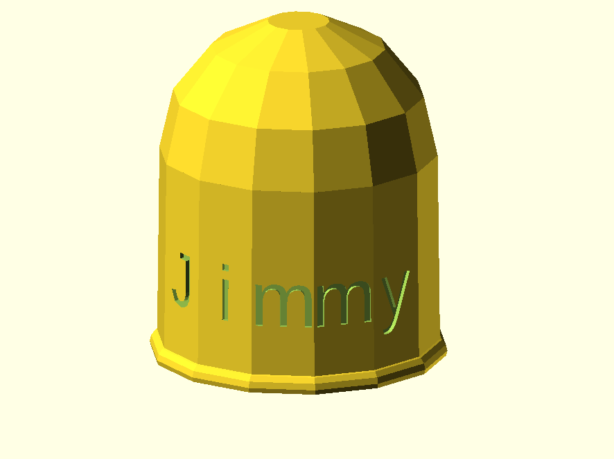
void addPixelColor(byte pixel, byte color, byte brightness) {
color *= 8;
uint32_t acolor = brightness;
acolor <<= color;
uint32_t ocolor = strip.getPixelColor(pixel);
ocolor |= acolor;
strip.setPixelColor(pixel, ocolor);
}

void drawClock(byte h, byte m, byte s) {
strip.clear();

addPixelColor(m, 1, dimmer);

if(hmark > 0) {
for(byte i = 0; i<12; i++) {
addPixelColor((5*i), 2, hmark);
}
}

h %= 12;
h *= 5;
h += (m/12);
addPixelColor(h, 2, dimmer);
// 0x RR GG BB

if(fader) {
byte dim_s1 = dimmer;
byte dim_s2 = 0;
byte px_s2 = s+1;
if(px_s2 >= 60) px_s2 = 0;
unsigned long curMillis = millis()-lastMillis;
if(curMillis < 250) {
dim_s2 = 0;
dim_s1 = dimmer;
}else{
dim_s2 = map(curMillis, 250, 1000, 0, dimmer);
dim_s1 = dimmer – map(curMillis, 250, 1000, 0, dimmer);
}

// Add blue low intensity dots for 12(0),3, 6 and 9 O’çlock to verify where the clock is positioned..
addPixelColor(15, 128, 10);
addPixelColor(30, 128, 10);
addPixelColor(45, 128, 10);
addPixelColor(0, 128, 40);

addPixelColor(s, 0, dim_s1);
addPixelColor(px_s2, 0, dim_s2);
}else{
addPixelColor(s, 0, dimmer);
}

// add a background color
// setBrightness(Serial.parseInt());
// uint16_t j;
// for(j=0; j<60; j++) { // 1 cycles of colors on wheel
// strip.setPixelColor(j, Wheel(((j * 256 / strip.numPixels()) + j) & 255));
// }

strip.show();
}

byte rounds = 0;

void loop() {
calcTime();

if(rounds++ > 100) {
Serial.print(ohour);
Serial.print(“:”);
Serial.print(ominute);
Serial.print(“:”);
Serial.print(osecond);
Serial.println(“(C)JG-2020”);
rounds = 0;

}
//rainbow(21);
if (osecond == 59){theaterChase(strip.Color(0, 0, 127), 40); }// Blue; }
//if (ominute == 59 AND osecond == 59){theaterChase(strip.Color(0, 127, 0), 50); }// Green}
//if (ohour == 11 AND ominute == 59 AND osecond == 59){theaterChase(strip.Color(127, 127, 0), 50); }// Green}
else {drawClock(ohour,ominute,osecond);}

delay(10);

chkSer();
}

void timeSync(void) {
RtcDateTime dt = Rtc.GetDateTime();
setTime(dt.Hour(),dt.Minute(),dt.Second(),dt.Day(),dt.Month(),dt.Year());

Serial.print(“Synced to: “);
Serial.print(dt.Year());
Serial.print(“-“);
Serial.print(dt.Month());
Serial.print(“-“);
Serial.print(dt.Day());
Serial.print(“-“);
Serial.print(dt.Hour());
Serial.print(“-“);
Serial.print(dt.Minute());
Serial.print(“-“);
Serial.println(dt.Second());
}

void timeSave(void) {
utc = now();

RtcDateTime store = RtcDateTime(year(utc), month(utc), day(utc), hour(utc), minute(utc), second(utc));
Rtc.SetDateTime(store);

Serial.print(“Synced to: “);
Serial.print(year(utc));
Serial.print(“-“);
Serial.print(month(utc));
Serial.print(“-“);
Serial.print(day(utc));
Serial.print(“-“);
Serial.print(hour(utc));
Serial.print(“-“);
Serial.print(minute(utc));
Serial.print(“-“);
Serial.println(second(utc));

}

void setBrightness(byte brightness) {
dimmer = brightness;
}

void chkSer(void) {
unsigned int iy;
byte im,id,iH,iM,iS;

if(!Serial.available()) return;

switch(Serial.read()) {
case ‘b’:
setBrightness(Serial.parseInt());
Serial.print(F(“Brightness changed to: “));
Serial.println(dimmer);
EEPROM.put(0, 0xAA);
EEPROM.put(1, dimmer);
break;
case ‘t’:
iy = Serial.parseInt();
im = Serial.parseInt();
id = Serial.parseInt();
iH = Serial.parseInt();
iM = Serial.parseInt();
iS = Serial.parseInt();
setTime(iH,iM,iS,id,im,iy);
Serial.println(F(“System time changed”));
break;
case ‘f’:
fader = false;
EEPROM.put(0, 0xAA);
EEPROM.put(3, 0);
Serial.println(F(“Fader off”));
break;
case ‘F’:
fader = true;
EEPROM.put(0, 0xAA);
EEPROM.put(3, 1);
Serial.println(F(“Fader on”));
break;
case ‘m’:
hmark = Serial.parseInt();
EEPROM.put(0, 0xAA);
EEPROM.put(2, hmark);
Serial.println(F(“HMark changed”));
break;
case ‘s’:
timeSync();
Serial.println(F(“Synced RTC to System”));
break;
case ‘S’:
timeSave();
Serial.println(F(“Synced System to RTC”));
break;
default:
Serial.println(‘?’);
}
}

// Fill the dots one after the other with a color
void colorWipe(uint32_t c, uint8_t wait) {
for(uint16_t i=0; i<strip.numPixels(); i++) {
strip.setPixelColor(i, c);
strip.show();
delay(wait);
}
}

void rainbow(uint8_t wait) {
uint16_t i, j;

for(j=0; j<256; j++) {
for(i=0; i<strip.numPixels(); i++) {
strip.setPixelColor(i, Wheel((i+j) & 25));//255
}
strip.show();
delay(wait);
}
}

// Slightly different, this makes the rainbow equally distributed throughout
void rainbowCycle(uint8_t wait) {
uint16_t i, j;

for(j=0; j<256*5; j++) { // 5 cycles of all colors on wheel
for(i=0; i< strip.numPixels(); i++) {
strip.setPixelColor(i, Wheel(((i * 256 / strip.numPixels()) + j) & 255));
}
strip.show();
delay(wait);
}
}

//Theatre-style crawling lights.
void theaterChase(uint32_t c, uint8_t wait) {
for (int j=0; j<4; j++) { //do 4 cycles of chasing
for (int q=0; q < 3; q++) {
for (uint16_t i=0; i < strip.numPixels(); i=i+3) {
strip.setPixelColor(i+q, c); //turn every third pixel on
}
strip.show();

delay(wait);

for (uint16_t i=0; i < strip.numPixels(); i=i+3) {
strip.setPixelColor(i+q, 0); //turn every third pixel off
}
}
}
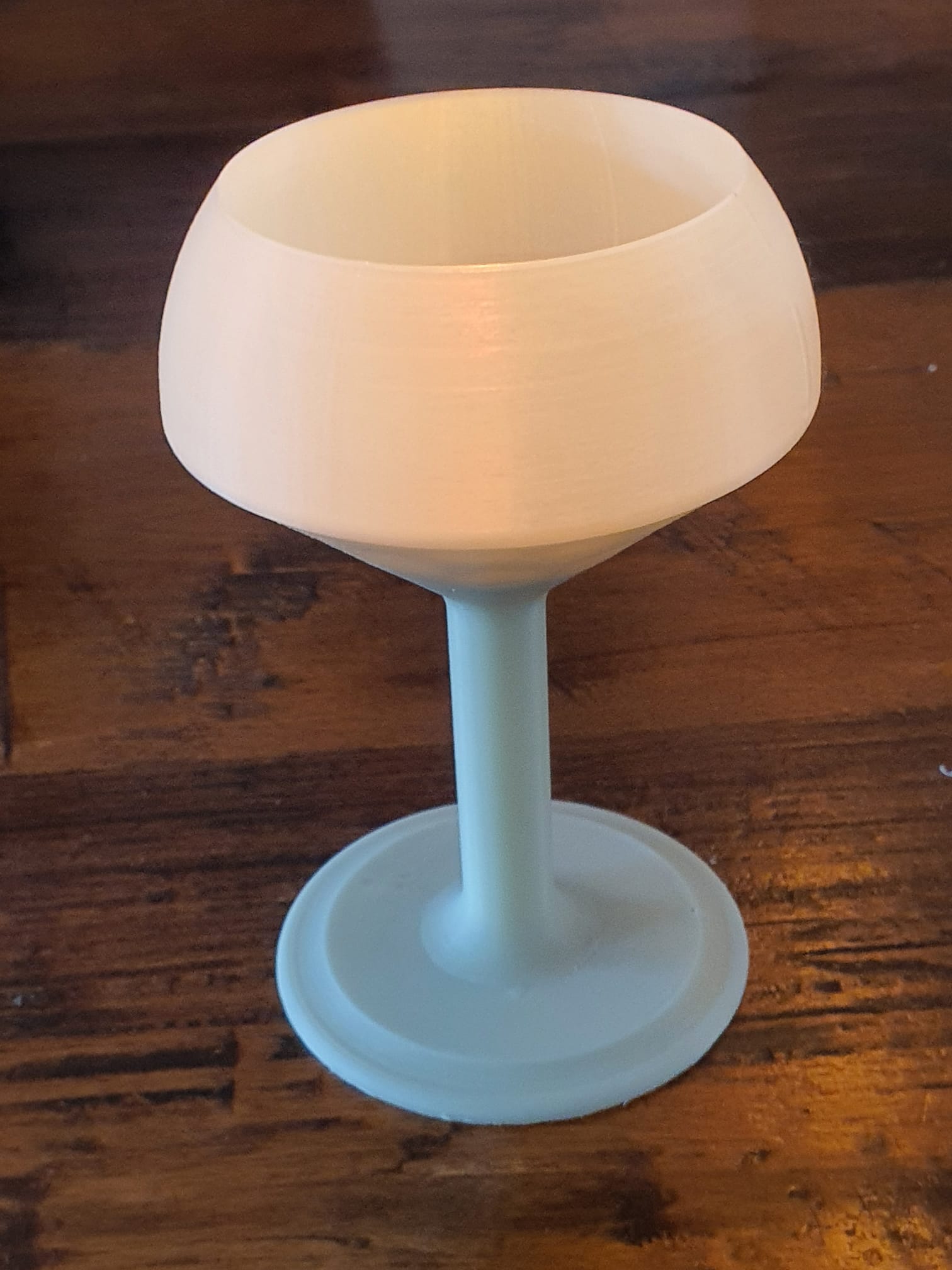
}
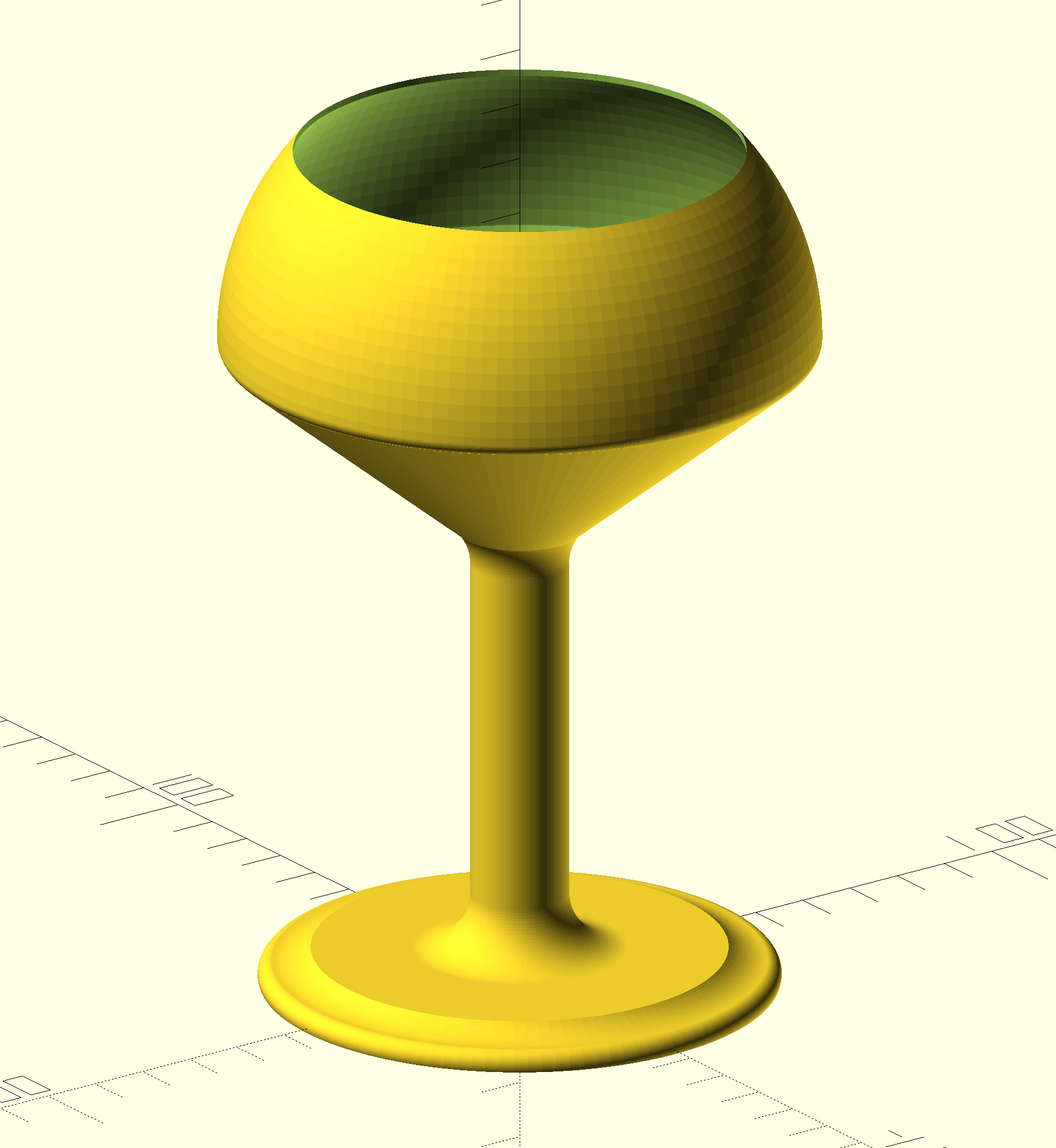
//Theatre-style crawling lights with rainbow effect
void theaterChaseRainbow(uint8_t wait) {
for (int j=0; j < 256; j++) { // cycle all 256 colors in the wheel
for (int q=0; q < 3; q++) {
for (uint16_t i=0; i < strip.numPixels(); i=i+3) {
strip.setPixelColor(i+q, Wheel( (i+j) % 255)); //turn every third pixel on
}
strip.show();

delay(wait);

for (uint16_t i=0; i < strip.numPixels(); i=i+3) {
strip.setPixelColor(i+q, 0); //turn every third pixel off
}
}
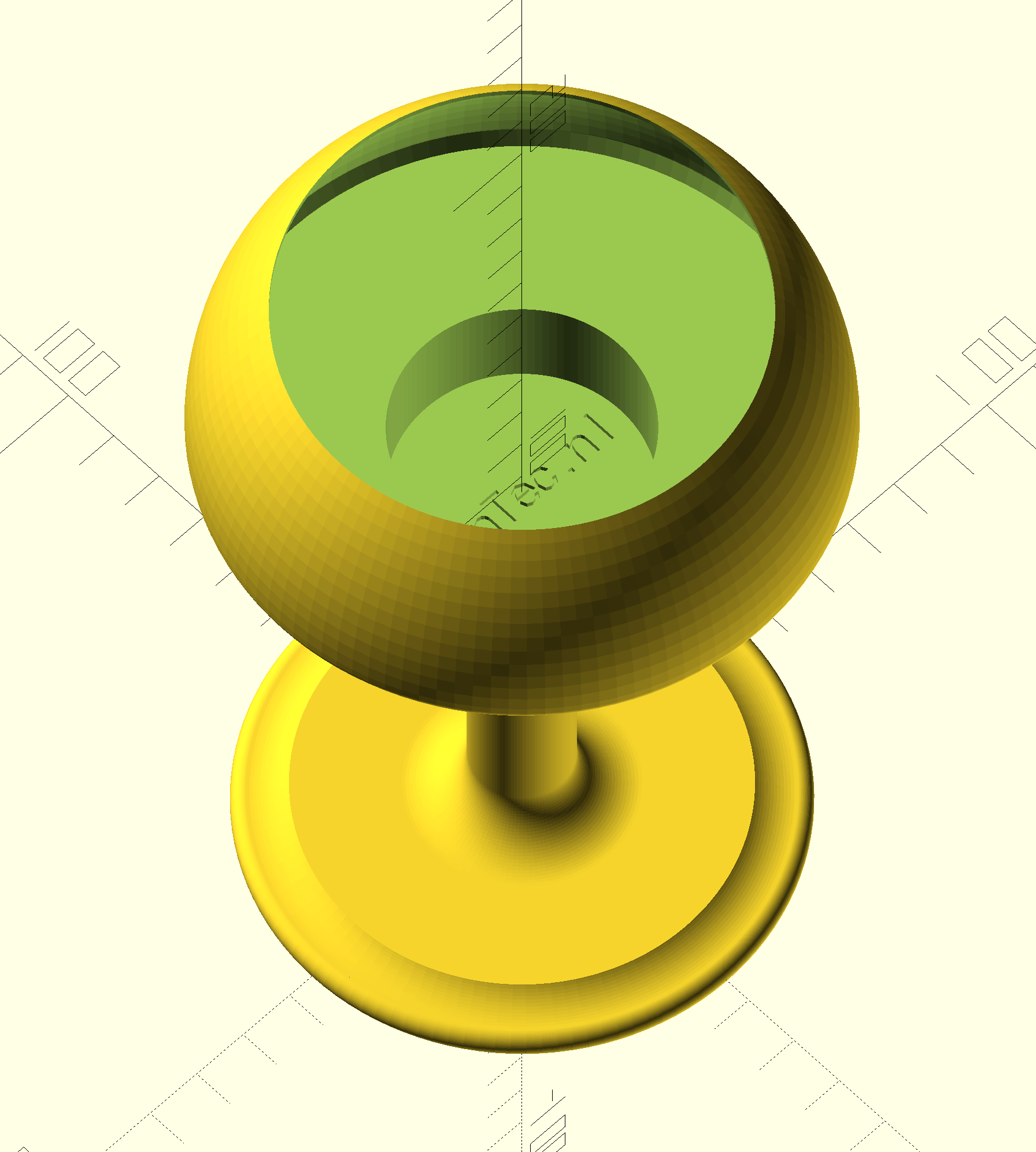
}
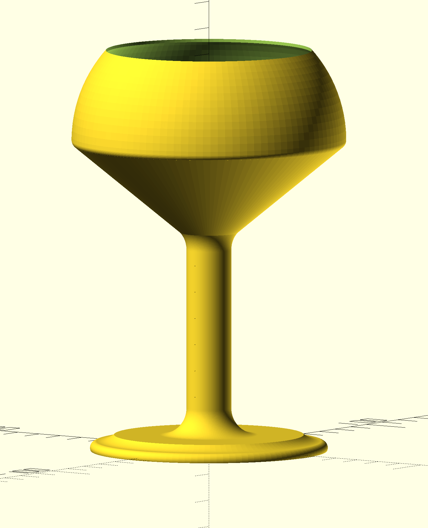
}

// Input a value 0 to 255 to get a color value.
// The colours are a transition r – g – b – back to r.
uint32_t Wheel(byte WheelPos) {
WheelPos = 255 – WheelPos;
if(WheelPos < 85) {
return strip.Color(255 – WheelPos * 3, 0, WheelPos * 3);
}
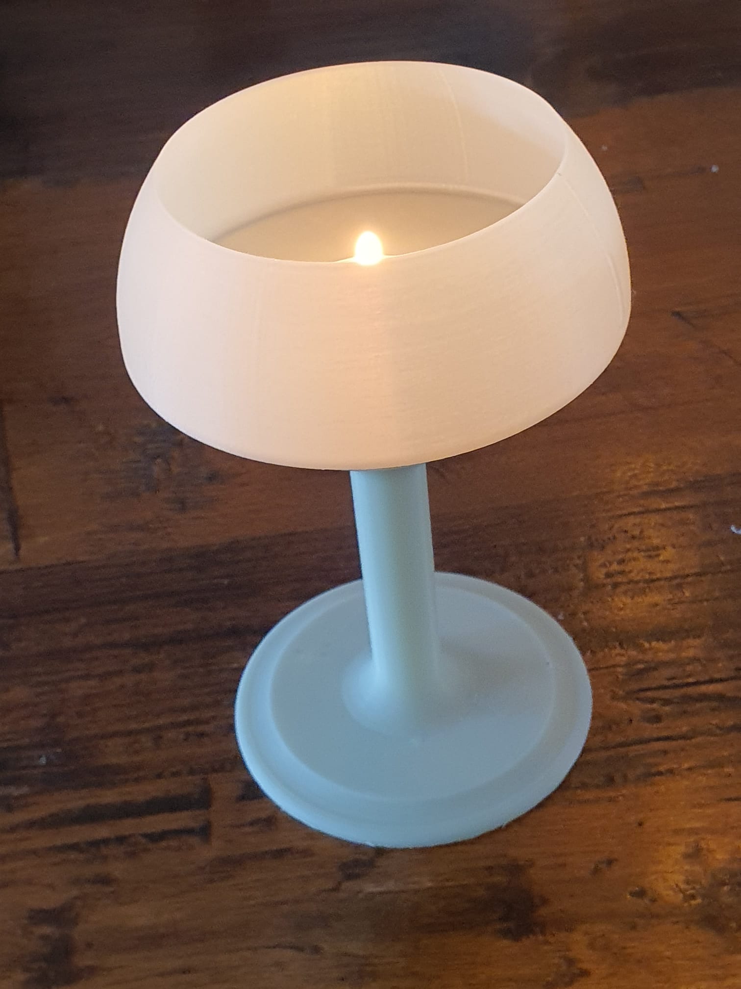
if(WheelPos < 170) {
WheelPos -= 85;
return strip.Color(0, WheelPos * 3, 255 – WheelPos * 3);
}
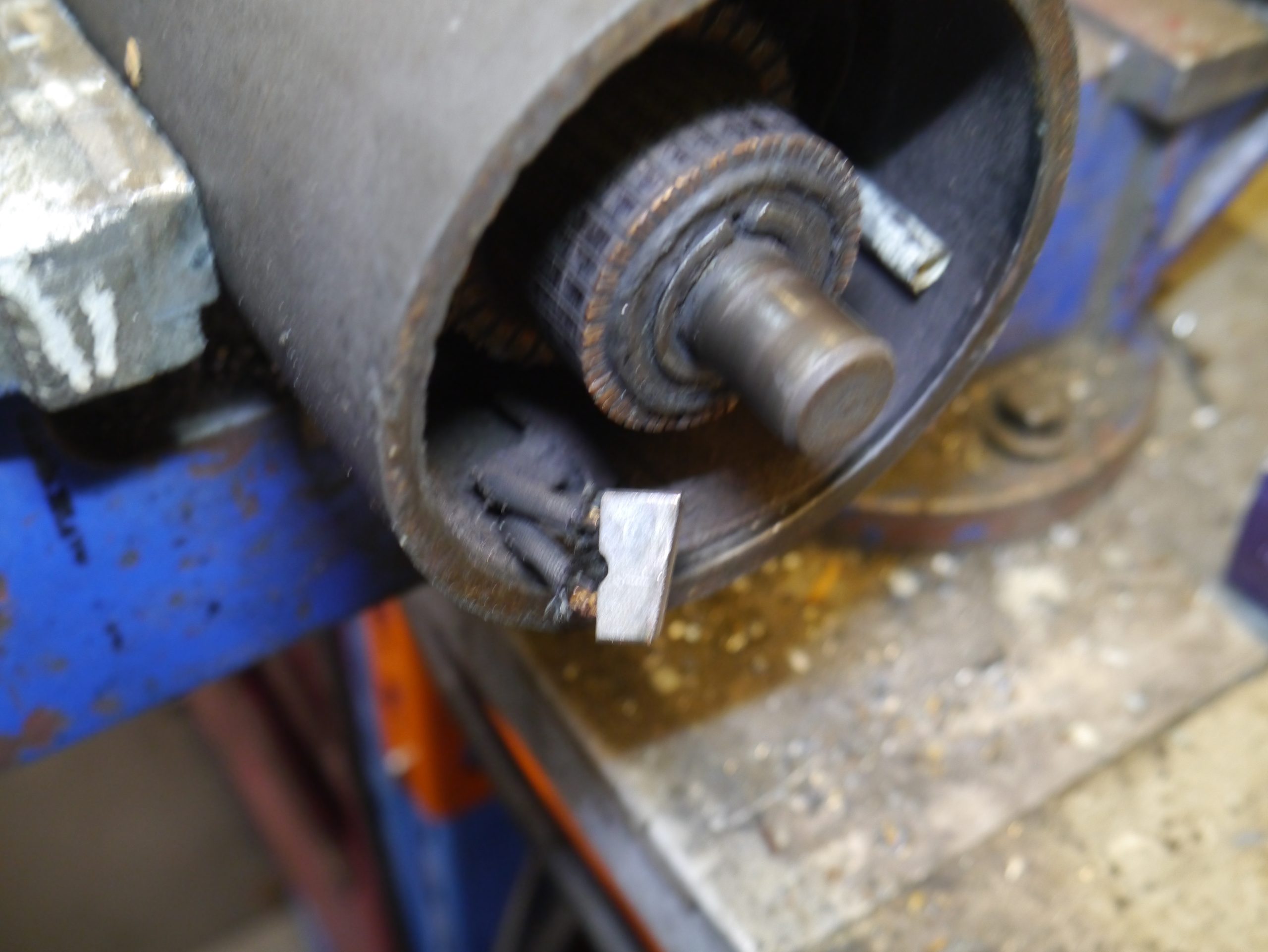
WheelPos -= 170;
return strip.Color(WheelPos * 3, 255 – WheelPos * 3, 0);
}
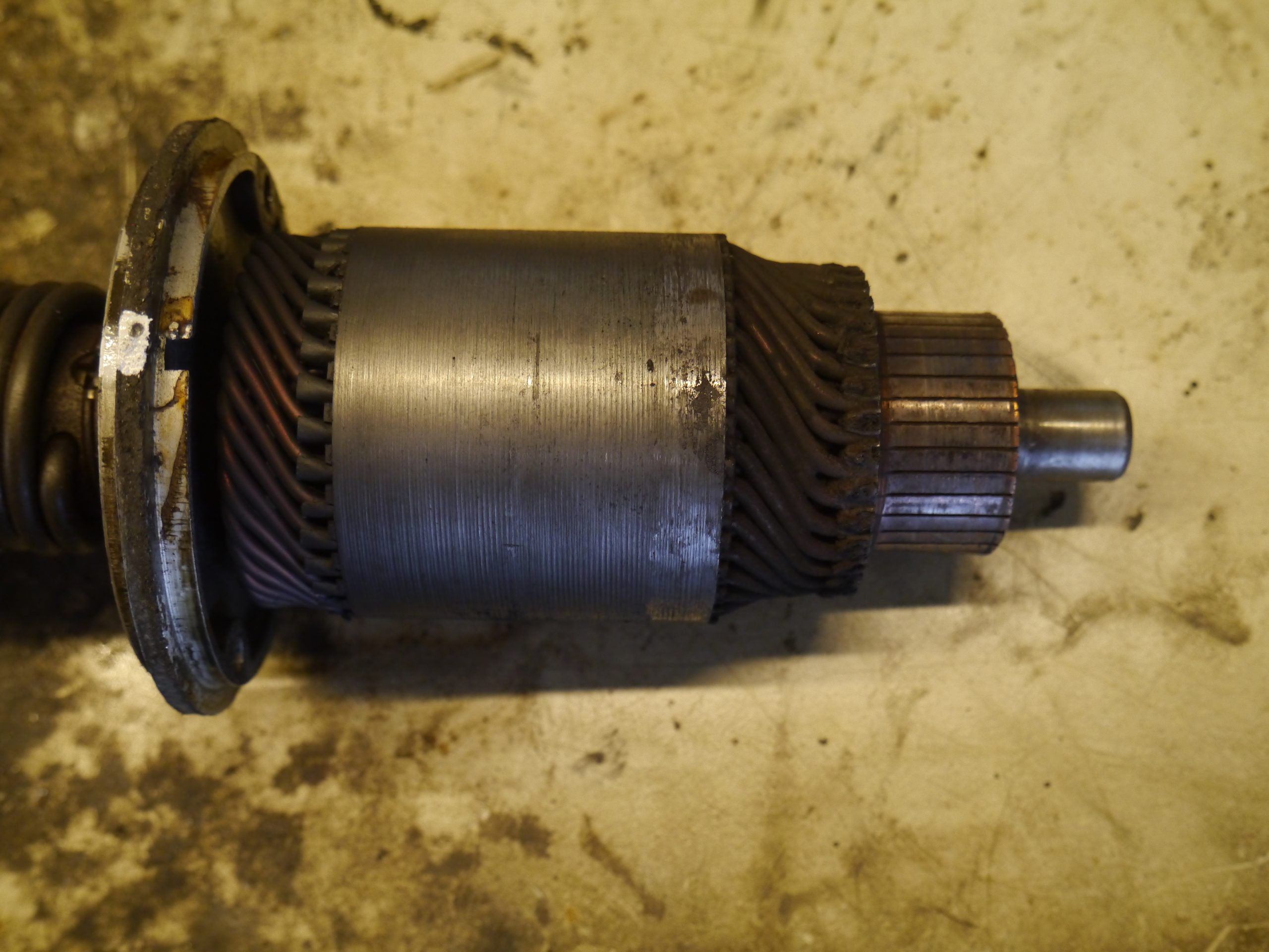
Posted on 6 June 20226 June 2022

Charging your EV over and above the public sidewalk with an extendable hinged cable jack

In the Netherlands, City councils usually forbid to put charging cables for electric vehicles on public pavements.

And- to charge your electric car, of course you want to use your solar panels and connect your EV directly to your own domestic power grid.

But what do you do when your municipality forbids you to lay the charging cable across the sidewalk to your car?

My municipality has passed a council resolution whereby you can order a charging station through an external party, and so then you can have a public charging station installed nearby.  Provided there isn’t already a charging point within a reasonable distance.  In my neighborhood there are hardly any charging points, and the only one I have been able to find niche about 400 meters away, consisting of 2 AC charging points where two cars are always charging.

In my search for possible solutions to still make it possible to get to the car via the public sidewalk so that I do get to charge the car at home, I have come across several solutions.  Of those solutions, only one is really useful, because all solutions with cable trays or cable protection over the sidewalk can still lead to liability issues if someone trips over the cable or is otherwise inconvenienced by the cable over the sidewalk.

The solution of using a hinged cable tree placed high on your facade to get the cable across the public sidewalk directly to your car is a pretty eye-catching solution.  But- the sidewalk remains free of obstacles and no one is bothered by it.  Except perhaps for the fact that it doesn’t look very pretty.  I wonder how the municipality would want to and can- prevent this solution.  After all, similar things like flags on the public sidewalk at a sufficient height are not enforced either. If that is even possible by law.

In terms of principle, it looks like this:

The lever can be moved upwards after use.  Then the whole tree falls away into the vertical holder.  Very nice, just a pity that the link to the supplier doesn’t seem to work anymore.

https://jantecnl.synology.me/wp-content/uploads/2022/06/YCB2131-charge_arm_promo0106.mp4

For my home situation, I prefer to place the lever on the facade. With a hinge point, the lever can then be moved away nicely against the facade after use, where you can attach the lever.

Below is an example of a company that makes these levers for hanging welding shields in factory halls.  They also exist in extendable versions up to a length of 6 meters.

When you create such a solution, it must of course comply with all the rules and regulations, and the design must be such that it fits in with the surroundings.  The choice of color and material is also a matter of concern, and it must not cause any inconvenience, such as clattering against the facade, etc.  And the structure must be professionally grounded.

I do expect resistance from the local authority because they assume that electric vehicles are still in the minority and that there is therefore no need for a serious solution for home charging in public parking spaces.

The world is changing so fast towards electric personal transport, the sale of new cars already consists for 10% of electric cars.  Of course the subsidy schemes help with this too, but all those cars sold are just going to drive and need charging spots.

Given the fact that people that already installed solar panels at their home are also the first people to drive electric cars, these people also want to use their installed solar panels for their electric transport.   And as long as the net metering regulation for the return of energy is still in force in the Netherlands, the pressure on necessarily wanting to charge the electric car at home will not be very great.  But with the rising energy prices suddenly making public charging much more expensive than charging at home, the pressure on wanting to charge at home using one’s own solar panels could become much greater.

VEHICLE TO LOAD

In addition, the latest development to run your home on your car battery is suddenly serious, because all brands now supply electric cars with a vehicle to load connection, which means that you can also use your charging cable to feed energy back into your home.  This means that during the day you can charge your car from your solar panels and in the evening you can use the energy from your car battery.  An average family consumes 8kWh in the evening and the car usually has about 50-70 kWh available.  Most private solar panel installations start at 8 panels and that is exactly enough to fully recharge the car for the use of 8kWh per day on an average day during the 8 so-called sunny months of the year.  And the months of November through February? You will still have to ‘buy’ electric energy during these 4 months.  Preferably with wind energy from a green supplier, of course.  When you drive your electric car to and from work every day,  recharging your EV from your solar panels for those days is obviously not true.  But when you regularly work at home, the story does apply for those days, as well as the periods during the weekends when you are plugged in at home.


Posted on 25 May 202225 March 2023

Indymill CNC Controller -tests and the final choice- and WHY

To get the best possible CNC driver / firmware setup, in combination with the CAD and CAM programs that are required, I tested the following setups with the Indymill hardware:

I have a setup running on the CMC Indymill with Duet wifi BUT I just can’t get enough current to my Nema23 stepper motors.

Therefore, I made the final choice to also test OPENCNC: https://blog.altholtmann.com/open-cnc-shield/

I am building this together as you can see in the below pictures, where the driver boards will be replaced with 6600 pro drivers.

In this post, some other possible choices are presented:

1) Reprap 3.3 & the Duet2wifi.  STL’s are made with OpenScad and then converted either online or with Estlcam to Gcode (.nc files).  The Gcode is then uploaded via Duet webinterface and run on the local reprap driver board.  Not chosen by me beacause it proved impossible to run a gcode stream online from the PC to the USB interface of the Duet2wifi board.  It is, however, possible to attach a serial handwheel to the Duet2wifi and manually control the CNC setup.  And dual axis squaring is also easily made possible.  Actually, the Duet reprap CNC setup is very mature and customizable.  I still have this setup as backup and by switching the connectors from the Indymill over, I can easily switch to this setup.  Some advantages of this setup are a.o.  the webinterface and the ease of having an automatic squaring gantry on the 2 Y axes with individual endstops.  I also learned that Estlcam can generate Gcode that I can then send via the webinterface to the Indymill CNC machine which works very well.  (I make my designs in Openscad and save this as .STL files. Estlcam can then convert these .stl files to .nc files…, using the machine configuration to get the code properly generated for the Indymill’s dimensions and hardware settings)

2) GRBL, Estlcam & Openscad, Marlin & GT2560 (A) board; This is also working out of the box and emulates a GRBL driver board. The main reason to NOT use this is the fact that the GT2560 board just has not got enough pins available onboard for things like a handwheel and other outputs for accessories.  The second thing that prevents me from going this way is the fact that it proved impossible to have a functional LCD attached that shows things like position, speed, status et cetera.
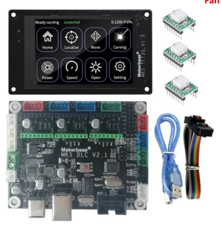
3) Mach3, FreeCad & USB CNC ‘barebone’ .  This is actually a very solid and reliable solution BUT I could not get it to do any way of squaring my dual Y axis setup.  Still investigating this…

4) GRBL, Estlcam & Openscad & MKS DLCV2.1 board with TFT 3.5 “;  Also for this setup: No option for squaring the dual Y axis setup.  But- this is a very neat solution for smaller machines.  or larger, if you use external drivers.  The nice option of this setup is the 3.5 inch LCD that also comes preconfigured for CNC.  I use this for my small 3018 CNC.
5) GRBL, Estlcam& Openscad & Mega2560 & RAMPS 1.6 shield. 

DUET2WIFI clone Mellow FLY-CDY-V2


MACH-3 with a generic USB-CNC converter

I also have an original USB Mach3 interface with a. o. a handwheel unit. This works very straight forward but needs a PC to keep a stream of Gcode commands running to the USB controller. I am not very fond of this solution since a little mishap will destroy your objects that is being carved.  But- this appears to work very well for many people so I have set this up after I had the FLY-CDY-V2 with the reprap 3.3 and the Duet webinterface running, to get to know the differences.  I must admit it works straight forward without any problem.  I decided to have this setup available next to the GRBL Mega2560/GRBL shield solution.  The thing that keeps me from the USB-CNC solution is primarily the fact that this setup cannot auto-square my dual Y axis gantry. The Mega 2560/GRBL shield solution does this squaring very well.


GRBL with MKS-DLCV2.1 and the TFT screen

And- the most in use hobbyist solution: The GRBL boards like the above shown setup from MKS.  I have this running on my old 3018 CNC milling machine and it always works well. This particular setup utilizes the preconfigured  KMS DLC 2.1 board and the preconfigured MKS TFT for CNC.  All is very neat and since the drivers can be adde externally as well as interanlly, it is possible to drive real high currents if you want that.  These boards don’t do sensorless homing and usually put the 2 Y steppers in serial.  This means that you will never be sure that they are well aligned.
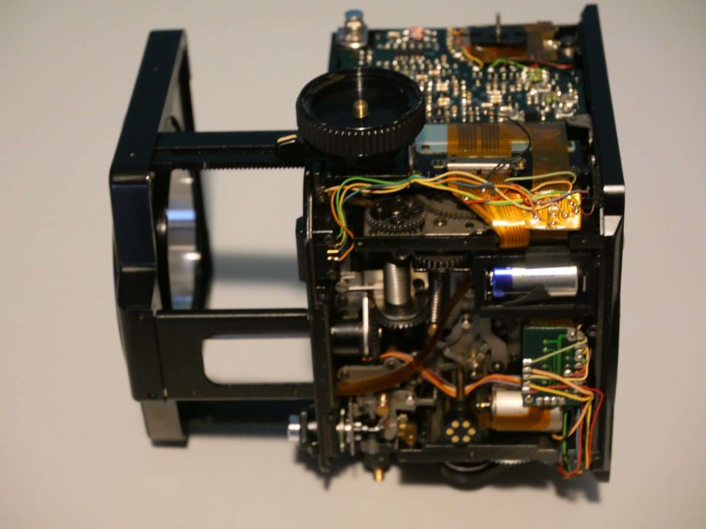
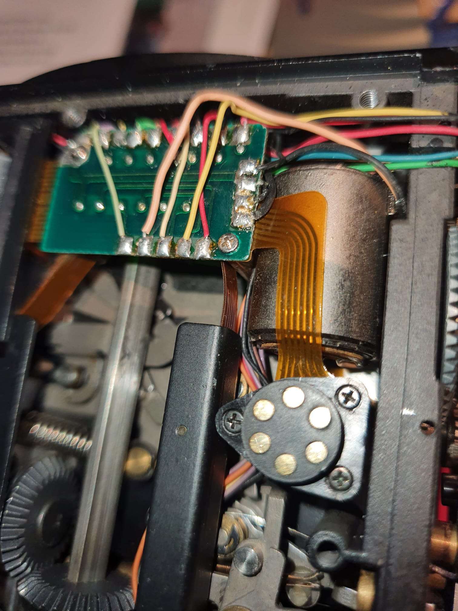
RAMPS shield for Arduino UNO and Mega2560 (and DUE?)

Still to discover:  ESP-based CNC board 6-axis on Openbuilds is very promising!

Unpopulated Controller

Posted on 23 April 202223 April 2023

STL files for Minimill WMD16LV CNC conversion direct drive CNC adapters downloads with NEMA23 steppers

Please donate $1 to my paypal account if you use (parts of) my developed materials so I can continue to share nice stuff for you to download

Click on the URL(s) to download the appropriate STL-file(s)

MINIMILL_BF16L CNC_Y_adapter direct 2022_07_25_V1_5-jantec.nl


MINIMILL_BF16L CNC_X_adapter direct drive 2022_07_25_V1_5-jantec.nl


STL download voor de TOP direct drive adapter van de WMD16LV minifrees en Nema23 stappenmotor

MINIMILL_BF16L CNC_Z_adapter direct drive 2022_07_25_V1_5-jantec.nl


Posted on 20 February 202225 February 2024

Mamiya Aptus leaf P65 V-mount user experiences 2022

My Mamiya RZ67 Professional received a digital back recently.

After a long search, I decided to get a V-mount digital back (originally for Hasselblad, old version cameras) version since an original Mamiya adapter plate to a Mamiya 645 mount is extremely expensive.

And an adapter for or a Hasselblad more poular H-mount is not very well supported, electrically.  I know that shutter release will work BUT the Phase One adapter plate that connects the Mamiya RZ67 Phase 1 Professional to the V-mount digital back is around 300 US Dollars and was available on eBay .

This is the adapter plate I bought between my RZ67Pro I and the V-mount digital back Aptus leaf P65

It took me some time to get everything working, since I did not have a P-P cable to connect the 2.5mm entry of the digital back to the shutter contact on the camera or lens.  This is required to get the digital back triggered at the moment that the shutter opens.

The setup looks like this:

The aptus65 works with standard samsung batteries of which I ordered a couple of the largest possible.

I also bought me a 64GB Compact Flash card, which works much better than the CF to SD adapter I used before.

Getting the pictures onto my PC works easy:  put the card in the CF reader , copy the files. Then the tricky part begins: You must transform the imported files with a decoding program that is fortunately downloadable on the mamiya leaf website, but it is a bit hard to find.

Then, import the required app for windows to edit the .MOS files in the regular image viewer, save a copy as jpg and you’re done.

It is also possible to use lightroom, or any other good imaging software package.

I also have a firewire cable setup that I used before for my digital8 camera’s.  This also works for the Aptus65, but I don’t expect to ever use this.

Firewire is btw the only way to power the Aptus65, if you don’t wanna use the batteries.  But you will need a very good power source on the USB-C connector to get this to work.

The images are very good, as to be expected.  the 28Mpix sensor is more tha adequate to get good results.  BUT it is a pity that the sensor is only 44×33 mm while the POV of theRZ67 is 7×6 cm.  This also means that you get only half the image (more or less) of what you see in the viewfinders’s image.

I printed a mask for the viewfinder at a crop of 1.3 vs. a 645’s normal view so the view resembles the taken pictures

That is exactly what is needed here, since the Aptus leaf65 has a crop of 1.3 when it would be used on a 645DF camera (which this V-mount version cannot, obviously do) with an (almost) 60x45mm medium format.

Which in fact is quite a bit less (53.7×40.2) in real image size, see the below table.

44×33 relates to 53.7×40.2 as a crop of 1.3, as the seller states in the folder of the Aptus 65.

Negatives:  Well, the rotating back does not work with the Phase One adapter plate, of course.  And I still have some cleaning to do on most of my lenses before I attempt to do any serious shooting outside.  And the entire setup gets quite heavy for outside use.

Positives:  It helps me a lot to work and learn with the RZ67, using the digital back.  I can shoot and shoot on, experimenting with light settings, flash, counterlights and so on without destroying any real film.

My intent is, though, to use the RZ67 with normal film and the full 7×6 capabilities.

And use it for architecture, mostly in Amsterdam.

I already have quite a lot of pictures, taken with my Sony A77RII &35 mm pro-lens and with my old Panasonic dual GX8 setup, but I am very much looking forward to get some great shots with the RX67 on large(r) format film in B&W!

Posted on 20 February 202225 April 2023

Mamiya RZ67 bellows replacement

Replacing the bellows of the RZ67 camera can be broken up in two parts:

1) The actual replacing as taking it out and in again, where the steel plates that hold the bellows are taken out and in with the actual bellows attached to this.  this procedure is described in the repair manual.n  You will need a very long X screwdriver for this, with a small nose.  And some patience, good lighting and (in my case) additional glasses.  And- if you replace the internal cloth part of the bellows: You will require some special light-blocking foam when mounting the bellows back in again.

2)The more complex replacement is taking the in-between cloth part of the bellows off the steel plating and replacing this with a new bellows unit, as you can buy on ebay/ aliexpress et cetera.  That’s what I will describe and show you in this post.

Steps to take:

Remove the cloth from upper-and lower part with use of dessicant, and tricloorethane or any other solvent that does not affect the paint on the steel plating.  ‘debonding might do the trick here.

Clean the steel plating.

Test-fit the new bellows on the steel plates;

put some glue on the rear steel plate, where the connection was in the old situation.

Put the bellows on the glued plate and use a brush with a bit of glue to attach the bellows to the steel plate.

Let it dry.

Do the same for the other steel plate.

Let it all dry.

Mount some foam as lightshield on the connecting part of the steel plates

First, mount the bellow to the camera’s largest part with the 4 screw in the corners( only 4 screws on this side!)

Then, extend the front to maximum and screw the bellows with the 9 screws to the front, through the camera’s inside.  Just screw the screws in a little bit, do not yet tighten. First do 3 or 4 on the outside, then the rest. After the last is in, tighten them all.

You’re done!

After the new bellows is  glued on the steel frame, part 1 will be done.

Now there is just a gap in the camera where the bellows used to be:

Posted on 20 February 202225 April 2023

Mamiya RZ67 repair shutter release electronics problem(s)

When repairing electronics, I always make a lot of picture up front. This helps especially with identifying the small components, both for the function as well for their specific value/type.

What makes this repair more difficult is the fact that, although I do have the repair manual, no schematics of the working of the electronics is available.

This means that I will have to work with the block schematics and the wiring scheme, only.

But- a reference is available for all of the voltages versus the pressed buttons at cetera. That will help, of course.  And I identified all SMD components, including the transistors.  Fortunately, all can still be bought online.

If you look at the added pictures, it appears that this REV2 print and its connected electronics have been upgraded- or repaired-  at an earlier stage.

That could mean that this identifies an earlier problem.

First, I checked all reference voltages related to the camera’s settings and then I identified anything out of the ordinary.

Posted on 20 February 202225 April 2023

Mamiya RZ67 cocking shutter repair

https://jantecnl.synology.me/wp-content/uploads/2022/02/WhatsApp-Video-2022-02-19-at-4.07.16-PM.mp4

As you can see in the above MP4, the shutter cocking mechanism could not fully complete the cycle to the end of the cocking prcedure, due to play in the connection between the small flange and the rod on which it is placed.

I ended up by just using strong thread sealer, screwing it tight again an waited for 24 hours before using it again.

Together with the beneath shown repair of the external lever play, this indeed fixed the problem of not reaching the end of the cocking procedure.

And thus my donor RZ67 camera housing was working again, albeit only in emergency mode.

But I will explain the repair of this specific electrical problem(s)  in yet another post.

And- also the same problem with the outside lever. The lever was easy to repair. I put it on my working table , on the flat part of my vice and used a blunt pointed driver and a dead blow hammer in the center of the small axle to punch it and this fixed the outside (big black) lever again firmly to the internal small lever.

Posted on 13 February 202214 July 2022

Scanning

[Update 2022-07-14: I got my Creality lizard today !

Extremely small and fast, I just tested it this afternoon and it is way faster and easier to use than the Creality CR-1!

More to follow soon, in a seperate post.]


Comparison of 3d-DIY hobby scanners versus Creality CR-1 3d scanner

Previously I built and extensively tested both versions of the Openscan scanners and the ciclop scanner.  The openscan types are very different from each other but use simple firmware with an Arduino or a Raspberry PI contoller.  The Ciclop is a simple 3d scanner with a rotating platform and a USB camera.

Openscan mini

The Openscan mini takes pictures with the RPI camera and rotates the camera around the object to be scanned.  This indicates the limitation, you can only scan small objects.  After scanning you have to import the photos into meshmaker or via the new free cloud solution from Openscan’s developer Thomas Megel.  The mini is fully controllable via the web-based software available for download on Thomas Megel’s website, where you can also use it to upload and process your photos and then download the 3d files.

Openscan mini + Raspberry PI (2-4)


Openscan classic

The classic version of the Openscan scanner can handle larger objects and uses an external camera. I used my Canon 5D Mark2 for this, with a ring flash.  This solution works pretty well and uses the same software as the mini for processing and rendering. In the separate Arduino unit that controls the rotors of the scanners you can set the number of steps vertically and horizontally and you have to transfer the pictures from the camera yourself to a meshmaker-like processing to construct a 3d image.  Quite cumbersome but it can be done for free and gives a pretty good workable result. Provided you spend some time on it.

Openscan classic 3d scanner with on the left the Arduino controller, with small buttons you can set the steps and on the LCD you can see what you are setting. Below is the connection for the remote to your camera. It is recommended to use a good flash or at least extra lighting.  The advantage of an external camera is that you can make razor sharp images, for example by using follow focus or, as I did on my Canon5DII, using continuous focus.


Ciclop 3d scanner

The ciclop scanner works with a fixed platform and no vertical movement. It is very similar in operation to the Creality CR-1 scanner but I have never had good results with it.  There are 2 red diode lasers on the sides and 1 USB camera in the middle.  The result in terms of photos is fine, but it is ultimately about the rendering software and the processing of the photos taken, just like with the Openscan classis. and that is for the hobby environment just in my experience not (yet) sufficiently well developed with this ciclop 3d scanner.


The Creality CR-1

I purchased the Creality CR-1 scanner in late 2021 because I saw a few projects coming up where a good scanner would come in handy, and I didn’t want to spend extra time on it.  Besides, I was very curious about the results of this ‘all-in one’ scanning solution.

The scans made are very useful, and the rotating plate on which you can place the object also works well.

My experience is that hand scanning is very laborious, and you have to scan all parts of the object to be scanned carefully.  This means that you have to pay attention both to what you are scanning through the screen, where you can follow the construction of your scan live, and what you are doing towards the object with the scanner in your hand.  That takes some getting used to, but after a few scans it is much easier.

Very nice is the way it works with this scanner: The live-view of the accumulated scan tells you where you need to scan even better and if you forgot something you scan again and let the included stitch software make one merged scan of it.  That also works very well.

What do you need besides the scanner: Saving the data is done on your PC or laptop, rendering is done via a GPU, and the control and power for rotating table and the scanner itself is done with a separate PSU.

It helps when you have a fast GPU with quite a bit of memory.  I have a 3600 GPU in a Thunderbolt3 external casing attached to my Dell XPS13 i7 for on-the-go use with 5 meter extension cords for the scanner.  This works very well, but really the 13 inch screen is too small for this work.  Carrying an external screen is not an option so I have to make do with this.  And the external Thunderbolt casing is actually too big to carry as well.

Another possibility would be to use a gaming laptop that already has a fast GPU in it, with a 17-inch screen.  Might get one anyway, when more work on the go comes along.  For now, I mainly use the scanners at home/business so I just use my hi-res 27 inch IIyama screen to the Thunderbolt / 3600 GPU, that works fine!

Experiences:  This scanner works completely differently than the Openscan versions.  The camera needs more distance from the object to be scanned and therefore the whole setup requires more space. I had to get very used to the fact that you have to have more than a meter all around to get a good view of your object, even with small objects.

I am still going to try using a front lens or zoom lens, need to check what fitting this scanner uses for the lens-to-sensor.


Summary and overall rating from 1-10:

The Openscan mini (7) works fine for small objects, is easy and good to use with the web-based software and with the online rendering service.

The openscan classic (6) works well but requires a relative amount of setup work, knowledge of and experience with the setup an you can use the same online rendering service from Thomas Megel.

The Ciclop (3) is in my opinion too immature to use seriously.

The Creality-CR1 (8) is a valuable professional solution for medium size projects up to large projects (10-200cm diameter), good local interface via PC/Laptop with fast processor and fast modern GPU.


Posted on 11 February 202223 April 2023

Mamiya RZ67 + Aptus leaf 65 + Phase One adapter Hasselblad V-mount

2022-02-10: FIRST ENCOUNTERS – RZ67 system & APTUS leaf 65

Recently I received some extra money to persue an old dream:

Get a medium format camera with a digital back and make some awesome architectural pictures!

I know that the Hasselblad/ Zenza Bronica/ Mamiya/ Phase One and some other’s medium format camera’s can produce awesome results, and that they are mainly used for non-moving os slow moving objects.

But- I am more of a digital type than analogue.

So-I really wanted a Hasselblad sort of camera with the awesome 39Mpix digital back.

But my budget is limited, so I had to get my wishes adapted to my budget.

In the end, I ended up with a set of Mamiya RZ67’s, both with a known problem so I could make 1 working camera out of 2 non-fully functional ones.

I exchanged the bellow from the 1 to the other camera, so this one is now in full working order. the donor camera has firing issues. I will repair the donor later. I downloaded the repair manual for the RZ67 camera and it is extremely well documented in English, including pictures and all.

The donor camera has a plastic shutter cocking handle whereas the receiving camera has a metal one. which btw has somewhat another shape. The donor’s handle (shown in the above picture) has quite some play on the handle and I expect this to be one of the main problems to be solved.

The repair went very well and within a period of 4 hours I had 1 completely working operational RZ67 camera and 1 donor camera with a lot of loose parts, that I will repair upon receival of the new bellow I ordered from AliExpress for 70 Euros.

The camera’s were acquired from Japan, like most of the other parts except the digital back that comes from Sacndinavia:

  • 4 Lenses (50mm, 110mm, 100-200mm and 250mm);
  • An original 1.4 x teleconverter;
  • Both original wired extension tubes for macro photography;
  • A Leaf Aptus 65 V-mount 28 Mpix digital back;
  • The required adapter plate from Phase One to convert RZ67’s back to V-mount;
  • Plus a lot of accessories like a left handgrip, an AE diaphragm viewer that enables automatic lighting (Aperture prio-only where the shutter speed is automated) , belt diaphragm viewer, film back 60x70mm and so on.

I got the lenses from ebay, and two of them really need some internal cleaning.

The one that works best is the 250mm lens.

I got some pictures taken right after everything got mounted on the rig, through the window at home.

I used the AE finder on Automatic, and set the lens’s aperture at 32 to get the sharpest details.

The automatically generated (and set) shutter speed when the position switch of the AE prism viewer is set at ‘A’ in broad daylight against the clouded sky turned out to be around 1/15 second which seems quite long.

And the picture of the tree  branches with some birds sitting on them turned out beautifully!

This tree is about 100 feet from my house (30 meters), and the couple of branches fill all of the screen, so the telephoto power of this combination is working very well.

This first digital photo that I made with my RZ67 digital kit and the 250mm Z- Mamiya lens is shown below:

Another thing to get investigated is that the 50mm lens does not get well into focus at all.

Like the front of the camera does not get close enough inside the camera.

The 250 mm works awesome and the 100-200 is fine as well, since this lens has its own focusing ring at the front of the barrell.

What I could not get to work -yet- is the ISO setting. If I set ISO on the Aptus to 400, the AE system of the RZ67 does not recognise this, since I get overlighted images.

I adapted this by setting the lighting correction to +3 on the AE viewfinder which made me produce OK pictures but this does not solve my original issue, since I want it to work automatically.

I really want to use this setting, instead of compensate for it so the Aptus gets less light.  Still working on this.

I will measure the adapter’s electrical output on the right pin for the signal to change, like the analogue filmbacks do when you change the ISO settings.

If needed, I can hook up a small switch to the adaptor for ISO settings.

But I am sure it has something to do with settings in the Aptus 65, since you can configure almost anything and I am still finding out what I need to set for this to work properly with the Phase One converter plate.

The complete setup looks like this, with the 100-200 mm zoomlens attached:

I will not be running around with this outside, since the combined weight is over 4 kilograms.  Just too much if you want to seriously shoot anything that is any good.

This will be my studio-, & macro-, and architecture camera since the shallow depth of field will produce amazing pictures, both in B&W and in color.

Maybe a commercial photograph session now and then, I believe that getting a technical factory  shot with this cam/combination could turn out to work very nice!

Compact Flash cards:  I used an adapter from CF card to SD card that I also use on my Canon 5D MarkII, and it only accepts SD cards up to 32 GB.  But that’s OK.  I will try to install the wifi SD card as well, since I have that lying arouns somewhere, I will add this in a new post later.  The Aptus’s firmware had a setting for this, so I will try this anyway.

The digital back adapter for the RZ67 camera  is not really visible between camera and digital back, underneath is a picture of the one I use.  It is commonly available but requires a V-mount digital back.  V-backs from Leaf or Phase one are very rare to get by, since they are either Mamiya fit (proprietary mount for for the 645 cams) or H-Hasselblad fit.  And Hasselblads V-mounts digital backs are very good and fairly easy to get at, yet they are (in my view) very expensive due to their high quality and high pixel rates.

CROP FACTOR

The Mamiya Leaf Aptus 65 has a 44×33 mm sensor of almost 29Mpix.  The Aptus has been made for the 6045 line-up and therefore all specs relate to that, and not to the RZ67’s 6×7 cm format.

The maximum (theoretical) film format on the RZ67 is 70x60mm.  But the picture size with a 6×7 cm back will be 56mm x 69.2mm.

Even though, most common used on the RZ camera are the 6070 film backs, although a 60×60 is also available but hard to get for a fair price.  The 6070 backs are the ones without anything in size labeled on top.  Any 6060 or 645 sized back will have this size labeled on the pack’s outside.

The Aptus 65’s crop of 1.3 is defined by Leaf in relation to the medium format definition and this is theoretically only 60x45mm but it is adjusted down, due to cutoffs and such.  60×45 camera size is measured in medium format picture size as 53.7×40.2mm.

The medium format is thus generally defined at 53.7×40.2 mm picture & sensor size, and its surface is 21.59cm2.

The Aptus 65’s  sensor is 33x44mm and its surface  is ‘only’  14.52 cm2.

The crop factor of the Leaf Aptus 65 is 1.3 versus medium format.

The full-frame sensor against which all other image sensors are defined is 36×23.9 mm and its surface is 8,6 cm2.

So- even the fact that you won’t use the full width of the 6×7 cm range of the RZ67’s back panel’s covered projection space, the coverage of the Aptus 65’s sensor almost doubles that of a full frame sensor.

The used table is below:

I am, however, still out on the search for a Hasselblad CFV-39 V-mount digital back since it has the extremely good Sony sensor of 49×36.7 mm and it has great specs and image results.  Still hesitating to buy this since the prices are above 3000 Euro’s, excluding import duties and VAT.  So- adding this makes it cost over 4500 Euro’s.  I am still searching for one within the EU, so I don’t need to pay additional costs before I get it.

Posted on 23 January 202223 January 2022

Lomography with my old 35mm Canon T70, T90’s, EOS500 and my Lubitel’s 6x6cm

Ever since my kids got an interest in lomography early 2021, it started itching in my head.

I have a lot of analogue photo equipment stowed away, just because I can never throw anything away that might possibly turn out to be useful someday.

So- I got a supplier for my juices and film and I tried reviving my cams.  That turned out to be more difficult than I expected.

The T70: no problem, just put 2x AA batteries in it and it’s OK.

But-my favourite T90’s just would’nt fire any shots.  After a lot of reading on the net, I finally found the problem: One of the coils appeared to require some magnetism from a nedymium magnet and all works well again!

So I did this and it worked. Actually, I removed the magnet and the camera kept working for some time.

https://jantecnl.synology.me/wp-content/uploads/2022/01/WhatsApp-Video-2022-01-23-at-10.13.47-PM.mp4

But next day I had to do the same ritual again. and again.

Here’s the largest Neodymium magnet I used, with the white dot on top. It only worked well in this exact position. Any other side up and it would not work well. Turning the magnet also made the magic repair disappear. I left it in a couple of hours and the shutter kept working. Shut it off for the night and it would no longer work next morning.  The magnet can’t stay in, obviously since it is blocking some other moving parts.


So- the T90’s are in the storage again.


And- My newer Eos 500 worked perfectly! Everything automatically, AF and all! This is just a modern camera that has all you may need.  The EF lenses all fit so I can start shooting with this 35mm cam, again!

I will only do B&W, since my enlarger and all of my dark room equipment is for B&W.  I received the needed liquids last week, and I’m ready to go!

I will add new posts and add the links above when I start developing my first roll of 35 mm film, in black and white !


Posts pagination

Previous page Page 1 Page 2 Page 3 Page 4 Next page

Privacy Policy Proudly powered by WordPress